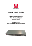
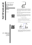
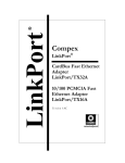
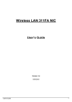
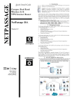
1
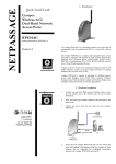
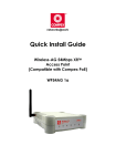
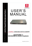
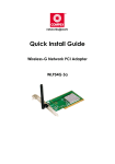
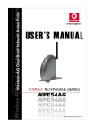
Quick Install Guide
Wireless-G Broadband Multimedia Router
Compex NetPassage 27G
TABLE OF CONTENTS
1: INTRODUCTION .......................................................................................... 1
Package Content .................................................................................... 1
2: NETWORK INFRASTRUCTURE ...................................................................... 2
3: LET’S GET GOING-HARDWARE SETUP ........................................................ 3
Power Up in 4 Steps .................................................................................. 3
4: GETTING STARTED WITH WIZARD SETUP ..................................................... 4
5: CONFIGURING TCP/IP SETTINGS............................................................. 12
6: CONFIGURING WIRELESS NETWORK CONNECTION............................... 14
7: SCHEMATIC OVERVIEW ........................................................................... 15
8: TECHNICAL SPECIFICATION .................................................................... 18
i
Chapter 1
Introduction
1: Introduction
Thank you for purchasing the Wireless-G
Broadband Multimedia Router. This WirelessG router with two USB1.1 ports connects the
USB devices to be shared with others. Typical
devices include printers and hard drives.
There are endless possibilities with what you
can do using this Multimedia router.
Download songs and store them in the
shared hard drive so others can play them as
well. Download photos save them in the
shared USB hard disk and print them to the
shared USB printer.
Of course, it is also a full-fledge router allowing you to share the broadband
Internet connection with several users in your home. The router is, additionally,
equipped with advanced features that will make it suitable for the office as
well.
Package Content
The router retail package contains the following items to start you off:
•
•
•
•
1x Wireless-G Router
1x External Power Adapter
1x Quick Install Guide
1x Product CD (containing User’s Manual, Firmware Recovery Tool &
Utilities)
1
Chapter 2
Network Infrastructure
2: Network Infrastructure
Only a few simple steps are required to set up the router to begin sharing your
broadband Internet connection between your wired and wireless network
clients.
Example: Broadband Internet Access Distribution to a Fast Ethernet Network &
Wireless Network
Wireless LAN clients access
the Internet and the wired
LAN via the router
Connect from
Cable/ADSL Modem to
WAN port
Router
Connect from computers to
the integrated 4-port
10/100Mbps switch to form
wired LAN
2
Chapter 3
Let’s Get Going – Hardware Setup
3: Let’s Get Going-Hardware Setup
Power Up in 4 Steps
In 4 simple steps, you shall have your router wired and functional. After which,
you may proceed to the software configuration to get ready to surf the Internet
at high-speed!
Connect one end of the Ethernet cable to your Cable/ADSL modem,
and then connect the other cable end to the socket labeled WAN on
the router.
Connect one of the LAN ports to a PC with an RJ45 Ethernet cable.
Connect the USB devices (such as storage disk or printer) to the USB
ports of the router.
Next, plug in the power adapter that is supplied to the main electrical
supply, and connect the power plug to the socket on the router.
Please do not turn on the power during the installation for safety
reasons. Reboot the PC.
3
Chapter 3
Let’s Get Going – Hardware Setup
4: Getting Started with Wizard Setup
1.
Insert the Product CD to your CD-ROM drive, go to the Utilities section and
run the uConfig program.
2.
The program will prompt you with the following message. Click on the Yes
button to proceed.
3.
Select Wireless-G Broadband
Multimedia ROUTER and click
on OpenWeb button.
Alternatively, you may also
launch your Internet Explorer
browser (or Netscape). At the
Address
field,
key
in
http://192.168.168.1.
Next, the system will prompt
you not to close the uConfig
program until you wish to exit
your
web-based
interface.
Click Ok button to proceed.
4
Chapter 3
Let’s Get Going – Hardware Setup
4.
Next, an authentication page
will appear as shown on the
right. The default password,
which is password, is preentered in the field provided.
Click on the LOGIN! button to
access the main page of the
router.
5.
Check the radio button next to Basic Setup. Click on the Next button.
5
Chapter 3
6.
Let’s Get Going – Hardware Setup
The first page of the Setup Wizard will appear, showing an overview of the
basic setup.
• Internet Connection
This functionality lets you
specify the type of Internet
Connection you are using.
• Wireless Setup
This functionality lets you
configure the settings of the
router to suit your wireless
network.
• Router Settings
This functionality lets you
identify the router and create
a workgroup for the router. It
also lets you set up your local
time zone.
6
Chapter 3
7.
Let’s Get Going – Hardware Setup
Select your WAN connection,
from the following types of
Internet Connection:
• Static IP
For configuring Static IP, you
need to manually enter the IP
Address, Network Mask and
Gateway IP Address that are
provided by your ISP.
• Dynamic IP
(used as an example in this
guide)
• PPPoE
For configuring PPPoE, you
have to enter the account
Username and Password that
are provided by your ISP.
• PPTP
For configuring PPTP, you have
to
enter
the
account
Username, Password, Network
Mask and VPN Server that are
provided by your ISP. Take
note that VPN Server refers to
the IP address of your ISP’s
PPTP server.
• L2TP
For configuring L2TP, you have
to click on the Change button
and
enter
the
account
Username, Password, Network
Mask and VPN Server that are
provided by your ISP. Take
note that VPN Server refers to
the IP address of your ISP’s
L2TP server.
To proceed, click on the Next
button.
7
Chapter 3
8.
Let’s Get Going – Hardware Setup
To set up your wireless network,
configure
the
following
parameters:
• SSID
The default SSID is ‘router’.
Click on the Change button to
enter your preferred SSID
name.
• Channel
Click on the down-arrow
button next to Channel. From
the list, select your preferred
wireless network channel.
• Security Mode
You may choose to enable
WEP or WPA-PSK to secure
your
wireless
network
connection.
If WEP is enabled, select Hex or
ASCII for the key string type to
be used. Select 64Bit or 128Bit
for the transmission key. Then
enter
the
corresponding
transmission key.
Use the Reset button to clear
the transmission key.
8
Chapter 3
Let’s Get Going – Hardware Setup
If WPA-PSK is enabled, select
Hex or ASCII for the key string
type to be used. Change the
default WPA-PSK key that is set
to ‘11111111’. The default GTK
update is ‘600’(recommended
value)
To proceed, click on the Next
button.
Please ensure that your router and
wireless client settings match.
9.
To check your system’s identity
and time zone:
• System Name
The default name is ‘ROUTER’.
You may change it to a better
name that will better identify
your router.
• NetBIOS Name
This is the name under which
the router will appear when
you browse the MS Windows
Network Neighbourhood. You
can change it to another
name that will help you to
better identify your router.
9
Chapter 3
•
Let’s Get Going – Hardware Setup
Workgroup
The
default
name
is
‘mygroup’.
Create
an
appropriate name for the
workgroup to include your
router and network clients.
• Time Zone
Choose your local time zone
from the drop-down list.
To proceed, click on the Next button.
10. You will see a summary of the router setup appear. Check if the settings
such as WAN IP Address, etc are correct.
10
Chapter 3
Let’s Get Going – Hardware Setup
11. Click on the Back button to go back to the previous page or click on the
Finish button to save the settings and reboot the router.
12. You will be returned to the Login page after 30 seconds.
!
Note: The factory default password to access the webbased interface is <password>. It is recommended that
you change to another stronger password by following
the steps described in section System Tools : Change
Password.
11
Chapter 5
Configuring TCP/IP Settings
5: Configuring TCP/IP Settings
You should configure your PC or wireless client to obtain IP address
automatically. For users of Microsoft Windows XP, you may configure the TCP/IP
settings as follows:
1.
Click the Start button. Select
Settings and click the Control
Panel icon. Then double-click
the
Network
Connection
icon.
Right click on Local Area
Connection
or
Wireless
Network
Connection
corresponding
to
the
Ethernet adapter you wish to
connect to the router.
2.
Under General tab at This
connection uses the following
item, make sure the box next
to Internet Protocol (TCP/IP) is
checked.
Then
highlight
Internet Protocol (TCP/IP),
and click the Properties
button.
12
Chapter 5
3.
Configuring TCP/IP Settings
Check the radio button next
to Obtain an IP address
automatically.
Then click the OK button on
this page, and the OK button
on the previous page it
returns you to.
13
Chapter 6
Configuring Wireless Network Connection
6: Configuring Wireless Network Connection
In the following chapters, you will find information on how to configure the
router to function in your network, to access the Internet and to begin sharing
the connection with your wired and wireless clients.
1. Right-click
on
Wireless
Network
Connection corresponding to the
wireless Ethernet adapter you wish to
connect with the router, and click on
Properties.
2. At the Wireless Networks tab, click on
the Add button under Preferred
Networks.
3.
At the Network name (SSID) field, type
in ‘router’ (the router’s factory default).
Click OK.
14
Chapter 7
Schematic Overview
7: Schematic Overview
Front View of Router
2
3
1
Name
LAN Link/Act LED
1, 2 3, 4
4
7
5
Steady GREEN
6
Description
LAN connection is on.
Flashing GREEN
Data transmission at LAN
connection.
WAN LED
Steady GREEN
WAN connection is on.
Wireless LAN
Link/Act LED
Steady GREEN
At least one wireless client is
present.
Flashing GREEN
Activity is detected in the
wireless network.
WAN Link/Act
LED
Flashing GREEN
Data transmission at WAN
connection.
USB LEDs 1, 2
Steady GREEN
USB device is detected.
Flashing GREEN
Data transmission at respective
USB ports.
Power LED
Steady BLUE
The device is powered up.
Diagnostic LED
Flashing GREEN
This indicates that the firmware
has become corrupted.
15
Chapter 7
Schematic Overview
Back View of Router
8
9
10
11
12
Name
External
Antenna
Description
Foldable, non-detachable antenna
5 VDC
Power Input
WAN (RJ45 Port)
WAN port connects to Cable/ADSL modem
USB Ports 1, 2
Integrated USB1.1 Ports
LAN RJ45 Ports
1, 2, 3, 4
Integrated LAN Switch Ports
16
Chapter 7
Schematic Overview
Bottom View of Router
13
Name
Reset Push button
Description
To reboot, press once.
To reset password, press and hold the button for
5 seconds. The DIAG light will flash fast for
about 5 flashes/sec before releasing the
button.
To restore the factory default settings, press and
hold the button for more than 10 seconds. The
DIAG light will flash slowly for about 10
flashes/sec before releasing the button.
17
8: Technical Specification
Industrial Standards
Wired:
•
•
•
IEEE 802.3 10Base-T
IEEE 802.3u 100Base-Tx
IEEE 802.3x Flow Control
Wireless:
•
•
IEEE 802.11b
IEEE 802.11g
WAN Interface
1x Auto MDI/MDI-X RJ45 Ethernet Port for external
Cable/ADSL modem
WAN Type
•
•
•
•
•
Static IP
Dynamic IP
PPP over Ethernet (PPPoE)
Point to Point Tunneling Protocol (PPTP)
Layer 3 Tunneling Protocol (L2TP)
Wired:
•
Integrated 4x Auto MDI/MDI-X RJ45 Ethernet
Port for 10/100Mbps Switch
Wireless:
•
Operating frequency channels of:
- 11 Channels 2.400~2.4835, US, Canada
- 13 Channels, 2.400~2.4970, Europe
- 4 Channels 2.400~2.4835, France
•
Direct
Sequence
Spread
Spectrum
modulation, Orthogonal Frequency Division
Multiplexing modulation
•
Data rates: 54Mbps, 48Mbps, 36Mbps,
24Mbps, 18Mbps, 12Mbps, 11Mbps, 9Mbps,
6Mbps, 5.5Mbps, 2Mbps, 1Mbps
•
Security:
- 64-bit/128-bit WEP
- WPA, WPA-PSK
- Wireless Pseudo VLAN
LAN/WLAN Interface
18
USB1.1 Ports
2X integrated USB ports supporting:
• Print Server
• Storage disk drive
IP Addressing
All Classful/Classless subnets
Built-in DHCP Server
Yes
DHCP Reservation
Yes
NAT Firewall
Yes
Stateful Packet Inspection
(SPI) Firewall
Yes
Load-Balancing/Fail-Over
Redundancy
Parallel Broadband
Virtual Server
IP and Port Forwarding, De-Militarized Zone
hosting
IP Packet Filtering
Time-based, TCP Port, Source IP Filtering
Multicast Filtering
Yes
URL Filtering
Yes
IP Routing
Static Routing Entry
VPN Client Pass-Through
PPTP, IPSec
Configuration Interface
Web-based Configuration Menu
Profile Backup and Restore
Yes
Firmware Upgradeable
Yes
Physical and Environment
Operating Temperature: 0°C to 40°C
Storage Temperature: -20°C to 70°C
Operating Humidity: 10% to 80% RH
Storage Humidity: 5% to 90% RH
Physical Dimension
174mm x 104mm x 40 mm
(L x W x H)
19
Disclaimer: Compex, Inc. provides this guide without warranty of any kind, either
expressed or implied, including but not limited to the implied warranties of merchantability
and fitness for a particular purpose. Compex, Inc. may make improvements and/or
changes to the product and/or specifications of the product described in this guide,
without prior notice. Compex, Inc will not be liable for any technical inaccuracies or
typographical errors found in this guide. Changes are periodically made to the
information contained herein and will be incorporated into later versions of the guide. The
information contained is subject to change without prior notice.
Trademark Information: Compex®, ReadyLINK® and MicroHub® are registered trademarks
of Compex, Inc. Microsoft Windows and the Windows logo are the trademarks of
Microsoft Corp. NetWare is the registered trademark of Novell Inc. All other brand and
product names are trademarks or registered trademarks of their respective owners.
Notice: Copyrights © 2006 by Compex, Inc. All rights reserved. Reproduction, adaptation,
or translation without prior permission of Compex, Inc. is prohibited, except as allowed
under the copyright laws.
Manual Revision by Daniel
Manual Number: M-0412-V1.2C
Version 1.2, September 2006
FCC NOTICE: This device has been tested and found to comply with the limits for a Class B
digital device, pursuant to Part 15 of the FCC Rules. These limits are designed to provide
reasonable protection against harmful interference in a residential installation. This device
generates, uses and can radiate radio frequency energy and, if not installed and used in
accordance with the instructions, may cause harmful interference to radio
communications. However, there is no guarantee that interference will not occur in a
particular installation. If this device does cause harmful interference to radio or television
reception, the user is encouraged to try to correct the interference by one or more of the
following measures:
Reorient or relocate the receiving
Increase the separation between the
antenna.
computer and receiver.
Connect the computer into an
Consult the dealer or an experienced
outlet on a circuit different from that
radio / TV technician for help.
to which the receiver is connected.
Caution: Any changes or modifications not expressly approved by the grantee of this
device could void the user's authority to operate the equipment.
FCC Compliance Statement: This device complies with Part 15 of the FCC Rules. Operation
is subject to the following two conditions:
(1)
This device may not cause harmful interference, and
(2)
This device must accept any interference received, including interference that
may cause undesired operation.
Products that contain a radio transmitter are labeled with FCC ID and may also carry the
FCC logo.
Caution: Exposure to Radio Frequency Radiation.
To comply with the FCC RF exposure compliance requirements, the following antenna
installation and device operating configurations must be satisfied:
a. For configurations using the integral antenna, the separation distance between the
antenna(s) and any person’s body (including hands, wrists, feet and ankles) must be
b. at least 2.5cm (1 inch).
For configurations using an approved external antenna, the separation distance
between the antenna and any person’s body (including hands, wrists, feet and
ankles) must be at least 20cm (8 inch).
20
The transmitter shall not be collocated with other transmitters or antennas.
ICES 003 Statement
This Class B digital apparatus complies with Canadian ICES-003.
DECLARATION OF CONFORMITY: Compex, Inc. declares that the product:
Product Name: Compex Wireless-G 54Mbps XR Router
Model No.: NetPassage 27G conforms to the following Product Standards:
This device complies with the Electromagnetic Compatibility Directive (89/336/EEC) issued
by the Commission of the European Community. Compliance with this directive implies
conformity to the following European Norms (in brackets are the equivalent international
standards.)
Electromagnetic Interference (Conduction and Radiation): EN 55022 (CISPR 22)
Electromagnetic Immunity: EN 55024 (IEC61000-4-2,3,4,5,6,8,11)
Low Voltage Directive: EN 60 950: 1992+A1: 1993+A2: 1993+A3: 1995+A4: 1996+A11:1997.
Therefore, this product is in conformity with the following regional standards: FCC Class B:
following the provisions of FCC Part 15 directive; CE Mark: following the provisions of the
EC directive.
DECLARATION OF CONFORMITY: Compex, Inc. declares that:
The wireless card in this product complies with the R&TTE Directive (1999/5/EC) issued by
the Commission of the European Community. Compliance with this directive implies
conformity to the following European Norms (in brackets are the equivalent international
standards.)
EMC Standards: FCC: 47 CFR Part 15, Subpart B, 47 CFR Part 15, Subpart C (Section
15.247); CE: EN 300 328-2, EN 300 826 (EN 301 489-17)
Therefore, this product is in conformity with the following regional standards: FCC Class B:
following the provisions of FCC Part 15 directive; CE Mark: following the provisions of the
EC directive.
Manufacturer’s Name: Compex, Inc.
Address: 840 Columbia Street, Suite B
Brea, CA 92821, USA
21
Chapter 8
Technical Specification
WARRANTY REGISTRATION CARD
[M-0088-V2.4C]
Register via the Internet at http://www.cpx.com or
http://www.compex.com.sg
To activate the warranty, please complete this card and return to Compex
within ninety (90) days from the date of purchase.
Please e-mail this warranty card to [email protected].
Product:
Purchase Date:
Name:
Model:
Serial No:
E-mail:
Company:
Address:
Postal/Zip Code:
Phone: (
Country:
)
Note:
For purchases within U.S.A and Canada, please fax to Compex, Inc. at
(714) 482 0332
For purchases outside U.S.A and Canada, please fax to Compex Systems Pte Ltd at (65)
6280-9947
22
Manual Revision: Daniel
Manual Number: M-0512-V1.2E
Version 1.2
September 2006