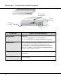
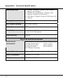
1
© Copyright 2006 Compex Systems Pte Ltd
All Rights Reserved
This document contains information, which is protected by copyright.
Reproduction, adaptation or translation without prior permission is prohibited,
except as allowed under the copyright laws.
Trademark Information
Compex®, ReadyLINK® and MicroHub® are registered trademarks of Compex,
Inc. Microsoft Windows and the Windows logo are the trademarks of Microsoft
Corp. NetWare is the registered trademark of Novell Inc. All other brand and
product names are trademarks or registered trademarks of their respective
owners.
Notice: Copyrights © 2006 by Compex, Inc. All rights reserved. Reproduction,
adaptation, or translation without prior permission of Compex, Inc. is prohibited,
except as allowed under the copyright laws.
Manual Revision by Daniel
Manual Number: U-0490-V1.1C Version 1.1, October 2006
Disclaimer
Compex, Inc. provides this manual without warranty of any kind, either
expressed or implied, including but not limited to the implied warranties of
merchantability and fitness for a particular purpose. Compex, Inc. may make
improvements and/or changes to the product and/or specifications of the
product described in this manual, without prior notice. Compex, Inc will not be
liable for any technical inaccuracies or typographical errors found in this guide.
Changes are periodically made to the information contained herein and will
be incorporated into later versions of the manual. The information contained is
subject to change without prior notice.
Your Feedback
We value your feedback. If you find any errors in this user’s manual, or if you
have suggestions on improving, we would like to hear from you. Please contact
us at:
Fax:
Email:
i
(65) 62809947
[email protected]
FCC NOTICE
This device has been tested and found to comply with the limits for a Class A
digital device, pursuant to Part 15 of the FCC Rules. These limits are designed to
provide reasonable protection against harmful interference in a residential
installation. This device generates, uses and can radiate radio frequency
energy and, if not installed and used in accordance with the instructions, may
cause harmful interference to radio communications. However, there is no
guarantee that interference will not occur in a particular installation. If this
device does cause harmful interference to radio or television reception, the
user is encouraged to try to correct the interference by one or more of the
following measures:
• Reorient or relocate the receiving antenna.
• Connect the computer into an outlet on a circuit different from that to
which the receiver is connected.
• Increase the separation between the computer and receiver.
• Consult the dealer or an experienced radio/TV technician for help.
Caution: Any changes or modifications not expressly approved by the grantee
of this device could void the user's authority to operate the equipment.
FCC Compliance Statement: This device complies with Part 15 of the FCC Rules.
Operation is subject to the following two conditions:
This device may not cause harmful interference, and
This device must accept any interference received, including interference that
may cause undesired operation.
Declaration of Conformity
Compex, Inc. declares the following:
Product Name: Compex 24-Port Gigabit Web-Managed Switch
Model No: GSC2024WM 1a conforms to the following Product Standards:
This device complies with the Electromagnetic Compatibility Directive
(89/336/EEC) issued by the Commission of the European Community.
Electromagnetic Interference (Conduction and Radiation): EN 55022 (CISPR 22)
Electromagnetic Immunity: EN 55024 (IEC61000-4-2,3,4,5,6,8,11)
Power Line Harmonics: EN 61000-3-2 (IEC610000-3-2)
Power Line Flicker: EN 61000-3-3 (IEC610000-3-3)
Product Safety: EN 60950 (IEC60950)
ii
Therefore, this product is in conformity with the following regional standards:
FCC Class A ⎯ following the provisions of FCC Part 15 directive; CE Mark ⎯
following the provisions of the EC directive.
This Class A digital apparatus complies with Canadian ICES-003.
iii
Technical Support Information
The warranty information and registration form are found in the Product CD.
For technical support, you may contact Compex or its subsidiaries. For your
convenience, you may also seek technical assistance from the local distributor,
or from the authorized dealer/reseller that you have purchased this product
from. For technical support by email, write to [email protected].
Refer to the table below for the nearest Technical Support Centers:
U.S.A., Canada, Latin America and South America
Write
Call
Fax
Compex, Inc.
840 Columbia Street, Suite B,
Brea, CA92821, USA
Tel:
+1 (714) 482-0333 (8 a.m.-5 p.m. Pacific time)
Tel:
+1 (800) 279-8891 (Ext.122 Technical Support)
Fax: +1 (714) 482-0332
Europe
Write
Call
Fax
ReadyLINK Networktechnology GmbH
Albert Einstein Straβe 34/M21
63322 Rödermark, Germany
Tel:
+49 (0) 6074 - 98017 (8 a.m.-5 p.m. local time)
Fax:
+49 (0) 6074 - 90668
Email: [email protected]
Asia, Australia, New Zealand, Middle East
and the rest of the World
Write
Call
Fax
Internet
access/
Website:
iv
Compex Systems Pte Ltd
135, Joo Seng Road #08-01, PM Industrial Building
Singapore 368363
Tel:
(65) 6286-1805 (8 a.m.-5 p.m. local time)
Tel:
(65) 6286-2086 (Ext.199 Technical Support)
Fax: (65) 6283-8337
E-mail:
[email protected]
FTPsite: ftp.compex.com.sg
http://www.cpx.com or http://www.compex.com.sg
About This Document
The product described in this document, Compex GSC2024WM is a licensed
product of Compex Systems Pte Ltd. This document contains instructions for
installing, configuring and using Compex GSC2024WM. It also gives an overview
of key applications and networking concepts with respect to the product.
This documentation is for both Network Administrators and the end user who
possesses some basic knowledge in the networking structure and protocols.
It makes a few assumptions that the host computer has already been installed
with TCP/IP and is already up & running and accessing the Internet. Procedures
for Windows 98/2000/XP operating systems are included in this document. For
other operating system, you may need to refer to your operating system’s
documentation for networking.
How to Use this Document
The document is written in such a way that the user will find it convenient to find
specific information pertaining to the product. It comprises of chapters
providing detailed information on the installation and configuration of Compex
GSC2024WM.
Firmware
This manual is written based on Firmware version 2.00.08
Conventions
In this document, special conventions are used to help and present the
information clearly. The Compex 24-Port Gigabit Web-Managed Switch is often
referred to as Compex GSC2024WM in this document. Below is a list of
conventions used throughout.
NOTE
This section will consist of important features or instructions
CAUTION
This section concerns risk of injury, system damage or loss of data
v
WARNING
This section concerns risk of severe injury
References on Menu Command, Push Button, Radio Button, LED and Label
appear in Bold. For example, “Click on Ok.”
vi
Copyrights © 2006 Compex Systems Pte Ltd.................................................................i
Trademark Information ....................................................................................................i
Disclaimer .........................................................................................................................i
Your Feedback.................................................................................................................i
FCC NOTICE .....................................................................................................................ii
Declaration of Conformity..............................................................................................ii
Technical Support Information...................................................................................... iii
About This Document..................................................................................................... v
How to Use this Document ............................................................................................ v
Firmware.......................................................................................................................... v
Conventions.................................................................................................................... v
Chapter 1 Product Overview ........................................................................ 1
1.1 Introduction ............................................................................................................ 1
1.2 Features and Benefits ............................................................................................ 1
Chapter 2 Getting Started ............................................................................. 3
2.1 Packaging Content ............................................................................................... 3
2.2 Setup Considerations ............................................................................................ 4
2.2.1 Hardware Requirements ................................................................................ 4
Chapter 3 Hardware Installation .................................................................. 5
3.1 Desktop installation ............................................................................................... 5
3.2 Rack installation..................................................................................................... 6
Chapter 4 GSC2024WM Utility....................................................................... 8
4.1 GSC2024WM Utility Features – Monitor List ........................................................ 10
4.2 GSC2024WM Utility Features – Device Setting .................................................. 12
4.3 GSC2024WM Utility Features – Tool Menu.......................................................... 14
Chapter 5 Basic Configuration for Compex GSC2024WM ....................... 15
5.1 Accessing the web-based interface ................................................................. 15
5.2 Changing system settings................................................................................... 16
5.3 Configure individual port setting........................................................................ 17
vii
Chapter 6 Advanced Configuration .......................................................... 19
6.1 Network Scenario ................................................................................................ 19
6.1.1 Virtual LAN Configuration ............................................................................ 20
6.1.2 Expand the limitation on bandwidth......................................................... 22
Chapter 7 Monitor your Network ................................................................ 24
7.1
7.2
7.3
7.4
Mirror Control ....................................................................................................... 24
Trap Setting........................................................................................................... 25
System Status........................................................................................................ 27
Port Statistics......................................................................................................... 28
Chapter 8 System Utilities ............................................................................ 29
8.1 Changing Password............................................................................................. 29
8.1.1 Forgot your password?................................................................................. 29
8.2 To backup setting ................................................................................................ 30
8.3 Restore setting...................................................................................................... 31
8.4 Reset setting ......................................................................................................... 31
Chapter 9 Technical Support ...................................................................... 32
Chapter 10 TCP/IP Configuration.................................................................. 33
10.1 For Windows 95/98/98SE/ME/NT ......................................................................... 33
10.2 For Windows XP/2000 .......................................................................................... 35
Appendix I Panel Views and Descriptions................................................... 38
Appendix II Technical Specifications ........................................................... 41
viii
Chapter 1
Product Overview
Chapter 1
Product Overview
1.1
Introduction
The Compex GSC2024WM is a 24-port 10/100/1000Mbps Web-managed
Gigabit Ethernet Switch designed as a high performance solution for
enterprises. It allows legacy LANs to be upgraded to Gigabit LAN, without
wasting the company’s existing investments in hardware, software, and
trained personnel.
The Compex GSC2024WM supports Port-based VLAN for improving
network performance and increasing security. Other advanced features
include Port Mirroring, QoS and Trunking which can be easily configured
from the user-friendly web management interface of the switch.
The Compex GSC2024WM is a high density and high performance
managed switch that caters to all your enterprise’s needs.
1.2
Features and Benefits
Compex GSC2024WM is designed with the following features:
1
•
24 x 10/100/1000Mbps Auto-negotiation Gigabit Ethernet ports
In Compex GSC2024WM, all ports use the N-Way Auto-Negotiation
mechanism to detect the speed of the attached network adapter.
This feature gives users the freedom and convenience of
connecting the switch to a 10Base-T, 100Base-TX or 1000Base-T
network without any manual configuration and setup.
•
Supports port-based VLAN
Compex GSC2024WM can support up to 24 port-based VLAN
groups. It allows the network administrator to separate the network
into several segments by defining which port belongs to which VLAN
segment. This can effectively prevent broadcast and multi-cast
packet flooding of the network. It does not only improve the
network performance, but also provides security between
workgroups.
Chapter 1
Product Overview
•
Supports port-based Quality of Services (QoS)
Compex GSC2024WM supports Quality of Service (QoS) in order to
provide a better service in the network for selected ports. A port
with priority set to High will have its transmitted packets serviced first
at the receiving port.
•
Supports Port Trunking
Up to 4 ports may be defined for Port Trunking, delivering up to
2.4Gbps aggregated bandwidth between two switches.
•
Supports Port-Mirroring
This function allows you to set up a ‘mirror’ port on another specified
port/s, such that you can monitor the received traffic at the
monitored port/s without interrupting the traffic, by replicating it on
the monitoring port.
•
Easy configuration via web-based management interface
Compex GSC2024WM is integrated with an embedded HTTP server,
facilitating the configuration process with a user-friendly web-based
interface. Simply connect Compex GSC2024WM to a workstation
and configure the switch for your network via a Java-enabled web
browser.
Through the web management interface, you can also change the
transmission mode of all ports on the Compex GSC2024WM switch.
This means that you can change the operating mode of any port to
10 Base-T half duplex, 10 Base-T full duplex, 100 Base-TX half duplex,
100 Base-TX full duplex or N-way Auto-negotiation at any time.
2
Chapter 2
Getting Started
Chapter 2
Getting Started
This chapter outlines the basic requirement for the installation of the Compex
GSC2024WM.
2.1
Packaging Content
Thank you for purchasing the Compex GSC2024WM. You will find the
following items in the package:
3
1 x Power Cord
1 x Compex GSC2024WM unit
2 x brackets
8 x screws
4 x rubber feet
1 x Product CD
(Acrobat Reader, User’s Manual and
Utility)
Chapter 2
2.2
Getting Started
Setup Considerations
Before you start:
•
Check your Local Area Network configurations. Check whether it is
using Static IP addressing or dynamic IP allocation.
•
Check whether your PC is equipped with a web browser (Netscape
Navigator, Netscape Communicator or Microsoft Internet Explorer).
2.2.1
Hardware Requirements
•
•
•
4
RJ45 Ethernet cable
Compex GSC2024WM unit
PC equipped with the following:
- Windows 95/98/98SE/2000/NT/ME/XP or
- Any other TCP/IP-enabled operating systems like Mac OS
and UNIX
- Web Browser, such as Microsoft Internet Explorer (4.0 and
above) or Netscape Navigator (4.0 and above)
- GSC2024WM Utility Software provided in the Product CD
Chapter 3
Hardware Installation
Chapter 3
Hardware Installation
Compex GSC2024WM is ideally suitable for office environment usage, and can
be either installed on a flat surface or mounted on a 19-inch rack. The following
steps illustrate how to install the switch.
3.1
5
Desktop installation
1.
Unpack Compex GSC2024WM.
2.
Place it near to a power outlet. Ensure that there is sufficient space
around the unit for heat ventilation and attaching network cables.
3.
The surface on which you place the Compex GSC2024WM should
be clean, smooth, level and sturdy.
4.
Apply the rubber feet to each corner on the bottom of the switch. These
rubber feet can protect the switch from shock/vibration.
5.
Use a RJ45 network cable to connect your PC to any of the ports.
6.
Insert the power cord into the socket located at the back of the
Compex GSC2024WM. Check that the POWER LED on the front
panel of the Compex GSC2024WM has lighted up. The unit is now
ready to use.
Chapter 3
3.2
6
Hardware Installation
Rack installation
1.
Secure the brackets to the holes located on both sides of the
Compex GSC2024WM using the screws provided in the packaging.
2.
After attaching both mounting brackets, align the brackets holes
with the rack holes. Fasten both brackets to the rack using the
screws provided.
3.
Use a RJ45 network cable to connect your PC to any of the ports.
4.
Insert the power cord to the socket located at the back of the
Compex GSC2024WM.
Chapter 3
5.
Hardware Installation
Check that the POWER LED on the front panel of Compex
GSC2024WM has lighted up. The unit is now ready to use.
NOTE
Please allow at least 4 inches of clearance on the front and back
of the switch for proper ventilation. This is especially important for
enclosed rack installation.
7
Chapter 4
GSC2024WM Utility
Chapter 4
GSC2024WM Utility
This utility is specially designed for easy configuration of the Compex
GSC2024WM. It allows you to upgrade your firmware, change your
administrative password, configure your IP address and also access to the webbased interface.
To install this program, simply
1.
Insert the Product CD into your CDROM drive.
2.
Click on the Utility section and the
following screen shot will appear:
3.
Follow the instructions stated on the
screen.
4.
Once
the
installation
has
completed, the following screen
shot will appear. Select Run
GSC2024WM Utility.exe and click on
the OK button to activate the
program.
8
Chapter 4
GSC2024WM Utility
Alternatively, you may also go to Start, Programs, GSC2024WM-1A Utility
and select GSC2024WM-1A Utility to activate the program.
5.
Ensure that your PC is connected to your switch and that it can detect the
switch.
6.
Click on Discovery. Notice that Compex GSC2024WM is detected by this
utility. Select the entry and click on Add to monitor list.
Click on
Discovery
button
Click on
Add to
monitor list
button
9
Chapter 4
4.1
GSC2024WM Utility
GSC2024WM Utility Features – Monitor List
S:
Indicates the system symbol of the device. If a red
box with a cross appears at the “S” column (please
refer to the figure), this shows that the respective
device is either down or working offline.
IP address:
Indicates the current IP address of the device.
MAC address:
Indicates the MAC address of the device.
Protocol Version:
Indicates the version of the utility.
Product name:
Indicates the name of the product.
System name:
Indicates the name of the system. You can appoint a name to your
device in the configuration setting.
Location:
Indicates the location where the device is placed. You can set the
location in the configuration setting.
10
Chapter 4
GSC2024WM Utility
View Trap
The Trap function can receive the events that
happen to the device in the monitor list.
When the light turns green, it indicates that no
trap is being transmitted.
When the light turns red, it indicates that
information is being received.
The “!” indicates that trap events have been detected. This symbol will
disappear after you review and click on the event record.
When you click on View Trap, a Trap Information dialog box will appear.
Please note that in order to receive Trap information, Compex
GSC2024WM has to be configured with Trap IP and Trap Events. Please
refer to Section 7.2 for more details.
11
Chapter 4
GSC2024WM Utility
Add Item
To add a device to the monitor list manually. Simply enter the IP address
of the device that you wish to monitor and click Apply.
Delete Item
Select the device to delete and click on this button.
4.2
GSC2024WM Utility Features – Device Setting
button
You can set your IP address, subnet mask, gateway, etc in this dialog
box. You need to enter the password in order to make the changes. You
can also change your setting from the web-based interface. Kindly refer
to Section 5.2 for details.
12
Chapter 4
GSC2024WM Utility
button
If you forgot your password, you would need to reset your settings to their
default value by pressing the button located at the back of the switch.
Also, if you press the reset button, all settings will be returned to their
default value and your current configuration will be erased. For details on
changing password using the web-based interface, kindly refer to
Section 8.1.
button
You can upgrade your firmware version using this utility. Simply select the
firmware file from your respective folder, enter the password and click on
the Start button.
button
You can simply double click on the device in the monitor list, or select it
and click on Web Access to proceed to the authentication page of the
Compex GSC2024WM.
13
Chapter 4
4.3
GSC2024WM Utility
GSC2024WM Utility Features – Tool Menu
File Menu
Monitor save:
Record the settings of the monitor list.
Monitor save as:
Record the settings of the monitor list in appointed
filename and path.
Monitor load:
Manually load the setting file of the monitor list.
View Menu
View log:
Show the events detected by the utility and the device.
Clear log:
Clear the log data.
Option Menu
Refresh time:
Select the time frequency for monitoring the
device.
Help Menu
About:
Shows the version number of the Utility and
Protocol.
14
Chapter 5
Basic Configuration for Compex GSC2024WM
Chapter 5
Basic Configuration for Compex GSC2024WM
Compex GSC2024WM eases the configuration process with a user-friendly webbased interface. This chapter elaborates on how to set up the Compex
GSC2024WM when you use the web-based configuration interface.
This chapter will cover the following:
• Accessing the web-based interface
• Changing system settings such as IP address, subnet mask and gateway
• Naming your switch and location
• Setting duplex mode, speed of connection and the port priority
5.1
Accessing the web-based interface
You can use GSC2024WM Utility (refer to Section 4.2) to access to this
authentication page.
Alternatively, you may also access to the web-based interface by
entering the URL address, http://192.168.100.128 in the address bar of
your Internet browser.
Once the authentication page appears as shown below, type in the
default password as password (in lower-case) and click on the Login
button. Please note that the password is case-sensitive.
15
Chapter 5
Basic Configuration for Compex GSC2024WM
The main page will be displayed as shown. You may scroll down to view
the status of different functions, such as connectivity, speed of individual
ports, port trunking, VLANs, duplex mode, etc.
5.2
Changing system settings
IP address configuration is for configuring IP address of the management
board in the switch. It is likely that several VLANs are on the single switch,
and each VLAN can be regarded as an independent network, so their
network addresses may be different. In order that each end-station
connected to switch port can access the management system, multiple
IP addresses are needed for the management board.
Simply go to Misc Operation in the menu
and select System Setting as shown in the
figure at the right hand side.
16
Chapter 5
Basic Configuration for Compex GSC2024WM
Next, you may set a switch name and
location
for
your
Compex
GSC2024WM for easy identification.
The default IP address for Compex
GSC2024WM is 192.168.100.128. To
change it, simply enter the new IP
address, subnet mask and the IP
address of the gateway, and click on
Apply to update the changes.
5.3
Configure individual port setting
To set the duplex mode, flow control and
port priority, simply go to Port Configuration in
the main menu. The overall port settings will
appear as shown in the figure on the right.
Simply click on one of the port IDs and its settings will appear.
Speed:
17
Chapter 5
Basic Configuration for Compex GSC2024WM
This option allows you to work in either forced or auto mode. When
Compex GSC2024WM is set to forced mode (10M/100M), the auto-MDIX
function will be disabled.
This means that you will be required to use the appropriate Ethernet RJ45
cable to connect your devices: a straight-through MDI Ethernet RJ45
cable to connect your PC to Compex GSC2024WM; or a crossover MDIX
Ethernet RJ45 cable to connect your Compex GSC2024WM to your hub.
On the other hand, if you set the speed to Auto, you will can use any
Ethernet RJ45 cable with any devices since the auto-MDIX function will
have been activated.
Flow Control:
This feature reports the flow control settings of the port. Enabling the flow
control function limits the amount of traffic which crosses the switch.
QoS:
Quality of Service (QoS) refers to the capability of a network to provide a
better service to selected ports in the switch. A port with priority set to
High will have its transmitted packets serviced first at the receiving port.
The example above illustrates
that Port 24 is set to high
priority; and Port 1 and 2 are
in normal priority. When Port 2
and 24 send packets to Port 1
at the same time, the packet
from Port 24 will be serviced
first by Port 1 as a higher
priority was given to Port 24.
18
Chapter 6
Advanced Configuration
Chapter 6
Advanced Configuration
Compex GSC2024WM allows you to separate the network into small segments
for easy management. This not only improves the network performance, but
also provides security between workgroups. Besides that, bandwidth increment
can also be done between cascaded switches.
This chapter will cover the following:
• Setting Virtual Local Area Network (VLAN)
• Expanding the limitation on bandwidth for cascaded switches
6.1
Network Scenario
In a company, two LAN segments are implemented on switch, S1. A
printer shared between both Accounts and Sales departments is
physically located at the Sales Department. To allow the users in
Accounts department to access the printer, you can simply create the
printer as a member of both the Sales and the Accounts Departments
using VLAN.
Figure 6.1a VLAN in a network
19
Chapter 6
6.1.1
Advanced Configuration
Virtual LAN Configuration
In a VLAN, all end-stations communicate with each other as if
they were in the same local LAN although they may be not on
the same physical network segment. However, all data packets
in a VLAN are constrained to the VLAN so end stations in
different VLANs cannot communicate with each other directly.
Compex GSC2024WM supports port-based VLAN, i.e. the VLAN is
specified by selecting a group of ports belonging to the VLAN.
Now, we are going to illustrate how to set up a VLAN with
Compex GSC2024WM.
From the main menu of the web-based interface of Compex
GSC2024WM,
20
1.
Click on VLAN configuration. As you can see from the figure
shown below, all ports are configured in VLAN 01 by default.
2.
Select ID 01 to edit the members in the VLAN ID 01.
3.
Give a description for your VLAN ID 01. Select which ports
should belong to this VLAN, In our example, we set Port 3 to
Port 9 as the members of ID 01. Notice that port 9, which is
connected to the printer, is also set in this VLAN ID.
Chapter 6
21
Advanced Configuration
4.
Click on Apply and proceed to configure VLAN 02.
5.
Give a description, such as Sales Dept, to identify your VLAN.
6.
Select which ports should belong to this VLAN. In our
example, we set Port 9 to Port 13 as the members of VLAN ID
02. Note that we also need to include Port 9 in this VLAN.
7.
Click on Apply. Now, you can see the VLANs which have
been configured. Notice that port 9 (connected to the
shared printer) is a member of both VLANs.
Chapter 6
6.1.2
Advanced Configuration
Expand the limitation on bandwidth
We define Port Trunking as the ability to group a set of ports into
a single logical link. This is an inexpensive method to increase
throughput between switches. The port trunk acts as single link
between switches. It does not create a loop even though the
ports are physically connected.
From the figure shown below, S1 is connected to S2 through Ports
1 and 2; S2 is connected to S3 via Ports 9,10,11 and 12. We need
to increase the bandwidth of these three-cascaded switches in
order to allow all members to have faster access to the file server.
This can be done by using Port Trunking Configuration.
22
Chapter 6
Advanced Configuration
We explain how to configure port trunking using the example
illustrated above.
For S1
1.
Go to the main menu of the web-based interface of
Compex GSC2024WM, select Trunk Configuration.
2.
Select Port 01 and 02 as members of Trunk ID 01.
3.
Click on Apply to update the changes.
For S2
1.
Select Port 01 and 02 as members of Trunk ID 01; and Port 09,
10, 11, 12 as members of Trunk ID 02.
2.
Click on Apply to update the changes.
For S3
1.
Select Port 09, 10, 11, and 12 as members of Trunk 02.
2.
Click on Apply to update the changes.
Once the trunking configuration for the three switches has been
done, you will notice that the speed of transmission will be much
faster than before.
23
Chapter 7
Monitoring Your Network
Chapter 7
Monitor your Network
This chapter will cover the following:
• Duplicating copies of incoming packets and forward to a monitoring port
• Monitoring Trap
• Viewing the statuses of individual functions
7.1
Mirror Control
This function allows you to set up a ‘mirror’ port of any specified port/s,
such that you can monitor the incoming and/or outgoing traffic at the
monitored port/s without interrupting the client/s on the monitored port/s.
A network administrator can use port mirroring as a diagnostic tool or
debugging feature.
From the figure, Port 23 is configured as the sniffer port and port 1 is set as
the source port. This means that using the PC attached to Port 23 , the
network administrator is able to keep a close track of the data traffic at
Port 1.
Once we set Port 1 (for example) as the source port, a duplicate copy of
each packet that is being sent and/or received via Port 1 will also be
forwarded to Port 23.
24
1.
Select Mirror Configuration from the main page.
2.
Choose which packets to monitor by selecting either Rx (Receive),
Tx (Transmit) or Both (Received and transmit) from the pull down
menu.
3.
Choose Port 23 as the Sniffer Port. This is the port to which the
monitored packets will be forwarded.
Chapter 7
Monitoring Your Network
4.
Next, select the Port 1 as the source port whose activities you want
to monitor.
5.
Click on the Apply button to update the changes.
To monitor more ports, repeat step 4 and click on the Apply button to
update the changes.
7.2
Trap Setting
Trap setting allows you to select the types of events of which you would
like to be alerted. When Compex GSC2024WM encounters the selected
events in the network, it will send the information to the Trap IP address
configured in the setting. The PC from which you will view the trapped
events must run the GSC2024WM Utility to be able to monitor and
capture any trapped information. For details on how to use the
GSC2024WM Utility, please refer to Section 4.1.
1.
25
Enter the IP address of the PC from which you will view the trap
events in the Trap IP and select the types of events you wish to
monitor.
Chapter 7
Monitoring Your Network
System Events – If you select:
- Device Bootup: A trap will be activated when the switch boots up.
- Illegal Login: A trap will be activated if an incorrect password is
entered at the login, the switch will also record the IP address from
which the unsuccessful login was attempted.
2.
26
Click Apply to update changes.
Chapter 7
7.3
Monitoring Your Network
System Status
This option allows you to view the switch and port status; the VLAN
settings; the port trunking settings and the port mirror settings. You may
click on the Refresh to renew the posted information.
27
Chapter 7
7.4
Monitoring Your Network
Port Statistics
This option will show you detailed information on individual ports, such as
the total number of packets received or transmitted, the size of the
packets and any errors found while transmitting or receiving.
28
Chapter 8
System Utilities
Chapter 8
System Utilities
This chapter will cover the following:
• Changing your password
• Backing up your configuration
• Restoring your configuration
• Reset your switch’s setting
8.1
Changing Password
You can amend your current administrative password through this webbased interface, or proceed to our GSC2024WM Utility (Refer to Chapter
5).
8.1.1
Forgot your password?
If you forget your password, you can reset it back to its default
value by simply pressing the Reset button located at the back of
your Compex GSC2024WM.
Please bear in mind that, once this button is pressed, all your
current configuration, including the VLANs, IP address, Port
Trunking, Port Mirroring will be set back to factory default.
At this moment, remember that backing up your configuration
plays an important role. Kindly refer to the next section for details
on creating a backup of your settings and on restoring your
saved settings.
29
Chapter 8
8.2
System Utilities
To backup setting
This backup tool assists you in saving your current configuration.
30
1.
Simply go to the main menu,
select Misc Operation, and
choose Backup Setting. The
following screen shot will
appear:
2.
Click on Backup and save your file
in a specific directory on your hard
disk.
Chapter 8
8.3
System Utilities
Restore setting
Restore Setting allows you to load your saved configuration back to your
Compex GSC2024WM.
8.4
1.
Click on Browse… to select the configuration file that was previously
saved in your directory.
2.
Once you have confirmed the correct file to be restored, click on
Restore.
Reset setting
Reset setting allows you to reset the device back to its default factory
settings. Be aware that the entire configuration will be reset; the IP
address of the device will be set to default setting 192.168.0.1 and the
password to password.
31
Chapter 9
Technical Support
Chapter 9
Technical Support
You may refer to the Compex technical center nearest to you as shown below:
32
Chapter 10
TCP/IP Configuration
Chapter 10
TCP/IP Configuration
To enable your PC to communicate with the switch, you need to assign an IP
address to your PC so that it will be in the same subnet as Compex
GSC2024WM. By default, Compex GSC2024WM’s IP address is 192.168.100.128;
subnet mask is 255.255.255.0. You need to configure your PC’s IP address to
192.168.100.xxx; and subnet mask is 255.255.255.0, where xxx is any number from
1 to 254 excluding 128. Simply follow the procedures stated below to configure
the TCP/IP settings of your PC.
10.1 For Windows 95/98/98SE/ME/NT
Please note the following TCP/IP configurations are based on Windows
98.
33
1.
From your desktop, choose Network Neighborhood icon and select
Properties.
2.
Choose the network adapter that you are using; right click and
select Properties.
3.
From the Network window, go to
your TCP/IP option and click on
the Properties button.
Chapter 10
34
TCP/IP Configuration
4.
Select the radio button for Specify
an IP address.
5.
Enter the IP Address and Subnet
Mask as 192.168.100.xxx and
255.255.255.0, where xxx can be
any number from 1 to 254
excluding 128. In this example, we
are using 192.168.100.160 as the
static IP Address.
6.
Press OK to close all windows and allow your computer to reboot.
7.
When the PC has rebooted, you may wish to check whether the IP
address was assigned correctly to it. Simply go to the Start menu,
select Run, and type winipcfg.
8.
Select your network adapter from the drop-down list and click OK.
Chapter 10
TCP/IP Configuration
10.2 For Windows XP/2000
35
1.
Go to your desktop, click on My Network Places icon and select
Properties.
2.
Go to your network adapter icon, right click and select to
Properties.
3.
Proceed to Internet Properties (TCP/IP) and click on the Properties
button.
Chapter 10
36
TCP/IP Configuration
4.
Select the radio button for Use the following IP address. Enter the IP
Address and Subnet Mask as 192.168.100.xxx and 255.255.255.0,
where xxx can be any number from 1 to 254 excluding 128.
5.
Ensure that the radio button for Obtain DNS sever address
automatically is selected.
6.
Click on Ok to close all windows.
Chapter 10
7.
37
TCP/IP Configuration
Next, you may check if the IP address was correctly assigned to your
PC. Go to Start menu, Accessories, select Command Prompt and
execute the command ipconfig/all.
Appendix I
Panel Views and Descriptions
Appendix I
Panel Views and Descriptions
In this appendix, we will describe the LED indications and descriptions.
Features
POWER LED
SYSTEM LED
Link/ACT LED
38
Status and Indication
Steady Green
Power is supplied to the device.
Off
No power is supplied to the device.
Steady Green
The device is ready to operate.
Off
The device is either not powered up or a
problem might have occurred.
Steady Green
The respective port has successfully
connected to Compex GSC2024WM.
Blinking
The respective port is transmitting or
receiving data.
Off
No connection is established to Compex
GSC2024WM.
Appendix I
Panel Views and Descriptions
Features
1000Mbps LED
Status and Indication
Steady Green
The respective port is connected at the
speed of 1000Mbps.
Off
•
•
No network connection is established
to Compex GSC2024WM, or
The respective port is connected at
the speed of 10Mbps or 100Mbps.
When both 100Mbps and 1000Mbps LEDs
do not light up, this means that the switch
is operating at the speed of 10Mbps.
100Mbps LED
Steady Green
The respective port is connected at the
speed of 100Mbps.
Off
•
•
No network connection is established
to Compex GSC2024WM, or
The respective port is connected at
the speed of 10Mbps or 1000Mbps.
When both 100Mbps and 1000Mpbs LEDs
do not light up, this means that the switch
is operating at the speed of 10Mbps.
39
Appendix I
Panel Views and Descriptions
AC power
connector
Power
switch
Reset
button
Features
Status and Indication
24 RJ45 ports
Supports
• Auto negotiable 10/100/1000Mbps
• Auto MDI/MDIX crossover detection function.
Reset button
Reset settings to factory default. Kindly note that
you need to make regular backups of your
configuration. Once you have pressed the reset
button, Compex GSC2024WM will set all settings
back to their default values.
AC power connector
Supports input voltages range from 100 to 240 VAC
at 50-60Hz.
Power switch
Activate or deactivate power supplied to Compex
GSC2024WM.
40
Appendix II Technical Specifications
Appendix II Technical Specifications
Network Protocol, Standards and Electrical Emissions
Industry Standards
Complies with
• IEEE 802.3 10Base-T
• IEEE 802.3u 100Base-TX
• IEEE 802.3ab 1000Base-T
• IEEE 802.3x Flow Control
Safety Certifications
•
•
•
•
Network Protocol
CSMA/CD
CE Mark
FCC Class A
Gost
UL
Interface Options
24 RJ45 Ports
24 x 10/100/1000Mbps Auto MDIX RJ45 ports
Network Cables
•
•
•
10 Base-T: 2-pair UTP Cat 3,4,5; up to 100m
100 Base-TX: 2-pair UTP Cat 5; up to 100m
1000 Base-T: 4-pair UTP Cat 5; up to 100m
Network Management
In Band and Out of Band
•
•
Web-based HTTP
Port Mirroring
Performance
Transmission Method
41
Store and Forward
Appendix II Technical Specifications
Data Transfer Rate
•
•
•
10 Base-T Ethernet: 10Mbps (Half Duplex);
20Mbps (Full Duplex)
100Base-TX Fast Ethernet: 100Mbps (Half
Duplex); 200Mbps (Full Duplex)
1000 Base-T Gigabit Ethernet: 2000Mbps (Full
Duplex)
Filtering Address Table
8K entries per switch
MAC Address Learning
Automatic update
RAM Buffer
512K bytes per switch
Virtual LAN
•
•
Priority Queuing
2 levels
Port-based VLAN
Up to 24 VLAN groups
Physical and Environment
Environmental
Requirements
Operating temperature
Storage temperature
Operating humidity
Storage humidity
RH = Relative Humidity
Physical Dimension
440mm x 210mm x 44mm (W x H x D)
Power Consumption
Maximum of 35 Watts
AC Inputs
100-240V AC, 50/60
42
: 0ºC to 40ºC
: -10ºC to 70ºC
: 10% to 90% RH
: 5% to 90% RH