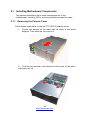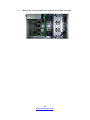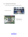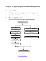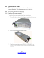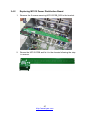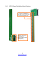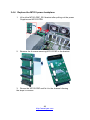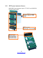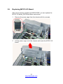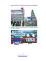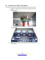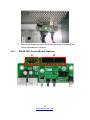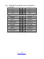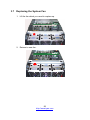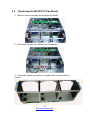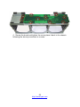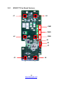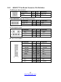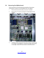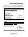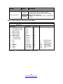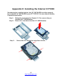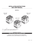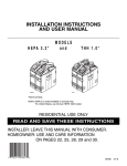
1
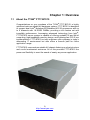
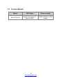
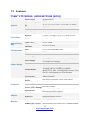
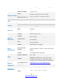
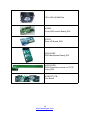
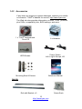
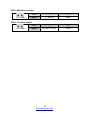
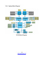
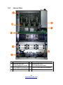
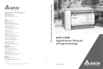
TYAN® FT77 B7015 Service Engineer’s Manual 1 http://www.tyan.com 2 http://www.tyan.com PREFACE Copyright This publication, including all photographs, illustrations, and software, is protected under international copyright laws, with all rights reserved. Neither this manual, nor any material contained herein, may be reproduced without written consent of manufacturer. Copyright 2010 MiTAC International Corporation. All rights reserved. ® TYAN is a registered trademark of MiTAC International Corporation. Version 1.1 Disclaimer Information contained in this document is furnished by MiTAC Computer Corporation and has been reviewed for accuracy and reliability prior to ® printing. TYAN assumes no liability whatsoever, and disclaims any ® express or implied warranty, relating to sale and/or use of TYAN products including liability or warranties relating to fitness for a particular purpose or ® merchantability. TYAN retains the right to make changes to produce descriptions and/or specifications at any time, without notice. In no event ® will TYAN be held liable for any direct or indirect, incidental or consequential damage, loss of use, loss of data or other malady resulting from errors or inaccuracies of information contained in this document. Trademark Recognition All registered and unregistered trademarks and company names contain-ed in this manual are property of their respective owners including, but not limited to the following. ® TYAN is a trademark of MiTAC Computer Corporation. ® Intel is a trademark of Intel Corporation. ® ® AMI , AMIBIOS and combinations thereof are trademarks of AMI Technologies. ® ® Microsoft , Windows are trademarks of Microsoft Corporation. ® Winbond is a trademark of Winbond Electronics Corporation. Portable Document Format (PDF) is a trademark of Adobe Corporation. 3 http://www.tyan.com FCC Declaration Notice for the USA Compliance Information Statement (Declaration of Conformity Procedure) DoC FCC Part 15: This device complies with part 15 of the FCC Rules This device complies with Part 15 of the FCC Rules. Operation is subject to the following conditions: ·This device must not cause harmful interference. ·This device must accept any interference received, including interference that may cause undesirable operation. This equipment has been tested and found to comply with the limits for a Class A digital device, pursuant to Part 15 of the FCC Rules. These limits are designed to provide reasonable protection against harmful interference when the equipment is operated in a commercial environment. This equipment generates, uses, and can radiate radio frequency energy and, if not installed and used in accordance with the instruction manual, may cause harmful interference to radio communications. Operation of this equipment in a residential area is likely to cause harmful interference in which case the user will be required to correct the interference at his own expense. Notice for Canada This Class A digital apparatus complies with Canadian ICES-003. Cet appareil numérique de la Classe A est conforme à la norme NMB-003 du Canada. Notice for Europe (CE Mark) This product is in conformity with the Council Directive 2004/108/EC. CAUTION: Lithium battery included with this board. Do not puncture, mutilate, or dispose of battery in fire. There will be danger of explosion if battery is incorrectly replaced. Replace only with the same or equivalent type recommended by manufacturer. Dispose of used battery according to manufacturer instructions and in accordance with your local regulations. 4 http://www.tyan.com About this Manual This manual provides you with instructions on installing your FT77-B7015. This Manual is intended for experienced users and integrators with hardware knowledge of personal computers. This manual is consisted of the following parts: Chapter1: Provides an introduction to the FT77-B7015 bare-bones, standard parts list, describes the external components, gives a table of key components, and provides block diagrams of the system. Chapter2: Covers procedures on installing the CPU, memory modules, add on card and hard drives. Chapter3: Covers removal and replacement procedures for pre-installed components. Appendix : Describes the differences between motherboard BIOS and system BIOS; introduces how to install the internal HDD, list the cable connection and FRU part tables for reference of system setup; and technical support in case a problem arises with your system. For information on the mainboard, please refer to the attached mainboard user’s manual. You can find the detailed description about jumper and BIOS settings from the mainboard manual. 5 http://www.tyan.com SAFETY INFORMATION Before installing and using FT77-B7015, take note of the following precautions: ·Read all instructions carefully. ·Do not place the unit on an unstable surface, cart, or stand. ·Do not block the slots and opening on the unit, which are provided for ventilation. ·Only use the power source indicated on the marking label. If you are not sure, contact the power company. ·The unit uses a three-wire ground cable, which is equipped with a third pin to ground the unit and prevent electric shock. Do not defeat the pur-pose of this pin. If you outlet does not support this kind of plug, contact your electrician to replace your obsolete outlet. ·Do not place anything on the power cord. Place the power cord where it will not be in the way of foot traffic. ·Follow all warnings and cautions in this manual and on the unit case. ·Do not push objects in the ventilation slots as they may touch high volta-ge components and result in shock and damage to the components. ·When replacing parts, ensure that you use parts specified by the manuf-acturer. ·When service or repairs have been done, perform routine safety checks to verify that the system is operating correctly. ·Avoid using the system near water, in direct sunlight, or near a heating device. ·Cover the unit when not in use. 6 http://www.tyan.com Table of Contents Chapter 1: Overview ......................................................................9 1.1 About the TYAN® FT77-B7015................................................ 9 1.2 Product Models......................................................................10 1.3 Features ................................................................................11 1.4 Standard Parts List ................................................................13 1.4.1 Box Contents ..................................................................13 1.4.2 Accessories ....................................................................15 1.5 Optional Parts........................................................................16 1.6 About the Product..................................................................17 1.6.1 System Front View .........................................................17 1.6.2 System Rear View ..........................................................17 1.6.3 LED Definitions...............................................................18 1.6.4 Motherboard Layout .......................................................19 1.6.5 Jumpers & Connectors ...................................................20 1.6.6 System Block Diagram ...................................................25 1.6.7 Internal View...................................................................26 Chapter 2: Setting Up..................................................................27 2.0.1 Before you Begin ............................................................27 2.0.2 Work Area.......................................................................27 2.0.3 Tools ...............................................................................27 2.0.4 Precautions.....................................................................28 2.1 Installing Motherboard Components .....................................29 2.1.1 Removing the Chassis Cover.........................................29 2.1.2 Installing the CPU and Heat sink....................................31 2.1.3 Installing the Memory .....................................................34 2.1.4 Installing Expansion Cards.............................................37 2.1.5 Installing Hard Drives .....................................................39 2.2 Rack Mounting.......................................................................40 2.2.1 Installing the Server in a Rack........................................40 2.2.2 Installing the inner Rails to the Chassis .........................41 2.2.3 Installing the Outer Rails to the Rack .............................42 2.2.4 Rack mounting the Server..............................................42 Chapter 3: Replacing Pre-Installed Components .....................45 3.1 Introduction ..........................................................................45 3.2 Disassembly Flowchart........................................................45 3.3 Removing the Cover ............................................................46 3.4 Replacing the Power Supply ...............................................46 3.4.1 Replace the power supply ..............................................46 7 http://www.tyan.com 3.4.2 Replacing M7015 Power Distribution Board.................47 3.4.3 M7015 Power Distribution Board Features ..................48 3.4.4 Replace the M7015 power backplane ..........................49 3.4.5 M7015 power backplane Features ...............................50 3.5 Replacing M7015 I/O Board ..................................................51 3.6 Replacing the LED Control Board .........................................53 3.6.1 M1008 LED Control Board Features ............................54 3.6.2 M1008 LED Control Board Connector Pin Definition ...55 3.7 Replacing the System Fan ....................................................56 3.8 Replacing the M1801F77-Fan Board....................................57 3.8.1 M1801F77-Fan Board Features ...................................59 3.8.2 M1801F77 Fan Board Connector Pin Definition...........60 3.9 Removing the Motherboard .................................................61 Appendix I: BIOS Differences.....................................................63 Appendix II: Installing the Internal 3.5”HDD..............................65 Appendix III: Cable Connection Tables .....................................67 Appendix IV: FRU Parts Table ....................................................69 Appendix V: Technical Support .................................................71 8 http://www.tyan.com Chapter 1: Overview 1.1 About the TYAN® FT77-B7015 ® Congratulations on your purchase of the TYAN FT77-B7015, a highly optimized rack-mountable 4U barebone system. FT77-B7015 is designed ® to support dual Intel Nehalem-EP/Nehalem-WS 2S processors and up to 6 channels with 18 DDR3 DIMMs, providing a rich feature set and ® incredible performance. Leveraging advanced technology from Intel , FT77-B7015 server system is capable of offering scalable 32 and 64-bit computing, high-bandwidth memory design, and lightning-fast PCI-E bus implementation. FT77-B7015 not only enpowers your company in today’s demanding IT environment but also offers a smooth path for future application usage. FT77-B7015 uses rack-mountable 4U chassis featuring a robust structure and a solid mechanical enclosure. All of this provides FT77-B7015 the power and flexibility to meet the needs of nearly any server application. 9 http://www.tyan.com 1.2 Product Models Model HDD Bays Power supply B7015F77V2R Support 2 internal 2.5” SATAII HDD 3600W(1200Wx3) PWR supply 10 http://www.tyan.com 1.3 Features TYAN® FT77B7015 (B7015F77V2R [BTO]) System Front Panel Internal Drive Bay Form Factor Chassis Model Dimension (D x W x H) Motherboard Board Dimension Gross Weight Buttons LEDs I/O Ports Type / QTY Supported HDD Interface System Cooling FAN Configuration Type Efficiency Serviceability Input Range Power Supply Frequency Output Watts Processor Chipset Memory 4U Rackmount FT77 31.31" x 17.24" x 6.93" (770 x 438 x 176mm) S7015-CA 16"x19" (406.4x482.6mm) 29 kg (1) RST / (1) NMI / (1) ID / (1) PWR w/ LED (1) PWR / (1) HDD / (1) Warning (2) USB ports (2) 2.5" fixed SATA-II 3.0Gb/s (3+3) 12cm redundant fans ERP1U PFC Hot-swap 100-127V AC (Low-Line Voltage) / 200-240V AC (High-Line Voltage) 60 Hertz 2400W [(2+1) 2400W @200-240V], Max. 12Vdc@ 199.6A / 3000W [3 x1000W @100-127V], Max. 12Vdc@ 249.6A; Note: Only one AC inlet allowed per circuit breaker (8) 2x4-pin & (8) 2x3-pin auxiliary 12V power cables included GPU Power Connectors Supported CPU Intel Xeon Processor 5500/ 5600 Series Series Socket Type / Q'ty LGA1366 / (2) Thermal Design Max up to 130W Power (TDP) wattage Up to 4.8/ 5.86/ 6.4GT/s with Intel QuickPath System Bus Interconnect (QPI) support IOH / ICH Intel (2) 5520 / ICH10R Super I/O Winbond W83627DHG-P PCI-E Switch PLX PEX8647(4) Supported DIMM Qty (9)+(9) DIMM slots DIMM Type / Speed DDR3/DDR3L 800/1066/1333* RDIMM/UDIMM 11 http://www.tyan.com Capacity Memory channel Memory voltage PCI-E Expansion Slots Max. HBA Dimension (H x L) PCI Port Q'ty LAN Controller Connector type Graphic Resolution Chipset USB I/O Ports VGA RJ-45 Chipset Voltage System Monitoring Temperature LED Others Onboard Chipset Server Management AST2050 IPMI Feature AST2050 iKVM Feature Brand / ROM size BIOS Operating System Regulation Operating Environment Feature Up to 144GB at launch w/ dual rank RDIMMs 3 Channels per CPU 1.5V or 1.35V (2) PCI-E x16 slots (w/ x4 link) / (8) PCI-E Gen.2 x16 slots / (2) PCI-E Gen.2 x1 slots (13) 111.15mm x 312.00mm (FH/FL) (1) PCI 32-bit slot (4) Intel 82574L D-Sub 15-pin 1600x1200 Aspeed AST2050 (2) ports (1) D-Sub 15-pin port (4) ports Winbond W83793G Monitors voltage for CPU, memory, chipset & power supply Monitors temperature for CPU & system environment Fan fail LED indicator / Over temperature warning indicator Watchdog timer support Onboard Aspeed AST2050 IPMI 2.0 compliant baseboard management controller (BMC) / USB 2.0 virtual hub / BIOS update 24-bit high quality video compression / Dual 10/100 Mb/s MAC interfaces AMI / 4MB Plug and Play (PnP) /PCI2.3 /WfM2.0 /SMBIOS2.3 /PXE boot / ACPI 2.0 power management /Power on mode after power recovery / User-configurable H/W monitoring OS supported list Please refer to our OS supported list. FCC (DoC) CE (DoC) Operating Temp. Non-operating Temp. Class A Yes 5° C ~ 55° C (41° F~ 131° F) - 40° C ~ 70° C (-40° F ~ 158° F) 12 http://www.tyan.com RoHS Package Contains 1.4 In/Non-operating Humidity RoHS 6/6 Complaint Barebone Manual Installation CD 90%, non-condensing at 35° C Yes (1) FT77B7015 Barebone (1) User's manual ® (1) TYAN installation CD Standard Parts List This section describes FT77-B7015 package contents and accessories. Open the box carefully and ensure that all components are present and undamaged. The product should arrive packaged as illustrated below. 1.4.1 Box Contents Component Description 4U FT77 Chassis Main Board,S7015-CA 1200W Power Supply 13 http://www.tyan.com 120 x120 x38 MM Fan M1008 Front LED control Board_R03 M7015 Rear I/O Board_R02 M7015-PBP PWR Backplane Board_R01 M7015-PDB PWR Distribution board for PCI-E Card_R02 M1801F77-FB Fan Board 14 http://www.tyan.com 1.4.2 Accessories If any items are missing or appear damaged, contract your retailer ® or browse to TYAN ’s website for service: http://www.tyan.com. ® The Web site also provides information on other TYAN products, plus FAQs, compatibility lists, BIOS settings, and more. ® 1 x TYAN Motherboard Drive CD 2 x Heatsink HDD Screws Power Cables Left to right: Europe, US Mounting Ears & Screws Barebone Manual Rail Kit Rail with Bracket x 2 15 http://www.tyan.com Screw Sack 1.5 Optional Parts Item Model Number HDD Bracket CHDT-0150 Picture Quantity Description 1 3.5" HDD Bracket 16 http://www.tyan.com 1.6 About the Product The following views show you the product. 1.6.1 System Front View USB ports ID button Power button (with LED) Warning LED NMI button HDD LED Reset button 1.6.2 System Rear View VGA Port Power supply LAN Port ID LED USB Port Expansion slots 17 http://www.tyan.com 1.6.3 LED Definitions Front Panel LED Power LED HDD LED Warning LED Rear I/O LED LED RJ-45 Linkage/ Activity(Left) RJ-45 Linkage/ Activity(Right) State Color On Off Off Blinking Green Off Off Green On Red State On Blinking Off On On Off Description System is turned on Power off HDD not active HDD active Fan fail/PSU fail/Over temperature/Over voltage Color Green Green Off Amber Green Off Description 10Mb/100Mb/1000Mb linked 10Mb/100Mb/1000Mb activity No LAN linked 1000Mb linked/ activity 100Mb linked/activity 10Mb mode or No LAN linked NOTE: “Left” and “Right” are viewed from the rear panel. ID LED LED ID LED State On Off Color Blue Off Description System identified System not identified Note: Press ID button when the system is AC (Alternating Current) on, then ID LED will show the system is identified with emitting blue light. Users from remote site could also activate ID LED by input a few commands in IPMI, detailed software support please visit http://www.tyan.com for latest AST2050 user guide. 18 http://www.tyan.com 1.6.4 Motherboard Layout The diagram is representative of the latest board revision available at the time of publishing. The board you receive may not look exactly like the above diagram. 19 http://www.tyan.com 1.6.5 Jumpers & Connectors Jumper/Connector Function CN17/CN20 COM port CN18 Board-to-Board Receptacle connector CN19 USB header CN43 Front Panel header CN36/CN37/CN40 FAN connector CN101 Clear CMOS CN61 System Intrusion header CN73 NMI button header CN74 ID button header 20 http://www.tyan.com Jumper Placement CN40 CN43 CN19 CN20 CN37 CN36 CN18 CN17 CN43: Front Panel header Pin 1 2 3 4 5 6 7 8 9 10 11 12 13 14 Pin_1 15 Signal GND PW_LED+ PW_LEDWLED+ HDD_LED+ GND PWR_SW# P3V3_SB RST_SW# GND SDA SCL GND RXD TXD 21 http://www.tyan.com CN18: Board-to-Board Receptacle connector Signal GND RED GND GREEN GND BLUE GND HSYNC VSYNC GND DDC_DATA DDC_CLK GND NC Vcc5_VGA NC GND GND GND GND Pin 1 3 5 7 9 11 13 15 17 19 21 23 25 27 29 31 33 35 37 39 Pin 2 4 6 8 10 12 14 16 18 20 22 24 26 28 30 32 34 36 38 40 Signal GND USB0USB0+ GND USB1USB1+ GND USB2USB2+ GND USB3USB3+ GND NC Vcc_USB Vcc_USB Vcc_USB Vcc_USB Vcc_USB Vcc_USB CN19: USB header Pin_1 Pin 1 2 3 4 5 6 7 8 9 10 Signal VCC_USB USB6USB6+ GND GND VCC_USB USB7USB7+ GND GND CN36/ CN37/ CN40: FAN connector Pin 1 2 3 4 5 6 Signal GND P12V TACH PWM GND P12V 22 http://www.tyan.com CN73 CN61 CN74 CN101 CN101: Clear CMOS Pin_3 Pin_1 Normal (Default) Pin_3 Pin_1 Clear CMOS You can reset the CMOS settings by using this jumper if you have forgotten your system/setup password or need to clear system BIOS setting. Power off system and disconnect both power connectors from the motherboard Put jumper cap back to Pin_1 and Pin_2 (default setting) Use jumper cap to close Pin_2 and Pin_3 for several seconds to Clear CMOS Reconnect power and power on system CN61: System Intrusion header Pin_1 Pin 1 2 Signal GND INTRUDER_N 23 http://www.tyan.com CN73: NMI button header Pin_1 Pin 1 2 Signal FP_NMI_N GND Pin 1 2 Signal ID_BUTTON_N GND CN74: ID button header Pin_1 24 http://www.tyan.com 1.6.6 System Block Diagram S7015 Block Diagram 25 http://www.tyan.com 1.6.7 Internal View ⑧ ⑤ ① ⑥ ② ④ ⑦ ③ ① ② ③ ④ S7015-CA Main Board M7015-PDB_R02 PWR Distribution board M1008_R03 Front LED control Board System Fans ⑤ ⑥ Power Cage M7015-PBP_R01 PWR Backplane Board ⑦ Two 2.5 inch dual HDD Bracket ⑧ PCI-E Slot Shield 26 http://www.tyan.com Chapter 2: Setting Up 2.0.1 Before you Begin This chapter explains how to install the CPUs, CPU heatsinks, memory modules, and hard drives. Instructions on inserting add on cards are also given. 2.0.2 Work Area Make sure you have a stable, clean working environment. Dust and dirt can get into components and cause malfunctions. Use containers to keep small components separated. Putting all small components in separate containers prevents them from becoming lost. Adequate lighting and proper tools can prevent you from accidentally damaging the internal components. 2.0.3 Tools The following procedures require only a few tools, including the following: A cross head (Phillips) screwdriver A grounding strap or an anti-static pad Most of the electrical and mechanical connections can be disconne-cted using your fingers. It is recommended that you do not use nee-dlenosed pliers to remove connectors as these can damage the soft metal or plastic parts of the connectors. 27 http://www.tyan.com 2.0.4 Precautions Components and electronic circuit boards can be damaged by discharges of static electricity. Working on a system that is connected to a power supply can be extremely dangerous. Follow the guidelines below to avoid damage to FT77-B7015 or injury to yourself. Ground yourself properly before removing the top cover of the system. Unplug the power from the power supply and then touch a safely grounded object to release static charge (i.e. power supply case). If available, wear a grounded wrist strap. Alternatively, discharge any static electricity by touching the bare metal chassis of the unit case, or the bare metal body of any other grounded appliance. Avoid touching motherboard components, IC chips, connectors, memory modules, and leads. The motherboard is pre-installed in the system. When removing the motherboard, always place it on a grounded anti-static surface until you are ready to reinstall it. Hold electronic circuit boards by the edges only. Do not touch the components on the board unless it is necessary to do so. Do not flex or stress circuit boards. Leave all components inside the static-proof packaging that they ship with until they are ready for installation. After replacing optional devices, make sure all screws, springs, or other small parts are in place and are not left loose inside the case. Metallic parts or metal flakes can cause electrical shorts. Note: All connectors are keyed to only attach one way. All use the correct screw size as indicated in the procedures. 28 http://www.tyan.com 2.1 Installing Motherboard Components This section describes how to install components on to the motherboard, including CPUs, memory modules and add on cards. 2.1.1 Removing the Chassis Cover Follow these instructions to remove FT77-B7015 chassis cover. 1. Thumb two screws on the back side as show in the small diagram. Then slide the top cover out. 2. Push the two buttons in the direction of the arrow, lift the other side top cover up. 29 http://www.tyan.com 3. Here is the overview after the chassis cover was removed. 30 http://www.tyan.com 2.1.2 Installing the CPU and Heat sink Follow the steps below on installing CPUs and CPU heat sinks. 1. Locate the CPU socket. 2. Press the lever and unlock the CPU socket. 31 http://www.tyan.com A 3. Lift the CPU protection cap up and lay the CPU into the socket(A), ensuring pin1 is correctly located(B); B 4. Close the socket cover and press the CPU lever down to secure the CPU; 32 http://www.tyan.com 5. Place the heatsink on top of the CPU and secure it with 4 screws. 33 http://www.tyan.com 2.1.3 Installing the Memory Follow these instructions to install the memory modules onto the motherboard. 1. Locate the memory slots on the motherboard. 2. Press the memory slot locking levers in the direction of the arrows as shown in the following illustration. 3. Align the memory module with the slot. When inserted properly, the memory slot locking levers lock automatically onto the indentations at the ends of the module. 34 http://www.tyan.com Note: 1). For the DIMM number please refer to “Chapter 1.6.4 – Motherboard Layout” for memory installation. 2). Refer to the memory population option table for recommended memory installation instruction. 3). “√”indicates a populated DIMM slot. Memory Population Option Table To achieve the best performance, TYAN® strongly recommended memory installation configuration as listed below: 1. Single CPU installed (CPU0 Only) Quantity of memory DIMM Slot CPU0 DIMMA 0 CPU0 DIMMA 1 CPU0 DIMMA 2 CPU0 DIMMB 0 CPU0 DIMMB 1 CPU0 DIMMB 2 CPU0 DIMMC 0 CPU0 DIMMC 1 CPU0 DIMMC 2 CPU1 DIMMA 0 CPU1 DIMMA 1 CPU1 DIMMA 2 CPU1 DIMMB 0 CPU1 DIMMB 1 CPU1 DIMMB 2 CPU1 DIMMC 0 CPU1 DIMMC 1 CPU1 DIMMC 2 1 3 6 9 √ √ √ √ √ √ √ √ √ √ √ √ √ √ √ √ √ √ √ 35 http://www.tyan.com 2. Single CPU installed (CPU1 Only) Quantity of memory DIMM Slot CPU0 DIMMA 0 CPU0 DIMMA 1 CPU0 DIMMA 2 CPU0 DIMMB 0 CPU0 DIMMB 1 CPU0 DIMMB 2 CPU0 DIMMC 0 CPU0 DIMMC 1 CPU0 DIMMC 2 CPU1 DIMMA 0 CPU1 DIMMA 1 CPU1 DIMMA 2 CPU1 DIMMB 0 CPU1 DIMMB 1 CPU1 DIMMB 2 CPU1 DIMMC 0 CPU1 DIMMC 1 CPU1 DIMMC 2 3. 1 3 6 9 √ √ √ √ √ √ √ √ √ √ √ √ √ √ √ √ √ √ √ Dual CPU installed (CPU0 & CPU1) Quantity of memory DIMM Slot CPU0 DIMMA 0 CPU0 DIMMA 1 CPU0 DIMMA 2 CPU0 DIMMB 0 CPU0 DIMMB 1 CPU0 DIMMB 2 CPU0 DIMMC 0 CPU0 DIMMC 1 CPU0 DIMMC 2 CPU1 DIMMA 0 CPU1 DIMMA 1 CPU1 DIMMA 2 CPU1 DIMMB 0 CPU1 DIMMB 1 CPU1 DIMMB 2 CPU1 DIMMC 0 CPU1 DIMMC 1 CPU1 DIMMC 2 1 2 6 12 18 √ √ √ √ √ √ √ √ √ √ √ √ √ √ √ √ √ √ √ √ √ √ √ √ √ √ √ √ √ √ 36 http://www.tyan.com √ √ √ √ √ √ √ √ √ 2.1.4 Installing Expansion Cards FT77-B7015 has eight expansion slots which can support GPU (Graphic Processing Unit) card. Follow these instructions to install expansion cards. 1. Locate the expansion slot on the motherboard, unscrew the bracket from the slot you want to use. 2. Take the brackets out from the slot. 37 http://www.tyan.com 3. Insert the card into the slot and secure it with the screws you removed from the bracket. 4. Connect the cables between the expansion card and the power distribution board, the connectors you use should match with the slot you add the card with. 5. Here is the end of the add on card installation. 38 http://www.tyan.com 2.1.5 Installing Hard Drives The FT77-B7015 supports four internal 2.5” SATAII hard disks. Each bracket could be installed with two hard disks. Follow these instructions to install a hard drive. 1. Unscrew the 2.5’’ bracket out from the chassis, place a 2.5’’ hard drive into the HDD tray and secure it using four flat screws. 2. Reinsert the HDD bracket into the chassis, secure it with one screw and connect both power cable and SATA cable. 39 http://www.tyan.com 2.2 Rack Mounting After installing the necessary components, FT77-B7015 can be mounted in a rack using the supplied rack mounting kit. Rack mounting kit Rail with Bracket x 2 Mounting Ears x 2 Screw Sack x 1 2.2.1 Installing the Server in a Rack Follow these instructions to mount the FT77-B7015 into an industry standard 19” rack. Note: Before mounting FT77-B7015 in a rack, ensure that all internal components have been installed and that the unit has been fully tested. Maintenance can be performed on the unit while in a rack but it is preferable to install the device in a fully operational condition. Screw Sack A B C Including: A: M5 Washer------ 8pcs B: M5 x 10 ----------8pcs C: M5 x13 -----------2pcs 40 http://www.tyan.com 2.2.2 Installing the inner Rails to the Chassis 1. Screw the mounting ear to each side of FT77 as shown using 3 screws from the supplied screws kit. 2. Push the latch key and draw out the inner rails from sliding rails. 3. Secure inner rails to both sides of the chassis, be sure the five mounting holes are correctly matched. 41 http://www.tyan.com 2.2.3 Installing the Outer Rails to the Rack Secure the outer rail to the rack using the rail and 4 M5 x 10 screws with washer for each side. 2.2.4 Rack mounting the Server 1. Draw out the middle rail till the latch position. 2. Lift the chassis and then insert the inner slide rails into the middle rails. 42 http://www.tyan.com 3. Push the chassis in and pull the latch key (A). Then push the whole system into the rack (B). B A 4. Secure the mounting ears of chassis to the rack with 2 M5 x 13 screws. 43 http://www.tyan.com 44 http://www.tyan.com Chapter 3: Replacing Pre-Installed Components 3.1 Introduction This chapter explains how to replace the pre-installed components, including the Motherboard, M1008 front panel board, M7015 power distribution board, M7015 power backplane, system fan, power cage etc. 3.2 Disassembly Flowchart The following flowchart outlines the disassembly procedure. Chassis Cover Power Supply x 3 M1008 Front Panel Board M7015-PDB System Fan M7015-PBP M1801F77-Fan Board Power Cage M7015 I/O board System mainboard 45 http://www.tyan.com 3.3 Removing the Cover Before replacing any parts you must remove the chassis cover. Follow Chapter 2.1.1 to remove the cover of FT77-B7015. 3.4 Replacing the Power Supply 3.4.1 Replace the power supply To replace the power supply follow these instructions. 1. Press the tab as shown in the diagram and pull out the power. 2. Free the power from the power socket. 3. Replace a new single power (FRU NO: CPSU-0420) and reinsert it into the power socket following the above steps in reverse. 46 http://www.tyan.com 3.4.2 Replacing M7015 Power Distribution Board 1. Remove the 2 screws securing M7015-PDB_R02 to the bracket. 2. Renew the M7015-PDB and fix it to the chassis following the step in reverse. 47 http://www.tyan.com 3.4.3 M7015 Power Distribution Board Features 17 Power Connectors (2x4 pin ) for PCI-E add on card & System fan Power Connector (Connect to M7015-PBP PWR backplane) 48 http://www.tyan.com 3.4.4 Replace the M7015 power backplane 1. Lift out the M7015-PBP_R01 bracket after pulling out the power Supplies and M7015-PDB. 2. Remove the 4 screws securing M7015-PBP to the bracket. 3. Renew the M7015-PBP and fix it to the chassis following the steps in reverse. 49 http://www.tyan.com 3.4.5 M7015 power backplane Features M7015-PBP Power backplane support FT77-B7015 with EMERSON DC1200-3 power supply. On board PWR Connector * 3 (Vertical, connect to PWR supply) PWR Connector (Right angle, connect to MB) PWR Connector (Vertical, connect to M7015-PDB PWR distribution board) 50 http://www.tyan.com 3.5 Replacing M7015 I/O Board After remove power supplies and M7015 PBP, you can replace the M7015 I/O board_R02 follow these instructions. 1. Remove the power cage from the chassis with four screws. 2. Lift the power cage out of the chassis and locate the M7015 I/O board. 51 http://www.tyan.com 3. Unscrew M7015 I/O board with its bracket and carefully pull it up. 4. Renew the M7015 I/O board and fix it to the chassis following the step in reverse. USB Port VGA Port 52 http://www.tyan.com 3.6 Replacing the LED Control Board Follow these instructions to replace the M1008 LED control board_R03. 1. Unplug the cables from the connectors on M1008 and main board. A: From M1008 B: From S7015 2. Remove the three screws securing the LED control board unit to the chassis. 53 http://www.tyan.com 3. Renew the board and place it back to the chassis following the above procedures in reverse. 3.6.1 M1008 LED Control Board Features J1 J3 54 http://www.tyan.com 3.6.2 M1008 LED Control Board Connector Pin Definition J1: USB Header Definition VCC USB1USB1+ GND Key Pin 1 3 5 7 9 Pin 2 4 6 8 10 Definition VCC USB2USB2+ GND GND Pin 1 3 5 7 9 11 13 15 17 19 21 23 Pin 2 4 6 8 10 12 14 16 18 20 22 24 Definition J3: SSI Definition PW_LED+ KEY PW_LEDHD/LAN3 LED+ HD/LAN3 LEDPWR_SW+ PWR_SWRESET+ RESETID_SW+ TEMP_SENSER EXT_INT 55 http://www.tyan.com VCC ID_LED+ ID_LEDSYS_FAULT1SYS_FAULT2LAN1_LED+ LAN1_LEDICH_SMBDAT ICH_SMBCLK INTRU# LAN2_LED+ LAN2_LED- 3.7 Replacing the System Fan 1. Lift the fan which you need to replace up. 2. Reinsert a new fan. 56 http://www.tyan.com 3.8 Replacing the M1801F77-Fan Board 1. Remove the four screws securing the fan holder. 2. Disconnect system fan cables from the chassis. 3. Lift the fan holder up and turn it upside down, remove the ten screws. 57 http://www.tyan.com 4. Renew the board and tighten the screw place it back to the chassis following the above procedures in reverse. 58 http://www.tyan.com 3.8.1 M1801F77-Fan Board Features J4 J1 PW1 PW2 PW3 J2 J5 J8 J7 J3 J6 59 http://www.tyan.com 3.8.2 M1801F77 Fan Board Connector Pin Definition J1~J6: 4 pin Fan connector Definition GND TACK Pin 1 3 Pin 2 4 Definition VDD+12V PWM PW1/PW2/PW3: Big 4 pin Power connector Definition VDD+12V GND Pin 1 3 Pin 2 4 Definition GND VCC+5V Definition Pin Pin Definition NC 1 2 SDA KEY 3 4 SCL NC 5 6 NC Definition Pin Pin Definition TACH1 1 2 NC TACH2 3 4 NC TACH3 5 6 TACH6 TACH4 7 8 NC TACH5 9 10 NC GND 11 12 KEY PWR2 13 14 PWR1 NC 15 16 NC NC 17 18 NC NC 19 20 PWR3 J7: fan signal control J8: fan control header 60 http://www.tyan.com 3.9 Removing the Motherboard After removing all of the aforementioned cables, follow these instructions to remove the motherboard from the chassis. 1. Remove the heat sinks and processors if installed. 2. Remove the 15 screws securing the motherboard to the chassis. 3. Carefully lift the motherboard from the chassis as S7015-CA is too large to lift straight out .Lift the front edge of the board to an angle of about 45 then slides the whole board out. 61 http://www.tyan.com 62 http://www.tyan.com Appendix I: BIOS Differences The BIOS for FT77-B7015 is similar to S7015-CA while there are some differences in menus. The following table displays those differences in details. You can select item Hardware Health Configuration in the Advanced Settings to configure Auto Fan Control Function. Hardware Health Configuration Sub-Menu Main Advanced Advanced Settings BIOS Setup Utility PCI/PnP Boot Security Chipset Exit WARING: Setting wrong values in below sections may cause system to malfunction. CPU Configuration IDE Configuration Super IO Configuration USB Configuration ACPI Configuration AHCI Configuration Hardware Health Configuration I/O Virtualization IPMI 2.0 Configuration Intel VT-d Configuration PCI Express Configuration Remote Access Configuration ← → Select Screen ↑↓ Select Item Enter Go to Sub Screen F1 General Help F10 Save and Exit ESC Exit Hardware Health Configuration Sub-Menu You can use this screen to view the Hardware Health Configuration Settings. BIOS Setup Utility Main Advanced PCI/PnP Boot Security Chipset Exit Enables Hardware Health Hardware Health Configuration Monitoring Device. Auto FAN Control [Enabled] Hardware Health Event Monitoring Sensor Data Register Monitoring 63 http://www.tyan.com ← → Select Screen ↑↓ Select Item +/Change Option Tab Select Field F1 General Help F10 Save and Exit ESC Exit Feature Option Description Hardware Health Configuration FAN power duty cycle is auto dynamic programmed in selected temperature range. Disabled: Fan Power On Enabled: Fan Power Duty Cycle is controlled by Tcontrol. Disabled Auto FAN Control Enabled Sensor Data Register Monitoring Sub-Menu BIOS Setup Utility Advanced ID# NAME 0F 11 12 13 14 0A 0B 05 06 04 01 02 03 22 23 24 CPU0 Below Tmax CPU1 Below Tmax Board Temp1 Board Temp2 Board Temp3 CPU0 Vcore CPU1 Vcore 1.5V(near ICH) 1.1V(near IOH) 5V 3.3V 12V VBattary FAN1 FAN2 FAN3 READING o : xx C o : xx C o : xx C o : xx C o : xx C : x.xxx V : x.xxx V : x.xxx V : x.xxx V : x.xxx V : x.xxx V : x.xxx V : x.xxx V : xxxx RPM : xxxx RPM : xxxx RPM STATUS OK OK OK OK OK OK OK OK OK OK OK OK OK OK OK OK Read only. It can not be modified in user mode. 64 http://www.tyan.com ←→ ↑↓ +/Tab F1 F10 ESC Select Screen Select Item Change Option Select Field General Help Save and Exit Exit Appendix II: Installing the Internal 3.5”HDD Considering for a multiple choice, the 2.5” SATA HDD could be replaced by an internal 3.5” SATA HDD in your FT77-B7015. You can choose flexibly in practical application. Step 1: Step 2: Step 3: Follow the instructions in Chapter 2.1.5 to remove the pre-installed 2.5’’ HDD Bracket; Place a 3.5’’ hard drive into the 3.5’’ HDD Bracket; Secure the 3.5” hard drive using four screws; 65 http://www.tyan.com Step 4: Place the bracket back to the chassis and secure it as below: Step 5: Connect the data cables. 66 http://www.tyan.com Appendix III: Cable Connection Tables 1. FP Ctrl & USB Cable M1008 FP board to S7015-CA MB M1008 FP board Connect to S7015 MB J3 → → CN43 J1 CN19 2. System Fan Cable Fan board(3 fan Power connector) to M7015 PDB Fan board Connect to Fan Power1 → Fan Power2 → Fan Power3 → J7 → M7015-PDB PW17 M1008 FPB 3. SATA & SATA PWR Cable HDD device to S7015-CA MB HDD device Connect to S7015 MB SATA cable 1 for HDD1 SATA cable 2 for HDD2 SATA PWR cable for HDD1 & HDD2 → CN14 → CN15 → PW4 67 http://www.tyan.com 4. GPU PWR Cable M7015-PDB to GPU Card M7015-PDB Connect to GPU card PW1 or PW2 → → → → → → → → GPU card 1 PW3 or PW4 PW5 or PW6 PW7 or PW8 PW9 or PW10 PW11 or PW12 PW13 or PW14 PW15 or PW16 68 http://www.tyan.com GPU card 2 GPU card 3 GPU card 4 GPU card 5 GPU card 6 GPU card 7 GPU card 8 Appendix IV: FRU Parts Table FT77-B7015 FRU Parts Item Model Part Number Number Power Supply CPSU-0420 471100600034 3 1200W,Power Supply, EMERSON DS1200-3 FAN CFAN-0420 336252012393 6 120x120x38MM FAN;12V,9GV1212P1J051 Cables CCBL-146I 422786600004 8 2x4-pin auxiliary power cables (for GPU cards) Heat Sink &Cooler CHSK-0410 343786600001 2 HEATSINK;AL/CU,SOLDERLING+PIPE,1366-CPU-PASSIVE CRAL-0150 340783300039 1 SLIDING-RAIL ASSY CEAR-0150 452786600002 1 MOUNTING EAR KIT with Right and Left EAR Picture Quantity Description Rack Mounting Part Note: The table is subject to change without notice. Please visit our web site at http://www.tyan.com for latest update. 69 http://www.tyan.com 70 http://www.tyan.com Appendix V: Technical Support If a problem arises with your system, you should first turn to your dealer for direct support. Your system has most likely been configured or designed by them and they should have the best idea of what hardware and software your system contains. Hence, they should be of the most assistance for you. Furthermore, if you purchased your system from a dealer near you, take the system to them directly to have it serviced instead of attempting to do so yourself (which can have expensive consequences). ® If these options are not available for you then TYAN Computer Corporation can help. Besides designing innovative and quality products for over a decade, ® TYAN has continuously offered customers service beyond their expectations. TYAN's website (www.tyan.com) provides easy-to-access resources such as in-depth Linux Online Support sections with downloadable Linux drivers and comprehensive compatibility reports for chassis, memory and much more. With all these convenient resources just a few keystrokes away, users can easily find the latest software and operating system components to keep their systems ® running as powerful and productive as possible. TYAN also ranks high for its commitment to fast and friendly customer support through email. By offering ® plenty of options for users, TYAN serves multiple market segments with the industry's most competitive services to support them. "TYAN's tech support is some of the most impressive we've seen, with great response time and exceptional organization in general" - Anandtech.com ® You can contact TYAN Technical Support by using our Online Support System: http://12.230.196.231/helpstar/hsPages/login.aspx?ReturnUrl=%2fhelpstar%2fh sPages%2fDefault.aspx Help Resources: 1. See the beep codes section of this manual. ® 2. See the TYAN website for FAQ’s, bulletins, driver updates, and other information: http://www.tyan.com ® 3. Contact your dealer for help BEFORE calling TYAN . ® ® 4. Check the TYAN user group: alt.comp.periphs.mainboard.TYAN Returning Merchandise for Service During the warranty period, contact your distributor or system vendor FIRST for any product problems. This warranty only covers normal customer use and does not cover damages incurred during shipping or failure due to the alteration, misuse, abuse, or improper maintenance of products. 71 http://www.tyan.com NOTE: A receipt or copy of your invoice marked with the date of purchase is required before any warranty service can be rendered. You may obtain service by calling the manufacturer for a Return Merchandise Authorization (RMA) number. The RMA number should be prominently displayed on the outside of ® the shipping carton and the package should be mailed prepaid. TYAN will pay to have the board shipped back to you ® TYAN FT77-B7015 User’s Manual v1.1 Document part No.: D2086-100 72 http://www.tyan.com