1
User’s Manual ISC40¨J Inductive Conductivity Sensors ISC40F¨J Holders, Adapter BA20 Terminal Box WF10J Extension Cable IM 12D06B02-01E R IM 12D06B02-01E 5th Edition Blank Page i <Introduction> Introduction Thank you for purchasing our inductive conductivity measurement system. Contents of This Manual This manual describes the method of installing, setting the operation conditions. ISC40¨J inductive conductivity sensor ISC40F¨J Holders, Adapter BA20 junction terminal box, WF10J extension cable To ensure that this measurement system can be operated safely and also exhibit its full performance, be sure to read this manual before use. This manual does not describe the units in Table shown below which are the component units of the inductive conductivity transmitter system. Each of these units comes with an instruction manual, so read the applicable manuals for details of the units concerned. Model User’s manual Manual number FLXA21, FLXA21 2-Wire Liquid Analyzer IM 12A01A02-01E ISC450G 4-wire Inductive Conductivity Converter IM 12D06D05-01E ISC202G,S 2-wire Inductive Conductivity Transmitter IM 12D06A03-01E ISC202SJ TIIS Type Intrinsic safe Transmitter IM 12D06A03-11E Caution for the ISC40SJ-TT explosionproof type sensor shown as below. The temperature of the sample solution in contact with ISC40SJ-TT sensor should be the range of -10 to +105°C. Ui 14.4V Li Ci Ii Pi 20mA 190mW 28.6mH 0.2μF 注 取扱説明書(IM 12D06)参照 EXPLOSION PROOF EX ia IIC T4 AMB.TEMP. -10 ~ 60˚C PROCESS TEMPERATURE 105˚C Media No. IM 12D06B02-01E 5th Edition : Nov. 2015 (YK) All Rights Reserved Copyright © 2006, Yokogawa Electric Corporation IM 12D06B02-01E 5th Edition : Nov.10,2015-00 ii <Introduction> For the safe use of this equipment n Safety, Protection, and Modification of the Product • In order to protect the system controlled by the product and the product itself and ensure safe operation, observe the safety precautions described in this user’s manual. We assume no liability for safety if users fail to observe these instructions when operating the product. • If this instrument is used in a manner not specified in this user’s manual, the protection provided by this instrument may be impaired. • Be sure to use the spare parts approved by Yokogawa Electric Corporation (hereafter simply referred to as YOKOGAWA) when replacing parts or consumables. • Modification of the product is strictly prohibited. • The following symbols are used in the product and user’s manual to indicate that there are precautions for safety: n Notes on Handling User’s Manuals • Please hand over the user’s manuals to your end users so that they can keep the user’s manuals on hand for convenient reference. • Please read the information thoroughly before using the product. • The purpose of these user’s manuals is not to warrant that the product is well suited to any particular purpose but rather to describe the functional details of the product. • No part of the user’s manuals may be transferred or reproduced without prior written consent from YOKOGAWA. • YOKOGAWA reserves the right to make improvements in the user’s manuals and product at any time, without notice or obligation. • If you have any questions, or you find mistakes or omissions in the user’s manuals, please contact our sales representative or your local distributor. n Warning and Disclaimer The product is provided on an “as is” basis. YOKOGAWA shall have neither liability nor responsibility to any person or entity with respect to any direct or indirect loss or damage arising from using the product or any defect of the product that YOKOGAWA can not predict in advance. IM 12D06B02-01E 5th Edition : Nov.10,2015-00 iii <Introduction> n Symbol Marks Throughout this user’s manual, you will find several different types of symbols are used to identify different sections of text. This section describes these icons. WARNING Indicates a potentially hazardous situation which, if not avoided, could result in death or serious injury. CAUTION Indicates a potentially hazardous situation which, if not avoided, may result in minor or moderate injury. It may also be used to alert against unsafe practices. IMPORTANT Indicates that operating the hardware or software in this manner may damage it or lead to system failure. NOTE Draws attention to information essential for understanding the operation and features. SEE ALSO This symbol identifies a source to be referred to. IM 12D06B02-01E 5th Edition : Nov.10,2015-00 iv <Introduction> After-sales Warranty n Do not modify the product. n During the warranty period, for repair under warranty consult the local sales representative or service office. Yokogawa will replace or repair any damaged parts. Before consulting for repair under warranty, provide us with the model name and serial number and a description of the problem. Any diagrams or data explaining the problem would also be appreciated. l If we replace the product with a new one, we won’t provide you with a repair report. l Yokogawa warrants the product for the period stated in the pre-purchase quotation Yokogawa shall conduct defined warranty service based on its standard. When the customer site is located outside of the service area, a fee for dispatching the maintenance engineer will be charged to the customer. n In the following cases, customer will be charged repair fee regardless of warranty period. • Failure of components which are out of scope of warranty stated in instruction manual. • Failure caused by usage of software, hardware or auxiliary equipment, which Yokogawa Electric did not supply. • Failure due to improper or insufficient maintenance by user. • Failure due to modification, misuse or outside-of-specifications operation which Yokogawa does not authorize. • Failure due to power supply (voltage, frequency) being outside specifications or abnormal. • Failure caused by any usage out of scope of recommended usage. • Any damage from fire, earthquake, storms and floods, lightning, disturbances, riots, warfare, radiation and other natural changes. n Yokogawa does not warrant conformance with the specific application at the user site. Yokogawa will not bear direct/indirect responsibility for damage due to a specific application. n Yokogawa Electric will not bear responsibility when the user configures the product into systems or resells the product. n Maintenance service and supplying repair parts will be covered for five years after the production ends. For repair for this product, please contact the nearest sales office described in this instruction manual. IM 12D06B02-01E 5th Edition : Nov.10,2015-00 v <CONTENTS> ISC40¨J Inductive Conductivity Sensors ISC40F¨J Holders, Adapter BA20 Terminal Box WF10J Extension Cable IM 12D06B02-01E 5th Edition CONTENTS Introduction.....................................................................................................i For the safe use of this equipment..............................................................ii After-sales Warranty....................................................................................iv 1.General....................................................................................................... 1-1 1.1Features.............................................................................................................. 1-1 1.2 2. Measurement principle...................................................................................... 1-2 Specifications............................................................................................ 2-1 2.1 General Specifications...................................................................................... 2-1 2.1.1ISC40¨J Inductive Conductivity Sensor............................................ 2-1 2.2 2.3 2.1.2 ISC40FDJ Immersion Holder.............................................................. 2-2 2.1.3 ISC40FFJ Flow-through Holder ......................................................... 2-2 2.1.4 ISC40FSJ Direct Insertion Adapters .................................................. 2-3 2.1.5 BA20 Terminal Box............................................................................. 2-3 2.1.6 WF10J Extension Cable..................................................................... 2-3 Model and Suffix Codes.................................................................................... 2-4 2.2.1 Inductive Conductivity Sensor............................................................ 2-4 2.2.2 Immersion Holder............................................................................... 2-5 2.2.3 Flow-through Holder........................................................................... 2-5 2.2.4 Direct Insertion Adapter...................................................................... 2-5 2.2.5 Terminal Box....................................................................................... 2-6 2.2.6 Extension Cable ................................................................................. 2-6 External Dimensions ........................................................................................ 2-7 2.3.1ISC40¨J Inductive Conductivity Sensor............................................ 2-7 2.3.2 ISC40FDJ Immersion Holder.............................................................. 2-9 2.3.3 ISC40FFJ Flow-through Holder........................................................ 2-11 2.3.4 ISC40FSJ Direct Insertion Adapters................................................. 2-15 2.3.5 BA20 Terminal Box........................................................................... 2-16 2.3.6 WF10J Extension Cable................................................................... 2-16 IM 12D06B02-01E 5th Edition : Nov.10,2015-00 3. vi <CONTENTS> Installation and Wiring.............................................................................. 3-1 3.1Installation.......................................................................................................... 3-1 3.1.1 3.2 Sensor Mounting................................................................................. 3-1 Caution when install the sensor ...................................................................... 3-8 3.2.1 Instructions for the mounting of the ISC40¨J Inductive Conductivity Sensor in a fitting - Different mounting procedures depending on sealing method................................................................................................ 3-8 3.2.2 How to mount the sensor using an O-ring - When an O-ring is installed in a fitting -............................................................................................... 3-9 3.2.3 How to mount the sensor using a gasket - When an O-ring is not installed in a fitting -......................................................................................... 3-14 3.3Wiring................................................................................................................ 3-15 Appendix 1 3.3.1 General Cautions.............................................................................. 3-15 3.3.2 Connecting Sensor via Terminal Box (BA20) and Extension cable (WF10J)............................................................................................ 3-16 Caution when install the sensor in the ISC40F ¨ fittings....A1-1 Customer Maintenance Parts List (ISC40J, ISC40FJ).................................CMPL 12D06B02-01E Customer Maintenance Parts List (ISC40, ISC40F Style: S2).....................CMPL 12D06A02-03E Customer Maintenance Parts List (ISC40, ISC40F Style: S1).....................CMPL 12D06A02-02E Customer Maintenance Parts List (ISC40, ISC40F Delivered before 1998)............. CMPL 12D06A02-02EA Revision Information................................................................................................i IM 12D06B02-01E 5th Edition : Nov.10,2015-00 1-1 < 1. General > 1.General 1.1Features The model ISC40¨J inductive conductivity sensor is designed for use with the model FLXA202/ FLXA21 2-Wire Solution Analyzer, ISC450G, ISC402G/ISC202 converter/transmitter. This revolutionary conductivity measuring system features ±0.5% accuracy over a wide range of conductivity values (1μS/cm to 1,999 mS/cm) and process temperatures (-10 to 130°C, -10 to 105°C for ISC40SJ-TT) without changing cell constant or recalibration. The model ISC40¨J sensor is rugged steel-backed sensor encapsulated with the highest quality engineering plastic known today (Victrex PEEK) for long service life in both abrasive and chemically corrosive processes. The stainless steel mounting thread and the Viton gasket allow safe and reliable installation. The long insertion depth allows for installation of the sensor either by a bulkhead mounting through a flange or tank wall, or by using one of the process adapter kits (e.g. for flow-through or immersion service). The large bore, greater than 16 mm, gives long-term stability, preventing measuring errors caused by coating or plugging. The large bore also offers fast response even at low flow rates. Sensor ISC40GJ Flowthrough Holder Immersion ISC40FFJ Holder ISC40FDJ Converter/Transmitter FLXA202/FLXA21/ISC202G/ISC450G Terminal box BA20 Direct insersion Adapter ISC40FSJ Extension cable WF10J Fig01.ai Figure 1.1 Non-explosionproof System IM 12D06B02-01E 5th Edition : Nov.10,2015-00 1-2 < 1. General > Sensor Flowthrough Holder TIIS certification type ISC40SJ-TT ISC40FFJ Immersion Holder ISC40FDJ Transmitter Intrinsically safe type ISC202SJ HOLD MODE FAIL YES N O ENT MEASURE CAL DISPLA Y HOLD MODE Direct insertion Adapter ISC40FSJ (Note) The temperature of the sample solution in contact with sensor should be the range of -10 to 105˚C. Fig02.ai Figure 1.2 1.2 Explosionproof System Measurement principle Contrary to contact electrode conductivity, the EXA ISC series analyses the conductivity without any contact between electrodes and process fluid. The measurement is based on inductive coupling of 2 ring transformers (Toroids) by the solution. The converter supplies a reference voltage at a high frequency to the "drive coil". The core of this coil is of a high permeability magnetic material, and a strong magnetic field is generated in the toroid. The solution passes through the hole in the toroid and can be considered as a "one turn" secondary winding. The magnetic field will induce a voltage in this secondary winding. The induced current in the solution winding is proportional to this voltage and the conductance of the solution "one turn winding" is according to Ohm's law. The conductance (1/R) is proportional to the specific conductivity and a constant factor that is determined by the geometry of the sensor (length divided by surface area of the hole in the toroid) and the installation of the sensor. There are 2 toroids mounted in the "doughnut" shaped sensor. The solution also flows through the second toroid and therefore the solution turn can be considered as a primary winding of the second ring transformer. The current in the solution will create a magnetic field in the second toroid. The induced voltage being the result of this magnetic field can be measured as an output. The output voltage of this "receive coil" is therefore proportional to the specific conductivity of the process solution. Inductive conductivity measurement principle V3 Receive coil N3 V1 Drive coil N1 V2 = i x R solution Fig03E.ai Figure 1.3 Measurement principle IM 12D06B02-01E 5th Edition : Nov.10,2015-00 2-1 < 2. Specifications > 2. Specifications 2.1 General Specifications 2.1.1ISC40¨J Inductive Conductivity Sensor Compatibility: ISC40GJ is compatible with FLXA202/FLXA21 2-Wire Liquid Analyzer, ISC202 2-Wire Inductive Conductivity Transmitter and ISC450G 4-wire Inductive Conductivity Converter. ISC40SJ-TT is compatible with ISC202SJ 2-Wire Inductive Conductivity Transmitter. Measuring range: 1 μS/cm to 1999 mS/cm Output span: Min. 100 μS/cm ; Max. 1999 mS/cm Process temperature: -10 to 130°C for continuous exposure. -10 to 105°C for ISC40SJ-TT. Suitable for steam-sterilisable applications. (Note 1 and 2) Process Pressure: Pressure resistance 2 MPa max. (Note 1) Note 1: The process temperature and pressure differ depending upon the adapter or holder used. Note 2: The temperature compensation range of the transmitter is between -10 and 130°C Process flow: Max. 5 m/s Wetted materials: Sensor; PEEK (polyether ether ketone) O-ring; Fluoro-rubber (FKM) or ethylene propylene rubber Adapter (additional machining); Stainless steel (316 SS), PVC or PVDF Non-wetted materials: Sensor Screws; Stainless steel (304 SS). Retaining Nuts; Stainless steel (304 SS). Cables; Weatherproof vinyl Process connection:With retaining nut on G3/4 thread of sensor top (refer to section Drawings and Dimensions) for bulkhead mounting ;optional process adapters or process fittings. Process Adapter: JIS 10K 50 RF flange (Material: Stainless steel (316 SS)) JIS 10K 50 FF flange (Material: PVC or PVDF) DIN PNl6 DN50 flange ANSI Class150 2 flange R2 screw-in adapter Cable Length: Weight: 5 m, 10 m, 15 m, 20 m Extension cable of up to 50 m can be used. (sensor cable and extension cable) Sensor Approx. 0.6 kg NOTE Do not submerge the sensor itself in process water, as the seams between the mold and the metal of the sensor are not waterproof. Since a temperature sensor is imbedded in the PEEK molded sensor, its response speed is not fast, Install another temperature sensor if necessary. ISC40SJ-TT Intrinsically safe type sensor TIIS certification sensor should be used with ISC202SJ Protection Concept and Adapter Group: Ex ia IIC T4 Intrinsic safe rating: Ui=14.4 V, Ii=20 mA, Pi=190 mW, Li=28.6 mH, Ci=0.2 μF Environment and operational conditions The temperature of the sample solution in contact with sensor should be the range of -10 to 105°C. IM 12D06B02-01E 5th Edition : Nov.10,2015-00 2-2 < 2. Specifications > 2.1.2 ISC40FDJ Immersion Holder Process temperature: Maximum. 80°C Process pressure: Maximum 0.2 MPa at 20°C Maximum 0.1 MPa at 80°C Wetted materials: Holder: C-PVC or Stainless steel (316 SS) O-rings: Fluoro-rubber (FKM) or ethylene propylene rubber Fixing flange: PP or Stainless steel (316 SS) Gasket: Cloroprene or ethylene propylene rubber Process connection: Fixing flange (Optional) : DIN PN10 DN50 (ANSI 2 inch 150 lbs. with bolt holes): JIS 10K 50 RF: Material Stainless steel (316 SS) 2-inch pipe Mounting set (Optional): Zinc-plated steel Material PP 2.1.3 ISC40FFJ Flow-through Holder Process Temperature: ISC40FFJ-SA, -SJ: ISC40FFJ-PA, -PJ: ISC40FFJ-FA, -FJ: Process Pressure: ISC40FFJ-SA, -SJ: ISC40FFJ-SA, -PJ: ISC40FFJ-FA, -FJ: Maximum 150°C Maximum 100°C Maximum 130°C Maximum 1.0 MPa at 150°C Maximum 0.6MPa at 20°C Max. 0.1 MPa at l00°C Maximum 1.0 MPa at 20°C Max. 0.1 MPa at 130°C Wetted materials: ISC40FFJ-S: Stainless steel (316 SS) ISC40FFJ-P:Polypropylene ISC40FFJ-F:PVDF O-ring: Fluoro-rubber (FKM) or ethylene propylene copolymer rubber Non-wetted materials: Nut: Mounting set (Optional): Flange adapters (Optional): Stainless steel (304 SS) Stainless steel (304 SS) Stainless steel (304 SS) Process connection: 1/2NPT or Rc1/2 DIN PN10 DN25 flange adapters (Optional) JIS 10K 25 RF flange adapters (Optional) CAUTION Select the material of wetted parts with careful consideration of process characteristics. Inappropriate selection may cause leakage of process fluids, which greatly affects facilities. Considerable care must be taken particularly in the case of strongly corrosive process fluid such as hydrochloric acid, sulfuric acid, hydrogen sulfide, and sodium hypochlorite. If you have any questions about the wetted part construction of the product, be sure to contact Yokogawa. IM 12D06B02-01E 5th Edition : Nov.10,2015-00 2-3 < 2. Specifications > 2.1.4 ISC40FSJ Direct Insertion Adapters Process temperature: ISC40FSJ-STWJ: ISC40FSJ-SCWJ, -SCSJ: ISC40FSJ-PCSJ: ISC40FSJ-FCSJ: Maximum 110°C Maximum 150°C Maximum 100°C Maximum 130°C Proces pressure: ISC40FSJ-STWJ: ISC40FSJ-SCWJ, -SCSJ: ISC40FSJ-PCSJ: ISC40FSJ-FCSJ: Maximum 1.0 MPa at 110°C Maximum 1.0 MPa at 150°C Maximum 0.6 MPa at 20°C Maximum 0.1 MPa at 100°C Maximum 1.0 MPa at 20°C Maximum 0.1 MPa at 130°C Materials: Wetted materials: ISC40FSJ-STWJ: Stainless steel (316L SS), silicon rubber ISC40FSJ-SCWJ, -SCSJ: Stainless steel (316 SS), Fluoro-rubber or ethylene propylene copolymer rubber ISC40FSJ-PCSJ: Polypropylene, Fluoro-rubber or ethylene propylene copolymer rubber. ISC40FSJ-FCSJ: PVDF, Fluoro-rubber or ethylene propylene copolymer rubber. Non wetted materials: ISC40FSJ-STWJ: IDF clamp; SCS13. ISC40FSJ-SCWJ, -SCSJ, -PCSJ, -FCSJ: Nut: Stainless steel (304 SS) Process Connection : ISC40FSJ-STWJ: IDF 3 inch clamp welded ferrule ISC40FSJ-SCWJ: Welded socket ISC40FSJ-SCSJ, -PCSJ, -FCSJ:R2 screw-in connection Dimensions: Refer to section Drawings and Dimensions 2.1.5 BA20 Terminal Box Use when FLXA202/FLXA21/ISC202 transmitter or ISC450G converter is separated from ISC40J sensor and is set up. Ambient temperature: -10 to 55°C Construction: IP54 agreement Case material: Article of cast metal of aluminum alloy Cable inlet: 2 (Pg13.5) Case color: Straight gray Weight: Approx. 2 kg Note: BA20 can not be used with ISC40SJ-TT. 2.1.6 WF10J Extension Cable Number of mind Lines: 6 Finish outside diameter: 7.7 mm Terminal processing: Special terminals Material: Weatherproof vinyl Note: WF10J can not be used with ISC40SJ-TT. IM 12D06B02-01E 5th Edition : Nov.10,2015-00 2-4 < 2. Specifications > 2.2 Model and Suffix Codes 2.2.1 Inductive Conductivity Sensor Non-explosionproof type [Style:S1] Model Suffix code ISC40GJ .......................... Construction -GG Temperature sensor -T1 -T3 Cable length, cable end type -05 -10 -15 -20 -X1 -X2 -X3 -X4 -Y1 -Y2 -Y3 -Y4 Option Adapter Option code ...................... ...................... ...................... ...................... ...................... ...................... ...................... ...................... ...................... ...................... ...................... ...................... ...................... ...................... ...................... ...................... /SFJ /PFJ /FFJ5 /SFD /SFA /SSG /PSG O-ring, gasket /FSJ /EP *1: *2: *3: *4: *5: Description General purpose inductive conductivity sensor Standard type Pt1000 (*1) Thermistor 5 m (pin terminals) (*2) 10 m (pin terminals) (*2) 15 m (pin terminals) (*2) 20 m (pin terminals) (*2) 5 m (M4 ring terminals) (*3) 10 m (M4 ring terminals) (*3) 15 m (M4 ring terminals) (*3) 20 m (M4 ring terminals) (*3) 5 m (M3 ring terminals) (*4) 10 m (M3 ring terminals) (*4) 15 m (M3 ring terminals) (*4) 20 m (M3 ring terminals) (*4) JIS 10K 50 RF Flange 316 SS JIS 10K 50 FF Flange PVC JIS 10K 50 FF Flange PVDF DIN PN16 DN50 Flange 316 SS ANSI Class 150 2 Flange 316 SS R2 screw-in adapter 316 SS R2 screw-in adapter PVC R2 screw-in adapter PVDF Ethylene propylene rubber O-ring or gasket (*5) Choose thermistor (-T3) only, when connecting with ISC200G. Used for connection to FLXA202/FLXA21, ISC202G. When terminal box is used, select BA20. Used for connection to FLXA202/FLXA21. When terminal box is used,select BA20/XT. Used for connection to ISC450G, ISC202G/TB. When terminal box is used, select BA20/YT. For use in highly alkaline solutions, be sure to check the process conditions and contact us. Explosionproof type [Style:S2] Model ISC40SJ Construction Suffix code .......................... -GG -TT Temperature -T1 sensor -T3 Cable length, cable end -05 type -10 -15 -20 Option Adapter Option code ....................... ...................... ...................... ...................... ...................... ...................... ...................... ...................... ...................... /SFJ /PFJ /FFJ5 /SFD /SFA /SSG /PSG O-ring, gasket /FSJ /EP Description Intrinsic safe inductive conductivity sensor TIIS certification type (for ISC200S) TIIS certification type (for ISC202SJ) Pt1000 (*1) Thermistor 5 m (pin terminals) 10 m (pin terminals) 15 m (pin terminals) 20 m (pin terminals) JIS 10K 50 RF Flange 316 SS JIS 10K 50 FF Flange PVC JIS 10K 50 FF Flange PVDF DIN PN16 DN50 Flange 316 SS ANSI Class 150 2 Flange 316 SS R2 screw-in adapter 316 SS R2 screw-in adapter PVC R2 screw-in adapter PVDF Ethylene propylene rubber O-ring or gasket (*2) *1: Choose thermistor (-T3) only, when connecting with ISC200S. *2: For use in highly alkaline solutions, be sure to check the process conditions and contact us. Note: “TIIS Certification” as a certified explosion approval from the Technology Institution of Industrial Safety. IM 12D06B02-01E 5th Edition : Nov.10,2015-00 2-5 < 2. Specifications > Accessories Part No. K9414EF K9414EA K9414EG K9414EB K9414DS K9414DA Description O-ring (large, 40.64 mm I.D) (Fluoro-rubber (FKM)) O-ring (large, 40.64 mm I.D) (EPDM, when option code “/EP” specified) O-ring (small, 26.57 mm I.D) (Fluoro-rubber (FKM)) O-ring (small, 26.57 mm I.D) (EPDM, when option code “/EP” specified) Gasket (Fluoro-rubber (FKM)) Gasket (EPDM, when option code “/EP” specified) 2.2.2 Immersion Holder Model ISC40FDJ Material Suffix code ........................ -V -S Pipe length -10 -15 -20 Option Flange Option code ...................... ...................... ...................... ...................... ...................... ...................... /FA /FBJ Mounting /MS1 hardware /MS2 O-ring /EP *1: Description Immersion holder Immersion probe C-PVC Immersion probe 316 SS 1.0 m 1.5 m 2.0 m DIN PN10 DN50 Flange PP (Can be selected for -V) (ANSI Class 150 2 with Bolt-holes) JIS 10K 50 RF Flange 316 SS Mounting hardware for immersion type: 1 set Mounting hardware for immersion type: 2 set Ethylene propylene rubber (*1) For use in highly alkaline solutions, be sure to check the process conditions and contact us. 2.2.3 Flow-through Holder Model ISC40FFJ Material Option *1: *2: *3: Suffix code .................... -PJ -PA -SJ -SA -FJ -FA Mounting hardware Option code ..................... ..................... ..................... ..................... ..................... ..................... ..................... /MS /MP Flange /FSJ2 /FS2 /FPJ2 /FP2 /FFJ2 /FF2 O-ring /EP Polishing /POL Description Flow-through holder Rc1/2 Polypropylene (PP) 1/2NPT female Polypropylene (PP) Rc1/2 316 SS 1/2NPT female 316 SS Rc1/2 PVDF 1/2NPT female PVDF Wall/pipe mounting hardware for Stainless steel holder Wall/pipe mounting hardware for PP or PVDF holder JIS 10K 25 RF Flange 316 SS (for -SJ) (*1) DIN PN10 DN25 Flange316 SS (for -SA) (*1) JIS 10K 25 RF Flange PP (for -PJ) (*1) DIN PN10 DN25 Flange PP (for -PA) (*1) JIS 10K 25 RF Flange PVDF (for -FJ) (*1) DIN PN10 DN25 Flange PVDF (for -FA) (*1) Ethylene propylene rubber (*2) Polished surface (*3) All flanges are adjustable. Each material in the above description represents the one of wetted part of the adjustable flange which itself is made of 304 SS. For use in highly alkaline solutions, be sure to check the process conditions and contact us. Option in case of 316 SS material. 2.2.4 Direct Insertion Adapter Model Suffix code Option code ISC40FSJ ....................... ....................... Process connection -PCSJ ....................... -SCWJ ....................... -SCSJ ....................... -STWJ ....................... -FCSJ ....................... Option /EP *1: Description Direct insertion adapter R2 screw-in coupling PP Coupling welded 316 SS R2 screw-in coupling 316 SS IDF 3 inch clamp 316L SS LR2 screw-in coupling PVDF Ethylene propylene rubber (*1) For use in highly alkaline solutions, be sure to check the process conditions and contact us. IM 12D06B02-01E 5th Edition : Nov.10,2015-00 2-6 < 2. Specifications > 2.2.5 Terminal Box Model BA20 Option Suffix code Option code Description .................... ....................... Terminal box /XT M4 screw terminals (*1) /YT M3 screw terminals (*2) Note: Pin terminals is supplied when option code is’nt specified. BA20 can not be used with ISC40SJ-TT. *1: Use to connect with FLXA202/FLXA21. *2: Use to connect with ISC450G, ISC202G/TB. 2.2.6 Extension Cable Model WF10J Cable end Cable length Suffix code Option code ....................... -F -X -Y -05 -10 -20 -30 -40 ....................... ....................... ....................... ....................... ....................... ....................... ....................... ....................... ....................... Description Extension cable Pin terminals M4 ring terminals *1 M3 ring terminals *2 5m 10 m 20 m 30 m 40 m *1: Uesed for connection to FLXA202/FLXA21. *2: Uesed for connection to ISC450G, ISC202G/TB. Note: The maximum extension cable length is 50 m including sensor cable length and can not be used with ISC40SJ-TT. IM 12D06B02-01E 5th Edition : Nov.10,2015-00 2.3 2-7 < 2. Specifications > External Dimensions 2.3.1ISC40¨J Inductive Conductivity Sensor 12 11 15 16 17 13 14 Unit: mm Ring terminal Pin terminal Approx. 5000 10000 15000 or 20000 (Note) Cable end of ISC40SJ-GG, -TT is pin terminals. Ø7.7 G3/4 58 Locknut O-ring ( accessories), Gasket (accessories) 40 Ø40 124 Solution Flow (Ø16) 30 Ø48 or less F2.1.ai Figure 2.1 IM 12D06B02-01E 5th Edition : Nov.10,2015-00 2-8 < 2. Specifications > • Optional Flange Adapter Unit: mm 4-Ød holes t ØA ØB ØA ØB 116 Flange Option code /SFJ /PFJ /FFJ5 /SFD /SFA B A 120 155 120 155 120 155 125 165 152.4 120.6 d 19 19 19 18 19 t 16 20 20 18 19 Material 316 SS PVC PVDF 316 SS 316 SS Flange Rating JIS 10K 50 RF JIS 10K 50 FF JIS 10K 50 FF DIN PN16 DN50 ANSI Class150 2 Weight (kg) Approx. 1.9 Approx. 0.5 Approx. 0.5 Approx. 2.7 Approx. 3.0 F2.2E.ai Figure 2.2 • Optional Screw-in Adapter Unit : mm C (face to face) C (face to face) L R2 screw 84 Option code /SSG /PSG /FSJ C 60 70 70 L 46 48 48 Materials 316 SS PVC PVDF Weight (kg) Approx. 0.4 Approx. 0.15 Approx. 0.15 F2.3E.ai Figure 2.3 IM 12D06B02-01E 5th Edition : Nov.10,2015-00 < 2. Specifications > 2-9 2.3.2 ISC40FDJ Immersion Holder Unit: mm Approx. 103 Approx. 103 Ø48.6 Ø48 L L 116.3 114 (When sensor is installed) (When sensor is installed) ISC40FDJ-V Material : C-PVC Model and codes ISC40FDJ-V-10 ISC40FDJ-V-15 ISC40FDJ-V-20 ISC40FDJ-S-10 ISC40FDJ-S-15 ISC40FDJ-S-20 ISC40FDJ-S Material : Stainless steel (316 SS) L 1000 1500 2000 1000 1500 2000 Weight (kg) Approx. 0.9 Approx. 1.3 Approx. 1.7 Approx. 3.6 Approx. 5.2 Approx. 6.8 F2.4E.ai Figure 2.4 IM 12D06B02-01E 5th Edition : Nov.10,2015-00 2-10 < 2. Specifications > Fixing flange Fixing flange Unit : mm 80 (face to face) 5 Ø125 0 4-Ø19 Ø1 2 4-Ø18 Approx. 85 Ø15 Ø165 Ø120.6 63 16 Approx. 95 63 80 (face to face) 16 4-Ø 19 Option Code : /FBJ JIS 10K 50 RF (Note) Material : Stainless steel (316 SS) Option Code : /FA DIN PN10 DN50 (Note) (ANSI Class150 2 equ.) Material : PP (Note) Only mating dimensions are according to flange standards. F2.5E.ai Figure 2.5 Immersion holder mounting hardware : /MS1 or /MS2 option Unit : mm Immersion holder 85 110 to 515 Ø48.6 600 2-inch pipe (perpendicular) 95 F2.6E.ai Figure 2.6 IM 12D06B02-01E 5th Edition : Nov.10,2015-00 2-11 < 2. Specifications > 2.3.3 ISC40FFJ Flow-through Holder • Holder Material: 316 SS (ISC40FFJ-S¨) Approx. Ø94 Unit : mm Screw (2 ports) a Outlet 158 58 Inlet 39 a Model and codes ISC40FFJ - SJ Rc1/2 ISC40FFJ - SA 1/2NPT female Weight : Approx. 1.7 kg Ø60.5 122 F2.7E.ai Figure 2.7 Mounting hardware: /MS option (Weight: Approx. 0.5 kg) Unit : mm Approx. 92 4 - Ø10 hole (For Wall Mounting Hardware) 60 100 70 70 Approx. 53 100 Approx. 83 2-inch (O.D. : Ø60.5) Mounting Pipe Approx. 110 F2.8E.ai Figure 2.8 IM 12D06B02-01E 5th Edition : Nov.10,2015-00 2-12 < 2. Specifications > • Holder Material: 316 SS with flange (ISC40FFJ-Su/FS2, /FSJ2) Unit: mm Approx. Ø94 4 - Ød hole S ØB ØA 158 S 58 Sample inlet Sample outlet t 39 Ø60.5 302 Model and codes Flange standard ISC40FFJ - SJ / FSJ2 JIS 10K 25 RF ISC40FFJ - SA / FS2 DIN PN10 DN25 A 125 115 B 90 85 d 19 14 t Approx. 18 Approx. 19 S Weight (kg) R 1/2 Approx. 4.7 1/2 NPT Approx. 4.7 F2.9E.ai Figure 2.9 Mounting hardware: /MS option (Weight: Approx. 0.5 kg) Approx. 92 4 - Ø10 hole 60 100 70 70 Approx. 53 Approx. 83 100 Approx. 110 2-inch (O.D. : Ø60.5) Mounting Pipe F2.10E.ai Figure 2.10 IM 12D06B02-01E 5th Edition : Nov.10,2015-00 2-13 < 2. Specifications > • Holder Material: PP, PVDF (ISC40FFJ-P¨, -F¨) Unit: mm Approx. Ø94 1 Screws (two) Sample outlet 186 127 1 Model and codes ISC40FFJ - PJ Rc 1/2 ISC40FFJ - FJ ISC40FFJ - PA 1/2 NPT ISC40FFJ - FA female Weight (kg) Approx. 0.9 Approx. 1.4 Approx. 0.9 Approx. 1.4 Sample inlet 27 Ø90 F2.11E.ai Figure 2.11 Mounting hardware: /MS option (Weight: Approx. 0.5 kg) Unit : mm Approx. 110 4 - Ø10 hole 60 100 70 Approx. 71 100 Approx. 119 2-inch ( O.D. : Ø60.5 ) pipe for installation 70 Approx.140 F2.12E.ai Figure 2.12 IM 12D06B02-01E 5th Edition : Nov.10,2015-00 < 2. Specifications > 2-14 • Holder Material: PP, PVDF with flange (ISC40FFJ-P¨, -F¨) Unit: mm Approx. Ø94 4 - Ød hole Sample outlet ØB ØA Ø34 185 Approx. Ø90 t 212 27 Approx.130 85 Sample inlet ISC40FFJ - PA, - PJ, -FA, -FJ / FP2, / FPJ2, / FF2, / FFJ2 (with flange) Flange standard Model and codes ISC40FFJ - PJ / FPJ2 ISC40FFJ - FJ / FFJ2 ISC40FFJ - PA / FP2 ISC40FFJ - FA / FF2 A B JIS 10K 25 RF 125 90 DIN PN10 DN25 115 85 d F2.13E.ai t Weight (kg) Approx. 3.2 kg 19 approx. 20 Approx. 3.9 kg Approx. 3.2 kg 14 approx. 19 Approx. 3.9 kg Figure 2.13 Mounting hardware: /MS option (Weight: Approx. 0.5 kg) Unit : mm Approx.110 4 - Ø10 hole 60 100 70 70 Aoorox.71 100 Approx.119 2-inch ( O.D. : Ø60.5 ) pipe for installation Approx.140 F2.14E.ai Figure 2.14 IM 12D06B02-01E 5th Edition : Nov.10,2015-00 2-15 < 2. Specifications > 2.3.4 ISC40FSJ Direct Insertion Adapters IDF Clamp ISC40FSJ-STWJ Unit : mm Coupling welded ISC40FSJ-SCWJ Ø107 Ø91 Ø85 62 Gasket Seal ring O-ring 19 35 25 3-inch clamp liner 60 20.5 Ø72.3 Ø76.3 101 Ø60.5 75 Weight : Approx. 0.8 kg Weight : Approx. 1.2 kg Screw-in socket ISC40FSJ-SCSJ ISC40FSJ-PCSJ ISC40FSJ-FCSJ Ø85 O-ring 25 80 36 Weight -SCSJ : Approx. 1.4 kg -PCSJ : Approx. 0.6 kg -FCSJ : Approx. 0.7 kg R2 54.9 F2.15E.ai Figure 2.15 IM 12D06B02-01E 5th Edition : Nov.10,2015-00 2-16 < 2. Specifications > 2.3.5 BA20 Terminal Box Unit: mm 100 160 142 160 142 33 4-Ø6.6 Mounting hole (50) 71 31 21 11 (60) Ground terminal M4 Screw Inlet for sensor cable (Ø21.5 hole) Equivalent to DIN Pg13.5 cable gland 14 16 15 (36) 51 61 41 (50) Terminal Box 11 12 13 17 Inlet for extension cable (Ø21.5 hole) Equivalent to DIN Pg13.5 cable gland Ground Cable of ISC40 Sensor WF10J Extension Cable F2.16E.ai Figure 2.16 2.3.6 WF10J Extension Cable Unit: mm Terminal for BA20 terminal box Terminal for ISC202G or ISC450G inductive conductivity transmitter/converter 11 12 11 12 13 13 17 17 Ø7.7 16 15 16 15 (90) L -0 mm 14 (90) F2.17E.ai Pin terminal Cable length L : 5, 10, 20, 30, 40m Ring terminal +400 14 Figure 2.17 IM 12D06B02-01E 5th Edition : Nov.10,2015-00 3. 3-1 < 3. Installation and Wiring > Installation and Wiring 3.1Installation 3.1.1 Sensor Mounting You can use the ISC40¨J sensors with matching holders, ordered together with the sensors or separately. The holder mounting differs depending on whether gasket or O-ring seals are used. Refer to the appropriate parts of this manual, especially Sec. 3.2.1, for details. Handling Cautions for ISC40¨J (1)When tightening nuts on flanges and the like, be careful not to over-tighten, as described below. (2)When installing, ensure that gasket or O-ring seals are installed in the correct locations. When flange mounting the ISC40¨J Inductive Conductivity Sensors, the torque applied to the lock nut should be approx. 40 N•m. When tightening, as illustrated in Figure 3.1 (a), use a monkey wrench or the like on the flat surfaces to prevent the sensor from being turned. The flat surfaces on the bolts should be perpendicular to the flow direction (the hole in the donut should be parallel to the flow direction). Approx. 40 N•m tightening torque: Use a monkey wrench of length about 300 mm for tightening the sensor mounting nuts (see Figure 3.1 (b)). Tighten using finger pressure on the end of the wrench. NOTE (1). If the tightening force is insufficient, solution leaks may result; if too large then damage to the sensor may result. (2).If you try to align the sensor with the flow after tightening, then excessive force may be applied and the sensor damaged. Hold alignment Nut Flange (c) Gasket Solution flow direction (a) Figure 3.1 (b) F3.1E.ai Sensor mounting IM 12D06B02-01E 5th Edition : Nov.10,2015-00 < 3. Installation and Wiring > 3-2 The ISC40¨J inductive conductivity sensor is a donut shaped sensor. Install the sensor in such a way that the sensor hole is parallel to the flow (see Figure 3.2). Unit: mm 4 13 17 16 15 11 12 1 Flat face 58 G3/4 40 Ø40 124 Flow direction Ø16 Ø48 F3.2E.ai Figure 3.2 Installation of Sensor Ensure that the sample solution flows through the hole in the sensor. The sensor is provided with a gasket and retaining nut. This allows "bulkhead mounting" in a tank wall or standard flange through a hole with a 27-mm diameter (A). The insertion depth is 124 mm. Using a 20-mm size wrench, the sensor can be easily mounted and aligned. The distance (d) between the sensor and the pipe wall should be more than 30 mm (refer to Figure 3.3). The installation factor of the ISC40¨J is the ratio of the measured conductivity at the sensor and the specific conductivity of the solution. The unit is cm-1 just as the cell constant of a contact electrode system. An installation factor unique to each sensor is indicated on the label of the sensor cable. (The nominal value is 1.88 cm-1.) This factor varies depending on materials of process piping and the distance between the doughnut sensor and process piping. If the distance (d) is less than 30 mm, sensor calibration is required before using the ISC40¨J. From the calibration results, the transmitter/ converter will calculate an installation factor corresponding to the installation conditions and use it for conductivity measurement (For details, refer to relevant instruction manual). IM 12D06B02-01E 5th Edition : Nov.10,2015-00 3-3 < 3. Installation and Wiring > In case where sensor calibration is difficult to be conducted, enter the manually calculated installation factor into the transmitter/converter following the instructions below. ● When a sensor is installed in the standard stainless steel holder, ISC40FFJ-S: An installation factor decreases approximately 7 %. Reduce the value indicated on the label of the sensor cable by 7 %, and then enter the result. ● When a sensor is installed in the standard polypropylene holder, ISC40FFJ-P: An installation factor increases approximately 1%. Increase the value indicated on the label of the sensor cable by 1 %, and then enter the result. ● When a sensor is installed in long piping with a distance (d) between the sensor and piping, as shown in Figure 3.3: The installation factor for pipe mounting (reference data when the nominal value is 1.88 cm-1 ) is shown in Figure 3.3. Divide the value indicated on the label of the sensor cable by 1.88 and then multiply the quotient by the value obtained from Figure 3.3. Enter the result to the transmitter/ converter (For details, refer to relevant instruction manual). Installation factor As a function of distance around the donut allowing free flow Non-conductive piping Conductive piping 2.4 t A D L d A = hole; 27 mm t = thickness ; 10 mm min. 30 mm max. d = distance; 30 mm min. D = access port size; 50 mm min. L = insertion length; 155 mm min. Installation factor in cm-1 2.3 2.2 2.1 d 2.0 1.9 1.8 1.7 1.6 0 10 20 30 40 50 Distance (d) in mm F3.3E.ai Figure 3.3 Example of Flange or Pipe Mounting, Installation Factor CAUTION Do not submerge the sensor itself in process water, as the seams between the mold and the metal of the sensor are not waterproof. IM 12D06B02-01E 5th Edition : Nov.10,2015-00 3-4 < 3. Installation and Wiring > (1)Direct Insertion adapter Coupling Welded IDF Clamp Screw-in Socket Nut Nut Nut O-ring O-ring Gasket ISC40FSJ-STWJ ISC40FSJ-SCWJ F3.4E.ai ISC40FSJ-SCSJ ISC40FSJ-PCSJ ISC40FSJ-FCSJ Figure 3.4 Install the ISC40FSJ direct insertion adapter on the wall, etc., on which the sensor is to be installed. Next, while referring to Sec. 3.2, install the sensor on the adapter. Refer to 2.3 "External Dimensions" for the dimensions of the adapter. Cover nut O-ring Sensor O-ring Direct insertion adapter F3.5E.ai Figure 3.5 Installing Sensor with adapter IM 12D06B02-01E 5th Edition : Nov.10,2015-00 < 3. Installation and Wiring > 3-5 (2)Direct flange mounting There are two methods of installing the sensor, a method in which the sensor is directly screwed onto on the flange, and a method in which an adapter is first screwed onto the flange, then the sensor installed on the adapter. The latter method enables the direction of the sensor to be adjusted easily. Refer to 2.3 "External Dimensions". Nut Flange O-ring F3.6E.ai Figure 3.6 Direct flange mounting (3)Installing a Screw-in adapter Nut Screw-in adapter O-ring Sensor F3.7E.ai Figure 3.7 Optional screw-in adapter IM 12D06B02-01E 5th Edition : Nov.10,2015-00 3-6 < 3. Installation and Wiring > (4)Installing a Flow-through Holder A flow-through holder is available in four types, as shown in the dimension drawing. Connect the process pipes in such a way that the sample flows in from the lower connection port and flows out from the upper connection port. Regarding the installation of the flow-through holder, if the pipes that are to be connected to the holder have adequate strength it is permissible to support the holder with the pipes, however from the viewpoint of safety it is recommended that you fix the holder to a wall or pipe using a dedicated mounting bracket. Check the type number and code that you specified when ordering the holder, compare these numbers with 2.3 "External Dimensions" and obtain a piping connection that matches them. Refer to Sec. 3.2 when installing the holder. Unit: mm Approx. 110 Approx. 92 4 - Ø10 hole 60 60 100 70 100 70 4 - Ø10 hole (For Wall Mounting Hardware) 70 Approx. 53 Approx. 83 70 Approx. 71 100 100 Approx. 146 Approx. 119 Approx. 110 F3.8E.ai 2-inch Pipe ( O.D : Ø60.5) 2-inch Pipe (O.D. : Ø60.5) ISC40FFJ-S¨ISC40FFJ-P¨ Figure 3.8 Flow-through holder ISC40FFJ-F¨ Nut Hex dome cap nut Sensor O-ring O-ring U-shaped gasket Sample inflow Sample outflow Mounting bracket ISC40FFJ-S Sample outflow ISC40FFJ-P ISC40FF-F F3.9E.ai Figure 3.9 Example of Installing a Flow-through Holder IM 12D06B02-01E 5th Edition : Nov.10,2015-00 (5) 3-7 < 3. Installation and Wiring > Installing an Immersion Holder Install an immersion holder in such a way that the sensor can be installed correctly in the measurement position. Install the holder at an adequate distance from the wall of the vessel to ensure that the measurement is not effected. Refer to Figure 3.10 when installing the sensor in a immersion holder. Install the immersion holder to a perpendicular pipe that has adequate strength (2-inch) using a direct pipe connection piece so the sample solution flows through the hole in the sensor. Securely tighten the nut of each direct pipe connection piece. Unit: mm CAUTION Installation Location of Immersion Holder The holder should be used in a place that is as vibration free as possible. Using the holder in a place where it is affected by vibration, may result in damage to the holder. Guide pipe Ø48.6 x 600 Min: 110 Max: 515 Mounting hardware (Vertical) 2-inch Stanchion Nut O-ring O-ring Installing the Sensor Sample flow F3.10E.ai Figure 3.10 Method of Installing an Immersion Holder IM 12D06B02-01E 5th Edition : Nov.10,2015-00 3-8 < 3. Installation and Wiring > 3.2 Caution when install the sensor 3.2.1 Instructions for the mounting of the ISC40¨J Inductive Conductivity Sensor in a fitting - Different mounting procedures depending on sealing method Fittings - holders, subassemblies, flanges and adapters - for the ISC40¨J Inductive Conductivity Sensor have different joint design depending on thus use different sealing methods: A: O-ring installed. B: O-ring Not installed. It is therefore necessary to identify the sealing method of fitting to be used before mounting the sensor in the fitting and take the appropriate procedure. The following pages describe the mounting procedures. The inductive conductivity sensor comes with two O-rings (large and small) and a gasket. Use properly according to the procedure. Item supplied with sensor O-ring (large, 40.64 mm ID) O-ring (small, 26.57 mm ID) Gasket *1 Part Number Standard Optional *1 K9414EF (Fluoro-rubber (FKM)) K9414EA (EPDM) K9414EG (Fluoro-rubber (FKM)) K9414EB (EPDM) K9414DS (Fluoro-rubber (FKM)) K9414DA (EPDM) When option code “/EP” is specified. SEE ALSO When the sensor is installed in the ISC40F¨ fittings — previous version, refer to Appendix 1. Take the appropriate procedure referring to pages on Table 3.1. Table 3.1 A: O-ring installed Refer to Mounting procedure Model and codes p3-9 A1. Immersion holder (holder material: C-PVC, SUS316) p3-10 A2. Flow-through holders p3-11 A3. Direct insertion subassemblies p3-12 A4. Optional flanges ISC40□J.../SFJ, /PFJ, /FFJ5, /SFD, /SFA p3-13 A5. Optional screw-in adapters ISC40□J.../SSG, /PSG , /FSJ Refer to p3-14 B: O-ring Not installed Mounting procedure B1. Direct insertion subassemblies (Coupling welded, Screw-in Socket) ISC40FDJ-V ISC40FDJ-S ISC40FFJ-PJ, ISC40FFJ-PA ISC40FFJ-FJ, ISC40FFJ-FA ISC40FFJ-SJ, ISC40FFJ-SA ISC40FSJ-SCWJ, ISC40FSJ-SCSJ ISC40FSJ-PCSJ , ISC40FSJ-FCSJ Model and codes ISC40FSJ-SCWJ, ISC40FSJ-SCSJ ISC40FSJ-PCSJ , ISC40FSJ-FCSJ IM 12D06B02-01E 5th Edition : Nov.10,2015-00 3-9 < 3. Installation and Wiring > 3.2.2 How to mount the sensor using an O-ring - When an O-ring is installed in a fitting A1. Immersion holders: ISC40FDJ-V (holder material: C-PVC) and ISC40FDJ-S (holder material: Stainless steel (316 SS)) (1)Unscrew the ferrule from the end of the immersion holder. (2)Remove the nut from the sensor, and install a small O-ring (supplied with the sensor) onto the sensor. Also, replace two O-rings installed in the removed ferrule with new ones. Do not use a large O-ring and a gasket supplied with the sensor. NOTE 1: O-rings for the ferrule of the holder are not supplied with the sensor and need to be purchased separately for recommended replacement. Do not use a large O-ring supplied with the sensor due to the different inside diameter. The O-ring (41.00 mm ID) installed outside the ferrule is similar in size to a large O-ring (40.64 mm ID) supplied with the sensor, so take care not to mix up. NOTE 2: A new holder comes with the same small O-ring as the one supplied with the sensor. Either can be used. Retain the unused small O-ring for future use. (3)Slide the ferrule on the sensor. (4)Reinstall the nut and tighten to approximately 40 N•m torque to fix the ferrule on the sensor. (5)Mount the sensor in the immersion holder by screwing the ferrule, with the sensor attached, into the end of the holder. Immersion Holder ISC40FDJ-V or -S Nut Ferrule O-ring (a) 41.00 mm ID Installed in ferrule O-ring (b) 39.34 mm ID installed in ferrule O-ring (small) 26.57 mm ID Sensor F3.11E.ai (a) (b) O-rings in ferrule are recommended to be replaced with new ones (separately purchased) when sensor is replaced. Replacement Part (a) O-ring, 41.00 mm ID (b) O-ring, 39.34 mm ID Part Number L9414DU (Fluoro-rubber (FKM)) K9414EJ (EPDM)*1 K9414DT (Fluoro-rubber (FKM)) K9414EC (EPDM)*1 *1: When option code "/EP" has been specified upon purchase of holder. Figure 3.11 IM 12D06B02-01E 5th Edition : Nov.10,2015-00 3-10 < 3. Installation and Wiring > A2. Flow-through holders: ISC40FFJ-PJ, ISC40FFJ-PA, ISC40FFJ-FJ, ISC40FFJ-FA, ISC40FFJ-SJ and ISC40FFJ-SA (1)Unscrew the cap nut and remove the ferrule from the flow chamber. (2)Remove the nut from the sensor, and install a small O-ring (supplied with the sensor) onto the sensor. Also, replace the O-ring installed in the removed ferrule with a new large O-ring (supplied with the sensor). Do not use a gasket supplied with the sensor. NOTE: A new holder comes with two O-rings (large and small), the same as the ones supplied with the sensor. Either can be used. Retain the unused O-rings for future use. (3)Slide the ferrule on the sensor and fix by reinstalling the nut. Tighten the nut to approximately 40 N•m torque. (4)Mount the sensor in the flow holder by installing the ferrule, with the sensor attached, in the flow chamber and then tightening the cap nut to fix. Cap nut Nut O-ring (large) 40.64 mm ID Ferrule O-ring or U-shaped gasket (a) Installed in chamber O-ring (small) 26.57 mm ID Sensor Flow Holder ISC40FFJ F3.12E.ai (a) O-ring or gasket in chamber is recommended to be replaced with new one (separately purchased) when sensor is replaced. Replacement Part PP/PVDF chamber: O-ring, 56.52 mm ID SUS chamber: U-shaped gasket Part Number K9414DP (Fluoro-rubber (FKM)) K9414DC (EPDM)*1 K9414DV (Fluoro-rubber (FKM)) K9414DD (EPDM)*1 *1: When option code "/EP" has been specified upon purchase of holder. NOTE: Above figure is of Stainless steel flow chamber. In PP/PVDF flow chamber O-rings are installed in the same positions. Figure 3.12 IM 12D06B02-01E 5th Edition : Nov.10,2015-00 3-11 < 3. Installation and Wiring > A3. Direct insertion adapters: ISC40FSJ-SCWJ, ISC40FSJ-SCSJ, ISC40FFJ- PCSJ and ISC40FSJ- FCSJ (The 3 inch clamp version, ISC40FSJ-STWJ, does not have O-ring sealing. Refer to Sec. 3.2.3-B1) (1)Unscrew the cap nut and remove the ferrule from the adapter body. (2)Remove the nut from the sensor, and install a small O-ring (supplied with the sensor) onto the sensor. Also, replace the O-ring installed in the removed ferrule with a new large O-ring (supplied with the sensor). Do not use a gasket supplied with the sensor. NOTE: A new adapter comes with two O-rings (large and small), the same as the ones supplied with the sensor. Either can be used. Retain the unused O-rings for future use. (3)Slide the ferrule on the sensor and fix by reinstalling the nut. Tighten the nut to approximately 40 N•m torque. (4)Mount the sensor in the adapter by installing the ferrule, with the sensor attached, in the adapter body and then tightening the cap nut to fix. Cap nut Nut O-ring (large) 40.64 mm ID Ferrule O-ring (small) 26.57 mm ID Direct Insertion Adapter ISC40FSJ Sensor F3.13E.ai Figure 3.13 IM 12D06B02-01E 5th Edition : Nov.10,2015-00 < 3. Installation and Wiring > 3-12 A4. Optional flanges for the inductive conductivity sensor: Option Codes /SFJ, /PFJ, /FFJ5, / SFD, and /SFA (1)Remove the nut from the sensor, and install a small O-ring (supplied with the sensor) onto the sensor. Also, replace the O-ring installed in the flange with a new large O-ring (supplied with the sensor). Do not use a gasket supplied with the sensor. NOTE: A new flange comes with two O-rings (large and small), the same as the ones supplied with the sensor. Either can be used. Retain the unused O-rings for future use. (2)Slide the flange on the sensor and fix by reinstalling the nut. Tighten the nut to approximately 40 N•m torque. Nut O-ring (large) 40.64 mm ID Flange O-ring (small) 26.57 mm ID Sensor F3.14E.ai Figure 3.14 IM 12D06B02-01E 5th Edition : Nov.10,2015-00 3-13 < 3. Installation and Wiring > A5. Optional screw-in adapters for the inductive conductivity sensor: Option Codes /SSG, /PSG, and /FSJ) (1)Remove the nut from the sensor, and install a small O-ring (supplied with the sensor) onto the sensor. Also, replace the O-ring installed in the screw-in adapter with a new large O-ring (supplied with the sensor). Do not use a gasket supplied with the sensor. NOTE: A new adapter comes with two O-rings (large and small), the same as the ones supplied with the sensor. Either can be used. Retain the unused O-rings for future use. (2)Slide the screw-in adapter on the sensor and fix by reinstalling the nut. Tighten the nut to approximately 40 N•m torque. Nut Adapter O-ring (large) 40.64 mm ID O-ring (small) 26.57 mm ID Sensor F3.15E.ai Figure 3.15 IM 12D06B02-01E 5th Edition : Nov.10,2015-00 3.2.3 3-14 < 3. Installation and Wiring > How to mount the sensor using a gasket - When an O-ring is not installed in a fitting - B1. Direct insertion adapter: ISC40FSJ-STWJ (1)Loosen the clamp and remove the cap from the adapter body. (2)Remove the nut from the sensor. Replace the U-shaped gasket installed in the cap with a new one. Do not use a gasket and two O-rings (large and small) supplied with the sensor. NOTE: A U-shaped gasket is not supplied with the sensor and need to be purchased separately for recommended replacement. (3)Slide the cap on the sensor and fix by reinstalling the nut. Tighten the nut to approximately 40 N•m torque. (4)Mount the sensor in the adapter by installing the cap, with the sensor attached, onto the adapter body and then tightening the clamp to fix. Clamp Nut U-shaped gasket (b) Installed in cap Cap Gasket (a) Installed in adapter body Direct Insertion Adapter ISC40FSJ-STWJ Sensor F3.16E.ai (a) (b) Gaskets in adapter and cap are recommended to be replaced with new ones (separately purchased) when sensor is replaced. Replacement Part (a) Gasket in adapter body (b) U-shaped gasket Part Number K9414BX (Silicone) K9414DG (EPDM)*1 K9414BY (Silicone) K9414DE (EPDM)*1 *1: When option code "/EP" has been specified upon purchase of holder. Figure 3.16 IM 12D06B02-01E 5th Edition : Nov.10,2015-00 < 3. Installation and Wiring > 3-15 3.3Wiring 3.3.1 General Cautions The sensor cable transmits low voltage, high frequency signals and should be installed separately from any high voltage, high current and/or power switching cables. This is to avoid any unintentional cross talk or other kind of interference of the conductivity measurement. A sensor wiring diagram is shown in Figure 3.17. Make sure that the numbering of sensor cable terminals agrees with the numbering of transmitter terminals they are connected to. 11 12 17 13 15 16 14 Temperature sensor (Thermistor) Secondary Coil Primary Coil Ground (shield) F3.17E.ai Figure 3.17 Wiring Diagram IM 12D06B02-01E 5th Edition : Nov.10,2015-00 3-16 < 3. Installation and Wiring > 3.3.2 Connecting Sensor via Terminal Box (BA20) and Extension cable (WF10J) 15 14 12 12 11 13 13 11 11 12 17 14 16 Transmitter/Converter 17 15 16 When the standard cable lengths are not sufficient to connect sensor and transmitter/converter, a terminal box and extension cable are used. Yokogawa's BA20 Terminal box and WF10J extension cable are high quality products, designed so as not to affect measurement accuracy. Total cable length should not exceed 50 m (sensor cable of 10 m, and extension cable of 40 m). BA20 and WF10J can not be used with ISC40SJ-TT sensor. WF10J Cable Temperature sensor (Thermistor) 17 Secondary Coil 13 15 Primary Coil 16 14 Ground (Shield) to Sensor BA20 Terminal Box 15 16 14 14 16 15 17 13 12 11 11 12 13 17 F3.18E.ai Ground Cable of ISC40J Sensor Figure 3.18 WF10J Extension Cable Connecting WF10J extension cable to BA20 terminal box IM 12D06B02-01E 5th Edition : Nov.10,2015-00 A1-1 < Appendix 1 > Appendix 1 Caution when install the sensor in the ISC40F ¨ fittings n Instructions for the mounting of the ISC40 ¨ Inductive Conductivity Sensor in a fitting -Different mounting procedures depending on sealing method Fittings - holders, flanges and adapters - for the ISC40¨ Inductive Conductivity Sensor have different joint design depending on the date of manufacture, and thus use different sealing methods: A: O-ring installed. B: O-ring Not installed. It is therefore necessary to identify the type and sealing method of fitting to be used before mounting the sensor in the fitting and take the appropriate procedure. The following pages describe the mounting procedures. The inductive conductivity sensor comes with two O-rings (large and small) and a gasket. Use properly according to the procedure. Item supplied with sensor O-ring (large, 40.64 mm ID) O-ring (small, 26.57 mm ID) Gasket *1 Part Number Standard Optional *1 K9414EF (Fluoro-rubber (FKM)) K9414EA (EPDM) K9414EG (Fluoro-rubber (FKM)) K9414EB (EPDM) K9414DS (Fluoro-rubber (FKM)) K9414DA (EPDM) When option code “/EP” is specified. l How to identify the sealing method of a fitting Visually check the inside of the joint part of the fitting to be used, to determine whether an O-ring is installed. O-ring Threaded holder end A. O-ring installed B. O-ring Not installed How to identify sealing method (Example: Immersion Holder ISC40FD-S) FA1.1E.ai Figure A1.1 IM 12D06B02-01E 5th Edition : Nov.10,2015-00 < Appendix 1 > A1-2 A. If an O-ring is installed in the joint of the fitting use an O-ring for sealing when mounting the sensor in the fitting. Take the appropriate procedure referring to Table A1.1. B. If an O-ring is not installed in the joint of the fitting, use a gasket for sealing when mounting the sensor in the fitting. Take the appropriate procedure referring to pages on Table A1.1. TableA1.1 A: O-ring installed Refer to Mounting procedure Model and codes p A1-3 A1. Immersion holder (holder material: C-PVC) ISC40FD-V p A1-4 A2. Immersion holder (holder material: 316 SS) ISC40FD-S p A1-5 A3. Immersion holder [Style: S2] (holder material: C-PVC, 316 SS) ISC40FD-V [Style: S2] ISC40FD-S [Style: S2] p A1-6 A4. Flow-through holders p A1-7 A5. Direct insertion subassemblies p A1-8 A6. Optional flanges ISC40.../SFJ, /PFJ, /FFJ5, /SFD, /SFA p A1-9 A7. Optional screw-in adapters ISC40.../SSG, /PSG , /FSJ Refer to B: O-ring Not installed Mounting procedure ISC40FF-PJ, ISC40FF-PA ISC40FF-FJ, ISC40FF-FA ISC40FF-SJ, ISC40FF-SA ISC40FS-SCWJ, ISC40FS-SCSJ ISC40FS-PCSJ , ISC40FS-FCSJ Model and codes p A1-10 B1. Immersion holder (holder material: C-PVC) ISC40FD-V p A1-11 B2. Immersion holder (holder material: 316 SS) ISC40FD-S B3. Flow-through holders p A1-12 (holder material: PP, PVDF) ISC40FF-PJ, ISC40FF-PA ISC40FF-FJ, ISC40FF-FA ISC40FF-SJ, ISC40FF-SA p A1-13 B4. Flow-through holders (holder material: 316 SS) B5. Direct insertion subassemblies p A1-14 (Coupling welded, Screw-in Socket) p A1-15 B6. Direct insertion subassemblies (IDF Clamp) p A1-16 B7. Optional flanges p A1-16 B8. Optional screw-in adapters ISC40FS-SCWJ, ISC40FS-SCSJ ISC40FS-PCSJ , ISC40FS-FCSJ ISC40FS-STWJ ISC40.../SFJ, /PFJ, /FFJ5, /SFD, /SFA ISC40.../SSG, /PSG, /FSJ IM 12D06B02-01E 5th Edition : Nov.10,2015-00 A1-3 < Appendix 1 > n How to mount the sensor using an O-ring - When an O-ring is installed in a fitting A1. Immersion holder: the ISC40FD-V (holder material: C-PVC) (For the Style S2 version of the ISC40FD-V, refer to Sec. Appendix 1.2-A3.) (1) Unscrew the ferrule from the end of the immersion holder. (2) Remove the nut from the sensor, and install a small O-ring (supplied with the sensor) onto the sensor. Also, replace two O-rings installed in the removed ferrule with new ones. Do not use a large O-ring and a gasket supplied with the sensor. NOTE ● O -rings for the ferrule of the holder are not supplied with the sensor and need to be purchased separately for recommended replacement. Do not use a large O-ring supplied with the sensor due to the different inside diameter. ● A new holder comes with the same small O-ring as the one supplied with the sensor. Either can be used. Retain the unused small O-ring for future use. (3) Screw the sensor into the ferrule and tighten to approximately 40 N•m torque. (4) Reinstall the nut and tighten to approximately 40 N•m torque to fix the ferrule on the sensor. (5) Mount the sensor in the immersion holder by screwing the ferrule, with the sensor attached, until it is snugly secured in the end of the holder. Immersion Holder ISC40FD-V Nut Ferrule O-ring (a) 44.17 mm ID Installed in ferrule O-ring (b) 39.34 mm ID Installed in ferrule O-ring (small) 26.57 mm ID Sensor FA1.2E.ai (a) (b) O-rings in ferrule are recommended to be replaced with new ones (separately purchased) when sensor is replaced. Replacement Part Part Number (a) O-ring, 44.17 mm ID L9817NC (Fluoro rubber (FKM)) K9414DB (EPDM)*1 (b) O-ring, 39.34 mm ID K9414DT (Fluoro rubber (FKM)) K9414EC (EPDM)*1 *1: When option code "/EP" has been specified upon purchase of holder. Figure A1.2 IM 12D06B02-01E 5th Edition : Nov.10,2015-00 A1-4 < Appendix 1 > A2. Immersion holder: ISC40FD-S (holder material: Stainless steel (316SS)) (For the Style S2 version of the ISC40FD-S, refer to Sec. Appendix 1.2-A3.) (1) Remove the nut from the sensor, and install a small O-ring (supplied with the sensor) onto the sensor. Also, replace the O-ring installed in the threaded end of the holder with a new one. Do not use a large O-ring and a gasket supplied with the sensor. NOTE ● A n O-ring for the holder end is not supplied with the sensor and need to be purchased separately for recommended replacement. Do not use a large O-ring supplied with the sensor due to the different inside diameter. ● A new holder comes with the same small O-ring as the one supplied with the sensor. Either can be used. Retain the unused small O-ring for future use. (2) Mount the sensor in the holder by screwing the sensor into the threaded end of the holder. Tighten the sensor to approximately 40 N•m torque. When tightening, do not hold the sensor with a bench clamp and take care not to damage the sensor. Immersion Holder ISC40FD-S O-ring (a) 39.34 mm ID installed in holder O-ring (small) 26.57 mm ID Sensor FA1.3E.ai (a) O-ring in holder is recommended to be replaced with new one (separately purchased) when sensor is replaced. Replacement Part Part Number (a) O-ring, 39.34 mm ID K9414DT (Fluoro rubber (FKM)) K9414EC (EPDM)*1 *1: When option code "/EP" has been specified upon purchase of holder. Figure A1.3 IM 12D06B02-01E 5th Edition : Nov.10,2015-00 A1-5 < Appendix 1 > A3. Immersion holders: Style S2 version of ISC40FD-V (holder material: C-PVC) and ISC40FD-S (holder material: Stainless steel (316SS)) (1) Unscrew the ferrule from the end of the immersion holder. (2) Remove the nut from the sensor, and install a small O-ring (supplied with the sensor) onto the sensor. Also, replace two O-rings installed in the removed ferrule with new ones. Do not use a large O-ring and a gasket supplied with the sensor. NOTE ● O -rings for the ferrule of the holder are not supplied with the sensor and need to be purchased separately for recommended replacement. Do not use a large O-ring supplied with the sensor due to the different inside diameter. The O-ring (41.00 mm ID) installed outside the ferrule is similar in size to a large O-ring (40.64 mm ID) supplied with the sensor, so take care not to mix up. ● A new holder comes with the same small O-ring as the one supplied with the sensor. Either can be used. Retain the unused small O-ring for future use. (3) Slide the ferrule on the sensor. (4) Reinstall the nut and tighten to approximately 40 N•m torque to fix the ferrule on the sensor. (5) Mount the sensor in the immersion holder by screwing the ferrule, with the sensor attached, into the end of the holder. Immersion Holder ISC40FD-V or -S (Style: S2) Nut Ferrule O-ring (a) 41.00 mm ID Installed in ferrule O-ring (b) 39.34 mm ID installed in ferrule O-ring (small) 26.57 mm ID Sensor FA1.4E.ai (a)(b) O-rings in ferrule are recommended to be replaced with new ones (separately purchased) when sensor is replaced. Replacement Part Part Number (a) O-ring, 41.00 mm ID L9414DU (Fluoro rubber (FKM)) K9414EJ (EPDM)*1 (b) O-ring, 39.34 mm ID K9414DT (Fluoro rubber (FKM)) K9414EC (EPDM)*1 *1: When option code "/EP" has been specified upon purchase of holder. Figure A1.4 IM 12D06B02-01E 5th Edition : Nov.10,2015-00 < Appendix 1 > A1-6 A4. Flow-through holders: ISC40FF-PJ, ISC40FF-PA, ISC40FF-FJ, ISC40FF-FA, ISC40FF-SJ and ISC40FF-SA (1) Unscrew the cap nut and remove the ferrule from the flow chamber. (2) Remove the nut from the sensor, and install a small O-ring (supplied with the sensor) onto the sensor. Also, replace the O-ring installed in the removed ferrule with a new large O-ring (supplied with the sensor). Do not use a gasket supplied with the sensor. NOTE ● A new holder comes with two O-rings (large and small), the same as the ones supplied with the sensor. Either can be used. Retain the unused O-rings for future use. (3) Slide the ferrule on the sensor and fix by reinstalling the nut. Tighten the nut to approximately 40 N•m torque. (4) Mount the sensor in the flow holder by installing the ferrule, with the sensor attached, in the flow chamber and then tightening the cap nut to fix. Cap nut Nut O-ring (large) 40.64 mm ID Ferrule O-ring or U-shaped gasket (a) Installed in chamber O-ring (small) 26.57 mm ID Sensor Flow Holder ISC40FF FA1.5E.ai (a) O-ring or gasket in chamber is recommended to be replaced with new one (separately purchased) when sensor is replaced. Replacement Part Part Number PP/PVDF chamber: O-ring, 56.52 mm ID K9414DP (Fluoro rubber (FKM)) K9414DC (EPDM)*1 SUS chamber: U-shaped gasket K9414DV (Fluoro rubber (FKM)) K9414DD (EPDM)*1 *1: When option code "/EP" has been specified upon purchase of holder. NOTE: Above figure is of SUS flow chamber. In PP/PVDF flow chamber O-rings are installed in the same positions. Figure A1.5 IM 12D06B02-01E 5th Edition : Nov.10,2015-00 < Appendix 1 > A1-7 A5. Direct insertion adapters: ISC40FS-SCWJ, ISC40FS-SCSJ, ISC40FF- PCSJ and ISC40FS- FCSJ (The 3 inch clamp version, ISC40FS-STWJ, does not have O-ring sealing. Refer to Sec. Appendix 1.3-B6) (1) Unscrew the cap nut and remove the ferrule from the adapter body. (2) Remove the nut from the sensor, and install a small O-ring (supplied with the sensor) onto the sensor. Also, replace the O-ring installed in the removed ferrule with a new large O-ring (supplied with the sensor). Do not use a gasket supplied with the sensor. NOTE A new adapter comes with two O-rings (large and small), the same as the ones supplied with the sensor. Either can be used. Retain the unused O-rings for future use. (3) Slide the ferrule on the sensor and fix by reinstalling the nut. Tighten the nut to approximately 40 N•m torque. (4) Mount the sensor in the adapter by installing the ferrule, with the sensor attached, in the adapter body and then tightening the cap nut to fix. Cap nut Nut O-ring (large) 40.64 mm ID Ferrule O-ring (small) 26.57 mm ID Direct Insertion Adapter ISC40FS Sensor FA1.6E.ai Figure A1.6 IM 12D06B02-01E 5th Edition : Nov.10,2015-00 A1-8 < Appendix 1 > A6. Optional flanges for the inductive conductivity sensor: Option Codes /SFJ, /PFJ, /FFJ5, /SFD, and /SFA (1) Remove the nut from the sensor, and install a small O-ring (supplied with the sensor) onto the sensor. Also, replace the O-ring installed in the flange with a new large O-ring (supplied with the sensor). Do not use a gasket supplied with the sensor. NOTE A new flange comes with two O-rings (large and small), the same as the ones supplied with the sensor. Either can be used. Retain the unused O-rings for future use. (2) Slide the flange on the sensor and fix by reinstalling the nut. Tighten the nut to approximately 40 N•m torque. Nut O-ring (large) 40.64 mm ID Flange O-ring (small) 26.57 mm ID Sensor FA1.7E.ai Figure A1.7 IM 12D06B02-01E 5th Edition : Nov.10,2015-00 A1-9 < Appendix 1 > A7. Optional screw-in adapters for the inductive conductivity sensor: Option Codes /SSG, /PSG, and /FSJ) (1) Remove the nut from the sensor, and install a small O-ring (supplied with the sensor) onto the sensor. Also, replace the O-ring installed in the screw-in adapter with a new large O-ring (supplied with the sensor). Do not use a gasket supplied with the sensor. NOTE A new adapter comes with two O-rings (large and small), the same as the ones supplied with the sensor. Either can be used. Retain the unused O-rings for future use. (2) Slide the screw-in adapter on the sensor and fix by reinstalling the nut. Tighten the nut to approximately 40 N•m . Nut Adapter O-ring (large) 40.64 mm ID O-ring (small) 26.57 mm ID Sensor FA1.8E.ai Figure A1.8 IM 12D06B02-01E 5th Edition : Nov.10,2015-00 A1-10 < Appendix 1 > n How to mount the sensor using a gasket - When an O-ring is not installed in a fitting B1. Immersion holder: ISC40FD-V (holder material: C-PVC) (1) Unscrew the ferrule from the end of the immersion holder. (2) Remove the nut from the sensor, and install a gasket (supplied with the sensor) onto the sensor. Do not use two O-rings (large and small) supplied with the sensor. (3) Screw the sensor into the ferrule and tighten to approximately 40 N•m torque. (4) Reinstall the nut and tighten to approximately 40 N•m torque to fix the ferrule on the sensor. (5) Mount the sensor in the immersion holder by screwing the ferrule, with the sensor attached, until it is snugly secured in the end of the holder. Immersion holder ISC40FD-V Nut Ferrule O-ring (a) 44.17 mm ID Installed in ferrule Gasket Supplied with sensor Sensor FA1.9E.ai (a) O-ring in ferrule is recommended to be replaced with new one (separately purchased) when sensor is replaced. Replacement Part Part Number (a) O-ring, 44.17 mm ID L9817NC (Fluoro rubber (FKM)) K9414DB (EPDM)*1 *1: When option code "/EP" has been specified upon purchase of holder. Figure B1.1 IM 12D06B02-01E 5th Edition : Nov.10,2015-00 < Appendix 1 > A1-11 B2. Immersion holder: ISC40FD-S (holder material: Stainless steel (316SS)) (1) Remove the nut from the sensor, and install a gasket (supplied with the sensor) onto the sensor. Do not use two O-rings (large and small) supplied with the sensor. (2) Mount the sensor in the holder by screwing the sensor into the threaded end of the holder. Tighten the sensor to approximately 40 N•m torque. When tightening, do not hold the sensor with a bench clamp and take care not to damage the sensor. Immersion holder ISC40FD-S Gasket Supplied with sensor Sensor FA1.10E.ai Figure B1.2 IM 12D06B02-01E 5th Edition : Nov.10,2015-00 A1-12 < Appendix 1 > B3. Flow-through holders: ISC40FF-PJ and ISC40FF-PA (holder material: PP), and ISC40FF-FJ and ISC40FF-FA (holder material: PVDF) (1) Unscrew the cap nut and remove the ferrule from the flow chamber. (2) Remove the nut from the sensor, and install a gasket (supplied with the sensor) onto the sensor. Do not use two O-rings (large and small) supplied with the sensor. (3) Slide the ferrule on the sensor and fix by reinstalling the nut. Tighten the nut to approximately 40 N•m torque. (4) Mount the sensor in the flow holder by installing the ferrule, with the sensor attached, in the flow chamber and then tightening the cap nut to fix. Cap nut Nut Gasket Supplied with sensor Ferrule Sensor O-ring (a) 56.52 mm ID Installed in chamber Flow holder, PP/PVDF ISC40FF-P or -F FA1.11E.ai (a) O-ring in chamber is recommended to be replaced with new one (separately purchased) when sensor is replaced. Replacement Part Part Number (a) O-ring, 56.52 mm ID K9414DP (Fluoro rubber (FKM)) K9414DC (EPDM)*1 *1: When option code "/EP" has been specified upon purchase of holder. Figure B1.3 IM 12D06B02-01E 5th Edition : Nov.10,2015-00 A1-13 < Appendix 1 > B4. Flow-through holders: ISC40FF-SJ and ISC40FF-SA (holder material: Stainless steel (316SS)) (1) Unscrew the cap nut and remove the ferrule from the flow chamber. (2) Remove the nut from the sensor, and replace the U-shaped gasket installed in the removed ferrule with a new one. Do not use a gasket and two O-rings (large and small) supplied with the sensor. NOTE A U-shaped gasket is not supplied with the sensor and need to be purchased separately for recommended replacement. (3) Slide the ferrule on the sensor and fix by reinstalling the nut. Tighten the nut to approximately 40 N•m torque. (4) Mount the sensor in the flow holder by installing the ferrule, with the sensor attached, in the flow chamber and then tightening the cap nut to fix. Cap nut Nut U-shaped gasket (b) Installed in ferrule Ferrule Sensor U-shaped gasket (a) Installed in chamber Flow Holder, SUS ISC40FF-S FA1.12E.ai (a) (b) Gaskets in chamber and ferrule are recommended to be replaced with new ones (separately purchased) when sensor is replaced. Replacement Part (a) Gasket in chamber (b) Gasket in ferrule Part Number K9414DV (Fluoro rubber (FKM))) K9414BY (Silicone) K9414DD (EPDM)*1 K9414DE (EPDM)*1 *1: When option code "/EP" has been specified upon purchase of holder. Figure B1.4 IM 12D06B02-01E 5th Edition : Nov.10,2015-00 < Appendix 1 > A1-14 B5. Direct insertion adapters: ISC40FS-SCWJ, ISC40FS-SCSJ, ISC40FS-PCSJ, and ISC40FS-FCSJ (1) Unscrew the cap nut and remove the ferrule from the adapter body. (2) Remove the nut from the sensor, and install a gasket (supplied with the sensor) onto the sensor. Do not use two O-rings (large and small) supplied with the sensor. (3) Slide the ferrule on the sensor and fix by reinstalling the nut. Tighten the nut to approximately 40 N•m torque. (4) Mount the sensor in the adapter by installing the ferrule, with the sensor attached, in the adapter body and then tightening the cap nut to fix. Cap nut Nut Gasket Supplied with sensor Ferrule Direct Insertion Adapter ISC40FS Sensor FA1.13E.ai Figure B1.5 IM 12D06B02-01E 5th Edition : Nov.10,2015-00 A1-15 < Appendix 1 > B6. Direct insertion adapter: ISC40FS-STWJ (1)Loosen the clamp and remove the cap from the adapter body. (2)Remove the nut from the sensor. Replace the U-shaped gasket installed in the cap with a new one. Do not use a gasket and two O-rings (large and small) supplied with the sensor. NOTE A U-shaped gasket is not supplied with the sensor and need to be purchased separately for recommended replacement. (3) Slide the cap on the sensor and fix by reinstalling the nut. Tighten the nut to approximately 40 N•m torque. (4) Mount the sensor in the adapter by installing the cap, with the sensor attached, onto the adapter body and then tightening the clamp to fix. Clamp Nut U-shaped gasket (b) Installed in cap Cap Gasket (a) Installed in subassembly body Direct Insertion Adapter ISC40FS-STWJ Sensor FA1.14E.ai (a) (b) Gaskets in subassembly and cap are recommended to be replaced with new ones (separately purchased) when sensor is replaced. Replacement Part (a) Gasket in subassembly body (b) U-shaped gasket Part Number K9414BX (Silicone) K9414DG (EPDM)*1 K9414BY (Silicone) K9414DE (EPDM)*1 *1: When option code "/EP" has been specified upon purchase of holder. Figure B1.6 IM 12D06B02-01E 5th Edition : Nov.10,2015-00 < Appendix 1 > A1-16 B7. Optional flanges for the inductive conductivity sensors: Option Codes /SFJ, /PFJ, /FFJ5, /SFD, and /SFA) (1) Remove the nut from the sensor, and install a gasket (supplied with the sensor) onto the sensor. Do not use two O-rings (large and small) supplied with the sensor. (2) Slide the flange on the sensor and fix by reinstalling the nut. Tighten the nut to approximately 40 N•m torque. Nut Flange Gasket Supplied with sensor Sensor FA1.15E.ai Figure B1.7 B8. Optional screw-in adapters for the inductive conductivity sensors: Option Codes /SSG, /PSG, and /FSJ (1) Remove the nut from the sensor, and install a gasket (supplied with the sensor) onto the sensor. Do not use two O-rings (large and small) supplied with the sensor. (2) Slide the screw-in adapter on the sensor and fix by reinstalling the nut. Tighten the nut to approximately 40 N•m torque. Nut Adapter Gasket Supplied with sensor Sensor FA1.16E.ai Figure B1.8 IM 12D06B02-01E 5th Edition : Nov.10,2015-00 Customer Maintenance Parts List Model ISC40J, ISC40FJ Inductive Conductivity Sensor, Holders and Adapter Note:Regarding the ISC40u, ISC40Fu delivered before 1998, see CMPL12D06A02-02EA 2nd Edition. Regarding the ISC40u, ISC40Fu Style S1 delivered after 1999, see CMPL12D06A02-02E 4th Edition. Regarding the ISC40u, ISC40Fu Style S2, see CMPL12D06A02-03E. 1. Optional Flange of ISC40J Sensor 5 2 1 3 4 Item 1 2 3 4 5 Part No. K9667BN K9667ED K9667EE K9667EA K9667EB Qty 1 1 1 1 1 Description Nut Flange DIN PN16 DN50 316 SS (Option code: /SFD) Flange ANSI Class150 2 316 SS (Option code: /SFA) Flange JIS 10K 50 RF 316 SS (Option code: /SFJ) Flange JIS 10K 50 FF PVC (Option code: /PFJ) K9667EC K9414EG K9414EB K9414EF K9414EA 1 1 1 1 1 Flange JIS 10K 50 FF PVDF (Option code: /FFJ5) O-Ring (Fluoro rubber (FKM), 1 pcs.) O-Ring (Ethylene propylene rubber, 1 pcs.) (Option code: /EP) O-Ring (Fluoro rubber (FKM)1 pcs.) O-Ring (Ethylene propylene rubber, 1 pcs.) (Option code: /EP) K9667CQ 1 Terminal Screw, M3 screw for ground terminal (for ISC40SJ-TW) All Rights Reserved. Copyright © 2010 Yokogawa Electric Corporation. Subject to change without notice. CMPL 12D06B02-01E 1st Edition : May. 2006 (YK) 4th Edition : Nov. 2015 (YK) 2 2. Optional Screw-in Adapter of ISC40J Sensor 1 2 3 Item 1 2 3 Part No. K9667EF K9667EG K9667EH K9414EG K9414EB Qty 1 1 1 1 Description Screw-in Adapter 316 SS (Option code: /SSG) Screw-in Adapter PVC (Option code: /PSG) Screw-in Adapter PVDF (Option code: /FSJ) O-Ring (Fluoro rubber (FKM), 1 pcs.) O-Ring (Ethylene propylene rubber, 1 pcs.) (Option code: /EP) K9414EF K9414EA 1 1 O-Ring (Fluoro rubber (FKM), 1 pcs.) O-Ring (Ethylene propylene rubber, 1 pcs.) (Option code: /EP) 4th Edition : Nov. 2015 (YK) CMPL 12D06B02-01E 3 3. Model ISC40FDJ Immersion Holder 3 1 2 6 4 5 7 ISC40FDJ-S, -V Item 1 2 3 4 5 6 7 Part No. L9813VP L9813VP L9813VN L9813VN K9144AM Qty 1 2 1 2 1 K9144AM K9414EG K9414EB K9414DT K9414EC 2 1 1 1 1 Pipe (Option code: /MS2) O-Ring (Fluoro rubber (FKM), 1 pcs.) O-Ring (Ethylene propylene rubber, 1 pcs.) (Option code: /EP) O-Ring (Fluoro rubber (FKM), 1 pcs.) O-Ring (Ethylene propylene rubber, 1 pcs.) (Option code: /EP) K9667NS K9667NX K9667NY K9667NZ K9414DU 1 1 1 1 1 Flange Assembly (Option code: /FA) Flage Assembly (Option code: /FA and /EP) Flange Assembly (Option code: /FBJ) Flage Assembly (Option code: /FBJ and /EP) O-Ring (Fluoro rubber (FKM), 1 pcs.) K9414EJ 1 O-Ring (Ethylene propylene rubber, 1 pcs.) (Option code: /EP) 4th Edition : Nov. 2015 (YK) Clamp (Option code: /MS1) Clamp (Option code: /MS2) Clamp (Option code: /MS1) Clamp (Option code: /MS2) Pipe (Option code: /MS1) Description CMPL 12D06B02-01E 4 4. Model ISC40FFJ Flow-Through Holder 1 1 2 2 3 4 7 7 ISC40FFJ-S 8 8 Item 1 2 3 4 7 8 Part No. K9414EG K9414EB K9414EF K9414EA K9414DV Qty 1 1 1 1 1 K9414DD K9414DP K9414DC K9667SE K9667TF 1 1 1 1 1 U-shaped Gasket (EPDM) (Option code: /EP) O-Ring (Fluoro rubber (FKM),1 pcs.) O-Ring (EPDM) (Option code: /EP) Clamp (Option code: /MS) Clamp (Option code: /MP) K9667UN K9667UP K9667UQ K9667UA K9667UB 1 1 1 1 1 Flange (Option code: /FSJ2) Flange (Option code: /FPJ2) Flange (Option code: /FFJ2) Flange (Option code: /FS2) Flange (Option code: /FP2) K9667UC 1 Flange (Option code: /FF2) 4th Edition : Nov. 2015 (YK) ISC40FFJ-P F Description O-Ring (Fluoro rubber (FKM),1 pcs.) O-Ring (Ethylene propylene rubber,1 pcs.) (Option code: /EP) O-Ring (Fluoro rubber (FKM),1 pcs.) O-Ring (Ethylene propylene rubber,1 pcs.) (Option code: /EP) U-shaped Gasket (Fluoro rubber (FKM),1 pcs.) CMPL 12D06B02-01E 5 5. Model ISC40FSJ Direct Insertion Adapter Coupling welded IDF Clamp 5 Screw-in Socket 12 12 9 6 2 10 3 3 4 11 11 7 8 Item 1 2 4 ISC40FSJ-SCWJ ISC40FSJ-STWJ ISC40FSJ-SCSJ ISC40FSJ-PCSJ ISC40FSJ-FCSJ Part No. K9414CJ K9414CK K9414CN K9414CP K9414EF Qty 1 1 1 1 1 K9414EA K9414CM K9414CQ K9414CR K9414CL 1 1 1 1 1 O-Ring (Ethylene propylene rubber, 1 pcs.) (Option code: /EP) Socket (316 SS) (Suffix code: -SCSJ) Socket (PVC) (Suffix code: -PCSJ) Socket (PVDF) (Suffix code: -FCSJ) Socket (316 SS) (Suffix code: -SCWJ) K9414BY K9414DE K9414BT K9414BX K9414DG 1 1 1 1 1 U-shaped Gasket (Silicon rubber) U-shaped Gasket (EPDM) (Option code: /EP) Cap Gasket (Silicon rubber) Gasket (EPDM) (Option code: /EP) 8 9 10 11 K9414BV K9414CJ K9414CK Y9207XB K9414DF 1 1 1 1 1 FERRULE (316L SS) Nut (304 SS) Spacer (316 SS) O-Ring (Fluoro rubber (FKM), 1 pcs.) O-Ring (Ethylene propylene rubber, 1 pcs.) (Option code: /EP) 12 K9414EG K9414EB 1 1 O-Ring (Fluoro rubber (FKM), 1 pcs.) O-Ring (Ethylene propylene rubber, 1 pcs.) (Option code: /EP) 3 4 5 6 7 4th Edition : Nov. 2015 (YK) 1 Description Nut (304 SS) Spacer (316 SS) Spacer (PVC) Spacer (PVDF) O-Ring (Fluoro rubber (FKM), 1 pcs.) CMPL 12D06B02-01E Customer Maintenance Parts List Model ISC40u, ISC40Fu Inductive Conductivity Sensor, Holders and Adapter (Delivered after 2004) [Style : S2] Note:Regarding the ISC40u, ISC40Fu delivered before 1998, see CMPL12D06A02-02EA 2nd Edition. Regarding the ISC40u, ISC40Fu Style S1 delivered after 1999, see CMPL12D06A02-02E 4th Edition. Regarding the ISC40uJ, ISC40FuJ, see CMPL12D06B02-01E. 1. Optional Flange of ISC40u Sensor 1 2 3 4 Item Parts No. Qty 1 K9667BN 1 Nut 2 K9667ED 1 Flange DIN PN16 DN50 SUS316 (Option code: /SFD) K9667EE 1 Flange ANSI Class150 2 SUS316 (Option code: /SFA) K9667EA 1 Flange JIS 10K 50 RF SUS316 (Option code: /SFJ) K9667EB 1 Flange JIS 10K 50 FF PVC (Option code: /PFJ) K9667EC 1 Flange JIS 10K 50 FF PVDF (Option code: /FFJ5) K9414EG 1 O-Ring (Viton, 1 pcs.) K9414EB 1 O-Ring (Ethylene propylene rubber, 1 pcs.) (Option code: /EP) K9414EF 1 O-Ring (Viton, 1 pcs.) K9414EA 1 O-Ring (Ethylene propylene rubber, 1 pcs.) (Option code: /EP) 3 4 Description All Rights Reserved, Copyright © 2004, Yokogawa Electric Corporation. Subject to change without notice. Yokogawa Electric Corporation CMPL 12D06A02-03E 1st Edition : May. 2004 (YK) 2nd Edition : May. 2006 (YK) 2 2. Optional Screw-in Adapter of ISC40u Sensor 1 2 3 Item Parts No. Qty 1 K9667EF 1 Screw-in Adapter SUS316 (Option code: /SSG) K9667EG 1 Screw-in Adapter PVC (Option code: /PSG) K9667EH 1 Screw-in Adapter PVDF (Option code: /FSJ) K9414EG 1 O-Ring (Viton, 1 pcs.) K9414EB 1 O-Ring (Ethylene propylene rubber, 1 pcs.) (Option code: /EP) 2 3 CMPL 12D06A02-03E Description K9414EF 1 O-Ring (Viton, 1 pcs.) K9414EA 1 O-Ring (Ethylene propylene rubber, 1 pcs.) (Option code: /EP) 2nd Edition : May. 2006 (YK) 3 3. Model ISC40FD Immersion Holder 3 1 2 6 4 7 5 ISC40FD-S, -V Item Parts No. Qty 1 L9813VP 1 Clamp (Option code: /MS1) L9813VP 2 Clamp (Option code: /MS2) L9813VN 1 Clamp (Option code: /MS1) L9813VN 2 Clamp (Option code: /MS2) 3 K9144AM 1 Pipe (Option code: /MS1) 4 K9144AM K9414EG 2 1 Pipe (Option code: /MS2) O-Ring (Viton, 1 pcs.) 5 K9414EB K9414DT 1 1 O-Ring (Ethylene propylene rubber, 1 pcs.) (Option code: /EP) O-Ring (Viton, 1 pcs.) K9414EC 1 O-Ring (Ethylene propylene rubber, 1 pcs.) (Option code: /EP) K9667NS 1 Flange Assembly (Option code: /FA) K9667NX 1 Flage Assembly (Option code: /FA and /EP) K9667NY 1 Flange Assembly (Option code: /FBJ) K9667NZ 1 Flage Assembly (Option code: /FBJ and /EP) K9414DU 1 O-Ring (Viton, 1 pcs.) K9414EJ 1 O-Ring (Ethylene propylene rubber, 1 pcs.) (Option code: /EP) 2 6 7 2nd Edition : May. 2006 (YK) Description CMPL 12D06A02-03E 4 4. Model ISC40FF Flow-Through Holder 1 1 2 2 3 4 7 7 ISC40FF- Ph Fh ISC40FF-Sh 8 8 Item 1 Parts No. K9414EG Qty 1 2 K9414EB K9414EF 1 1 O-Ring (Ethylene propylene rubber,1 pcs.) (Option code: /EP) O-Ring (Viton,1 pcs.) 3 K9414EA K9414DV 1 1 O-Ring (Ethylene propylene rubber,1 pcs.) (Option code: /EP) U-shaped Gasket (Viton,1 pcs.) K9414DD 1 U-shaped Gasket (EPDM) (Option code: /EP) 4 7 8 Description O-Ring (Viton,1 pcs.) K9414DP 1 O-Ring (Viton,1 pcs.) K9414DC 1 O-Ring (EPDM) (Option code: /EP) K1541ZZ 1 Clamp (Option code: /MS) K1541ZU 1 Clamp (Option code: /MP) K1543KL 1 Flange (Option code: /FSJ2) K1543KM 1 Flange (Option code: /FPJ2) K1543KN 1 Flange (Option code: /FFJ2) K1521AN 1 Flange (Option code: /FS2) K1521AQ 1 Flange (Option code: /FP2) K1521AP 1 Flange (Option code: /FF2) CMPL 12D06A02-03E 2nd Edition : May. 2006 (YK) 5 5. Model ISC40FS Direct Insertion Adapter Coupling welded IDF Clamp Screw-in Socket 12 5 12 1 9 6 2 10 3 3 4 11 11 7 8 4 ISC40FS-SCWJ ISC40FS-STWJ Item 1 2 Parts No. K9414CJ K9414CK K9414CN K9414CP K9414EF Qty 1 1 1 1 1 K9414EA K9414CM K9414CQ K9414CR K9414CL 1 1 1 1 1 O-Ring (Ethylene propylene rubber, 1 pcs.) (Option code: /EP) Socket (SUS316) (Suffix code: -SCSJ) Socket (PVC) (Suffix code: -PCSJ) Socket (PVDF) (Suffix code: -FCSJ) Socket (SUS316) (Suffix code: -SCWJ) K9414BY K9414DE K9414BT K9414BX K9414DG 1 1 1 1 1 U-shaped Gasket (Silicon rubber) U-shaped Gasket (EPDM) (Option code: /EP) Cap Gasket (Silicon rubber) Gasket (EPDM) (Option code: /EP) 8 9 10 11 K9414BV K9414CJ K9414CK Y9207XB K9414DF 1 1 1 1 1 FERRULE (SUS316L) Nut (SUS304) Spacer (SUS316) O-Ring (Viton, 1 pcs.) O-Ring (Ethylene propylene rubber, 1 pcs.) (Option code: /EP) 12 K9414EG K9414EB 1 O-Ring (Viton, 1 pcs.) 1 O-Ring (Ethylene propylene rubber, 1 pcs.) (Option code: /EP) 3 4 5 6 7 2nd Edition : May. 2006 (YK) Description Nut (SUS304) Spacer (SUS316) Spacer (PVC) Spacer (PVDF) O-Ring (Viton, 1 pcs.) ISC40FS-SCSJ ISC40FS-PCSJ ISC40FS-FCSJ CMPL 12D06A02-03E Customer Maintenance Parts List Model ISC40u, ISC40Fu Inductive Conductivity Sensor, Holders and Adapter (Delivered after 1999) [Style : S1] Note:Regarding the ISC40u, ISC40Fu delivered before 1998, see CMPL12D06A02-02EA 2nd Edition. Regarding the ISC40u, ISC40Fu Style S2 delivered after 2004, see CMPL12D06A02-03E. 1. Optional Flange of ISC40u Sensor 1 2 3 4 Item Parts No. Qty 1 K9667BN 1 Nut 1 Flange (Option code: /SFD) 1 Flange (Option code: /SFA) 1 Flange (Option code: /SFJ) 1 Flange (Option code: /PFJ) 1 Flange (Option code: /FFJ5) K9414EG 1 O-Ring (Viton, 1pcs.) K9414EB 1 O-Ring (Ethylene propylene rubber, 1pcs.) (Option code: /EP) K9414EF 1 O-Ring (Viton, 1pcs.) K9414EA 1 O-Ring (Ethylene propylene rubber, 1pcs.) (Option code: /EP) 2 3 4 Description All Rights Reserved, Copyright © 1999, Yokogawa Electric Corporation. Subject to change without notice. Yokogawa Electric Corporation CMPL 12D06A02-02E 4th Edition : May. 2004 (YK) 2 2. Optional Screw-in Adapter of ISC40u Sensor 1 2 3 Item Parts No. 1 2 3 Qty Description 1 Adapter (Option code: /SSG) 1 Adapter (Option code: /PSG) 1 Adapter (Option code: /FSJ) K9414EG 1 O-Ring (Viton, 1pcs.) K9414EB 1 O-Ring (Ethylene propylene rubber, 1pcs.) (Option code: /EP) K9414EF 1 O-Ring (Viton, 1pcs.) K9414EA 1 O-Ring (Ethylene propylene rubber, 1pcs.) (Option code: /EP) CMPL 12D06A02-02E 4th Edition : May. 2004 (YK) 3 3. Model ISC40FD Immersion Holder 3 1 2 6 4 5 ISC40FD-S 7 5 ISC40FD-V Item 1 Parts No. L9813VP 2 L9813VN 3 K9144AM 1 Pipe (Option code: /MS1) 4 K9414EG K9414EB K9414DT K9414EC 2 1 1 1 1 Pipe (Option code: /MS2) O-Ring (Viton, 1pcs.) O-Ring (Ethylene propylene rubber, 1pcs.) (Option code: /EP) O-Ring (Viton, 1pcs.) O-Ring (Ethylene propylene rubber, 1pcs.) (Option code: /EP) 1 1 1 1 1 Flange Assembly (Option code: /FBJ) Flage Assembly (Option code: /FBJ, /EP) Flage Assembly (Option code: /FA) O-Ring (Viton, 1pcs.) O-Ring (Ethylene propylene rubber, 1pcs.) (Option code: /EP) 5 6 K9414CS K9414DM 7 L9817NC K9414DB 4th Edition : May. 2004 (YK) Qty 1 2 1 2 4 Description Clamp (Option code: /MS1) Clamp (Option code: /MS2) Clamp (Option code: /MS1) Clamp (Option code: /MS2) CMPL 12D06A02-02E 4 4. Model ISC40FF Flow-Through Holder 1 1 2 2 3 4 7 7 ISC40FF- Ph Fh ISC40FF-Sh 8 8 Item 1 2 3 4 Parts No. K9414EG K9414EB K9414EF K9414EA K9414DV K9414DD K9414DP K9414DC Qty 1 1 1 1 1 1 1 1 Description O-Ring (Viton,1pcs.) O-Ring (Ethylene propylene rubber,1pcs.) (Option code: /EP) O-Ring (Viton,1pcs.) O-Ring (Ethylene propylene rubber,1pcs.) (Option code: /EP) Gasket (Viton,1pcs.) Gasket (EPDM) (Option code: /EP) O-Ring (Viton,1pcs.) O-Ring (EPDM) (Option code: /EP) 7 1 1 Clamp (Option code: /MS) Clamp (Option code: /MP) 8 1 1 1 1 1 1 Flange (Option code: /FSJ2) Flange (Option code: /FPJ2) Flange (Option code: /FFJ2) Flange (Option code: /FS2) Flange (Option code: /FP2) Flange (Option code: /FF2) CMPL 12D06A02-02E 4th Edition : May. 2004 (YK) 5 5. Model ISC40FS Direct Insertion Adapter Coupling welded IDF Clamp Screw-in Socket 12 5 12 9 6 1 2 10 3 3 4 11 11 7 8 4 ISC40FS-SCWJ ISC40FS-STWJ Item 1 2 Parts No. 3 K9414EF K9414EA 4 5 6 7 8 9 10 11 12 Qty 1 1 1 1 1 1 ISC40FS-SCSJ ISC40FS-PCSJ ISC40FS-FCSJ Description Nut (SUS304) Spacer (SUS316) Spacer (PVC) Spacer (PVDF) O-Ring (Viton, 1pcs.) O-Ring (Ethylene propylene rubber, 1pcs.) (Option code: /EP) 1 1 1 1 Socket (SUS316) (Suffix code: -SCSJ) Socket (PVC) (Suffix code: -PCSJ) Socket (PVDF) (Suffix code: -FCSJ) Socket (SUS316) (Suffix code: -SCWJ) K9414BX K9414DG 1 1 1 1 1 U-shaped Gasket (Silicon, 1pcs.) U-shaped Gasket (EPDM, 1pcs.) (Option code: /EP) Cap Gasket (Silicon, 1pcs.) Gasket (EPDM, 1pcs.) (Option code: /EP) Y9207XB 1 1 1 1 FERRULE Nut Spacer O-Ring (Viton, 1pcs.) 1 O-Ring (Viton, 1pcs.) 1 O-Ring (Ethylene propylene rubber, 1pcs.) (Option code: /EP) K9414BY K9414DE K9414EG K9414EB 4th Edition : May. 2004 (YK) CMPL 12D06A02-02E Customer Maintenance Parts List Model ISC40u, ISC40Fu Inductive Conductivity Sensor, Holders and Adapter (Delivered before 1998) Note:Regarding the ISC40u, ISC40Fu delivered after 1999,see CMPL12D06A02-02E 4th Edition. 1. Optional Flange of ISC40u Sensor 1 2 3 Item Parts No. Qty 1 K9667BN 1 Nut 1 Flange (Option code: /SFD) 1 Flange (Option code: /SFA) 1 Flange (Option code: /SFJ) 1 Flange (Option code: /PFJ) 2 3 Description 1 Flange (Option code: /FFJ5) K9414DS 1 Gasket (Viton, 1 pcs.) K9414DA 1 Gasket (Ethylene propylene rubber, 1 pcs.) (Option code: /EP) All Rights Reserved, Copyright © 1999, Yokogawa Electric Corporation. CMPL Subject to change without notice. 12D06A02-02EA 2nd Edition : May. 2004 (YK) Yokogawa Electric Corporation 2 2. Optional Screw-in Adapter of ISC40u Sensor 1 2 Item Parts No. 1 2 Qty Description 1 Adapter (Option code: /SSG) 1 Adapter (Option code: /PSG) 1 Adapter (Option code: /FSJ) K9414DS 1 Gasket (Viton, 1 pcs.) K9414DA 1 Gasket (Ethylene propylene rubber, 1 pcs.) (Option code: /EP) CMPL 12D06A02-02EA 2nd Edition : May. 2004 (YK) 3 3. Model ISC40FD Immersion Holder 3 1 2 6 5 4 4 ISC40-FD-S Item Parts No. 1 L9813VP 2 3 4 5 6 L9813VN K9144AM Qty ISC40FD-V Description 1 Clamp (Option code: /MS1) 2 Clamp (Option code: /MS2) 1 Clamp (Option code: /MS1) 2 Clamp (Option code: /MS2) 1 Pipe (Option code: /MS1) 2 Pipe (Option code: /MS2) L9817NC 1 Gasket (Viton, 1 pcs.) K9414DA 1 Gasket (Ethylene propylene rubber, 1 pcs.) (Option code: /EP) L9817NC 1 O-Ring (Viton, 1 pcs.) K9414DB 1 O-Ring (Ethylene propylene rubber, 1 pcs.) (Option code: /EP) K9414CS 1 Flange Assembly (Option code: /FBJ) K9414DM 1 Flange Assembly (Option code: /FBJ, /EP) 1 Flange Assembly (Option code: /FA) 2nd Edition : May. 2004 (YK) CMPL 12D06A02-02EA 4 4. Model ISC40FF Flow-Through Holder 5 1 2 6 4 4 ISC40FF-Sh 7 7 ISC40FF-Ph Fh Item Parts No. Qty 1 K9414BY 1 Gasket (Silicon, 1 pcs.) K9414DE 1 Gasket (Ethylene propylene rubber, 1 pcs.) (Option code: /EP) K9414DV 1 Gasket (Viton, 1 pcs.) K9414DD 1 Gasket (Ethylene propylene rubber, 1 pcs.) (Option code: /EP) 1 Clamp (Option code: /MS) 1 Clamp (Option code: /MP) K9414DS 1 Gasket (Viton, 1 pcs.) K9414DA 1 Gasket (Ethylene propylene rubber, 1 pcs.) K9414DP 1 O-Ring (Viton, 1 pcs.) K9414DC 1 O-Ring (Ethylene propylene rubber, 1 pcs.) 2 4 5 6 7 CMPL 12D06A02-02EA Description 1 Flange (Option code: /FSJ2) 1 Flange (Option code: /FPJ2) 1 Flange (Option code: /FFJ2) 1 Flange (Option code: /FS2) 1 Flange (Option code: /FP2) 1 Flange (Option code: /FF2) 2nd Edition : May. 2004 (YK) 5 5. Model ISC40FS Direct Insertion Adapter Screw-in Socket Coupling welded IDF Clamp 4 1 3 5 2 6 4 7 ISC40FS-SCSJ PCSJ FCSJ Item Parts No. ISC40FS-STWJ Qty ISC40FS-SCWJ Description 1 1 Nut 2 1 Spacer K9414DP 1 O-Ring (Viton, 1 pcs.) K9414DC 1 O-Ring (Ethylene propylene rubber, 1 pcs.) (Option code: /EP) K9414BY 1 Gasket (Silicon rubber, 1 pcs.) K9414DE 1 Gasket (Ethylene propylene rubber, 1 pcs.) (Option code: /EP) 1 Cap K9414BX 1 Gasket (Silicon rubber, 1 pcs.) K9414DG 1 Gasket (Ethylene propylene rubber, 1 pcs.) (Option code: /EP) K9414DS 1 Gasket (Viton, 1 pcs.) K9414DA 1 Gasket (Ethylene propylene rubber, 1 pcs.) (Option code: /EP) 3 4 5 6 7 2nd Edition : May. 2004 (YK) CMPL 12D06A02-02EA i Revision Information Title :ISC40¨J Inductive Conductivity Sensors, ISC40F¨J Holders, Adapter, BA20 Terminal Box, WF10J Extension Cable Manual No. : IM 12D06B02-01E Oct. 2015/5th Edition Added FLXA202 P i, P1-1, P2-1, P2-4, P2-6. Unification ot the material name P1-1, P2-1 - P2-6, P2-8 - P2-12, P3-8 -P3-10, Appendix 1 Deleted ISC402G P i, P1-1, P2-1, P2-16, P3-5. CMPL 12D06B02-01E revised to 3rd edition P2-2: Material of flange gasket added P2-7: note of cable end modified P2-9: material of ISC40FDJ-V corrected Aug. 2011/4th Edition Page layout changed by InDesign P.i Manual No. of FLXA21 added; P.1-1 to 1-2 Some of Figure 1.1 and 1.2 modified; P.2-1 FLXA21 added to combination of detector and converters; P.2-4 M4 ring terminal of FLXA21 added to MS-code of ISC40GJ; P.2-6 M4 ring terminal of FLXA21 added to MS-code of BA20 and WF10J. Jun. 2008/3rd Edition ISC40SJ-TT explosionproof sensor added. Jan. 2008/2nd Edition Ring terminals added to ISC40hJ for ISC450G converter. May 2006/1st Edition Newly published n If you want to have more information about Yokogawa products, you can visit Yokogawa’s home page at the following web site. Home page: http://www.yokogawa.com/an IM 12D06B02-01E 5th Edition : Nov.10,2015-00 Blank Page


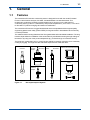


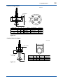

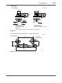
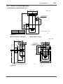
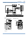


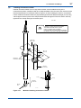
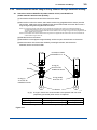
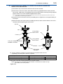


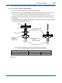
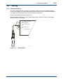


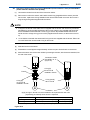
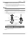

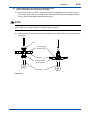
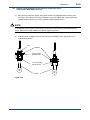
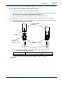

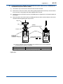

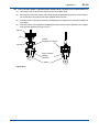

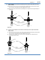


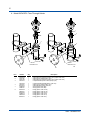
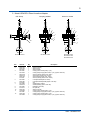


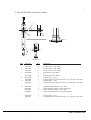

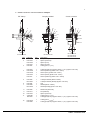


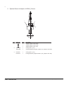


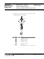
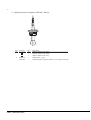
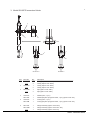

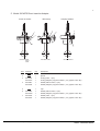


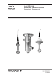
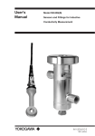

![ISC202SJ [スタイル:S1] 2線式電磁導電率伝送器](http://vs1.manualzilla.com/store/data/006585302_2-aa952b642369598fef037c616dd58a69-150x150.png)