1
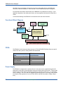
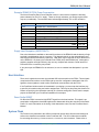
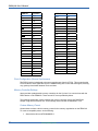
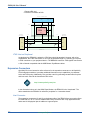
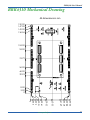
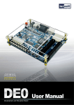
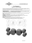
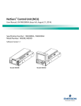
Opal Kelly
ZEM4310 User’s Manual
A compact (80mm x 60mm) integration board featuring the Altera Cyclone IV FPGA, SuperSpeed USB
3.0, on-board DDR2 memory, and two 16 MiB Flash
memories.
The ZEM4310 is a compact USB 3.0 (SuperSpeed) FPGA integration module featuring the Altera Cyclone IV FPGA, 1 Gib (64 Mx16-bit) DDR2 SDRAM, two 128 Mib SPI Flash devices, high-efficiency
switching power supplies, and two high-density 0.5-mm expansion connectors. The USB 3.0 SuperSpeed interface provides fast configuration downloads and PC-FPGA communication as well as easy access with our popular FrontPanel application and SDK. A low-jitter, 50 MHz crystal oscillator is attached
to the FPGA.
Software, documentation, samples, and related materials are
Copyright © 2014-2015 Opal Kelly Incorporated.
Opal Kelly Incorporated
Portland, Oregon
http://www.opalkelly.com
All rights reserved. Unauthorized duplication, in whole or part, of this document by any means except for brief
excerpts in published reviews is prohibited without the express written permission of Opal Kelly Incorporated.
Opal Kelly, the Opal Kelly Logo, and FrontPanel are trademarks of Opal Kelly Incorporated.
Linux is a registered trademark of Linus Torvalds. Microsoft and Windows are both registered trademarks of
Microsoft Corporation. All other trademarks referenced herein are the property of their respective owners and no
trademark rights to the same are claimed.
Revision History:
Date
Description
2014-03-03
Initial release.
2014-04-02
Added remarks about Pins reference.
2014-04-07
Added notes about LVDS termination resistors.
2014-12-09
Added reference to Pins column “HSMC+ok Jumper Silkscreen”.
2015-02-05
Added system clock pin notation.
2015-02-18
Added note about the host interface Reset signal.
2015-03-03
Added additional information about Pins.
Contents
Introducing the ZEM4310. . . . . . . . . . . . . . . . . . . . . . . . 5
PCB Footprint. . . . . . . . . . . . . . . . . . . . . . . . . . . . . . . . . . . . . 5
BRK4310 Breakout Board . . . . . . . . . . . . . . . . . . . . . . . . 5
Functional Block Diagram. . . . . . . . . . . . . . . . . . . . . . . . . . . . 6
FPGA . . . . . . . . . . . . . . . . . . . . . . . . . . . . . . . . . . . . . . . . . . . 6
Power Supply. . . . . . . . . . . . . . . . . . . . . . . . . . . . . . . . . . . . . 6
DC Power Connector. . . . . . . . . . . . . . . . . . . . . . . . . . . . 7
SuperSpeed USB 3.0 Interface . . . . . . . . . . . . . . . . . . . . . . . 7
On-board Peripherals. . . . . . . . . . . . . . . . . . . . . . . . . . . . . . . 7
Low-Jitter Crystal Oscillator. . . . . . . . . . . . . . . . . . . . . . . 7
128-MByte Word-Wide DDR2 Synchronous DRAM. . . . 7
FPGA Flash - 16 MiB Serial Flash Memory. . . . . . . . . . . 7
System Flash - 16 MiB Serial Flash Memory. . . . . . . . . . 7
LEDs. . . . . . . . . . . . . . . . . . . . . . . . . . . . . . . . . . . . . . . . . 7
HSMC-Style Expansion Connectors . . . . . . . . . . . . . . . . . . . 7
FrontPanel Support. . . . . . . . . . . . . . . . . . . . . . . . . . . . . . . . . 8
Programmer’s Interface. . . . . . . . . . . . . . . . . . . . . . . . . . 8
Applying the ZEM4310. . . . . . . . . . . . . . . . . . . . . . . . . . 9
Powering the ZEM4310. . . . . . . . . . . . . . . . . . . . . . . . . . . . . . 9
Power Distribution System. . . . . . . . . . . . . . . . . . . . . . . . 9
Power Budget. . . . . . . . . . . . . . . . . . . . . . . . . . . . . . . . . . 10
Example ZEM4310 FPGA Power Consumption. . . . . . . . 11
Supply Heat Dissipation (IMPORTANT!!). . . . . . . . . . . . . 11
Host Interface. . . . . . . . . . . . . . . . . . . . . . . . . . . . . . . . . . . . . 11
Reset Profile RESET. . . . . . . . . . . . . . . . . . . . . . . . . . . . 11
System Flash . . . . . . . . . . . . . . . . . . . . . . . . . . . . . . . . . . . . . 11
Layout. . . . . . . . . . . . . . . . . . . . . . . . . . . . . . . . . . . . . . . . 12
Loading a Power-On FPGA Configuration. . . . . . . . . . . . 12
FPGA Flash . . . . . . . . . . . . . . . . . . . . . . . . . . . . . . . . . . . . . . 12
System Clock . . . . . . . . . . . . . . . . . . . . . . . . . . . . . . . . . . . . . 12
LEDs. . . . . . . . . . . . . . . . . . . . . . . . . . . . . . . . . . . . . . . . . . . . 13
Power LED. . . . . . . . . . . . . . . . . . . . . . . . . . . . . . . . . . . . 13
HSMC Present LEDs. . . . . . . . . . . . . . . . . . . . . . . . . . . . 13
FPGA LEDs . . . . . . . . . . . . . . . . . . . . . . . . . . . . . . . . . . . 13
DDR2 SDRAM. . . . . . . . . . . . . . . . . . . . . . . . . . . . . . . . . . . . 13
Clock Configuration (Source Synchronous). . . . . . . . . . . 14
Memory Controller Settings. . . . . . . . . . . . . . . . . . . . . . . 14
JTAG. . . . . . . . . . . . . . . . . . . . . . . . . . . . . . . . . . . . . . . . . . . . 15
JTAG Signal Levels . . . . . . . . . . . . . . . . . . . . . . . . . . . . . 15
JTAG Host on Peripheral. . . . . . . . . . . . . . . . . . . . . . . . . 16
Expansion Connectors. . . . . . . . . . . . . . . . . . . . . . . . . . . . . . 16
Host Connector . . . . . . . . . . . . . . . . . . . . . . . . . . . . . . . . 16
Peripheral Connector. . . . . . . . . . . . . . . . . . . . . . . . . . . . 17
Mechanical Configurations. . . . . . . . . . . . . . . . . . . . . . . . . . . 17
Dual HSMC Configuration. . . . . . . . . . . . . . . . . . . . . . . . 17
Straddle Configuration. . . . . . . . . . . . . . . . . . . . . . . . . . . 18
ZEM4310 User’s Manual
Electrical Configurations. . . . . . . . . . . . . . . . . . . . . . . . . . . . . 18
HSMC+ok (Factory Default). . . . . . . . . . . . . . . . . . . . . . . 18
HSMC (Modifications Required). . . . . . . . . . . . . . . . . . . . 19
Setting I/O Voltages. . . . . . . . . . . . . . . . . . . . . . . . . . . . . 20
Considerations for Differential Signals. . . . . . . . . . . . . . . 21
BRK4310 Breakout Board. . . . . . . . . . . . . . . . . . . . . . . . . . . . 22
Peripheral Design Guide. . . . . . . . . . . . . . . . . . . . . . . . . . . . . 22
Physical Configuration : HSMC or Straddle Peripheral. . 23
Electrical Configuration : HSMC+ok or HSMC Peripheral.23
Input Power Supply . . . . . . . . . . . . . . . . . . . . . . . . . . . . . 23
I/O Configuration . . . . . . . . . . . . . . . . . . . . . . . . . . . . . . . 23
Clocking. . . . . . . . . . . . . . . . . . . . . . . . . . . . . . . . . . . . . . 24
JTAG. . . . . . . . . . . . . . . . . . . . . . . . . . . . . . . . . . . . . . . . . 24
Pins. . . . . . . . . . . . . . . . . . . . . . . . . . . . . . . . . . . . . . . . . . . . . 24
Toolbar. . . . . . . . . . . . . . . . . . . . . . . . . . . . . . . . . . . . . . . 24
Pin Lists . . . . . . . . . . . . . . . . . . . . . . . . . . . . . . . . . . . . . . 25
Filters. . . . . . . . . . . . . . . . . . . . . . . . . . . . . . . . . . . . . . . . 25
Search . . . . . . . . . . . . . . . . . . . . . . . . . . . . . . . . . . . . . . . 25
Export (PDF, CSV, Constraints Files). . . . . . . . . . . . . . . . 25
Peripherals. . . . . . . . . . . . . . . . . . . . . . . . . . . . . . . . . . . . 25
PCB Revisions . . . . . . . . . . . . . . . . . . . . . . . . . . . . . . . . . . . . 27
20121218 . . . . . . . . . . . . . . . . . . . . . . . . . . . . . . . . . . . . . 27
20131031 . . . . . . . . . . . . . . . . . . . . . . . . . . . . . . . . . . . . . 27
ZEM4310 Mechanical Drawing . . . . . . . . . . . . . . . . . . . 28
BRK4310 Mechanical Drawing . . . . . . . . . . . . . . . . . . . 29
4
www.opalkelly.com
ZEM4310 User’s Manual
Introducing the ZEM4310
The ZEM4310 is a compact FPGA board featuring the Altera Cyclone IV FPGA and SuperSpeed
USB 3.0 connectivity via a USB 3.0 Micro-B receptacle. Designed as a full-featured integration
system, the ZEM4310 provides access to over 160 I/O pins on its 484-pin Cyclone IV device and
has a 128-MiByte DDR2 SDRAM available to the FPGA. Two SPI Flash devices provide a total
of 32 MiB of non-volatile memory, one attached to the USB microcontroller and one attached
to the FPGA. The ZEM4310 is designed for medium-sized FPGA designs with a wide variety of
external interface requirements.
PCB Footprint
A mechanical drawing of the ZEM4310 is shown at the end of this manual. The PCB is 80mm
x 60mm with four mounting holes (M2 metric screws) spaced as shown in the figure. These
mounting holes are electrically isolated from all signals on the ZEM4310. The two connectors
(USB and DC power) overhang the PCB by approximately 1mm in order to accommodate mounting within an enclosure.
The ZEM4310 has two high-density 180-pin connectors on the bottom side which provide access
to many FPGA pins, power, and JTAG.
BRK4310 Breakout Board
A simple breakout board (the BRK4310) is provided as an optional accessory to the ZEM4310.
This breakout board provides DC power, JTAG connector, and easy access to the high-density
connectors on the ZEM4310 by routing them to lower-density 2mm-spaced thru-holes. The
breakout board also provides a convenient reference for building boards that will mate to the
ZEM4310.
www.opalkelly.com
5
ZEM4310 User’s Manual
Opal Kelly reserves the right to change the form-factor and possibly pinout of the BRK4310.
Therefore, unlike the ZEM4310, it is not intended or recommended for production integration.
Full schematics and Gerber artwork files for the BRK4310 are provided free of charge. If your
application depends on the existing form factor, you may reproduce this board from these documents.
A mechanical drawing of the BRK4310 is also shown at the end of this document.
Functional Block Diagram
System Flash
16 MiB
USB 3.0
DDR2 SDRAM
128 MiB
FPGA Flash
16 MiB
Host
Interface
Bus
USB Micro
50 MHz
Clock
Altera Cyclone IV
EP4CE55F23C8N
1.8v
CMOS
2 LEDs
80+ I/O
80+ I/O
HSMC Samtec Expansion Connector
HSMC Samtec Expansion Connector
FPGA
The ZEM4310 is built around an Altera Cyclone IV FPGA (EP4CE55F23C8N). Resource specifications from the Cyclone IV Family Manual are listed below.
Feature
ZEM4310
FPGA
EP4CE55F23C8N
Logic Elements (4-LUT + DFF)
55,856
Embedded Memory
2,340 Kib
18x18 Multipliers
154
Global Clock Networks
20
General-Purpose PLLs
4
Power Supply
The ZEM4310 is designed to be operated from a 5-volt power source supplied through the DC
power jack on the device or the expansion connectors on the bottom of the device. This provides
power for the four high-efficiency switching regulators on-board to provide 3.3v, 1.2v, and expansion I/O voltages. 2.5v, 1.8v, and 0.9v supplies are derived from the 3.3-volt supply using a small
low-dropout (LDO) regulators for use as FPGA, DDR2, and DDR2 termination voltage, respectively.
6
www.opalkelly.com
ZEM4310 User’s Manual
DC Power Connector
The DC power connector on the ZEM4310 is part number PJ-102AH from CUI, Inc. It is a standard “cannon-style” 2.1mm / 5.5mm jack. The outer ring is connected to DGND. The center pin
is connected to +VDC.
SuperSpeed USB 3.0 Interface
The ZEM4310 uses a Cypress FX3 USB microcontroller to make the device a USB 3.0 peripheral. As a USB peripheral, the device is instantly recognized as a plug and play peripheral on
millions of PCs. More importantly, FPGA downloads to the device happen quickly, virtual instruments under FrontPanel update quickly, and data transfers are blazingly fast.
On-board Peripherals
The ZEM4310 is designed to compactly support a large number of applications with a small number of on-board peripherals. These peripherals are listed below.
Low-Jitter Crystal Oscillator
A fixed-frequency, 50 MHz, low-jitter oscillator is included on-board and outputs a 1.8-v CMOS
signal to the FPGA. The Cyclone IV FPGA can produce a wide range of clock frequencies using
the on-chip capabilities.
128-MByte Word-Wide DDR2 Synchronous DRAM
The device also includes a 128-MiByte DDR2 SDRAM (Micron MT47H64M16HR-3:H or compatible) with a full 16-bit word-wide interface to the FPGA. This SDRAM is attached exclusively to
the FPGA and does not share any pins with the expansion connector. The maximum clock rate
of the SDRAM is 333 MHz for a maximum peak memory bandwidth of over 10 Gb/s.
Note: The Altera Cyclone IV soft memory controllers for the -8 speed grade is limited to a single
32-bit port operating at 133 MHz for a peak memory bandwidth of 4.25 Gb/s.
FPGA Flash - 16 MiB Serial Flash Memory
A 128 Mib serial flash device (Numonyx N25Q128A11B1240E or equivalent) provides on-board
non-volatile storage for the FPGA. This device is attached directly to the FPGA for use in your
design.
System Flash - 16 MiB Serial Flash Memory
A 128 Mib serial flash device (Numonyx N25Q128A11B1240E or equivalent) provides on-board
non-volatile storage accessible to the USB microcontroller. This device is used to store device
firmware and configuration settings as well as other user assets such as FPGA configuration files
or calibration data. Erase, read, and write functions are available at all times (with or without a
configured FPGA) through the use of FrontPanel API methods.
LEDs
Two LEDs and are available for general use as indicators.
HSMC-Style Expansion Connectors
Two high-density HSMC (High-Speed Mezzanine Card), 180-pin expansion connectors are available on the bottom-side of the ZEM4310 PCB. These expansion connectors provide user access
www.opalkelly.com
7
ZEM4310 User’s Manual
to several power rails on the ZEM4310, the JTAG interface on the FPGA, and 124 exclusive I/O
pins on the FPGA, including several GCLK inputs. In the default configuration, these connectors
provide a pinout which is an extended version of HSMC (HSMC+ok). The ZEM4310 may optionally be configured for straight HSMC with the removal of some jumper resistors.
The connectors on the ZEM4310 are Samtec part number: QSH-090-01-L-D-A. The table below
lists the appropriate Samtec mating connectors along with the total mated height.
Samtec Part Number
Mated Height
QTH-090-01-F-D-A
5.00mm (0.197”)
QTH-090-02-F-D-A
8.00mm (0.315”)
QTH-090-03-F-D-A
11.00mm (0.433”)
QTH-090-04-F-D-A
16.10mm (0.634”)
QTH-090-05-F-D-A
19.10mm (0.752”)
FrontPanel Support
The ZEM4310 is fully supported by Opal Kelly’s FrontPanel Application. FrontPanel augments
the limited peripheral support with a host of PC-based virtual instruments such as LEDs, hex
displays, pushbuttons, toggle buttons, and so on. Essentially, this makes your PC a reconfigurable I/O board and adds tremendous value to the ZEM4310 as an experimentation or prototyping system.
Programmer’s Interface
In addition to complete support within FrontPanel, the ZEM4310 is also fully supported by the
FrontPanel SDK, a powerful C++ class library available to Windows, Mac OS X, and Linux programmers allowing you to easily interface your own software to the device.
In addition to the C++ library, wrappers have been written for C#, Java, and Python making the
API available under those languages as well. Sample wrappers (unsupported) are also provided
for Matlab and LabVIEW.
Complete documentation and several sample programs are installed with FrontPanel.
8
www.opalkelly.com
ZEM4310 User’s Manual
Applying the ZEM4310
Powering the ZEM4310
The ZEM4310 requires that this supply be clean, filtered, and within the range of 4.5v to 5.5v.
This supply must be delivered through the +VDC pins on the device’s DC power connector or
(optionally) the two expansion connectors.
Power Distribution System
The module’s power distribution system is summarized in the following diagram. User-available
supplies are listed along the right side of the diagram. “HSMC+ok” signals are available to peripherals in the default factory configuration of the ZEM4310. These signals are an extension of
the standard HSMC specification and are not available to typical HSMC peripherals. Please see
later sections of this document for more details on expansion connector configurations.
www.opalkelly.com
9
ZEM4310 User’s Manual
Linear Supply
Switching Supply
Jumper
+VDC
(+4.5 to +5.5v)
HSMC+ok VDC
3.3v
HSMC 3.3V
6A
System Controller
FPGA Vccio
0.9v
500mA
DDR2 Termination
1.5A
HSMC+ok +1.8v
250mA
HSMC+ok +2.5v
1.8v
DDR2
2.5v
FPGA Vcca
1.2v
HSMC+ok +1.2v
3A
System Controller
FPGA Vccint
ADJv
1A
HSMC VCCIO
ADJv
1A
HSMC VCCIO
Power Budget
The table below can help you determine your power budget for each supply rail on the ZEM4310.
All values are highly dependent on the application, speed, usage, and so on. Entries we have
made are based on typical values presented in component datasheets or approximations based
on Altera power estimator results. Shaded boxes represent unconnected rails to a particular
component. Empty boxes represent data that the user must provide based on power estimates.
The user may also need to adjust parameters we have already estimated (such as FPGA Vccio
values) where appropriate.
Component(s)
1.2v
1.8v
System
335 mW
45 mW
50 mW
630 mW
700 mW
DDR2
2.5v
3.3v
FPGA Vccint
FPGA Vccaux
88 mW
100 mW
FPGA Vcco (DDR2), est.
42 mW
50 mW
FPGA Vcco (System), est.
100 mW
115 mW
FPGA Vcco (User)
Total:
Available: 3,600 mW
10
1,500 mW
www.opalkelly.com
1,250 mW
19,800 mW
ZEM4310 User’s Manual
Example ZEM4310 FPGA Power Consumption
The Altera PowerPlay Early Power Estimator version 11 was used to compute the following
power estimates for the Vccint supply. These are simply estimates; your design requirements
may vary considerably. The numbers below indicate approximately 70% to 80% utilization.
Component
Parameters
Vccint
Clock
200 MHz CLK - 40,000 fanout
370 mW
Clock
100 MHz GCLK - 40,000 fanout
185 mW
Logic
200 MHz, 30,000 LUTs, 30,000 DFFs
613 mW
Logic
100 MHz, 15,000 LUTs, 15,000 DFFs
153 mW
RAM
16-bit, 100 @ 200 MHz, 100 @ 100 MHz
192 mW
DSP
125 @ 200 MHz
131 mW
Misc.
DCM, PLL, etc.
17 mW
Total: 1,661 mW
Available: 3,600 mW
Supply Heat Dissipation (IMPORTANT!!)
Due to the limited area available on the small form-factor of the ZEM4310 and the density of logic
provided, heat dissipation may be a concern. This depends entirely on the end application and
cannot be predicted in advance by Opal Kelly. Heat sinks may be required on any of the devices
on the ZEM4310. Of primary focus should be the FPGA (U15) and SDRAM (U8). Although the
switching supplies are high-efficiency, they are very compact and consume a small amount of
PCB area for the current they can provide.
If you plan to put the ZEM4310 in an enclosure, be sure to consider heat dissipation in your design.
Host Interface
There are 41 signals that connect the on-board USB microcontroller to the FPGA. These signals
comprise the host interface on the FPGA and are used for configuration downloads. After configuration, these signals are used to allow FrontPanel communication with the FPGA.
If the FrontPanel okHost module is instantiated in your design, you must map the interface pins
to specific pin locations using set location assignments. This may be done using the Quartus Pin
Planner or specifying the constraints manually in a Quartus settings file. Please see the sample
projects included with your FrontPanel installation for examples.
Reset Profile RESET
Pin B2 of the FPGA is an active-high RESET signal from the host interface. This signal is asserted when configuration download begins and is deasserted during the execution of the Reset
Profile. For more information on the timing of this deassertion event, see the FrontPanel User’s
Manual.
System Flash
The Flash memory attached to the USB microcontroller stores device firmware and settings as
well as user data that is accessible via the FrontPanel API. The API includes three methods
for accessing this memory: FlashEraseSector, FlashWrite, and FlashRead. Please refer to
www.opalkelly.com
11
ZEM4310 User’s Manual
the FrontPanel User’s Manual and the FrontPanel API Reference for information about applying
these methods.
Layout
The Numonyx N25Q128A11B1240E is a 16 MiB Flash memory arranged into 256 64-kiB sectors.
Each sector contains 256 256-byte pages. Sectors 0...15 are reserved for device firmware and
settings and are not accessible to user software. The remaining 15 MiB may be erased, written,
and read using the FrontPanel API at any time even without a valid FPGA configuration. Full 64
kiB sectors must be erased at a time. However, contents may be read or written on any page
address boundary.
Loading a Power-On FPGA Configuration
The user-area in System Flash may be used to store an Altera bitfile to configure the FPGA at
power-on. Power-on configuration takes approximately 6-10 seconds from when power is applied. A full Reset Profile may also be performed after configuration.
The API is used to erase and program the power-on bitfile and the Flashloader sample is provided to perform these steps from a simple command-line utility. Source code to the Flashloader
sample is included with the FrontPanel SDK.
Called with a single argument (the filename for a valid Altera bitfile), the Flashloader sample will
erase the first sectors in the System Flash user-area, then write the bitfile. It will also setup the
Boot Reset Profile to point to this area on power-on.
No Power-On Configuration
Called with no arguments, the Flashloader sample will clear the existing Boot Reset Profile. This
has the effect of preventing an FPGA configuration from being loaded at power-on. This functionality may also be accomplished from the API by setting an empty okTFPGAResetProfile using
the API SetFPGAResetProfile. See the FrontPanel API Reference for details.
FPGA Flash
The SPI Flash attached to the FPGA is a Numonyx N25Q128A11B1240E or equivalent. It provides non-volatile storage for use by the FPGA. It may not be used for FPGA configuration storage. The System Fash is used to store FPGA “boot” configurations.
The Flash / FPGA pin mappings are shown in the table below.
Flash Pin
FPGA Pin
C
G3
S
J4
DQ0
G4
DQ1
K7
DQ2 / W
J2
DQ3 / HOLD
J1
System Clock
The host interface provides a 100.8 MHz clock that may be applied to your design. Additionally, a
50 MHz CMOS oscillator provides a clock source.
12
www.opalkelly.com
ZEM4310 User’s Manual
System Clock
FPGA Pin
50 MHz
A12
LEDs
Power LED
The power LED is attached directly to the 3.3v power supply and indicates when that supply is
on.
HSMC Present LEDs
One LED per HSMC connector is attached to the PRSNTn pin on the HSMC connector. The
HSMC peripheral typically connects this pin to DGND to indicate presence. Therefore, these
LEDs will indicate when the corresponding HSMC peripheral is attached.
FPGA LEDs
Two LEDs are attached to the FPGA on Bank 1. These LEDs will indicate when the corresponding FPGA pin is set to logic ‘0’. Note that the LED anodes are connected to +3.3VDD. To turn
OFF an LED, it should be set to high-impedance. The LEDs are mapped to FPGA as shown in
the following table.
LED
FPGA Pin
D4
G5
D5
H5
DDR2 SDRAM
The Micron DDR2 SDRAM is connected exclusively to the 1.8-v I/O on Bank 7 and Bank 8 of the
FPGA. The tables below list these connections.
www.opalkelly.com
13
ZEM4310 User’s Manual
DDR2 Pin
FPGA Pin
CK
B10
CK
A10
CKE
F16
CS
C18
RAS
B17
CAS
G15
WE
G16
LDQS
B13
LDQS
NC
UDQS
F13
UDQS
NC
LDM
E14
UDM
C19
ODT
B18
A0
G13
A1
E12
A2
C13
A3
G10
A4
D8
A5
E8
A6
G11
A7
G9
A8
G8
A9
D10
DDR2 Pin
FPGA Pin
A10
E11
A11
E10
A12
F9
A13
E5
BA0
G14
BA1
D18
BA2
F14
D0
A15
D1
B14
D2
D13
D3
A13
D4
F11
D5
A14
D6
B15
D7
B16
D8
C17
D9
A17
D10
A16
D11
F15
D12
E15
D13
E16
D14
A18
D15
D19
Clock Configuration (Source Synchronous)
The DDR2 clocking is designed to be source-synchronous from the FPGA. This means that the
FPGA sends the clock signal directly to the SDRAM along with control and data signals, allowing
very good synchronization between clock and data.
Memory Controller Settings
Altera provides synthesizeable memory controllers for the Cyclone IV to communicate with the
DDR2 device on the ZEM4310. These are soft-IP cores provided by Altera.
The following settings are used to generate the memory interface core for our RAMTester
sample using Altera’s Quartus tool. These settings were used with ALTMEMPHY v12.0.
Custom Memory Preset
Quartus does not have a built-in memory preset for the memory organization on the ZEM4310.
To create a compatible preset, do the following:
1. Start with the Micron MT47H64M8CB-3
14
www.opalkelly.com
ZEM4310 User’s Manual
2. Modify the following parameters:
Total memory interface DQ width: 16
Row address width: 13
Bank address width: 3
RAS to RAS delay time (tRRD): 8.2 ns
Read to precharge time (tRTP): 8.2 ns
3. Save the preset as Custom (Micron MT47H64M16-3)
General Settings
Device Family
Cyclone IV E
Speed Grade8
PLL Reference Clock Freq.
50 MHz
Memory Clock Freq.
133 MHz
Local Interface Clock Freq.
133 MHz
Local Interface Width
32 bits
Controller Data Rate
Full
Memory Preset
Custom (Micron MT47H64M16-3)
PHY Settings
Clock Phase90
Auto-Calibration Simulation
Quick Calibration
Controller Settings
Controller Architecture
Low Power Mode
Efficiency
Starvation Limit Per Command
Local-to-Memory Address Mapping
Command Queue Look-Ahead Depth
Local Maximum Burst Count
Advanced Features
High Performance Controller II
Nothing Selected
Enable Reordering Selected
10 commands
CHIP-ROW-BANK-COL
4
4
None Selection
JTAG
The JTAG connections on the FPGA are wired directly to the 2mm connector JP3 on the module to facilitate FPGA configuration and Signal Tap usage using a Terasic USB Blaster or Altera
ByteBlaster JTAG cable. The JTAG chain on the ZEM4310 is illustrated in the diagram below.
Note that a JTAG chain must form a complete loop from TDI to TDO. If either of the HSMC
modules is not connected to the ZEM4310, the loop will be incomplete. You may bypass the
expansion connectors using switches SW1 or SW2 as necessary. Silkscreen indications on the
ZEM4310 indicate the proper switch position for bypass.
JTAG Signal Levels
Level translation is used to convert the 1.8v signal levels of the FPGA’s JTAG interface to 2.5v
signal levels at the HSMC expansion connectors J1 and J2.
The 2.5v JTAG signal level is set by a 0-Ω resistor at R8 which is inserted at the factory. To utilize
a 3.3v JTAG signal level, you must:
www.opalkelly.com
15
ZEM4310 User’s Manual
1. Remove R8; and
2. Install a 0-Ω resistor at R93.
Altera JTAG Cable
TDO
TDI
TCK TMS
JP3
TDI
FPGA
TMS
TCK
TDO
HSMC
Module
J2
↑ 1.8v
HSMC
Module
J1
2.5v ↓
TMS
TCK
52
52
51
51
TMS
TCK
TDO
55
56
TDI
SW2
TDI
SW1
56
55
TDO
ZEM4310
JTAG Host on Peripheral
As designed, the ZEM4310 is where the JTAG host should be attached. However, with a few
modifications, the JTAG connections on JP3 may be passed through to J1 allowing you to place
a JTAG connector on your peripheral device. The BRK4310 has these JTAG signals connected to
a 100-mil header compatible with the USB Blaster / ByteBlaster cables.
Expansion Connectors
Opal Kelly Pins is an interactive online reference for the expansion connectors on all Opal Kelly
FPGA integration modules. It provides additional information on pin capabilities, pin characteristics, and PCB routing. Additionally, Pins provides a tool for generating constraint files for place
and route tools. Pins can be found at the URL below.
http://www.opalkelly.com/pins
In the discussion below, as in the HSMC Specification, the ZEM4310 is the “host board.” The
device attached to the ZEM4310 is called the “peripheral” or “mezzanine board.”
Host Connector
The expansion connectors (J1 and J2) on the bottom side of the ZEM4310 are part number Samtec QSH-090-01-L-D-A. This is a standard QSH family connector with 3 fully-populated banks
and a total of 180 physical pins in addition to a ground spine.
16
www.opalkelly.com
ZEM4310 User’s Manual
The Altera HSMC Specification provides for an application-specific version of this connector, the
Samtec ASP-122953-01, to be used on host boards. This connector is fully-populated on banks 2
and 3, but bank 1 is configured such that every third pin on each side is de-populated.
Note: The pin numbering in the HSMC Specification is based only on populated pins. Since the
ZEM4310 is equipped with the fully-populated QSH connector, there are more pins and the pin
numbering is different than the HSMC Specification. Please refer to the ZEM4310 Pins Refence
guide for detailed pin lists.
Peripheral Connector
Peripherals can be designed with either the standard Samtec QTH-090-01-L-D-A or the application-specific (HSMC) ASP-122952-01. The standard connector is the fully-populated mating
connector and the application-specific connector is de-populated in bank 1 at every third pin. The
standard connector is typically somewhat less expensive. HSMC+ok pins are only available on
the fully populated connector.
Mechanical Configurations
There are two Samtec QSH-090-01-L-D-A expansion connectors on the bottom of the module.
These connectors are oriented to accommodate two different peripheral attachment styles to the
module, depending on the application.
Dual HSMC Configuration
In the Dual HSMC Configuration, the ZEM4310 may be connected to two standard HSMC peripherals. Shown below, the module is connected to two independent EVB1007 peripherals, each
a standalone HSMC peripheral. Please see the notes in the Electrical Configurations section
regarding HSMC for special considerations when using independent HSMC peripherals with the
EVB1007.
www.opalkelly.com
17
ZEM4310 User’s Manual
Straddle Configuration
In the Straddle Configuration, the ZEM4310 is connected to a single peripheral module designed
to mate to both expansion connectors. This is similar to how many other Opal Kelly modules are
configured.
Electrical Configurations
This section describes the electrical characteristics of the expansion connectors and how the
ZEM4310 connects electrically to peripherals. Both mechanical configurations work with both
electrical configurations.
HSMC+ok (Factory Default)
The ZEM4310 is configured at the factory with additional signals pinned out to the QSH headers.
These signals are connected to pins that are depopulated on the HSMC-specified “ASP” connector.
The table below lists the additional signals available in the HSMC+ok configuration. Please visit
the ZEM4310 page on Opal Kelly Pins for detailed pinout information.
Signal(s)
Description
+VDC
DC input to the device. This must be within the range +4.5v to +5.5v.
VCCIO2, VCCIO3,
VCCIO4, VCCIO5,
VCCIO6
FPGA bank voltages for supporting I/O standards at the bank level rather than the
coarser connector level that HSMC specifies.
VREF_BANK2,
VREF_BANK3,
VREF_BANK4,
VREF_BANK5,
VREF_BANK6
FPGA bank Vref voltages for supporting voltage-referenced I/O standards such as
SSTL and HSTL.
+1.2VDD
+1.2 volt output from the module’s switching regulator.
+1.8VDD
+1.8 volt output from the module’s linear regulator.
+2.5VDD
+2.5 volt output from the module’s linear regulator.
+J1_HSMC_VCCIO
DC output from the module’s HSMC switching regulator for J1.
18
www.opalkelly.com
ZEM4310 User’s Manual
Signal(s)
Description
J1_HSMC_VS0,
J1_HSMC_VS1,
J1_HSMC_VS2
Inputs to set the HSMC switching regulator output voltage for J1. When used, these
must be tied to either +VDC or DGND. The corresponding set resistors on the
ZEM4310 must also be removed.
+J2_HSMC_VCCIO
DC output from the module’s HSMC switching regulator for J2.
J2_HSMC_VS0,
J2_HSMC_VS1,
J2_HSMC_VS2
Inputs to set the HSMC switching regulator output voltage for J2. When used, these
must be tied to either +VDC or DGND. The corresponding set resistors on the
ZEM4310 must also be removed.
JTAG_TCK,
JTAG_TMS,
JTAG_TDI,
JTAG_TDO
JTAG host port signals if the peripheral is to provide a JTAG host port. Note that
these are not the same as the HSMC signals for JTAG chain.
PLL1_CLKOUT_P/N
PLL4_CLKOUT_P/N
FPGA PLL output differential pairs.
BANK1_CLK,
BANK8_CLK
Additional FPGA clock inputs (banks 1 and 8, respectively) for low-skew delivery of
an external clock to the FPGA.
OVP_FLAG
Reserved
CHARGE_DETECT
Reserved
HSMC (Modifications Required)
Note: This section describes optional modifications to the ZEM4310. Making these modifications
voids the manufacturer warranty. For OEM applications, Opal Kelly can make these modifications
prior to shipment (at no additional charge) in volumes of 100 or more.
With the removal of some jumper resistors, a factory ZEM4310 may be configured as a standard
HSMC host except that standard Samtec QSH headers are installed instead of the ASP connector suggested by the HSMC specification.
The highlighted areas in the photo below indicate the locations of the jumper banks that contain
resistors that must be removed to achieve HSMC pinout. Some locations are also used to set
the connector power supply voltage. See the section below, titled “Setting I/O Voltages” for more
detail.
To see which specific HSMC+ok signals are associated with the silkscreen markings on the PCB,
enable the column “HSMC+ok Jumper Silkscreen” in Pins.
www.opalkelly.com
19
ZEM4310 User’s Manual
Setting I/O Voltages
FPGA I/O banks 2, 3, 4, 5, and 6 are connected to the two expansion connectors. Each of these
banks has an independent I/O voltage that is used to determine the available I/O standards to
support on that bank. Control over these bank voltages depends on whether you’re using the
standard HSMC configuration or HSMC+ok.
Two switching regulators control the I/O voltages for the banks wired to the expansion connectors, one for each expansion connector. The outputs of these regulators are connected through
ferrite beads to the bank VCCIO pins on the FPGA according to the table below:
Connector
Supply
I/O Bank
Ferrite Bead
JP1
2
FB5
3
FB6
5
FB8
4
FB7
6
FB9
JP2
HSMC+ok Configuration
The HSMC+ok configuration extends the standard HSMC capabilities in two ways:
1. +VCCIO is available from the output of the connector’s I/O supply to pin 18.
2. The VS2, VS1, and VS0 inputs that determine the I/O supply voltage are available on
pins 36, 30, and 24, respectively.
To set the I/O supply voltage from an expansion peripheral, the following preparations must be
made:
20
www.opalkelly.com
ZEM4310 User’s Manual
1. Appropriate jumpers for HSMC+ok mode must be installed.
2. VS2, VS1, and VS0 pins must be pulled to either +VDC(1) or DGND(0) according to the
table below.
Voltage
VS2
VS1
VS0
3.3
0
0
0
2.5
0
0
1
1.8
0
1
0
1.5
0
1
1
1.25
1
0
0
1.2
1
0
1
0.8
1
1
0
HSMC Configuration
In the HSMC configuration, each connector’s supply voltage is controlled by a set of six jumper
(4.7 kΩ) resistors. As shipped from the factory, the settings specify a 2.5v I/O voltage for both
banks. To change this setting, install the jumper resistors in specified in dark text. Remove the
resistors in light text.
Voltage
J1 Set Resistors
J2 Set Resistors
3.3
R11, R10, R14
R19, R18, R16
R13, R12, R15
R21, R20, R17
2.5
Factory Setting
R11, R10, R14
R19, R18, R16
R13, R12, R15
R21, R20, R17
1.8
R11, R10, R14
R19, R18, R16
R13, R12, R15
R21, R20, R17
1.5
R11, R10, R14
R19, R18, R16
R13, R12, R15
R21, R20, R17
1.25
R11, R10, R14
R19, R18, R16
R13, R12, R15
R21, R20, R17
1.2
R11, R10, R14
R19, R18, R16
R13, R12, R15
R21, R20, R17
0.8
R11, R10, R14
R19, R18, R16
R13, R12, R15
R21, R20, R17
Note: Both JP1 and JP2 route signals to Bank 5 on the FPGA but Bank 5 receives its power (VCCIO5) from the connector supply for JP1. Therefore, care must be taken to choose voltage standards for signals that connect to Bank 5 that are compatible with the connector supply for JP1.
Considerations for Differential Signals
The ZEM4310 PCB layout and routing has been designed with several applications in mind,
including applications requiring the use of differential (LVDS) pairs. Please refer to the Altera Cyclone IV documentation for details on using differential I/O standards with the Cyclone IV FPGA.
Note: LVDS output on the Cyclone IV is restricted to banks 1, 2, 5, and 6. LVDS input is available
on all banks. For more information, please refer to the Cyclone IV Device Handbook, Volume 1
from Altera.
www.opalkelly.com
21
ZEM4310 User’s Manual
Characteristic Impedance
The characteristic impedance of all routes from the FPGA to the expansion connector is approximately 50 Ω.
Differential Terminations
The ZEM4310 is factory configured for single ended signal standards. The ZEM4310 Pins Reference includes a column titled “LVDS Term RefDes” that indicates the corresponding PCB reference designator for each LVDX receiver pair. For ideal termination of LVDS receivers, the user
may install a surface-mount (0402) 100-Ω termination resistor at the corresponding site on the
ZEM4310 PCB. The locations of these sites are labeled in silkscreen on the bottom of the PCB.
Alternatively, termination resistors may be installed on the peripheral module.
Differential Pair Lengths
In many cases, it is desirable that the route lengths of a differential pair be matched within some
specification. Care has been taken to route differential pairs on the FPGA to adjacent pins on
the expansion connectors whenever possible. We have also included the lengths of the board
routes for these connections to help you equalize lengths in your final application. Due to space
constraints, some pairs are better matched than others.
Reference Voltage Pins (Vref)
Altera Cyclone IV devices have additional support for voltage-referenced I/O standards such as
SSTL and HSTL. Usage of these standards requires an input reference voltage and termination
voltage. More information is available in the Cyclone IV Device Handbook, Volume 1, Chapter 6:
I/O Features in Cyclone IV Devices. The bank Vref pins are only made available with the additional HSMC+ok electrical signals.
BRK4310 Breakout Board
The BRK4310 is a simple two-layer “breakout board” which can be used to evaluate or transition
to the ZEM4310. It provides standard 2-mm thru-hole connections to the 0.5-mm high-density
connectors on the ZEM4310 and a DC power connector (2.1mm/5.5mm, center positive) for providing +VDC to the ZEM4310.
Full schematics and PCB design files are available at the following web address:
http://www.opalkelly.com/download
The pinout reference for the BRK4310 is included in the ZEM4310 Pins Reference available
online:
http://www.opalkelly.com/pins
Peripheral Design Guide
This section is intended to provide a series of questions, considerations, and guidelines to follow
as you design a peripheral to mate to the ZEM4310. Upon reviewing the items in this section,
refer to the other portions of this documentation for more detail.
22
www.opalkelly.com
ZEM4310 User’s Manual
Physical Configuration : HSMC or Straddle Peripheral
If you’re building a standard HSMC peripheral, you are restricted to a single HSMC connector.
If you plan to only use the peripheral with the ZEM4310, you can build a form factor that utilizes
both connectors and, of course, the additional FPGA signals provided by two full HSMC connectors.
Electrical Configuration : HSMC+ok or HSMC Peripheral
Regardless of your device’s physical configuration you have the option of choosing a standard
HSMC pinout or using the additional pins provided by the HSMC+ok pinout. HSMC is more compatible with other host hardware. HSMC+ok provides additional functionality on pins that are otherwise depopulated in the HSMC standard. HSMC+ok is compatible with some standard HSMC
peripherals (depending on if and how they connect the depopulated HSMC connector pins) and
is compatible with how the ZEM4310 ships in the default configuration.
HSMC provides standard compatibility but requires modifications to the device. However, Opal
Kelly can perform these modifications (for no additional cost) for volume purchases of 100 pieces
or more.
Input Power Supply
Typically, you will provide +VDC (+4.5 to +5.5 volts) through the barrel connector on the
ZEM4310. With the addition of one or more (for added current) jumper resistors, you may optionally deliver +VDC through the expansion connector J2.
I/O Configuration
I/O configuration involves setting the power supply reference depending on the signal standards
you need to utilize based on the hardware that will communicate with the FPGA.
Reference Power (HSMC+ok)
HSMC+ok offers a few enhancements for I/O power.
•
•
•
•
Additional pins allow the peripheral to provide specific bank voltages.
VREF pins allow the peripheral to set bank reference voltages which are useful for some
signal standards.
VS2, VS1, and VS0 signals which control the programmable I/O power supplies are provided to allow the peripheral to set the I/O voltage.
The I/O power supply output is available on the connector.
Reference Power (HSMC)
HSMC provides for a single voltage setting for the entire connector and the ZEM4310 has one
programmable power supply for each connector. By default, each supply is configured for 2.5v
but with some resistor changes on the ZEM4310, you can change this to one of several voltages.
HSMC does not provide a pin from the host to the peripheral that contains the I/O power supply
voltage. Nor does HSMC provide pins to provide VREF (required for some signal standards) to
the FPGA.
I/O Standards and Pin Selections
Opal Kelly’s Pins is the definitive reference for pin selection:
www.opalkelly.com
23
ZEM4310 User’s Manual
http://pins.opalkelly.com
Considerations here are which I/O supply to use for the FPGA I/O banks and whether or not differential I/O is required.
Clocking
The ZEM4310 has an on-board 50 MHz oscillator as well as the 100.8 MHz clock from the host
interface.
In the HSMC electrical configuration, CLKIN0 on the expansion connectors are routed to dedicated clock inputs on the FPGA and can be used for providing a clock from your peripheral.
CLKIN1p/n and CLKIN2p/n also route to the dedicated clock inputs with modifications to the
default jumpers.
Additinoally, in the HSMC+ok electrical configuration, BANK1_CLK and BANK8_CLK are routed
to dedicated clock inputs via user-installed jumpers. Cyclone IV PLL outputs PLL1_CLKOUTp/n
and PLL4_CLKOUTp/n are also made available via jumpers. These PLL outputs may optionally
be used as I/O.
JTAG
If JTAG is an important consideration for your application, note that the HSMC specification places the JTAG host on the ZEM4310 so the JTAG host controller would connect to the ZEM4310
in the default configuration. HSMC+ok provides access to these JTAG host connections on the
peripheral device. See the JTAG section of this document for more information.
Pins
Opal Kelly Pins is an interactive online reference for the expansion connectors on all Opal Kelly
FPGA integration modules. It provides additional information on pin capabilities, pin characteristics, and PCB routing. Additionally, Pins provides a tool for generating constraint files for place
and route tools. Pins can be found at the URL below.
http://www.opalkelly.com/pins
Toolbar
The toolbar at the top of a Pins product page has a number of features. Explore a bit; you won’t
break it.
24
www.opalkelly.com
ZEM4310 User’s Manual
Pin Lists
As the primary reference for Opal Kelly integration module expansion connectors, Pin Lists contain a comprehensive table of the FPGA-to-Connector data including connector pin, FPGA pin,
signal description, routed length (when applicable), breakout board pin mapping, FPGA I/O bank,
and other properties.
By default, not all data columns are visible. Click on the “Toggle Filters” icon at the top-left to select which columns to show. Depending on the specific module, several additional columns may
be shown. The data in these columns is always exported when you export the pin list to CSV.
Filters
You can hide or show the additional information associated with each signal by clicking on the
icon at the top left (“Toggle Filters”). Use these filters to limit the visible pin listing to particular
subsets of signals you are interested in.
Search
You can search the pin list using the search entry at the top-right. Click on the magnifying glass
drop-down to adjust the function of the search to one of:
•
•
•
Highlight - Highlights search results only.
Hide Matching - Hides rows where search matches are found.
Show Only Matching - Shows only rows where a search match is found.
Export (PDF, CSV, Constraints Files)
The export button near the search entry allows you to export the pin list in several formats. PDFs
can be viewed or printed. CSV can be loaded into a spreadsheet application or manipulated with
scripts. Constraints files can be used as inputs to Xilinx and Altera synthesis and mapping tools.
The constraints files include additional mapping information for other peripherals on the module
such as memory, clock oscillators, and LEDs.
Peripherals
A Pins Peripheral is a project definition where you can enter your top-level HDL design nets to
have Pins generate a complete constraint file for you.
www.opalkelly.com
25
ZEM4310 User’s Manual
When you create a Peripheral, you will select a target integration module. The Peripheral is
paired to this module so that the design parameters match the features and expansion capabilities of the module.
Specifying Net Names
The Pin List view for a Peripheral includes three additional, editable columns:
•
•
•
Design Net - The name of the signal as it appears in your top-level HDL.
Constraints - Text that is inserted into the constraints file for that signal.
Comment - Additional comment text that is added to the constraints file.
These additional data are merged with the default Pin List constraints file prior to export. The result is a constraints file complete with net names that can be used with your FPGA development
flow.
Export Features
Enable the specific module features you
would like to appear in the exported constraints file. When a feature is enabled,
Pins will export the constraints appropriate to that feature such as pin locations.
When a feature is disabled, Pins will skip
that portion.
The User Lead In and User Lead Out
sections allow you to add custom payloads (your own constraints) that will be
added to the exported constraints file.
Additional timing constraints or comments can be added here.
26
www.opalkelly.com
ZEM4310 User’s Manual
PCB Revisions
20121218
First production version.
20131031
Corrected: CLKIN1, CLKIN2 Polarity Reversal Defect
The following defect in PCB revision 20121218 has been corrected.
FPGA connections to expansion pins CLKIN2p/n are swapped on J2. In the factory default configuration, R111 and R113 are inserted. In this configuration, no defects are present. However, if
you have removed these and inserted R109 and R115 instead, note that the polarity of this connection is incorrect and has been corrected in future PCB revisions.
FPGA connections to expansion pins CLKIN1p/n are swapped on J1. In the factory default configuration, R104 and R106 are inserted. In this configuration, no defects are present. However,
if you have removed these and inserted R102 and R108 instead, note that the polarity of this connection is incorrect and has been corrected in future PCB revisions.
Expansion Pin
20121218 [reversed]
20131031 [corrected]
J1-116 (D37/CLKIN1p)
FPGA pin AB11 (DIFFCLK_6n)
FPGA pin AA11 (DIFFCLK_6p)
J1-118 (D39/CLKIN1n)
FPGA pin AA11 (DIFFCLK_6p)
FPGA pin AB11 (DIFFCLK_6n)
J2-176 (D77/CLKIN2p)
FPGA pin AB12 (DIFFCLK_7n)
FPGA pin AA12 (DIFFCLK_7p)
J2-178 (D79/CLKIN2n)
FPGA pin AA12 (DIFFCLK_7p)
FPGA pin AB12 (DIFFCLK_7n)
www.opalkelly.com
27
ZEM4310 User’s Manual
ZEM4310 Mechanical Drawing
2.50
60.00
56.95
54.29
50.35
45.72
41.09
70.07
75.57
76.18
80.00
50.04
29.97
0
4.45
9.94
24.08
17.72
12.22
11.23
5.72
3.05
0
13.41
9.00
60.00
54.29
12.78
8.28
1.75
0
3.20
6.50
4.56
1.54
0
All dimensions in mm
28
www.opalkelly.com
80.00
40.05
39.94
0
5.72
0
ZEM4310 User’s Manual
BRK4310 Mechanical Drawing
All dimensions in mm
150.00
147.00
142.00
136.26
104.00
94.00
74.79
56.00
46.00
39.23
www.opalkelly.com
90.00
87.00
88.00
69.19
50.07
20.62
0
2.00
3.00
10.50
19.50
8.00
3.00
0
29