1
PCoIP® Zero Client and Host
Administrator Guide
TER1206003
Issue 3
PCoIP® Zero Client and Host Administrator Guide
Teradici Corporation
#101-4621 Canada Way, Burnaby, BC V5G 4X8 Canada
p +1 604 451 5800 f +1 604 451 5818
www.teradici.com
The information contained in this documentation represents the current view of Teradici Corporation as of the date of
publication. Because Teradici must respond to changing market conditions, it should not be interpreted to be a
commitment on the part of Teradici, and Teradici cannot guarantee the accuracy of any information presented after the
date of publication.
This document is for informational purposes only. TERADICI MAKES NO WARRANTIES, EXPRESS, IMPLIED OR
STATUTORY, AS TO THE INFORMATION IN THIS DOCUMENT.
Complying with all applicable copyright laws is the responsibility of the user. Without limiting the rights under copyright,
no part of this document may be reproduced, stored in or introduced into a retrieval system, or transmitted in any form or
by any means (electronic, mechanical, photocopying, recording, or otherwise), or for any purpose, without the express
written permission of Teradici Corporation.
Teradici may have patents, patent applications, trademarks, copyrights, or other intellectual property rights covering
subject matter in this document. Except as expressly provided in any written license agreement from Teradici, the
furnishing of this document does not give you any license to these patents, trademarks, copyrights, or other intellectual
property. Visit http://www.teradici.com/about-teradici/pat.php for more information.
© 2013 Teradici Corporation. All rights reserved.
Teradici, PC-over-IP, and PCoIP are registered trademarks of Teradici Corporation.
The names of actual companies and products mentioned herein may be the trademarks of their respective owners.
TER1206003 Issue 3
2
PCoIP® Zero Client and Host Administrator Guide
Contents
Table of Figures
10
Table of Tables
16
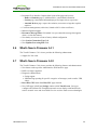
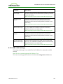
1 Welcome
20
1.1 Introduction
20
2 What's New
21
2.1 What's New in Firmware 4.1.0
2.1.1 Workstation and VDI
2.1.2 VDI-specific
2.1.3 Workstation-specific
21
21
22
22
2.2 What's New in Firmware 4.0.3
23
2.3 What's New in Firmware 4.0.2
23
2.4 What's New in Firmware 4.0.0
24
2.5 What's New in Firmware 3.5.0
25
2.6 What's New in Firmware 3.4.1
26
2.7 What's New in Firmware 3.4.0
26
3 PCoIP Management Tools
27
3.1 PCoIP Management Console
3.1.1 About the MC
3.1.2 Logging into the MC
3.1.3 MC Home Page
3.1.4 MC Profile Management Page
3.1.5 MC Manage Profiles Page
27
27
27
28
29
30
3.2 PCoIP Administrative Web Interface
3.2.1 About the AWI
3.2.2 Logging into the AWI
3.2.3 AWI Initial Setup Page
3.2.4 AWI Home Page
3.2.5 Failed Login Attempt Message
3.2.6 AWI Menus
34
34
34
35
36
39
40
3.3 PCoIP On Screen Display
3.3.1 About the OSD
3.3.2 Connecting to a Session
3.3.3 Disconnecting from a Session
3.3.4 Overlay Windows
3.3.5 OSD Menus
41
41
42
46
47
51
4 PCoIP Deployment Scenarios
52
4.1 PCoIP Endpoints
52
TER1206003 Issue 3
3
PCoIP® Zero Client and Host Administrator Guide
4.1.1 PCoIP Hardware Endpoints
4.1.2 PCoIP Software Endpoints
52
53
4.2 Connection Prerequisites
4.2.1 PCoIP Client–Host Card Connections
4.2.2 PCoIP Client–Published Desktop Connections
4.2.3 PCoIP Client–View Virtual Desktop Connections
54
54
55
55
4.3 Session Connection Types
4.3.1 Zero Client–Host Card Connections
55
55
4.3.2 Zero Client–Published Desktop Connections
4.3.3 Zero Client–View VDI Connections
57
59
4.4 Common LAN Scenarios
4.4.1 Connecting over a LAN
4.4.2 Zero Client to Host Card
4.4.3 Zero Client to Host Card via View Connection Server
4.4.4 Zero Client to Virtual Desktop via View Connection Server
60
60
61
61
62
4.5 Common Remote Access Scenarios
4.5.1 Connecting Remotely
4.5.2 Remote Zero Client to Host Card
4.5.3 Remote Zero Client to Host Card via Hardware VPN
4.5.4 Remote Zero Client to Host Card via 3rd Party Broker
4.5.5 Remote Zero Client to Host Card via View Security Server
4.5.6 Remote Zero Client to Virtual Desktop via View Security Server
4.5.7 Remote View Software Client to Host Card via View Security Server
4.5.8 Internal vs. External Zero Client to Host Card Connections Using View Connection Servers
63
63
64
66
67
68
70
71
72
4.6 Performance Optimization
4.6.1 Tuning for Performance
4.6.2 Configuring Windows Visual Effects
4.6.3 Optimizing PCoIP Sessions
4.6.4 Adjusting Session Settings
4.6.5 Reducing Display Factors
73
73
73
75
77
80
4.7 Network Design
4.7.1 Network Bandwidth Planning
4.7.2 Network Configuration
4.7.3 Network Latency and Jitter
4.7.4 Network Packet Loss
4.7.5 WAN Testing Guidelines
80
80
82
83
84
85
4.8 Security Considerations
4.8.1 PCoIP Zero Client Security Overview
4.8.2 Security Settings Checklist
86
86
87
5 GUI Reference
91
5.1 Initial Setup
5.1.1 AWI Host: Initial Setup Page
5.1.2 AWI Client: Initial Setup Page
91
91
92
5.2 Configuring the Network
94
TER1206003 Issue 3
4
PCoIP® Zero Client and Host Administrator Guide
5.2.1 MC: Network Settings
5.2.2 AWI: Network Settings
5.2.3 OSD: Network Settings
94
96
99
5.3 Label Settings
5.3.1 AWI: Label Settings
5.3.2 OSD: Label Settings
102
102
103
5.4 Access Settings
5.4.1 MC: Help for Access Settings
104
104
5.4.2 AWI: Access Settings
5.4.3 OSD: Access Settings
104
105
5.5 Configuring Device Discovery
5.5.1 MC: Discovery Settings
5.5.2 AWI: Discovery Settings
5.5.3 OSD: Discovery Settings
107
107
108
110
5.6 Configuring SNMP
5.6.1 MC: Help for SNMP Settings
5.6.2 AWI: SNMP Settings
111
111
111
5.7 Configuring a Session
5.7.1 Configuring a Session
5.7.2 MC: Direct to Host Session Settings
5.7.3 MC: Direct to Host Session + SLP Host Discovery Settings
5.7.4 MC: View Connection Server Session Settings
5.7.5 MC: View Connection Server + Auto-Logon Session Settings
5.7.6 MC: View Connection Server + Kiosk Session Settings
5.7.7 MC: View Connection Server + Imprivata OneSign Session Settings
5.7.8 MC: Connection Management Interface Settings
5.7.9 MC: PCoIP Connection Manager Session Settings
5.7.10 MC: PCoIP Connection Manager + Auto-Logon Session Settings
5.7.11 AWI Host: Direct from Client Session Settings
5.7.12 AWI Client: Direct to Host Session Settings
5.7.13 AWI Client: Direct to Host + SLP Host Discovery Session Settings
5.7.14 AWI Tera2 Client: PCoIP Connection Manager Session Settings
5.7.15 AWI Tera2 Client: PCoIP Connection Manager + Auto-Logon Session Settings
5.7.16 AWI Client: View Connection Server Session Settings
5.7.17 AWI Client: View Connection Server + Auto-Logon Session Settings
5.7.18 AWI Client: View Connection Server + Kiosk Session Settings
5.7.19 AWI Client: View Connection Server + Imprivata OneSign Session Settings
5.7.20 AWI Host: Connection Management Interface Session Settings
5.7.21 AWI Client: Connection Management Interface Session Settings
5.7.22 OSD: Direct to Host Session Settings
5.7.23 OSD: Direct to Host + SLP Host Discovery Session Settings
5.7.24 OSD Tera2: PCoIP Connection Manager Session Settings
5.7.25 OSD Tera2: PCoIP Connection Manager + Auto-Logon Session Settings
5.7.26 OSD: View Connection Server Session Settings
5.7.27 OSD: View Connection Server + Auto-Logon Session Settings
111
111
114
117
120
125
130
134
139
143
148
153
155
159
163
170
176
183
189
194
200
202
206
211
214
218
222
226
TER1206003 Issue 3
5
PCoIP® Zero Client and Host Administrator Guide
5.7.28 OSD: View Connection Server + Kiosk Session Settings
5.7.29 OSD: View Connection Server + Imprivata OneSign Session Settings
5.7.30 OSD: Connection Management Interface Session Settings
230
234
238
5.8 Configuring Session Encryption
5.8.1 MC: Encryption Settings
5.8.2 AWI: Help for Encryption Settings
241
241
242
5.9 Configuring Session Bandwidth
5.9.1 MC: Bandwidth Settings
243
243
5.9.2 AWI: Bandwidth Settings
245
5.10 Configuring the Language
5.10.1 MC: Language Settings
5.10.2 AWI Client: Language Settings
5.10.3 OSD: Language Settings
247
247
248
249
5.11 Configuring OSD Parameters
5.11.1 MC: OSD Settings
5.11.2 AWI Client: Help for OSD Settings
5.11.3 OSD: OSD Settings
250
250
251
251
5.12 Configuring Image Quality
5.12.1 MC: Image Settings
5.12.2 AWI Host: Image Settings
5.12.3 AWI Client: Image Settings
5.12.4 OSD: Image Settings
252
252
254
257
258
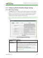
5.13 Configuring Monitor Emulation Display Settings
5.13.1 MC: Display Settings
5.13.2 AWI Tera1 Host: Monitor Emulation
5.13.3 AWI Tera2 Host: Monitor Emulation
260
260
261
262
5.14 Configuring Time
5.14.1 MC: Time Settings
5.14.2 AWI: Time Settings
264
264
265
5.15 Configuring Security
5.15.1 MC: Security Settings
5.15.2 AWI: Help for Security Settings
5.15.3 OSD: Help for Security Settings
266
266
268
268
5.16 Configuring Audio Permissions
5.16.1 MC: Audio Permissions
5.16.2 AWI Tera1 Host: Audio Permissions
5.16.3 AWI Tera2 Host: Audio Permissions
5.16.4 AWI Client: Audio Permissions
268
268
269
271
271
5.17 Configuring Power Settings
5.17.1 MC: Power Permissions
5.17.2 AWI Tera2 Host: Power Settings
5.17.3 AWI Tera1 Client: Power Settings
5.17.4 AWI Tera2 Client: Power Permissions
272
272
274
275
275
5.18 Configuring the Host Driver Function
277
TER1206003 Issue 3
6
PCoIP® Zero Client and Host Administrator Guide
5.18.1 MC: Host Driver Function
5.18.2 AWI Host: Host Driver Function
277
278
5.19 Configuring the Event Log
5.19.1 MC: Event Log Settings
5.19.2 AWI: Event Log Settings
5.19.3 OSD: Event Log Settings
279
279
280
282
5.20 Configuring Peripherals
5.20.1 MC: Peripheral Settings
283
283
5.20.2 AWI Client: Help for Peripheral Settings
284
5.21 Configuring IPv6
5.21.1 MC: IPv6 Settings
5.21.2 AWI: IPv6 Settings
5.21.3 OSD: IPv6 Settings
284
284
286
288
5.22 Configuring SCEP
5.22.1 MC: SCEP Settings
5.22.2 AWI Tera2 Client: SCEP Settings
5.22.3 OSD Tera2: SCEP Settings
290
290
291
292
5.23 Configuring the Display Topology
5.23.1 MC: Display Topology Settings
5.23.2 OSD Dual-display: Display Topology Settings
5.23.3 OSD Quad-display: Display Topology Settings
293
293
297
300
5.24 Uploading an OSD Logo
5.24.1 MC: OSD Logo Settings
5.24.2 AWI Client: OSD Logo Settings
302
302
303
5.25 Uploading Firmware
5.25.1 MC: Firmware Management
5.25.2 AWI: Firmware Upload Settings
304
304
305
5.26 Configuring USB Permissions
5.26.1 MC: USB Permissions
5.26.2 AWI Host: USB Permissions
5.26.3 AWI Client: USB Permissions
306
306
309
312
5.27 Configuring the Certificate Store
5.27.1 MC: Certificate Store Management
5.27.2 AWI: Certificate Upload Settings
316
316
318
5.28 Configuring OSD Display Settings
5.28.1 OSD Dual-display: Display Settings
5.28.2 OSD Quad-display: Display Settings
5.28.3 OSD TERA2321: Display Settings
320
320
323
326
5.29 Configuring Password Parameters (AWI/OSD)
5.29.1 OSD: Password Settings
329
329
5.30 Configuring Reset Parameters (AWI/OSD)
5.30.1 AWI Client: Parameter Reset Settings
5.30.2 AWI Host: Parameter Reset Settings
330
330
331
TER1206003 Issue 3
7
PCoIP® Zero Client and Host Administrator Guide
5.30.3 OSD: Parameter Reset Settings
332
5.31 Viewing Diagnostics (AWI/OSD)
5.31.1 AWI: Help for Event Log Settings
5.31.2 OSD: Help for Event Log Settings
5.31.3 AWI Host: Session Control Settings
5.31.4 AWI Client: Session Control Settings
5.31.5 AWI Host: Session Statistics Settings
5.31.6 AWI Client: Session Statistics Settings
332
332
333
333
333
334
337
5.31.7 OSD:Session Statistics Settings
5.31.8 AWI Host: Host CPU Settings
5.31.9 AWI Client: Audio Settings
5.31.10 AWI Client: Display Settings
5.31.11 AWI: PCoIP Processor Settings
5.31.12 OSD: PCoIP Processor Settings
5.31.13 OSD: Ping Settings
340
341
342
343
344
344
345
5.32 Viewing Information (AWI/OSD)
5.32.1 AWI: Version Information
5.32.2 Viewing the Version Information
5.32.3 AWI Host: Attached Devices Information
5.32.4 AWI Client: Attached Devices Information
346
346
348
349
350
5.33 Configuring User Settings (OSD)
5.33.1 OSD: Certificate Checking Settings
5.33.2 MC: Help for Certificate Checking Settings
5.33.3 AWI Client: Help for Certificate Checking Settings
5.33.4 OSD: Mouse Settings
5.33.5 OSD: Keyboard Settings
5.33.6 OSD: Help for Image Settings
5.33.7 OSD: Help for Display Topology Settings
5.33.8 OSD: Touch Screen Settings
351
351
352
352
353
353
354
355
355
6 "How To" Topics
357
6.1 Displaying Processor Information
357
6.2 Configuring Syslog Settings
6.2.1 Setting up Syslog from the AWI
6.2.2 Setting up Syslog from the MC
359
360
360
6.3 Uploading Firmware
6.3.1 Uploading a Firmware Release to a Zero Client
6.3.2 Upload a Firmware Release to a Host
360
360
361
6.4 Configuring 802.1x Network Device Authentication
6.4.1 Prerequisites
6.4.2 Procedure
361
361
362
6.5 Setting up a Touch Screen Display
6.5.1 Installing the Touch Screen to the Zero Client
6.5.2 Setting up the Touch Screen as a Bridged Device
366
366
366
TER1206003 Issue 3
8
PCoIP® Zero Client and Host Administrator Guide
6.5.3 Configuring the Zero Client to Automatically Log into a Host Brokered by a Connection Manager
367
7 Technology Reference
369
7.1 APEX 2800 PCoIP Server Offload Card
369
7.2 PCoIP Connection Brokers
369
7.3 DVI and DisplayPort Interfaces
7.3.1 Support for 2560x1600 Display Resolution
369
369
7.4 Host Cards
371
7.5 PCoIP Software Session Variables
371
7.6 PCoIP Packet Format
7.6.1 UDP-encapsulated ESP Packet Format
7.6.2 IPsec ESP Packet Format
371
372
372
7.7 Syslog
372
7.8 Zero Clients
373
8 Glossary of Acronyms
374
TER1206003 Issue 3
9
PCoIP® Zero Client and Host Administrator Guide
Table of Figures
Figure 2-1: MC Login Page
28
Figure 2-2: MC Home Page
29
Figure 2-3: MC Profile Management Page
30
Figure 2-4: MC Manage Profiles Page
31
Figure 2-5: Edit Properties Link
31
Figure 2-6: Set Properties Page for Network Configuration
32
Figure 2-7: MC Manage Profiles Page – Configured
33
Figure 2-8: AWI Log In Page
35
Figure 2-9: AWI Host: Home Page
36
Figure 2-10: AWI Client: Home Page
37
Figure 2-11: Failed Login Attempt Warning
40
Figure 2-12: AWI Menu Overview
41
Figure 2-13: OSD Main Window
42
Figure 2-14: OSD Direct to Host Connect Window
43
Figure 2-15: OSD Connection Status
43
Figure 2-16: OSD View Connection Server Connect Window
44
Figure 2-17: Virtual Desktop Login Page
44
Figure 2-18: OSD View Connection Server Certificate Warning
45
Figure 2-19: OSD Login Screen with Insecure Warning
45
Figure 2-20: OSD VMware View Page
46
Figure 2-21: Zero Client Control Panel
47
Figure 2-22: Display Link Training Failed Overlay
48
Figure 2-23: Half Duplex Overlay
48
Figure 2-24: Network Connection Lost Overlay
48
Figure 2-25: No Support Resolutions Found Overlay
49
Figure 2-26: Preparing Desktop Overlay
49
Figure 2-27: USB Device Not Authorized Overlay
49
Figure 2-28: USB Over Current Notice Overlay
49
Figure 2-29: USB Device Not Supported Behind a High-speed Hub Overlay
50
Figure 2-30: Resolution Not Supported Overlay
50
Figure 2-31: No Source Signal Overlay
50
Figure 2-32: Source Signal on Other Port Overlay
51
TER1206003 Issue 3
10
PCoIP® Zero Client and Host Administrator Guide
Figure 2-33: OSD Options Menu
51
Figure 3-1: PCoIP Hardware Endpoints
52
Figure 3-2: PCoIP Software Endpoints
54
Figure 3-3: Zero Client to Host Card (LAN)
61
Figure 3-4: View – Zero Client to Host Card via View Connection Server
62
Figure 3-5: View – Zero Client to Virtual Desktop via View Connection Server
63
Figure 3-6: Tera2 Zero Client to Host Card (WAN)
65
Figure 3-7: Remote PCoIP Sessions with Multiple Tera2 Devices
65
Figure 3-8: Hardware VPN – Zero Client to Host Card
66
Figure 3-9: Zero Client to Host Card via 3rd Party Broker (Tera2 only)
68
Figure 3-10: View – Zero Client to Host Card via View Security/Connection Server
69
Figure 3-11: View – Zero Client to VDI Desktop via View Security/Connection Server
70
Figure 3-12: View – Soft Client to Host Card via View Security Server
71
Figure 4-1: AWI Host Initial Setup Page
91
Figure 4-2: AWI Client Initial Setup Page
93
Figure 4-3: MC Network Configuration
95
Figure 4-4: AWI Network Page
97
Figure 4-5: OSD Network Page
100
Figure 4-6: AWI Label Page
102
Figure 4-7: OSD Label Page
103
Figure 4-8: AWI Access Page
105
Figure 4-9: OSD Access Page
106
Figure 4-10: MC Discovery Configuration
107
Figure 4-11: AWI Discovery Page
109
Figure 4-12: OSD Discovery Page
110
Figure 4-13: AWI SNMP Page
111
Figure 4-14: MC Session Connection Type – Direct to Host
114
Figure 4-15: MC Session Connection Type – Direct to Host + SLP Host Discovery
118
Figure 4-16: MC Session Connection Type – View Connection Server
121
Figure 4-17: MC Session Connection Type – View Connection Server + Auto-Logon
126
Figure 4-18: MC Session Connection Type – View Connection Server + Kiosk
131
Figure 4-19: MC Session Connection Type – View Connection Server + Imprivata OneSign 135
Figure 4-20: MC Session Connection Type – Connection Management Interface
140
Figure 4-21: MC Session Connection Type – PCoIP Connection Manager
144
Figure 4-22: MC Session Connection Type – PCoIP Connection Manager + Auto-Logon
149
TER1206003 Issue 3
11
PCoIP® Zero Client and Host Administrator Guide
Figure 4-23: AWI Session Connection Type – Direct from Client
153
Figure 4-24: AWI Session Connection Type – Direct to Host
155
Figure 4-25: AWI Session Connection Type – Direct to Host + SLP Host Discovery
160
Figure 4-26: AWI Session Connection Type – PCoIP Connection Manager
164
Figure 4-27: Enable Self Help Link Options
169
Figure 4-28: AWI Session Connection Type – PCoIP Connection Manager + Auto-Logon
171
Figure 4-29: AWI Session Connection Type – View Connection Server
177
Figure 4-30: Enable Self Help Link Options
182
Figure 4-31: AWI Session Connection Type – View Connection Server + Auto-Logon
184
Figure 4-32: AWI Session Connection Type – View Connection Server + Kiosk
190
Figure 4-33: AWI Session Connection Type – View Connection Server + Imprivata OneSign 195
Figure 4-34: AWI Session Connection Type – Connection Management Interface (Host)
201
Figure 4-35: AWI Session Connection Type – Connection Management Interface (Client)
203
Figure 4-36: OSD Session Connection Type – Direct to Host
207
Figure 4-37: Advanced Settings
207
Figure 4-38: OSD Session Connection Type – Direct to Host + SLP Host Discovery
211
Figure 4-39: Advanced Settings
212
Figure 4-40: OSD Session Connection Type – PCoIP Connection Manager
214
Figure 4-41: Advanced Settings
215
Figure 4-42: OSD Session Connection Type – PCoIP Connection Manager + Auto-Logon
218
Figure 4-43: Advanced Settings
219
Figure 4-44: OSD Session Connection Type – View Connection Server
222
Figure 4-45: Advanced Settings
223
Figure 4-46: OSD Session Connection Type – View Connection Server + Auto-Logon
226
Figure 4-47: Advanced Settings
227
Figure 4-48: OSD Session Connection Type – View Connection Server + Kiosk
230
Figure 4-49: Advanced Settings
231
Figure 4-50: OSD Session Connection Type – View Connection Server + Imprivata OneSign 234
Figure 4-51: Advanced Settings
235
Figure 4-52: OSD Session Connection Type – Connection Management Interface
238
Figure 4-53: Advanced Settings
239
Figure 4-54: MC Encryption Configuration
241
Figure 4-55: MC Bandwidth Configuration
243
Figure 4-56: AWI Bandwidth Page
246
Figure 4-57: MC Language Configuration
248
TER1206003 Issue 3
12
PCoIP® Zero Client and Host Administrator Guide
Figure 4-58: AWI Client Language Page
249
Figure 4-59: OSD Language Page
250
Figure 4-60: MC OSD Configuration
251
Figure 4-61: OSD OSD Page
252
Figure 4-62: MC Image Configuration
253
Figure 4-63: AWI Host Image Page
255
Figure 4-64: AWI Host Image Page – Use Client Image Settings Disabled
255
Figure 4-65: AWI Client Image Page
257
Figure 4-66: OSD Image Page
259
Figure 4-67: MC Monitor Emulation Page
260
Figure 4-68: AWI Tera1 Host Monitor Emulation Page
262
Figure 4-69: AWI Tera2 Host Monitor Emulation Page
263
Figure 4-70: MC Time Configuration
264
Figure 4-71: AWI Time Page
265
Figure 4-72: MC Security Configuration
267
Figure 4-73: MC Audio Permissions
269
Figure 4-74: AWI Tera1 Host Audio Page
270
Figure 4-75: AWI Tera2 Host Audio Page
271
Figure 4-76: AWI Client Audio Page
272
Figure 4-77: MC Power Permissions
273
Figure 4-78: AWI Tera2 Host Power Page
274
Figure 4-79: AWI Tera1 Client Power Page
275
Figure 4-80: AWI Tera2 Client Power Page
276
Figure 4-81: MC Host Driver Configuration
277
Figure 4-82: AWI Host Driver Function Page
278
Figure 4-83: MC Event Log Control
279
Figure 4-84: AWI Event Log Page – Event Log Selected
281
Figure 4-85: OSD Event Log Page
283
Figure 4-86: MC Peripheral Configuration
284
Figure 4-87: MC IPv6 Configuration
285
Figure 4-88: AWI IPv6 Page
287
Figure 4-89: OSD IPv6 Page
289
Figure 4-90: MC SCEPConfiguration
291
Figure 4-91: AWI SCEP Page
292
Figure 4-92: OSD Tera2 SCEP Page
293
TER1206003 Issue 3
13
PCoIP® Zero Client and Host Administrator Guide
Figure 4-93: MC Display Topology Configuration
294
Figure 4-94: OSD Tera1 Display Topology Page
298
Figure 4-95: OSD Tera2 Display Topology Page
300
Figure 4-96: MC Profile OSD Logo Configuration
302
Figure 4-97: MC Add OSD Logo Configuration
303
Figure 4-98: AWI Client OSD Logo Upload Page
303
Figure 4-99: MC Profile Firmware Configuration
304
Figure 4-100: MC Link to Imported Firmware
304
Figure 4-101: MC Link to Imported Firmware – Configured
305
Figure 4-102: AWI Firmware Upload Page
305
Figure 4-103: MC Profile Zero Client USB Configuration
306
Figure 4-104: USB Authorization – Add New
308
Figure 4-105: USB Unauthorization – Add New
308
Figure 4-106: USB Bridged – Add New
308
Figure 4-107: AWI Host USB Page
310
Figure 4-108: Device Class Parameters
311
Figure 4-109: Device ID Parameters
311
Figure 4-110: AWI Client USB Page
313
Figure 4-111: Device Class Parameters
315
Figure 4-112: Device ID Parameters
315
Figure 4-113: USB Bridged Parameters
316
Figure 4-114: MC Certificate Store Configuration
317
Figure 4-115: MC Add Certificate to Store
317
Figure 4-116: MC Certificate Store
318
Figure 4-117: AWI Certificate Upload Page
319
Figure 4-118: OSD Tera1Display Page
321
Figure 4-119: OSD Tera2 Display Page
324
Figure 4-120: OSD Tera1Display Page
327
Figure 4-121: OSD Change Password Page
329
Figure 4-122: AWI Client Reset Page
330
Figure 4-123: AWI Host Reset Page
331
Figure 4-124: OSD Reset Page
332
Figure 4-125: AWI Host Session Control Page
333
Figure 4-126: AWI Client Session Control Page
334
Figure 4-127: AWI Host Session Statistics Page
335
TER1206003 Issue 3
14
PCoIP® Zero Client and Host Administrator Guide
Figure 4-128: AWI Client Session Statistics Page
338
Figure 4-129: OSD Session Statistics Page
341
Figure 4-130: AWI Host CPU Page
342
Figure 4-131: AWI Client Audio Page
343
Figure 4-132: AWI Client Display Page
343
Figure 4-133: AWI PCoIP Processor Page
344
Figure 4-134: OSD PCoIP Processor Page
345
Figure 4-135: OSD Ping Page
346
Figure 4-136: AWI Version Page
347
Figure 4-137: OSD Version Page
348
Figure 4-138: AWI Host Attached Devices Page
349
Figure 4-139: AWI Client Attached Devices Page
350
Figure 4-140: OSD VMware View Page
352
Figure 4-141: OSD Mouse Page
353
Figure 4-142: OSD Keyboard Page
354
Figure 4-143: OSD Touch Screen Page
355
Figure 4-144: Processor Information on AWI Home Page
357
Figure 4-145: Processor Family Information on AWI Version Page
358
Figure 4-146: Processor Family Information on OSD Version Page
359
Figure 5-1: DVI and DisplayPort Connectors for 2560x1600 Resolution
370
Figure 5-2: UDP-encapsulated ESP Packet Format
372
Figure 5-3: IPsec ESP Packet Format
372
TER1206003 Issue 3
15
PCoIP® Zero Client and Host Administrator Guide
Table of Tables
Table 2-1: AWI Home Page Statistics
37
Table 3-1: Supported Resolutions for PCoIP Host Cards and Zero Clients
53
Table 3-2: PCoIP Session Settings
78
Table 3-3: PCoIP Zero Client Security Settings Checklist
87
Table 4-1: Audio Parameters
91
Table 4-2: Network Parameters
92
Table 4-3: Session Parameters
92
Table 4-4: Audio Parameters
93
Table 4-5: Network Parameters
93
Table 4-6: Session Parameters
94
Table 4-7: MC Network Configuration Parameters
95
Table 4-8: AWI Network Page Parameters
97
Table 4-9: OSD Network Page Parameters
100
Table 4-10: AWI Label Page Parameters
102
Table 4-11: OSD Label Page Parameters
104
Table 4-12: AWI Access Page Parameters
105
Table 4-13: OSD Access Page Parameters
106
Table 4-14: MC Discovery Configuration Parameters
108
Table 4-15: AWI Discovery Page Parameters
109
Table 4-16: OSD Discovery Page Parameter
110
Table 4-17: AWI SNMP Page Parameter
111
Table 4-18: Direct Session Connections
112
Table 4-19: PCoIP Connection Manager Connections
112
Table 4-20: VMware View Connections
113
Table 4-21: Connection Management Interface Connections
114
Table 4-22: MC Session Configuration Parameters
115
Table 4-23: MC Session Configuration Parameters
118
Table 4-24: MC Session Configuration Parameters
121
Table 4-25: MC Session Configuration Parameters
126
Table 4-26: MC Session Configuration Parameters
131
Table 4-27: MC Session Configuration Parameters
135
Table 4-28: MC Session Configuration Parameters
140
TER1206003 Issue 3
16
PCoIP® Zero Client and Host Administrator Guide
Table 4-29: MC Session Configuration Parameters
144
Table 4-30: MC Session Configuration Parameters
149
Table 4-31: AWI Session Page Parameters
154
Table 4-32: AWI Session Page Parameters
155
Table 4-33: AWI Session Page Parameters
160
Table 4-34: AWI Session Page Parameters
164
Table 4-35: AWI Session Page Parameters
171
Table 4-36: AWI Session Page Parameters
177
Table 4-37: AWI Session Page Parameters
184
Table 4-38: AWI Session Page Parameters
190
Table 4-39: AWI Session Page Parameters
195
Table 4-40: AWI Session Page Parameters
201
Table 4-41: AWI Session Page Parameters
203
Table 4-42: OSD Session Page Parameters
208
Table 4-43: OSD Session Page Parameters
212
Table 4-44: OSD Session Page Parameters
215
Table 4-45: OSD Session Page Parameters
219
Table 4-46: OSD Session Page Parameters
223
Table 4-47: OSD Session Page Parameters
227
Table 4-48: OSD Session Page Parameters
231
Table 4-49: OSD Session Page Parameters
235
Table 4-50: AWI Session Page Parameters
239
Table 4-51: MC Encryption Configuration Parameters
242
Table 4-52: MC Bandwidth Configuration Parameters
244
Table 4-53: AWI Bandwidth Parameters
246
Table 4-54: MC Language Configuration Parameters
248
Table 4-55: AWI Client Language Parameters
249
Table 4-56: OSD Language Parameters
250
Table 4-57: MC Language Configuration Parameters
251
Table 4-58: OSD OSD Parameters
252
Table 4-59: MC Image Configuration Parameters
253
Table 4-60: AWI Host Image Page Parameters
255
Table 4-61: AWI Client Image Page Parameters
257
Table 4-62: OSD Image Page Parameters
259
Table 4-63: MC Monitor Parameters
260
TER1206003 Issue 3
17
PCoIP® Zero Client and Host Administrator Guide
Table 4-64: AWI Tera1 Host Monitor Parameters
262
Table 4-65: AWI Tera2 Host Monitor Parameters
263
Table 4-66: MC Time Configuration Parameters
264
Table 4-67: AWI Time Page Parameters
266
Table 4-68: MC Security Configuration Parameters
267
Table 4-69: MC Audio Permissions Parameters
269
Table 4-70: AWI Tera1 Host Audio Page Parameters
270
Table 4-71: AWI Tera2 Host Audio Page Parameters
271
Table 4-72: AWI Client Audio Page Parameters
272
Table 4-73: MC Power Permissions Parameters
273
Table 4-74: AWI Tera2 Host Power Page Parameters
274
Table 4-75: AWI Tera1 Client Power Page Parameters
275
Table 4-76: AWI Tera2 Client Power Page Parameters
276
Table 4-77: MC Host Driver Configuration Parameters
278
Table 4-78: AWI Host Driver Function Parameters
279
Table 4-79: MC Event Log Control Parameters
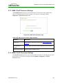
280
Table 4-80: AWI Event Log Page Parameters
281
Table 4-81: OSD Event Log Page Parameters
283
Table 4-82: MC Peripheral Configuration Parameters
284
Table 4-83: MC IPv6 Configuration Parameters
285
Table 4-84: AWI IPv6 Page Parameters
287
Table 4-85: OSD IPv6 Page Parameters
289
Table 4-86: MC SCEP Configuration Parameters
291
Table 4-87: AWI SCEP Parameters
292
Table 4-88: OSD Tera2 SCEP Page Parameters
293
Table 4-89: MC Display Topology Configuration Parameters
294
Table 4-90: OSD Tera1 Display Topology Page Parameters
298
Table 4-91: OSD Tera2 Display Topology Page Parameters
301
Table 4-92: MC Add OSD Logo Configuration Parameters
303
Table 4-93: AWI Client OSD Logo Upload Page Parameters
304
Table 4-94: MC Link to Imported Firmware Parameters
305
Table 4-95: AWI Firmware Upload Page Parameters
306
Table 4-96: MC Profile Zero Client USB Configuration Parameters
307
Table 4-97: Add Profile USB – Add New Parameters
309
Table 4-98: AWI Host USB Page Parameters
311
TER1206003 Issue 3
18
PCoIP® Zero Client and Host Administrator Guide
Table 4-99: USB Authorized/Unauthorized Devices Parameters
312
Table 4-100: AWI Client USB Page Parameters
314
Table 4-101: USB Authorized/Unauthorized Devices Parameters
315
Table 4-102: USB Bridged Devices Parameters
316
Table 4-103: MC Certificate Store Configuration Parameters
317
Table 4-104: MC Add Certificate to Store Parameters
318
Table 4-105: AWI Certificate Upload Page Parameters
319
Table 4-106: OSD Tera1 Display Page Parameters
322
Table 4-107: OSD Tera2 Display Page Parameters
325
Table 4-108: OSD Tera1 Display Page Parameters
328
Table 4-109: OSD Change Password Page Parameters
330
Table 4-110: AWI Client Reset Parameters
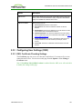
331
Table 4-111: AWI Host Reset Parameters
331
Table 4-112: OSD Reset Parameters
332
Table 4-113: AWI Host Session Control Page Parameters
333
Table 4-114: AWI Client Session Control Page Parameters
334
Table 4-115: AWI Host Session Statistics Page Parameters
335
Table 4-116: AWI Client Session Statistics Page Parameters
339
Table 4-117: OSD Session Statistics Page Parameters
341
Table 4-118: AWI Host CPU Page Parameters
342
Table 4-119: AWI Client Display Page Parameters
343
Table 4-120: AWI PCoIP Processor Page Parameters
344
Table 4-121: Ping Page Parameters
346
Table 4-122: AWI Version Page Parameters
347
Table 4-123: OSD Version Page Parameters
348
Table 4-124: AWI Host: Attached Devices Page Information
350
Table 4-125: AWI Client: Attached Devices Page Information
350
Table 4-126: OSD VMware View Page Parameters
352
Table 4-127: OSD Mouse Page Parameters
353
Table 4-128: OSD Keyboard Page Parameters
354
Table 4-129: OSD Touch Screen Page Parameters
355
TER1206003 Issue 3
19
PCoIP® Zero Client and Host Administrator Guide
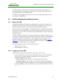
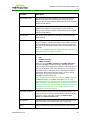
1
Welcome
1.1
Introduction
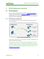
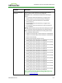
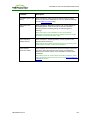
Welcome to Teradici's PCoIP Zero Client and Host Administrator Online Help. This help
system explains how to configure PCoIP device firmware so you can access and manage the
hosts and zero clients in your PCoIP deployment. It comprises the following main sections:
l
l
l
l
l
l
What's New: This section explains the new features for each firmware release, and
contains links to topics that provide more information about these features.
PCoIP Management Tools: This section describes how to access and use the following
PCoIP management tools:
l Management Console (MC): The MC lets you centrally control and manage the
devices in your PCoIP deployment. This help system explains how to configure a
profile (a collection of device configuration settings), which you can then assign to a
specific PCoIP group (a set of one or more hosts or clients). The MC is the best tool
for medium to large deployments, and is often used in conjunction with a connection
broker. For further details, see About the MC.
l Administrative Web Interface (AWI): The AWI lets you use an Internet browser to
remotely access and configure a specific client or host. For further details, see About
the AWI.
l On Screen Display (OSD): The OSD is the graphical user interface (GUI) embedded
within a client. It is used to connect the client to a virtual desktop or to a host in a
remote workstation. It is also used to configure the client, and has a subset of the
configuration parameters available in the MC and AWI. For further details, see
About the OSD.
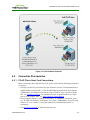
PCoIP Deployment Scenarios: This section illustrates and describes the most common
ways to deploy the hosts and clients in your PCoIP network. Configuration steps are
included for each scenario, with links to topics in the GUI Reference where you can find
detailed information. The scenarios are the best place to start when configuring a new
deployment.
GUI Reference: This section is a detailed reference that describes each configuration
parameter that appears in the MC, AWI, and OSD pages. You can use this reference
when configuring a device profile using the MC, or when configuring a single device
using the AWI or OSD. The GUI Reference is organized by the categories listed in the
MC's Manage Profiles page, but also has special sections for AWI and OSD menus that
do not corresponding pages in the MC.
"How To" Topics: This section contains procedures for common configuration tasks.
Technology Reference: This section contains definitions for some of the terminology
used in the help system.
TER1206003 Issue 3
20
PCoIP® Zero Client and Host Administrator Guide
2
What's New
2.1
What's New in Firmware 4.1.0
2.1.1
Workstation and VDI
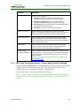
New Security Features for Zero Clients
l
l
l
l
Failed attempts to access the AWI, OSD, or MC are now logged. The next time users
log in, a warning message displays to inform them of these attempts. See Failed Login
Attempt Message for an example of this message displayed on the AWI.
After three failed attempts to access the AWI or OSD, each subsequent failed attempt
will require additional time to complete.
A new Access page containing the following features is available for the AWI and
OSD:
l You can now disable AWI and/or MC access to a zero client to prevent changes to
the client's configuration.
Note: If the Options > Configuration menus on the OSD are also hidden for the zero
client, then only one of these management tools can be disabled at any one time.
l You can force the changing of the administrative password the next time the AWI or
OSD is accessed.
Simple Certificate Enrollment Protocol (SCEP) is now supported for Tera2 zero clients.
From the new SCEP page for the AWI and OSD, you can configure a zero client to
automatically obtain certificates from a SCEP server. From the new MC SCEP page,
you can configure a profile to obtain certificates for a group of zero clients.
Other New Features
l
l
Session pages for all management tools have the following new options:
l For Tera2 zero clients, two new session connection types (PCoIP Connection
Manager and PCoIP Connection Manager + Auto-Logon) have been added. You
can configure this feature from thec AWI, OSD, and MC Session pages.
Note: The PCoIP Connection Manager can be used in the future to broker PCoIP
sessions for Teradici solutions such as the Teradici Arch™ published desktop
solution.
l For all zero client and host card session connection types, you can now populate the
Differentiated Services Code Point (DSCP) field in the IP header to allow
intermediate network nodes to prioritize PCoIP traffic accordingly. You can also
enable transport congestion notification to allow PCoIP endpoints to react accordingly
if an intermediate network node sets the congestion notification bit in either the IP
header or PCoIP transport header. These settings are available at the bottom of the
Advanced Options section on all Session pages.
The maximum size for certificates has been increased in this release. From the AWI, the
maximum certificate size you can upload to a zero client or host card is now 10,239
bytes (up from 6,143 bytes). From the MC, the maximum certificate size you can upload
TER1206003 Issue 3
21
PCoIP® Zero Client and Host Administrator Guide
l
l
l
2.1.2
VDI-specific
l
l
2.1.3
to a profile is now 8,176 (up from 6,143 bytes). You can upload up to 16 certificates per
device as long as the maximum storage space of 98,112 bytes is not exceeded. Note that
if SCEP is enabled, you can only upload a maximum of 14 additional certificates since
the SCEP server always installs two certificates in a device.
The zero client and host card Power pages have been moved from the AWI
Permissions menu to the Configuration menu and have the following new settings:
l For zero clients, you can now configure a screen saver timeout to put attached
displays in low-power mode after a specified period of inactivity. For Tera2 zero
clients that support powering off, you can configure an auto power-off timeout to
power down the client after a period of inactivity when users are not in session. The
MC Power page also has the new auto power-off timeout option for a Tera2 zero
client profile.
l For Tera2 host cards, you can select whether to wake up the host from sleep mode
using the remote power button input or the PCIe bus input.
The following new display features are included in this release:
l A new display cloning mode for TERA2321 zero clients lets you mirror images on
the primary display to the secondary display (e.g., for multiple digital signs). You can
enable display cloning from the OSD Display page, or you can configure a profile for
TERA2321 zero clients with this feature from the MC Display page.
l For Tera2 host cards, you can now enable a host hot plug delay to resolve black
screen issues with certain Linux GPU driver timing expectations. This feature is
available from the AWI Monitor Emulation page, or you can configure a profile for
Tera2 host cards with this feature from the MC Display page.
Portuguese (Brazilian ABNT) and Slovak (AWERTY and AWERTZ) keyboard layouts
are now supported for Tera1 and Tera2 zero clients.
The following smart cards and eToken devices are now supported:
l SafeNet SC650 smart cards with SafeNet PKI applet and SHAC middleware (Tera1
and Tera2 zero clients)
l Atos CardOS smart cards (Tera2 zero clients only)
l eToken 72k Pro USB user authentication devices (Tera1 and Tera2 zero clients)
A new Use Existing Setting option has been added to specify whether the proximity
card reader beeps when a valid card is tapped on the reader. When selected, this option
uses the proximity card setting that has been configured outside of the zero client. This
feature is available from the AWI View Connection Server + Imprivata OneSign Session
page (Pre-session Reader Beep field), or you can configure a profile for zero clients
with this feature from the MC View Connection Server + Imprivata OneSign Session
page (Proximity Reader Beep Mode field).
Workstation-specific
l
You can now configure "host wake" options from the OSD Direct to Host Session page.
Previously, this feature was only available on the AWI and MC.
TER1206003 Issue 3
22
PCoIP® Zero Client and Host Administrator Guide
l
2.2
Local termination of keyboards and mice behind USB hubs is now supported provided all
devices attached to USB hub are HID keyboards and mice.
What's New in Firmware 4.0.3
The Teradici firmware 4.0.3 release supports the new Tera2 processor family to deliver
enhanced display capabilities, imaging performance, memory, power management, and
other important functions.
For example, the TERA2140 zero client can support up to four displays (DVI-D or
DisplayPort) and can perform image encoding at speeds of up to 300 million pixels per
second (Mpps) for remote workstations and 50 Mpps for virtual desktops. For complete
product details on second-generation PCoIP zero clients and host cards containing these new
Tera2 processors, see the Teradici website at http://www.teradici.com. For a list of all the
host cards and zero clients supported in this firmware release, see PCoIP Host Cards and
Zero Clients.
Note: For the Tera1 processor family, please use the firmware 4.0.2 release.
2.3
What's New in Firmware 4.0.2
The Teradici firmware 4.0.2 release provides the following features and enhancements:
l
l
l
l
Processor family information: You can now display information about the processor
family and chipset in your device a number of ways. For details, see Displaying
Processor Information.
Display topology configuration enhancements: To support the new Tera2 display
capabilities, the Display Topology Configuration page on the Management Console (MC)
and the Display Topology settings on the On Screen Display (OSD) now let you
configure layout, alignment, and resolution properties for dual-display and quad-display
topologies.
Preferred resolution override enhancements: In this release, an expanded list of
default resolutions is included when you configure a zero client to advertise default
Extended Display Identification Data (EDID) information to the graphics processing unit
(GPU) in a host workstation. For Tera2 clients, you can now configure preferred
(default) resolutions for up to four displays. For details, see OSD Tera2: Display
Settings.
Expanded list of test display resolutions: The Display page on the Administrator Web
Interface (AWI) now contains an expanded list of display resolutions for viewing a test
pattern on a zero client. For details about how to configure a test pattern, see AWI
TER1206003 Issue 3
23
PCoIP® Zero Client and Host Administrator Guide
Client: Display Settings.
l
l
l
l
l
2.4
New Tera2 disconnect options: When a user is in a session with a remote workstation,
pressing the connect/disconnect button on a Tera2 zero client pops up a new dialog that
lets the user select whether to disconnect from the session or to power off the remote
workstation. Users can also use a Ctrl+Alt+F12 hotkey sequence to display this pop-up
dialog. For details about this new feature, see Disconnecting from a Session.
Enhanced OSD messaging: Messaging on the OSD has been enhanced with new
overlay windows and also new in-line messages that appear on the OSD's Connect
page. For example, if a user does not enter the correct user name or password, or if the
Caps Lock key is on, a message displays above the Connect button on this page to alert
the user. Network connection lost/down/up messages also display in this location,
replacing the network icons that used to appear in the lower right-hand corner. For
details, see Connecting to a Session and Overlay Windows.
Management Console cached VCS address enhancement: You can now configure up
to 25 cached View Connection Server addresses from the Management Console's
Session Configuration – View Connection Server page. These servers are displayed in
a drop-down list on the OSD Connect page when users use a VMware View
Connection Server to connect to a virtual desktop. For details, see MC: View Connection
Server Session Settings.
Imprivata OneSign configuration enhancements: New parameters on the View
Connection Server – Imprivata OneSign page allow you to configure a OneSign server
desktop name. When the desktop pool list includes a pool with this name, the zero client
will start a session with this desktop. You can configure a profile with this option from
the MC: View Connection Server + Imprivata OneSign page, or you can configure a
specific zero client from the AWI Client: view Connection Server + Imprivata Onesign
page or OSD: View Connection Server + Imprivata Onesign page.
Online help for administrators: PCoIP zero client and host card administrator
documentation is now delivered as online help in this release, with a full GUI Reference
that includes how to configure device firmware using three PCoIP administrator tools—
the MC, the AWI, and the OSD. It also contains topics for common PCoIP device
deployment scenarios, providing illustrations, descriptions, and links to configuration
details for each one.
What's New in Firmware 4.0.0
The Teradici firmware 4.0.0 release provides the following features and enhancements:
l
Security enhancement when connecting to VMware View Connection server: New VCS
Certificate Check Mode options allow users to configure the client to reject, warn, or
allow an unverifiable connection. This feature is available from both the Administrator
Web Interface (AWI) and the Online Screen Display (OSD). You can also enable the
TER1206003 Issue 3
24
PCoIP® Zero Client and Host Administrator Guide
l
l
l
l
l
l
l
l
l
l
2.5
VCS Certificate Check Mode Lockout option on the AWI to prevent users from
changing the VCS Certificate Check Mode options from the OSD.
Security enhancement: TLS 1.2 and Suite-B TLS ciphers are now supported for zero
clients and host cards.
New "Preparing desktop..." overlay can be enabled for all connection types.
When configuring a View Connection Server + Imprivata OneSign connection from
the AWI, you can now configure the client to connect to any appliance or only to
appliances with verified certificates.
When configuring a Direct to Host session, the Wake host from low power state
setting in the advanced options now lets you configure the host's IP address as well as its
MAC address. In addition, the Peer MAC Address field has been removed from the
OSD Direct to Host advanced settings options. The wake host feature is now configured
from the AWI only.
OSD advanced View Connection Server options now contain a new Desktop Name to
Select setting. Previously, this setting was only available from the AWI.
The OSD now lets you configure a View Connection Server + Auto-Logon connection.
Previously, this connection could only be configured using the AWI and PCoIP
Management Console (MC).
The default OSD screen-saver timeout value has been changed to 300 seconds.
Previously, this setting was disabled by default (i.e., set to 0 seconds).
New OSD Display options let you configure the native resolution of a display when the
display cannot be detected and default EDID information is sent.
OSD Display Topology enhancements make the topology easier to configure. In
addition, you no longer have to reboot the zero client after changing the Rotation setting
for a display.
The OSD interface has a revised color scheme and logo placement.
What's New in Firmware 3.5.0
The Teradici firmware 3.5.0 release provides the following features and enhancements:
l
l
l
l
l
l
l
l
l
l
Proximity card based SSO with Imprivata OneSign server support.
IEEE 802.1x network authentication.
IPv6 support.
DHCPv6 support.
Self-help link added: Lets you configure an end-user link for access to self-help
information.
Limited USB 2.0 support for View 4.6 or later deployments (bulk only for devices
directly connected to root ports).
Enhanced imaging controls.
View Connection Server cache increased up to 25 entries.
Audio Line-in Mode.
Enhanced logging modes.
TER1206003 Issue 3
25
PCoIP® Zero Client and Host Administrator Guide
l
l
l
l
l
l
l
2.6
Revamped User Interface: Improved the layout of the pages and screens:
o Home and Statistics pages: Added statistics, consolidated information.
o Session page: consolidated information/pages for improved user experience.
o Attached Devices page: expose the resolution, new onscreen legend to explain
statistics.
Certificate management (at this time, limited to 802.1x client certificate).
Monitor alignment support.
Disconnect Message Filter field added: Lets you control the message that appears
when a session disconnects.
New hotkey to reset zero client to factory default configuration.
New Session Connection Type field.
New Pipeline Processing Rate field.
What's New in Firmware 3.4.1
The Teradici firmware 3.4.1 release provides the following enhancement:
l
2.7
Support for .Net cards.
What's New in Firmware 3.4.0
The Teradici firmware 3.4.0 release provides the following features and enhancements:
l
l
l
l
l
New banner at the top of the Administrative Web Interface page.
RDP is no longer supported.
Diagnostic enhancements:
l Syslog support.
l Additional log reporting for specific categories of messages (such as audio, USB,
video).
Reset Host CPU button from Host CPU page removed.
New OSD page in the User Settings window called Touch Screen. Lets users
configure and calibrate Elo TouchSystems touch screen displays with IntelliTouch
surface acoustic wave and AccuTouch five-wire resistive touch screen technologies.
TER1206003 Issue 3
26
PCoIP® Zero Client and Host Administrator Guide
3
PCoIP Management Tools
3.1
PCoIP Management Console
3.1.1
About the MC
The PCoIP Management Console (MC) lets you centrally manage the devices in your PCoIP
deployment. It is packaged as a VMware® virtual machine (VM), running on VMware
Player. You can use the MC to view status information for devices, create groups and
profiles, configure a profile (a collection of configuration settings) that you can apply to a
group (one or more devices that require the same configuration), upload certificates and
firmware to devices, control the power settings for devices, manage the monitoring of
device event logs, and much more.
The MC topics in this help system describe how to use the MC to configure a device profile.
For complete information about how to install, set up, and use the MC, please refer to the
"PCoIP® Management Console User Manual" (TER0812002).
After you type the IP address of the MC web interface into an Internet Explorer or Mozilla
Firefox browser, the browser will use HTTPS (HTTP over an SSL socket) to connect to the
MC web interface. The IP address for the MC web interface is configured (either statically
or via DHCP) from the MC virtual machine console after installation. Access to the MC is
controlled using an administrative password, which is also set from the MC virtual machine
console after installation. Full details about these setup procedures are included in the
"PCoIP® Management Console User Manual" (TER0812002).
The MC's HTTPS connection is secured using a PCoIP MC root Certificate Authority (CA)
certificate. For information on how to install this certificate, see the "PCoIP® Management
Console User Manual" (TER0812002).
The following browsers have been tested with this release:
l
l
Firefox version 3 or later
Internet Explorer 7.0 and 8.0
If you try to log into the MC web interface using a different browser, an error message
appears that lists the supported browsers.
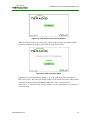
3.1.2
Logging into the MC
To log into the Management Console web interface:
1. From an Internet browser, enter the IP address of the MC web page. The IP address
may be a static or dynamic address, depending on how it is determined when the MC
is configured:
l Static IP Address: The IP address is hard-coded and must be known.
l Dynamic IP Address: The IP address is dynamically assigned by the Dynamic Host
Configuration Protocol (DHCP) server. You can get it from the DHCP server.
TER1206003 Issue 3
27
PCoIP® Zero Client and Host Administrator Guide
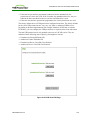
2. From the login page, enter the administrative password. The default value is blank
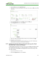
(i.e., "").
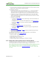
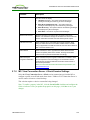
Figure 2-1: MC Login Page
3. When you first log into the MC, a prompt appears asking you to accept the license
agreement. After reading it, click Agree at this page. For subsequent logins, this
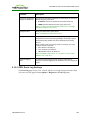
prompt does not appear.
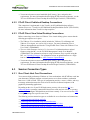
After logging into the MC, the Home page appears.
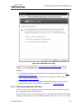
3.1.3
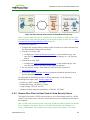
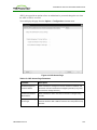
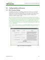
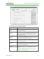
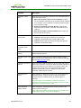
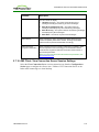
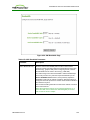
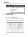
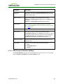
MC Home Page
The MC Home page contains links to all the MC functions, and also contains a Site Status
section that displays summary information about the PCoIP devices discovered by the MC.
TER1206003 Issue 3
28
PCoIP® Zero Client and Host Administrator Guide
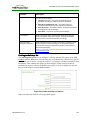
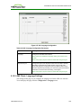
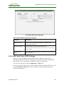
Figure 2-2: MC Home Page
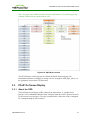
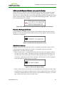
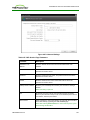
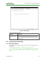
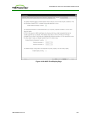
Device firmware is configured on the MC by defining profiles and then applying them to
groups of devices. Clicking the Profiles tab displays the Profile Management page, which
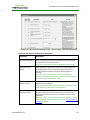
lists allows you to manage the profiles in your system.
3.1.4
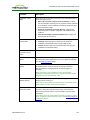
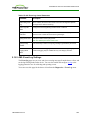
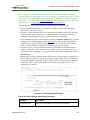
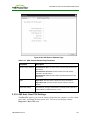
MC Profile Management Page
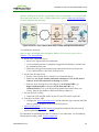
From the Profile Management page, you can view, add, duplicate, configure (i.e., set
properties for), edit, delete, and export profiles.
TER1206003 Issue 3
29
PCoIP® Zero Client and Host Administrator Guide
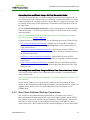
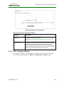
Figure 2-3: MC Profile Management Page
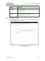
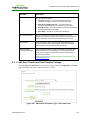
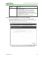
Once a profile has been created, you can click its Set Properties link to display the
Manage Profiles page and begin defining a device configuration for the profile.
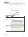
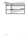
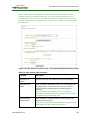
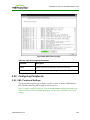
3.1.5
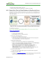
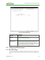
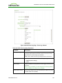
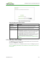
MC Manage Profiles Page
The figure below shows the Manage Profiles page for a profile. It contains a list of all the
categories used to configure the device firmware.
TER1206003 Issue 3
30
PCoIP® Zero Client and Host Administrator Guide
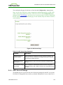
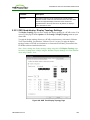
Figure 2-4: MC Manage Profiles Page
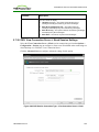
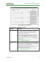
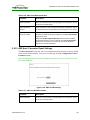
To configure a category, expand it and click the Edit Properties link, shown in the example
below.
Figure 2-5: Edit Properties Link
TER1206003 Issue 3
31
PCoIP® Zero Client and Host Administrator Guide
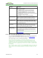
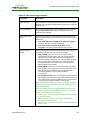
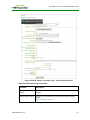
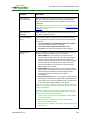
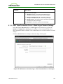
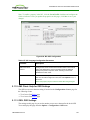
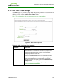
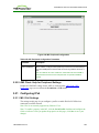
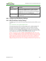
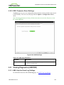
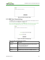
This displays the Set Properties page for that category, from which you can configure the
category's individual parameters. The following example shows the parameters for the
Network Configuration category.
Figure 2-6: Set Properties Page for Network Configuration
Note: The parameter table for each category has a Description column to explain each
parameter. These parameters are also explained in the MC sections of the GUI Reference.
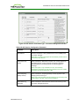
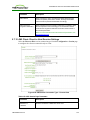
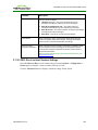
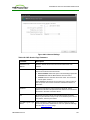
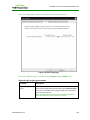
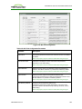
After setting the desired properties, the Manage Profiles page expands the categories to
show their configuration. You can use the expand/collapse links to control the display of this
information.
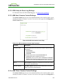
An example of a profile with some of its categories configured is shown below.
TER1206003 Issue 3
32
PCoIP® Zero Client and Host Administrator Guide
Figure 2-7: MC Manage Profiles Page – Configured
TER1206003 Issue 3
33
PCoIP® Zero Client and Host Administrator Guide
The GUI Reference in this help system contains full details about each category. For
information about how to configure or manage a device using these MC pages, please see
the appropriate section in the GUI Reference.
For details on how to apply a profile, please refer to the "PCoIP® Management Console
User Manual" (TER0812002).
3.2
PCoIP Administrative Web Interface
3.2.1
About the AWI
The PCoIP Administrative Web Interface (AWI) allows you to interact remotely with a
PCoIP host or client. From the AWI, you can manage and configure a host or client, view
important information about it, and even upload firmware and certificates to it.
After you type the device's IP address into an Internet Explorer or Mozilla Firefox browser,
the browser will use HTTPS (HTTP over an SSL socket) to connect to the device's AWI
web page. Access to the AWI is controlled using an administrative password, which can be
optionally disabled.
The AWI's HTTPS connection is secured using a PCoIP root Certificate Authority (CA)
certificate. To avoid warning messages when you log into the AWI, it is recommended that
you install this certificate in your browser. The certificate file ("cacert.pem") is always
included in a firmware release, but you can also download it directly from the Teradici
support site. For detailed instructions on how to install the certificate, see Knowledge Base
support topic 15134-529 on the Teradici support site.
The following browsers have been tested with this release:
l
l
3.2.2
Firefox version 3 or later
Internet Explorer 7.0 and 8.0
Logging into the AWI
To log into the Administrator Web Interface web page for a host or client:
1. From an Internet browser, enter the IP address of the host or client. The IP address
may be a static or dynamic address, depending on how the IP addresses are
determined within your IP network:
l Static IP Address: The IP address is hard-coded and must be known.
l Dynamic IP Address: The IP address is dynamically assigned by the Dynamic
Host Configuration Protocol (DHCP) server. You can get it from the DHCP server.
2. From the Log In page, enter the administrative password. The default value is blank
(i.e., "").
TER1206003 Issue 3
34
PCoIP® Zero Client and Host Administrator Guide
Figure 2-8: AWI Log In Page
3. To change idle timeout (the time after which the device is automatically logged off),
select an option from the Idle Timeout drop-down menu.
4. Click Log In.
Note: Some networks using DHCP may be able to access the AWI using the PCoIP device
name.
Note: Some PCoIP devices have password protection disabled and do not require a
password to log in. You can enable or disable password protection through the security
settings on the MC's Manage Profiles page.
If configured in the firmware defaults, the Initial Setup page appears the first time you log
in. You can configure audio, network, and session parameters on this page. After you click
Apply, the Home Page appears for each subsequent session. This page provides an
overview of the device status.
If a warning message appears when you try to log in, then a session is already in progress
on that device. Only one user can log into a device at one time. When a new session logs in,
the current session is ended and the previous user is returned to the Log In page.
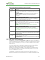
3.2.3
AWI Initial Setup Page
The AWI's Initial Setup page contains the audio, network, and session configuration
parameters that you must set before a client or host device can be used. This page helps to
simplify initial setup and reduce the time for new users to establish a session between a
PCoIP zero client and PCoIP host card in a remote workstation.
The AWI client Initial Setup and host Initial Setup pages are not identical. Each one
provides parameters that apply to the client and host, respectively.
If configured in the firmware defaults, the Initial Setup page appears the first time you log
in. After you click Apply, the Home page appears for subsequent sessions unless the
firmware parameters are reset.
Note: More complex environments that use host discovery or connection management
systems require further configuration than is available on the Initial Setup page.
TER1206003 Issue 3
35
PCoIP® Zero Client and Host Administrator Guide
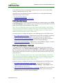
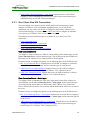
3.2.4
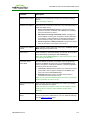
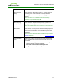
AWI Home Page
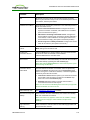
The AWI Home page displays a statistics summary for the host or client. You can display
the Home page at any time by clicking the Home link at the top left section of the menu bar.
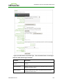
Figure 2-9: AWI Host: Home Page
TER1206003 Issue 3
36
PCoIP® Zero Client and Host Administrator Guide
Figure 2-10: AWI Client: Home Page
Note: The above figures show session statistics for devices that can support four connected
displays. If your deployment only supports two displays, information for these two displays
will appear in the bottom area of the page.
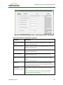
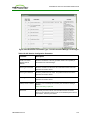
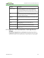
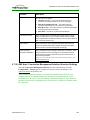
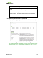
Table 2-1: AWI Home Page Statistics
Statistics
Description
Processor
PCoIP processor type, version, and RAM size
Time Since Boot
Length of time that the PCoIP processor has been running.
TER1206003 Issue 3
37
PCoIP® Zero Client and Host Administrator Guide
Statistics
Description
PCoIP Device Name
The logical name for the device.
This field is the name the host or client registers with the DNS server
if DHCP is enabled or the system is configured to support registering
the hostname with the DNS server. (See the PCoIP Device Name
parameter on the Label page.)
Connection State
The current (or last) state of the PCoIP session. Values include the
following:
l Asleep
l Canceling
l Connected
l Connection Pending
l Disconnected
l Waking
802.1X Authentication
Status
Indicates whether 802.1x authentication is enabled or disabled on
the device.
Session Encryption
Type
The type of encryption in use when a session is active:
l AES-128-GCM
l SALSA20-256-Round 12
PCoIP Packets Statistics
PCoIP Packets Sent: The total number of PCoIP packets sent in the
current/last session.
PCoIP Packets Received: The total number of PCoIP packets
received in the current/last session.
PCoIP Packets Lost: The total number of PCoIP packets lost in the
current/last session.
Bytes
Bytes Sent: The total number of bytes sent in the current/last
session.
Bytes Received: The total number of bytes received in the
current/last session.
Round Trip Latency
The minimum, average, and maximum round-trip PCoIP system and
network latency in milliseconds (+/- 1 ms).
Bandwidth Statistics
Transmit Bandwidth: The minimum, average, and maximum traffic
transmitted by the Tera processor. The active bandwidth limit is the
maximum amount of network traffic the Tera processor may currently
generate. The value is derived from the configured bandwidth
parameters and the current (or last) network congestion levels.
Receive Bandwidth: The minimum, average, and maximum traffic
received by the Tera processor.
Pipeline Processing
Rate
How much image data is currently being processed by the image
engine (in megapixels per second).
TER1206003 Issue 3
38
PCoIP® Zero Client and Host Administrator Guide
Statistics
Description
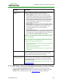
Endpoint Image Settings
In Use
Displays if the image settings being used are configured within the
client or within the host. This is based on how the Use Client Image
Settings field is configured on the Image page for the host device.
Image Quality
The minimum and maximum quality setting is taken from the Image
page for the device.
The active setting is what’s currently being used in the session and
only appears on the host.
Image Quality
Preference
This setting is taken from the Image Quality Preference field on the
Image page. The value determines if the image is set to a smoother
versus a sharper image.
Build to Lossless
Options that may appear in this field include the following:
Enabled: The Disable Build to Lossless field on the Image page is
unchecked.
Disabled: The Disable Build to Lossless field is checked.
Display
The port number for the display.
Maximum Rate
This column shows the refresh rate of the attached display.
If the Maximum Rate field on the Image page is set to 0 (i.e., there is
no limit), the maximum rate is taken from the monitor's refresh rate.
If the Maximum Rate field on the Image page is set to a value
greater than 0, the refresh rate shows as "User Defined."
Input Change Rate
The rate of content change from the GPU. This includes everything
the user is doing (such as cursor movement, email editing, or
streaming video).
Note: This option is only available on the host. It does not appear on
the client.
Output Process Rate
The frame rate currently being sent from the image engine on the
host to the client.
Image Quality
Shows the current lossless state of the attached display:
l Lossy
l Perceptually lossless
l Lossless
Note: When you click the Reset Statistics button on a host Session Statistics or client
Session Statistics page, the statistics reported in the Home page are also reset.
3.2.5
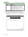
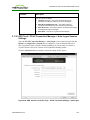
Failed Login Attempt Message
As of firmware release 4.1.0, a warning message alerts you if any failed access attempts to
the AWI, OSD, or MC were detected since the last successful login. The message provides
the date and time of the failed attempt, as shown below in the example warning message on
the AWI.
TER1206003 Issue 3
39
PCoIP® Zero Client and Host Administrator Guide
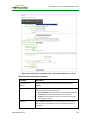
Figure 2-11: Failed Login Attempt Warning
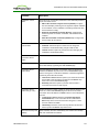
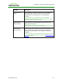
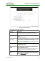
3.2.6
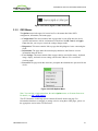
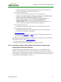
AWI Menus
The AWI has five main menus that link to the various configuration and status pages.
l
l
l
l
l
Configuration: The pages under this menu let you configure the various aspects for the
device, such as network settings, language, session parameters, etc.
Permissions: The pages under this menu let you set up the permissions for the USB,
audio, and power on the client, and for the USB and audio on the host.
Diagnostics: The pages under this menu help you troubleshoot the device.
Info: The pages listed this menu let you view firmware information and the devices
currently attached to the device.
Upload: The pages under this menu let you upload a new firmware version, an OSD
logo, and your certificates to the device.
The following figure shows the menus and pages available in the AWI.
TER1206003 Issue 3
40
PCoIP® Zero Client and Host Administrator Guide
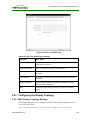
Note: The pages only available from the client are marked with a (*C) and the pages only
available from the host are marked with an (*H).
Figure 2-12: AWI Menu Overview
The GUI Reference in this help system contains full details about each page. For
information about how to configure or manage a device using these AWI pages, please see
the appropriate section in the GUI Reference.
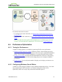
3.3
PCoIP On Screen Display
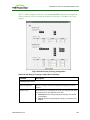
3.3.1
About the OSD
The PCoIP On Screen Display (OSD), shown in the figure below, is a graphical user
interface (GUI) embedded within the client. It displays when the client is powered on and a
PCoIP session is not in progress. The only exception to this is when the client is configured
for a managed startup or auto-reconnect.
TER1206003 Issue 3
41
PCoIP® Zero Client and Host Administrator Guide
Figure 2-13: OSD Main Window
An Options menu in the upper left-hand corner lets users access various sub-menus for
configuring the client and viewing information about it. A Connect button in the center of
the window lets users connect the client to a virtual desktop or to a host card in a remote
workstation.
3.3.2
Connecting to a Session
The OSD allows users to create a session between the client and a host card on a remote
workstation (or between the client and a virtual desktop) by clicking the green Connect
button in the center of the Connect window. Once the connection is established, the OSD
local GUI disappears, and the session image appears.
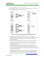
The following figure shows the Connect window for a Direct to Host session type—i.e.,
when the client is connecting to a host card in a remote workstation.
TER1206003 Issue 3
42
PCoIP® Zero Client and Host Administrator Guide
Figure 2-14: OSD Direct to Host Connect Window
While the network connection is initializing, various status messages are displayed above
the button to indicate the progress, such as the message shown below.
Figure 2-15: OSD Connection Status
If problems are experienced during startup—e.g., if the connection cannot be made or a
DHCP lease fails—other messages display in this area to indicate the nature of the problem.
The following figure shows the Connect window for a View Connection Server
connection—i.e., when the client is using a VMware View Connection Server to connect to
a virtual desktop.
TER1206003 Issue 3
43
PCoIP® Zero Client and Host Administrator Guide
Figure 2-16: OSD View Connection Server Connect Window
Note: you can change the logo that appears above the Connect button by uploading a
replacement image using the Upload > OSD Logo menu from a client's AWI.
While the connection is initializing, status messages may also display above the Connect
button to inform users of the connection progress or to alert them to a problem.
After connecting to the View Connection Server, the virtual desktop login page appears.
Figure 2-17: Virtual Desktop Login Page
If the user name and password are not entered correctly, or if the Caps Lock key is on, a
message displays on this page to indicate these problems.
If the correct trusted SSL root certificate for the VMware View Connection Server has not
been installed in the client, the following warning appears.
TER1206003 Issue 3
44
PCoIP® Zero Client and Host Administrator Guide
Figure 2-18: OSD View Connection Server Certificate Warning
If the user clicks Continue at this warning, the session will not be secure. This is indicated
by the warning icon on the lock in the upper left of the window and also by the red "https"
with strikethrough formatting, which tells users that the secure HTTPS protocol will not be
used for the connection.
Figure 2-19: OSD Login Screen with Insecure Warning
As an administrator, you can use the Options > User Settings > VMware View page,
shown below, to prevent users from initiating insecure sessions by configuring the zero
client to refuse a connection to a server that cannot be verified.
TER1206003 Issue 3
45
PCoIP® Zero Client and Host Administrator Guide
Figure 2-20: OSD VMware View Page
Using the AWI, you can then enable VCS Certificate Check Mode Lockout from the
Session – View Connection Server page to prevent users from changing this setting.
See also:
l
l
l
3.3.3
For information about how to upload certificates to a profile using the MC, see MC:
Certificate Store Management.
For information on how to upload certificates to a single device using the AWI, see
AWI: Certificate Upload Settings.
For information on other OSD messages that may appear on top of a user's session
during startup or after a session has been established, see Overlay Windows.
Disconnecting from a Session
For Tera1 clients, users can disconnect from a session and return to the OSD by pressing
the connect/disconnect button on the device.
For Tera2 clients, users can also disconnect from a virtual desktop session and return to the
OSD by pressing the device's connect/disconnect button. However, if a user is in a session
TER1206003 Issue 3
46
PCoIP® Zero Client and Host Administrator Guide
with a host card in a remote workstation, pressing this button will pop up the Zero Client
Control Panel overlay, shown in the figure below, which provides options to disconnect from
the session, to power off the remote workstation, or to cancel the operation.
Figure 2-21: Zero Client Control Panel
Users can select an option from this overlay in a number of ways:
l
l
l
Continue to tap the connect/disconnect button to toggle between options until the desired
one is highlighted, then wait for the four-second countdown to complete.
Use the up/down arrow keys on the keyboard to highlight the desired option, then press
the Enter key.
Type the number of the desired option to select it immediately.
During a session, users can also use a Ctrl+Alt+F12 hotkey sequence to display this overlay,
providing the following options are configured in advance:
l
l
l
Enable Session Disconnect Hotkey must be enabled in the advanced options on the
Session – View Connection Server page.
The Enable Local Cursor and Keyboard feature must be enabled on the PCoIP host
software on the host computer. For details, see "PCoIP® Host Software for Windows
User Guide" (TER1008001).
On the client, the keyboard must be recognized as locally connected (i.e., not bridged).
Note: the latter two options must also be in place in order for users to use the up/down
arrow keys or to type in a number to select a disconnect option on this overlay.
In order to allow users to use the second overlay option (i.e., to power off the workstation),
the power permissions on the client must be configured to allow a "hard" power off. You
can set this parameter from the MC Power Permissions page or from the AWI Power
Permissions page.
3.3.4
Overlay Windows
Overlay windows occasionally appear on top of the user's PCoIP session to display pertinent
information when the status changes—e.g., when the network connection is lost or an
TER1206003 Issue 3
47
PCoIP® Zero Client and Host Administrator Guide
unauthorized USB device is plugged in. These overlays show network, USB device, and
monitor statuses as icons and text, as shown in the examples below.
Display Link Training Failed
This overlay only displays on Tera2 clients that contain DisplayPort display interfaces (as
opposed to DVI interfaces). The DisplayPort protocol requires a link training sequence for
adapting to differing cable lengths and signal qualities. If this training does not succeed, the
following overlay appears with the message "Display link training failed."
Figure 2-22: Display Link Training Failed Overlay
Half Duplex Overlay
PCoIP technology is not compatible with half-duplex network connections. When a halfduplex connection is detected, the following overlay appears with the message "Half-duplex
network connection."
Figure 2-23: Half Duplex Overlay
Network Connection Lost Overlay
Loss of network connectivity is indicated using an overlay with the message "Network
connection lost" over the most recent screen data. This overlay appears when the client
network cable is disconnected or when no PCoIP protocol traffic is received by the client
for more than two seconds.
Figure 2-24: Network Connection Lost Overlay
The lost network connection message appears until the network is restored or the timeout
expires (and the PCoIP session ends).
Note: It is not recommended to use this notification message when using PCoIP devices
with virtual desktops. Normal scheduling within the virtual desktop hypervisor can falsely
trigger this message. To prevent this problem, you can disable the Enable Peer Loss
Overlay setting.
TER1206003 Issue 3
48
PCoIP® Zero Client and Host Administrator Guide
No Support Resolutions Found
This overlay displays on Tera2 clients only. Display resolution may have limitations due to
resource constraints when all four ports have large displays connected. If the resolution limit
is exceeded, the following overlay appears with the message "No support resolutions found.
Please try unplugging other displays."
Figure 2-25: No Support Resolutions Found Overlay
Preparing Desktop Overlay
When a user first logs into a PCoIP session, the following overlay appears with the message
"Preparing desktop."
Figure 2-26: Preparing Desktop Overlay
USB Device Not Authorized Overlay
If an unauthorized USB device is connected, the following overlay appears with the
message "USB device not authorized." This overlay lasts for approximately five seconds.
Figure 2-27: USB Device Not Authorized Overlay
USB Over Current Notice Overlay
If the USB devices connected to the client cannot be handled by the USB ports, the
following overlay appears with the message "USB over current notice." This overlay
remains until USB devices are removed to meet the current handling of the USB ports.
Figure 2-28: USB Over Current Notice Overlay
TER1206003 Issue 3
49
PCoIP® Zero Client and Host Administrator Guide
USB Device Not Supported Behind a High-speed Hub Overlay
Some USB devices cannot be connected through a high speed (USB 2.0) hub, and should
instead be connected directly to the zero client or through a full speed (USB 1.1) hub. If
such a device is connected to the zero client through a high speed hub, the following overlay
appears with the message "USB device not supported behind high speed hub." This overlay
lasts for approximately five seconds.
Figure 2-29: USB Device Not Supported Behind a High-speed Hub Overlay
Resolution Not Supported Overlay
If the resolution of a monitor connected to the client cannot be supported by the host, the
monitor is set to its default resolution and the following overlay appears with the message
"Resolution not supported."
Figure 2-30: Resolution Not Supported Overlay
Video Source Overlays
Improper connection of the host video source is denoted by two possible overlays. These
overlays appear for approximately five minutes. The monitor is put into sleep mode
approximately 15 seconds after they appear.
l
When no video source is connected to the host, the following overlay appears with the
message "No source signal." This helps you debug a situation where the host does not
have the video source connected or the host PC has stopped driving a video signal. To
correct this, connect the host PC video to the host. (This message can also be triggered
by the host going into display power save mode.)
Figure 2-31: No Source Signal Overlay
l
When a video source to the host does not correspond to the video port used on the client,
the following overlay appears with the message "Source signal on other port." This helps
you debug a situation where the video source is connected to the wrong port. To correct
this, swap the video ports at the host or the client.
TER1206003 Issue 3
50
PCoIP® Zero Client and Host Administrator Guide
Figure 2-32: Source Signal on Other Port Overlay
3.3.5
OSD Menus
The Options menu in the upper left corner has five sub-menus that link to OSD
configuration, information, and status pages.
l
l
l
l
l
Configuration: This menu contains links to pages that let you define how the device
operates and interacts with its environment. Each tab has an OK, Cancel, and Apply
button that lets you accept or cancel the settings changes made.
Diagnostics: This menu contains links to pages that help diagnose issues concerning the
client.
Information: The page under this menu displays hardware and firmware version
information about the device.
User Settings: This menu contains links to pages that let users define mouse, keyboard,
image, display, and touch screen settings, and also the VMware View certificate
checking mode.
Password: The page under this menu lets you update the administrative password for the
device.
Figure 2-33: OSD Options Menu
Note: You can hide a single menu item, the entire Options menu, or all menus from users.
For details, see MC: OSD Settings.
The GUI Reference in this help system contains full details about each page. For
information about how to configure or manage a device using these OSD pages, please see
the appropriate section in the GUI Reference.
TER1206003 Issue 3
51
PCoIP® Zero Client and Host Administrator Guide
4
PCoIP Deployment Scenarios
4.1
PCoIP Endpoints
PCoIP is a flexible technology that lets you deploy both PCoIP hardware endpoints (e.g.,
PCoIP zero clients and host cards) and PCoIP software endpoints (e.g., soft clients and
virtual desktops) in your network. For example, you can use a zero client to connect to a
PCoIP host card or to a virtual desktop. Alternatively, you can use a PCoIP soft client to
connect to a host card or virtual desktop.
4.1.1
PCoIP Hardware Endpoints
The following figure shows some examples of PCoIP hardware endpoints that you can
deploy in your network.
Figure 3-1: PCoIP Hardware Endpoints
The table below lists the processor name and family for each device, along with the set of
display resolutions the device supports.
Note: The processor name refers to the chipset used in the PCoIP device. For example,
TERA2140 is the processor used in the second-generation TERA2140 zero client, and
TERA2240 is the processor used in the second-generation TERA2240 PCIe host card (for
tower PC or rack mount workstations) and TERA2240 PCI Mezzanine host card (for blade
workstations). For details on how to display the processor name for your device, see
Displaying Processor Information.
TER1206003 Issue 3
52
PCoIP® Zero Client and Host Administrator Guide
Table 3-1: Supported Resolutions for PCoIP Host Cards and Zero Clients
Processor
Name
Maximum No. of Supported
Displays and Resolutions
Device Type
Processor Family
TERA1100
2 x 1920x1200
zero client
Tera1
TERA2321
2 x 1920x1200
1 x 2560x1600*
zero client
Tera2
TERA2140
4 x 1920x1200
2 x 2560x1600*
zero client
Tera2
TERA1202
2 x 1920x1200
host card
Tera1
TERA2220
2 x 1920x1200
1 x 2560x1600
host card
Tera2
TERA2240
4 x 1920x1200
2 x 2560x1600
host card
Tera2
*Tera2 zero clients support 2560x1600 resolution on attached displays using either DVI or
DisplayPort interfaces. For instructions on how to connect cables to Tera2 zero clients with
DVI and/or DisplayPort ports to support this resolution, see DVI and DisplayPort Interfaces.
You can mix and match any host card with any zero client. However, when you connect a
zero client to a host card, the maximum supported resolutions for any displays attached to
the client will equal the most common denominator between the two devices. For example,
if you connect a TERA2140 zero client to a TERA2240 host card, you can attach up to four
1920x1200 displays or two 2560x1600 displays. However, if you connect a TERA2321 zero
client to the same host card, the options become up to two 1920x1200 displays or one
2560x1600 display.
4.1.2
PCoIP Software Endpoints
A number of software endpoints also support PCoIP, such as the following:
l
l
l
l
Teradici PCoIP software clients: PCoIP software clients that have been developed by
Teradici.
VMware View clients and VDI desktops: PCoIP desktop virtualization products
developed by VMware.
Teradici Arch published desktop solution: Published desktops that use PCoIP as the
remote protocol instead of RDP.
PCoIP optimized clients: Software clients that have been optimized to take advantage
of thin client platforms, including system on chip (SoC) processors. These clients are
developed individually for specific client platforms in order to deliver the best possible
combination of features and performance.
Some examples of PCoIP software endpoints are illustrated in the figure below.
TER1206003 Issue 3
53
PCoIP® Zero Client and Host Administrator Guide
Figure 3-2: PCoIP Software Endpoints
4.2
Connection Prerequisites
4.2.1
PCoIP Client–Host Card Connections
Before connecting a host card and zero client, please ensure that the following prerequisites
are in place:
l
l
l
The host card and zero client have the same firmware versions. For information how to
upload firmware using the MC, see the "PCoIP® Management Console User Manual"
(TER0812002). For information on how to assign a firmware file to a profile using the
MC, see Uploading Firmware. For information on how to upload firmware to a single
host or client using the AWI, see AWI: Firmware Upload Settings.
The PCoIP host software is installed on the host PC or workstation. For details, please
see "PCoIP® Host Software for Windows User Guide" (TER1008001). If you are using
VMware View as a broker, View Agent must also be installed on the host PC or
workstation.
The Host Driver Function is enabled on the host card.
TER1206003 Issue 3
54
PCoIP® Zero Client and Host Administrator Guide
l
4.2.2
Your network resources meet bandwidth, QoS, latency, jitter, and packet loss
requirements. For more information about designing PCoIP network architecture, see the
"PC-over-IP® Protocol Virtual Desktop Network Design Checklist" (TER1105004).
PCoIP Client–Published Desktop Connections
This connection is implemented via the Teradici Arch™ published desktop software
solution. Please see "Teradici Arch™ Published Desktop Installation Guide" (TER1211001)
for more information about Teradici Arch prerequisites.
4.2.3
PCoIP Client–View Virtual Desktop Connections
Before connecting a zero client to a VMware View virtual desktop, please ensure that the
following prerequisites are in place:
l
l
l
The VMware View installation, which includes the VMware View Manager and
VMware View Agent, are version 4.0.1 or newer. For more information, refer to
VMware documentation and also the "Using PCoIP® Zero Clients with VMware View
User Guide" (TER0904005).
The zero client firmware version is 3.1.0 or newer. For information how to upload
firmware using the MC, see the "PCoIP® Management Console User Manual"
(TER0812002). For information on how to assign a firmware file to a profile using the
MC, see Uploading Firmware. For information on how to upload firmware to a single
host or client using the AWI, see AWI: Firmware Upload Settings.
Your network resources meet bandwidth, QoS, latency, jitter, and packet loss
requirements. For more information about designing PCoIP network architecture, see the
"PC-over-IP® Protocol Virtual Desktop Network Design Checklist" (TER1105004).
4.3
Session Connection Types
4.3.1
Zero Client–Host Card Connections
You can move high-performance Windows or Linux workstations with PCoIP host cards into
your datacenter, and then configure sessions between zero clients and these workstation
hosts over a LAN or WAN. This type of configuration provides a secure, reliable, and easyto-manage solution that meets the needs of users who have dedicated computers with
graphically demanding applications.
Depending on the size of your PCoIP deployment, you may wish to use the MC or a
connection broker to manage connections between host cards and zero clients, or you may
use the AWI to configure individual hosts and clients remotely. You can even use the OSD
to configure settings for a specific zero client.
The following session connection types are available for zero client–host card connections:
l
l
l
l
Connecting hosts and clients statically
Connecting hosts and clients using SLP host discovery
Connecting hosts and clients using a 3rd party connection broker
Connecting hosts and clients using the VMware View Connection Server broker
TER1206003 Issue 3
55
PCoIP® Zero Client and Host Administrator Guide
Connecting Hosts and Clients Statically
To statically configure a client to connect directly to a specific host card, use the Direct to
Host session connection type. You need to provide the IP address (or DNS name) of the
host for this option.
You also need to configure a Direct from Client session connection type on the host. You
have the option of allowing the host to accept a connection request from any client or from a
specific client only. If the latter, you need to provide the client's MAC address.
For details on how to configure this option, see the following topics in the GUI Reference:
l
l
l
l
MC: Direct to Host: Explains how to use the MC to configure a profile that sets the
Direct to Host session connection type for client devices. For information on how to
statically link specific hosts and clients using the MC, see the "PCoIP® Management
Console User Manual" (TER0812002).
AWI Client: Direct to Host: Explains how to use the AWI to statically configure a client
to connect to a specific host card.
AWI Host: Direct from Client: Explains how to use the AWI to configure a host card to
accept a connection request from any client or from a specific client only.
OSD: Direct to Host: Explains how to use the OSD to statically configure a client to
connect to a specific host card.
Connecting Hosts and Clients Using SLP Host Discovery
If hosts reside on the same subnet as clients, you can use the Direct to Host + SLP session
connection type to configure clients to use Service Location Protocol (SLP) to discover the
hosts on the subnet. With this configuration, the client OSD will list the first 10 hosts
discovered. The user can then select the desired one and connect to it.
Note: SLP host discovery is not suitable for deployments with more than 10 hosts if a client
needs to connect to a specific host all the time. In this situation, a 3rd party connection
broker is required.
You also need to configure a Direct from Client session connection type on the host. You
have the option of allowing the host to accept a connection request from any client or from a
specific one only. If the latter, you need to provide the client's MAC address.
For details on how to configure this option, see the following topics in the GUI Reference:
l
l
l
l
MC: Direct to Host + SLP: Explains how to use the MC to configure a profile that sets
the Direct to Host + SLP session connection type for client devices.
AWI Client: Direct to Host + SLP: Explains how to use the AWI to configure a client to
use SLP discovery to connect to a host card.
AWI Host: Direct from Client: Explains how to use the AWI to configure a host card to
accept a connection request from any client or from a specific client only.
OSD: Direct to Host + SLP: Explains how to use the OSD to configure a client to use
SLP discovery to connect to a host card.
TER1206003 Issue 3
56
PCoIP® Zero Client and Host Administrator Guide
Connecting Hosts and Clients Using a 3rd Party Connection Broker
A 3rd party connection broker is a resource manager that dynamically assigns host PCs to
zero clients based on the identity of the user establishing a connection from the zero client.
Connection brokers are also used to allocate a pool of hosts to a group of zero clients. They
are typically used in large PCoIP deployments, or when hosts and clients do not reside on
the same subnet.
Use the Connection Management Interface session connection type on both the host and
client for this option. You need to provide the IP address (or DNS name) for the 3rd party
connection broker.
Note: For information about 3rd party connection brokers, see Knowledge Base support
topic 15134-24 on the Teradici support site.
For details on how to configure this option, see the following topics in the GUI Reference:
l
l
l
l
MC: Connection Management Interface: Explains how to use the MC to configure a
profile that sets the Connection Management Interface session connection type for
client and host devices.
AWI Client: Connection Management Interface: Explains how to use the AWI to
configure a client to use a 3rd party connection broker to broker the connection between
the client and a host card.
AWI Host: Connection Management Interface: Explains how to use the AWI to
configure a host to use a 3rd party connection broker for accepting a connection request
from a client.
OSD: Connection Management Interface: Explains how to use the OSD to configure a
client to use a 3rd party connection broker to broker the connection between the client
and a host card.
Connecting Hosts and Clients Using the VMware View Connection Server Broker
You can also use the VMware View Connection Server to broker a connection between
clients and host cards.
Note: This is not the same thing as configuring a zero client to connect to a VMware View
virtual desktop.
For this option, VMware View Agent must be installed on the host workstation, and a
number of other configuration requirements for both the client and host must be in place. For
complete details, please refer to "Using PCoIP® Host Cards with VMware View"
(TER0911004).
4.3.2
Zero Client–Published Desktop Connections
The Teradici Arch™ published desktop solution allows you connect zero clients to
Microsoft published desktops using PCoIP as the remote display protocol instead of RDP.
This solution is brokered by a PCoIP Connection Manager virtual appliance, which can be
installed in a corporate LAN to connect internal clients and/or in the DMZ to connect
remote clients over a WAN. When the PCoIP Connection Manager is located in the DMZ,
TER1206003 Issue 3
57
PCoIP® Zero Client and Host Administrator Guide
its PCoIP Security Gateway component is enabled to allow users access to their remote
desktops without having to set up a VPN.
The following session connection types are available for zero client–published desktop
connections using Teradici Arch™:
l
l
PCoIP Connection Manager
PCoIP Connection Manager + Auto-Logon
PCoIP Connection Manager
To configure a client to connect to a published desktop with a manual logon, use the PCoIP
Connection Manager session connection type. You need to provide the IP address (or DNS
name) of the PCoIP Connection Manager for this option.
Note: The server DNS name must resolve to the external WAN IP address of the PCoIP
Security Gateway in the DMZ for external connections, and to the IP address of the PCoIP
Connection Manager for internal connections. For details, please see "Teradici Arch™
Published Desktop Installation Guide" (TER1211001)
For details on how to configure this option, see the following topics in the GUI Reference:
l
l
l
MC: PCoIP Connection Manager: Explains how to use the MC to configure a profile that
sets the PCoIP Connection Manager session connection type for client devices.
AWI Client: PCoIP Connection Manager: Explains how to use the AWI to configure a
client to connect to a published desktop via a PCoIP Connection Manager.
OSD: PCoIP Connection Manager: Explains how to use the OSD to configure a client to
connect to a published desktop via a PCoIP Connection Manager.
PCoIP Connection Manager + Auto-Logon
To configure clients to automatically enter users' login details when clients connect to a
published desktop, use the PCoIP Connection Manager + Auto-Logon session connection
type. You need to provide the IP address (or DNS name) of the PCoIP Connection Manager
for this option, and also the user name, user password, and the domain name for the user to
send to the server.
Note: The server DNS name must resolve to the external WAN IP address of the PCoIP
Security Gateway in the DMZ for external connections, and to the IP address of the PCoIP
Connection Manager for internal connections. For details, please see "Teradici Arch™
Published Desktop Installation Guide" (TER1211001)
For details on how to configure this option, see the following topics in the GUI Reference:
l
l
MC: PCoIP Connection Manager + Auto-Logon: Explains how to use the MC to
configure a profile that sets the PCoIP Connection Manager + Auto-Logon session
connection type for client devices.
AWI Client: PCoIP Connection Manager + Auto-Logon: Explains how to use the AWI to
configure a client to automatically enter the user's login details when connecting to a
published desktop via a PCoIP Connection Manager.
TER1206003 Issue 3
58
PCoIP® Zero Client and Host Administrator Guide
l
4.3.3
OSD: PCoIP Connection Manager + Auto-Logon: Explains how to use the OSD to
configure a client to automatically enter the user's login details when connecting to a
published desktop via a PCoIP Connection Manager.
Zero Client–View VDI Connections
You can configure zero clients to use the PCoIP protocol when connecting to virtual
desktops in a VMware View environment. Depending on the size of your PCoIP
deployment, you may wish to use the MC to configure a profile with a VMware View
session connection type, or you may use the AWI or the OSD to configure an individual
zero client to use a VMware View session connection type.
The following session connection types are available for zero client–View VDI
connections:
l
l
l
l
View
View
View
View
Connection Server
Connection Server + Auto-Logon
Connection Server + Kiosk
Connection Server + Imprivata OneSign
View Connection Server
To configure a client to connect to a VMware virtual desktop with a manual logon, use the
View Connection Server session connection type. You need to provide the IP address (or
DNS name) of the VMware View Connection Server for this option.
For details on how to configure this option, see the following topics in the GUI Reference:
l
l
l
MC: View Connection Server: Explains how to use the MC to configure a profile that
sets the View Connection Server session connection type for client devices.
AWI Client: View Connection Server: Explains how to use the AWI to configure a
client to connect to a virtual desktop via a VMware View Connection Server.
OSD: View Connection Server: Explains how to use the OSD to configure a client to
connect to a virtual desktop via a VMware View Connection Server.
View Connection Server + Auto-Logon
To configure clients to automatically enter users' login details when clients connect to a
virtual desktop, use the View Connection Server + Auto-Logon session connection type.
You need to provide the IP address (or DNS name) of the VMware View Connection
Server, and also the user name, user password, and the domain name for the user to send to
the server.
For details on how to configure this option, see the following topics in the GUI Reference:
l
l
MC: View Connection Server + Auto-Logon: Explains how to use the MC to configure a
profile that sets the View Connection Server + Auto-Logon session connection type for
client devices.
AWI Client: View Connection Server + Auto-Logon: Explains how to use the AWI to
configure a client to automatically enter the user's login details when connecting to a
virtual desktop via a VMware View Connection Server.
TER1206003 Issue 3
59
PCoIP® Zero Client and Host Administrator Guide
l
OSD: View Connection Server + Auto-Logon: Explains how to use the OSD to configure
a client to automatically enter the user's login details when connecting to a virtual
desktop via a VMware View Connection Server.
View Connection Server + Kiosk
VMware View Kiosk mode allows you to configure clients to connect to a desktop that will
be used for a kiosk implementation, such as when multiple users connect to a desktop to
obtain information that is not specific to any one individual. At minimum, you need to
provide the IP address (or DNS name) of the VMware View Connection Server and the
kiosk user name—either a custom user name for the kiosk or its MAC address.
For details on how to configure this option, see the following topics in the GUI Reference:
l
l
l
MC: View Connection Server + Kiosk: Explains how to use the MC to configure a
profile that sets the View Connection Server + Kiosk session connection type for client
devices.
AWI Client: View Connection Server + Kiosk: Explains how to use the AWI to
configure a client to use Kiosk mode when connecting to a virtual desktop via a VMware
View Connection Server.
OSD: View Connection Server + Kiosk: Explains how to use the OSD to configure a
client to use Kiosk mode when connecting to a virtual desktop via a VMware View
Connection Server.
View Connection Server + Imprivata OneSign
VMware View Imprivata OneSign mode allows you to configure clients to use Imprivata
OneSign proximity card support when connecting to a virtual desktop via a VMware View
Connection Server. You need to provide the IP address (or DNS name) of the VMware
View Connection Server and the bootstrap URL for the OneSign server.
For details on how to configure this option, see the following topics in the GUI Reference:
l
l
l
MC: View Connection Server + Imprivata OneSign: Explains how to use the MC to
configure a profile that sets the View Connection Server + Imprivata OneSign session
connection type for client devices.
AWI Client: View Connection Server + Imprivata OneSign: Explains how to use the
AWI to configure a client to use Imprivata OneSign mode when connecting to a virtual
desktop via a VMware View Connection Server.
OSD: View Connection Server + Imprivata OneSign: Explains how to use the OSD to
configure a client to use Imprivata OneSign mode when connecting to a virtual desktop
via a VMware View Connection Server.
4.4
Common LAN Scenarios
4.4.1
Connecting over a LAN
LAN connections between PCoIP endpoints can either be direct or brokered by a connection
server. The scenarios listed below describe some of the most common ways you can
connect PCoIP endpoints over a LAN.
TER1206003 Issue 3
60
PCoIP® Zero Client and Host Administrator Guide
l
l
l
Scenario 1: Connecting a zero client to a host card.
Scenario 2: Using a View Connection Server to broker a connection between a zero
client to a host card.
Scenario 3: Using a View Connection Server to broker a connection between a zero
client to a virtual desktop.
Note: You can also use the Teradici Arch™ published desktop solution to connect a PCoIP
client to a Microsoft published desktop using PCoIP as the remote protocol. For details,
please see "Teradici Arch™ Published Desktop Installation Guide" (TER1211001).
4.4.2
Zero Client to Host Card
The figure below shows a PCoIP session between a zero client and host card from within a
LAN.
Note: All host card scenarios assume you have the PCoIP host software installed on the host
PC or workstation. For details, please see "PCoIP® Host Software for Windows User
Guide" (TER1008001). Please refer to Connection Prerequisites for other conditions that
may apply.
Figure 3-3: Zero Client to Host Card (LAN)
To establish the connection:
1. From the zero client's AWI:
l Configure the Direct to Host session connection type, and enter the DNS name or
IP address of the host card.
2. From the host card's AWI:
l Configure the Direct from Client session connection type, and whether to accept
any peer (i.e., zero client) or a specific one.
3. Start a PCoIP session.
4. If necessary, adjust bandwidth and image parameters on both the host and client to
optimize performance.
4.4.3
Zero Client to Host Card via View Connection Server
The figure below shows a PCoIP session between a zero client and host card from within a
LAN using a View Connection Server to connect the endpoints.
TER1206003 Issue 3
61
PCoIP® Zero Client and Host Administrator Guide
Note: All host card scenarios assume you have the PCoIP host software installed on the host
PC or workstation. For details, please see "PCoIP® Host Software for Windows User
Guide" (TER1008001). This scenario also assumes you have the VMware View Agent
software installed on the host PC or workstation. For more information, see "Using PCoIP®
Host Cards with VMware View" (TER0911004). Please refer to Connection Prerequisites
for other conditions that may apply.
Figure 3-4: View – Zero Client to Host Card via View Connection Server
To establish the connection:
Note: For more information about configuring VMware View servers, please refer to
VMware View documentation.
1. From the View Connection Server:
l Install View Agent on the host workstation.
l Create a manual pool that is configured to support PCoIP hardware, and then add
the workstation to the pool.
l Ensure that the Use Secure Tunnel connection to desktop checkbox is enabled.
(This checkbox is enabled by default.)
l Enter the View Connection Server's IP address or domain name for the External
URL (e.g. 192.168.1.140:443 or https://myserver.com:443).
2. From the zero client's AWI:
l Configure the View Connection Server session connection type, and enter the DNS
name or IP address of the View Connection Server.
3. Start a PCoIP session.
4.4.4
Zero Client to Virtual Desktop via View Connection Server
The figure below shows a PCoIP session between a zero client and a virtual desktop from
within a LAN using a View Connection Server to connect the endpoints.
TER1206003 Issue 3
62
PCoIP® Zero Client and Host Administrator Guide
Figure 3-5: View – Zero Client to Virtual Desktop via View Connection Server
To establish the connection:
Note: For more information about configuring VMware View servers, please refer to
VMware View documentation.
1. On the ESXi server:
l Create a virtual machine (VM).
l Install Windows and View Agent on the VM.
2. On the View Connection Server:
l Create a pool, and add the VM to the pool.
l Ensure that the Use Secure Tunnel connection to desktop checkbox is enabled.
(This checkbox is enabled by default.)
l Enter the View Connection Server's IP address or domain name for the External
URL (e.g. 192.168.1.140:443 or https://myserver.com:443).
3. From the zero client's AWI:
l Configure the View Connection Server session connection type, and enter the DNS
name or IP address of the View Connection Server.
4. Start a PCoIP session.
For information on optimizing networks for VMware View connections, see the following
Knowledge Base topics on the Teradici support site:
l
l
PCoIP session variable settings: 15134-276
Windows desktop experience optimization: 15134-242, 15134-880
4.5
Common Remote Access Scenarios
4.5.1
Connecting Remotely
PCoIP sessions between clients and hosts can operate in a wide area network (WAN) that
traverses the Internet. You can connect clients and hosts remotely using the following main
methods:
l
Configuring network address translation (NAT) devices at both ends to implement the
necessary IP address and port translation. This method applies only to Tera2 devices that
TER1206003 Issue 3
63
PCoIP® Zero Client and Host Administrator Guide
l
l
employ UDP-encapsulated IPsec ESP encryption (firmware 4.1.0 or later).
Setting up a VPN to connect two trusted networks over an intermediate untrusted
network.
Using a security server/connection server pair to secure and broker the outside client to
the trusted inside network.
The scenarios listed below describe some common ways you can connect PCoIP endpoints
remotely.
l
l
l
l
l
l
l
Scenario 1: Connecting a remote zero client to a host card.
Scenario 2: Connecting a remote zero client to a host card over a hardware VPN.
Scenario 3: Using a third-party broker to connect a remote zero client to a host card.
Scenario 4: Using a View Security Server/View Connection Server pair to broker a
connection between a remote zero client and a host card.
Scenario 5: Using a View Security Server/View Connection Server pair to broker a
connection between a zero client and a View virtual desktop.
Scenario 6: Using a View Security Server/View Connection Server pair to broker a
connection between a remote View software client and a host card.
Scenario 7: Using View Connection Servers for remote and internal connections.
Note: You can also use the Teradici Arch™ published desktop solution over a WAN to
connect a PCoIP client to a Microsoft published desktop using PCoIP as the remote protocol.
For details, please see "Teradici Arch™ Published Desktop Installation Guide"
(TER1211001).
4.5.2
Remote Zero Client to Host Card
As of firmware 4.1.0, Tera2 zero clients and host cards use UDP-encapsulated IPsec
format. Because this encapsulation type supports IP address and port number translation, it
is not necessary to set up a VPN when these devices connect remotely. To connect devices
with earlier firmware versions, see Zero Client to Host Card Using a Hardware VPN.
Note: All host card scenarios assume you have the PCoIP host software installed on the host
PC or workstation. For details, please see "PCoIP® Host Software for Windows User
Guide" (TER1008001). Please refer to Connection Prerequisites for other conditions that
may apply.
Note: The IP addresses in the following figures are intended as example addresses only.
The figure below shows a PCoIP session between a Tera2 zero client and host card over a
WAN.
TER1206003 Issue 3
64
PCoIP® Zero Client and Host Administrator Guide
Figure 3-6: Tera2 Zero Client to Host Card (WAN)
You can also have multiple zero clients and host cards connected behind NAT devices, as
shown in the next figure.
Note: In this scenario, an enterprise-level NAT device is required in both the source and
destination networks.
Figure 3-7: Remote PCoIP Sessions with Multiple Tera2 Devices
To establish the connection:
1. For the first scenario: Configure the enterprise NAT device to redirect TCP/UDP port
4172 to the host card.
For the second scenario:
l Configure the source enterprise NAT device (203.0.0.1) to translate IP address and
ports as follows:
192.168.0.1:4172 to 203.0.0.1:4172
192.168.0.2:4172 to 203.0.0.1:4173
192.168.0.3:4172 to 203.0.0.1:4174
TER1206003 Issue 3
65
PCoIP® Zero Client and Host Administrator Guide
Configure the destination enterprise NAT device (144.0.0.1) to translate IP
addresses and ports as follows:
144.0.0.1:4172 to 10.0.10.1:4172
144.0.0.1:4173 to 10.0.10.2:4172
144.0.0.1:4174 to 10.0.10.3:4172
From the zero client's AWI:
l Configure the Direct to Host session connection type, and enter the IP address of
the destination enterprise NAT device.
From the host card's AWI:
l Configure the Direct from Client session connection type.
On your firewall or router, allow both TCP and UDP traffic on the ports you have
configured in your NAT devices (4172+).
Start a PCoIP session.
If necessary, adjust bandwidth and image parameters on both the host and client to
optimize performance.
l
2.
3.
4.
5.
6.
For more information on how NAT applications work with PCoIP, see Knowledge Base
support topic 15134-830 on the Teradici support site. For information on optimizing networks
for WAN connections, see the following Knowledge Base topics:
l
l
l
l
4.5.3
Packet size (MTU) settings: 15134-40
Bandwidth settings: 15134-242, 15134-88
Image settings: 15134-28, 15134-51
Windows desktop experience optimization: 15134-242, 15134-880
Remote Zero Client to Host Card via Hardware VPN
The figure below shows a PCoIP session between a remote zero client and host card over a
hardware VPN.
Figure 3-8: Hardware VPN – Zero Client to Host Card
A VPN is necessary when connecting the following PCoIP endpoints over the Internet:
l
l
Tera1 zero client to a Tera1 host card
Tera2 zero client to a Tera2 host card when the installed firmware in these devices is
prior to release 4.1.0
TER1206003 Issue 3
66
PCoIP® Zero Client and Host Administrator Guide
l
Tera2 zero client to a Tera2 host card when the enterprise NAT device/gateway cannot
implement the required IP address and port translation
To establish the connection:
1. At the home network, install a VPN endpoint device (e.g., a router) and establish a
VPN session between the endpoint device and the enterprise VPN gateway. For
information on how to set up the VPN, please see the documentation for your device.
2. Configure the enterprise VPN gateway/firewall/NAT device to allow IPsec ESP
traffic, and also traffic on UDP port 4172 for the PCoIP data stream and on TCP port
4172 for the TCP handshake.
3. From the zero client's AWI:
l Configure the Direct to Host session connection type, and enter the IP address of
the host card.
l Configure the address of the home VPN endpoint device as the default gateway.
l Set the packet MTU to be less than or equal to the largest size supported by the
VPN tunnel.
4. From the host card's AWI:
l Configure the Direct from Client session connection type.
l Set the packet MTU to be less than or equal to the largest size supported by the
VPN tunnel.
5. Start a PCoIP session.
6. If necessary, adjust bandwidth and image parameters on both the host and client to
optimize performance.
For information on optimizing networks for WAN connections, see the following
Knowledge Base topics on the Teradici support site:
l
l
l
l
4.5.4
Packet size (MTU) settings: 15134-40
Bandwidth settings: 15134-242, 15134-88
Image settings: 15134-28, 15134-51
Windows desktop experience optimization: 15134-242, 15134-880
Remote Zero Client to Host Card via 3rd Party Broker
The figure below shows a PCoIP session between a zero client and host card over a WAN
with a 3rd party broker in the enterprise network acting as a connection server.
Note: All host card scenarios assume you have the PCoIP host software installed on the host
PC or workstation. For details, please see "PCoIP® Host Software for Windows User
Guide" (TER1008001). Please refer to Connection Prerequisites for other conditions that
may apply.
TER1206003 Issue 3
67
PCoIP® Zero Client and Host Administrator Guide
Figure 3-9: Zero Client to Host Card via 3rd Party Broker (Tera2 only)
Note: If you are using Tera1 devices, you must first set up a hardware VPN to tunnel from
the home device to the enterprise gateway in order for this scenario to work. See see Zero
Client to Host Card Using a Hardware VPN for details.
To establish the connection:
1. Configure the 3rd party broker to redirect traffic from the zero client to the host card.
See documentation for the broker for details.
2. From the zero client's AWI:
l Configure the Connection Management Interface session connection type, and
enter the DNS name or IP address of the connection manager (i.e., the 3rd party
broker).
3. From the host card's AWI:
l Configure the Connection Management Interface session connection type, and
enter the DNS name or IP address of the connection manager.
4. On your firewall or router, allow both TCP and UDP traffic on port 4172.
5. Start a PCoIP session.
6. If necessary, adjust bandwidth and image parameters on both the host and client to
optimize performance.
For information on optimizing networks for WAN connections, see the following
Knowledge Base topics on the Teradici support site:
l
l
l
l
4.5.5
Packet size (MTU) settings: 15134-40
Bandwidth settings: 15134-242, 15134-88
Image settings: 15134-28, 15134-51
Windows desktop experience optimization: 15134-242, 15134-880
Remote Zero Client to Host Card via View Security Server
The figure below shows a PCoIP session between a zero client and host card over a WAN
using a View Security Server and View Connection Server pair to authenticate and connect
the endpoints.
Note: All host card scenarios assume you have the PCoIP host software installed on the host
PC or workstation. For details, please see "PCoIP® Host Software for Windows User
Guide" (TER1008001). This scenario also assumes you have the VMware View Agent
TER1206003 Issue 3
68
PCoIP® Zero Client and Host Administrator Guide
software installed on the host PC or workstation. For more information, see "Using PCoIP®
Host Cards with VMware View" (TER0911004). Please refer to Connection Prerequisites
for other conditions that may apply.
Figure 3-10: View – Zero Client to Host Card via View Security/Connection Server
To establish the connection:
Note: For more information about configuring VMware View servers, please refer to
VMware View documentation.
1. On the View Connection Server:
l Install View Agent on the host workstation.
l Create a manual pool that is configured to support PCoIP hardware, and then add
the workstation to the pool.
l Define the pairing password (and pairing timeout) that will be used to pair the
View Connection Server and View Security Server.
2. On the View Security Server:
l Pair the View Security Server with the View Connection Server.
l Enable the Use Secure Tunnel connection to desktop and Use PCoIP Secure
Gateway for PCoIP connections to desktop checkboxes.
l Enter the View Security Server's IP address for the External URL (e.g.,
https://12.50.16.151:443) and for the PCoIP External URL (e.g.,
12.50.16.151:4172). This is the WAN-facing address that remote clients can
resolve. Only the port number is different for the two addresses.
3. On your firewall or router:
l Allow both TCP and UDP traffic on port 4172 and TCP traffic on port 443.
4. From the zero client's AWI:
l Configure the View Connection Server session connection type, and enter the DNS
name or external IP address of the View Security Server.
5. Start a PCoIP session.
6. If necessary, adjust bandwidth and image parameters on both the host and client to
optimize performance.
For information on optimizing networks for VMware View connections, see the following
Knowledge Base topics on the Teradici support site:
TER1206003 Issue 3
69
PCoIP® Zero Client and Host Administrator Guide
l
l
4.5.6
PCoIP session variable settings: 15134-276
Windows desktop experience optimization: 15134-242, 15134-880
Remote Zero Client to Virtual Desktop via View Security Server
The figure below shows a PCoIP session between a zero client and a virtual desktop over a
WAN using a View Security Server and View Connection Server pair to authenticate and
connect the endpoints.
Figure 3-11: View – Zero Client to VDI Desktop via View Security/Connection Server
To establish the connection:
Note: For more information about configuring VMware View servers, please refer to
VMware View documentation.
1. On the ESXi server:
l Create a virtual machine (VM).
l Install Windows and View Agent on the VM.
2. On the View Connection Server:
l Create a pool, and add the VM to the pool.
l Define the pairing password (and pairing timeout) that will be used to pair the
View Connection Server and View Security Server.
3. On the View Security Server:
l Pair the View Security Server with the View Connection Server.
l Enable the Use Secure Tunnel connection to desktop and Use PCoIP Secure
Gateway for PCoIP connections to desktop checkboxes.
l Enter the View Security Server's IP address for the External URL (e.g.,
https://12.50.16.151:443) and for the PCoIP External URL (e.g.,
12.50.16.151:4172). This is the WAN-facing address that remote clients can
resolve. Only the port number is different for the two addresses.
4. On your firewall or router:
l Allow both TCP and UDP traffic on port 4172, and TCP traffic on port 443.
5. From the zero client's AWI:
l Configure the View Connection Server session connection type, and enter the DNS
name or external WAN IP address of the View Security Server.
TER1206003 Issue 3
70
PCoIP® Zero Client and Host Administrator Guide
6. Start a PCoIP session.
7. If necessary, adjust bandwidth and image parameters on both the host and client to
optimize performance.
For information on optimizing networks for VMware View connections, see the following
Knowledge Base topics on the Teradici support site:
l
l
4.5.7
PCoIP session variable settings: 15134-276
Windows desktop experience optimization: 15134-242, 15134-880
Remote View Software Client to Host Card via View Security
Server
The figure below shows a PCoIP session between a View software client and host card
over a WAN using a View Security Server and View Connection Server pair to authenticate
and connect the endpoints.
Note: All host card scenarios assume you have the PCoIP host software installed on the host
PC or workstation. For details, please see "PCoIP® Host Software for Windows User
Guide" (TER1008001). This scenario also assumes you have the VMware View Agent
software installed on the host PC or workstation (see "Using PCoIP® Host Cards with
VMware View" (TER0911004)) and a View software client installed on your client device
(see VMware View documentation). Please refer to Connection Prerequisites for other
conditions that must be met.
Figure 3-12: View – Soft Client to Host Card via View Security Server
To establish the connection:
Note: For more information about configuring VMware View servers, please refer to
VMware View documentation.
1. On the View Connection Server:
l Install View Agent on the host workstation.
l Create a manual pool that is configured to support PCoIP hardware, and then add
the workstation to the pool.
TER1206003 Issue 3
71
PCoIP® Zero Client and Host Administrator Guide
Define the pairing password (and pairing timeout) that will be used to pair the
View Connection Server and View Security Server.
On the View Security Server:
l Pair the View Security Server with the View Connection Server.
l Enable the Use Secure Tunnel connection to desktop and Use PCoIP Secure
Gateway for PCoIP connections to desktop checkboxes.
l Enter the View Security Server's IP address for the External URL (e.g.,
https://12.50.16.151:443) and for the PCoIP External URL (e.g.,
12.50.16.151:4172). This is the WAN-facing address that remote clients can
resolve. Only the port number is different for the two addresses.
On your firewall or router:
l Allow both TCP and UDP traffic on port 4172 and TCP traffic on port 443.
From the VMware View soft client:
l Configure the DNS name or external IP address of the View Security Server.
l Set the desired certificate checking mode.
Start a PCoIP session.
If necessary, adjust bandwidth and image parameters on both the host and client to
optimize performance.
l
2.
3.
4.
5.
6.
For information on optimizing networks for VMware View connections, see the following
Knowledge Base topics on the Teradici support site:
l
l
4.5.8
PCoIP session variable settings: 15134-276
Windows desktop experience optimization: 15134-242, 15134-880
Internal vs. External Zero Client to Host Card Connections
Using View Connection Servers
To avoid limiting session bandwidth for LAN connections, it is recommended to use
different View Connection Servers for internal and external connections. The scenario
below shows a PCoIP session between a host card and remote zero client over a WAN (#1)
and an alternative configuration for a PCoIP session between the host card and an internal
zero client that is situated within the LAN (#2).
TER1206003 Issue 3
72
PCoIP® Zero Client and Host Administrator Guide
For internal and external scenarios:
l
l
To configure the remote connection, see Remote Zero Client to Host Card via View
Security Server.
To configure the LAN connection, see Zero Client to Host Card via View Connection
Server.
Note: For details about encryption and bandwidth metrics for different types of PCoIP
sessions, see Knowledge Base support topic 15134-1389 on the Teradici support site.
4.6
Performance Optimization
4.6.1
Tuning for Performance
A number of tuning options are available for optimizing PCoIP session performance:
l
l
l
4.6.2
Windows desktop experience settings: Windows provides various desktop experience
features that create enhanced visual effects for users but require significant bandwidth to
deliver. You can reduce network bandwidth for a session by turning off these options.
PCoIP session settings: Network and audio bandwidth limits, frame rate, image quality,
and audio compression are PCoIP session settings that you can configure to optimize
performance.
Display factors: You can adjust the number of displays or the display resolution to save
network bandwidth.
Configuring Windows Visual Effects
A number of visual settings in Windows require additional bandwidth to deliver. One initial
step in optimizing for WAN networks is to consider turning these features off to
significantly reduce the average and peak network bandwidth required.
TER1206003 Issue 3
73
PCoIP® Zero Client and Host Administrator Guide
The instructions below explain how to optimize visual settings for virtual desktops in
Windows 7. Please see Microsoft documentation for how to configure these settings in other
versions of Windows.
Note: For VMware View environments, you can also download "VMware View
Optimization Guide for Windows 7" from the VMware Documentation website.
Setting Visual Effects to Best Performance
To configure Windows visual effects for best performance on an individual virtual machine:
1.
2.
3.
4.
5.
Right-click on the desktop Computer icon, and then select the Properties menu.
Click the Advanced system settings link.
From the Advanced tab, click the Settings button.
From the Visual Effects tab, select the Adjust for best performance radio button.
Click the OK button to save settings and close the dialog.
Removing Desktop Wallpaper
To remove desktop wallpaper on an individual virtual machine:
1. From the Start menu, enter gpedit.msc in the Search programs and files text box to
display the Local Group Policy Editor window.
2. Select Computer Configuration > Administrative Templates > Windows
Components > Remote Desktop Services > Remote Desktop Session Host >
Remote Session Environment.
3. Ensure that Enforce Removal of Remote Desktop Wallpaper is set to Enabled.
4. Click OK to save the setting and close the dialog.
Enabling Blank Screensaver
To enable a blank screensaver on an individual virtual machine:
1. From the Start menu, enter gpedit.msc in the Search programs and files text box to
display the Local Group Policy Editor window.
2. Select User Configuration > Administrative Templates > Control Panel >
Personalization.
3. Ensure that Enable screen saver is set to Enabled.
4. Click OK to save the setting and close the dialog.
5. Set the Force specific screen saver to Enabled, and in the Screen saver executable
name text box, enter scrnsave.scr.
6. Click OK to save settings and close the dialog.
Changing Icon and Folder Options
To configure small icons on an individual virtual machine:
1.
2.
3.
4.
Right-click on the Windows desktop, and then select View > Small icons.
Right-click on the taskbar, and then select Properties.
From the Taskbar tab, select Use small icons.
Click OK to save the setting and close the dialog.
TER1206003 Issue 3
74
PCoIP® Zero Client and Host Administrator Guide
To change folder options on an individual virtual machine:
1. From the Control Panel, select Folder Options.
2. From the View tab, deselect all unnecessary folder options.
3. Click OK to save the settings and close the dialog.
4.6.3
Optimizing PCoIP Sessions
A number of PCoIP software settings are provided for configuring sessions. Some of these
settings allow you to fine-tune image and audio quality, frame rate, and network bandwidth
limits to maximize bandwidth savings during a session while still maintaining an optimal
user experience.
For client-to-soft-host sessions (e.g., connections between clients and virtual desktops), a
collection of PCoIP software session variables is available in the Windows Group Policy
Editor's Local Computer Policy\Computer Configuration\Administrative
Templates\Classic Administrative Templates (ADM)\PCoIP Session
Variables\Overrideable Administrator Defaults section.
For client-to-host-card sessions, image, frame rate, and bandwidth parameters can also be
configured from the MC and AWI.
PCoIP software session variables and parameters that you can use to optimize PCoIP
sessions are listed below. For more information about how to optimize these settings for
special use cases, see Adjusting Session Settings.
PCoIP Build-to-Lossless Feature
The PCoIP build-to-lossless feature uses a progressive build process for screen images.
Under constrained network conditions, images are first displayed with reduced quality,
although this may be imperceptible to users. They then build rapidly to a completely lossless
state (i.e., identical pixel-for-pixel display when compared to the host image source).
The build-to-lossless feature is enabled by default. If users do not require optimal image
quality to perform critical functions, this feature can be turned off to provide bandwidth
savings, as explained below.
l
l
Client-to-soft-host sessions: The setting to turn off build-to-lossless is enabled/disabled
via the Turn off Build-to-Lossless feature variable in the Group Policy Editor. It
applies to the soft host only. When set to Disabled or Not Configured, the build-tolossless feature is turned on. When set to Enabled, the setting to turn it off becomes
active only when the "I accept to turn off the Build-to-Lossless feature" option is
selected. For more information, see Knowledge Base support topic 15134-869 on the
Teradici support site.
Client-to-host-card sessions: You can configure a device profile to enable or disable
the build-to-lossless feature from the MC Image page. You can enable or disable this
feature for a zero client from the client AWI Image page. If you are connecting to a host
card from a soft client, you can enable or disable this feature from the host AWI Image
page.
TER1206003 Issue 3
75
PCoIP® Zero Client and Host Administrator Guide
Note: Turning on the Disable Build to Lossless field will degrade the image presented to
the user by the zero client. Do not turn on this field unless it has been determined by the
administrator of the zero client that users do not require optimal image quality to perform
critical functions. It is the sole responsibility of the zero client administrator to make this
determination.
PCoIP Image Quality
PCoIP image quality settings interoperate to provide fine control when network bandwidth is
constrained. By default, Minimum Image Quality is set to 50%, Maximum Initial Image
Quality is set to 90%, and Maximum Frame Rate is set to 30 frames per second (fps). You
can adjust these image quality values as explained below.
l
l
Client-to-soft-host sessions: Use the Configure PCoIP image quality levels variable
in the Group Policy Editor to change image quality levels from their default values. The
settings apply to the soft host only, although an option is also provided to use image
settings from a zero client if they are available. When set to Disabled or Not
Configured, the default settings are used. When set to Enabled, you can adjust each of
the values as explained in the Group Policy Editor help displayed beside each variable.
For more information, see Knowledge Base support topic 15134-353 on the Teradici
support site.
Client-to-host-card sessions: You can configure a device profile with image quality
settings from the MC Image page. You can configure them for an individual zero client
from the client AWI Image page. If you are connecting to a host card from a soft client,
you can configure a host with image quality settings from the host AWI Image page.
PCoIP Client Image Cache Size
Client-side image caching reduces bandwidth by storing previously transmitted image
content on the client to avoid retransmission. The default value for this variable is 250 MB.
Currently, this setting is only effective for Windows and Linux View clients when the
client, View Agent, and View Connection Server release is 5.0 or later.
l
l
Client-to-soft-host sessions: Use the Configure PCoIP client image cache size policy
variable in the Group Policy Editor to adjust this setting. When set to Disabled or Not
Configured, the default setting is used. When set to Enabled, you can adjust the cache
size to a different value. For more information, see Knowledge Base support topic
15134-1039 on the Teradici support site.
Client-to-host-card sessions: This setting is not available for client-to-host-card
sessions.
PCoIP Audio Bandwidth Limit
The audio bandwidth limit setting specifies the maximum bandwidth that can be used for
sound playback in a PCoIP session. By default, it is set to 500 kilobits per second.
l
Client-to-soft-host sessions: Use the Configure PCoIP session audio bandwidth limit
variable in the Group Policy Editor to change this default. The setting applies to the soft
host only. Audio must be enabled on both endpoints via the Enable/disable audio in the
PCoIP session variable before the audio bandwidth limit setting has any effect. This
setting also has no effect on USB audio. When set to Disabled or Not Configured, the
TER1206003 Issue 3
76
PCoIP® Zero Client and Host Administrator Guide
l
default setting is used. When set to Enabled, you can adjust the value as explained in the
Group Policy Editor help displayed beside this variable. For more information, see
Knowledge Base support topic 15134-386 on the Teradici support site.
Client-to-host-card sessions: This setting is not available for client-to-host-card
sessions.
Maximum PCoIP Session Bandwidth
This setting specifies the maximum bandwidth, in kilobits per second, that a PCoIP session
can use, including all imaging, audio, virtual channel, USB, and PCoIP control traffic.
Typically, this value is set to the overall capacity minus 10% of the link to which the
endpoint is connected. You can configure this value as explained below.
l
l
Client-to-soft-host sessions: Use the Configure the maximum PCoIP session
bandwidth variable in the Group Policy Editor to configure this setting for both client
and soft host endpoints. If the two endpoints have different settings, the lower value is
used. When set to Disabled or Not Configured on an endpoint, the endpoint imposes no
bandwidth constraints. When set to Enabled on an endpoint, the setting is used as the
endpoint's maximum bandwidth constraint. For more information, see the Group Policy
Editor help displayed beside the variable and also Knowledge Base support topic 15134351 on the Teradici support site.
Client-to-host-card sessions: You can configure a device profile with a maximum
session bandwidth setting from the MC Bandwidth page. You can configure setting for a
zero client or host card from the device's AWI Bandwidth page.
PCoIP Session Bandwidth Floor
This setting specifies a lower limit, in kilobits per second, for the bandwidth that is reserved
by the PCoIP session. The default value is 0, meaning no minimum bandwidth is reserved.
You can configure this value as explained below.
l
l
4.6.4
Client-to-soft-host sessions: Use the Configure the PCoIP session bandwidth floor
variable in the Group Policy Editor to configure this setting for both client and soft host
endpoints. (The setting affects only the endpoint on which it is configured. When set to
Disabled or Not Configured, no minimum bandwidth is reserved for the endpoint. When
set to Enabled, you can adjust the value as explained in the Group Policy Editor help
displayed beside this variable. For more information, see Knowledge Base support topic
15134-350 on the Teradici support site.
Client-to-host-card sessions: You can configure a device profile with a PCoIP session
bandwidth floor from the MC Bandwidth page. You can configure setting for a zero
client or host card from the device's AWI Bandwidth page.
Adjusting Session Settings
Besides limiting audio bandwidth or disabling the build-to-lossless feature to optimize
performance, you may encounter bandwidth constrained environments where you want to
adjust the PCoIP image quality and bandwidth settings shown in the table below.
For example, you can manipulate session bandwidth settings for finer control, or you can
combine the following image quality settings for special situations:
TER1206003 Issue 3
77
PCoIP® Zero Client and Host Administrator Guide
l
l
l
l
Lower minimum image quality (possible blurred images) plus higher maximum frame
rate (smoother motion)
Higher minimum image quality (sharper images) plus lower maximum frame rate
(possible choppiness)
Lower initial image quality (possible blurred images) plus higher maximum frame rate
(smoother motion)
Higher initial image quality (sharper images) plus lower maximum frame rate (possible
choppiness)
Note: Teradici has carefully selected the default PCoIP software session values and
recommends that you do not change them unless you have carefully determined the overall
effect to be beneficial.
Table 3-2: PCoIP Session Settings
PCoIP Session Setting
Notes
Maximum Initial Image
Quality
Limits the initial image quality of the changed regions of the
display.
In a limited bandwidth situation, a lower value reduces the initial
image quality and decreases peak bandwidth requirement during
large screen changes. A higher value increases the initial image
quality and increases peak bandwidth requirement during large
screen changes. Consider adjusting the maximum initial image
quality before adjusting a minimum image quality or applying a
bandwidth limit.
The default value of 90 (percentage of fully lossless) is
recommended. Values of 90 or lower best utilize the available
network bandwidth. The range of possible values is 30 to 100.
Minimum Image Quality
Sets the lower limit of quality for images.
In a limited bandwidth situation, a lower value allows a higher
frame rate for smooth motion (to provide less jitter), but with lower
image quality. A higher value gives crisp imaging, but with image
motion that is less smooth.
The default value of 50 (percentage of fully lossless) is
recommended. The range of possible values is 30 to 100.
Note: the minimum image quality must be set to a value lower than
that of the maximum initial image quality.
Maximum Frame Rate
Manages the average bandwidth consumed per user by limiting
the number of screen updates per second.
A higher frame rate allows smoother display imaging motion (to
provide less jitter), but with possible increased average network
bandwidth. A lower frame rate results in lower average network
bandwidth, but with image motion that is less smooth.
The default value of 30 (frames per second) is recommended. The
range of possible values is 1 to 120.
TER1206003 Issue 3
78
PCoIP® Zero Client and Host Administrator Guide
PCoIP Session Setting
Notes
Maximum PCoIP Session
Bandwidth
Constrains the maximum link rate in a PCoIP session. Setting this
value prevents a single user from consuming too much bandwidth,
and prevents the server from attempting to transmit at a higher rate
than the link capacity, which would cause excessive packet loss.
This setting applies to both server and client. If the two endpoints
have different settings, the lower value is used.
The default value is 90,000 kilobits per second.
PCoIP Session Bandwidth
Floor
Specifies a lower limit for the bandwidth reserved for each PCoIP
session. The actual session bandwidth can be below this floor if
the minimum amount configured is not needed.
No default value is set. The range of possible values is 0 to 100,
000 Kbps.
PCoIP Client Image Cache
Size
Controls the size of the PCoIP View client image cache. A larger
cache size reduces bandwidth usage but requires more memory
on the client. A small cache size requires more bandwidth usage.
The default value is 250 MB. The range of possible values is 50 to
300 MB.
Troubleshooting Scenarios
The following scenarios provide examples of how to adjust these PCoIP session settings for
some common use cases.
Scenario 1: Occasional Network Congestion
In this scenario, network congestion causes occasional degraded user experience. An
analysis of the link shows periodic spikes in b andwidth that consume the available link
bandwidth or the bandwidth assigned to PCoIP traffic. Network traffic during these spikes is
roughly distributed across all active users, who notice a momentary degradation in their
desktop experience.
Assumptions:
l
l
T1 line with 4 active users.
Basic office productivity applications (no video or 3D graphics)
Recommendations:
l
l
Optimize Windows desktop settings.
Reduce the maximum initial image quality (e.g., to 70%).
Result: Users maintain an acceptable desktop experience even during spikes in bandwidth.
Scenario 2: Occasional Network Congestion Caused by Small Number of Users
In this scenario, occasional network congestion causes occasional degraded user experience
when a small number of users consume 3 or 4 Mbps. (This could happen if these users are
watching video even though it was not planned for.)
Assumptions:
TER1206003 Issue 3
79
PCoIP® Zero Client and Host Administrator Guide
l
l
6 Mbps link with 20 active users.
Basic office productivity applications.
Recommendations:
l
l
l
l
Optimize Windows desktop settings.
Adjust the maximum PCoIP session bandwidth for all users on the network link to limit
how much any one user can consume (e.g., to 1000 Kbps).
Set the PCoIP bandwidth floor per user to 240 Kbps to ensure a baseline performance for
the users during a congestion event.
If users still notice occasional degradation, consider reducing the maximum initial image
quality (e.g., to 70%) and increasing the minimum image quality (e.g., to 60%).
Result: Users maintain an acceptable desktop experience even when a few users cause
spikes in bandwidth.
4.6.5
Reducing Display Factors
The network bandwidth used by a PCoIP session is related to the number of display pixels
that are changing on the screen at a given moment. To reduce overall PCoIP session
bandwidth:
l
l
Reduce the number of displays for a user. Multiple displays will increase the burst
network requirements for the PCoIP session at time where there are large changes on
both screens at once.
Reduce the display resolution to lower the number of pixels that can change on the
screen.
For more information about reducing display factors to optimize bandwidth, please see
Knowledge Base support topic 15134-436 on the Teradici support site.
4.7
Network Design
4.7.1
Network Bandwidth Planning
Network requirements for WAN access can vary greatly depending on network parameters,
application graphical requirements, and user demands. To ensure a responsive desktop, the
PCoIP protocol must be deployed across a properly architected network infrastructure that
meets bandwidth, latency, jitter, and packet loss requirements. Because end user perception
differs, it is also important to consider the following:
l
l
l
l
Graphic intensity of the typical user (e.g., forms pages or 3D viewer)
Importance of image quality to user (e.g., administrative worker or artist)
Amount of interactivity vs. static viewing
Degree of increased bandwidth that may be necessary to satisfy more demanding users
The following are some typical minimum bandwidth metrics for simultaneous access for
office productivity users using virtual desktops. Please use these metrics only as a starting
point for more detailed bandwidth planning and testing. In general, plan for less than an 80%
network utilization on the link.
TER1206003 Issue 3
80
PCoIP® Zero Client and Host Administrator Guide
l
l
l
l
l
Average bandwidth: 100 to 150 Kbps for typical office applications (no video or 3D
graphics), and default Windows and VMware settings.
Optimized average bandwidth: 50 to 100 Kbps for typical office applications (no video
or 3D graphics), with Windows desktop optimization and PCoIP session optimization.
Average bandwidth (enhanced): 400 to 600 Kbps for typical office applications plus
multiple monitors, 3D, and default Windows and VMware settings.
Peak bandwidth: 500 Kbps to 1 Mbps minimum peak bandwidth to provide headroom
for bursts of display changes. In general, you can size your network using the average
bandwidth, but you also need to consider peak bandwidth to accommodate bursts of
imaging traffic associated with large screen changes.
Video bandwidth: 2 Mbps per simultaneous user running 480p (progressive scan) video,
depending on the configured frame rate limit and video type.
Note: 50 to 150 Kbps per user is based on the assumption that all users are operating
continuously and performing similar tasks over an 8- to 10-hour day. However, some users
may be fairly inactive and consume almost no bandwidth, allowing more users per link.
Example Scenarios
The following examples show how to calculate user density for different use cases.
1.5 Mbps T1 Link (Basic Office Productivity)
This scenario is suitable for users with basic office productivity applications (i.e., no video
or 3D graphics, and keyboard/mouse traffic only). It assumes the following:
l
l
l
The required bandwidth per user is from 50 to 150 Kbps.
The T1 network capacity is 1.5 Mbps.
The bandwidth utilization is 80%.
Worst case (users require 150 Kbps):
(1.5 Mbps * 0.8) / 150 Kbps = (1500 * 0.8) / 150 = 8 users
Best case (users require 50 Kbps):
(1.5 Mbps * 0.8) / 50 Kbps = (1500 * 0.8) / 50 = 24 users
Result:
Between 8 and 24 concurrent users per T1 line with 1.5 Mbps capacity can be
accommodated, but optimization of Windows desktop and PCoIP session settings may
be required to achieve this user density.
10 Mbps Link (Occasional Multimedia)
In this scenario, a single user who occasionally watches 480p video shares the network link
with other users who have basic office productivity virtual desktops ( (i.e., no video or 3D
graphics, and keyboard/mouse traffic only). This example assumes the following:
l
l
l
The bandwidth required for the single 480p video viewer is 2 Mbps.
The bandwidth required per typical office user is from 50 to 150 Kbps.
The network capacity is 10 Mbps.
TER1206003 Issue 3
81
PCoIP® Zero Client and Host Administrator Guide
l
l
The bandwidth utilization is 80%.
The following optimizations are applied:
l Windows desktop settings are optimized.
l The maximum bandwidth limit is set to 5 Mbps. (This limit is set so that one user
cannot consume all 10 Mbps of bandwidth.)
l The maximum initial image quality is set to 70%.
l The frame rate limit is set to 12 frames per second (fps).
Because the bandwidth utilization factor is 0.8, you need to set aside 2.5 Mbps (2 Mbps / 0.8
utilization factor = 2.5 Mbps) for the video user, and then divide the remaining bandwidth
(10 Mbps - 2.5 Mbps = 7.5 Mbps) for the other office users.
Worst case (office users require 150 Kbps per user):
(7.5 Mbps * 0.8) / 150 Kbps = (7500 *0.8) / 150 = 6000 / 150 = 40 users
Best case (office users require 50 Kbps per user):
(7.5 Mbps * 0.8) / 50 Kbps = (7500 * 0.8) / 50 = 6000 / 50 = 120 users
Result:
Between 40 and 120 typical office users can share a 10 Mbps network line with one
video user if the frame rate is set at 12 fps so that the video user consumes 2 Mbps
bandwidth. (The frame rate of 12 fps is built into the estimated 2 Mbps bandwidth
utilization for the video user.)
10 Mbps (Occasional Multimedia with Lower Frame Rate)
This scenario is similar to the previous one except the frame rate limit is set to 8 fps instead
of 12 fps. All other assumptions are the same. With the lower frame rate limit, the
bandwidth required for the single 480p video user drops from 2 Mbps to 1.5 Mbps. Because
the bandwidth utilization factor is 0.8, you need to set aside 1.875 Mbps (1.5 Mbps / 0.8
utilization factor = 1.875 Mbps) for the video user, and then divide the remaining bandwidth
(10 Mbps - 1.875 Mbps = 8.125 Mbps) for the other office users.
Worst case (office users require 150 Kbps per user):
(8.125 Mbps * 0.8) / 150 Kbps = (8125 *0.8) / 150 = 6500 / 150 = 43 users
Best case (office users require 50 Kbps per user):
(8.125 Mbps * 0.8) / 50 Kbps = (8125 * 0.8) / 50 = 6500 / 50 = 130 users
Result:
Between 43 and 130 typical office users can share a 10 Mbps network line with one
video user if the frame rate is set at 8 fps so that the video user consumes 1.5 Mbps
bandwidth. (The frame rate of 8 fps is built into the estimated 1.5 Mbps bandwidth
utilization for the video user.)
4.7.2
Network Configuration
When configuring your network, here are some important guidelines:
TER1206003 Issue 3
82
PCoIP® Zero Client and Host Administrator Guide
l
l
l
Ensure that you use a full-duplex, end-to-end network link. Older switches may
incorrectly default to half-duplex when connected to a link with auto-negotiation. If this
happens, you must explicitly set the switch link to full-duplex.
Confirm network connectivity. If you are using VMware View, also confirm that
sufficient bandwidth is available between the View Connection Server, View
Administrator, and the PCoIP client.
Ensure that PCoIP packets are not fragmented at any point in the network path. To do
this, check that the maximum transmission unit (MTU) for the switches/routers in the
network path is not below the PCoIP packet MTU size. If it is, consider increasing the
switch/router MTU.
Note: You can also adjust the PCoIP packet MTU to a value between 600 and 1500
bytes (default is 1400 bytes). However, this is a less desirable option than increasing the
switch/router MTU because a lower MTU size can have a negative impact on desktop
performance.
l
l
l
4.7.3
Consider segmenting PCoIP traffic using quality of service (QoS) technologies, such as
IP Quality of Service (QoS) Differentiated Services Code Point (DSCP), layer-2 Class
of Service (CoS), or virtual LAN (VLAN) architecture.
If a VPN is used for WAN scenarios, ensure that it is an IPsec VPN. PCoIP traffic
cannot be routed through TCP-based SSL tunnels. If possible, use a security gateway
solution rather than a VPN for WAN access.
Currently WAN accelerator network devices are not compatible with PCoIP traffic,
which already has many WAN optimization features. In the future, PCoIP-enabled
WAN accelerators may become available.
Network Latency and Jitter
Network congestion and traffic shaping with deep packet buffers can cause high packet
latency, which the PCoIP protocol may consider as lost packets. It is therefore important to
perform a thorough assessment of active application traffic across the end-to-end network to
ensure that sufficient bandwidth is available for PCoIP traffic, even with network
congestion.
Here are some guidelines for latency and jitter:
l
l
l
In a VMware View environment, ensure that the round trip network latency is less than
250 ms.
Ensure guaranteed network bandwidth for PCoIP traffic during congestion. In general,
set PCoIP traffic to have 80% of the remaining bandwidth after the higher priority traffic
is allocated. For example, consider a network that guarantees 20% of a link bandwidth
for critical traffic, such as VoIP. PCoIP traffic should be set to receive 80% of the
remaining bandwidth, i.e., 64%. This lets other protocols (e.g., file transfers or web
traffic) some traffic without starving the PCoIP sessions.
Ensure that buffers in routers/switches are set to minimize latency (e.g, to absorb 50 to
100 ms of PCoIP packet traffic). If a service provider cannot reduce the buffer depths in
all routers in the network path, consider applying traffic shaping policies in the customer
edge (CE) router or the service provide edge (PE) router.
TER1206003 Issue 3
83
PCoIP® Zero Client and Host Administrator Guide
l
l
l
l
l
l
Allow PCoIP traffic to burst when network bandwidth is available (i.e., do not set a hard
limit on PCoIP traffic as a percentage of the link rate).
Ensure sufficient priority for PCoIP traffic while taking into consideration the
interactive, real-time nature of the protocol—e.g., assign a priority to PCoIP traffic that
is above standard TCP traffic but below Voice-over-IP (VoIP).
If traffic shapers are employed, use them in conjunction with a scheduling queue, and
assign high priority to this queue based on the CoS value set for PCoIP traffic (i.e.,
class-based weighted fair queueing).
To reduce packet latency further, configure priority queueing for low latency traffic (also
known as low latency queueing).
Configure congestion avoidance policies to use weighted random early detection
(WRED) for PCoIP traffic.
In a VMware View environment, ensure that the ESX traffic shaper is turned off.
Note: Periodic excessive latency is an indication that traffic shaping with deep packet
buffers is impacting PCoIP packet delivery during periods of congestion.
Note: If network logs show no packet loss but VMware View and/or PCoIP zero client logs
do, this indicates either packets with high latency or packets that are sufficiently out of
order to be considered lost.
4.7.4
Network Packet Loss
Although the PCoIP protocol is tolerant of a reasonable amount of packet loss, it should be
minimized as much as possible to ensure the real-time delivery of a rich desktop experience.
Potential sources of packet loss include the following:
l
l
l
Network congestion triggering congestion avoidance algorithms. While this is expected
behavior when congestion avoidance policies are configured, excessive packet loss due
to congestion is an indication that additional optimization is required to increase
available brandwidth or to reduce PCoIP traffic.
PCoIP packets that arrive with a high latency due to network congestion may be
considered as lost packets by VMware View.
PCoIP packets that arrive sufficiently out of order may be considered as lost packets by
VMware View. Be sure to minimize packet reordering in the network.
Note: If network logs show no packet loss but VMware View and/or PCoIP zero client logs
do, this indicates either packets with high latency or packets that are sufficiently out of
order to be considered lost.
Packet Loss Resolution Options
The following table shows the resolution options to consider when you experience
significant packet loss.
TER1206003 Issue 3
84
PCoIP® Zero Client and Host Administrator Guide
Description
Significant packet loss due to congestion
(e.g., WRED being triggered)
Resolution Options
l
l
l
l
l
Packets considered lost by VMware View
due to high latency packet delivery
l
l
l
l
l
Packets considered lost by VMware View
due to sufficiently out-of-order packets.
l
l
l
4.7.5
Optimize Windows visual settings.
Optimize PCoIP software session settings.
Increase priority of PCoIP traffic.
Increase the amount of bandwidth assigned
to PCoIP traffic.
Increase the link bandwidth.
Optimize Windows visual settings.
Optimize PCoIP session variables.
Minimize the packet buffer depth in all
switches/routers.
Increase priority of PCoIP traffic.
Increase the amount of bandwidth assigned
to PCoIP traffic.Increase the link bandwidth.
Optimize Windows visual settings.
Optimize PCoIP software session settings.
Minimize packet reordering in the network.
WAN Testing Guidelines
Consider the following guidelines when testing PCoIP implementations where clients
connect to virtual desktops over a WAN:
l
l
l
l
l
l
l
Test real workloads with multiple users who are actively sharing the link. Single-user
bandwidth tests are invalid since the PCoIP protocol will take as much bandwidth as
possible unless it is constrained by configuration or by network conditions. When
constrained, the PCoIP protocol fairly shares bandwidth with other PCoIP protocol users.
Do not try to simulate desktop performance by limiting a single session. This is also an
invalid test.
Do not use random packet loss to emulate network packet loss (e.g., using free WAN
emulation tools to randomly drop packets). In real networks, random packet loss is rare
and due to poor network link quality, which is typically repaired by service providers
when it occurs. Random packet loss causes the PCoIP protocol to continually lower
display quality and frame rate until the minimum quality floor is hit. More sophisticated
WAN emulation tools that incorporate intelligent packet loss algorithms should be used.
Do not rely on video playback to be representative of real application user performance.
Test real web sites that users go to, not just sites that support Windows media.
Test with the client devices you plan to purchase.
Multimedia redirection (MMR) offloads the execution of multimedia content to a capable
client, and can make certain videos look better. However, the same performance
improvement is not realized with media formats that are not supported by MMR (e.g.,
HTML5, WebM). Turn MMR off to test performance without this feature.
TER1206003 Issue 3
85
PCoIP® Zero Client and Host Administrator Guide
4.8
Security Considerations
4.8.1
PCoIP Zero Client Security Overview
PCoIP zero clients are ultra-secure, easy to manage devices that offer a rich user
experience. Based on the TERA chipset by Teradici, they are available in a variety of form
factors from a number of trusted OEMs. For example, PCoIP zero clients can be standalone
desktop devices, integrated monitors, touch screen displays, and IP phones. With embedded
hardware support for PCoIP and no local storage, they are the most trusted client wherever
security and performance are critical.
Data Control
When control and lockdown of sensitive data are a primary objective, PCoIP zero clients
enable an environment where no application data ever leaves the data center. The virtual
machine sends only encrypted PCoIP data to the client. PCoIP zero clients have no local
storage, and no sensitive application data is ever processed or stored on the client.
Zero clients also have many security-related settings that are frequently used in high
security deployments.
User Authentication
PCoIP zero clients support a number of third-party, hardware-based, user authentication
methods including the following:
l
l
l
l
l
SIPR hardware tokens
Common Access Card (CAC) and Personal Identity Verfication (PIV) smart cards
SafeNet eToken
RSA SecurID
Proximity cards (Imprivata)
For a complete list of supported authentication methods, see Knowledge Base support topic
15134-299 on the Teradici support site.
Encryption
PCoIP zero clients support the following encryption types.
Session negotiation security:
l
l
l
TLS 1.0 with AES-128-CBC-SHA
TLS 1.0 with AES-256-CBC-SHA
Suite B (in hardware host environments only)
Session security:
l
l
l
AES-128-GCM
AES-256-GCM
Salsa20-256-Round12
TER1206003 Issue 3
86
PCoIP® Zero Client and Host Administrator Guide
Zero clients themselves also employ encryption to ensure that information is protected. In
the media stream, all media data is encrypted as it moves from the server to the client. This
includes display data, USB data, and audio network traffic. In the management channel, all
management data is encrypted.
802.1x Network Authentication
PCoIP zero clients support 802.1x network device authentication using EAP-TLS
certificates. With 802.1x network authentication, all network end devices must be
authenticated before they are granted access to the network. This is a typical method of
device authentication for high security environments, providing an additional layer of
security beyond username and password credentials.
See Configuring 802.1x Network Device Authentication in the "How To" section for
instructions on how to configure zero clients for this type of authentication.
4.8.2
Security Settings Checklist
The table below provides a list of zero client security settings that are frequently used in
high security deployments. Your network administrator or your security advisor must
determine whether these settings are appropriate for your own network environment.
The links in the Configuration Category column below take you to the Management
Console page where you can configure the setting for a zero client profile. For instructions
on how to enable and configure a setting, see MC Manage Profiles Page.
Note: Many of these settings can also be configured through the AWI or OSD.
Zero Client MC Security Settings
Table 3-3: PCoIP Zero Client Security Settings Checklist
Configuration
Category
Setting Name
Setting
Network
Configuration
Enable SNMP
False
Discovery
Configuration
Enable SLP Discovery
False
Session
Configuration
Session Connection Type
PCoIP Connection Manager or View Connection Server
Enable View Connection
Server SSL
True
Note: This setting only applies to devices
with firmware versions prior to 4.0.0. From
4.0.0 on, SSL communication is always
used.
Certificate Check Mode
Reject the unverifiable connection
(Secure)
TER1206003 Issue 3
87
PCoIP® Zero Client and Host Administrator Guide
Configuration
Category
Encryption
Configuration
Setting Name
Setting
Certificate Check Lockout
Mode
Locked
Clear Trusted Connection
Server Cache
Clear Cache
Connection Server Cache
Mode
Last servers used
Connection Server Cache
Entry (1-25)
Enter the allowed PCoIP Connection Manager or View Connection Server address
(es)
Enable Login Username
Caching
False
Session Negotiation Security Level
Maximum Compatibility - in software or
mixed host environments
Suite B - in hardware-only host card
environments
T2 Enable AES-128-GCM
True
T2 Enable AES-256-GCM
True
T1 Enable AES-128-GCM
True
T1 Enable Salsa20-256Round12
True - in software or mixed host
environments
False - in hardware-only host card
environments
OSD Configuration
Hidden Menu Entries
Hide menus (as desired)
Time Configuration
NTP Server Hostname
<NTP server address>
Security
Configuration
Password
Create a password in accordance with the
local security policy
Enable Password Protection
True. This enables password protection
for the AWI and the OSD.
Enable Web Interface
False (disable the web UI if desired)
Enable Hotkey Parameter
Reset
False
TER1206003 Issue 3
88
PCoIP® Zero Client and Host Administrator Guide
Configuration
Category
Profile Zero
Client USB
Authorization
/Unauthorization
Setting Name
Setting
Enable 802.1x Security
True
Enable 802.1x Authentication Identity
Enter the username configured for the
802.1x authentication.
Example: To allow USB
access to HID devices only,
click Add New and configure these settings:
Authorized:
Rule Type: Class
Device Class: Human Interface Device
Sub Class: Any
Protocol: Any
Unauthorized:
No unauthorization rules. Delete any
existing rules. When there are no rules,
the MC displays two radio buttons on the
Manage Profiles page. Select Erase the
device's existing USB unauthorizations
and replace them with an empty set.
Example: To allow USB
access to all devices except
mass storage, click Add
New and configure these
settings.
Authorized:
Rule Type: Class
Device Class: Any
Sub Class: Any
Protocol: Any
Unauthorized:
Rule Type: Class
Device Class: Mass Storage
Sub Class: Any
Protocol: Any
Certificate Store
VCS certificate issuer (root or intermediate) or VCS certificate.
Note that SSL certificates are required in
VMware View 5.1 and newer versions. If
SSL is turned off in firmware version
FW4.0 and older, passwords are sent
unencrypted over the network.
Zero Client Smart Card/Hardware Token Configuration
Typically, no configuration is required on the zero client side for the following:
l
l
CAC and PIV smart card user authentication
SIPR hardware token user authentication
However, for CAC cards that support both the modern PIV and the old-style CAC (GSC-IS)
command sets, administrators may want to enable the Prefer GSC-IS over PIV Endpoint
TER1206003 Issue 3
89
PCoIP® Zero Client and Host Administrator Guide
checkbox in the MC, AWI, and OSD View Connection Server and View Connection
Server + Imprivata Onesign windows.
TER1206003 Issue 3
90
PCoIP® Zero Client and Host Administrator Guide
5
GUI Reference
5.1
Initial Setup
5.1.1
AWI Host: Initial Setup Page
You can display this page from the Configuration > Initial Setup menu.
Figure 4-1: AWI Host Initial Setup Page
Table 4-1: Audio Parameters
Parameter
Description
Enable HD Audio
Enables audio support on the host or client.
TER1206003 Issue 3
91
PCoIP® Zero Client and Host Administrator Guide
Parameter
Description
Enable Microsoft® Windows
Vista® 64-bit Mode
Enables 64-bit mode on the host. This mode should only be used
for Windows Vista 64-bit and Windows 7® 64-bit versions to
ensure audio works correctly.
Note: Enabling 64-bit mode is not required for Linux, Windows 7®
32-bit, Windows Vista 32-bit, or Windows XP (32-bit or 64-bit).
Enable Audio Line In
Enable: Use the line-in connector found on the client.
Disable: Use the line-in connector as a microphone input.
Follow the onscreen instructions if you have Windows Vista or
Windows 7 installed on the device.
Table 4-2: Network Parameters
Parameter
Description
Enable DHCP
Enables DHCP (as opposed to using manual IP address
configuration)
IP Address
Device’s IP address
Subnet Mask
Device’s subnet mask
Gateway
Device’s gateway IP address
Primary DNS Server
Device’s primary DNS IP address
Secondary DNS Server
Device’s secondary DNS IP address
Table 4-3: Session Parameters
5.1.2
Parameter
Description
Accept Any Client
Lets the host accept any client for a PCoIP session.
Client MAC Address
Lets you specify the client MAC address for a PCoIP session.
Note: You cannot set the client MAC address to 00-00-00-00-0000.
AWI Client: Initial Setup Page
You can display this page from the Configuration > Initial Setup menu.
TER1206003 Issue 3
92
PCoIP® Zero Client and Host Administrator Guide
Figure 4-2: AWI Client Initial Setup Page
Table 4-4: Audio Parameters
Parameter
Description
Enable HD Audio
Enables audio support on the host or client.
Table 4-5: Network Parameters
Parameter
Description
Enable DHCP
Enables DHCP (as opposed to using manual IP address
configuration)
IP Address
Device’s IP address
Subnet Mask
Device’s subnet mask
TER1206003 Issue 3
93
PCoIP® Zero Client and Host Administrator Guide
Parameter
Description
Gateway
Device’s gateway IP address
Primary DNS Server
Device’s primary DNS IP address
Secondary DNS Server
Device’s secondary DNS IP address
Table 4-6: Session Parameters
Parameter
Description
Identify Host By
Specifies the host identify method
Host IP Address
Specifies the host IP address
Host MAC Address
Specifies the host MAC address.
You can set the host MAC address to 00-00-00-00-00-00 to
ignore this field when a session starts.
Note: When host discovery or connection management is configured on the client, you
cannot modify the client session parameters. A message appears on the Initial Setup Client
page instead of the session parameters.
5.2
Configuring the Network
5.2.1
MC: Network Settings
The settings on this page let you configure a profile with the Dynamic Host Configuration
Protocol (DHCP), Maximum Transmission Unit (MTU), and Simple Network Managment
Protocol parameters.
Note: To enable a property in the MC, click the Set in Profile checkbox and configure the
fields as indicated. After you update the properties on this page, click Save to save your
changes.
TER1206003 Issue 3
94
PCoIP® Zero Client and Host Administrator Guide
Figure 4-3: MC Network Configuration
Table 4-7: MC Network Configuration Parameters
Parameter
Description
Enable DHCP
When enabled, the device contacts a DHCP server to be assigned
an IP address, subnet mask, gateway IP address, and DNS servers,
and also requests a domain name (option 15), host name (option
12), and client fully qualified domain name (FQDN).
When disabled, you must set these parameters manually.
Note: For MC discovery, the device also requests vendor class
options 60/43.
Note: This property requires a device restart after being changed.
Maximum MTU Size
Lets you configure the Maximum Transfer Unit packet size.
A smaller MTU may be needed for situations such as VPN tunneling
because PCoIP packets cannot be fragmented. Set the Maximum
MTU Size to a value smaller than the network path MTU for the endto-end connection between the host and client.
The Maximum MTU Size range is 600 to 1500 bytes for all firmware
versions.
Note: The default MTU is 1400 for sessions between PCoIP zero
clients and PCoIP host cards.
The default MTU is 1300 for sessions with PCoIP software (in the
host or client) such as VMware View.
Enable SNMP
TER1206003 Issue 3
When enabled, the device enables the PCoIP SNMP agent to
respond to SNMP requests. Disabling the SNMP agent prevents it
from responding to SNMP requests and from generating traps. It also
ensures that the PCoIP SNMP MIB cannot be accessed.
95
PCoIP® Zero Client and Host Administrator Guide
Parameter
Description
SNMP NMS Address
If you want the device to send SNMP traps to an SNMP Network
Management System (NMS), enter the IP address or fully qualified
domain name (FQDN) of the SNMP NMS.
Enable SNMP Cold
Start Trap
When enabled, the device sends SNMP cold start traps to the SNMP
NMS after the device is powered on or reset.
Enable SNMP V1 Traps
When enabled, allows generation of SNMPv1 traps.
Enable SNMP V2c
Traps
When enabled, allows generation of SNMPv2c traps.
Enable Static IP
Fallback
When enabled, the device will use the fallback IP address, netmask
and gateway when DHCP lease acquisition fails after timeout
seconds of trying.
Note: This property requires a device restart after being changed.
Static Fallback IP
Address
Configures the IP address to use when Static IP Fallback is enabled
and DHCP lease acquisition fails.
Note: This property requires a device restart after being changed.
Static Fallback Subnet
Mask
Configures the subnet mask to use when Static IP Fallback is
enabled and DHCP lease acquisition fails.
Note: This property requires a device restart after being changed.
Static Fallback Gateway
Address
Configures the gateway address to use when Static IP Fallback is
enabled and DHCP lease acquisition fails.
Note: This property requires a device restart after being changed.
Static Fallback Timeout
Configures the amount of time in seconds the device will attempt to
acquire a DHCP lease before using the fallback address
configuration. You must enter a value greater than or equal to 60.
Note: It may take up to 30 seconds longer than this value for the
fallback configuration to become active.
Note: This property requires a device restart after being changed.
SNMP Community
Name
5.2.2
Configures the SNMP community name used by the device.
AWI: Network Settings
This page lets you configure network settings for the host or client. You can display this
page from the Configuration > Network menu. After you update the parameters on this
page, click Apply to save your changes.
Note: You can also configure network information from the host's Initial Setup page and
the client's Initial Setup page.
TER1206003 Issue 3
96
PCoIP® Zero Client and Host Administrator Guide
Figure 4-4: AWI Network Page
Table 4-8: AWI Network Page Parameters
Parameter
Description
Enable DHCP
When enabled, the device contacts a DHCP server to be assigned
an IP address, subnet mask, gateway IP address, and DNS servers,
and also requests a domain name (option 15), host name (option
12), and client fully qualified domain name (FQDN).
When disabled, you must set these parameters manually.
IP Address
The device's IP address. If DHCP is disabled, you must set this field
to a valid IP address. If DHCP is enabled, you cannot edit this field.
Subnet Mask
The device's subnet mask. If DHCP is disabled, you must set this field
to a valid subnet mask. If DHCP is enabled, you cannot edit this field.
Warning: It is possible to configure an illegal IP address/subnet mask
combination (e.g., invalid mask) that leaves the device unreachable.
Take care when setting the subnet mask.
Gateway
The device's gateway IP address. If DHCP is disabled, this field is
required. If DHCP is enabled, you cannot edit this field.
TER1206003 Issue 3
97
PCoIP® Zero Client and Host Administrator Guide
Parameter
Description
Primary DNS Server
The device's primary DNS IP address. This field is optional. If the
DNS server IP address is configured when using a connection
manager, the connection manager address may be set as an FQDN
instead of an IP address.
Secondary DNS Server
The device's secondary DNS IP address. This field is optional. If the
DNS server IP address is configured when using a connection
manager, the connection manager address may be set as an FQDN
instead of an IP address.
Domain Name
The domain named of the host or client (e.g., "domain.local"). This
field is optional.
FQDN
The fully qualified domain name for the host or client. The default is
pcoip-host-<MAC> or pcoip-portal-<MAC> where <MAC> is the host
or client's MAC address. If used, the domain name is appended (for
example, pcoip-host-<MAC>.domain.local). This field is read-only on
this page.
Note: To use the FQDN feature, the DNS server with DHCP option 81
must be available and properly configured.
Ethernet Mode
Lets you configure the Ethernet mode of the host or client as follows:
l
Auto
l 100 Mbps Full-Duplex
l 10 Mbps Full-Duplex
When you choose 10 Mbps Full Duplex or 100 Mbps Full-Duplex
and then click Apply, the following warning message appears:
"Warning: When Auto-Negotiation is disabled on the PCoIP device, it
must also be disabled on the switch. Additionally, the PCoIP device
and switch must be configured to use the same speed and duplex
parameters. Different parameters may result in a loss of network
connectivity. Are you sure you want to continue?"
Click OK to change the parameter.
Note: You should always set the Ethernet mode to Auto and only use
10 Mbps Full-Duplex or 100 Mbps Full-Duplex when the other
network equipment (e.g., a switch) is also configured to operate at 10
Mbps full-duplex or 100 Mbps full-duplex. An improperly set Ethernet
mode may result in the network operating at half-duplex, which is not
supported by the PCoIP protocol. The session will be severely
degraded and eventually dropped.
TER1206003 Issue 3
98
PCoIP® Zero Client and Host Administrator Guide
Parameter
Description
Maximum MTU Size
Lets you configure the Maximum Transfer Unit packet size.
A smaller MTU may be needed for situations such as VPN tunneling
because PCoIP packets cannot be fragmented. Set the Maximum
MTU Size to a value smaller than the network path MTU for the endto-end connection between the host and client.
The Maximum MTU Size range is 600 to 1500 bytes for all firmware
versions.
Note: The default MTU is 1400 for sessions between PCoIP zero
clients and PCoIP host cards.
The default MTU is 1300 for sessions with PCoIP software (in the
host or client) such as VMware View.
5.2.3
Enable 802.1X Security
Enable this field for each of your host cards and zero clients if your
network uses 802.1x security to ensure that only authorized devices
access the network. If enabled, configure the Authentication,
Identity, and Client Certificate fields.
Authentication
This field is set to TLS (Transport Layer Security) and is grayed-out.
TLS is currently the only authentication protocol supported.
Identity
Enter the identity string used to identify your device to the network.
Client Certificate
Click Choose to select the client certificate you want to use for your
802.1x devices. The list of certificates that appears includes the
certificates uploaded from the Certificate Upload page that contain a
private key. The certificate you choose from the Network page is
linked to the read-only Client Certificate field on the Certificate
Upload page.
Note: PCoIP only supports one 802.1x client certificate. Ensure your
security details are all contained within the one file. The 802.1x
certificate must contain a private key.
Enable 802.1X Legacy
Support
When enabled, allows greater 802.1x compatability for older
switches on the network.
OSD: Network Settings
This page lets you configure network settings for the client. You can display this page from
the Options > Configuration > Network menu. After you update the parameters on this
page, click Apply to save your changes.
TER1206003 Issue 3
99
PCoIP® Zero Client and Host Administrator Guide
Figure 4-5: OSD Network Page
Table 4-9: OSD Network Page Parameters
Parameter
Description
Enable DHCP
When enabled, the device contacts a DHCP server to be assigned
an IP address, subnet mask, gateway IP address, and DNS servers,
and also requests a domain name (option 15), host name (option
12), and client fully qualified domain name (FQDN).
When disabled, you must set these parameters manually.
IP Address
The device's IP address. If DHCP is disabled, you must set this field
to a valid IP address. If DHCP is enabled, you cannot edit this field.
Subnet Mask
The device's subnet mask. If DHCP is disabled, you must set this field
to a valid subnet mask. If DHCP is enabled, you cannot edit this field.
Warning: It is possible to configure an illegal IP address/subnet mask
combination (e.g., invalid mask) that leaves the device unreachable.
Take care when setting the subnet mask.
Gateway
The device's gateway IP address. If DHCP is disabled, this field is
required. If DHCP is enabled, you cannot edit this field.
TER1206003 Issue 3
100
PCoIP® Zero Client and Host Administrator Guide
Parameter
Description
Primary DNS Server
The device's primary DNS IP address. This field is optional. If the
DNS server IP address is configured when using a connection
manager, the connection manager address may be set as an FQDN
instead of an IP address.
Secondary DNS Server
The device's secondary DNS IP address. This field is optional. If the
DNS server IP address is configured when using a connection
manager, the connection manager address may be set as an FQDN
instead of an IP address.
Domain Name
The domain named of the host or client (e.g., "domain.local"). This
field is optional.
FQDN
The fully qualified domain name for the host or client. The default is
pcoip-host-<MAC> or pcoip-portal-<MAC> where <MAC> is the host
or client's MAC address. If used, the domain name is appended (for
example, pcoip-host-<MAC>.domain.local). This field is read-only on
this page.
Note: To use the FQDN feature, the DNS server with DHCP option 81
must be available and properly configured.
Ethernet Mode
Lets you configure the Ethernet mode of the host or client as follows:
l
Auto
l 100 Mbps Full-Duplex
l 10 Mbps Full-Duplex
When you choose 10 Mbps Full Duplex or 100 Mbps Full-Duplex
and then click Apply, the following warning message appears:
"Warning: When Auto-Negotiation is disabled on the PCoIP device, it
must also be disabled on the switch. Additionally, the PCoIP device
and switch must be configured to use the same speed and duplex
parameters. Different parameters may result in a loss of network
connectivity. Are you sure you want to continue?"
Click OK to change the parameter.
Note: You should always set the Ethernet mode to Auto and only use
10 Mbps Full-Duplex or 100 Mbps Full-Duplex when the other
network equipment (e.g., a switch) is also configured to operate at 10
Mbps full-duplex or 100 Mbps full-duplex. An improperly set Ethernet
mode may result in the network operating at half-duplex, which is not
supported by the PCoIP protocol. The session will be severely
degraded and eventually dropped.
Enable 802.1X Security
Enable this field for each of your host cards and zero clients if your
network uses 802.1x security to ensure that only authorized devices
access the network. If enabled, configure the Authentication,
Identity, and Client Certificate fields.
Authentication
This field is set to TLS (Transport Layer Security) and is grayed-out.
TLS is currently the only authentication protocol supported.
Identity
Enter the identity string used to identify your device to the network.
TER1206003 Issue 3
101
PCoIP® Zero Client and Host Administrator Guide
Parameter
Description
Client Certificate
Click Choose to select the client certificate you want to use for your
802.1x devices. The list of certificates that appears includes the
certificates uploaded from the Certificate Upload page that contain a
private key. The certificate you choose from the Network page is
linked to the read-only Client Certificate field on the Certificate
Upload page.
Note: PCoIP only supports one 802.1x client certificate. Ensure your
security details are all contained within the one file. The 802.1x
certificate must contain a private key.
5.3
Label Settings
5.3.1
AWI: Label Settings
The Label page lets you assign a device name to the device. You can display this page for
the host or client from the Configuration > Label menu.
Figure 4-6: AWI Label Page
Table 4-10: AWI Label Page Parameters
Parameter
Description
PCoIP Device Name
Lets you give the host or client a logical name. The default is pcoiphost-<MAC> or pcoip-portal-<MAC>, where <MAC> is the device's
MAC address.
This field is the name the host or client registers with the DNS server
if DHCP is enabled and the system is configured to support
registering the hostname with the DNS server.
It's important to ensure that the PCoIP Device Name is unique for
each endpoint in the network and follows these naming conventions:
l The first and last character must be a letter (A-Z or a-z) or a digit
(0-9).
l The remaining characters must be letters, digits, or hyphens.
l The length must be 63 characters or fewer.
TER1206003 Issue 3
102
PCoIP® Zero Client and Host Administrator Guide
5.3.2
Parameter
Description
PCoIP Device
Description
A description of the device or other information, such as the location
of the device's endpoint.
Note: The firmware does not use this field. It is provided for
administrator use only.
Generic Tag
Generic tag information about the device.
Note: The firmware does not use this field. It is provided for
administrator use only.
OSD: Label Settings
The Label page lets you assign a device name to the device. You can display this page from
the Options > Configuration > Label menu.
Figure 4-7: OSD Label Page
TER1206003 Issue 3
103
PCoIP® Zero Client and Host Administrator Guide
Table 4-11: OSD Label Page Parameters
Parameter
Description
PCoIP Device Name
Lets you give the host or client a logical name. The default is pcoiphost-<MAC> or pcoip-portal-<MAC>, where <MAC> is the device's
MAC address.
This field is the name the host or client registers with the DNS server
if DHCP is enabled and the system is configured to support
registering the hostname with the DNS server.
It's important to ensure that the PCoIP Device Name is unique for
each endpoint in the network and follows these naming conventions:
l The first and last character must be a letter (A-Z or a-z) or a digit
(0-9).
l The remaining characters must be letters, digits, or hyphens.
l The length must be 63 characters or fewer.
PCoIP Device
Description
A description of the device or other information, such as the location
of the device's endpoint.
Note: The firmware does not use this field. It is provided for
administrator use only.
Generic Tag
Generic tag information about the device.
Note: The firmware does not use this field. It is provided for
administrator use only.
5.4
Access Settings
5.4.1
MC: Help for Access Settings
Administrative access settings for the Management Console are located on the following
pages:
l
l
l
Hiding the OSD Configuration menu: see Hide Options -> Configuration on the OSD
Settings page
Disabling the AWI: see Enable Web Interface on the Security Settings page.
Disabling the management console interface: see Disable Management Console
Interface on the Security Settings page.
Note: At least one of the device's three management configuration interfaces (OSD, AWI,
or MC) must remain enabled at all times.
5.4.2
AWI: Access Settings
The Access page lets you prevent the device from being managed by the MC (or any other
PCoIP device management tool), and lets you disable administrative access to the device's
AWI. It also provides an option to force an administrative password change the next time
the AWI or OSD is accessed.
TER1206003 Issue 3
104
PCoIP® Zero Client and Host Administrator Guide
You can display this page for the host or client from the Configuration > Access menu.
Note: At least one of the device's three management configuration interfaces (OSD, AWI,
or MC) must remain enabled at all times. If the device has its OSD Configuration menu
hidden (see MC OSD Settings), you will receive an error message if you try to disable both
the MC interface and the AWI from this page. In this situation, only one of these interfaces
can be disabled.
Figure 4-8: AWI Access Page
Table 4-12: AWI Access Page Parameters
5.4.3
Parameter
Description
Disable Management
Console Interface
When enabled, the management console interface is disabled, and
the device cannot be accessed or managed by the MC (or any other
PCoIP device management tool).
Disable Administrative
Web Interface
When enabled, the device cannot be accessed or managed using
the AWI.
Force password change
on next login
When enabled, the administrative password must be changed the
next time either the AWI or OSD is accessed. The new password may
be blank.
OSD: Access Settings
The Access page lets you prevent the device from being managed by the MC (or any other
PCoIP device management tool), and lets you disable administrative access to the device's
TER1206003 Issue 3
105
PCoIP® Zero Client and Host Administrator Guide
AWI. It also provides an option to force an administrative password change the next time
the AWI or OSD is accessed.
You can display this page from the Options > Configuration > Access menu.
Figure 4-9: OSD Access Page
Table 4-13: OSD Access Page Parameters
Parameter
Description
Disable Management
Console Interface
When enabled, the management console interface is disabled, and
the device cannot be accessed or managed by the MC (or any other
PCoIP device management tool).
Disable Administrative
Web Interface
When enabled, the device cannot be accessed or managed using
the AWI.
Force password change
on next login
When enabled, the administrative password must be changed the
next time either the AWI or OSD is accessed. The new password may
be blank.
TER1206003 Issue 3
106
PCoIP® Zero Client and Host Administrator Guide
5.5
Configuring Device Discovery
5.5.1
MC: Discovery Settings
The settings on this page let you configure a profile to use SLP discovery, a PCoIP MC
DNS-based discovery prefix, and/or DNS-SRV discovery to discover hosts and clients
dynamically in a PCoIP system without requiring prior knowledge of their locations in the
network. Using a discovery mechanism can dramatically reduce configuration and
maintenance effort for complex systems.
Note: SLP discovery mechanism requires all PCoIP devices and the MC to reside on the
same network subnet. For SLP discovery to work across subnets, routers must be configured
to forward multicast traffic between subnets. Because most deployments do not allow this,
the recommended discovery mechanism in this case is to configure DHCP Vendor Class
Options directly in the DHCP server. For more information about DHCP Options discovery,
see the "Configuring Device Discovery" section of the "PCoIP® Management Console User
Manual" (TER0812002).
Note: To enable a property in the MC, click the Set in Profile checkbox and configure the
fields as indicated. After you update the properties on this page, click Save to save your
changes.
Figure 4-10: MC Discovery Configuration
TER1206003 Issue 3
107
PCoIP® Zero Client and Host Administrator Guide
Table 4-14: MC Discovery Configuration Parameters
5.5.2
Parameter
Description
Enable SLP Discovery
When enabled, hosts and clients can be dynamically discovered by
SLP management entities.
Note: This property requires a device restart after being changed.
PCoIP MC DNS-Based
Discovery Prefix
Use this property to direct the device to contact a particular PCoIP
MC in environments where there is more than one Management
Console in use. There are several restrictions on its operation.
Please refer to "PCoIP® Management Console User Manual"
(TER0812002) before using this property.
Note: This property requires a device restart after being changed.
Enable DNS-SRV
Discovery
When enabled:
l Hosts and clients automatically advertise themselves to a
connection broker without requiring prior knowledge of its
location in the network.
l The host or client tries to download and use the DNS SRV record
from the DNS server.
For more information about this discovery mechanism, see the
"PCoIP® Management Console User Manual" (TER0812002).
Note: This property requires a device restart after being changed.
DNS-SRV Discovery
Delay
Configures the amount of delay time in seconds between the DNS
SRV discovery attempts for connection brokers and the Management
Console. DNS SRV discovery continues periodically until the device
successfully contacts a connection management server.
AWI: Discovery Settings
The settings on this page let you enable management entities to discover hosts and clients
dynamically in the PCoIP system without requiring prior knowledge of their locations in the
network. Using a discovery mechanism can dramatically reduce configuration and
maintenance effort for complex systems.
You can display this page for the host or client from the Configuration > Discovery menu.
Note: SLP discovery mechanism requires all PCoIP devices and the MC to reside on the
same network subnet. For SLP discovery to work across subnets, routers must be configured
to forward multicast traffic between subnets. Because most deployments do not allow this,
the recommended discovery mechanism in this case is to configure DHCP Vendor Class
Options directly in the DHCP server. For more information about DHCP Options discovery,
see the "Configuring Device Discovery" section of the "PCoIP® Management Console User
Manual" (TER0812002).
TER1206003 Issue 3
108
PCoIP® Zero Client and Host Administrator Guide
Figure 4-11: AWI Discovery Page
Table 4-15: AWI Discovery Page Parameters
Parameter
Description
Enable SLP Discovery
When enabled, hosts and clients can be dynamically discovered by
SLP management entities.
Enable DNS-SRV
Discovery
When enabled:
l Hosts and clients automatically advertise themselves to a
connection broker without requiring prior knowledge of its
location in the network.
l The host or client tries to download and use the DNS SRV record
from the DNS server.
For more information about this discovery mechanism, see the
"PCoIP® Management Console User Manual" (TER0812002).
Note: The Enable DNS SRV Discovery option configures the
discovery for connection brokers but does not affect the DNS SRV
functionality for the PCoIP Management Console.
DNS-SRV Discovery
Delay
Configures the amount of delay time in seconds between the DNS
SRV discovery attempts for connection brokers and the Management
Console. DNS SRV discovery continues periodically until the device
successfully contacts a connection management server.
Note: Although the Enable DNS SRV option does not affect the DNS
SRV functionality for the PCoIP Management Console, the DNS SRV
Discovery Delay is used for the PCoIP Management Console. When
DNS SRV records are not installed, we recommend you set the delay
to the maximum value of “9999”. This minimizes attempts by the host
or client to contact the PCoIP Management Console.
TER1206003 Issue 3
109
PCoIP® Zero Client and Host Administrator Guide
5.5.3
OSD: Discovery Settings
The settings on this page let you enable Service Location Protocol (SLP) management
entities to discover hosts and clients dynamically in the PCoIP system without requiring
prior knowledge of their locations in the network. Using a discovery mechanism can
dramatically reduce configuration and maintenance effort for complex systems.
You can display this page from the Options > Configuration > Discovery menu.
Note: SLP discovery mechanism requires all PCoIP devices and the MC to reside on the
same network subnet. For SLP discovery to work across subnets, routers must be configured
to forward multicast traffic between subnets. Because most deployments do not allow this,
the recommended discovery mechanism in this case is to configure DHCP Vendor Class
Options directly in the DHCP server. For more information about DHCP Options discovery,
see the "Configuring Device Discovery" section of the "PCoIP® Management Console User
Manual" (TER0812002).
Figure 4-12: OSD Discovery Page
Table 4-16: OSD Discovery Page Parameter
Parameter
Description
Enable Discovery
When enabled, hosts can be dynamically discovered by SLP
management entities.
TER1206003 Issue 3
110
PCoIP® Zero Client and Host Administrator Guide
5.6
Configuring SNMP
5.6.1
MC: Help for SNMP Settings
SNMP settings for the Management Console are located on the MC's Network
Configuration page.
Note: For more information on using the PCoIP SNMP Agent, see "Using SNMP with a
PCoIP® Device User Guide" (TER0805002).
5.6.2
AWI: SNMP Settings
The SNMP page lets you enable or disable the host or client SNMP agent. You can display
this page for the host or client from the Configuration > SNMP menu.
Note: For more information on using the PCoIP SNMP Agent, see "Using SNMP with a
PCoIP® Device User Guide" (TER0805002).
Figure 4-13: AWI SNMP Page
Table 4-17: AWI SNMP Page Parameter
Parameter
Description
Enable SNMP
When enabled, the device enables the PCoIP SNMP agent to
respond to SNMP requests. Disabling the SNMP agent prevents it
from responding to SNMP requests and from generating traps. It also
ensures that the PCoIP SNMP MIB cannot be accessed.
Community Name
Configures the SNMP community name used by the device.
5.7
Configuring a Session
5.7.1
Configuring a Session
The Session pages on the MC, AWI, and OSD let you configure how the host or client
device connects to or accepts connections from peer devices. The available configuration
options depend on the session connection type you select.
TER1206003 Issue 3
111
PCoIP® Zero Client and Host Administrator Guide
Session Connection Types
There are four main session connection types:
l
l
l
l
Direct to Host (with option for SLP host discovery)
PCoIP Connection Manager (with option for Auto-Logon)
View Connection Server (with various options)
Connection Management Interface
Direct to Host Sessions
A Direct to Host session is a direct connection between a zero client and a remote
workstation containing a PCoIP host card. You can specify a host's DNS name or IP
address, or you can configure clients to use Service Location Protocol (SLP) to discover a
host. You can also configure cllients to automatically reconnect to a host when a session is
lost.
Table 4-18: Direct Session Connections
Management
Tool
Device(s)
Session Connection Options
MC
All
Direct to Host
Direct to Host + SLP Host Discovery
AWI
Host
Direct from Client
Client
Direct to Host
Direct to Host + SLP Host Discovery
Client
Direct to Host
Direct to Host + SLP Host Discovery
OSD
PCoIP Connection Manager (Tera2 Clients Only)
A PCoIP Connection Manager session is a connection between a Tera2 zero client and a
Teradici solution (e.g., the Teradici Arch™ published desktop solution) using the PCoIP
Connection Manager as a broker. You can configure this session type in basic mode or
Auto-Logon mode.
Table 4-19: PCoIP Connection Manager Connections
Management
Tool
Device(s)
Session Connection Options
MC
All
PCoIP Connection Manager
PCoIP Connection Manager + Auto-Logon
TER1206003 Issue 3
112
PCoIP® Zero Client and Host Administrator Guide
Management
Tool
Device(s)
Session Connection Options
AWI
Client
PCoIP Connection Manager
PCoIP Connection Manager + Auto-Logon
OSD
Client
PCoIP Connection Manager
PCoIP Connection Manager + Auto-Logon
VMware View Virtual Desktop Connections
A VMware View session is a connection between a zero client and a VMware View
virtual desktop using VMware View Connection Server as the connection manager (also
known as the connection broker). You can configure this session type in basic mode, AutoLogon mode, VMware View Kiosk mode, and Imprivata OneSign mode.
Table 4-20: VMware View Connections
Management
Tool
Device(s)
Session Connection Options
MC
All
View Connection Server
View Connection Server + Auto-Logon
View Connection Server + Kiosk
View Connection Server + Imprivata OneSign
AWI
Client
View Connection Server
View Connection Server + Auto-Logon
View Connection Server + Kiosk
View Connection Server + Imprivata OneSign
OSD
Client
View Connection Server
View Connection Server + Auto-Logon
View Connection Server + Kiosk
View Connection Server + Imprivata OneSign
Connection Management Interface Sessions
The Connection Management Interface is used to configure an external connection manager
as the connection broker.
TER1206003 Issue 3
113
PCoIP® Zero Client and Host Administrator Guide
Table 4-21: Connection Management Interface Connections
Management
Tool
Device(s)
Session Connection Options
MC
All
Connection Management Interface
AWI
Host
Connection Management Interface
Client
Connection Management Interface
Client
Connection Management Interface
OSD
5.7.2
MC: Direct to Host Session Settings
Select the Direct to Host session connection type from the MC to configure a profile to
connect clients directly to hosts.
This selection requires a device restart after being changed.
Note: To enable a property in the MC, click the Set in Profile checkbox and configure the
fields as indicated. After you update the properties on this page, click Save to save your
changes.
Note: For information on how to link specific hosts and clients, see "PCoIP® Management
Console User Manual" (TER0812002). To configure a specific host with peering properties
(e.g., to accept any peer rather than a specific MAC address), use the AWI's Direct from
Client session settings.
Figure 4-14: MC Session Connection Type – Direct to Host
TER1206003 Issue 3
114
PCoIP® Zero Client and Host Administrator Guide
Table 4-22: MC Session Configuration Parameters
Parameters
Description
Enable Auto Reconnect
When enabled, lets the client automatically reconnect with the last
connected host when a session is lost.
Note: This property requires a device restart after being changed.
Enable Peer Loss
Overlay
When enabled, the “Network Connection Lost” overlay appears on
the display(s) when a loss of network connectivity is detected.
Normal hypervisor scheduling delays can falsely trigger this
message.
Note: This option is only available for a zero client. Desktop
applications that require the peer loss notification should re-enable
the feature through the OSD, AWI, or MC.
Enable Preparing
Desktop Overlay
When enabled, the "Preparing Desktop" overlay appears on the
display(s) when users log in.
Note: This overlay provides assurance that login is proceeding if the
desktop takes more than a few seconds to appear.
Enable Session
Disconnect Hotkey
When enabled, users can press the Ctrl+Alt+F12 hotkey sequence to
pop up the "Zero Client Control Panel" overlay, which lets them
disconnect the current session on the workstation or power off the
workstation.
Note: Before users can use this disconnect hotkey sequence, certain
other configuration options must be in place. See Disconnecting from
a Session for details.
TER1206003 Issue 3
115
PCoIP® Zero Client and Host Administrator Guide
Parameters
Description
Disconnect Dialog
Display Mode
This field lets you control what type of messages appear when a
session is disconnected. There are three categories:
Information: User- or administrator-initiated actions affecting the
session:
l You have been disconnected because you logged in from
another location or your host was shut down or restarted.
l You have been disconnected because an administrator
disconnected you.
l You have been disconnected because you logged in from
another location.
l You have been disconnected because you disconnected from
your workstation.
Warning: System-initiated, but expected actions affecting the
session:
l You have been disconnected because your session timed out.
Error: Unexpected system-initiated actions causing session to fail:
l You have been disconnected.
l Unable to connect (0x1001). Please contact your IT administrator.
l Unable to connect (0x1002). Please contact your IT administrator.
l Session closed remotely.
l Session closed remotely (unknown cause).
l You have been disconnected due to a configuration error
(0x100). Please contact your IT administrator for assistance.
l You have been disconnected due to a configuration error
(0x201). Please contact your IT administrator for assistance.
l You have been disconnected due to a configuration error
(0x300). Please contact your IT administrator for assistance.
l You have been disconnected due to a configuration error
(0x301). Please contact your IT administrator for assistance.
l You have been disconnected due to a configuration error
(0x302). Please contact your IT administrator for assistance.
l You have been disconnected due to a configuration error
(0x303). Please contact your IT administrator for assistance.
l You have been disconnected due to a configuration error
(0x305). Please contact your IT administrator for assistance.
l You have been disconnected due to a configuration error
(0x400). Please contact your IT administrator for assistance.
l You have been disconnected due to a configuration error
(0x401). Please contact your IT administrator for assistance.
l You have been disconnected due to a configuration error
(0x402). Please contact your IT administrator for assistance.
l You have been disconnected due to a configuration error
(0x403). Please contact your IT administrator for assistance.
l You have been disconnected due to a configuration error
(0x404). Please contact your IT administrator for assistance.
Note: For detailed information about the above session disconnect
codes, please see Knowledge Base Knowledge Base topic 15134872 on the Teradici support site.
TER1206003 Issue 3
116
PCoIP® Zero Client and Host Administrator Guide
Parameters
Description
You can choose to display:
1. Show All messages – This option shows all disconnect
messages including Info, Warning, and Error messages.
2. Show Error and Warnings Only – This option hides info
messages and displays only error and warning messages.
3. Show Error Only – This option hides Info and Warning messages
and displays only Error messages.
4. Show None – Don’t show any disconnect messages.
5.7.3
Session Lost Timeout
Enter the timeout (in seconds) for the connection of the active
session. The valid timeout range for this field is 5 to 60 seconds. The
session will be disconnected when this timeout period expires.
Enable DSCP
When enabled, the device populates the Differentiated Services
Code Point (DSCP) field in the IP header, allowing intermediate
network nodes to prioritize PCoIP traffic accordingly.
Enable Transport
Congestion Notification
When enabled, transport congestion notification is enabled to allow
PCoIP endpoints to react accordingly if an intermediate network
node sets the congestion notification bit in either the IP header or
PCoIP transport header.
Note: For more information about the PCoIP transport header, see
PCoIP Packet Format.
MC: Direct to Host Session + SLP Host Discovery Settings
Select the Direct to Host + SLP Host Discovery session connection type from the MC to
configure a profile to connect clients directly to hosts and to configure clients to use Service
Location Protocol (SLP) to discover hosts dynamically.
This selection requires a device restart after being changed.
Note: To enable a property in the MC, click the Set in Profile checkbox and configure the
fields as indicated. After you update the properties on this page, click Save to save your
changes.
Note: For information on how to link specific hosts and clients, see "PCoIP® Management
Console User Manual" (TER0812002). To configure a specific host with peering properties
(e.g., to accept any peer rather than a specific MAC address), use the AWI's Direct from
Client session settings.
TER1206003 Issue 3
117
PCoIP® Zero Client and Host Administrator Guide
Figure 4-15: MC Session Connection Type – Direct to Host + SLP Host Discovery
Table 4-23: MC Session Configuration Parameters
Parameters
Description
Enable Auto Reconnect
When enabled, lets the client automatically reconnect with the last
connected host when a session is lost.
Note: This property requires a device restart after being changed.
Enable Peer Loss
Overlay
When enabled, the “Network Connection Lost” overlay appears on
the display(s) when a loss of network connectivity is detected.
Normal hypervisor scheduling delays can falsely trigger this
message.
Note: This option is only available for a zero client. Desktop
applications that require the peer loss notification should re-enable
the feature through the OSD, AWI, or MC.
Enable Preparing
Desktop Overlay
When enabled, the "Preparing Desktop" overlay appears on the
display(s) when users log in.
Note: This overlay provides assurance that login is proceeding if the
desktop takes more than a few seconds to appear.
Enable Session
Disconnect Hotkey
When enabled, users can press the Ctrl+Alt+F12 hotkey sequence to
pop up the "Zero Client Control Panel" overlay, which lets them
disconnect the current session on the workstation or power off the
workstation.
Note: Before users can use this disconnect hotkey sequence, certain
other configuration options must be in place. See Disconnecting from
a Session for details.
TER1206003 Issue 3
118
PCoIP® Zero Client and Host Administrator Guide
Parameters
Description
Disconnect Dialog
Display Mode
This field lets you control what type of messages appear when a
session is disconnected. There are three categories:
Information: User- or administrator-initiated actions affecting the
session:
l You have been disconnected because you logged in from
another location or your host was shut down or restarted.
l You have been disconnected because an administrator
disconnected you.
l You have been disconnected because you logged in from
another location.
l You have been disconnected because you disconnected from
your workstation.
Warning: System-initiated, but expected actions affecting the
session:
l You have been disconnected because your session timed out.
Error: Unexpected system-initiated actions causing session to fail:
l You have been disconnected.
l Unable to connect (0x1001). Please contact your IT administrator.
l Unable to connect (0x1002). Please contact your IT administrator.
l Session closed remotely.
l Session closed remotely (unknown cause).
l You have been disconnected due to a configuration error
(0x100). Please contact your IT administrator for assistance.
l You have been disconnected due to a configuration error
(0x201). Please contact your IT administrator for assistance.
l You have been disconnected due to a configuration error
(0x300). Please contact your IT administrator for assistance.
l You have been disconnected due to a configuration error
(0x301). Please contact your IT administrator for assistance.
l You have been disconnected due to a configuration error
(0x302). Please contact your IT administrator for assistance.
l You have been disconnected due to a configuration error
(0x303). Please contact your IT administrator for assistance.
l You have been disconnected due to a configuration error
(0x305). Please contact your IT administrator for assistance.
l You have been disconnected due to a configuration error
(0x400). Please contact your IT administrator for assistance.
l You have been disconnected due to a configuration error
(0x401). Please contact your IT administrator for assistance.
l You have been disconnected due to a configuration error
(0x402). Please contact your IT administrator for assistance.
l You have been disconnected due to a configuration error
(0x403). Please contact your IT administrator for assistance.
l You have been disconnected due to a configuration error
(0x404). Please contact your IT administrator for assistance.
Note: For detailed information about the above session disconnect
codes, please see Knowledge Base Knowledge Base topic 15134872 on the Teradici support site.
TER1206003 Issue 3
119
PCoIP® Zero Client and Host Administrator Guide
Parameters
Description
You can choose to display:
1. Show All messages – This option shows all disconnect
messages including Info, Warning, and Error messages.
2. Show Error and Warnings Only – This option hides info
messages and displays only error and warning messages.
3. Show Error Only – This option hides Info and Warning messages
and displays only Error messages.
4. Show None – Don’t show any disconnect messages.
5.7.4
Session Lost Timeout
Enter the timeout (in seconds) for the connection of the active
session. The valid timeout range for this field is 5 to 60 seconds. The
session will be disconnected when this timeout period expires.
Enable DSCP
When enabled, the device populates the Differentiated Services
Code Point (DSCP) field in the IP header, allowing intermediate
network nodes to prioritize PCoIP traffic accordingly.
Enable Transport
Congestion Notification
When enabled, transport congestion notification is enabled to allow
PCoIP endpoints to react accordingly if an intermediate network
node sets the congestion notification bit in either the IP header or
PCoIP transport header.
Note: For more information about the PCoIP transport header, see
PCoIP Packet Format.
MC: View Connection Server Session Settings
Select the View Connection Server session connection type from the MC to configure a
profile to use a VMware View Connection Server to connect clients to a virtual desktop.
This selection requires a device restart after being changed.
Note: To enable a property in the MC, click the Set in Profile checkbox and configure the
fields as indicated. After you update the properties on this page, click Save to save your
changes.
TER1206003 Issue 3
120
PCoIP® Zero Client and Host Administrator Guide
Figure 4-16: MC Session Connection Type – View Connection Server
Table 4-24: MC Session Configuration Parameters
Parameter
Description
View Connection Server
Address
Enter the IP address or the fully qualified domain name (FQDN) of the
View Connection Server.
Desktop Name to Select
Enter the pool or desktop name used by the client when starting a
session.
Note: This setting is optional.
Server Port
By default, port 443 is used to communicate with the connection
server. If your network is set up to use a non-standard port for secure
connections, enter the port number.
Enable View
Connection Server SSL
When enabled, enables SSL communication with the connection
server.
Note: This property has no effect on devices running firmware version
4.0.0 or greater because SSL communication with the connection
server is always enabled.
TER1206003 Issue 3
121
PCoIP® Zero Client and Host Administrator Guide
Parameter
Description
Certification Check
Mode
Select the level of verification performed on the certificate presented
by the connection server:
l Warn if the connection may be insecure (Default): Configure the
client to display a warning if an unsigned or expired certificate is
encountered, or if the certificate is not self-signed and the zero
client trust store is empty.
l Reject the unverifiable connection (Secure): Configure the
client to reject the connection if a trusted, valid certificate is not
installed.
l Allow the unverifiable connection (Not Secure): Configure the
client to allow all connections.
Certification Check
Lockout Mode
Select whether to lock or unlock Certification Check Mode:
l Unlocked: Select this option to allow users to change the
Certification Check Mode setting using the OSD or AWI.
l Locked: Select this option to prevent users from changing the
Certification Check Mode setting.
Clear Trusted
Connection Server
Cache
When enabled, clears the trusted connection server cache.
Enable Auto Connect
When enabled, the client automatically connects with the connection
server after startup, bypassing the OSD Connect page.
Connection Server
Cache Mode
This field determines whether a connection server is dynamically
added to the Server drop-down menu on the OSD Connect page
when a user types in a valid server address, or whether it appears in
a read-only list for the user to select.
l Last servers used: Select this option if you want a list of cached
servers that a user has typed in to appear in the Server dropdown menu on the OSD Connect page.
l Read-only: Select this option if you want users to select a
connection server from a read-only list.
Connection Server
Cache Entry (1 to 25)
Enable the desired number of fields (up to 25) that may appear in the
cache on a user's OSD Connect page, and for each one, enter a
connection server IP address or FQDN to which a user is allowed to
connect.
l If Last servers used is selected in the Connection Server Cache
Mode field, a new connection server is added to the Server dropdown menu whenever the user types in a valid server IP address
or FQDN.
l If Read-only is selected, a user can only select a server from a
read-only list in the Server drop-down menu.
Self Help Link Mode
When enabled, enables the Self Help Link on user authentication
screens. For a description of this feature, see Enabling the Self Help
Link.
TER1206003 Issue 3
122
PCoIP® Zero Client and Host Administrator Guide
Parameter
Description
Auto Launch If Only One
Desktop
When enabled, users are automatically connected to their desktop
after user credentials are entered.
Enable Login Username
Caching
When enabled, the username text box automatically populates with
the last username entered.
Use OSD Logo for Login
Banner
When enabled, the OSD logo banner appears at the top of login
screens in place of the default banner. You can upload an OSD logo
from the OSD Logo Upload page.
Prefer GSC-IS Over PIV
Endpoint
When selected, the GSC-IS interface is used if a smart card supports
more than one interface such as CAC (GSC-IS) and PIV endpoint. If a
smart card supports only one interface, such as either CAC or PIV
endpoint, then only the CAC or PIV endpoint interface is used
regardless of this setting. This only affects smart card access
performed outside of PCoIP sessions.
Enable Peer Loss
Overlay
When enabled, the “Network Connection Lost” overlay appears on
the display(s) when a loss of network connectivity is detected. Normal
hypervisor scheduling delays can falsely trigger this message.
Note: This option is only available for a zero client. Desktop
applications that require the peer loss notification should re-enable
the feature through the OSD, AWI, or MC.
Enable Preparing
Desktop Overlay
When enabled, the "Preparing Desktop" overlay appears on the
display(s) when users log in.
Note: This overlay provides assurance that login is proceeding if the
desktop takes more than a few seconds to appear.
Enable Session
Disconnect Hotkey
When enabled, users can press the Ctrl+Alt+F12 hotkey sequence to
pop up the "Zero Client Control Panel" overlay, which lets them
disconnect the current session on the workstation or power off the
workstation.
Note: Before users can use this disconnect hotkey sequence, certain
other configuration options must be in place. See Disconnecting from
a Session for details.
TER1206003 Issue 3
123
PCoIP® Zero Client and Host Administrator Guide
Parameter
Description
Disconnect Dialog Display Mode
This field lets you control what type of messages appear when a
session is disconnected. There are three categories:
Information: User- or administrator-initiated actions affecting the
session:
l You have been disconnected because you logged in from
another location or your host was shut down or restarted.
l You have been disconnected because an administrator
disconnected you.
l You have been disconnected because you logged in from
another location.
l You have been disconnected because you disconnected from
your workstation.
Warning: System-initiated, but expected actions affecting the session:
l You have been disconnected because your session timed out.
Error: Unexpected system-initiated actions causing session to fail:
l You have been disconnected.
l Unable to connect (0x1001). Please contact your IT administrator.
l Unable to connect (0x1002). Please contact your IT administrator.
l Session closed remotely.
l Session closed remotely (unknown cause).
l You have been disconnected due to a configuration error (0x100).
Please contact your IT administrator for assistance.
l You have been disconnected due to a configuration error (0x201).
Please contact your IT administrator for assistance.
l You have been disconnected due to a configuration error (0x300).
Please contact your IT administrator for assistance.
l You have been disconnected due to a configuration error (0x301).
Please contact your IT administrator for assistance.
l You have been disconnected due to a configuration error (0x302).
Please contact your IT administrator for assistance.
You have been disconnected due to a configuration error (0x303).
Please contact your IT administrator for assistance.
l You have been disconnected due to a configuration error (0x305).
Please contact your IT administrator for assistance.
l You have been disconnected due to a configuration error (0x400).
Please contact your IT administrator for assistance.
l You have been disconnected due to a configuration error (0x401).
Please contact your IT administrator for assistance.
l You have been disconnected due to a configuration error (0x402).
Please contact your IT administrator for assistance.
l You have been disconnected due to a configuration error (0x403).
Please contact your IT administrator for assistance.
l You have been disconnected due to a configuration error (0x404).
Please contact your IT administrator for assistance.
Note: For detailed information about the above session disconnect
codes, please see Knowledge Base Knowledge Base topic 15134872 on the Teradici support site.
l
TER1206003 Issue 3
124
PCoIP® Zero Client and Host Administrator Guide
Parameter
Description
You can choose to display:
1. Show All messages – This option shows all disconnect
messages including Info, Warning, and Error messages.
2. Show Error and Warnings Only – This option hides info
messages and displays only error and warning messages.
3. Show Error Only – This option hides Info and Warning messages
and displays only Error messages.
4. Show None – Don’t show any disconnect messages.
5.7.5
Session Lost Timeout
Enter the timeout (in seconds) for the connection of the active
session. The valid timeout range for this field is 5 to 60 seconds. The
session will be disconnected when this timeout period expires.
Custom Session SNI
When enabled, sets a customized Server Name Indication (SNI)
string on authorized man-in-the-middle-enabled clients. The SNI
string is appended to the SSL/TLS HELLO when the client initates an
SSL connection with the host.
Enable DSCP
When enabled, the device populates the Differentiated Services
Code Point (DSCP) field in the IP header, allowing intermediate
network nodes to prioritize PCoIP traffic accordingly.
Enable Transport
Congestion Notification
When enabled, transport congestion notification is enabled to allow
PCoIP endpoints to react accordingly if an intermediate network node
sets the congestion notification bit in either the IP header or PCoIP
transport header.
Note: For more information about the PCoIP transport header, see
PCoIP Packet Format.
MC: View Connection Server + Auto-Logon Session Settings
Select the View Connection Server + Auto-Logon session connection type from the MC to
configure a profile to automatically enter users' login details when a VMware View
Connection Server is used to connect clients to a virtual desktop.
This selection requires a device restart after being changed.
Note: To enable a property in the MC, click the Set in Profile checkbox and configure the
fields as indicated. After you update the properties on this page, click Save to save your
changes.
TER1206003 Issue 3
125
PCoIP® Zero Client and Host Administrator Guide
Figure 4-17: MC Session Connection Type – View Connection Server + Auto-Logon
Table 4-25: MC Session Configuration Parameters
Parameter
Description
View Connection Server
Address
Enter the IP address or the fully qualified domain name (FQDN) of
the View Connection Server.
Auto-Logon Username
Enter the username for the client. This username will be sent to the
specified connection server.
Auto-Logon Password
Enter the password for the client. This password will be sent to the
specified connection server.
Auto-Logon Domain
Enter the domain for the client. This domain will be sent to the
specified connection server.
Desktop Name to Select
Enter the pool or desktop name used by the client when starting a
session.
Note: This setting is optional.
Server Port
By default, port 443 is used to communicate with the connection
server. If your network is set up to use a non-standard port for secure
connections, enter the port number.
Enable View
Connection Server SSL
When enabled, enables SSL communication with the connection
server.
Note: This property has no effect on devices running firmware
version 4.0.0 or greater because SSL communication with the
connection server is always enabled.
TER1206003 Issue 3
126
PCoIP® Zero Client and Host Administrator Guide
Parameter
Description
Certification Check
Mode
Select the level of verification performed on the certificate presented
by the connection server:
l Warn if the connection may be insecure (Default): Configure
the client to display a warning if an unsigned or expired certificate
is encountered, or if the certificate is not self-signed and the zero
client trust store is empty.
l Reject the unverifiable connection (Secure): Configure the
client to reject the connection if a trusted, valid certificate is not
installed.
l Allow the unverifiable connection (Not Secure): Configure the
client to allow all connections.
Certification Check
Lockout Mode
Select whether to lock or unlock Certification Check Mode:
l Unlocked: Select this option to allow users to change the
Certification Check Mode setting using the OSD or AWI.
l Locked: Select this option to prevent users from changing the
Certification Check Mode setting.
Clear Trusted
Connection Server
Cache
When enabled, clears the trusted connection server cache.
Enable Auto Connect
When enabled, the client automatically connects with the connection
server after startup, bypassing the OSD Connect page.
Connection Server
Cache Mode
This field determines whether a connection server is dynamically
added to the Server drop-down menu on the OSD Connect page
when a user types in a valid server address, or whether it appears in
a read-only list for the user to select.
l Last servers used: Select this option if you want a list of cached
servers that a user has typed in to appear in the Server dropdown menu on the OSD Connect page.
l Read-only: Select this option if you want users to select a
connection server from a read-only list.
Connection Server
Cache Entry (1 to 25)
Enable the desired number of fields (up to 25) that may appear in the
cache on a user's OSD Connect page, and for each one, enter a
connection server IP address or FQDN to which a user is allowed to
connect.
l If Last servers used is selected in the Connection Server
Cache Mode field, a new connection server is added to the
Server drop-down menu whenever the user types in a valid
server IP address or FQDN.
l If Read-only is selected, a user can only select a server from a
read-only list in the Server drop-down menu.
Auto Launch If Only One
Desktop
When enabled, users are automatically connected to their desktop
after user credentials are entered.
TER1206003 Issue 3
127
PCoIP® Zero Client and Host Administrator Guide
Parameter
Description
Use OSD Logo for Login
Banner
When enabled, the OSD logo banner appears at the top of login
screens in place of the default banner. You can upload an OSD logo
from the OSD Logo Upload page.
Enable Peer Loss
Overlay
When enabled, the “Network Connection Lost” overlay appears on
the display(s) when a loss of network connectivity is detected.
Normal hypervisor scheduling delays can falsely trigger this
message.
Note: This option is only available for a zero client. Desktop
applications that require the peer loss notification should re-enable
the feature through the OSD, AWI, or MC.
Enable Preparing
Desktop Overlay
When enabled, the "Preparing Desktop" overlay appears on the
display(s) when users log in.
Note: This overlay provides assurance that login is proceeding if the
desktop takes more than a few seconds to appear.
Enable Session
Disconnect Hotkey
When enabled, users can press the Ctrl+Alt+F12 hotkey sequence to
pop up the "Zero Client Control Panel" overlay, which lets them
disconnect the current session on the workstation or power off the
workstation.
Note: Before users can use this disconnect hotkey sequence, certain
other configuration options must be in place. See Disconnecting from
a Session for details.
TER1206003 Issue 3
128
PCoIP® Zero Client and Host Administrator Guide
Parameter
Description
Disconnect Dialog Display Mode
This field lets you control what type of messages appear when a
session is disconnected. There are three categories:
Information: User- or administrator-initiated actions affecting the
session:
l You have been disconnected because you logged in from
another location or your host was shut down or restarted.
l You have been disconnected because an administrator
disconnected you.
l You have been disconnected because you logged in from
another location.
l You have been disconnected because you disconnected from
your workstation.
Warning: System-initiated, but expected actions affecting the
session:
l You have been disconnected because your session timed out.
Error: Unexpected system-initiated actions causing session to fail:
l You have been disconnected.
l Unable to connect (0x1001). Please contact your IT administrator.
l Unable to connect (0x1002). Please contact your IT administrator.
l Session closed remotely.
l Session closed remotely (unknown cause).
l You have been disconnected due to a configuration error
(0x100). Please contact your IT administrator for assistance.
l You have been disconnected due to a configuration error
(0x201). Please contact your IT administrator for assistance.
l You have been disconnected due to a configuration error
(0x300). Please contact your IT administrator for assistance.
l You have been disconnected due to a configuration error
(0x301). Please contact your IT administrator for assistance.
l You have been disconnected due to a configuration error
(0x302). Please contact your IT administrator for assistance.
l You have been disconnected due to a configuration error
(0x303). Please contact your IT administrator for assistance.
l You have been disconnected due to a configuration error
(0x305). Please contact your IT administrator for assistance.
l You have been disconnected due to a configuration error
(0x400). Please contact your IT administrator for assistance.
l You have been disconnected due to a configuration error
(0x401). Please contact your IT administrator for assistance.
l You have been disconnected due to a configuration error
(0x402). Please contact your IT administrator for assistance.
l You have been disconnected due to a configuration error
(0x403). Please contact your IT administrator for assistance.
l You have been disconnected due to a configuration error
(0x404). Please contact your IT administrator for assistance.
Note: For detailed information about the above session disconnect
codes, please see Knowledge Base Knowledge Base topic 15134872 on the Teradici support site.
TER1206003 Issue 3
129
PCoIP® Zero Client and Host Administrator Guide
Parameter
Description
You can choose to display:
1. Show All messages – This option shows all disconnect
messages including Info, Warning, and Error messages.
2. Show Error and Warnings Only – This option hides info
messages and displays only error and warning messages.
3. Show Error Only – This option hides Info and Warning messages
and displays only Error messages.
4. Show None – Don’t show any disconnect messages.
5.7.6
Session Lost Timeout
Enter the timeout (in seconds) for the connection of the active
session. The valid timeout range for this field is 5 to 60 seconds. The
session will be disconnected when this timeout period expires.
Custom Session SNI
When enabled, sets a customized Server Name Indication (SNI)
string on authorized man-in-the-middle-enabled clients. The SNI
string is appended to the SSL/TLS HELLO when the client initates an
SSL connection with the host.
Enable DSCP
When enabled, the device populates the Differentiated Services
Code Point (DSCP) field in the IP header, allowing intermediate
network nodes to prioritize PCoIP traffic accordingly.
Enable Transport
Congestion Notification
When enabled, transport congestion notification is enabled to allow
PCoIP endpoints to react accordingly if an intermediate network
node sets the congestion notification bit in either the IP header or
PCoIP transport header.
Note: For more information about the PCoIP transport header, see
PCoIP Packet Format.
MC: View Connection Server + Kiosk Session Settings
Select the View Connection Server + Kiosk session connection type from the MC to
configure a profile to use Kiosk mode when when a VMware View Connection Server is
used to connect clients to a virtual desktop.
This selection requires a device restart after being changed.
Note: To enable a property in the MC, click the Set in Profile checkbox and configure the
fields as indicated. After you update the properties on this page, click Save to save your
changes.
TER1206003 Issue 3
130
PCoIP® Zero Client and Host Administrator Guide
Figure 4-18: MC Session Connection Type – View Connection Server + Kiosk
Table 4-26: MC Session Configuration Parameters
Parameter
Description
View Connection Server
Address
Enter the IP address or the fully qualified domain name (FQDN) of
the View Connection Server.
Use Kiosk Custom
Username
When enabled, the login name is presented as "Custom-<XXX>",
where "XXX" is the value of the Kiosk Mode Custom Username.
When disabled, clients use the MAC-based username of the form
"CM-AA:BB:CC:DD:EE:FF."
Kiosk Mode Custom
Username
When Use Kiosk Custom Username is configured to use a custom
username of the form "Custom-<XXX>", enter the value for the "XXX"
component. This field is limited to 13 characters.
Kiosk Mode Password
Enter the password to use to access a virtual desktop in Kiosk mode.
Note: This setting is optional.
Server Port
By default, port 443 is used to communicate with the connection
server. If your network is set up to use a non-standard port for secure
connections, enter the port number.
Enable View
Connection Server SSL
When enabled, enables SSL communication with the connection
server.
Note: This property has no effect on devices running firmware
version 4.0.0 or greater because SSL communication with the
connection server is always enabled.
TER1206003 Issue 3
131
PCoIP® Zero Client and Host Administrator Guide
Parameter
Description
Certification Check
Mode
Select the level of verification performed on the certificate presented
by the connection server:
l Warn if the connection may be insecure (Default): Configure
the client to display a warning if an unsigned or expired certificate
is encountered, or if the certificate is not self-signed and the zero
client trust store is empty.
l Reject the unverifiable connection (Secure): Configure the
client to reject the connection if a trusted, valid certificate is not
installed.
l Allow the unverifiable connection (Not Secure): Configure the
client to allow all connections.
Certification Check
Lockout Mode
Select whether to lock or unlock Certification Check Mode:
l Unlocked: Select this option to allow users to change the
Certification Check Mode setting using the OSD or AWI.
l Locked: Select this option to prevent users from changing the
Certification Check Mode setting.
Clear Trusted
Connection Server
Cache
When enabled, clears the trusted connection server cache.
Use OSD Logo for Login
Banner
When enabled, the OSD logo banner appears at the top of login
screens in place of the default banner. You can upload an OSD logo
from the OSD Logo Upload page.
Enable Peer Loss
Overlay
When enabled, the “Network Connection Lost” overlay appears on
the display(s) when a loss of network connectivity is detected.
Normal hypervisor scheduling delays can falsely trigger this
message.
Note: This option is only available for a zero client. Desktop
applications that require the peer loss notification should re-enable
the feature through the OSD, AWI, or MC.
Enable Preparing
Desktop Overlay
When enabled, the "Preparing Desktop" overlay appears on the
display(s) when users log in.
Note: This overlay provides assurance that login is proceeding if the
desktop takes more than a few seconds to appear.
Enable Session
Disconnect Hotkey
When enabled, users can press the Ctrl+Alt+F12 hotkey sequence to
pop up the "Zero Client Control Panel" overlay, which lets them
disconnect the current session on the workstation or power off the
workstation.
Note: Before users can use this disconnect hotkey sequence, certain
other configuration options must be in place. See Disconnecting from
a Session for details.
TER1206003 Issue 3
132
PCoIP® Zero Client and Host Administrator Guide
Parameter
Description
Disconnect Dialog Display Mode
This field lets you control what type of messages appear when a
session is disconnected. There are three categories:
Information: User- or administrator-initiated actions affecting the
session:
l You have been disconnected because you logged in from
another location or your host was shut down or restarted.
l You have been disconnected because an administrator
disconnected you.
l You have been disconnected because you logged in from
another location.
l You have been disconnected because you disconnected from
your workstation.
Warning: System-initiated, but expected actions affecting the
session:
l You have been disconnected because your session timed out.
Error: Unexpected system-initiated actions causing session to fail:
l You have been disconnected.
l Unable to connect (0x1001). Please contact your IT administrator.
l Unable to connect (0x1002). Please contact your IT administrator.
l Session closed remotely.
l Session closed remotely (unknown cause).
l You have been disconnected due to a configuration error
(0x100). Please contact your IT administrator for assistance.
l You have been disconnected due to a configuration error
(0x201). Please contact your IT administrator for assistance.
l You have been disconnected due to a configuration error
(0x300). Please contact your IT administrator for assistance.
l You have been disconnected due to a configuration error
(0x301). Please contact your IT administrator for assistance.
l You have been disconnected due to a configuration error
(0x302). Please contact your IT administrator for assistance.
l You have been disconnected due to a configuration error
(0x303). Please contact your IT administrator for assistance.
l You have been disconnected due to a configuration error
(0x305). Please contact your IT administrator for assistance.
l You have been disconnected due to a configuration error
(0x400). Please contact your IT administrator for assistance.
l You have been disconnected due to a configuration error
(0x401). Please contact your IT administrator for assistance.
l You have been disconnected due to a configuration error
(0x402). Please contact your IT administrator for assistance.
l You have been disconnected due to a configuration error
(0x403). Please contact your IT administrator for assistance.
l You have been disconnected due to a configuration error
(0x404). Please contact your IT administrator for assistance.
Note: For detailed information about the above session disconnect
codes, please see Knowledge Base Knowledge Base topic 15134872 on the Teradici support site.
TER1206003 Issue 3
133
PCoIP® Zero Client and Host Administrator Guide
Parameter
Description
You can choose to display:
1. Show All messages – This option shows all disconnect
messages including Info, Warning, and Error messages.
2. Show Error and Warnings Only – This option hides info
messages and displays only error and warning messages.
3. Show Error Only – This option hides Info and Warning messages
and displays only Error messages.
4. Show None – Don’t show any disconnect messages.
5.7.7
Session Lost Timeout
Enter the timeout (in seconds) for the connection of the active
session. The valid timeout range for this field is 5 to 60 seconds. The
session will be disconnected when this timeout period expires.
Custom Session SNI
When enabled, sets a customized Server Name Indication (SNI)
string on authorized man-in-the-middle-enabled clients. The SNI
string is appended to the SSL/TLS HELLO when the client initates an
SSL connection with the host.
Enable DSCP
When enabled, the device populates the Differentiated Services
Code Point (DSCP) field in the IP header, allowing intermediate
network nodes to prioritize PCoIP traffic accordingly.
Enable Transport
Congestion Notification
When enabled, transport congestion notification is enabled to allow
PCoIP endpoints to react accordingly if an intermediate network
node sets the congestion notification bit in either the IP header or
PCoIP transport header.
Note: For more information about the PCoIP transport header, see
PCoIP Packet Format.
MC: View Connection Server + Imprivata OneSign Session
Settings
Select the View Connection Server + Imprivata OneSign session connection type from
the MC to configure a profile to authenticate through the Imprivata OneSign system in
addition to a View Connection Server when clients connect to a virtual desktop.
This selection requires a device restart after being changed.
Note: To enable a property in the MC, click the Set in Profile checkbox and configure the
fields as indicated. After you update the properties on this page, click Save to save your
changes.
TER1206003 Issue 3
134
PCoIP® Zero Client and Host Administrator Guide
Figure 4-19: MC Session Connection Type – View Connection Server + Imprivata
OneSign
Table 4-27: MC Session Configuration Parameters
Parameter
Description
View Connection Server
Address
Enter the IP address or the fully qualified domain name (FQDN) of
the View Connection Server.
Onesign Bootstrap URL
Enter the bootstrap URL used to find an initial OneSign server in a
OneSign authentication deployment.
Onesign Appliance
Verification
Select the level of verification performed on the certificate presented
by the OneSign appliance server:
l No verification: Connect to any appliance
l Full verification: Only connect to appliances with verified
certificates
Onesign Desktop Name
Mode
Select whether the Desktop Name to Select property is used in
OneSign Mode:
l Ignore
l Use If Set
Desktop Name to Select
Enter the desktop name. When the desktop pool list includes a pool
with this name, the client will immediately start a session with that
pool.
Note: This field is case-insensitive.
TER1206003 Issue 3
135
PCoIP® Zero Client and Host Administrator Guide
Parameter
Description
Certification Check
Mode
Select the level of verification performed on the certificate presented
by the connection server:
l Warn if the connection may be insecure (Default): Configure
the client to display a warning if an unsigned or expired certificate
is encountered, or if the certificate is not self-signed and the zero
client trust store is empty.
l Reject the unverifiable connection (Secure): Configure the
client to reject the connection if a trusted, valid certificate is not
installed.
l Allow the unverifiable connection (Not Secure): Configure the
client to allow all connections.
Certification Check
Lockout Mode
Select whether to lock or unlock Certification Check Mode:
l Unlocked: Select this option to allow users to change the
Certification Check Mode setting using the OSD or AWI.
l Locked: Select this option to prevent users from changing the
Certification Check Mode setting.
Clear Trusted
Connection Server
Cache
When enabled, clears the trusted connection server cache.
Enable Login Username
Caching
When enabled, the username text box automatically populates with
the last username entered.
Use OSD Logo for Login
Banner
When enabled, the OSD logo banner appears at the top of login
screens in place of the default banner. You can upload an OSD logo
from the OSD Logo Upload page.
Prefer GSC-IS Over PIV
Endpoint
When selected, the GSC-IS interface is used if a smart card supports
more than one interface such as CAC (GSC-IS) and PIV endpoint. If a
smart card supports only one interface, such as either CAC or PIV
endpoint, then only the CAC or PIV endpoint interface is used
regardless of this setting. This only affects smart card access
performed outside of PCoIP sessions.
Enable Peer Loss
Overlay
When enabled, the “Network Connection Lost” overlay appears on
the display(s) when a loss of network connectivity is detected.
Normal hypervisor scheduling delays can falsely trigger this
message.
Note: This option is only available for a zero client. Desktop
applications that require the peer loss notification should re-enable
the feature through the OSD, AWI, or MC.
Enable Preparing
Desktop Overlay
When enabled, the "Preparing Desktop" overlay appears on the
display(s) when users log in.
Note: This overlay provides assurance that login is proceeding if the
desktop takes more than a few seconds to appear.
TER1206003 Issue 3
136
PCoIP® Zero Client and Host Administrator Guide
Parameter
Description
Enable Session
Disconnect Hotkey
When enabled, users can press the Ctrl+Alt+F12 hotkey sequence to
pop up the "Zero Client Control Panel" overlay, which lets them
disconnect the current session on the workstation or power off the
workstation.
Note: Before users can use this disconnect hotkey sequence, certain
other configuration options must be in place. See Disconnecting from
a Session for details.
Proximity Reader Beep
Mode
Configure whether the proximity card reader beeps when a valid
card is tapped on the reader in OneSign mode:
l Use Existing Setting: Uses the existing setting (affects only
devices runing firmware 4.1.0 or greater)
l Disabled: Disables the feature.
l Enabled: Enables the feature.
TER1206003 Issue 3
137
PCoIP® Zero Client and Host Administrator Guide
Parameter
Description
Disconnect Dialog Display Mode
This field lets you control what type of messages appear when a
session is disconnected. There are three categories:
Information: User- or administrator-initiated actions affecting the
session:
l You have been disconnected because you logged in from
another location or your host was shut down or restarted.
l You have been disconnected because an administrator
disconnected you.
l You have been disconnected because you logged in from
another location.
l You have been disconnected because you disconnected from
your workstation.
Warning: System-initiated, but expected actions affecting the
session:
l You have been disconnected because your session timed out.
Error: Unexpected system-initiated actions causing session to fail:
l You have been disconnected.
l Unable to connect (0x1001). Please contact your IT administrator.
l Unable to connect (0x1002). Please contact your IT administrator.
l Session closed remotely.
l Session closed remotely (unknown cause).
l You have been disconnected due to a configuration error
(0x100). Please contact your IT administrator for assistance.
l You have been disconnected due to a configuration error
(0x201). Please contact your IT administrator for assistance.
l You have been disconnected due to a configuration error
(0x300). Please contact your IT administrator for assistance.
l You have been disconnected due to a configuration error
(0x301). Please contact your IT administrator for assistance.
l You have been disconnected due to a configuration error
(0x302). Please contact your IT administrator for assistance.
l You have been disconnected due to a configuration error
(0x303). Please contact your IT administrator for assistance.
l You have been disconnected due to a configuration error
(0x305). Please contact your IT administrator for assistance.
l You have been disconnected due to a configuration error
(0x400). Please contact your IT administrator for assistance.
l You have been disconnected due to a configuration error
(0x401). Please contact your IT administrator for assistance.
l You have been disconnected due to a configuration error
(0x402). Please contact your IT administrator for assistance.
l You have been disconnected due to a configuration error
(0x403). Please contact your IT administrator for assistance.
l You have been disconnected due to a configuration error
(0x404). Please contact your IT administrator for assistance.
Note: For detailed information about the above session disconnect
codes, please see Knowledge Base Knowledge Base topic 15134872 on the Teradici support site.
TER1206003 Issue 3
138
PCoIP® Zero Client and Host Administrator Guide
Parameter
Description
You can choose to display:
1. Show All messages – This option shows all disconnect
messages including Info, Warning, and Error messages.
2. Show Error and Warnings Only – This option hides info
messages and displays only error and warning messages.
3. Show Error Only – This option hides Info and Warning messages
and displays only Error messages.
4. Show None – Don’t show any disconnect messages.
5.7.8
Session Lost Timeout
Enter the timeout (in seconds) for the connection of the active
session. The valid timeout range for this field is 5 to 60 seconds. The
session will be disconnected when this timeout period expires.
Custom Session SNI
When enabled, sets a customized Server Name Indication (SNI)
string on authorized man-in-the-middle-enabled clients. The SNI
string is appended to the SSL/TLS HELLO when the client initates an
SSL connection with the host.
Enable DSCP
When enabled, the device populates the Differentiated Services
Code Point (DSCP) field in the IP header, allowing intermediate
network nodes to prioritize PCoIP traffic accordingly.
Enable Transport
Congestion Notification
When enabled, transport congestion notification is enabled to allow
PCoIP endpoints to react accordingly if an intermediate network
node sets the congestion notification bit in either the IP header or
PCoIP transport header.
Note: For more information about the PCoIP transport header, see
PCoIP Packet Format.
MC: Connection Management Interface Settings
Select the Connection Management Interface session connection type from the MC to
configure a profile to use an external connection manager as the connection broker.
This selection requires a device restart after being changed.
Note: External connection managers can simplify the administration effort for large,
complex systems. In a managed connection, an external connection manager server
communicates with a device, and can remotely control and configure it. The connection
manager can also locate an appropriate peer for the device to connect to, and then initiate
the connection.
Note: To enable a property in the MC, click the Set in Profile checkbox and configure the
fields as indicated. After you update the properties on this page, click Save to save your
changes.
TER1206003 Issue 3
139
PCoIP® Zero Client and Host Administrator Guide
Figure 4-20: MC Session Connection Type – Connection Management Interface
Table 4-28: MC Session Configuration Parameters
Parameter
Description
CMS Address
Enter the IP address or fully qualified domain name (FQDN) of the
connection manager.
Note: Many connection managers will automatically set this value in
each device they discover.
Enable Peer Loss
Overlay
When enabled, the “Network Connection Lost” overlay appears on
the display(s) when a loss of network connectivity is detected.
Normal hypervisor scheduling delays can falsely trigger this
message.
Note: This option is only available for a zero client. Desktop
applications that require the peer loss notification should re-enable
the feature through the OSD, AWI, or MC.
Enable Preparing
Desktop Overlay
When enabled, the "Preparing Desktop" overlay appears on the
display(s) when users log in.
Note: This overlay provides assurance that login is proceeding if the
desktop takes more than a few seconds to appear.
Enable Event Log
Notification
When enabled, the client sends the contents of its event log to the
connection management server.
TER1206003 Issue 3
140
PCoIP® Zero Client and Host Administrator Guide
Parameter
Description
Enable Session
Disconnect Hotkey
When enabled, users can press the Ctrl+Alt+F12 hotkey sequence to
pop up the "Zero Client Control Panel" overlay, which lets them
disconnect the current session on the workstation or power off the
workstation.
Note: Before users can use this disconnect hotkey sequence, certain
other configuration options must be in place. See Disconnecting from
a Session for details.
TER1206003 Issue 3
141
PCoIP® Zero Client and Host Administrator Guide
Parameter
Description
Disconnect Dialog Display Mode
This field lets you control what type of messages appear when a
session is disconnected. There are three categories:
Information: User- or administrator-initiated actions affecting the
session:
l You have been disconnected because you logged in from
another location or your host was shut down or restarted.
l You have been disconnected because an administrator
disconnected you.
l You have been disconnected because you logged in from
another location.
l You have been disconnected because you disconnected from
your workstation.
Warning: System-initiated, but expected actions affecting the
session:
l You have been disconnected because your session timed out.
Error: Unexpected system-initiated actions causing session to fail:
l You have been disconnected.
l Unable to connect (0x1001). Please contact your IT administrator.
l Unable to connect (0x1002). Please contact your IT administrator.
l Session closed remotely.
l Session closed remotely (unknown cause).
l You have been disconnected due to a configuration error
(0x100). Please contact your IT administrator for assistance.
l You have been disconnected due to a configuration error
(0x201). Please contact your IT administrator for assistance.
l You have been disconnected due to a configuration error
(0x300). Please contact your IT administrator for assistance.
l You have been disconnected due to a configuration error
(0x301). Please contact your IT administrator for assistance.
l You have been disconnected due to a configuration error
(0x302). Please contact your IT administrator for assistance.
l You have been disconnected due to a configuration error
(0x303). Please contact your IT administrator for assistance.
l You have been disconnected due to a configuration error
(0x305). Please contact your IT administrator for assistance.
l You have been disconnected due to a configuration error
(0x400). Please contact your IT administrator for assistance.
l You have been disconnected due to a configuration error
(0x401). Please contact your IT administrator for assistance.
l You have been disconnected due to a configuration error
(0x402). Please contact your IT administrator for assistance.
l You have been disconnected due to a configuration error
(0x403). Please contact your IT administrator for assistance.
l You have been disconnected due to a configuration error
(0x404). Please contact your IT administrator for assistance.
Note: For detailed information about the above session disconnect
codes, please see Knowledge Base Knowledge Base topic 15134872 on the Teradici support site.
TER1206003 Issue 3
142
PCoIP® Zero Client and Host Administrator Guide
Parameter
Description
You can choose to display:
1. Show All messages – This option shows all disconnect
messages including Info, Warning, and Error messages.
2. Show Error and Warnings Only – This option hides info
messages and displays only error and warning messages.
3. Show Error Only – This option hides Info and Warning messages
and displays only Error messages.
4. Show None – Don’t show any disconnect messages.
5.7.9
Session Lost Timeout
Enter the timeout (in seconds) for the connection of the active
session. The valid timeout range for this field is 5 to 60 seconds. The
session will be disconnected when this timeout period expires.
Enable DSCP
When enabled, the device populates the Differentiated Services
Code Point (DSCP) field in the IP header, allowing intermediate
network nodes to prioritize PCoIP traffic accordingly.
Enable Transport
Congestion Notification
When enabled, transport congestion notification is enabled to allow
PCoIP endpoints to react accordingly if an intermediate network
node sets the congestion notification bit in either the IP header or
PCoIP transport header.
Note: For more information about the PCoIP transport header, see
PCoIP Packet Format.
MC: PCoIP Connection Manager Session Settings
Select the PCoIP Connection Manager session connection type from the MC to configure
a profile to use a PCoIP Connection Manager as the broker when connecting Tera2clients to
a Teradici solution, such as the Teradici Arch™ published desktop solution.
This selection requires a device restart after being changed.
Note: To enable a property in the MC, click the Set in Profile checkbox and configure the
fields as indicated. After you update the properties on this page, click Save to save your
changes.
TER1206003 Issue 3
143
PCoIP® Zero Client and Host Administrator Guide
Figure 4-21: MC Session Connection Type – PCoIP Connection Manager
Table 4-29: MC Session Configuration Parameters
Parameter
Description
PCoIP Connection
Manager Server
Address
Enter the IP address or the fully qualified domain name (FQDN) of the
PCoIP Connection Manager.
Desktop Name to Select
Enter the pool or desktop name used by the client when starting a
session.
Note: This setting is optional.
Server Port
By default, port 443 is used to communicate with the connection
server. If your network is set up to use a non-standard port for secure
connections, enter the port number.
Certification Check
Mode
Select the level of verification performed on the certificate presented
by the connection server:
l Warn if the connection may be insecure (Default): Configure the
client to display a warning if an unsigned or expired certificate is
encountered, or if the certificate is not self-signed and the zero
client trust store is empty.
l Reject the unverifiable connection (Secure): Configure the
client to reject the connection if a trusted, valid certificate is not
installed.
l Allow the unverifiable connection (Not Secure): Configure the
client to allow all connections.
TER1206003 Issue 3
144
PCoIP® Zero Client and Host Administrator Guide
Parameter
Description
Certification Check
Lockout Mode
Select whether to lock or unlock Certification Check Mode:
l Unlocked: Select this option to allow users to change the
Certification Check Mode setting using the OSD or AWI.
l Locked: Select this option to prevent users from changing the
Certification Check Mode setting.
Enable Auto Connect
When enabled, the client automatically connects with the connection
server after startup, bypassing the OSD Connect page.
Connection Server
Cache Mode
This field determines whether a connection server is dynamically
added to the Server drop-down menu on the OSD Connect page
when a user types in a valid server address, or whether it appears in
a read-only list for the user to select.
l Last servers used: Select this option if you want a list of cached
servers that a user has typed in to appear in the Server dropdown menu on the OSD Connect page.
l Read-only: Select this option if you want users to select a
connection server from a read-only list.
PCM Server Cache
Entry (1 to 25)
Enable the desired number of fields (up to 25) that may appear in the
cache on a user's OSD Connect page, and for each one, enter a
PCoIP Connection Server IP address or FQDN to which a user is
allowed to connect.
l If Last servers used is selected in the Connection Server Cache
Mode field, a new connection server is added to the Server dropdown menu whenever the user types in a valid server IP address
or FQDN.
l If Read-only is selected, a user can only select a server from a
read-only list in the Server drop-down menu.
Self Help Link Mode
When enabled, enables the Self Help Link on user authentication
screens. For a description of this feature, see Enabling the Self Help
Link.
Auto Launch If Only One
Desktop
When enabled, users are automatically connected to their desktop
after user credentials are entered.
Enable Login Username
Caching
When enabled, the username text box automatically populates with
the last username entered.
Use OSD Logo for Login
Banner
When enabled, the OSD logo banner appears at the top of login
screens in place of the default banner. You can upload an OSD logo
from the OSD Logo Upload page.
Enable Peer Loss
Overlay
When enabled, the “Network Connection Lost” overlay appears on
the display(s) when a loss of network connectivity is detected. Normal
hypervisor scheduling delays can falsely trigger this message.
Note: This option is only available for a zero client. Desktop
applications that require the peer loss notification should re-enable
the feature through the OSD, AWI, or MC.
TER1206003 Issue 3
145
PCoIP® Zero Client and Host Administrator Guide
Parameter
Description
Enable Preparing
Desktop Overlay
When enabled, the "Preparing Desktop" overlay appears on the
display(s) when users log in.
Note: This overlay provides assurance that login is proceeding if the
desktop takes more than a few seconds to appear.
Enable Session
Disconnect Hotkey
When enabled, users can press the Ctrl+Alt+F12 hotkey sequence to
pop up the "Zero Client Control Panel" overlay, which lets them
disconnect the current session on the workstation or power off the
workstation.
Note: Before users can use this disconnect hotkey sequence, certain
other configuration options must be in place. See Disconnecting from
a Session for details.
TER1206003 Issue 3
146
PCoIP® Zero Client and Host Administrator Guide
Parameter
Description
Disconnect Dialog Display Mode
This field lets you control what type of messages appear when a
session is disconnected. There are three categories:
Information: User- or administrator-initiated actions affecting the
session:
l You have been disconnected because you logged in from
another location or your host was shut down or restarted.
l You have been disconnected because an administrator
disconnected you.
l You have been disconnected because you logged in from
another location.
l You have been disconnected because you disconnected from
your workstation.
Warning: System-initiated, but expected actions affecting the session:
l You have been disconnected because your session timed out.
Error: Unexpected system-initiated actions causing session to fail:
l You have been disconnected.
l Unable to connect (0x1001). Please contact your IT administrator.
l Unable to connect (0x1002). Please contact your IT administrator.
l Session closed remotely.
l Session closed remotely (unknown cause).
l You have been disconnected due to a configuration error (0x100).
Please contact your IT administrator for assistance.
l You have been disconnected due to a configuration error (0x201).
Please contact your IT administrator for assistance.
l You have been disconnected due to a configuration error (0x300).
Please contact your IT administrator for assistance.
l You have been disconnected due to a configuration error (0x301).
Please contact your IT administrator for assistance.
l You have been disconnected due to a configuration error (0x302).
Please contact your IT administrator for assistance.
You have been disconnected due to a configuration error (0x303).
Please contact your IT administrator for assistance.
l You have been disconnected due to a configuration error (0x305).
Please contact your IT administrator for assistance.
l You have been disconnected due to a configuration error (0x400).
Please contact your IT administrator for assistance.
l You have been disconnected due to a configuration error (0x401).
Please contact your IT administrator for assistance.
l You have been disconnected due to a configuration error (0x402).
Please contact your IT administrator for assistance.
l You have been disconnected due to a configuration error (0x403).
Please contact your IT administrator for assistance.
l You have been disconnected due to a configuration error (0x404).
Please contact your IT administrator for assistance.
Note: For detailed information about the above session disconnect
codes, please see Knowledge Base Knowledge Base topic 15134872 on the Teradici support site.
l
TER1206003 Issue 3
147
PCoIP® Zero Client and Host Administrator Guide
Parameter
Description
You can choose to display:
1. Show All messages – This option shows all disconnect
messages including Info, Warning, and Error messages.
2. Show Error and Warnings Only – This option hides info
messages and displays only error and warning messages.
3. Show Error Only – This option hides Info and Warning messages
and displays only Error messages.
4. Show None – Don’t show any disconnect messages.
Session Lost Timeout
Enter the timeout (in seconds) for the connection of the active
session. The valid timeout range for this field is 5 to 60 seconds. The
session will be disconnected when this timeout period expires.
Enable DSCP
When enabled, the device populates the Differentiated Services
Code Point (DSCP) field in the IP header, allowing intermediate
network nodes to prioritize PCoIP traffic accordingly.
Enable Transport
Congestion Notification
When enabled, transport congestion notification is enabled to allow
PCoIP endpoints to react accordingly if an intermediate network node
sets the congestion notification bit in either the IP header or PCoIP
transport header.
Note: For more information about the PCoIP transport header, see
PCoIP Packet Format.
5.7.10 MC: PCoIP Connection Manager + Auto-Logon Session Settings
Select the PCoIP Connection Manager + Auto-Logon session connection type from the
MC to configure a profile to automatically enter users' login details when a PCoIP
Connection Manager is used to connect clients to a Teradici solution, such as the Teradici
Arch™ published desktop solution.
This selection requires a device restart after being changed.
Note: To enable a property in the MC, click the Set in Profile checkbox and configure the
fields as indicated. After you update the properties on this page, click Save to save your
changes.
TER1206003 Issue 3
148
PCoIP® Zero Client and Host Administrator Guide
Figure 4-22: MC Session Connection Type – PCoIP Connection Manager + Auto-Logon
Table 4-30: MC Session Configuration Parameters
Parameter
Description
PCoIP Connection
Manager Server
Address
Enter the IP address or the fully qualified domain name (FQDN) of
the PCoIP Connection Manager.
Auto-Logon Username
Enter the username for the client. This username will be sent to the
specified connection server.
Auto-Logon Password
Enter the password for the client. This password will be sent to the
specified connection server.
Auto-Logon Domain
Enter the domain for the client. This domain will be sent to the
specified connection server.
Desktop Name to Select
Enter the pool or desktop name used by the client when starting a
session.
Note: This setting is optional.
Server Port
By default, port 443 is used to communicate with the connection
server. If your network is set up to use a non-standard port for secure
connections, enter the port number.
TER1206003 Issue 3
149
PCoIP® Zero Client and Host Administrator Guide
Parameter
Description
Certification Check
Mode
Select the level of verification performed on the certificate presented
by the connection server:
l Warn if the connection may be insecure (Default): Configure
the client to display a warning if an unsigned or expired certificate
is encountered, or if the certificate is not self-signed and the zero
client trust store is empty.
l Reject the unverifiable connection (Secure): Configure the
client to reject the connection if a trusted, valid certificate is not
installed.
l Allow the unverifiable connection (Not Secure): Configure the
client to allow all connections.
Certification Check
Lockout Mode
Select whether to lock or unlock Certification Check Mode:
l Unlocked: Select this option to allow users to change the
Certification Check Mode setting using the OSD or AWI.
l Locked: Select this option to prevent users from changing the
Certification Check Mode setting.
Enable Auto Connect
When enabled, the client automatically connects with the connection
server after startup, bypassing the OSD Connect page.
Connection Server
Cache Mode
This field determines whether a connection server is dynamically
added to the Server drop-down menu on the OSD Connect page
when a user types in a valid server address, or whether it appears in
a read-only list for the user to select.
l Last servers used: Select this option if you want a list of cached
servers that a user has typed in to appear in the Server dropdown menu on the OSD Connect page.
l Read-only: Select this option if you want users to select a
connection server from a read-only list.
PCM Server Cache
Entry (1 to 25)
Enable the desired number of fields (up to 25) that may appear in the
cache on a user's OSD Connect page, and for each one, enter a
PCoIP Connection Server IP address or FQDN to which a user is
allowed to connect.
l If Last servers used is selected in the Connection Server
Cache Mode field, a new connection server is added to the
Server drop-down menu whenever the user types in a valid
server IP address or FQDN.
l If Read-only is selected, a user can only select a server from a
read-only list in the Server drop-down menu.
Auto Launch If Only One
Desktop
When enabled, users are automatically connected to their desktop
after user credentials are entered.
Use OSD Logo for Login
Banner
When enabled, the OSD logo banner appears at the top of login
screens in place of the default banner. You can upload an OSD logo
from the OSD Logo Upload page.
TER1206003 Issue 3
150
PCoIP® Zero Client and Host Administrator Guide
Parameter
Description
Enable Peer Loss
Overlay
When enabled, the “Network Connection Lost” overlay appears on
the display(s) when a loss of network connectivity is detected.
Normal hypervisor scheduling delays can falsely trigger this
message.
Note: This option is only available for a zero client. Desktop
applications that require the peer loss notification should re-enable
the feature through the OSD, AWI, or MC.
Enable Preparing
Desktop Overlay
When enabled, the "Preparing Desktop" overlay appears on the
display(s) when users log in.
Note: This overlay provides assurance that login is proceeding if the
desktop takes more than a few seconds to appear.
Enable Session
Disconnect Hotkey
When enabled, users can press the Ctrl+Alt+F12 hotkey sequence to
pop up the "Zero Client Control Panel" overlay, which lets them
disconnect the current session on the workstation or power off the
workstation.
Note: Before users can use this disconnect hotkey sequence, certain
other configuration options must be in place. See Disconnecting from
a Session for details.
TER1206003 Issue 3
151
PCoIP® Zero Client and Host Administrator Guide
Parameter
Description
Disconnect Dialog Display Mode
This field lets you control what type of messages appear when a
session is disconnected. There are three categories:
Information: User- or administrator-initiated actions affecting the
session:
l You have been disconnected because you logged in from
another location or your host was shut down or restarted.
l You have been disconnected because an administrator
disconnected you.
l You have been disconnected because you logged in from
another location.
l You have been disconnected because you disconnected from
your workstation.
Warning: System-initiated, but expected actions affecting the
session:
l You have been disconnected because your session timed out.
Error: Unexpected system-initiated actions causing session to fail:
l You have been disconnected.
l Unable to connect (0x1001). Please contact your IT administrator.
l Unable to connect (0x1002). Please contact your IT administrator.
l Session closed remotely.
l Session closed remotely (unknown cause).
l You have been disconnected due to a configuration error
(0x100). Please contact your IT administrator for assistance.
l You have been disconnected due to a configuration error
(0x201). Please contact your IT administrator for assistance.
l You have been disconnected due to a configuration error
(0x300). Please contact your IT administrator for assistance.
l You have been disconnected due to a configuration error
(0x301). Please contact your IT administrator for assistance.
l You have been disconnected due to a configuration error
(0x302). Please contact your IT administrator for assistance.
l You have been disconnected due to a configuration error
(0x303). Please contact your IT administrator for assistance.
l You have been disconnected due to a configuration error
(0x305). Please contact your IT administrator for assistance.
l You have been disconnected due to a configuration error
(0x400). Please contact your IT administrator for assistance.
l You have been disconnected due to a configuration error
(0x401). Please contact your IT administrator for assistance.
l You have been disconnected due to a configuration error
(0x402). Please contact your IT administrator for assistance.
l You have been disconnected due to a configuration error
(0x403). Please contact your IT administrator for assistance.
l You have been disconnected due to a configuration error
(0x404). Please contact your IT administrator for assistance.
Note: For detailed information about the above session disconnect
codes, please see Knowledge Base Knowledge Base topic 15134872 on the Teradici support site.
TER1206003 Issue 3
152
PCoIP® Zero Client and Host Administrator Guide
Parameter
Description
You can choose to display:
1. Show All messages – This option shows all disconnect
messages including Info, Warning, and Error messages.
2. Show Error and Warnings Only – This option hides info
messages and displays only error and warning messages.
3. Show Error Only – This option hides Info and Warning messages
and displays only Error messages.
4. Show None – Don’t show any disconnect messages.
Session Lost Timeout
Enter the timeout (in seconds) for the connection of the active
session. The valid timeout range for this field is 5 to 60 seconds. The
session will be disconnected when this timeout period expires.
Enable DSCP
When enabled, the device populates the Differentiated Services
Code Point (DSCP) field in the IP header, allowing intermediate
network nodes to prioritize PCoIP traffic accordingly.
Enable Transport
Congestion Notification
When enabled, transport congestion notification is enabled to allow
PCoIP endpoints to react accordingly if an intermediate network
node sets the congestion notification bit in either the IP header or
PCoIP transport header.
Note: For more information about the PCoIP transport header, see
PCoIP Packet Format.
5.7.11 AWI Host: Direct from Client Session Settings
Select the Direct from Client session connection type from the Configuration > Session
page to configure the host to connect directly to a client.
Figure 4-23: AWI Session Connection Type – Direct from Client
TER1206003 Issue 3
153
PCoIP® Zero Client and Host Administrator Guide
Table 4-31: AWI Session Page Parameters
Parameters
Description
Accept Any Peer
When enabled, the host accepts connections from any client. When
disabled, you must specify the MAC address of the peer you want the
host to accept.
Peer MAC Address
Enter the MAC address of the client that is allowed to connect to the
host. If the Accept Any Peer option is enabled, this field is not
required and not editable.
Session Negotiation
Cipher
Configure the Transport Layer Security (TLS) cipher the client will
use to negotiate the TLS session between the PCoIP client and the
PCoIP host:
l TLS 1.0 with RSA keys and AES-256 or AES-128 encryption:
This option provides maximum compatibility.
l TLS 1.2 with Suite B-compliant 192-bit elliptic curve
encryption. This option provides a higher level of security.
Enabled Session
Ciphers
Enable or disable an encryption mode for the device. By default, all
encryption modes that pertain to a device are enabled.
l AES-128-GCM (Tera1 and Tera2): An encryption method
implemented in first-generation Tera1 and second-generation
Tera2 processors. This method offers the best performance
between hardware endpoints for Tera1 devices. AES-128-GCM
also may offer improved performance for Tera2 clients when
connecting to VMware 4 or later if there is more than about 7
Mbps available on the network.
l AES-256-GCM (Tera2 only): A more secure encryption method
implemented in second-generation Tera2 processors that offers
the best performance between hardware endpoints. When
connecting to VMware 4 or later, AES-128-GCM is
recommended.
Salsa20-256-Round12 (Tera1 only): A lighter encryption method
implemented in firmware that may offer improved performance for
Tera1 clients when connecting to VMware View 4 or later if there
is more than about 7 Mbps available on the network.
Note: For more information about connecting to VMware View virtual
desktops, see "Using PCoIP® Zero Clients with VMware View User
Guide" (TER0904005).
l
Note: The enabled encryption mode must match between the host
and client for a session to be established. If more than one mode is
enabled, the firmware selects the following:
l
l
l
TER1206003 Issue 3
Host to Tera1 or Tera2 clients: AES-128-GCM or AES-256-GCM
for the PCoIP session.
VMware View 4.5 and later to Tera1 client: SALSA20-256Round12 for the PCoIP session.
VMware View 4.5 and later to Tera2 client: AES-128-GCM for the
PCoIP session.
154
PCoIP® Zero Client and Host Administrator Guide
Parameters
Description
Enable DSCP
When enabled, the device populates the Differentiated Services
Code Point (DSCP) field in the IP header, allowing intermediate
network nodes to prioritize PCoIP traffic accordingly.
Enable Transport
Congestion Notification
When enabled, transport congestion notification is enabled to allow
PCoIP endpoints to react accordingly if an intermediate network
node sets the congestion notification bit in either the IP header or
PCoIP transport header.
Note: For more information about the PCoIP transport header, see
PCoIP Packet Format.
5.7.12 AWI Client: Direct to Host Session Settings
Select the Direct to Host session connection type from the Configuration > Session page
to configure the client to connect directly to a host.
Figure 4-24: AWI Session Connection Type – Direct to Host
Table 4-32: AWI Session Page Parameters
Parameters
Description
DNS Name or
IP Address
Enter the IP address or DNS name for the host.
TER1206003 Issue 3
155
PCoIP® Zero Client and Host Administrator Guide
Parameters
Description
Wake Host from Low
Power State
Select whether to use the host's MAC address or IP address when
configuring the Wake-On-LAN feature for a client. This feature wakes
up the host when the user presses the client's remote PC button or
clicks the Connect button on the Connect window.
l Wake-On-LAN Enabled + Peer Address: When selected,
enables the wake-up feature and displays the Host Wake MAC
Address field so you can enter the host's MAC address. Use this
option when the client and host are connected to the same
network.
l Wake-On-LAN Enabled + Custom Address: When selected,
enables the wake-up feature and displays the Host Wake MAC
Address and Host Wake IP Address fields so you can enter
both addresses for the host. Use this option when the host is
connected to a different network from the client.
Note:
l
l
l
The feature only works with hardware hosts. It does not work with
software hosts as they cannot be put into a low power state.
The hardware host must be able to support waking from low
power state (off/hibernate/sleep) when it receives a wake-on-LAN
packet.
For Tera2 clients, you can disable the Wake-On-LAN feature from
the AWI Power page or the MC Power Permissions. page.
Host Wake MAC
Address
Enter the host's MAC address to complete the host wake up
configuration when Wake-On-LAN Enabled + Peer Address or
Wake-On-LAN Enabled + Custom Address is selected. The client
will send a "magic packet" to this MAC address to wake the host
computer from a low power state.
Host Wake IP Address
Enter the host's IP address to complete the host wake up
configuration when Wake-On-LAN Enabled + Custom Address is
selected. The client will send a "magic packet" to this IP address to
wake the host computer from a low power state.
Enable Auto-Reconnect
When enabled, lets the client automatically reconnect with the last
connected host when a session is lost.
Enable Peer Loss
Overlay
When enabled, the “Network Connection Lost” overlay appears on
the display(s) when a loss of network connectivity is detected.
Normal hypervisor scheduling delays can falsely trigger this
message.
Note: This option is only available for a zero client. Desktop
applications that require the peer loss notification should re-enable
the feature through the OSD, AWI, or MC.
Enable Preparing
Desktop Overlay
When enabled, the "Preparing Desktop" overlay appears on the
display(s) when users log in.
Note: This overlay provides assurance that login is proceeding if the
desktop takes more than a few seconds to appear.
TER1206003 Issue 3
156
PCoIP® Zero Client and Host Administrator Guide
Parameters
Description
Enable Session
Disconnect Hotkey
When enabled, users can press the Ctrl+Alt+F12 hotkey sequence to
pop up the "Zero Client Control Panel" overlay, which lets them
disconnect the current session on the workstation or power off the
workstation.
Note: Before users can use this disconnect hotkey sequence, certain
other configuration options must be in place. See Disconnecting from
a Session for details.
Session Negotiation
Cipher
Configure the Transport Layer Security (TLS) cipher the client will
use to negotiate the TLS session between the PCoIP client and the
PCoIP host:
l TLS 1.0 with RSA keys and AES-256 or AES-128 encryption:
This option provides maximum compatibility.
l TLS 1.2 with Suite B-compliant 192-bit elliptic curve
encryption. This option provides a higher level of security.
Enabled Session
Ciphers
Enable or disable an encryption mode for the device. By default, all
encryption modes that pertain to a device are enabled.
l AES-128-GCM (Tera1 and Tera2): An encryption method
implemented in first-generation Tera1 and second-generation
Tera2 processors. This method offers the best performance
between hardware endpoints for Tera1 devices. AES-128-GCM
also may offer improved performance for Tera2 clients when
connecting to VMware 4 or later if there is more than about 7
Mbps available on the network.
l AES-256-GCM (Tera2 only): A more secure encryption method
implemented in second-generation Tera2 processors that offers
the best performance between hardware endpoints. When
connecting to VMware 4 or later, AES-128-GCM is
recommended.
l Salsa20-256-Round12 (Tera1 only): A lighter encryption method
implemented in firmware that may offer improved performance for
Tera1 clients when connecting to VMware View 4 or later if there
is more than about 7 Mbps available on the network.
Note: For more information about connecting to VMware View virtual
desktops, see "Using PCoIP® Zero Clients with VMware View User
Guide" (TER0904005).
Note: The enabled encryption mode must match between the host
and client for a session to be established. If more than one mode is
enabled, the firmware selects the following:
l
l
l
TER1206003 Issue 3
Host to Tera1 or Tera2 clients: AES-128-GCM or AES-256-GCM
for the PCoIP session.
VMware View 4.5 and later to Tera1 client: SALSA20-256Round12 for the PCoIP session.
VMware View 4.5 and later to Tera2 client: AES-128-GCM for the
PCoIP session.
157
PCoIP® Zero Client and Host Administrator Guide
Parameters
Description
Disconnect Message
Filter
This field lets you control what type of messages appear when a
session is disconnected. There are three categories:
Information: User- or administrator-initiated actions affecting the
session:
l You have been disconnected because you logged in from
another location or your host was shut down or restarted.
l You have been disconnected because an administrator
disconnected you.
l You have been disconnected because you logged in from
another location.
l You have been disconnected because you disconnected from
your workstation.
Warning: System-initiated, but expected actions affecting the
session:
l You have been disconnected because your session timed out.
Error: Unexpected system-initiated actions causing session to fail:
l You have been disconnected.
l Unable to connect (0x1001). Please contact your IT administrator.
l Unable to connect (0x1002). Please contact your IT administrator.
l Session closed remotely.
l Session closed remotely (unknown cause).
l You have been disconnected due to a configuration error
(0x100). Please contact your IT administrator for assistance.
l You have been disconnected due to a configuration error
(0x201). Please contact your IT administrator for assistance.
l You have been disconnected due to a configuration error
(0x300). Please contact your IT administrator for assistance.
l You have been disconnected due to a configuration error
(0x301). Please contact your IT administrator for assistance.
l You have been disconnected due to a configuration error
(0x302). Please contact your IT administrator for assistance.
l You have been disconnected due to a configuration error
(0x303). Please contact your IT administrator for assistance.
l You have been disconnected due to a configuration error
(0x305). Please contact your IT administrator for assistance.
l You have been disconnected due to a configuration error
(0x400). Please contact your IT administrator for assistance.
l You have been disconnected due to a configuration error
(0x401). Please contact your IT administrator for assistance.
l You have been disconnected due to a configuration error
(0x402). Please contact your IT administrator for assistance.
l You have been disconnected due to a configuration error
(0x403). Please contact your IT administrator for assistance.
l You have been disconnected due to a configuration error
(0x404). Please contact your IT administrator for assistance.
Note: For detailed information about the above session disconnect
codes, please see Knowledge Base Knowledge Base topic 15134872 on the Teradici support site.
TER1206003 Issue 3
158
PCoIP® Zero Client and Host Administrator Guide
Parameters
Description
You can choose to display:
1. Show All messages – This option shows all disconnect
messages including Info, Warning, and Error messages.
2. Show Error and Warnings Only – This option hides info
messages and displays only error and warning messages.
3. Show Error Only – This option hides Info and Warning messages
and displays only Error messages.
4. Show None – Don’t show any disconnect messages.
Enable DSCP
When enabled, the device populates the Differentiated Services
Code Point (DSCP) field in the IP header, allowing intermediate
network nodes to prioritize PCoIP traffic accordingly.
Enable Transport
Congestion Notification
When enabled, transport congestion notification is enabled to allow
PCoIP endpoints to react accordingly if an intermediate network
node sets the congestion notification bit in either the IP header or
PCoIP transport header.
Note: For more information about the PCoIP transport header, see
PCoIP Packet Format.
5.7.13 AWI Client: Direct to Host + SLP Host Discovery Session
Settings
Select the Direct to Host + SLP Host Discovery session connection type from the
Configuration > Session page to configure the client to connect directly to a host and to use
Service Location Protocol (SLP) to discover the host automatically.
TER1206003 Issue 3
159
PCoIP® Zero Client and Host Administrator Guide
Figure 4-25: AWI Session Connection Type – Direct to Host + SLP Host Discovery
Table 4-33: AWI Session Page Parameters
Parameters
Description
Enable Auto-Reconnect
When enabled, lets the client automatically reconnect with the last
connected host when a session is lost.
Enable Peer Loss
Overlay
When enabled, the “Network Connection Lost” overlay appears on
the display(s) when a loss of network connectivity is detected.
Normal hypervisor scheduling delays can falsely trigger this
message.
Note: This option is only available for a zero client. Desktop
applications that require the peer loss notification should re-enable
the feature through the OSD, AWI, or MC.
Enable Preparing
Desktop Overlay
When enabled, the "Preparing Desktop" overlay appears on the
display(s) when users log in.
Note: This overlay provides assurance that login is proceeding if the
desktop takes more than a few seconds to appear.
Enable Session
Disconnect Hotkey
When enabled, users can press the Ctrl+Alt+F12 hotkey sequence to
pop up the "Zero Client Control Panel" overlay, which lets them
disconnect the current session on the workstation or power off the
workstation.
Note: Before users can use this disconnect hotkey sequence, certain
other configuration options must be in place. See Disconnecting from
a Session for details.
TER1206003 Issue 3
160
PCoIP® Zero Client and Host Administrator Guide
Parameters
Description
Session Negotiation
Cipher
Configure the Transport Layer Security (TLS) cipher the client will
use to negotiate the TLS session between the PCoIP client and the
PCoIP host:
l TLS 1.0 with RSA keys and AES-256 or AES-128 encryption:
This option provides maximum compatibility.
l TLS 1.2 with Suite B-compliant 192-bit elliptic curve
encryption. This option provides a higher level of security.
Enabled Session
Ciphers
Enable or disable an encryption mode for the device. By default, all
encryption modes that pertain to a device are enabled.
l AES-128-GCM (Tera1 and Tera2): An encryption method
implemented in first-generation Tera1 and second-generation
Tera2 processors. This method offers the best performance
between hardware endpoints for Tera1 devices. AES-128-GCM
also may offer improved performance for Tera2 clients when
connecting to VMware 4 or later if there is more than about 7
Mbps available on the network.
l AES-256-GCM (Tera2 only): A more secure encryption method
implemented in second-generation Tera2 processors that offers
the best performance between hardware endpoints. When
connecting to VMware 4 or later, AES-128-GCM is
recommended.
l Salsa20-256-Round12 (Tera1 only): A lighter encryption method
implemented in firmware that may offer improved performance for
Tera1 clients when connecting to VMware View 4 or later if there
is more than about 7 Mbps available on the network.
Note: For more information about connecting to VMware View virtual
desktops, see "Using PCoIP® Zero Clients with VMware View User
Guide" (TER0904005).
Note: The enabled encryption mode must match between the host
and client for a session to be established. If more than one mode is
enabled, the firmware selects the following:
l
l
l
TER1206003 Issue 3
Host to Tera1 or Tera2 clients: AES-128-GCM or AES-256-GCM
for the PCoIP session.
VMware View 4.5 and later to Tera1 client: SALSA20-256Round12 for the PCoIP session.
VMware View 4.5 and later to Tera2 client: AES-128-GCM for the
PCoIP session.
161
PCoIP® Zero Client and Host Administrator Guide
Parameters
Description
Disconnect Message
Filter
This field lets you control what type of messages appear when a
session is disconnected. There are three categories:
Information: User- or administrator-initiated actions affecting the
session:
l You have been disconnected because you logged in from
another location or your host was shut down or restarted.
l You have been disconnected because an administrator
disconnected you.
l You have been disconnected because you logged in from
another location.
l You have been disconnected because you disconnected from
your workstation.
Warning: System-initiated, but expected actions affecting the
session:
l You have been disconnected because your session timed out.
Error: Unexpected system-initiated actions causing session to fail:
l You have been disconnected.
l Unable to connect (0x1001). Please contact your IT administrator.
l Unable to connect (0x1002). Please contact your IT administrator.
l Session closed remotely.
l Session closed remotely (unknown cause).
l You have been disconnected due to a configuration error
(0x100). Please contact your IT administrator for assistance.
l You have been disconnected due to a configuration error
(0x201). Please contact your IT administrator for assistance.
l You have been disconnected due to a configuration error
(0x300). Please contact your IT administrator for assistance.
l You have been disconnected due to a configuration error
(0x301). Please contact your IT administrator for assistance.
l You have been disconnected due to a configuration error
(0x302). Please contact your IT administrator for assistance.
l You have been disconnected due to a configuration error
(0x303). Please contact your IT administrator for assistance.
l You have been disconnected due to a configuration error
(0x305). Please contact your IT administrator for assistance.
l You have been disconnected due to a configuration error
(0x400). Please contact your IT administrator for assistance.
l You have been disconnected due to a configuration error
(0x401). Please contact your IT administrator for assistance.
l You have been disconnected due to a configuration error
(0x402). Please contact your IT administrator for assistance.
l You have been disconnected due to a configuration error
(0x403). Please contact your IT administrator for assistance.
l You have been disconnected due to a configuration error
(0x404). Please contact your IT administrator for assistance.
Note: For detailed information about the above session disconnect
codes, please see Knowledge Base Knowledge Base topic 15134872 on the Teradici support site.
TER1206003 Issue 3
162
PCoIP® Zero Client and Host Administrator Guide
Parameters
Description
You can choose to display:
1. Show All messages – This option shows all disconnect
messages including Info, Warning, and Error messages.
2. Show Error and Warnings Only – This option hides info
messages and displays only error and warning messages.
3. Show Error Only – This option hides Info and Warning messages
and displays only Error messages.
4. Show None – Don’t show any disconnect messages.
Enable DSCP
When enabled, the device populates the Differentiated Services
Code Point (DSCP) field in the IP header, allowing intermediate
network nodes to prioritize PCoIP traffic accordingly.
Enable Transport
Congestion Notification
When enabled, transport congestion notification is enabled to allow
PCoIP endpoints to react accordingly if an intermediate network
node sets the congestion notification bit in either the IP header or
PCoIP transport header.
Note: For more information about the PCoIP transport header, see
PCoIP Packet Format.
5.7.14 AWI Tera2 Client: PCoIP Connection Manager Session Settings
Select the PCoIP Connection Manager session connection type from the Configuration >
Session page to configure the client to use a PCoIP Connection Manager as the broker when
connecting to a Teradici solution, such as the Teradici Arch™ published desktop solution.
TER1206003 Issue 3
163
PCoIP® Zero Client and Host Administrator Guide
Figure 4-26: AWI Session Connection Type – PCoIP Connection Manager
Table 4-34: AWI Session Page Parameters
Parameter
Description
Server URI
Enter the Uniform Resource Identifier (URI) .for the PCoIP
Connection Manager (e.g., http:/archdesktop.mycompany.com).
Desktop Name to Select
Enter the pool or desktop name used by the client when starting a
session.
Note: This setting is optional.
TER1206003 Issue 3
164
PCoIP® Zero Client and Host Administrator Guide
Parameter
Description
Certificate Check Mode
Select the level of verification performed on the certificate presented
by the connection server:
l Never connect to untrusted servers: Configure the client to
reject the connection if a trusted, valid certificate is not installed.
(This is the most secure option.)
l Warn before connecting to untrusted servers: Configure the
client to display a warning if an unsigned or expired certificate is
encountered, or if the certificate is not self-signed and the zero
client trust store is empty. (This option is selected by default.)
l Do not verify server identity certificates: Configure the client to
allow all connections. (This option is not secure.)
Certificate Check Mode
Lockout
When enabled, prevents users from changing the Certificate Check
Mode settings from the OSD or AWI.
Auto Connect
When enabled, the client automatically connects with the connection
server after startup, bypassing the OSD Connect page.
Note: After enabling Auto Connect, the client must be power-cycled
for the change to take effect.
Connection Server
Cache Mode
This field determines whether a connection server is dynamically
added to the Server drop-down menu on the OSD Connect page
when a user types in a valid server address, or whether it appears in
a read-only list for the user to select.
l Last servers used: Select this option if you want a list of cached
servers that a user has typed in to appear in the Server dropdown menu on the OSD Connect page.
l Read-only: Select this option if you want users to select a
connection server from a read-only list.
Note: You can use the PCoIP Management Console to pre-populate
the list of available connection servers.
Enable Self Help Link
See Enabling the Self Help Link for details.
Auto Launch If Only One
Desktop
When enabled, users are automatically connected to their desktop
after user credentials are entered.
Note: This feature only applies to users who are entitled to a single
desktop. It does not apply to users entitled to multiple virtual
desktops.
Login Username
Caching
When enabled, the username text box automatically populates with
the last username entered.
Use OSD Logo for Login
Banner
When enabled, the OSD logo banner appears at the top of login
screens in place of the default banner. You can upload an OSD logo
from the OSD Logo Upload page.
TER1206003 Issue 3
165
PCoIP® Zero Client and Host Administrator Guide
Parameter
Description
Enable Peer Loss
Overlay
When enabled, the “Network Connection Lost” overlay appears on
the display(s) when a loss of network connectivity is detected.
Normal hypervisor scheduling delays can falsely trigger this
message.
Note: This option is only available for a zero client. Desktop
applications that require the peer loss notification should re-enable
the feature through the OSD, AWI, or MC.
Enable Preparing
Desktop Overlay
When enabled, the "Preparing Desktop" overlay appears on the
display(s) when users log in.
Note: This overlay provides assurance that login is proceeding if the
desktop takes more than a few seconds to appear.
Enable Session
Disconnect Hotkey
When enabled, users can press the Ctrl+Alt+F12 hotkey sequence to
pop up the "Zero Client Control Panel" overlay, which lets them
disconnect the current session on the workstation or power off the
workstation.
Note: Before users can use this disconnect hotkey sequence, certain
other configuration options must be in place. See Disconnecting from
a Session for details.
Session Negotiation
Cipher
Configure the Transport Layer Security (TLS) cipher the client will
use to negotiate the TLS session between the PCoIP client and the
PCoIP host:
l TLS 1.0 with RSA keys and AES-256 or AES-128 encryption:
This option provides maximum compatibility.
l TLS 1.2 with Suite B-compliant 192-bit elliptic curve
encryption. This option provides a higher level of security.
TER1206003 Issue 3
166
PCoIP® Zero Client and Host Administrator Guide
Parameter
Description
Enabled Session
Ciphers
Enable or disable an encryption mode for the device. By default, all
encryption modes that pertain to a device are enabled.
l AES-128-GCM (Tera1 and Tera2): An encryption method
implemented in first-generation Tera1 and second-generation
Tera2 processors. This method offers the best performance
between hardware endpoints for Tera1 devices. AES-128-GCM
also may offer improved performance for Tera2 clients when
connecting to VMware 4 or later if there is more than about 7
Mbps available on the network.
l AES-256-GCM (Tera2 only): A more secure encryption method
implemented in second-generation Tera2 processors that offers
the best performance between hardware endpoints. When
connecting to VMware 4 or later, AES-128-GCM is
recommended.
l Salsa20-256-Round12 (Tera1 only): A lighter encryption method
implemented in firmware that may offer improved performance for
Tera1 clients when connecting to VMware View 4 or later if there
is more than about 7 Mbps available on the network.
Note: For more information about connecting to VMware View virtual
desktops, see "Using PCoIP® Zero Clients with VMware View User
Guide" (TER0904005).
Note: The enabled encryption mode must match between the host
and client for a session to be established. If more than one mode is
enabled, the firmware selects the following:
l
l
l
TER1206003 Issue 3
Host to Tera1 or Tera2 clients: AES-128-GCM or AES-256-GCM
for the PCoIP session.
VMware View 4.5 and later to Tera1 client: SALSA20-256Round12 for the PCoIP session.
VMware View 4.5 and later to Tera2 client: AES-128-GCM for the
PCoIP session.
167
PCoIP® Zero Client and Host Administrator Guide
Parameter
Description
Disconnect Message
Filter
This field lets you control what type of messages appear when a
session is disconnected. There are three categories:
Information: User- or administrator-initiated actions affecting the
session:
l You have been disconnected because you logged in from
another location or your host was shut down or restarted.
l You have been disconnected because an administrator
disconnected you.
l You have been disconnected because you logged in from
another location.
l You have been disconnected because you disconnected from
your workstation.
Warning: System-initiated, but expected actions affecting the
session:
l You have been disconnected because your session timed out.
Error: Unexpected system-initiated actions causing session to fail:
l You have been disconnected.
l Unable to connect (0x1001). Please contact your IT administrator.
l Unable to connect (0x1002). Please contact your IT administrator.
l Session closed remotely.
l Session closed remotely (unknown cause).
l You have been disconnected due to a configuration error
(0x100). Please contact your IT administrator for assistance.
l You have been disconnected due to a configuration error
(0x201). Please contact your IT administrator for assistance.
l You have been disconnected due to a configuration error
(0x300). Please contact your IT administrator for assistance.
l You have been disconnected due to a configuration error
(0x301). Please contact your IT administrator for assistance.
l You have been disconnected due to a configuration error
(0x302). Please contact your IT administrator for assistance.
l You have been disconnected due to a configuration error
(0x303). Please contact your IT administrator for assistance.
l You have been disconnected due to a configuration error
(0x305). Please contact your IT administrator for assistance.
l You have been disconnected due to a configuration error
(0x400). Please contact your IT administrator for assistance.
l You have been disconnected due to a configuration error
(0x401). Please contact your IT administrator for assistance.
l You have been disconnected due to a configuration error
(0x402). Please contact your IT administrator for assistance.
l You have been disconnected due to a configuration error
(0x403). Please contact your IT administrator for assistance.
l You have been disconnected due to a configuration error
(0x404). Please contact your IT administrator for assistance.
Note: For detailed information about the above session disconnect
codes, please see Knowledge Base Knowledge Base topic 15134872 on the Teradici support site.
TER1206003 Issue 3
168
PCoIP® Zero Client and Host Administrator Guide
Parameter
Description
You can choose to display:
1. Show All messages – This option shows all disconnect
messages including Info, Warning, and Error messages.
2. Show Error and Warnings Only – This option hides info
messages and displays only error and warning messages.
3. Show Error Only – This option hides Info and Warning messages
and displays only Error messages.
4. Show None – Don’t show any disconnect messages.
Enable DSCP
When enabled, the device populates the Differentiated Services
Code Point (DSCP) field in the IP header, allowing intermediate
network nodes to prioritize PCoIP traffic accordingly.
Enable Transport
Congestion Notification
When enabled, transport congestion notification is enabled to allow
PCoIP endpoints to react accordingly if an intermediate network
node sets the congestion notification bit in either the IP header or
PCoIP transport header.
Note: For more information about the PCoIP transport header, see
PCoIP Packet Format.
Enabling the Self Help Link
The Self Help Link option lets you configure a self-help link that will appear on the OSD
Connect window. When users click this link, they are automatically connected to a specific
desktop that can be used as a corporate resource—for example, a desktop containing IT help
information. After enabling this option, you then configure all the necessary details to
automatically log users in to the desktop that you specify. You also configure the link text
that you want to appear on the Connect window.
Figure 4-27: Enable Self Help Link Options
When you enable this field, the following options appear:
TER1206003 Issue 3
169
PCoIP® Zero Client and Host Administrator Guide
Parameter
Description
Connection Server
Enter the fully-qualified domain name of the connection server
brokering the desktop (e.g., a PCoIP Connection Manager for a
PCoIP Connection Manager session connection type, or a View
Connection Server for a View Connection Server session connection
type).
Port
By default, port 443 is used to communicate with the connection
server. If your network is set up to use a non-standard port for secure
connections, enter the port number.
Username
To password protect the self-help desktop, enter a username in this
field.
Password
To password protect the self-help desktop, enter a password in this
field.
Domain
Enter the domain name for the self-help desktop (e.g.,
mycompany.com).
Desktop Name to Select
Enter the pool or desktop name for the self-help desktop.
Link Text
Enter the text that you want to appear as hyperlinked text on the
Connect window.
5.7.15 AWI Tera2 Client: PCoIP Connection Manager + Auto-Logon
Session Settings
Select the PCoIP Connection Manager + Auto-Logon session connection type from the
Configuration > Session page to configure the client to automatically enter a user's login
details when a PCoIP Connection Manager is used to connect to a Teradici solution, such as
the Teradici Arch™ published desktop solution.
TER1206003 Issue 3
170
PCoIP® Zero Client and Host Administrator Guide
Figure 4-28: AWI Session Connection Type – PCoIP Connection Manager + Auto-Logon
Table 4-35: AWI Session Page Parameters
Parameter
Description
Server URI
Enter the Uniform Resource Identifier (URI) .for the PCoIP
Connection Manager (e.g., http:/archdesktop.mycompany.com).
Logon Username
Enter the username for the client. This username will be sent to the
specified connection server.
Logon Password
Enter the password for the client. This password will be sent to the
specified connection server.
Logon Domain Name
Enter the domain for the client. This domain will be sent to the
specified connection server.
TER1206003 Issue 3
171
PCoIP® Zero Client and Host Administrator Guide
Parameter
Description
Desktop Name to Select
Enter the pool or desktop name used by the client when starting a
session.
Note: This setting is optional.
Certificate Check Mode
Select the level of verification performed on the certificate presented
by the connection server:
l Never connect to untrusted servers: Configure the client to
reject the connection if a trusted, valid certificate is not installed.
(This is the most secure option.)
l Warn before connecting to untrusted servers: Configure the
client to display a warning if an unsigned or expired certificate is
encountered, or if the certificate is not self-signed and the zero
client trust store is empty. (This option is selected by default.)
l Do not verify server identity certificates: Configure the client to
allow all connections. (This option is not secure.)
Certificate Check Mode
Lockout
When enabled, prevents users from changing the Certificate Check
Mode settings from the OSD or AWI.
Auto Connect
When enabled, the client automatically connects with the connection
server after startup, bypassing the OSD Connect page.
Note: After enabling Auto Connect, the client must be power-cycled
for the change to take effect.
Connection Server
Cache Mode
This field determines whether a connection server is dynamically
added to the Server drop-down menu on the OSD Connect page
when a user types in a valid server address, or whether it appears in
a read-only list for the user to select.
l Last servers used: Select this option if you want a list of cached
servers that a user has typed in to appear in the Server dropdown menu on the OSD Connect page.
l Read-only: Select this option if you want users to select a
connection server from a read-only list.
Note: You can use the PCoIP Management Console to pre-populate
the list of available connection servers.
Auto Launch If Only One
Desktop
When enabled, users are automatically connected to their desktop
after user credentials are entered.
Note: This feature only applies to users who are entitled to a single
desktop. It does not apply to users entitled to multiple virtual
desktops.
Use OSD Logo for Login
Banner
When enabled, the OSD logo banner appears at the top of login
screens in place of the default banner. You can upload an OSD logo
from the OSD Logo Upload page.
TER1206003 Issue 3
172
PCoIP® Zero Client and Host Administrator Guide
Parameter
Description
Enable Peer Loss
Overlay
When enabled, the “Network Connection Lost” overlay appears on
the display(s) when a loss of network connectivity is detected.
Normal hypervisor scheduling delays can falsely trigger this
message.
Note: This option is only available for a zero client. Desktop
applications that require the peer loss notification should re-enable
the feature through the OSD, AWI, or MC.
Enable Preparing
Desktop Overlay
When enabled, the "Preparing Desktop" overlay appears on the
display(s) when users log in.
Note: This overlay provides assurance that login is proceeding if the
desktop takes more than a few seconds to appear.
Enable Session
Disconnect Hotkey
When enabled, users can press the Ctrl+Alt+F12 hotkey sequence to
pop up the "Zero Client Control Panel" overlay, which lets them
disconnect the current session on the workstation or power off the
workstation.
Note: Before users can use this disconnect hotkey sequence, certain
other configuration options must be in place. See Disconnecting from
a Session for details.
Session Negotiation
Cipher
Configure the Transport Layer Security (TLS) cipher the client will
use to negotiate the TLS session between the PCoIP client and the
PCoIP host:
l TLS 1.0 with RSA keys and AES-256 or AES-128 encryption:
This option provides maximum compatibility.
l TLS 1.2 with Suite B-compliant 192-bit elliptic curve
encryption. This option provides a higher level of security.
TER1206003 Issue 3
173
PCoIP® Zero Client and Host Administrator Guide
Parameter
Description
Enabled Session
Ciphers
Enable or disable an encryption mode for the device. By default, all
encryption modes that pertain to a device are enabled.
l AES-128-GCM (Tera1 and Tera2): An encryption method
implemented in first-generation Tera1 and second-generation
Tera2 processors. This method offers the best performance
between hardware endpoints for Tera1 devices. AES-128-GCM
also may offer improved performance for Tera2 clients when
connecting to VMware 4 or later if there is more than about 7
Mbps available on the network.
l AES-256-GCM (Tera2 only): A more secure encryption method
implemented in second-generation Tera2 processors that offers
the best performance between hardware endpoints. When
connecting to VMware 4 or later, AES-128-GCM is
recommended.
l Salsa20-256-Round12 (Tera1 only): A lighter encryption method
implemented in firmware that may offer improved performance for
Tera1 clients when connecting to VMware View 4 or later if there
is more than about 7 Mbps available on the network.
Note: For more information about connecting to VMware View virtual
desktops, see "Using PCoIP® Zero Clients with VMware View User
Guide" (TER0904005).
Note: The enabled encryption mode must match between the host
and client for a session to be established. If more than one mode is
enabled, the firmware selects the following:
l
l
l
TER1206003 Issue 3
Host to Tera1 or Tera2 clients: AES-128-GCM or AES-256-GCM
for the PCoIP session.
VMware View 4.5 and later to Tera1 client: SALSA20-256Round12 for the PCoIP session.
VMware View 4.5 and later to Tera2 client: AES-128-GCM for the
PCoIP session.
174
PCoIP® Zero Client and Host Administrator Guide
Parameter
Description
Disconnect Message
Filter
This field lets you control what type of messages appear when a
session is disconnected. There are three categories:
Information: User- or administrator-initiated actions affecting the
session:
l You have been disconnected because you logged in from
another location or your host was shut down or restarted.
l You have been disconnected because an administrator
disconnected you.
l You have been disconnected because you logged in from
another location.
l You have been disconnected because you disconnected from
your workstation.
Warning: System-initiated, but expected actions affecting the
session:
l You have been disconnected because your session timed out.
Error: Unexpected system-initiated actions causing session to fail:
l You have been disconnected.
l Unable to connect (0x1001). Please contact your IT administrator.
l Unable to connect (0x1002). Please contact your IT administrator.
l Session closed remotely.
l Session closed remotely (unknown cause).
l You have been disconnected due to a configuration error
(0x100). Please contact your IT administrator for assistance.
l You have been disconnected due to a configuration error
(0x201). Please contact your IT administrator for assistance.
l You have been disconnected due to a configuration error
(0x300). Please contact your IT administrator for assistance.
l You have been disconnected due to a configuration error
(0x301). Please contact your IT administrator for assistance.
l You have been disconnected due to a configuration error
(0x302). Please contact your IT administrator for assistance.
l You have been disconnected due to a configuration error
(0x303). Please contact your IT administrator for assistance.
l You have been disconnected due to a configuration error
(0x305). Please contact your IT administrator for assistance.
l You have been disconnected due to a configuration error
(0x400). Please contact your IT administrator for assistance.
l You have been disconnected due to a configuration error
(0x401). Please contact your IT administrator for assistance.
l You have been disconnected due to a configuration error
(0x402). Please contact your IT administrator for assistance.
l You have been disconnected due to a configuration error
(0x403). Please contact your IT administrator for assistance.
l You have been disconnected due to a configuration error
(0x404). Please contact your IT administrator for assistance.
Note: For detailed information about the above session disconnect
codes, please see Knowledge Base Knowledge Base topic 15134872 on the Teradici support site.
TER1206003 Issue 3
175
PCoIP® Zero Client and Host Administrator Guide
Parameter
Description
You can choose to display:
1. Show All messages – This option shows all disconnect
messages including Info, Warning, and Error messages.
2. Show Error and Warnings Only – This option hides info
messages and displays only error and warning messages.
3. Show Error Only – This option hides Info and Warning messages
and displays only Error messages.
4. Show None – Don’t show any disconnect messages.
Enable DSCP
When enabled, the device populates the Differentiated Services
Code Point (DSCP) field in the IP header, allowing intermediate
network nodes to prioritize PCoIP traffic accordingly.
Enable Transport
Congestion Notification
When enabled, transport congestion notification is enabled to allow
PCoIP endpoints to react accordingly if an intermediate network
node sets the congestion notification bit in either the IP header or
PCoIP transport header.
Note: For more information about the PCoIP transport header, see
PCoIP Packet Format.
5.7.16 AWI Client: View Connection Server Session Settings
Select the View Connection Server session connection type from the Configuration >
Session page to configure the client to use a VMware View Connection Server as the
broker when connecting to a virtual desktop.
TER1206003 Issue 3
176
PCoIP® Zero Client and Host Administrator Guide
Figure 4-29: AWI Session Connection Type – View Connection Server
Table 4-36: AWI Session Page Parameters
Parameter
Description
DNS Name or IP
Address
Enter the VMware View Connection Server's DNS name or IP
address.
Desktop Name to Select
Enter the pool or desktop name used by the client when starting a
session.
Note: This setting is optional.
TER1206003 Issue 3
177
PCoIP® Zero Client and Host Administrator Guide
Parameter
Description
Port
By default, port 443 is used to communicate with the connection
server. If your network is set up to use a non-standard port for secure
connections, enter the port number.
Certificate Check Mode
Select the level of verification performed on the certificate presented
by the connection server:
l Never connect to untrusted servers: Configure the client to
reject the connection if a trusted, valid certificate is not installed.
(This is the most secure option.)
l Warn before connecting to untrusted servers: Configure the
client to display a warning if an unsigned or expired certificate is
encountered, or if the certificate is not self-signed and the zero
client trust store is empty. (This option is selected by default.)
l Do not verify server identity certificates: Configure the client to
allow all connections. (This option is not secure.)
Certificate Check Mode
Lockout
When enabled, prevents users from changing the Certificate Check
Mode settings from the OSD or AWI.
Trusted View
Connection Servers
Click the Show button to display VMware View Connection Servers
for which the client has received a valid certificate.
Click the Clear button to clear this cache.
Auto Connect
When enabled, the client automatically connects with the connection
server after startup, bypassing the OSD Connect page.
Note: After enabling Auto Connect, the client must be power-cycled
for the change to take effect.
Connection Server
Cache Mode
This field determines whether a connection server is dynamically
added to the Server drop-down menu on the OSD Connect page
when a user types in a valid server address, or whether it appears in
a read-only list for the user to select.
l Last servers used: Select this option if you want a list of cached
servers that a user has typed in to appear in the Server dropdown menu on the OSD Connect page.
l Read-only: Select this option if you want users to select a
connection server from a read-only list.
Note: You can use the PCoIP Management Console to pre-populate
the list of available connection servers.
Enable Self Help Link
See Enabling the Self Help Link for details.
Auto Launch If Only One
Desktop
When enabled, users are automatically connected to their desktop
after user credentials are entered.
Note: This feature only applies to users who are entitled to a single
desktop. It does not apply to users entitled to multiple virtual
desktops.
Login Username
Caching
When enabled, the username text box automatically populates with
the last username entered.
TER1206003 Issue 3
178
PCoIP® Zero Client and Host Administrator Guide
Parameter
Description
Use OSD Logo for Login
Banner
When enabled, the OSD logo banner appears at the top of login
screens in place of the default banner. You can upload an OSD logo
from the OSD Logo Upload page.
Prefer GSC-IS
When selected, the GSC-IS interface is used if a smart card supports
more than one interface such as CAC (GSC-IS) and PIV endpoint. If a
smart card supports only one interface, such as either CAC or PIV
endpoint, then only the CAC or PIV endpoint interface is used
regardless of this setting. This only affects smart card access
performed outside of PCoIP sessions.
Enable Peer Loss
Overlay
When enabled, the “Network Connection Lost” overlay appears on
the display(s) when a loss of network connectivity is detected.
Normal hypervisor scheduling delays can falsely trigger this
message.
Note: This option is only available for a zero client. Desktop
applications that require the peer loss notification should re-enable
the feature through the OSD, AWI, or MC.
Enable Preparing
Desktop Overlay
When enabled, the "Preparing Desktop" overlay appears on the
display(s) when users log in.
Note: This overlay provides assurance that login is proceeding if the
desktop takes more than a few seconds to appear.
Enable Session
Disconnect Hotkey
When enabled, users can press the Ctrl+Alt+F12 hotkey sequence to
pop up the "Zero Client Control Panel" overlay, which lets them
disconnect the current session on the workstation or power off the
workstation.
Note: Before users can use this disconnect hotkey sequence, certain
other configuration options must be in place. See Disconnecting from
a Session for details.
Session Negotiation
Cipher
Configure the Transport Layer Security (TLS) cipher the client will
use to negotiate the TLS session between the PCoIP client and the
PCoIP host:
l TLS 1.0 with RSA keys and AES-256 or AES-128 encryption:
This option provides maximum compatibility.
l TLS 1.2 with Suite B-compliant 192-bit elliptic curve
encryption. This option provides a higher level of security.
TER1206003 Issue 3
179
PCoIP® Zero Client and Host Administrator Guide
Parameter
Description
Enabled Session
Ciphers
Enable or disable an encryption mode for the device. By default, all
encryption modes that pertain to a device are enabled.
l AES-128-GCM (Tera1 and Tera2): An encryption method
implemented in first-generation Tera1 and second-generation
Tera2 processors. This method offers the best performance
between hardware endpoints for Tera1 devices. AES-128-GCM
also may offer improved performance for Tera2 clients when
connecting to VMware 4 or later if there is more than about 7
Mbps available on the network.
l AES-256-GCM (Tera2 only): A more secure encryption method
implemented in second-generation Tera2 processors that offers
the best performance between hardware endpoints. When
connecting to VMware 4 or later, AES-128-GCM is
recommended.
l Salsa20-256-Round12 (Tera1 only): A lighter encryption method
implemented in firmware that may offer improved performance for
Tera1 clients when connecting to VMware View 4 or later if there
is more than about 7 Mbps available on the network.
Note: For more information about connecting to VMware View virtual
desktops, see "Using PCoIP® Zero Clients with VMware View User
Guide" (TER0904005).
Note: The enabled encryption mode must match between the host
and client for a session to be established. If more than one mode is
enabled, the firmware selects the following:
l
l
l
TER1206003 Issue 3
Host to Tera1 or Tera2 clients: AES-128-GCM or AES-256-GCM
for the PCoIP session.
VMware View 4.5 and later to Tera1 client: SALSA20-256Round12 for the PCoIP session.
VMware View 4.5 and later to Tera2 client: AES-128-GCM for the
PCoIP session.
180
PCoIP® Zero Client and Host Administrator Guide
Parameter
Description
Disconnect Message
Filter
This field lets you control what type of messages appear when a
session is disconnected. There are three categories:
Information: User- or administrator-initiated actions affecting the
session:
l You have been disconnected because you logged in from
another location or your host was shut down or restarted.
l You have been disconnected because an administrator
disconnected you.
l You have been disconnected because you logged in from
another location.
l You have been disconnected because you disconnected from
your workstation.
Warning: System-initiated, but expected actions affecting the
session:
l You have been disconnected because your session timed out.
Error: Unexpected system-initiated actions causing session to fail:
l You have been disconnected.
l Unable to connect (0x1001). Please contact your IT administrator.
l Unable to connect (0x1002). Please contact your IT administrator.
l Session closed remotely.
l Session closed remotely (unknown cause).
l You have been disconnected due to a configuration error
(0x100). Please contact your IT administrator for assistance.
l You have been disconnected due to a configuration error
(0x201). Please contact your IT administrator for assistance.
l You have been disconnected due to a configuration error
(0x300). Please contact your IT administrator for assistance.
l You have been disconnected due to a configuration error
(0x301). Please contact your IT administrator for assistance.
l You have been disconnected due to a configuration error
(0x302). Please contact your IT administrator for assistance.
l You have been disconnected due to a configuration error
(0x303). Please contact your IT administrator for assistance.
l You have been disconnected due to a configuration error
(0x305). Please contact your IT administrator for assistance.
l You have been disconnected due to a configuration error
(0x400). Please contact your IT administrator for assistance.
l You have been disconnected due to a configuration error
(0x401). Please contact your IT administrator for assistance.
l You have been disconnected due to a configuration error
(0x402). Please contact your IT administrator for assistance.
l You have been disconnected due to a configuration error
(0x403). Please contact your IT administrator for assistance.
l You have been disconnected due to a configuration error
(0x404). Please contact your IT administrator for assistance.
Note: For detailed information about the above session disconnect
codes, please see Knowledge Base Knowledge Base topic 15134872 on the Teradici support site.
TER1206003 Issue 3
181
PCoIP® Zero Client and Host Administrator Guide
Parameter
Description
You can choose to display:
1. Show All messages – This option shows all disconnect
messages including Info, Warning, and Error messages.
2. Show Error and Warnings Only – This option hides info
messages and displays only error and warning messages.
3. Show Error Only – This option hides Info and Warning messages
and displays only Error messages.
4. Show None – Don’t show any disconnect messages.
Custom Session SNI
When enabled, sets a customized Server Name Indication (SNI)
string on authorized man-in-the-middle-enabled clients. The SNI
string is appended to the SSL/TLS HELLO when the client initates an
SSL connection with the host.
Enable DSCP
When enabled, the device populates the Differentiated Services
Code Point (DSCP) field in the IP header, allowing intermediate
network nodes to prioritize PCoIP traffic accordingly.
Enable Transport
Congestion Notification
When enabled, transport congestion notification is enabled to allow
PCoIP endpoints to react accordingly if an intermediate network
node sets the congestion notification bit in either the IP header or
PCoIP transport header.
Note: For more information about the PCoIP transport header, see
PCoIP Packet Format.
Enabling the Self Help Link
The Self Help Link option lets you configure a self-help link that will appear on the OSD
Connect window. When users click this link, they are automatically connected to a specific
desktop that can be used as a corporate resource—for example, a desktop containing IT help
information. After enabling this option, you then configure all the necessary details to
automatically log users in to the desktop that you specify. You also configure the link text
that you want to appear on the Connect window.
Figure 4-30: Enable Self Help Link Options
When you enable this field, the following options appear:
TER1206003 Issue 3
182
PCoIP® Zero Client and Host Administrator Guide
Parameter
Description
Connection Server
Enter the fully-qualified domain name of the connection server
brokering the desktop (e.g., a PCoIP Connection Manager for a
PCoIP Connection Manager session connection type, or a View
Connection Server for a View Connection Server session connection
type).
Port
By default, port 443 is used to communicate with the connection
server. If your network is set up to use a non-standard port for secure
connections, enter the port number.
Username
To password protect the self-help desktop, enter a username in this
field.
Password
To password protect the self-help desktop, enter a password in this
field.
Domain
Enter the domain name for the self-help desktop (e.g.,
mycompany.com).
Desktop Name to Select
Enter the pool or desktop name for the self-help desktop.
Link Text
Enter the text that you want to appear as hyperlinked text on the
Connect window.
5.7.17 AWI Client: View Connection Server + Auto-Logon Session
Settings
Select the View Connection Server + Auto-Logon session connection type from the
Configuration > Session page to configure the client to automatically enter a user's login
details when a VMware View Connection Server is used to connect to a virtual desktop.
TER1206003 Issue 3
183
PCoIP® Zero Client and Host Administrator Guide
Figure 4-31: AWI Session Connection Type – View Connection Server + Auto-Logon
Table 4-37: AWI Session Page Parameters
Parameter
Description
DNS Name or IP
Address
Enter the VMware View Connection Server's DNS name or IP
address.
Logon Username
Enter the username for the client. This username will be sent to the
specified connection server.
Logon Password
Enter the password for the client. This password will be sent to the
specified connection server.
TER1206003 Issue 3
184
PCoIP® Zero Client and Host Administrator Guide
Parameter
Description
Logon Domain Name
Enter the domain for the client. This domain will be sent to the
specified connection server.
Desktop Name to Select
Enter the pool or desktop name used by the client when starting a
session.
Note: This setting is optional.
Port
By default, port 443 is used to communicate with the connection
server. If your network is set up to use a non-standard port for secure
connections, enter the port number.
Certificate Check Mode
Select the level of verification performed on the certificate presented
by the connection server:
l Never connect to untrusted servers: Configure the client to
reject the connection if a trusted, valid certificate is not installed.
(This is the most secure option.)
l Warn before connecting to untrusted servers: Configure the
client to display a warning if an unsigned or expired certificate is
encountered, or if the certificate is not self-signed and the zero
client trust store is empty. (This option is selected by default.)
l Do not verify server identity certificates: Configure the client to
allow all connections. (This option is not secure.)
Certificate Check Mode
Lockout
When enabled, prevents users from changing the Certificate Check
Mode settings from the OSD or AWI.
Trusted View
Connection Servers
Click the Show button to display VMware View Connection Servers
for which the client has received a valid certificate.
Click the Clear button to clear this cache.
Auto Connect
When enabled, the client automatically connects with the connection
server after startup, bypassing the OSD Connect page.
Note: After enabling Auto Connect, the client must be power-cycled
for the change to take effect.
Connection Server
Cache Mode
TER1206003 Issue 3
This field determines whether a connection server is dynamically
added to the Server drop-down menu on the OSD Connect page
when a user types in a valid server address, or whether it appears in
a read-only list for the user to select.
l Last servers used: Select this option if you want a list of cached
servers that a user has typed in to appear in the Server dropdown menu on the OSD Connect page.
l Read-only: Select this option if you want users to select a
connection server from a read-only list.
Note: You can use the PCoIP Management Console to pre-populate
the list of available connection servers.
185
PCoIP® Zero Client and Host Administrator Guide
Parameter
Description
Auto Launch If Only One
Desktop
When enabled, users are automatically connected to their desktop
after user credentials are entered.
Note: This feature only applies to users who are entitled to a single
desktop. It does not apply to users entitled to multiple virtual
desktops.
Use OSD Logo for Login
Banner
When enabled, the OSD logo banner appears at the top of login
screens in place of the default banner. You can upload an OSD logo
from the OSD Logo Upload page.
Enable Peer Loss
Overlay
When enabled, the “Network Connection Lost” overlay appears on
the display(s) when a loss of network connectivity is detected.
Normal hypervisor scheduling delays can falsely trigger this
message.
Note: This option is only available for a zero client. Desktop
applications that require the peer loss notification should re-enable
the feature through the OSD, AWI, or MC.
Enable Preparing
Desktop Overlay
When enabled, the "Preparing Desktop" overlay appears on the
display(s) when users log in.
Note: This overlay provides assurance that login is proceeding if the
desktop takes more than a few seconds to appear.
Enable Session
Disconnect Hotkey
When enabled, users can press the Ctrl+Alt+F12 hotkey sequence to
pop up the "Zero Client Control Panel" overlay, which lets them
disconnect the current session on the workstation or power off the
workstation.
Note: Before users can use this disconnect hotkey sequence, certain
other configuration options must be in place. See Disconnecting from
a Session for details.
Session Negotiation
Cipher
Configure the Transport Layer Security (TLS) cipher the client will
use to negotiate the TLS session between the PCoIP client and the
PCoIP host:
l TLS 1.0 with RSA keys and AES-256 or AES-128 encryption:
This option provides maximum compatibility.
l TLS 1.2 with Suite B-compliant 192-bit elliptic curve
encryption. This option provides a higher level of security.
TER1206003 Issue 3
186
PCoIP® Zero Client and Host Administrator Guide
Parameter
Description
Enabled Session
Ciphers
Enable or disable an encryption mode for the device. By default, all
encryption modes that pertain to a device are enabled.
l AES-128-GCM (Tera1 and Tera2): An encryption method
implemented in first-generation Tera1 and second-generation
Tera2 processors. This method offers the best performance
between hardware endpoints for Tera1 devices. AES-128-GCM
also may offer improved performance for Tera2 clients when
connecting to VMware 4 or later if there is more than about 7
Mbps available on the network.
l AES-256-GCM (Tera2 only): A more secure encryption method
implemented in second-generation Tera2 processors that offers
the best performance between hardware endpoints. When
connecting to VMware 4 or later, AES-128-GCM is
recommended.
l Salsa20-256-Round12 (Tera1 only): A lighter encryption method
implemented in firmware that may offer improved performance for
Tera1 clients when connecting to VMware View 4 or later if there
is more than about 7 Mbps available on the network.
Note: For more information about connecting to VMware View virtual
desktops, see "Using PCoIP® Zero Clients with VMware View User
Guide" (TER0904005).
Note: The enabled encryption mode must match between the host
and client for a session to be established. If more than one mode is
enabled, the firmware selects the following:
l
l
l
TER1206003 Issue 3
Host to Tera1 or Tera2 clients: AES-128-GCM or AES-256-GCM
for the PCoIP session.
VMware View 4.5 and later to Tera1 client: SALSA20-256Round12 for the PCoIP session.
VMware View 4.5 and later to Tera2 client: AES-128-GCM for the
PCoIP session.
187
PCoIP® Zero Client and Host Administrator Guide
Parameter
Description
Disconnect Message
Filter
This field lets you control what type of messages appear when a
session is disconnected. There are three categories:
Information: User- or administrator-initiated actions affecting the
session:
l You have been disconnected because you logged in from
another location or your host was shut down or restarted.
l You have been disconnected because an administrator
disconnected you.
l You have been disconnected because you logged in from
another location.
l You have been disconnected because you disconnected from
your workstation.
Warning: System-initiated, but expected actions affecting the
session:
l You have been disconnected because your session timed out.
Error: Unexpected system-initiated actions causing session to fail:
l You have been disconnected.
l Unable to connect (0x1001). Please contact your IT administrator.
l Unable to connect (0x1002). Please contact your IT administrator.
l Session closed remotely.
l Session closed remotely (unknown cause).
l You have been disconnected due to a configuration error
(0x100). Please contact your IT administrator for assistance.
l You have been disconnected due to a configuration error
(0x201). Please contact your IT administrator for assistance.
l You have been disconnected due to a configuration error
(0x300). Please contact your IT administrator for assistance.
l You have been disconnected due to a configuration error
(0x301). Please contact your IT administrator for assistance.
l You have been disconnected due to a configuration error
(0x302). Please contact your IT administrator for assistance.
l You have been disconnected due to a configuration error
(0x303). Please contact your IT administrator for assistance.
l You have been disconnected due to a configuration error
(0x305). Please contact your IT administrator for assistance.
l You have been disconnected due to a configuration error
(0x400). Please contact your IT administrator for assistance.
l You have been disconnected due to a configuration error
(0x401). Please contact your IT administrator for assistance.
l You have been disconnected due to a configuration error
(0x402). Please contact your IT administrator for assistance.
l You have been disconnected due to a configuration error
(0x403). Please contact your IT administrator for assistance.
l You have been disconnected due to a configuration error
(0x404). Please contact your IT administrator for assistance.
Note: For detailed information about the above session disconnect
codes, please see Knowledge Base Knowledge Base topic 15134872 on the Teradici support site.
TER1206003 Issue 3
188
PCoIP® Zero Client and Host Administrator Guide
Parameter
Description
You can choose to display:
1. Show All messages – This option shows all disconnect
messages including Info, Warning, and Error messages.
2. Show Error and Warnings Only – This option hides info
messages and displays only error and warning messages.
3. Show Error Only – This option hides Info and Warning messages
and displays only Error messages.
4. Show None – Don’t show any disconnect messages.
Custom Session SNI
When enabled, sets a customized Server Name Indication (SNI)
string on authorized man-in-the-middle-enabled clients. The SNI
string is appended to the SSL/TLS HELLO when the client initates an
SSL connection with the host.
Enable DSCP
When enabled, the device populates the Differentiated Services
Code Point (DSCP) field in the IP header, allowing intermediate
network nodes to prioritize PCoIP traffic accordingly.
Enable Transport
Congestion Notification
When enabled, transport congestion notification is enabled to allow
PCoIP endpoints to react accordingly if an intermediate network
node sets the congestion notification bit in either the IP header or
PCoIP transport header.
Note: For more information about the PCoIP transport header, see
PCoIP Packet Format.
5.7.18 AWI Client: View Connection Server + Kiosk Session Settings
Select the View Connection Server + Kiosk session connection type from the
Configuration > Session page to configure the client to use Kiosk mode when a VMware
View Connection Server is used to connect to a virtual desktop.
TER1206003 Issue 3
189
PCoIP® Zero Client and Host Administrator Guide
Figure 4-32: AWI Session Connection Type – View Connection Server + Kiosk
Table 4-38: AWI Session Page Parameters
Parameter
Description
DNS Name or IP
Address
Enter the VMware View Connection Server's DNS name or IP
address.
Username Type
Select the type of username that matches the naming you use for the
devices on the View Connection Server.
l Zero Client MAC: Select this option to automatically populate the
Username field with the MAC address of the zero client.
l Custom: Enter the username for the zero client. This username
has the prefix "Custom."
Username
When Custom is selected as the username type, enter the value for
this component of the custom username. This field is limited to 13
characters.
TER1206003 Issue 3
190
PCoIP® Zero Client and Host Administrator Guide
Parameter
Description
Password
To password protect the virtual machine for the kiosk, enter a
password in this field. This password must match the one entered for
the device in the View Connection Server.
Port
By default, port 443 is used to communicate with the connection
server. If your network is set up to use a non-standard port for secure
connections, enter the port number.
Certificate Check Mode
Select the level of verification performed on the certificate presented
by the connection server:
l Never connect to untrusted servers: Configure the client to
reject the connection if a trusted, valid certificate is not installed.
(This is the most secure option.)
l Warn before connecting to untrusted servers: Configure the
client to display a warning if an unsigned or expired certificate is
encountered, or if the certificate is not self-signed and the zero
client trust store is empty. (This option is selected by default.)
l Do not verify server identity certificates: Configure the client to
allow all connections. (This option is not secure.)
Certificate Check Mode
Lockout
When enabled, prevents users from changing the Certificate Check
Mode settings from the OSD or AWI.
Trusted View
Connection Servers
Click the Show button to display VMware View Connection Servers
for which the client has received a valid certificate.
Click the Clear button to clear this cache.
Use OSD Logo for Login
Banner
When enabled, the OSD logo banner appears at the top of login
screens in place of the default banner. You can upload an OSD logo
from the OSD Logo Upload page.
Enable Peer Loss
Overlay
When enabled, the “Network Connection Lost” overlay appears on
the display(s) when a loss of network connectivity is detected.
Normal hypervisor scheduling delays can falsely trigger this
message.
Note: This option is only available for a zero client. Desktop
applications that require the peer loss notification should re-enable
the feature through the OSD, AWI, or MC.
Enable Preparing
Desktop Overlay
When enabled, the "Preparing Desktop" overlay appears on the
display(s) when users log in.
Note: This overlay provides assurance that login is proceeding if the
desktop takes more than a few seconds to appear.
TER1206003 Issue 3
191
PCoIP® Zero Client and Host Administrator Guide
Parameter
Description
Enable Session
Disconnect Hotkey
When enabled, users can press the Ctrl+Alt+F12 hotkey sequence to
pop up the "Zero Client Control Panel" overlay, which lets them
disconnect the current session on the workstation or power off the
workstation.
Note: Before users can use this disconnect hotkey sequence, certain
other configuration options must be in place. See Disconnecting from
a Session for details.
Session Negotiation
Cipher
Configure the Transport Layer Security (TLS) cipher the client will
use to negotiate the TLS session between the PCoIP client and the
PCoIP host:
l TLS 1.0 with RSA keys and AES-256 or AES-128 encryption:
This option provides maximum compatibility.
l TLS 1.2 with Suite B-compliant 192-bit elliptic curve
encryption. This option provides a higher level of security.
Enabled Session
Ciphers
Enable or disable an encryption mode for the device. By default, all
encryption modes that pertain to a device are enabled.
l AES-128-GCM (Tera1 and Tera2): An encryption method
implemented in first-generation Tera1 and second-generation
Tera2 processors. This method offers the best performance
between hardware endpoints for Tera1 devices. AES-128-GCM
also may offer improved performance for Tera2 clients when
connecting to VMware 4 or later if there is more than about 7
Mbps available on the network.
l AES-256-GCM (Tera2 only): A more secure encryption method
implemented in second-generation Tera2 processors that offers
the best performance between hardware endpoints. When
connecting to VMware 4 or later, AES-128-GCM is
recommended.
l Salsa20-256-Round12 (Tera1 only): A lighter encryption method
implemented in firmware that may offer improved performance for
Tera1 clients when connecting to VMware View 4 or later if there
is more than about 7 Mbps available on the network.
Note: For more information about connecting to VMware View virtual
desktops, see "Using PCoIP® Zero Clients with VMware View User
Guide" (TER0904005).
Note: The enabled encryption mode must match between the host
and client for a session to be established. If more than one mode is
enabled, the firmware selects the following:
l
l
l
TER1206003 Issue 3
Host to Tera1 or Tera2 clients: AES-128-GCM or AES-256-GCM
for the PCoIP session.
VMware View 4.5 and later to Tera1 client: SALSA20-256Round12 for the PCoIP session.
VMware View 4.5 and later to Tera2 client: AES-128-GCM for the
PCoIP session.
192
PCoIP® Zero Client and Host Administrator Guide
Parameter
Description
Disconnect Message
Filter
This field lets you control what type of messages appear when a
session is disconnected. There are three categories:
Information: User- or administrator-initiated actions affecting the
session:
l You have been disconnected because you logged in from
another location or your host was shut down or restarted.
l You have been disconnected because an administrator
disconnected you.
l You have been disconnected because you logged in from
another location.
l You have been disconnected because you disconnected from
your workstation.
Warning: System-initiated, but expected actions affecting the
session:
l You have been disconnected because your session timed out.
Error: Unexpected system-initiated actions causing session to fail:
l You have been disconnected.
l Unable to connect (0x1001). Please contact your IT administrator.
l Unable to connect (0x1002). Please contact your IT administrator.
l Session closed remotely.
l Session closed remotely (unknown cause).
l You have been disconnected due to a configuration error
(0x100). Please contact your IT administrator for assistance.
l You have been disconnected due to a configuration error
(0x201). Please contact your IT administrator for assistance.
l You have been disconnected due to a configuration error
(0x300). Please contact your IT administrator for assistance.
l You have been disconnected due to a configuration error
(0x301). Please contact your IT administrator for assistance.
l You have been disconnected due to a configuration error
(0x302). Please contact your IT administrator for assistance.
l You have been disconnected due to a configuration error
(0x303). Please contact your IT administrator for assistance.
l You have been disconnected due to a configuration error
(0x305). Please contact your IT administrator for assistance.
l You have been disconnected due to a configuration error
(0x400). Please contact your IT administrator for assistance.
l You have been disconnected due to a configuration error
(0x401). Please contact your IT administrator for assistance.
l You have been disconnected due to a configuration error
(0x402). Please contact your IT administrator for assistance.
l You have been disconnected due to a configuration error
(0x403). Please contact your IT administrator for assistance.
l You have been disconnected due to a configuration error
(0x404). Please contact your IT administrator for assistance.
Note: For detailed information about the above session disconnect
codes, please see Knowledge Base Knowledge Base topic 15134872 on the Teradici support site.
TER1206003 Issue 3
193
PCoIP® Zero Client and Host Administrator Guide
Parameter
Description
You can choose to display:
1. Show All messages – This option shows all disconnect
messages including Info, Warning, and Error messages.
2. Show Error and Warnings Only – This option hides info
messages and displays only error and warning messages.
3. Show Error Only – This option hides Info and Warning messages
and displays only Error messages.
4. Show None – Don’t show any disconnect messages.
Custom Session SNI
When enabled, sets a customized Server Name Indication (SNI)
string on authorized man-in-the-middle-enabled clients. The SNI
string is appended to the SSL/TLS HELLO when the client initates an
SSL connection with the host.
Enable DSCP
When enabled, the device populates the Differentiated Services
Code Point (DSCP) field in the IP header, allowing intermediate
network nodes to prioritize PCoIP traffic accordingly.
Enable Transport
Congestion Notification
When enabled, transport congestion notification is enabled to allow
PCoIP endpoints to react accordingly if an intermediate network
node sets the congestion notification bit in either the IP header or
PCoIP transport header.
Note: For more information about the PCoIP transport header, see
PCoIP Packet Format.
5.7.19 AWI Client: View Connection Server + Imprivata OneSign
Session Settings
Select the View Connection Server + Imprivata OneSign session connection type from
the Configuration > Session page to configure the client to authenticate through the
Imprivata OneSign system in addition to a View Connection Server when connecting to a
virtual desktop.
TER1206003 Issue 3
194
PCoIP® Zero Client and Host Administrator Guide
Figure 4-33: AWI Session Connection Type – View Connection Server + Imprivata
OneSign
Table 4-39: AWI Session Page Parameters
Parameter
Description
DNS Name or IP
Address
Enter the VMware View Connection Server's DNS name or IP
address.
Bootstrap URL
Enter the bootstrap URL used to find an initial OneSign server in a
OneSign authentication deployment.
Onesign Desktop Name
Mode
Select whether the Desktop Name to Select property is used in
OneSign Mode:
l Ignore
l Use If Set
TER1206003 Issue 3
195
PCoIP® Zero Client and Host Administrator Guide
Parameter
Description
Desktop Name to Select
Enter the desktop name. When the desktop pool list includes a pool
with this name, the client will immediately start a session with that
pool.
Note: This field is case-insensitive.
Onesign Appliance
Verification
Select the level of verification performed on the certificate presented
by the OneSign appliance server:
l No verification: Connect to any appliance
l Full verification: Only connect to appliances with verified
certificates
Certificate Check Mode
Select the level of verification performed on the certificate presented
by the connection server:
l Never connect to untrusted servers: Configure the client to
reject the connection if a trusted, valid certificate is not installed.
(This is the most secure option.)
l Warn before connecting to untrusted servers: Configure the
client to display a warning if an unsigned or expired certificate is
encountered, or if the certificate is not self-signed and the zero
client trust store is empty. (This option is selected by default.)
l Do not verify server identity certificates: Configure the client to
allow all connections. (This option is not secure.)
Certificate Check Mode
Lockout
When enabled, prevents users from changing the Certificate Check
Mode settings from the OSD or AWI.
Trusted View
Connection Servers
Click the Show button to display VMware View Connection Servers
for which the client has received a valid certificate.
Click the Clear button to clear this cache.
Login Username
Caching
When enabled, the username text box automatically populates with
the last username entered.
Use OSD Logo for Login
Banner
When enabled, the OSD logo banner appears at the top of login
screens in place of the default banner. You can upload an OSD logo
from the OSD Logo Upload page.
Prefer GSC-IS
When selected, the GSC-IS interface is used if a smart card supports
more than one interface such as CAC (GSC-IS) and PIV endpoint. If a
smart card supports only one interface, such as either CAC or PIV
endpoint, then only the CAC or PIV endpoint interface is used
regardless of this setting. This only affects smart card access
performed outside of PCoIP sessions.
TER1206003 Issue 3
196
PCoIP® Zero Client and Host Administrator Guide
Parameter
Description
Enable Peer Loss
Overlay
When enabled, the “Network Connection Lost” overlay appears on
the display(s) when a loss of network connectivity is detected.
Normal hypervisor scheduling delays can falsely trigger this
message.
Note: This option is only available for a zero client. Desktop
applications that require the peer loss notification should re-enable
the feature through the OSD, AWI, or MC.
Enable Preparing
Desktop Overlay
When enabled, the "Preparing Desktop" overlay appears on the
display(s) when users log in.
Note: This overlay provides assurance that login is proceeding if the
desktop takes more than a few seconds to appear.
Enable Session
Disconnect Hotkey
When enabled, users can press the Ctrl+Alt+F12 hotkey sequence to
pop up the "Zero Client Control Panel" overlay, which lets them
disconnect the current session on the workstation or power off the
workstation.
Note: Before users can use this disconnect hotkey sequence, certain
other configuration options must be in place. See Disconnecting from
a Session for details.
Pre-session Reader
Beep
Configure whether the proximity card reader beeps when a valid
card is tapped on the reader in OneSign mode:
l Use Existing Setting: Uses the existing setting (affects only
devices runing firmware 4.1.0 or greater)
l Disabled: Disables the feature.
l Enabled: Enables the feature.
Session Negotiation
Cipher
Configure the Transport Layer Security (TLS) cipher the client will
use to negotiate the TLS session between the PCoIP client and the
PCoIP host:
l TLS 1.0 with RSA keys and AES-256 or AES-128 encryption:
This option provides maximum compatibility.
l TLS 1.2 with Suite B-compliant 192-bit elliptic curve
encryption. This option provides a higher level of security.
TER1206003 Issue 3
197
PCoIP® Zero Client and Host Administrator Guide
Parameter
Description
Enabled Session
Ciphers
Enable or disable an encryption mode for the device. By default, all
encryption modes that pertain to a device are enabled.
l AES-128-GCM (Tera1 and Tera2): An encryption method
implemented in first-generation Tera1 and second-generation
Tera2 processors. This method offers the best performance
between hardware endpoints for Tera1 devices. AES-128-GCM
also may offer improved performance for Tera2 clients when
connecting to VMware 4 or later if there is more than about 7
Mbps available on the network.
l AES-256-GCM (Tera2 only): A more secure encryption method
implemented in second-generation Tera2 processors that offers
the best performance between hardware endpoints. When
connecting to VMware 4 or later, AES-128-GCM is
recommended.
l Salsa20-256-Round12 (Tera1 only): A lighter encryption method
implemented in firmware that may offer improved performance for
Tera1 clients when connecting to VMware View 4 or later if there
is more than about 7 Mbps available on the network.
Note: For more information about connecting to VMware View virtual
desktops, see "Using PCoIP® Zero Clients with VMware View User
Guide" (TER0904005).
Note: The enabled encryption mode must match between the host
and client for a session to be established. If more than one mode is
enabled, the firmware selects the following:
l
l
l
TER1206003 Issue 3
Host to Tera1 or Tera2 clients: AES-128-GCM or AES-256-GCM
for the PCoIP session.
VMware View 4.5 and later to Tera1 client: SALSA20-256Round12 for the PCoIP session.
VMware View 4.5 and later to Tera2 client: AES-128-GCM for the
PCoIP session.
198
PCoIP® Zero Client and Host Administrator Guide
Parameter
Description
Disconnect Message
Filter
This field lets you control what type of messages appear when a
session is disconnected. There are three categories:
Information: User- or administrator-initiated actions affecting the
session:
l You have been disconnected because you logged in from
another location or your host was shut down or restarted.
l You have been disconnected because an administrator
disconnected you.
l You have been disconnected because you logged in from
another location.
l You have been disconnected because you disconnected from
your workstation.
Warning: System-initiated, but expected actions affecting the
session:
l You have been disconnected because your session timed out.
Error: Unexpected system-initiated actions causing session to fail:
l You have been disconnected.
l Unable to connect (0x1001). Please contact your IT administrator.
l Unable to connect (0x1002). Please contact your IT administrator.
l Session closed remotely.
l Session closed remotely (unknown cause).
l You have been disconnected due to a configuration error
(0x100). Please contact your IT administrator for assistance.
l You have been disconnected due to a configuration error
(0x201). Please contact your IT administrator for assistance.
l You have been disconnected due to a configuration error
(0x300). Please contact your IT administrator for assistance.
l You have been disconnected due to a configuration error
(0x301). Please contact your IT administrator for assistance.
l You have been disconnected due to a configuration error
(0x302). Please contact your IT administrator for assistance.
l You have been disconnected due to a configuration error
(0x303). Please contact your IT administrator for assistance.
l You have been disconnected due to a configuration error
(0x305). Please contact your IT administrator for assistance.
l You have been disconnected due to a configuration error
(0x400). Please contact your IT administrator for assistance.
l You have been disconnected due to a configuration error
(0x401). Please contact your IT administrator for assistance.
l You have been disconnected due to a configuration error
(0x402). Please contact your IT administrator for assistance.
l You have been disconnected due to a configuration error
(0x403). Please contact your IT administrator for assistance.
l You have been disconnected due to a configuration error
(0x404). Please contact your IT administrator for assistance.
Note: For detailed information about the above session disconnect
codes, please see Knowledge Base Knowledge Base topic 15134872 on the Teradici support site.
TER1206003 Issue 3
199
PCoIP® Zero Client and Host Administrator Guide
Parameter
Description
You can choose to display:
1. Show All messages – This option shows all disconnect
messages including Info, Warning, and Error messages.
2. Show Error and Warnings Only – This option hides info
messages and displays only error and warning messages.
3. Show Error Only – This option hides Info and Warning messages
and displays only Error messages.
4. Show None – Don’t show any disconnect messages.
Custom Session SNI
When enabled, sets a customized Server Name Indication (SNI)
string on authorized man-in-the-middle-enabled clients. The SNI
string is appended to the SSL/TLS HELLO when the client initates an
SSL connection with the host.
Enable DSCP
When enabled, the device populates the Differentiated Services
Code Point (DSCP) field in the IP header, allowing intermediate
network nodes to prioritize PCoIP traffic accordingly.
Enable Transport
Congestion Notification
When enabled, transport congestion notification is enabled to allow
PCoIP endpoints to react accordingly if an intermediate network
node sets the congestion notification bit in either the IP header or
PCoIP transport header.
Note: For more information about the PCoIP transport header, see
PCoIP Packet Format.
5.7.20 AWI Host: Connection Management Interface Session Settings
Select the Connection Management Interface session connection type from the
Configuration > Session page to configure an external connection manager as the
connection broker for the host to use.
Note: External connection managers can simplify the administration effort for large,
complex systems. In a managed connection, an external connection manager server
communicates with a device, and can remotely control and configure it. The connection
manager can also locate an appropriate peer for the device to connect to, and then initiate
the connection.
TER1206003 Issue 3
200
PCoIP® Zero Client and Host Administrator Guide
Figure 4-34: AWI Session Connection Type – Connection Management Interface (Host)
Table 4-40: AWI Session Page Parameters
Parameter
Description
DNS Name or IP
Address
Enter the DNS name or IP address of the connection manager.
Session Negotiation
Cipher
Configure the Transport Layer Security (TLS) cipher the client will
use to negotiate the TLS session between the PCoIP client and the
PCoIP host:
l TLS 1.0 with RSA keys and AES-256 or AES-128 encryption:
This option provides maximum compatibility.
l TLS 1.2 with Suite B-compliant 192-bit elliptic curve
encryption. This option provides a higher level of security.
TER1206003 Issue 3
201
PCoIP® Zero Client and Host Administrator Guide
Parameter
Description
Enabled Session
Ciphers
Enable or disable an encryption mode for the device. By default, all
encryption modes that pertain to a device are enabled.
l AES-128-GCM (Tera1 and Tera2): An encryption method
implemented in first-generation Tera1 and second-generation
Tera2 processors. This method offers the best performance
between hardware endpoints for Tera1 devices. AES-128-GCM
also may offer improved performance for Tera2 clients when
connecting to VMware 4 or later if there is more than about 7
Mbps available on the network.
l AES-256-GCM (Tera2 only): A more secure encryption method
implemented in second-generation Tera2 processors that offers
the best performance between hardware endpoints. When
connecting to VMware 4 or later, AES-128-GCM is
recommended.
l Salsa20-256-Round12 (Tera1 only): A lighter encryption method
implemented in firmware that may offer improved performance for
Tera1 clients when connecting to VMware View 4 or later if there
is more than about 7 Mbps available on the network.
Note: For more information about connecting to VMware View virtual
desktops, see "Using PCoIP® Zero Clients with VMware View User
Guide" (TER0904005).
Note: The enabled encryption mode must match between the host
and client for a session to be established. If more than one mode is
enabled, the firmware selects the following:
l
l
l
Host to Tera1 or Tera2 clients: AES-128-GCM or AES-256-GCM
for the PCoIP session.
VMware View 4.5 and later to Tera1 client: SALSA20-256Round12 for the PCoIP session.
VMware View 4.5 and later to Tera2 client: AES-128-GCM for the
PCoIP session.
Enable DSCP
When enabled, the device populates the Differentiated Services
Code Point (DSCP) field in the IP header, allowing intermediate
network nodes to prioritize PCoIP traffic accordingly.
Enable Transport
Congestion Notification
When enabled, transport congestion notification is enabled to allow
PCoIP endpoints to react accordingly if an intermediate network
node sets the congestion notification bit in either the IP header or
PCoIP transport header.
Note: For more information about the PCoIP transport header, see
PCoIP Packet Format.
5.7.21 AWI Client: Connection Management Interface Session Settings
Select the Connection Management Interface session connection type from the
Configuration > Session page to configure an external connection manager other than
VMware View Connection Server as the connection broker for the client to use.
TER1206003 Issue 3
202
PCoIP® Zero Client and Host Administrator Guide
Note: External connection managers can simplify the administration effort for large,
complex systems. In a managed connection, an external connection manager server
communicates with a device, and can remotely control and configure it. The connection
manager can also locate an appropriate peer for the device to connect to, and then initiate
the connection.
Figure 4-35: AWI Session Connection Type – Connection Management Interface (Client)
Table 4-41: AWI Session Page Parameters
Parameter
Description
DNS Name or IP
Address
Enter the DNS name or IP address of the connection manager.
Enable Peer Loss
Overlay
When enabled, the “Network Connection Lost” overlay appears on
the display(s) when a loss of network connectivity is detected.
Normal hypervisor scheduling delays can falsely trigger this
message.
Note: This option is only available for a zero client. Desktop
applications that require the peer loss notification should re-enable
the feature through the OSD, AWI, or MC.
Enable Preparing
Desktop Overlay
When enabled, the "Preparing Desktop" overlay appears on the
display(s) when users log in.
Note: This overlay provides assurance that login is proceeding if the
desktop takes more than a few seconds to appear.
TER1206003 Issue 3
203
PCoIP® Zero Client and Host Administrator Guide
Parameter
Description
Enable Session
Disconnect Hotkey
When enabled, users can press the Ctrl+Alt+F12 hotkey sequence to
pop up the "Zero Client Control Panel" overlay, which lets them
disconnect the current session on the workstation or power off the
workstation.
Note: Before users can use this disconnect hotkey sequence, certain
other configuration options must be in place. See Disconnecting from
a Session for details.
Enable Event Log
Notification
When enabled, the client sends the contents of its event log to the
connection management server.
Session Negotiation
Cipher
Configure the Transport Layer Security (TLS) cipher the client will
use to negotiate the TLS session between the PCoIP client and the
PCoIP host:
l TLS 1.0 with RSA keys and AES-256 or AES-128 encryption:
This option provides maximum compatibility.
l TLS 1.2 with Suite B-compliant 192-bit elliptic curve
encryption. This option provides a higher level of security.
Enabled Session
Ciphers
Enable or disable an encryption mode for the device. By default, all
encryption modes that pertain to a device are enabled.
l AES-128-GCM (Tera1 and Tera2): An encryption method
implemented in first-generation Tera1 and second-generation
Tera2 processors. This method offers the best performance
between hardware endpoints for Tera1 devices. AES-128-GCM
also may offer improved performance for Tera2 clients when
connecting to VMware 4 or later if there is more than about 7
Mbps available on the network.
l AES-256-GCM (Tera2 only): A more secure encryption method
implemented in second-generation Tera2 processors that offers
the best performance between hardware endpoints. When
connecting to VMware 4 or later, AES-128-GCM is
recommended.
l Salsa20-256-Round12 (Tera1 only): A lighter encryption method
implemented in firmware that may offer improved performance for
Tera1 clients when connecting to VMware View 4 or later if there
is more than about 7 Mbps available on the network.
Note: For more information about connecting to VMware View virtual
desktops, see "Using PCoIP® Zero Clients with VMware View User
Guide" (TER0904005).
Note: The enabled encryption mode must match between the host
and client for a session to be established. If more than one mode is
enabled, the firmware selects the following:
l
l
l
TER1206003 Issue 3
Host to Tera1 or Tera2 clients: AES-128-GCM or AES-256-GCM
for the PCoIP session.
VMware View 4.5 and later to Tera1 client: SALSA20-256Round12 for the PCoIP session.
VMware View 4.5 and later to Tera2 client: AES-128-GCM for the
PCoIP session.
204
PCoIP® Zero Client and Host Administrator Guide
Parameter
Description
Disconnect Message
Filter
This field lets you control what type of messages appear when a
session is disconnected. There are three categories:
Information: User- or administrator-initiated actions affecting the
session:
l You have been disconnected because you logged in from
another location or your host was shut down or restarted.
l You have been disconnected because an administrator
disconnected you.
l You have been disconnected because you logged in from
another location.
l You have been disconnected because you disconnected from
your workstation.
Warning: System-initiated, but expected actions affecting the
session:
l You have been disconnected because your session timed out.
Error: Unexpected system-initiated actions causing session to fail:
l You have been disconnected.
l Unable to connect (0x1001). Please contact your IT administrator.
l Unable to connect (0x1002). Please contact your IT administrator.
l Session closed remotely.
l Session closed remotely (unknown cause).
l You have been disconnected due to a configuration error
(0x100). Please contact your IT administrator for assistance.
l You have been disconnected due to a configuration error
(0x201). Please contact your IT administrator for assistance.
l You have been disconnected due to a configuration error
(0x300). Please contact your IT administrator for assistance.
l You have been disconnected due to a configuration error
(0x301). Please contact your IT administrator for assistance.
l You have been disconnected due to a configuration error
(0x302). Please contact your IT administrator for assistance.
l You have been disconnected due to a configuration error
(0x303). Please contact your IT administrator for assistance.
l You have been disconnected due to a configuration error
(0x305). Please contact your IT administrator for assistance.
l You have been disconnected due to a configuration error
(0x400). Please contact your IT administrator for assistance.
l You have been disconnected due to a configuration error
(0x401). Please contact your IT administrator for assistance.
l You have been disconnected due to a configuration error
(0x402). Please contact your IT administrator for assistance.
l You have been disconnected due to a configuration error
(0x403). Please contact your IT administrator for assistance.
l You have been disconnected due to a configuration error
(0x404). Please contact your IT administrator for assistance.
Note: For detailed information about the above session disconnect
codes, please see Knowledge Base Knowledge Base topic 15134872 on the Teradici support site.
TER1206003 Issue 3
205
PCoIP® Zero Client and Host Administrator Guide
Parameter
Description
You can choose to display:
1. Show All messages – This option shows all disconnect
messages including Info, Warning, and Error messages.
2. Show Error and Warnings Only – This option hides info
messages and displays only error and warning messages.
3. Show Error Only – This option hides Info and Warning messages
and displays only Error messages.
4. Show None – Don’t show any disconnect messages.
Enable DSCP
When enabled, the device populates the Differentiated Services
Code Point (DSCP) field in the IP header, allowing intermediate
network nodes to prioritize PCoIP traffic accordingly.
Enable Transport
Congestion Notification
When enabled, transport congestion notification is enabled to allow
PCoIP endpoints to react accordingly if an intermediate network
node sets the congestion notification bit in either the IP header or
PCoIP transport header.
Note: For more information about the PCoIP transport header, see
PCoIP Packet Format.
5.7.22 OSD: Direct to Host Session Settings
Select the Direct to Host session connection type from the Options > Configuration >
Session page to configure a client to connect directly to a host.
Click the Advanced button to configure advanced settings for this option.
TER1206003 Issue 3
206
PCoIP® Zero Client and Host Administrator Guide
Figure 4-36: OSD Session Connection Type – Direct to Host
Figure 4-37: Advanced Settings
TER1206003 Issue 3
207
PCoIP® Zero Client and Host Administrator Guide
Table 4-42: OSD Session Page Parameters
Parameters
Description
DNS Name or
IP Address
Enter the IP address or DNS name for the host.
Wake Host from Low
Power State
Select whether to use the host's MAC address or IP address when
configuring the Wake-On-LAN feature for a client. This feature wakes
up the host when the user presses the client's remote PC button or
clicks the Connect button on the Connect window.
l Wake-On-LAN Enabled + Peer Address: When selected,
enables the wake-up feature and displays the Host Wake MAC
Address field so you can enter the host's MAC address. Use this
option when the client and host are connected to the same
network.
l Wake-On-LAN Enabled + Custom Address: When selected,
enables the wake-up feature and displays the Host Wake MAC
Address and Host Wake IP Address fields so you can enter
both addresses for the host. Use this option when the host is
connected to a different network from the client.
Note:
l
l
l
The feature only works with hardware hosts. It does not work with
software hosts as they cannot be put into a low power state.
The hardware host must be able to support waking from low
power state (off/hibernate/sleep) when it receives a wake-on-LAN
packet.
For Tera2 clients, you can disable the Wake-On-LAN feature from
the AWI Power page or the MC Power Permissions. page.
Host Wake MAC
Address
Enter the host's MAC address to complete the host wake up
configuration when Wake-On-LAN Enabled + Peer Address or
Wake-On-LAN Enabled + Custom Address is selected. The client
will send a "magic packet" to this MAC address to wake the host
computer from a low power state.
Host Wake IP Address
Enter the host's IP address to complete the host wake up
configuration when Wake-On-LAN Enabled + Custom Address is
selected. The client will send a "magic packet" to this IP address to
wake the host computer from a low power state
Enable Auto-Reconnect
When enabled, lets the client automatically reconnect with the last
connected host when a session is lost.
Enable Peer Loss
Overlay
When enabled, the “Network Connection Lost” overlay appears on
the display(s) when a loss of network connectivity is detected.
Normal hypervisor scheduling delays can falsely trigger this
message.
Note: This option is only available for a zero client. Desktop
applications that require the peer loss notification should re-enable
the feature through the OSD, AWI, or MC.
TER1206003 Issue 3
208
PCoIP® Zero Client and Host Administrator Guide
Parameters
Description
Enable Preparing
Desktop Overlay
When enabled, the "Preparing Desktop" overlay appears on the
display(s) when users log in.
Note: This overlay provides assurance that login is proceeding if the
desktop takes more than a few seconds to appear.
TER1206003 Issue 3
209
PCoIP® Zero Client and Host Administrator Guide
Parameters
Description
Disconnect Message
Filter
This field lets you control what type of messages appear when a
session is disconnected. There are three categories:
Information: User- or administrator-initiated actions affecting the
session:
l You have been disconnected because you logged in from
another location or your host was shut down or restarted.
l You have been disconnected because an administrator
disconnected you.
l You have been disconnected because you logged in from
another location.
l You have been disconnected because you disconnected from
your workstation.
Warning: System-initiated, but expected actions affecting the
session:
l You have been disconnected because your session timed out.
Error: Unexpected system-initiated actions causing session to fail:
l You have been disconnected.
l Unable to connect (0x1001). Please contact your IT administrator.
l Unable to connect (0x1002). Please contact your IT administrator.
l Session closed remotely.
l Session closed remotely (unknown cause).
l You have been disconnected due to a configuration error
(0x100). Please contact your IT administrator for assistance.
l You have been disconnected due to a configuration error
(0x201). Please contact your IT administrator for assistance.
l You have been disconnected due to a configuration error
(0x300). Please contact your IT administrator for assistance.
l You have been disconnected due to a configuration error
(0x301). Please contact your IT administrator for assistance.
l You have been disconnected due to a configuration error
(0x302). Please contact your IT administrator for assistance.
l You have been disconnected due to a configuration error
(0x303). Please contact your IT administrator for assistance.
l You have been disconnected due to a configuration error
(0x305). Please contact your IT administrator for assistance.
l You have been disconnected due to a configuration error
(0x400). Please contact your IT administrator for assistance.
l You have been disconnected due to a configuration error
(0x401). Please contact your IT administrator for assistance.
l You have been disconnected due to a configuration error
(0x402). Please contact your IT administrator for assistance.
l You have been disconnected due to a configuration error
(0x403). Please contact your IT administrator for assistance.
l You have been disconnected due to a configuration error
(0x404). Please contact your IT administrator for assistance.
Note: For detailed information about the above session disconnect
codes, please see Knowledge Base Knowledge Base topic 15134872 on the Teradici support site.
TER1206003 Issue 3
210
PCoIP® Zero Client and Host Administrator Guide
Parameters
Description
You can choose to display:
1. Show All messages – This option shows all disconnect
messages including Info, Warning, and Error messages.
2. Show Error and Warnings Only – This option hides info
messages and displays only error and warning messages.
3. Show Error Only – This option hides Info and Warning messages
and displays only Error messages.
4. Show None – Don’t show any disconnect messages.
5.7.23 OSD: Direct to Host + SLP Host Discovery Session Settings
Select the Direct to Host + SLP Host Discovery session connection type from the Options
> Configuration > Session page to configure a client to connect directly to a host and to use
Service Location Protocol (SLP) to discover the host automatically.
Click the Advanced button to configure advanced settings for this option.
Figure 4-38: OSD Session Connection Type – Direct to Host + SLP Host Discovery
TER1206003 Issue 3
211
PCoIP® Zero Client and Host Administrator Guide
Figure 4-39: Advanced Settings
Table 4-43: OSD Session Page Parameters
Parameters
Description
Enable Auto-Reconnect
When enabled, lets the client automatically reconnect with the last
connected host when a session is lost.
Enable Peer Loss
Overlay
When enabled, the “Network Connection Lost” overlay appears on
the display(s) when a loss of network connectivity is detected.
Normal hypervisor scheduling delays can falsely trigger this
message.
Note: This option is only available for a zero client. Desktop
applications that require the peer loss notification should re-enable
the feature through the OSD, AWI, or MC.
Enable Preparing
Desktop Overlay
When enabled, the "Preparing Desktop" overlay appears on the
display(s) when users log in.
Note: This overlay provides assurance that login is proceeding if the
desktop takes more than a few seconds to appear.
TER1206003 Issue 3
212
PCoIP® Zero Client and Host Administrator Guide
Parameters
Description
Disconnect Message
Filter
This field lets you control what type of messages appear when a
session is disconnected. There are three categories:
Information: User- or administrator-initiated actions affecting the
session:
l You have been disconnected because you logged in from
another location or your host was shut down or restarted.
l You have been disconnected because an administrator
disconnected you.
l You have been disconnected because you logged in from
another location.
l You have been disconnected because you disconnected from
your workstation.
Warning: System-initiated, but expected actions affecting the
session:
l You have been disconnected because your session timed out.
Error: Unexpected system-initiated actions causing session to fail:
l You have been disconnected.
l Unable to connect (0x1001). Please contact your IT administrator.
l Unable to connect (0x1002). Please contact your IT administrator.
l Session closed remotely.
l Session closed remotely (unknown cause).
l You have been disconnected due to a configuration error
(0x100). Please contact your IT administrator for assistance.
l You have been disconnected due to a configuration error
(0x201). Please contact your IT administrator for assistance.
l You have been disconnected due to a configuration error
(0x300). Please contact your IT administrator for assistance.
l You have been disconnected due to a configuration error
(0x301). Please contact your IT administrator for assistance.
l You have been disconnected due to a configuration error
(0x302). Please contact your IT administrator for assistance.
l You have been disconnected due to a configuration error
(0x303). Please contact your IT administrator for assistance.
l You have been disconnected due to a configuration error
(0x305). Please contact your IT administrator for assistance.
l You have been disconnected due to a configuration error
(0x400). Please contact your IT administrator for assistance.
l You have been disconnected due to a configuration error
(0x401). Please contact your IT administrator for assistance.
l You have been disconnected due to a configuration error
(0x402). Please contact your IT administrator for assistance.
l You have been disconnected due to a configuration error
(0x403). Please contact your IT administrator for assistance.
l You have been disconnected due to a configuration error
(0x404). Please contact your IT administrator for assistance.
Note: For detailed information about the above session disconnect
codes, please see Knowledge Base Knowledge Base topic 15134872 on the Teradici support site.
TER1206003 Issue 3
213
PCoIP® Zero Client and Host Administrator Guide
Parameters
Description
You can choose to display:
1. Show All messages – This option shows all disconnect
messages including Info, Warning, and Error messages.
2. Show Error and Warnings Only – This option hides info
messages and displays only error and warning messages.
3. Show Error Only – This option hides Info and Warning messages
and displays only Error messages.
4. Show None – Don’t show any disconnect messages.
5.7.24 OSD Tera2: PCoIP Connection Manager Session Settings
Select the PCoIP Connection Manager session connection type from the Options >
Configuration > Session page to configure the client to use a PCoIP Connection Manager
as the broker when connecting to a Teradici solution, such as the Teradici Arch™ published
desktop solution.
Click the Advanced button to configure advanced settings for this option.
Figure 4-40: OSD Session Connection Type – PCoIP Connection Manager
TER1206003 Issue 3
214
PCoIP® Zero Client and Host Administrator Guide
Figure 4-41: Advanced Settings
Table 4-44: OSD Session Page Parameters
Parameter
Description
Server URI
Enter the Uniform Resource Identifier (URI) .for the PCoIP
Connection Manager (e.g., http:/archdesktop.mycompany.com).
Desktop Name to Select
Enter the pool or desktop name used by the client when starting a
session.
Note: This setting is optional.
Auto Connect
When enabled, the client automatically connects with the connection
server after startup, bypassing the OSD Connect page.
Note: After enabling Auto Connect, the client must be power-cycled
for the change to take effect.
Remember Username
When enabled, the username text box automatically populates with
the last username entered.
Auto Launch If Only One
Desktop
When enabled, users are automatically connected to their desktop
after user credentials are entered.
Note: This feature only applies to users who are entitled to a single
desktop. It does not apply to users entitled to multiple virtual
desktops.
Use OSD Logo for Login
Banner
When enabled, the OSD logo banner appears at the top of login
screens in place of the default banner. You can upload an OSD logo
from the OSD Logo Upload page.
TER1206003 Issue 3
215
PCoIP® Zero Client and Host Administrator Guide
Parameter
Description
Enable Peer Loss
Overlay
When enabled, the “Network Connection Lost” overlay appears on
the display(s) when a loss of network connectivity is detected.
Normal hypervisor scheduling delays can falsely trigger this
message.
Note: This option is only available for a zero client. Desktop
applications that require the peer loss notification should re-enable
the feature through the OSD, AWI, or MC.
Enable Preparing
Desktop Overlay
When enabled, the "Preparing Desktop" overlay appears on the
display(s) when users log in.
Note: This overlay provides assurance that login is proceeding if the
desktop takes more than a few seconds to appear.
TER1206003 Issue 3
216
PCoIP® Zero Client and Host Administrator Guide
Parameter
Description
Disconnect Message
Filter
This field lets you control what type of messages appear when a
session is disconnected. There are three categories:
Information: User- or administrator-initiated actions affecting the
session:
l You have been disconnected because you logged in from
another location or your host was shut down or restarted.
l You have been disconnected because an administrator
disconnected you.
l You have been disconnected because you logged in from
another location.
l You have been disconnected because you disconnected from
your workstation.
Warning: System-initiated, but expected actions affecting the
session:
l You have been disconnected because your session timed out.
Error: Unexpected system-initiated actions causing session to fail:
l You have been disconnected.
l Unable to connect (0x1001). Please contact your IT administrator.
l Unable to connect (0x1002). Please contact your IT administrator.
l Session closed remotely.
l Session closed remotely (unknown cause).
l You have been disconnected due to a configuration error
(0x100). Please contact your IT administrator for assistance.
l You have been disconnected due to a configuration error
(0x201). Please contact your IT administrator for assistance.
l You have been disconnected due to a configuration error
(0x300). Please contact your IT administrator for assistance.
l You have been disconnected due to a configuration error
(0x301). Please contact your IT administrator for assistance.
l You have been disconnected due to a configuration error
(0x302). Please contact your IT administrator for assistance.
l You have been disconnected due to a configuration error
(0x303). Please contact your IT administrator for assistance.
l You have been disconnected due to a configuration error
(0x305). Please contact your IT administrator for assistance.
l You have been disconnected due to a configuration error
(0x400). Please contact your IT administrator for assistance.
l You have been disconnected due to a configuration error
(0x401). Please contact your IT administrator for assistance.
l You have been disconnected due to a configuration error
(0x402). Please contact your IT administrator for assistance.
l You have been disconnected due to a configuration error
(0x403). Please contact your IT administrator for assistance.
l You have been disconnected due to a configuration error
(0x404). Please contact your IT administrator for assistance.
Note: For detailed information about the above session disconnect
codes, please see Knowledge Base Knowledge Base topic 15134872 on the Teradici support site.
TER1206003 Issue 3
217
PCoIP® Zero Client and Host Administrator Guide
Parameter
Description
You can choose to display:
1. Show All messages – This option shows all disconnect
messages including Info, Warning, and Error messages.
2. Show Error and Warnings Only – This option hides info
messages and displays only error and warning messages.
3. Show Error Only – This option hides Info and Warning messages
and displays only Error messages.
4. Show None – Don’t show any disconnect messages.
5.7.25 OSD Tera2: PCoIP Connection Manager + Auto-Logon Session
Settings
Select the PCoIP Connection Manager + Auto-Logon session connection type from the
Options > Configuration > Session page to configure a client to automatically enter a
user's login details when a PCoIP Connection Manager is used to connect a client to a
Teradici solution, such as the Teradici Arch™ published desktop solution.
Click the Advanced button to configure advanced settings for this option.
Figure 4-42: OSD Session Connection Type – PCoIP Connection Manager + Auto-Logon
TER1206003 Issue 3
218
PCoIP® Zero Client and Host Administrator Guide
Figure 4-43: Advanced Settings
Table 4-45: OSD Session Page Parameters
Parameter
Description
Server URI
Enter the Uniform Resource Identifier (URI) .for the PCoIP
Connection Manager (e.g., http:/archdesktop.mycompany.com).
User name
Enter the username for the client. This username will be sent to the
specified connection server.
Password
Enter the password for the client. This password will be sent to the
specified connection server.
Domain
Enter the domain for the client. This domain will be sent to the
specified connection server.
Desktop Name to Select
Enter the pool or desktop name used by the client when starting a
session.
Note: This setting is optional.
Auto Connect
When enabled, the client automatically connects with the connection
server after startup, bypassing the OSD Connect page.
Note: After enabling Auto Connect, the client must be power-cycled
for the change to take effect.
TER1206003 Issue 3
219
PCoIP® Zero Client and Host Administrator Guide
Parameter
Description
Auto Launch If Only One
Desktop
When enabled, users are automatically connected to their desktop
after user credentials are entered.
Note: This feature only applies to users who are entitled to a single
desktop. It does not apply to users entitled to multiple virtual
desktops.
Use OSD Logo for Login
Banner
When enabled, the OSD logo banner appears at the top of login
screens in place of the default banner. You can upload an OSD logo
from the OSD Logo Upload page.
Enable Peer Loss
Overlay
When enabled, the “Network Connection Lost” overlay appears on
the display(s) when a loss of network connectivity is detected.
Normal hypervisor scheduling delays can falsely trigger this
message.
Note: This option is only available for a zero client. Desktop
applications that require the peer loss notification should re-enable
the feature through the OSD, AWI, or MC.
Enable Preparing
Desktop Overlay
When enabled, the "Preparing Desktop" overlay appears on the
display(s) when users log in.
Note: This overlay provides assurance that login is proceeding if the
desktop takes more than a few seconds to appear.
TER1206003 Issue 3
220
PCoIP® Zero Client and Host Administrator Guide
Parameter
Description
Disconnect Message
Filter
This field lets you control what type of messages appear when a
session is disconnected. There are three categories:
Information: User- or administrator-initiated actions affecting the
session:
l You have been disconnected because you logged in from
another location or your host was shut down or restarted.
l You have been disconnected because an administrator
disconnected you.
l You have been disconnected because you logged in from
another location.
l You have been disconnected because you disconnected from
your workstation.
Warning: System-initiated, but expected actions affecting the
session:
l You have been disconnected because your session timed out.
Error: Unexpected system-initiated actions causing session to fail:
l You have been disconnected.
l Unable to connect (0x1001). Please contact your IT administrator.
l Unable to connect (0x1002). Please contact your IT administrator.
l Session closed remotely.
l Session closed remotely (unknown cause).
l You have been disconnected due to a configuration error
(0x100). Please contact your IT administrator for assistance.
l You have been disconnected due to a configuration error
(0x201). Please contact your IT administrator for assistance.
l You have been disconnected due to a configuration error
(0x300). Please contact your IT administrator for assistance.
l You have been disconnected due to a configuration error
(0x301). Please contact your IT administrator for assistance.
l You have been disconnected due to a configuration error
(0x302). Please contact your IT administrator for assistance.
l You have been disconnected due to a configuration error
(0x303). Please contact your IT administrator for assistance.
l You have been disconnected due to a configuration error
(0x305). Please contact your IT administrator for assistance.
l You have been disconnected due to a configuration error
(0x400). Please contact your IT administrator for assistance.
l You have been disconnected due to a configuration error
(0x401). Please contact your IT administrator for assistance.
l You have been disconnected due to a configuration error
(0x402). Please contact your IT administrator for assistance.
l You have been disconnected due to a configuration error
(0x403). Please contact your IT administrator for assistance.
l You have been disconnected due to a configuration error
(0x404). Please contact your IT administrator for assistance.
Note: For detailed information about the above session disconnect
codes, please see Knowledge Base Knowledge Base topic 15134872 on the Teradici support site.
TER1206003 Issue 3
221
PCoIP® Zero Client and Host Administrator Guide
Parameter
Description
You can choose to display:
1. Show All messages – This option shows all disconnect
messages including Info, Warning, and Error messages.
2. Show Error and Warnings Only – This option hides info
messages and displays only error and warning messages.
3. Show Error Only – This option hides Info and Warning messages
and displays only Error messages.
4. Show None – Don’t show any disconnect messages.
5.7.26 OSD: View Connection Server Session Settings
Select the View Connection Server session connection type from the Options >
Configuration > Session page to configure a client to use a VMware View Connection
Server as the broker when connecting to a virtual desktop.
Click the Advanced button to configure advanced settings for this option.
Figure 4-44: OSD Session Connection Type – View Connection Server
TER1206003 Issue 3
222
PCoIP® Zero Client and Host Administrator Guide
Figure 4-45: Advanced Settings
Table 4-46: OSD Session Page Parameters
Parameter
Description
DNS Name or IP
Address
Enter the VMware View Connection Server's DNS name or IP
address.
Desktop Name to Select
Enter the pool or desktop name used by the client when starting a
session.
Note: This setting is optional.
Port
By default, port 443 is used to communicate with the connection
server. If your network is set up to use a non-standard port for secure
connections, enter the port number.
Auto Connect
When enabled, the client automatically connects with the connection
server after startup, bypassing the OSD Connect page.
Note: After enabling Auto Connect, the client must be power-cycled
for the change to take effect.
Remember Username
When enabled, the username text box automatically populates with
the last username entered.
Auto Launch If Only One
Desktop
When enabled, users are automatically connected to their desktop
after user credentials are entered.
Note: This feature only applies to users who are entitled to a single
desktop. It does not apply to users entitled to multiple virtual
desktops.
TER1206003 Issue 3
223
PCoIP® Zero Client and Host Administrator Guide
Parameter
Description
Use OSD Logo for Login
Banner
When enabled, the OSD logo banner appears at the top of login
screens in place of the default banner. You can upload an OSD logo
from the OSD Logo Upload page.
Prefer GSC-IS
When selected, the GSC-IS interface is used if a smart card supports
more than one interface such as CAC (GSC-IS) and PIV endpoint. If a
smart card supports only one interface, such as either CAC or PIV
endpoint, then only the CAC or PIV endpoint interface is used
regardless of this setting. This only affects smart card access
performed outside of PCoIP sessions.
Enable Peer Loss
Overlay
When enabled, the “Network Connection Lost” overlay appears on
the display(s) when a loss of network connectivity is detected.
Normal hypervisor scheduling delays can falsely trigger this
message.
Note: This option is only available for a zero client. Desktop
applications that require the peer loss notification should re-enable
the feature through the OSD, AWI, or MC.
Enable Preparing
Desktop Overlay
When enabled, the "Preparing Desktop" overlay appears on the
display(s) when users log in.
Note: This overlay provides assurance that login is proceeding if the
desktop takes more than a few seconds to appear.
TER1206003 Issue 3
224
PCoIP® Zero Client and Host Administrator Guide
Parameter
Description
Disconnect Message
Filter
This field lets you control what type of messages appear when a
session is disconnected. There are three categories:
Information: User- or administrator-initiated actions affecting the
session:
l You have been disconnected because you logged in from
another location or your host was shut down or restarted.
l You have been disconnected because an administrator
disconnected you.
l You have been disconnected because you logged in from
another location.
l You have been disconnected because you disconnected from
your workstation.
Warning: System-initiated, but expected actions affecting the
session:
l You have been disconnected because your session timed out.
Error: Unexpected system-initiated actions causing session to fail:
l You have been disconnected.
l Unable to connect (0x1001). Please contact your IT administrator.
l Unable to connect (0x1002). Please contact your IT administrator.
l Session closed remotely.
l Session closed remotely (unknown cause).
l You have been disconnected due to a configuration error
(0x100). Please contact your IT administrator for assistance.
l You have been disconnected due to a configuration error
(0x201). Please contact your IT administrator for assistance.
l You have been disconnected due to a configuration error
(0x300). Please contact your IT administrator for assistance.
l You have been disconnected due to a configuration error
(0x301). Please contact your IT administrator for assistance.
l You have been disconnected due to a configuration error
(0x302). Please contact your IT administrator for assistance.
l You have been disconnected due to a configuration error
(0x303). Please contact your IT administrator for assistance.
l You have been disconnected due to a configuration error
(0x305). Please contact your IT administrator for assistance.
l You have been disconnected due to a configuration error
(0x400). Please contact your IT administrator for assistance.
l You have been disconnected due to a configuration error
(0x401). Please contact your IT administrator for assistance.
l You have been disconnected due to a configuration error
(0x402). Please contact your IT administrator for assistance.
l You have been disconnected due to a configuration error
(0x403). Please contact your IT administrator for assistance.
l You have been disconnected due to a configuration error
(0x404). Please contact your IT administrator for assistance.
Note: For detailed information about the above session disconnect
codes, please see Knowledge Base Knowledge Base topic 15134872 on the Teradici support site.
TER1206003 Issue 3
225
PCoIP® Zero Client and Host Administrator Guide
Parameter
Description
You can choose to display:
1. Show All messages – This option shows all disconnect
messages including Info, Warning, and Error messages.
2. Show Error and Warnings Only – This option hides info
messages and displays only error and warning messages.
3. Show Error Only – This option hides Info and Warning messages
and displays only Error messages.
4. Show None – Don’t show any disconnect messages.
5.7.27 OSD: View Connection Server + Auto-Logon Session Settings
Select the View Connection Server + Auto-Logon session connection type from the
Options > Configuration > Session page to configure a client to automatically enter a
user's login details when a VMware View Connection Server is used to connect to a virtual
desktop.
Click the Advanced button to configure advanced settings for this option.
Figure 4-46: OSD Session Connection Type – View Connection Server + Auto-Logon
TER1206003 Issue 3
226
PCoIP® Zero Client and Host Administrator Guide
Figure 4-47: Advanced Settings
Table 4-47: OSD Session Page Parameters
Parameter
Description
DNS Name or IP
Address
Enter the VMware View Connection Server's DNS name or IP
address.
User name
Enter the username for the client. This username will be sent to the
specified connection server.
Password
Enter the password for the client. This password will be sent to the
specified connection server.
Domain
Enter the domain for the client. This domain will be sent to the
specified connection server.
Desktop Name to Select
Enter the pool or desktop name used by the client when starting a
session.
Note: This setting is optional.
Port
By default, port 443 is used to communicate with the connection
server. If your network is set up to use a non-standard port for secure
connections, enter the port number.
Auto Connect
When enabled, the client automatically connects with the connection
server after startup, bypassing the OSD Connect page.
Note: After enabling Auto Connect, the client must be power-cycled
for the change to take effect.
TER1206003 Issue 3
227
PCoIP® Zero Client and Host Administrator Guide
Parameter
Description
Auto Launch If Only One
Desktop
When enabled, users are automatically connected to their desktop
after user credentials are entered.
Note: This feature only applies to users who are entitled to a single
desktop. It does not apply to users entitled to multiple virtual
desktops.
Use OSD Logo for Login
Banner
When enabled, the OSD logo banner appears at the top of login
screens in place of the default banner. You can upload an OSD logo
from the OSD Logo Upload page.
Enable Peer Loss
Overlay
When enabled, the “Network Connection Lost” overlay appears on
the display(s) when a loss of network connectivity is detected.
Normal hypervisor scheduling delays can falsely trigger this
message.
Note: This option is only available for a zero client. Desktop
applications that require the peer loss notification should re-enable
the feature through the OSD, AWI, or MC.
Enable Preparing
Desktop Overlay
When enabled, the "Preparing Desktop" overlay appears on the
display(s) when users log in.
Note: This overlay provides assurance that login is proceeding if the
desktop takes more than a few seconds to appear.
TER1206003 Issue 3
228
PCoIP® Zero Client and Host Administrator Guide
Parameter
Description
Disconnect Message
Filter
This field lets you control what type of messages appear when a
session is disconnected. There are three categories:
Information: User- or administrator-initiated actions affecting the
session:
l You have been disconnected because you logged in from
another location or your host was shut down or restarted.
l You have been disconnected because an administrator
disconnected you.
l You have been disconnected because you logged in from
another location.
l You have been disconnected because you disconnected from
your workstation.
Warning: System-initiated, but expected actions affecting the
session:
l You have been disconnected because your session timed out.
Error: Unexpected system-initiated actions causing session to fail:
l You have been disconnected.
l Unable to connect (0x1001). Please contact your IT administrator.
l Unable to connect (0x1002). Please contact your IT administrator.
l Session closed remotely.
l Session closed remotely (unknown cause).
l You have been disconnected due to a configuration error
(0x100). Please contact your IT administrator for assistance.
l You have been disconnected due to a configuration error
(0x201). Please contact your IT administrator for assistance.
l You have been disconnected due to a configuration error
(0x300). Please contact your IT administrator for assistance.
l You have been disconnected due to a configuration error
(0x301). Please contact your IT administrator for assistance.
l You have been disconnected due to a configuration error
(0x302). Please contact your IT administrator for assistance.
l You have been disconnected due to a configuration error
(0x303). Please contact your IT administrator for assistance.
l You have been disconnected due to a configuration error
(0x305). Please contact your IT administrator for assistance.
l You have been disconnected due to a configuration error
(0x400). Please contact your IT administrator for assistance.
l You have been disconnected due to a configuration error
(0x401). Please contact your IT administrator for assistance.
l You have been disconnected due to a configuration error
(0x402). Please contact your IT administrator for assistance.
l You have been disconnected due to a configuration error
(0x403). Please contact your IT administrator for assistance.
l You have been disconnected due to a configuration error
(0x404). Please contact your IT administrator for assistance.
Note: For detailed information about the above session disconnect
codes, please see Knowledge Base Knowledge Base topic 15134872 on the Teradici support site.
TER1206003 Issue 3
229
PCoIP® Zero Client and Host Administrator Guide
Parameter
Description
You can choose to display:
1. Show All messages – This option shows all disconnect
messages including Info, Warning, and Error messages.
2. Show Error and Warnings Only – This option hides info
messages and displays only error and warning messages.
3. Show Error Only – This option hides Info and Warning messages
and displays only Error messages.
4. Show None – Don’t show any disconnect messages.
5.7.28 OSD: View Connection Server + Kiosk Session Settings
Select the View Connection Server + Kiosk session connection type from the Options >
Configuration > Session page to configure a client to use Kiosk mode when connecting to a
virtual desktop via a VMware View Connection Server.
Click the Advanced button to configure advanced settings for this option.
Figure 4-48: OSD Session Connection Type – View Connection Server + Kiosk
TER1206003 Issue 3
230
PCoIP® Zero Client and Host Administrator Guide
Figure 4-49: Advanced Settings
Table 4-48: OSD Session Page Parameters
Parameter
Description
DNS Name or IP
Address
Enter the VMware View Connection Server's DNS name or IP
address.
Username
Select the type of username that matches the naming you use for the
devices on the View Connection Server.
l Zero Client MAC: Select this option to automatically populate the
Username field with the MAC address of the zero client.
l Custom: Enter the username for the zero client. This username
has the prefix "Custom."
When Custom is selected as the username type, enter the value for
this component of the custom username. This field is limited to 13
characters.
Password
To password protect the virtual machine for the kiosk, enter a
password in this field. This password must match the one entered for
the device in the View Connection Server.
Port
By default, port 443 is used to communicate with the connection
server. If your network is set up to use a non-standard port for secure
connections, enter the port number.
Use OSD Logo for Login
Banner
When enabled, the OSD logo banner appears at the top of login
screens in place of the default banner. You can upload an OSD logo
from the OSD Logo Upload page.
TER1206003 Issue 3
231
PCoIP® Zero Client and Host Administrator Guide
Parameter
Description
Enable Peer Loss
Overlay
When enabled, the “Network Connection Lost” overlay appears on
the display(s) when a loss of network connectivity is detected.
Normal hypervisor scheduling delays can falsely trigger this
message.
Note: This option is only available for a zero client. Desktop
applications that require the peer loss notification should re-enable
the feature through the OSD, AWI, or MC.
Enable Preparing
Desktop Overlay
When enabled, the "Preparing Desktop" overlay appears on the
display(s) when users log in.
Note: This overlay provides assurance that login is proceeding if the
desktop takes more than a few seconds to appear.
TER1206003 Issue 3
232
PCoIP® Zero Client and Host Administrator Guide
Parameter
Description
Disconnect Message
Filter
This field lets you control what type of messages appear when a
session is disconnected. There are three categories:
Information: User- or administrator-initiated actions affecting the
session:
l You have been disconnected because you logged in from
another location or your host was shut down or restarted.
l You have been disconnected because an administrator
disconnected you.
l You have been disconnected because you logged in from
another location.
l You have been disconnected because you disconnected from
your workstation.
Warning: System-initiated, but expected actions affecting the
session:
l You have been disconnected because your session timed out.
Error: Unexpected system-initiated actions causing session to fail:
l You have been disconnected.
l Unable to connect (0x1001). Please contact your IT administrator.
l Unable to connect (0x1002). Please contact your IT administrator.
l Session closed remotely.
l Session closed remotely (unknown cause).
l You have been disconnected due to a configuration error
(0x100). Please contact your IT administrator for assistance.
l You have been disconnected due to a configuration error
(0x201). Please contact your IT administrator for assistance.
l You have been disconnected due to a configuration error
(0x300). Please contact your IT administrator for assistance.
l You have been disconnected due to a configuration error
(0x301). Please contact your IT administrator for assistance.
l You have been disconnected due to a configuration error
(0x302). Please contact your IT administrator for assistance.
l You have been disconnected due to a configuration error
(0x303). Please contact your IT administrator for assistance.
l You have been disconnected due to a configuration error
(0x305). Please contact your IT administrator for assistance.
l You have been disconnected due to a configuration error
(0x400). Please contact your IT administrator for assistance.
l You have been disconnected due to a configuration error
(0x401). Please contact your IT administrator for assistance.
l You have been disconnected due to a configuration error
(0x402). Please contact your IT administrator for assistance.
l You have been disconnected due to a configuration error
(0x403). Please contact your IT administrator for assistance.
l You have been disconnected due to a configuration error
(0x404). Please contact your IT administrator for assistance.
Note: For detailed information about the above session disconnect
codes, please see Knowledge Base Knowledge Base topic 15134872 on the Teradici support site.
TER1206003 Issue 3
233
PCoIP® Zero Client and Host Administrator Guide
Parameter
Description
You can choose to display:
1. Show All messages – This option shows all disconnect
messages including Info, Warning, and Error messages.
2. Show Error and Warnings Only – This option hides info
messages and displays only error and warning messages.
3. Show Error Only – This option hides Info and Warning messages
and displays only Error messages.
4. Show None – Don’t show any disconnect messages.
5.7.29 OSD: View Connection Server + Imprivata OneSign Session
Settings
Select the View Connection Server + Imprivata OneSign session connection type from
the Options > Configuration > Session page to configure a client to authenticate through
the Imprivata OneSign system in addition to a View Connection Server when connecting to
a virtual desktop.
Click the Advanced button to configure advanced settings for this option.
Figure 4-50: OSD Session Connection Type – View Connection Server + Imprivata
OneSign
TER1206003 Issue 3
234
PCoIP® Zero Client and Host Administrator Guide
Figure 4-51: Advanced Settings
Table 4-49: OSD Session Page Parameters
Parameter
Description
DNS Name or IP
Address
Enter the VMware View Connection Server's DNS name or IP
address.
Bootstrap URL
Enter the bootstrap URL used to find an initial OneSign server in a
OneSign authentication deployment.
Onesign Desktop Name
Mode
Select whether the Desktop Name to Select property is used in
OneSign Mode:
l Ignore the Desktop Name to Select field
l Use the Desktop Name to Select field if set
Desktop Name to Select
Enter the desktop name. When the desktop pool list includes a pool
with this name, the client will immediately start a session with that
pool.
Note: This field is case-insensitive.
Remember Username
When enabled, the username text box automatically populates with
the last username entered.
Use OSD Logo for Login
Banner
When enabled, the OSD logo banner appears at the top of login
screens in place of the default banner. You can upload an OSD logo
from the OSD Logo Upload page.
TER1206003 Issue 3
235
PCoIP® Zero Client and Host Administrator Guide
Parameter
Description
Prefer GSC-IS
When selected, the GSC-IS interface is used if a smart card supports
more than one interface such as CAC (GSC-IS) and PIV endpoint. If a
smart card supports only one interface, such as either CAC or PIV
endpoint, then only the CAC or PIV endpoint interface is used
regardless of this setting. This only affects smart card access
performed outside of PCoIP sessions.
Enable Peer Loss
Overlay
When enabled, the “Network Connection Lost” overlay appears on
the display(s) when a loss of network connectivity is detected.
Normal hypervisor scheduling delays can falsely trigger this
message.
Note: This option is only available for a zero client. Desktop
applications that require the peer loss notification should re-enable
the feature through the OSD, AWI, or MC.
Enable Preparing
Desktop Overlay
When enabled, the "Preparing Desktop" overlay appears on the
display(s) when users log in.
Note: This overlay provides assurance that login is proceeding if the
desktop takes more than a few seconds to appear.
TER1206003 Issue 3
236
PCoIP® Zero Client and Host Administrator Guide
Parameter
Description
Disconnect Message
Filter
This field lets you control what type of messages appear when a
session is disconnected. There are three categories:
Information: User- or administrator-initiated actions affecting the
session:
l You have been disconnected because you logged in from
another location or your host was shut down or restarted.
l You have been disconnected because an administrator
disconnected you.
l You have been disconnected because you logged in from
another location.
l You have been disconnected because you disconnected from
your workstation.
Warning: System-initiated, but expected actions affecting the
session:
l You have been disconnected because your session timed out.
Error: Unexpected system-initiated actions causing session to fail:
l You have been disconnected.
l Unable to connect (0x1001). Please contact your IT administrator.
l Unable to connect (0x1002). Please contact your IT administrator.
l Session closed remotely.
l Session closed remotely (unknown cause).
l You have been disconnected due to a configuration error
(0x100). Please contact your IT administrator for assistance.
l You have been disconnected due to a configuration error
(0x201). Please contact your IT administrator for assistance.
l You have been disconnected due to a configuration error
(0x300). Please contact your IT administrator for assistance.
l You have been disconnected due to a configuration error
(0x301). Please contact your IT administrator for assistance.
l You have been disconnected due to a configuration error
(0x302). Please contact your IT administrator for assistance.
l You have been disconnected due to a configuration error
(0x303). Please contact your IT administrator for assistance.
l You have been disconnected due to a configuration error
(0x305). Please contact your IT administrator for assistance.
l You have been disconnected due to a configuration error
(0x400). Please contact your IT administrator for assistance.
l You have been disconnected due to a configuration error
(0x401). Please contact your IT administrator for assistance.
l You have been disconnected due to a configuration error
(0x402). Please contact your IT administrator for assistance.
l You have been disconnected due to a configuration error
(0x403). Please contact your IT administrator for assistance.
l You have been disconnected due to a configuration error
(0x404). Please contact your IT administrator for assistance.
Note: For detailed information about the above session disconnect
codes, please see Knowledge Base Knowledge Base topic 15134872 on the Teradici support site.
TER1206003 Issue 3
237
PCoIP® Zero Client and Host Administrator Guide
Parameter
Description
You can choose to display:
1. Show All messages – This option shows all disconnect
messages including Info, Warning, and Error messages.
2. Show Error and Warnings Only – This option hides info
messages and displays only error and warning messages.
3. Show Error Only – This option hides Info and Warning messages
and displays only Error messages.
4. Show None – Don’t show any disconnect messages.
5.7.30 OSD: Connection Management Interface Session Settings
Select the Connection Management Interface session connection type from the Options >
Configuration > Session page to configure an external connection manager as the
connection broker for the client to use.
Note: External connection managers can simplify the administration effort for large,
complex systems. In a managed connection, an external connection manager server
communicates with a device, and can remotely control and configure it. The connection
manager can also locate an appropriate peer for the device to connect to, and then initiate
the connection.
Figure 4-52: OSD Session Connection Type – Connection Management Interface
TER1206003 Issue 3
238
PCoIP® Zero Client and Host Administrator Guide
Figure 4-53: Advanced Settings
Table 4-50: AWI Session Page Parameters
Parameter
Description
DNS Name or IP
Address
Enter the DNS name or IP address of the connection manager.
Enable Peer Loss
Overlay
When enabled, the “Network Connection Lost” overlay appears on
the display(s) when a loss of network connectivity is detected.
Normal hypervisor scheduling delays can falsely trigger this
message.
Note: This option is only available for a zero client. Desktop
applications that require the peer loss notification should re-enable
the feature through the OSD, AWI, or MC.
Enable Preparing
Desktop Overlay
When enabled, the "Preparing Desktop" overlay appears on the
display(s) when users log in.
Note: This overlay provides assurance that login is proceeding if the
desktop takes more than a few seconds to appear.
Enable Event Log
Notification
When enabled, the client sends the contents of its event log to the
connection management server.
TER1206003 Issue 3
239
PCoIP® Zero Client and Host Administrator Guide
Parameter
Description
Disconnect Message
Filter
This field lets you control what type of messages appear when a
session is disconnected. There are three categories:
Information: User- or administrator-initiated actions affecting the
session:
l You have been disconnected because you logged in from
another location or your host was shut down or restarted.
l You have been disconnected because an administrator
disconnected you.
l You have been disconnected because you logged in from
another location.
l You have been disconnected because you disconnected from
your workstation.
Warning: System-initiated, but expected actions affecting the
session:
l You have been disconnected because your session timed out.
Error: Unexpected system-initiated actions causing session to fail:
l You have been disconnected.
l Unable to connect (0x1001). Please contact your IT administrator.
l Unable to connect (0x1002). Please contact your IT administrator.
l Session closed remotely.
l Session closed remotely (unknown cause).
l You have been disconnected due to a configuration error
(0x100). Please contact your IT administrator for assistance.
l You have been disconnected due to a configuration error
(0x201). Please contact your IT administrator for assistance.
l You have been disconnected due to a configuration error
(0x300). Please contact your IT administrator for assistance.
l You have been disconnected due to a configuration error
(0x301). Please contact your IT administrator for assistance.
l You have been disconnected due to a configuration error
(0x302). Please contact your IT administrator for assistance.
l You have been disconnected due to a configuration error
(0x303). Please contact your IT administrator for assistance.
l You have been disconnected due to a configuration error
(0x305). Please contact your IT administrator for assistance.
l You have been disconnected due to a configuration error
(0x400). Please contact your IT administrator for assistance.
l You have been disconnected due to a configuration error
(0x401). Please contact your IT administrator for assistance.
l You have been disconnected due to a configuration error
(0x402). Please contact your IT administrator for assistance.
l You have been disconnected due to a configuration error
(0x403). Please contact your IT administrator for assistance.
l You have been disconnected due to a configuration error
(0x404). Please contact your IT administrator for assistance.
Note: For detailed information about the above session disconnect
codes, please see Knowledge Base Knowledge Base topic 15134872 on the Teradici support site.
TER1206003 Issue 3
240
PCoIP® Zero Client and Host Administrator Guide
Parameter
Description
You can choose to display:
1. Show All messages – This option shows all disconnect
messages including Info, Warning, and Error messages.
2. Show Error and Warnings Only – This option hides info
messages and displays only error and warning messages.
3. Show Error Only – This option hides Info and Warning messages
and displays only Error messages.
4. Show None – Don’t show any disconnect messages.
5.8
Configuring Session Encryption
5.8.1
MC: Encryption Settings
The settings on this page let you configure a profile with the Transport Layer Security (TLS)
level to use for negotiating PCoIP sessions between clients and hosts, and also with the
encryption scheme that devices will use. At least one encryption scheme must be enabled.
Note: To enable a property in the MC, click the Set in Profile checkbox and configure the
fields as indicated. After you update the properties on this page, click Save to save your
changes.
Figure 4-54: MC Encryption Configuration
TER1206003 Issue 3
241
PCoIP® Zero Client and Host Administrator Guide
Table 4-51: MC Encryption Configuration Parameters
5.8.2
Parameter
Description
Session Negotiation
Security Level
Configure the required security level for PCoIP session negotiation:
l Maximum Compatibility
l Suite B: This option provides a higher level of security.
Enable AES-128-GCM
Encryption (Tera2)
When enabled, uses the AES-128-GCM encryption scheme to
secure a PCoIP session.
Enable AES-256-GCM
Encryption (Tera2)
When enabled, uses the AES-256-GCM encryption scheme to
secure a PCoIP session.
Note: This method offers the best performance between hardware
endpoints for Tera2 devices.
Enable AES-128-GCM
Encryption (Tera1)
When enabled, uses the AES-128-GCM encryption scheme to
secure a PCoIP session.
Note: This method offers the best performance between hardware
endpoints for Tera1 devices.
Enable Salsa20-256Round12 Encryption
(Tera1)
When enabled, uses the Salsa20-256-Round12 encryption scheme
to secure a PCoIP session.
Note: This method may offer improved performance for Tera1 clients
when connecting to VMware 4 or later if there is more than about 7
Mbps available on the network
AWI: Help for Encryption Settings
Encryption settings for the host and client AWI are located on the Configuration > Session
page for each session connection type. For details, please refer to the field descriptions in
the following topics:
l
l
l
l
l
l
l
l
l
AWI Host: Direct from Client Session Settings
AWI Client: Direct to Host Session Settings
AWI Client: Direct to Host + SLP Host Discovery Session Settings
AWI Tera2 Client: PCoIP Connection Manager Settings
AWI Tera2 Client: PCoIP Connection Manager + Auto-Logon Settings
AWI Client: View Connection Server Session Settings
AWI Client: View Connection Server + Auto-Logon Session Settings
AWI Client: View Connection Server + Kiosk Session Settings
AWI Client: View Connection Server + Imprivata OneSign Session Settings
TER1206003 Issue 3
242
PCoIP® Zero Client and Host Administrator Guide
5.9
Configuring Session Bandwidth
5.9.1
MC: Bandwidth Settings
The settings on this page let you configure a profile with the bandwidth parameters for hosts
and clients to use during a PCoIP session.
Note: To enable a property in the MC, click the Set in Profile checkbox and configure the
fields as indicated. After you update the properties on this page, click Save to save your
changes.
Figure 4-55: MC Bandwidth Configuration
TER1206003 Issue 3
243
PCoIP® Zero Client and Host Administrator Guide
Table 4-52: MC Bandwidth Configuration Parameters
Parameter
Description
Device Bandwidth Limit
Enter the maximum bandwidth peak for hosts or clients. When
configuring hosts, this setting defines the bandwidth from the host to
the client (e.g., graphics data). When configuring clients, it defines
the bandwidth from the client to the host (e.g., USB data).
The usable range of the device bandwidth is 1000 to 220000 Kbps.
The PCoIP processor only uses the required bandwidth up to the
Device Bandwidth Limit maximum, and dynamically adjusts the
bandwidth in response to network congestion. Setting this field to 0
configures the PCoIP processor to use the maximum rate available in
the network at any time.
We recommend setting this field to the limit of the network connected
to the client and host.
Note: When applied to devices running firmware older than 3.0, a
value other than 0 is rounded to the nearest Megabit per second,
with a minimum value of 1 Mbps.
Device Bandwidth
Target
Enter the temporary limit on the network bandwidth during periods of
congestion. When the host or client detects packet loss, the device
bandwidth is rapidly reduced to this value, and then more slowly
reduced below it.This allows for a more even distribution of
bandwidth between users sharing a congested network link.
Note: When applied to devices running firmware older than 3.0, a
value other than 0 is rounded to the nearest Megabit per second,
with a minimum value of 1 Mbps.
TER1206003 Issue 3
244
PCoIP® Zero Client and Host Administrator Guide
Parameter
Description
Device Bandwidth Floor
Enter the minimum bandwidth when congestion is present and
bandwidth is required. This allows you to optimize performance for a
network with understood congestion or packet loss. If the bandwidth
is not required, the bandwidth used drops below the floor.
When configuring hosts, this setting defines the minimum bandwidth
from the host to the client (e.g., graphics data).When configuring
clients, it defines the minimum bandwidth from the client to the host
(e.g., USB data).
A setting of 0 configures the PCoIP processor to reduce bandwidth to
1000 Kbps during these network impairments. You should have a
good understanding of the network topology before setting this to a
non-zero value.
Note: The firmware implements a slow-start algorithm that increases
the bandwidth used until the required bandwidth is reached, network
congestion is detected, or the Device Bandwidth Limit is met. It
begins at the lesser of the Device Bandwidth Limit and 8000 Kbps,
and increases the bandwidth used within seconds. The slow-start
algorithm allows a graceful session startup for low bandwidth
scenarios (e.g., WAN scenarios). After initiating a PCoIP session,
users may temporarily notice low bandwidth video artifacts as the
algorithm ramps up bandwidth use.
Note: When applied to devices running firmware older than 3.0, a
value other than 0 is rounded to the nearest Megabit per second,
with a minimum value of 1 Mbps.
5.9.2
AWI: Bandwidth Settings
The settings on this page let you control the bandwidth used by a host or client during a
PCoIP session. You can display this page for a host or client from the Configuration >
Bandwidth menu. The parameters on this page are applied immediately after you click
Apply.
TER1206003 Issue 3
245
PCoIP® Zero Client and Host Administrator Guide
Figure 4-56: AWI Bandwidth Page
Table 4-53: AWI Bandwidth Parameters
Parameter
Description
Device Bandwidth Limit
Enter the maximum bandwidth peak for hosts or clients. When
configuring hosts, this setting defines the bandwidth from the host to
the client (e.g., graphics data). When configuring clients, it defines
the bandwidth from the client to the host (e.g., USB data).
The usable range of the device bandwidth is 1000 to 220000 Kbps.
The PCoIP processor only uses the required bandwidth up to the
Device Bandwidth Limit maximum, and dynamically adjusts the
bandwidth in response to network congestion. Setting this field to 0
configures the PCoIP processor to use the maximum rate available in
the network at any time.
We recommend setting this field to the limit of the network connected
to the client and host.
Note: When applied to devices running firmware older than 3.0, a
value other than 0 is rounded to the nearest Megabit per second,
with a minimum value of 1 Mbps.
TER1206003 Issue 3
246
PCoIP® Zero Client and Host Administrator Guide
Parameter
Description
Device Bandwidth
Target
Enter the temporary limit on the network bandwidth during periods of
congestion. When the host or client detects packet loss, the device
bandwidth is rapidly reduced to this value, and then more slowly
reduced below it.This allows for a more even distribution of
bandwidth between users sharing a congested network link.
Note: When applied to devices running firmware older than 3.0, a
value other than 0 is rounded to the nearest Megabit per second,
with a minimum value of 1 Mbps.
Device Bandwidth Floor
Enter the minimum bandwidth when congestion is present and
bandwidth is required. This allows you to optimize performance for a
network with understood congestion or packet loss. If the bandwidth
is not required, the bandwidth used drops below the floor.
When configuring hosts, this setting defines the minimum bandwidth
from the host to the client (e.g., graphics data).When configuring
clients, it defines the minimum bandwidth from the client to the host
(e.g., USB data).
A setting of 0 configures the PCoIP processor to reduce bandwidth to
1000 Kbps during these network impairments. You should have a
good understanding of the network topology before setting this to a
non-zero value.
Note: The firmware implements a slow-start algorithm that increases
the bandwidth used until the required bandwidth is reached, network
congestion is detected, or the Device Bandwidth Limit is met. It
begins at the lesser of the Device Bandwidth Limit and 8000 Kbps,
and increases the bandwidth used within seconds. The slow-start
algorithm allows a graceful session startup for low bandwidth
scenarios (e.g., WAN scenarios). After initiating a PCoIP session,
users may temporarily notice low bandwidth video artifacts as the
algorithm ramps up bandwidth use.
Note: When applied to devices running firmware older than 3.0, a
value other than 0 is rounded to the nearest Megabit per second,
with a minimum value of 1 Mbps.
5.10 Configuring the Language
5.10.1 MC: Language Settings
The settings on this page let you configure a profile with the language to use in the OSD
user interface.
Note: To enable a property in the MC, click the Set in Profile checkbox and configure the
fields as indicated. After you update the properties on this page, click Save to save your
changes.
TER1206003 Issue 3
247
PCoIP® Zero Client and Host Administrator Guide
Figure 4-57: MC Language Configuration
Table 4-54: MC Language Configuration Parameters
Parameter
Description
Language
Configure for the OSD user interface.
Note: This does not affect the language setting for the actual user
session.
Note: This property requires a device restart after being changed.
Keyboard Layout
Change the layout of the keyboard. When the user starts a session,
this setting is pushed to the virtual machine. If the PCoIP "Use
Enhanced Keyboard on Windows Client if available" GPO is set to
allow the keyboard layout setting, it is used during the user's session.
If this GPO is not set to allow the setting, it is dropped.
Note: This property requires a device restart after being changed.
5.10.2 AWI Client: Language Settings
The settings on this page let you configure the language used in the OSD user interface.
You can display this page from the Configuration > Language menu.
TER1206003 Issue 3
248
PCoIP® Zero Client and Host Administrator Guide
Figure 4-58: AWI Client Language Page
Table 4-55: AWI Client Language Parameters
Parameter
Description
Language
Configure for the OSD user interface.
Note: This does not affect the language setting for the actual user
session.
Keyboard Layout
Change the layout of the keyboard. When the user starts a session,
this setting is pushed to the virtual machine. If the PCoIP "Use
Enhanced Keyboard on Windows Client if available" GPO is set to
allow the keyboard layout setting, it is used during the user's session.
If this GPO is not set to allow the setting, it is dropped.
5.10.3 OSD: Language Settings
The settings on this page let you configure the language used in the OSD user interface.
You can display this page from the Options > Configuration > Language menu.
TER1206003 Issue 3
249
PCoIP® Zero Client and Host Administrator Guide
Figure 4-59: OSD Language Page
Table 4-56: OSD Language Parameters
Parameter
Description
Language
Configure for the OSD user interface.
Note: This does not affect the language setting for the actual user
session.
Keyboard Layout
Change the layout of the keyboard. When the user starts a session,
this setting is pushed to the virtual machine. If the PCoIP "Use
Enhanced Keyboard on Windows Client if available" GPO is set to
allow the keyboard layout setting, it is used during the user's session.
If this GPO is not set to allow the setting, it is dropped.
5.11 Configuring OSD Parameters
5.11.1 MC: OSD Settings
The settings on this page let you configure a profile with the screen-saver timeout value to
use on a device's OSD, and also to control which menus and menu items are hidden in the
OSD.
TER1206003 Issue 3
250
PCoIP® Zero Client and Host Administrator Guide
Note: To enable a property in the MC, click the Set in Profile checkbox and configure the
fields as indicated. After you update the properties on this page, click Save to save your
changes.
Figure 4-60: MC OSD Configuration
Table 4-57: MC Language Configuration Parameters
Parameter
Description
OSD Screensaver
Timeout
Configure the screen saver timeout with the number of seconds to
wait (10 to 9999) after a period of inactivity before the attached
displays are put into low-power mode. A setting of 0 seconds
disables the screen saver.
Hidden Menu Entries
Select the items that you do not want to appear on the OSD local
GUI. You can hide a single menu item, the entire Options menu, or
all menus.
Note: This property requires a device restart after being changed.
5.11.2 AWI Client: Help for OSD Settings
The OSD screen-saver timeout setting is located on the Configuration > Power page for
the following clients:
l
l
Tera2 zero client Power page
Tera1 zero client Power page
5.11.3 OSD: OSD Settings
The settings on this page let you set the monitor screen-saver timeout for the local OSD.
You can display this page from the Options > Configuration > OSD menu.
TER1206003 Issue 3
251
PCoIP® Zero Client and Host Administrator Guide
Figure 4-61: OSD OSD Page
Table 4-58: OSD OSD Parameters
Parameter
Description
Screen-Saver Timeout
Configure the screen saver timeout with the number of seconds to
wait (10 to 9999) after a period of inactivity before the attached displays are put into low-power mode. A setting of 0 seconds disables
the screen saver.
5.12 Configuring Image Quality
5.12.1 MC: Image Settings
The Image page lets you configure a profile to make changes to the image quality of the
PCoIP session.
Note: This setting applies only to sessions between zero clients and hosts.
Note: To enable a property in the MC, click the Set in Profile checkbox and configure the
fields as indicated. After you update the properties on this page, click Save to save your
changes.
TER1206003 Issue 3
252
PCoIP® Zero Client and Host Administrator Guide
Figure 4-62: MC Image Configuration
Table 4-59: MC Image Configuration Parameters
Parameter
Description
Minimum Image Quality
Lets you compromise between image quality and frame rate when
network bandwidth is limited. Some use cases may require lowerquality images at a higher frame rate while others need higherquality images at a lower frame rate.
In environments where the network bandwidth is constrained, move
the slider towards Reduced to allow higher frame rates. Move the
slider towards Perception-Free to allow for higher image quality.
When network bandwidth is not constrained, the PCoIP system
maintains perception-free quality regardless of the Minimum Image
Quality parameter.
Note: The Maximum Initial Image Quality must be greater than or
equal to the Minimum Image Quality.
Maximum Initial Image
Quality
Move the slider towards Reduced to reduce the network bandwidth
peaks caused by screen content changes, but produce lower quality
images. Move the slider towards Perception-Free to produce higher
quality images but also higher bandwidth peaks.
This parameter limits the initial quality on the first display frame of a
screen change. Unchanged regions of the image are built to a
lossless state regardless of this parameter.
Note: The Maximum Initial Image Quality must be greater than or
equal to the Minimum Image Quality.
TER1206003 Issue 3
253
PCoIP® Zero Client and Host Administrator Guide
Parameter
Description
Image Quality
Preference
Move the slider towards Smoother Motion to result in a higher frame
rate at a lower quality level. Move the slider towards Sharper Image
to result in a lower frame rate at a higher quality level. The range is
from 0 to 100 in steps of 5.
Note: This setting does not work in PCoIP sessions with VMware
View virtual desktops running release 5.0 or earlier.
Disable Build to
Lossless
Leave this field unchecked to retain the PCoIP protocol's build-tolossless feature, where images continue to be refined in the
background until they reach a fully lossless state (i.e., identical pixelfor-pixel rendering when compared to the host image source). This is
the default (recommended) setting.
Warning: Turning on the Disable Build to Lossless field will
degrade the image presented to the user by the zero client. Do not
turn on this field unless it has been determined by the administrator
of the zero client that users do not require optimal image quality to
perform critical functions. It is the sole responsibility of the zero client
administrator to make this determination.
If you do choose to turn on this field, the PCoIP protocol rapidly
builds the client image to a high quality image that may be
perceptually lossless, but is not a fully lossless state. This may
provide some bandwidth savings, but is not recommended for use
cases that require images and desktop content to be truly lossless.
If you have any questions about this field setting, contact Teradici
support.
Note: This setting does not work in PCoIP sessions with VMware
View virtual desktops running release 5.0 or earlier.
Enable Client Image
Settings
When enabled, allows the host the option of using the client's image
settings for the session. When disabled, the host's image settings
take effect.
Note: The Image Quality Preference setting is exempt from this rule.
Maximum Frame Rate
The maximum frame rate helps you manage multiple PCoIP sessions
over a single network link. This setting determines the limit that your
users can reach. Set this field to 0 to set no frame limit. If you set a
value, a single user is limited to that value. This helps to control the
user experience for all your users.
Note: This setting does not work in PCoIP sessions with VMware
View virtual desktops running release 5.0 or earlier.
5.12.2 AWI Host: Image Settings
The Image page lets you make changes to the image quality of the PCoIP session. You can
display this page from the Configuration > Image menu.
Note: This setting applies only to sessions between zero clients and hosts.
TER1206003 Issue 3
254
PCoIP® Zero Client and Host Administrator Guide
Figure 4-63: AWI Host Image Page
Note: When the Use Client Image Settings field is not selected, the text boxes on this page
are replaced with sliders, as shown below.
Figure 4-64: AWI Host Image Page – Use Client Image Settings Disabled
Table 4-60: AWI Host Image Page Parameters
Parameter
Description
Use Client Image
Settings
When enabled, the image settings on this page are not editable. The
settings that appear (grayed out) are those stored for the host in
flash.
When disabled, the image settings are editable and are applied to
any current sessions.
TER1206003 Issue 3
255
PCoIP® Zero Client and Host Administrator Guide
Parameter
Description
Minimum Image Quality
Lets you compromise between image quality and frame rate when
network bandwidth is limited. Some use cases may require lowerquality images at a higher frame rate while others need higherquality images at a lower frame rate.
In environments where the network bandwidth is constrained, move
the slider towards Reduced to allow higher frame rates. Move the
slider towards Perception-Free to allow for higher image quality.
When network bandwidth is not constrained, the PCoIP system
maintains perception-free quality regardless of the Minimum Image
Quality parameter.
Note: The Maximum Initial Image Quality must be greater than or
equal to the Minimum Image Quality.
Maximum Initial Image
Quality
Move the slider towards Reduced to reduce the network bandwidth
peaks caused by screen content changes, but produce lower quality
images. Move the slider towards Perception-Free to produce higher
quality images but also higher bandwidth peaks.
This parameter limits the initial quality on the first display frame of a
screen change. Unchanged regions of the image are built to a
lossless state regardless of this parameter.
Note: The Maximum Initial Image Quality must be greater than or
equal to the Minimum Image Quality.
Maximum Frame Rate
The maximum frame rate helps you manage multiple PCoIP sessions
over a single network link. This setting determines the limit that your
users can reach. Set this field to 0 to set no frame limit. If you set a
value, a single user is limited to that value. This helps to control the
user experience for all your users.
Note: This setting does not work in PCoIP sessions with VMware
View virtual desktops running release 5.0 or earlier.
Disable Build to
Lossless
Leave this field unchecked to retain the PCoIP protocol's build-tolossless feature, where images continue to be refined in the
background until they reach a fully lossless state (i.e., identical pixelfor-pixel rendering when compared to the host image source). This is
the default (recommended) setting.
Warning: Turning on the Disable Build to Lossless field will
degrade the image presented to the user by the zero client. Do not
turn on this field unless it has been determined by the administrator
of the zero client that users do not require optimal image quality to
perform critical functions. It is the sole responsibility of the zero client
administrator to make this determination.
If you do choose to turn on this field, the PCoIP protocol rapidly
builds the client image to a high quality image that may be
perceptually lossless, but is not a fully lossless state. This may
provide some bandwidth savings, but is not recommended for use
cases that require images and desktop content to be truly lossless.
If you have any questions about this field setting, contact Teradici
support.
Note: This setting does not work in PCoIP sessions with VMware
View virtual desktops running release 5.0 or earlier.
TER1206003 Issue 3
256
PCoIP® Zero Client and Host Administrator Guide
5.12.3 AWI Client: Image Settings
The Image page lets you make changes to the image quality of the PCoIP session. You can
display this page from the Configuration > Image menu.
Note: This setting applies only to sessions between zero clients and hosts.
Figure 4-65: AWI Client Image Page
Table 4-61: AWI Client Image Page Parameters
Parameter
Description
Minimum Image Quality
Lets you compromise between image quality and frame rate when
network bandwidth is limited. Some use cases may require lowerquality images at a higher frame rate while others need higherquality images at a lower frame rate.
In environments where the network bandwidth is constrained, move
the slider towards Reduced to allow higher frame rates. Move the
slider towards Perception-Free to allow for higher image quality.
When network bandwidth is not constrained, the PCoIP system
maintains perception-free quality regardless of the Minimum Image
Quality parameter.
Note: The Maximum Initial Image Quality must be greater than or
equal to the Minimum Image Quality.
TER1206003 Issue 3
257
PCoIP® Zero Client and Host Administrator Guide
Parameter
Description
Maximum Initial Image
Quality
Move the slider towards Reduced to reduce the network bandwidth
peaks caused by screen content changes, but produce lower quality
images. Move the slider towards Perception-Free to produce higher
quality images but also higher bandwidth peaks.
This parameter limits the initial quality on the first display frame of a
screen change. Unchanged regions of the image are built to a
lossless state regardless of this parameter.
Note: The Maximum Initial Image Quality must be greater than or
equal to the Minimum Image Quality.
Image Quality
Preference
Move the slider towards Smoother Motion to result in a higher frame
rate at a lower quality level. Move the slider towards Sharper Image
to result in a lower frame rate at a higher quality level. The range is
from 0 to 100 in steps of 5.
Note: This setting does not work in PCoIP sessions with VMware
View virtual desktops running release 5.0 or earlier.
Maximum Frame Rate
The maximum frame rate helps you manage multiple PCoIP sessions
over a single network link. This setting determines the limit that your
users can reach. Set this field to 0 to set no frame limit. If you set a
value, a single user is limited to that value. This helps to control the
user experience for all your users.
Note: This setting does not work in PCoIP sessions with VMware
View virtual desktops running release 5.0 or earlier.
Disable Build to
Lossless
Leave this field unchecked to retain the PCoIP protocol's build-tolossless feature, where images continue to be refined in the
background until they reach a fully lossless state (i.e., identical pixelfor-pixel rendering when compared to the host image source). This is
the default (recommended) setting.
Warning: Turning on the Disable Build to Lossless field will
degrade the image presented to the user by the zero client. Do not
turn on this field unless it has been determined by the administrator
of the zero client that users do not require optimal image quality to
perform critical functions. It is the sole responsibility of the zero client
administrator to make this determination.
If you do choose to turn on this field, the PCoIP protocol rapidly
builds the client image to a high quality image that may be
perceptually lossless, but is not a fully lossless state. This may
provide some bandwidth savings, but is not recommended for use
cases that require images and desktop content to be truly lossless.
If you have any questions about this field setting, contact Teradici
support.
Note: This setting does not work in PCoIP sessions with VMware
View virtual desktops running release 5.0 or earlier.
5.12.4 OSD: Image Settings
The Image page lets you make changes to the image quality of the PCoIP session. You can
display this page from the Options > User Settings > Image menu.
TER1206003 Issue 3
258
PCoIP® Zero Client and Host Administrator Guide
Note: This setting applies only to sessions between zero clients and hosts.
Figure 4-66: OSD Image Page
Note: In the OSD, this page is available from the Options->User Settings menu.
Table 4-62: OSD Image Page Parameters
Parameter
Description
Image Quality Preference
Move the slider towards Smoother Motion to result in a higher frame
rate at a lower quality level. Move the slider towards Sharper Image
to result in a lower frame rate at a higher quality level. The range is
from 0 to 100 in steps of 5.
Note: This setting does not work in PCoIP sessions with VMware
View virtual desktops running release 5.0 or earlier.
TER1206003 Issue 3
259
PCoIP® Zero Client and Host Administrator Guide
5.13 Configuring Monitor Emulation Display Settings
5.13.1 MC: Display Settings
The Display page lets you configure a profile to enable or disable the monitor emulation
feature. It also allows you to enable display cloning for TERA2321 zero client profiles.
Some PCs and workstations do not boot if a display is not attached. Monitor emulation
presents a generic display to ensure the boot process completes. When a session is
connected, the client display information is sent to the host.
Note: To enable a property in the MC, click the Set in Profile checkbox and configure the
fields as indicated. After you update the properties on this page, click Save to save your
changes.
Figure 4-67: MC Monitor Emulation Page
Table 4-63: MC Monitor Parameters
Parameter
Description
Enable Monitor
Emulation on Video Port
1
When enabled, the host responds to all Display Data Channel (DDC)
queries, regardless of whether a PCoIP session is active. If a session
is not active, the host provides emulated DDC data. If a session is
active, the host provides actual DDC data gathered from the monitor
connected to the client's port 1 connector.
When disabled, the host only responds to Display Data Channel
(DDC) queries when a PCoIP session is active.
Note: Enabling this field can help resolve problems where video is
not present at the client.
Note: This property requires a device restart after being changed.
TER1206003 Issue 3
260
PCoIP® Zero Client and Host Administrator Guide
Parameter
Description
Enable Monitor
Emulation on Video Port
2
This field affects DDC queries for the port 2 connector, and provides
functionality similar to that for the port 1 connector.
Note: This property requires a device restart after being changed.
Enable Monitor
Emulation on Video Port
3
This field affects DDC queries for the port 3 connector, and provides
functionality similar to that for the port 1 connector.
Note: This property requires a device restart after being changed.
Enable Monitor
Emulation on Video Port
4
This field affects DDC queries for the port 4 connector, and provides
functionality similar to that for the port 1 connector.
Note: This property requires a device restart after being changed.
Enable Host Hot-Plug
Delay
When enabled, allows lengthier hot plug de-assert/assert profiles on
the host. Enabling this feature allows the host to resolve black screen
issues with certain Linux GPU driver timing expectations.
Enable Display Cloning
(TERA2321 zero clients
only)
When enabled, display output on Port 1 is cloned on Port 2 so that
both displays show the same content.
Note: If you are connecting a TERA2321 zero client to a host
workstation that does not have the PCoIP host software installed and
the host driver function enabled, and you are using monitor
emulation on the host card, you may experience black screens on
the cloned displays. To remedy the problem, you can either install
and enable the host software, or you can disable monitor emulation
on the video port for the secondary display only.
5.13.2 AWI Tera1 Host: Monitor Emulation
The Monitor Emulation page lets you enable or disable the monitor emulation feature. This
page is only available on host cards still using monitor emulation. It is disabled and noneditable on the client.
Some PCs and workstations do not boot if a display is not attached. Monitor emulation
presents a generic display to ensure the boot process completes. When a session is
connected, the client display information is sent to the host.
You can display this page from the Configuration > Monitor Emulation menu.
TER1206003 Issue 3
261
PCoIP® Zero Client and Host Administrator Guide
Figure 4-68: AWI Tera1 Host Monitor Emulation Page
Table 4-64: AWI Tera1 Host Monitor Parameters
Parameter
Description
Enable Monitor
Emulation on DVI-1
When enabled, the host responds to all Display Data Channel (DDC)
queries, regardless of whether a PCoIP session is active. If a session
is not active, the host provides emulated DDC data. If a session is
active, the host provides actual DDC data gathered from the monitor
connected to the client's port 1 connector.
When disabled, the host only responds to Display Data Channel
(DDC) queries when a PCoIP session is active.
Note: Enabling this field can help resolve problems where video is
not present at the client.
Enable Monitor
Emulation on DVI-2
This field affects DDC queries for the port 2 connector, and provides
functionality similar to that for the port 1 connector.
5.13.3 AWI Tera2 Host: Monitor Emulation
The Monitor Emulation page lets you enable or disable the monitor emulation feature. This
page is only available on host cards still using monitor emulation. It is disabled and noneditable on the client.
Some PCs and workstations do not boot if a display is not attached. Monitor emulation
presents a generic display to ensure the boot process completes. When a session is
connected, the client display information is sent to the host.
You can display this page from the Configuration > Monitor Emulation menu.
TER1206003 Issue 3
262
PCoIP® Zero Client and Host Administrator Guide
Figure 4-69: AWI Tera2 Host Monitor Emulation Page
Table 4-65: AWI Tera2 Host Monitor Parameters
Parameter
Description
Enable Monitor
Emulation on Video Port
1
When enabled, the host responds to all Display Data Channel (DDC)
queries, regardless of whether a PCoIP session is active. If a session
is not active, the host provides emulated DDC data. If a session is
active, the host provides actual DDC data gathered from the monitor
connected to the client's port 1 connector.
When disabled, the host only responds to Display Data Channel
(DDC) queries when a PCoIP session is active.
Note: Enabling this field can help resolve problems where video is
not present at the client.
Enable Monitor
Emulation on Video Port
2
This field affects DDC queries for the port 2 connector, and provides
functionality similar to that for the port 1 connector.
Enable Monitor
Emulation on Video Port
3
This field affects DDC queries for the port 3 connector, and provides
functionality similar to that for the port 1 connector.
Enable Monitor
Emulation on Video Port
4
This field affects DDC queries for the port 4 connector, and provides
functionality similar to that for the port 1 connector.
Enable Host Hot-Plug
Delay
When enabled, allows lengthier hot plug de-assert/assert profiles on
the host. Enabling this feature allows the host to resolve black screen
issues with certain Linux GPU driver timing expectations.
TER1206003 Issue 3
263
PCoIP® Zero Client and Host Administrator Guide
5.14 Configuring Time
5.14.1 MC: Time Settings
The Time page lets you configure a profile with the Network Time Protocol (NTP)
parameters to use to allow the host and client event logs to be time-stamped based on NTP
time.
Note: If the client is configured for DHCP and the DHCP server provides an NTP server
address, this address will override any manually configured NTP server. It will also enable
NTP if it is disabled.
Note: The client does not get time zone or Daylight Saving Time (DST) information from
the NTP server.
Note: To simplify system troubleshooting, set the NTP parameters to allow user events to
correlate with the relevant diagnostic event log entries.
Note: To enable a property in the MC, click the Set in Profile checkbox and configure the
fields as indicated. After you update the properties on this page, click Save to save your
changes.
Figure 4-70: MC Time Configuration
Table 4-66: MC Time Configuration Parameters
Parameter
Description
NTP Server Hostname
Configure the IP address or fully qualified domain name (FQDN) of
the NTP server that the host or client will contact to determine the
current time.
TER1206003 Issue 3
264
PCoIP® Zero Client and Host Administrator Guide
Parameter
Description
NTP Server Port
Configure the port number of the NTP server. The default NTP server
port value is 123.
NTP Query Interval
Configure how often (in seconds) the host or client will contact the
NTP server to update the current time. The default query interval is
86400 seconds, which is equivalent to 24 hours.
Enable DST
Enable or disable the automatic adjustment for Daylight Saving Time
(DST).
Time Zone Offset
Select the desired time zone.
5.14.2 AWI: Time Settings
The Time page lets you configure Network Time Protocol (NTP) parameters to allow the
host and client event logs to be time-stamped based on NTP time.
Note: If the client is configured for DHCP and the DHCP server provides an NTP server
address, this address will override any manually configured NTP server. It will also enable
NTP if it is disabled.
Note: The client does not get time zone or Daylight Saving Time (DST) information from
the NTP server.
Note: To simplify system troubleshooting, set the NTP parameters to allow user events to
correlate with the relevant diagnostic event log entries.
You can display this page for the host or client from the Configuration > Time menu.
Figure 4-71: AWI Time Page
TER1206003 Issue 3
265
PCoIP® Zero Client and Host Administrator Guide
Table 4-67: AWI Time Page Parameters
Parameter
Description
Current Time
Displays the time based on the NTP.
Enable NTP
Enable or disable the NTP feature.
Identify NTP Host by
Select if the NTP host is identified by IP address or by fully qualified
domain name (FQDN). If NTP is disabled, this field is not required
and is not editable. If you enter an invalid IP address or DNS name, a
message appears to prompt you to correct it. The parameter depends
on which method you choose.
l IP Address: Shows the NTP Host IP address
l FQDN: Shows the NTP Host DNS name
NTP Host Port
Configure the port number of the NTP server. The default NTP server
port value is 123.
NTP Query Interval
Configure the query interval. The first field is for the interval period
and the second field is for the time unit in minutes, hours, days, or
weeks.
Time Zone
Select the local time zone.
Enable Daylight
Savings Time
Enable or disable the automatic adjustment for Daylight Saving Time
(DST).
5.15 Configuring Security
5.15.1 MC: Security Settings
The settings on this page let you configure a profile with the security parameters to use for
hosts and clients.
Note: To enable a property in the MC, click the Set in Profile checkbox and configure the
fields as indicated. After you update the properties on this page, click Save to save your
changes.
TER1206003 Issue 3
266
PCoIP® Zero Client and Host Administrator Guide
Figure 4-72: MC Security Configuration
Table 4-68: MC Security Configuration Parameters
Parameter
Description
Password
Enter the password for the host or client Administrative Web Interface
(AWI). This password is also required to modify certain configuration
settings accessible through the client On Screen Display (OSD).
This field accepts a string of zero to 20 characters.
Enable Password
Protection
When enabled, the host or client AWI password is required. When disabled, the AWI and OSD are not password protected.
Enable Web Interface
When enabled, the host or client can be accessed and managed
using the AWI is enabled. When disabled, the device cannot be
accessed or managed using the AWI.
Enable Hotkey
Parameter Reset
When enabled, the client can be reset to its factory defaults using the
keyboard combination Ctrl+Alt+Shift+Space when the client is not in
a PCoIP session.
Hide Parameter Reset
Hotkey Sequence
When enabled, the reset hotkey sequence is not shown on the client
OSD.
Enable 802.1X Security
When enabled, the device will perform 802.1x authentication if it is
connected to a network where access is controlled using 802.1x
authentication.
802.1X Authentication
Identity
Configure the username to present for 802.1x authentication.
TER1206003 Issue 3
267
PCoIP® Zero Client and Host Administrator Guide
Parameter
Description
Disable Management
Console Interface
When enabled, the management console interface is disabled, and
the device cannot be accessed or managed by the MC (or any other
PCoIP device management tool).
Enable 802.1X Legacy
Support
When enabled, allows greater 802.1x compatability for older
switches on the network.
5.15.2 AWI: Help for Security Settings
The following 802.1x security settings for the AWI are located on the Network page
(accessed from the Configuration > Network menu):
l
l
l
l
l
Enable 802.1x Security
Authentication
Identity
Client Certificate
Enable 802.1x Legacy Support
The following administrative access security settings for the AWI are located on the Access
page (accessed from the Configuration > Access menu):
l
l
l
Disable Management Console Interface
Disable Administrative Web Interface
Force password change on next login
5.15.3 OSD: Help for Security Settings
The following administrative access security settings for the OSD are located on the Access
page (accessed from the Options > Configuration > Access menu):
l
l
l
Disable Management Console Interface
Disable Administrative Web Interface
Force password change on next login
5.16 Configuring Audio Permissions
5.16.1 MC: Audio Permissions
The settings on this page let you configure a profile with the audio parameters to use for
hosts and clients.
Note: To enable a property in the MC, click the Set in Profile checkbox and configure the
fields as indicated. After you update the properties on this page, click Save to save your
changes.
TER1206003 Issue 3
268
PCoIP® Zero Client and Host Administrator Guide
Figure 4-73: MC Audio Permissions
Table 4-69: MC Audio Permissions Parameters
Parameter
Description
Enable HD Audio
Enable to configure audio support on the device.
Note: This property must be enabled on both the host and the client.
When disabled, the audio hardware is not available for the host operating
system to enumerate.
Note: This property requires a device restart after being changed.
Enable Audio Line
In
This property determines the input mode the audio system advertises to the
host operating system. When enabled, the line-in connector found on the
client is used as a standard line-in input. When disabled, the line-in
connector found on the client is used as a microphone input.
Enable Microsoft
Windows Vista 64bit Mode
Enable this option for Windows Vista 64-bit and Windows 7 64-bit version
operation systems.
Warning: Do NOT use this mode with Windows XP 64 or 32-bit operating
systems.
You do not have to enable the 64-bit mode for Linux 64-bit operating
systems. Linux kernels should be compiled with the latest PCoIP audio
CODEC support.
Note: This property requires a device restart after being changed.
5.16.2 AWI Tera1 Host: Audio Permissions
You can configure the audio permissions from the Initial Setup page when you start your
first session.
TER1206003 Issue 3
269
PCoIP® Zero Client and Host Administrator Guide
For subsequent sessions, use the Audio page (accessed from the Permissions > Audio
menu) to configure the audio permissions for the device. After you update the options on this
page, click Apply to save your changes.
To display the Audio page from the Administrative Web Interface, select the Permissions
menu, and then click Audio.
Figure 4-74: AWI Tera1 Host Audio Page
Table 4-70: AWI Tera1 Host Audio Page Parameters
Parameter
Description
Enable HD Audio
Enable to configure audio support on the device.
Note: This property must be enabled on both the host and the client.
When disabled, the audio hardware is not available for the host operating
system to enumerate.
Enable Microsoft®
Windows Vista® /
Windows® 7 64bit Mode
Enable this option for Windows Vista 64-bit and Windows 7 64-bit version
operation systems.
Warning: Do NOT use this mode with Windows XP 64 or 32-bit operating
systems.
You do not have to enable the 64-bit mode for Linux 64-bit operating
systems. Linux kernels should be compiled with the latest PCoIP audio
CODEC support.
Enable Audio Line
In
This property determines the input mode the audio system advertises to the
host operating system. When enabled, the line-in connector found on the
client is used as a standard line-in input. When disabled, the line-in
connector found on the client is used as a microphone input.
Note: Follow the onscreen instructions if you have Windows Vista or
Windows 7 installed on the device.
TER1206003 Issue 3
270
PCoIP® Zero Client and Host Administrator Guide
5.16.3 AWI Tera2 Host: Audio Permissions
You can configure the audio permissions from the Initial Setup page when you start your
first session.
For subsequent sessions, use the Audio page (accessed from the Permissions > Audio
menu) to configure the audio permissions for the device. After you update the options on this
page, click Apply to save your changes.
To display the Audio page from the Administrative Web Interface, select the Permissions
menu, and then click Audio.
Figure 4-75: AWI Tera2 Host Audio Page
Table 4-71: AWI Tera2 Host Audio Page Parameters
Parameter
Description
Enable HD Audio
Enable to configure audio support on the device.
Note: This property must be enabled on both the host and the client.
When disabled, the audio hardware is not available for the host operating
system to enumerate.
Enable Audio Line
In
This property determines the input mode the audio system advertises to the
host operating system. When enabled, the line-in connector found on the
client is used as a standard line-in input. When disabled, the line-in
connector found on the client is used as a microphone input.
Note: Follow the onscreen instructions if you have Windows Vista or
Windows 7 installed on the device.
5.16.4 AWI Client: Audio Permissions
You can configure the audio permissions from the Initial Setup page when you start your
first session.
For subsequent sessions, use the Audio page (accessed from the Permissions > Audio
menu) to configure the audio permissions for the device. After you update the options on this
page, click Apply to save your changes.
TER1206003 Issue 3
271
PCoIP® Zero Client and Host Administrator Guide
To display the Audio page from the Administrative Web Interface, select the Permissions
menu, and then click Audio.
Figure 4-76: AWI Client Audio Page
Table 4-72: AWI Client Audio Page Parameters
Parameter
Description
Enable HD Audio
Enable to configure audio support on the device.
Note: This property must be enabled on both the host and the client.
When disabled, the audio hardware is not available for the host operating
system to enumerate.
5.17 Configuring Power Settings
5.17.1 MC: Power Permissions
The settings on this page let you configure a profile with power permissions for hosts and
clients.
Note: To enable a property in the MC, click the Set in Profile checkbox and configure the
fields as indicated. After you update the properties on this page, click Save to save your
changes.
TER1206003 Issue 3
272
PCoIP® Zero Client and Host Administrator Guide
Figure 4-77: MC Power Permissions
Table 4-73: MC Power Permissions Parameters
Parameter
Description
Client Power
Button Function
Configure the functionality of the client's remote PC button.
The host is commanded to perform a soft power off (i.e., to go into sleep
mode) when the client's remote PC button is pressed for less than four
seconds and soft power off is enabled.
The host is commanded to perform a hard power off (i.e., to shut down)
when the client's remote PC button is pressed for more than four seconds
and hard power off is enabled.
Select from the following options:
l
l
l
l
user cannot invoke any power off: Users cannot shut down the host or
put it in sleep mode.
user can only invoke a hard power off: Users can shut down the host
but not put it in sleep mode.
user can only invoke a soft power off: Users can put the host in sleep
mode but not shut it down.
user can invoke soft and hard power offs: Users can put the host in
sleep mode and shut it down.
Client Power
Down Timeout
Seconds
Configure the number of seconds of inactivity (i.e., no keyboard or mouse
action) required before a PCoIP client powers down. The timeout only
applies to a device when it is not in a session. Valid values are 60 to 28800
seconds, or use 0 to disable the power down.
Note: Non-zero values are only allowed when the PCoIP client supports
powering off.
Wake-on-USB
Mode
When enabled, configures the host to wake up from sleep mode when the
user moves the mouse or presses a key on the keyboard.
TER1206003 Issue 3
273
PCoIP® Zero Client and Host Administrator Guide
Parameter
Description
Wake-on-LAN
Mode
When enabled, configures the host to wake up from sleep mode when the
user sends Wake-on-LAN magic packets to the host by pressing the client's
remote PC button or clicking the OSD Connect button on the OSD Connect
window.
Power On After
Power Loss Mode
When enabled, the client automatically powers back on when power is
supplied.
5.17.2 AWI Tera2 Host: Power Settings
The Power page lets you configure power settings for the host. You can access this page
from the Configuration > Power menu.
Figure 4-78: AWI Tera2 Host Power Page
Table 4-74: AWI Tera2 Host Power Page Parameters
Parameter
Description
Host Wake
Options
Configure the wake method used on the host when it is in sleep mode and a
Wake-on-LAN magic packet is detected:
l Remote Power Button: If the host has the host card power button cable
installed, select this option to route Wake-on-LAN packets to the host
card via the host PC's front panel power button.
l PCIe Wake Input: If the host PC cannot provide sufficient standby power
to the host card, select this option to route Wake-on-LAN packets first to
the host PC, and then to the host card via the PCIe bus.
Note: For more information, see Knowledge Base support topic 15134-201
on the Teradici support site.
Enable Wake-onLAN
When enabled, configures the host to wake up from sleep mode when the
user sends Wake-on-LAN magic packets to the host by pressing the client's
remote PC button or clicking the OSD Connect button on the OSD Connect
window.
TER1206003 Issue 3
274
PCoIP® Zero Client and Host Administrator Guide
5.17.3 AWI Tera1 Client: Power Settings
The Power page lets you configure timeout and power settings for the client. You can
access this page from the Configuration > Power menu.
Figure 4-79: AWI Tera1 Client Power Page
Table 4-75: AWI Tera1 Client Power Page Parameters
Parameter
Description
Screen-Saver Timeout
Configure the screen saver timeout with the number of seconds to
wait (10 to 9999) after a period of inactivity before the attached
displays are put into low-power mode. A setting of 0 seconds
disables the screen saver.
Remote Host Power
Control
Configure the functionality of the client's remote PC button.
The host is commanded to perform a soft power off (i.e., to go into
sleep mode) when the client's remote PC button is pressed for less
than four seconds and soft power off is enabled.
The host is commanded to perform a hard power off (i.e., to shut
down) when the client's remote PC button is pressed for more than
four seconds and hard power off is enabled.
Select from the following options:
l Power-off not permitted: Users cannot shut down the host or put
it in sleep mode.
l Soft Power-off only: Users can put the host in sleep mode but
not shut it down.
l Hard Power-off only: Users can shut down the host but not put it
in sleep mode.
l Soft and Hard Power-off: Users can put the host in sleep mode
and shut it down.
5.17.4 AWI Tera2 Client: Power Permissions
The Power page lets you configure timeout and power settings for the client. You can
access this page from the Configuration > Power menu.
TER1206003 Issue 3
275
PCoIP® Zero Client and Host Administrator Guide
Figure 4-80: AWI Tera2 Client Power Page
Table 4-76: AWI Tera2 Client Power Page Parameters
Parameter
Description
Screen-Saver
Timeout
Configure the screen saver timeout with the number of seconds to wait (10
to 9999) after a period of inactivity before the attached displays are put into
low-power mode. A setting of 0 seconds disables the screen saver.
Auto Power-Off
Timeout
Configure the number of seconds of inactivity (i.e., no keyboard or mouse
action) required before a PCoIP client powers down. The timeout only
applies to a device when it is not in a session. Valid values are 60 to 28800
seconds, or use 0 to disable the power down.
Note: Non-zero values are only allowed when the PCoIP client supports
powering off.
Remote Host
Power Control
Configure the functionality of the client's remote PC button.
Select from the following options:
l Power-off not permitted: Users cannot shut down the host or put it in
sleep mode.
l Hard Power-off only: Users can shut down the host but not put it in
sleep mode.
Power On After
Power Loss
When enabled, the client automatically powers back on when power is
supplied.
Enable Wake-onUSB
When enabled, configures the host to wake up from sleep mode when the
user moves the mouse or presses a key on the keyboard.
Enable Wake-onLAN
When enabled, configures the host to wake up from sleep mode when the
user sends Wake-on-LAN magic packets to the host by pressing the client's
remote PC button or clicking the OSD Connect button on the OSD Connect
window.
TER1206003 Issue 3
276
PCoIP® Zero Client and Host Administrator Guide
5.18 Configuring the Host Driver Function
5.18.1 MC: Host Driver Function
The setting on this page lets you configure a profile to enable or disable the PCoIP host
software UI on the host computer.
Note: For information about how to install and use the PCoIP host software, see the
"PCoIP® Host Software for Windows User Guide" (TER1008001).
Note: To enable a property in the MC, click the Set in Profile checkbox and configure the
fields as indicated. After you update the properties on this page, click Save to save your
changes.
Figure 4-81: MC Host Driver Configuration
TER1206003 Issue 3
277
PCoIP® Zero Client and Host Administrator Guide
Table 4-77: MC Host Driver Configuration Parameters
Parameter
Description
Enable Host
Driver
When enabled, lets you access the PCoIP host software UI on the host
computer. This software lets users enable features such as the following:
l Using the local cursor and keyboard feature
l Locking the host PC when a session is terminated
l Using the Wake-on-LAN function
l Viewing host and client network parameters
l Disconnecting a session
l Viewing host statistics and connection information
l Using the client display topology settings on the host
When disabled, you do not have access to the PCoIP host software UI on
the host computer.
Note: This property requires a device restart after being changed.
5.18.2 AWI Host: Host Driver Function
The setting on this page lets you enable or disable the PCoIP host software UI on the host
computer. You can access this page from the Configuration > Host Driver Function
menu.
Note: For information about how to install and use the PCoIP host software, see the
"PCoIP® Host Software for Windows User Guide" (TER1008001).
Figure 4-82: AWI Host Driver Function Page
TER1206003 Issue 3
278
PCoIP® Zero Client and Host Administrator Guide
Table 4-78: AWI Host Driver Function Parameters
Parameter
Description
Enable Host
Driver Function
When enabled, lets you access the PCoIP host software UI on the host
computer. This software lets users enable features such as the following:
l Using the local cursor and keyboard feature
l Locking the host PC when a session is terminated
l Using the Wake-on-LAN function
l Viewing host and client network parameters
l Disconnecting a session
l Viewing host statistics and connection information
l Using the client display topology settings on the host
When disabled, you do not have access to the PCoIP host software UI on
the host computer.
5.19 Configuring the Event Log
5.19.1 MC: Event Log Settings
The settings on this page let you configure a profile with event log messaging to use for a
host or client, and to set the log filtering mode on a device.
You can also enable and configure syslog as the logging protocol to use for collecting and
reporting events.
Note: To enable a property in the MC, click the Set in Profile checkbox and configure the
fields as indicated. After you update the properties on this page, click Save to save your
changes.
Figure 4-83: MC Event Log Control
TER1206003 Issue 3
279
PCoIP® Zero Client and Host Administrator Guide
Table 4-79: MC Event Log Control Parameters
Parameter
Description
Enable Diagnostic
Log
When enabled, the device will include connection management-specific
messages in the device's event log.
Event Log Filter
Mode
Configure the event log filtering mode as terse or verbose.
Syslog Server
Hostname
Enter the IP address or fully qualified domain name of the syslog server to
which the host or client will send event log messages.
Syslog Server Port
Enter port number of the syslog server.
Note: The default port number value is 514.
Syslog Facility
Number
Enter the facility number for all syslog messages generated by the device.
Enhanced
Logging Mode
Mask
To enable enhanced logging mode, select an enhanced log category.
Enhanced logging may be enabled for only one category at a time.
5.19.2 AWI: Event Log Settings
The Event Log page lets you view and clear event log messages from the host or client, and
set the log filtering mode on the device. You can also enable and configure syslog as the
logging protocol to use for collecting and reporting events.
You can access this page for the host or client from the Diagnostics > Event Log menu.
TER1206003 Issue 3
280
PCoIP® Zero Client and Host Administrator Guide
Figure 4-84: AWI Event Log Page – Event Log Selected
Table 4-80: AWI Event Log Page Parameters
Parameter
Description
Event log Messages
View: Click to open a browser page that displays the event log
messages (with timestamp information) stored on the device. Press
F5 to refresh the browser page log information.
Clear: Click to delete all event log messages stored on the device.
Event Log Filter Mode
Click the pull-down menu to select an event log filtering mode:
l Verbose (default settings)
l Terse
Enable Syslog
Enable or disable the syslog standard as the logging mechanism for
the device.
Note: If syslog is enabled, you must configure the remaining fields. If
syslog is disabled, these fields are non-editable.
Identify Syslog Host By
Choose if the syslog server host is identified by IP address or by fully
qualified domain name (FQDN).
TER1206003 Issue 3
281
PCoIP® Zero Client and Host Administrator Guide
Parameter
Description
Syslog Host IP Address /
Syslog Host DNS name
The parameter that displays depends on which option you choose to
identify the syslog server host:
l IP Address: Enter the IP address for the syslog server host.
l FQDN: Enter the DNS name for the syslog server host.
Note: If you enter an invalid IP address or DNS name, a message
appears to prompt you to correct it.
Syslog Host Port
Enter port number of the syslog server.
Note: The default port number value is 514.
Syslog Facility
The facility is a number attached to every syslog message used to
categorize the source of the syslog messages. The facility is part of
the standard syslog header and can be interpreted by all syslog
servers.
Enter a facility to suit your logging needs. For example, you could
configure devices as follows:
l Zero clients to use facility 19
l Cisco routers to use facility 20
l VMware ESX hosts to use facility 21
Note: The default facility is set to “19 – local use 3”. Cisco routers
default to “23 – local use 7”.
Enhanced logging
mode
To enable enhanced logging mode, select an enhanced log
category. Enhanced logging may be enabled for only one category at
a time.
5.19.3 OSD: Event Log Settings
The Event Log page lets you view, refresh, and clear event log messages from the client.
You can access this page from the Options > Diagnostics > Event Log menu.
TER1206003 Issue 3
282
PCoIP® Zero Client and Host Administrator Guide
Figure 4-85: OSD Event Log Page
Table 4-81: OSD Event Log Page Parameters
Parameter
Description
Refresh
Click to refresh the log information displayed on this page.
Clear
Click to delete all event log messages stored on the device.
5.20 Configuring Peripherals
5.20.1 MC: Peripheral Settings
The setting on this page lets you configure a profile to enable or disable USB Enhanced
Host Controller Interface (EHCI) mode on selected devices.
Note: To enable a property in the MC, click the Set in Profile checkbox and configure the
fields as indicated. After you update the properties on this page, click Save to save your
changes.
TER1206003 Issue 3
283
PCoIP® Zero Client and Host Administrator Guide
Figure 4-86: MC Peripheral Configuration
Table 4-82: MC Peripheral Configuration Parameters
Parameter
Description
Enable USB EHCI
When enabled, configures EHCI (USB 2.0) for devices connected directly to
zero client USB ports for sessions with a host running VMware View 4.6 or
later.
Note: This feature cannot be enabled on clients with less than 128 MB of
RAM. Devices with isochronous endpoints will not operate at USB 2.0
speeds.
5.20.2 AWI Client: Help for Peripheral Settings
Peripheral USB EHCI settings for the AWI are located on the AWI Client: USB
Permissions page (accessed from the Permissions > USB menu).
5.21 Configuring IPv6
5.21.1 MC: IPv6 Settings
The settings on this page let you configure a profile to enable IPv6 for PCoIP devices
connected to an IPv6 network.
Note: IPv6 is not currently supported by VMware View.
Note: To enable a property in the MC, click the Set in Profile checkbox and configure the
fields as indicated. After you update the properties on this page, click Save to save your
changes.
TER1206003 Issue 3
284
PCoIP® Zero Client and Host Administrator Guide
Figure 4-87: MC IPv6 Configuration
Table 4-83: MC IPv6 Configuration Parameters
Parameter
Description
Enable IPv6
This property determines if the device uses IPv6. IPv6 is not enabled
by default.
Note: This property requires a device restart after being changed.
IPv6 Domain Name
If DHCPv6 is enabled, this is the value returned by DHCPv6;
otherwise, it is the static setting.
Note: This property requires a device restart after being changed.
Enable DHCPv6
Determines if the device uses DHCPv6 to obtain IPv6 addresses
(stored in IPv6 DHCP Address 1-4). DHCPv6 is enabled by default.
Note: This property requires a device restart after being changed.
Enable SLAAC
Determines if the endpoint uses Stateless Address Autoconfiguration (SLAAC IPv6) to obtain IPv6 addresses (stored in IPv6
SLAAC Address 1-4). SLAAC is enabled by default.
Note: This property requires a device restart after being changed.
IPv6 Gateway Address
Configures the IPv6 gateway address (e.g.,
"FD0F:EC91:16F9:201:215:58FF:FEA0:1565"). This is the value
provided in Router Advertisements (if enabled); otherwise, it is the
static setting.
Note: This property requires a device restart after being changed.
TER1206003 Issue 3
285
PCoIP® Zero Client and Host Administrator Guide
Parameter
Description
IPv6 Gateway Address
Prefix Length
Configures the IPv6 gateway address prefix length (e.g., 64). This is
the value provided in Router Advertisements (if enabled); otherwise,
it is the static setting.
Note: This property requires a device restart after being changed.
IPv6 Primary DNS
Address
Configures the IPv6 address of the primary DNS server (e.g.,
"FD0F:EC91:16F9:201:215:58FF:FEA0:7824"). If DHCPv6 is
enabled, this is the value returned by DHCPv6; otherwise, it is the
static setting.
Note: This property requires a device restart after being changed.
IPv6 Primary DNS
Address Prefix Length
Configures the IPv6 address prefix length of the primary DNS server
(e.g., 64). If DHCPv6 is enabled, this is the value returned by
DHCPv6; otherwise, it is the static setting.
Note: This property requires a device restart after being changed.
IPv6 Secondary DNS
Address
Configures the IPv6 address of the secondary DNS server (e.g.,
"FD0F:EC91:16F9:201:215:58FF:FEA0:7827"). If DHCPv6 is
enabled, this is the value returned by DHCPv6; otherwise, it is the
static setting.
Note: This property requires a device restart after being changed.
IPv6 Secondary DNS
Address Prefix Length
Configures the IPv6 address prefix length of the secondary DNS
server (e.g., 64). If DHCPv6 is enabled, this is the value returned by
DHCPv6; otherwise, it is the static setting.
Note: This property requires a device restart after being changed.
5.21.2 AWI: IPv6 Settings
The settings on this page let you enable IPv6 for PCoIP devices connected to an IPv6
network.
Note: IPv6 is not currently supported by VMware View.
You can access this page for the host or client from the Configuration > IPv6 menu.
TER1206003 Issue 3
286
PCoIP® Zero Client and Host Administrator Guide
Figure 4-88: AWI IPv6 Page
Note: When you make a change to one of the settings on this page, you must reboot your
device for the change to take effect.
Table 4-84: AWI IPv6 Page Parameters
Parameter
Description
Enable IPv6
Enable this field to enable IPv6 for your PCoIP devices.
Link Local Address
This field is automatically populated.
Gateway
Enter the IPv6 gateway address.
Enable DHCPv6
Enable this field to set up Dynamic Host Configuration Protocol
version 6 (DHCPv6) for your device.
DHCPv6 Addresses
When DHCPv6 is enabled and the device is rebooted, the server
automatically populates these fields with addresses for the device.
Primary DNS
The device's primary DNS IP address. If DHCPv6 is enabled, this
field is automatically populated by the DHCPv6 server.
TER1206003 Issue 3
287
PCoIP® Zero Client and Host Administrator Guide
Parameter
Description
Secondary DNS
The device's secondary DNS IP address. If DHCPv6 is enabled, this
field is automatically populated by the DHCPv6 server.
Domain Name
The domain name used (e.g., "domain.local") for the host or client. If
DHCPv6 is enabled, this field is automatically populated by the
DHCPv6 server.
FQDN
The fully qualified domain name for the host or client. If DHCPv6 is
enabled, this field is automatically populated by the DHCPv6 server.
Enable SLAAC
Enable this field to set up Stateless Address Auto-configuration
(SLAAC) for your devices.
SLAAC Addresses
When SLAAC is enabled and the device is rebooted, these fields are
automatically populated.
Enable Manual Address
Enable this field to set up a manual (static) address for the device.
Manual Address
Enter the IP address for the device.
5.21.3 OSD: IPv6 Settings
The settings on this page let you enable IPv6 for PCoIP devices connected to an IPv6
network.
Note: IPv6 is not currently supported by VMware View.
You can access this page from the Options > Configuration > IPv6 menu.
TER1206003 Issue 3
288
PCoIP® Zero Client and Host Administrator Guide
Figure 4-89: OSD IPv6 Page
Note: When you make a change to one of the settings on this page, you must reboot your
device for the change to take effect.
Table 4-85: OSD IPv6 Page Parameters
Parameter
Description
Enable IPv6
Enable this field to enable IPv6 for your PCoIP devices.
Link Local Address
This field is automatically populated.
Gateway
Enter the IPv6 gateway address.
Enable DHCPv6
Enable this field to set up Dynamic Host Configuration Protocol
version 6 (DHCPv6) for your device.
DHCPv6 Addresses
When DHCPv6 is enabled and the device is rebooted, the server
automatically populates these fields with addresses for the device.
Primary DNS
The device's primary DNS IP address. If DHCPv6 is enabled, this
field is automatically populated by the DHCPv6 server.
Secondary DNS
The device's secondary DNS IP address. If DHCPv6 is enabled, this
field is automatically populated by the DHCPv6 server.
TER1206003 Issue 3
289
PCoIP® Zero Client and Host Administrator Guide
Parameter
Description
Domain Name
The domain name used (e.g., "domain.local") for the host or client. If
DHCPv6 is enabled, this field is automatically populated by the
DHCPv6 server.
FQDN
The fully qualified domain name for the host or client. If DHCPv6 is
enabled, this field is automatically populated by the DHCPv6 server.
Enable SLAAC
Enable this field to set up Stateless Address Auto-configuration
(SLAAC) for your devices.
SLAAC Addresses
When SLAAC is enabled and the device is rebooted, these fields are
automatically populated.
Enable Manual Address
Enable this field to set up a manual (static) address for the device.
Manual Address
Enter the IP address for the device.
5.22 Configuring SCEP
5.22.1 MC: SCEP Settings
Simple Certificate Enrollment Protocol (SCEP) lets you simplify the retrieval and
installation of digital certificates by allowing devices to obtain certificates automatically
from a SCEP server. This feature is available for Tera2 zero clients only.
The settings on this page let you configure a profile with SCEP settings. When the profile is
applied, the zero clients will submit a request for certificates to the specified SCEP server.
Note: To enable a property in the MC, click the Set in Profile checkbox and configure the
fields as indicated. After you update the properties on this page, click Save to save your
changes.
TER1206003 Issue 3
290
PCoIP® Zero Client and Host Administrator Guide
Figure 4-90: MC SCEPConfiguration
Table 4-86: MC SCEP Configuration Parameters
Parameter
Description
SCEP Server URI
Enter the URL for the SCEP server that is configured to issue
certificates for the device.
Challenge Password
Enter the password to present to the SCEP server.
Note: This password will be used for all the zero clients associated
with this profile.
Use Certificate for
802.1X
Specify whether or not the obtained client certificate will be used for
802.1x authentication.
5.22.2 AWI Tera2 Client: SCEP Settings
Simple Certificate Enrollment Protocol (SCEP) lets you simplify the retrieval and
installation of digital certificates by allowing devices to obtain certificates automatically
from a SCEP server. This feature is available for Tera2 zero clients only.
You can access this page from the Configuration > SCEP menu.
To retrieve certificates for a device, enter the URL and password for the SCEP server, and
then click Request Certificates. Root CA and 802.1x certificates display after these
certificates are installed.
TER1206003 Issue 3
291
PCoIP® Zero Client and Host Administrator Guide
Figure 4-91: AWI SCEP Page
Table 4-87: AWI SCEP Parameters
Parameter
Description
SCEP Server URL
Enter the URL for the SCEP server that is configured to issue
certificates for the device.
Challenge Password
Enter the password to present to the SCEP server.
Root CA
Displays the name of the root CA certificate that has been installed in
the device.
Client Certificate
Displays the name of the client certificate that has been installed in
the device.
Request Certificates
After entering the SCEP server address and password, click this
button to retrieve certificates.
Status
Displays the status of the request (e.g., in progress, successful,
failed).
5.22.3 OSD Tera2: SCEP Settings
Simple Certificate Enrollment Protocol (SCEP) lets you simplify the retrieval and
installation of digital certificates by allowing devices to obtain certificates automatically
from a SCEP server. This feature is available for Tera2 zero clients only.
You can access this page from the Options > Configuration > SCEP menu.
To retrieve certificates for a device, enter the URL and password for the SCEP server, and
then click Request Certificates. Root CA and 802.1x certificates display after these
certificates are installed.
TER1206003 Issue 3
292
PCoIP® Zero Client and Host Administrator Guide
Figure 4-92: OSD Tera2 SCEP Page
Table 4-88: OSD Tera2 SCEP Page Parameters
Parameter
Description
SCEP Server URL
Enter the URL for the SCEP server that is configured to issue
certificates for the device.
Challenge Password
Enter the password to present to the SCEP server.
Root CA
Displays the name of the root CA certificate that has been installed in
the device.
Client Certificate
Displays the name of the client certificate that has been installed in
the device.
Request Certificates
After entering the SCEP server address and password, click this
button to retrieve certificates.
Status
Displays the status of the request (e.g., in progress, successful,
failed).
5.23 Configuring the Display Topology
5.23.1 MC: Display Topology Settings
The settings on this page let you configure a profile with the display topology to use for
Tera1 and Tera2 clients.
Note: Use the Dual-Display Zero Client layout for TERA2321 zero client devices.
TER1206003 Issue 3
293
PCoIP® Zero Client and Host Administrator Guide
Note: To enable a property in the MC, click the Set in Profile checkbox and configure the
fields as indicated. After you update the properties on this page, click Save to save your
changes.
Figure 4-93: MC Display Topology Configuration
Table 4-89: MC Display Topology Configuration Parameters
Parameter
Description
Dual-Display Zero Client
Enable Configuration
Enable to configure a device that supports two displays per PCoIP
chipset.
Display Layout
Select the layout for the displays (A and B). This setting should reflect
the physical layout of the displays on the desk.
l Horizontal: Select to arrange displays horizontally, as indicated
in the diagram.
l Vertical: Select to arrange displays vertically, as indicated in the
diagram.
TER1206003 Issue 3
294
PCoIP® Zero Client and Host Administrator Guide
Parameter
Description
Alignment
Select how you want displays aligned when they are different sizes.
Note: This setting affects which area of the screen to use when users
move the cursor from one display to the other. The alignment options
that appear in the drop-down list depend on the selected display
layout.
Horizontal layout:
l Top: Select to align displays at the top. With this setting, use the
top area of the screen when navigating between displays of
different sizes.
l Center: Select to horizontally center displays. With this setting,
use the center area of the screen when navigating between
displays of different sizes.
l Bottom: Select to align displays at the bottom. With this setting,
use the bottom area of the screen when navigating between
displays of different sizes.
Vertical layout:
l Left: Select to align displays on the left. With this setting, use the
left area of the screen when navigating between displays of
different sizes.
l Center: Select to vertically center displays. With this setting, use
the center area of the screen when navigating between displays
of different sizes.
l Right: Select to align displays on the right. With this setting, use
the right area of the screen when navigating between displays of
different sizes.
Primary
Configure which video port on the zero client you want as the primary
port.
Note: The display that is connected to the primary port becomes the
primary display (i.e., the display that contains the OSD menus before
you initiate a PCoIP session and the display that is requested for the
Windows taskbar after you initiate the session).
l
l
Port 1: Select to configure port 1 on the zero client as the primary
port.
Port 2: Select to configure port 2 on the zero client as the primary
port.
Position
Specify which display is physically connected to each port.
Rotation
Configure the rotation of the display in each port:
l No rotation
l 90° clockwise
l 180° rotation
l 90° counter-clockwise
TER1206003 Issue 3
295
PCoIP® Zero Client and Host Administrator Guide
Parameter
Description
Resolution
The display resolution can be configured for a PCoIP session
between a virtual machine or host and a zero client. The zero client
detects the supported display resolutions of the monitor and
populates them to the drop-down menu. By default, the display’s
native resolution is used.
Quad-Display Zero Client
Enable Configuration
Enable to configure a device that supports four displays per PCoIP
chipset.
Display Layout
Select the layout for the displays (A, B, C, and D). This setting should
reflect the physical layout of the displays on the desk.
l Horizontal: Select to arrange displays horizontally, as indicated
in the diagram.
l Vertical: Select to arrange displays vertically, as indicated in the
diagram.
l Box: Select to arrange displays in a box formation, as indicated
in the diagram.
Alignment
Select how you want displays aligned when they are different sizes.
Note: This setting affects which area of the screen to use when users
move the cursor from one display to the other. The alignment options
that appear in the drop-down list depend on the selected display
layout.
Horizontal layout:
l Top: Select to align displays at the top. With this setting, use the
top area of the screen when navigating between displays of
different sizes.
l Center: Select to horizontally center displays. With this setting,
use the center area of the screen when navigating between
displays of different sizes.
l Bottom: Select to align displays at the bottom. With this setting,
use the bottom area of the screen when navigating between
displays of different sizes.
Vertical layout:
l Left: Select to align displays on the left. With this setting, use the
left area of the screen when navigating between displays of
different sizes.
l Center: Select to vertically center displays. With this setting, use
the center area of the screen when navigating between displays
of different sizes.
l Right: Select to align displays on the right. With this setting, use
the right area of the screen when navigating between displays of
different sizes.
TER1206003 Issue 3
296
PCoIP® Zero Client and Host Administrator Guide
Parameter
Description
Primary
Configure which video port on the zero client that you want as the
primary port.
Note: The display that is connected to the primary port becomes the
primary display (i.e., the display that contains the OSD menus before
you initiate a PCoIP session and the display that is requested for the
Windows taskbar after you initiate the session).
l
l
l
l
Port 1: Select to configure port 1 on the zero client as the primary
port.
Port 2: Select to configure port 2 on the zero client as the primary
port.
Port 3: Select to configure port 3 on the zero client as the primary
port.
Port 4: Select to configure port 4 on the zero client as the primary
port.
Position
Specify which display is physically connected to each port.
Rotation
Configure the rotation of the display in each port:
l No rotation
l 90° clockwise
l 180° rotation
l 90° counter-clockwise
Resolution
The display resolution can be configured for a PCoIP session
between a virtual machine or host and a zero client. The zero client
detects the supported display resolutions of the monitor and
populates them to the drop-down menu. By default, the display’s
native resolution is used.
5.23.2 OSD Dual-display: Display Topology Settings
The Display Topology page lets users change the display topology for a PCoIP session. You
can access this page from the Options > User Settings > Display Topology menu on your
client OSD.
To apply the display topology feature to a PCoIP session between a client and a VMware
View virtual desktop, you must have VMware View 4.5 or later. To apply the display
topology feature to a PCoIP session between a client and a PCoIP host, you must have the
PCoIP host software installed on the host.
Note: Always change the display topology settings using this OSD Display Topology page.
Do not try to change these settings using the Windows Display Settings in a virtual machine
when using VMware View.
TER1206003 Issue 3
297
PCoIP® Zero Client and Host Administrator Guide
Figure 4-94: OSD Tera1 Display Topology Page
Table 4-90: OSD Tera1 Display Topology Page Parameters
Parameter
Description
Enable Configuration
Enable to configure a device that supports two displays per PCoIP
chipset.
Display Layout
Select the layout for the displays (A and B). This setting should reflect
the physical layout of the displays on the desk.
l Horizontal: Select to arrange displays horizontally, as indicated
in the diagram.
l Vertical: Select to arrange displays vertically, as indicated in the
diagram.
TER1206003 Issue 3
298
PCoIP® Zero Client and Host Administrator Guide
Parameter
Description
Alignment
Select how you want displays aligned when they are different sizes.
Note: This setting affects which area of the screen to use when users
move the cursor from one display to the other. The alignment options
that appear in the drop-down list depend on the selected display
layout.
Horizontal layout:
l Top: Select to align displays at the top. With this setting, use the
top area of the screen when navigating between displays of
different sizes.
l Center: Select to horizontally center displays. With this setting,
use the center area of the screen when navigating between
displays of different sizes.
l Bottom: Select to align displays at the bottom. With this setting,
use the bottom area of the screen when navigating between
displays of different sizes.
Vertical layout:
l Left: Select to align displays on the left. With this setting, use the
left area of the screen when navigating between displays of
different sizes.
l Center: Select to vertically center displays. With this setting, use
the center area of the screen when navigating between displays
of different sizes.
l Right: Select to align displays on the right. With this setting, use
the right area of the screen when navigating between displays of
different sizes.
Primary
Configure which video port on the zero client you want as the primary
port.
Note: The display that is connected to the primary port becomes the
primary display (i.e., the display that contains the OSD menus before
you initiate a PCoIP session and the display that is requested for the
Windows taskbar after you initiate the session).
l
l
Port 1: Select to configure port 1 on the zero client as the primary
port.
Port 2: Select to configure port 2 on the zero client as the primary
port.
Position
Specify which display is physically connected to each port.
Rotation
Configure the rotation of the display in each port:
l No rotation
l 90° clockwise
l 180° rotation
l 90° counter-clockwise
TER1206003 Issue 3
299
PCoIP® Zero Client and Host Administrator Guide
Parameter
Description
Resolution
The display resolution can be configured for a PCoIP session
between a virtual machine or host and a zero client. The zero client
detects the supported display resolutions of the monitor and
populates them to the drop-down menu. By default, the display’s
native resolution is used.
5.23.3 OSD Quad-display: Display Topology Settings
The Display Topology page lets users change the display topology for a PCoIP session. You
can access this page from the Options > User Settings > Display Topology menu on your
client OSD.
To apply the display topology feature to a PCoIP session between a client and a VMware
View virtual desktop, you must have VMware View 4.5 or later. To apply the display
topology feature to a PCoIP session between a client and a PCoIP host, you must have the
PCoIP host software installed on the host.
Note: Always change the display topology settings using this OSD Display Topology page.
Do not try to change these settings using the Windows Display Settings in a virtual machine
when using VMware View.
Figure 4-95: OSD Tera2 Display Topology Page
TER1206003 Issue 3
300
PCoIP® Zero Client and Host Administrator Guide
Table 4-91: OSD Tera2 Display Topology Page Parameters
Parameter
Description
Enable Configuration
Enable to configure a device that supports four displays per PCoIP
chipset.
Display Layout
Select the layout for the displays (A, B, C, and D). This setting should
reflect the physical layout of the displays on the desk.
l Horizontal: Select to arrange displays horizontally, as indicated
in the diagram.
l Vertical: Select to arrange displays vertically, as indicated in the
diagram.
l Box: Select to arrange displays in a box formation, as indicated
in the diagram.
Alignment
Select how you want displays aligned when they are different sizes.
Note: This setting affects which area of the screen to use when users
move the cursor from one display to the other. The alignment options
that appear in the drop-down list depend on the selected display
layout.
Horizontal layout:
l Top: Select to align displays at the top. With this setting, use the
top area of the screen when navigating between displays of
different sizes.
l Center: Select to horizontally center displays. With this setting,
use the center area of the screen when navigating between
displays of different sizes.
l Bottom: Select to align displays at the bottom. With this setting,
use the bottom area of the screen when navigating between
displays of different sizes.
Vertical layout:
l Left: Select to align displays on the left. With this setting, use the
left area of the screen when navigating between displays of
different sizes.
l Center: Select to vertically center displays. With this setting, use
the center area of the screen when navigating between displays
of different sizes.
l Right: Select to align displays on the right. With this setting, use
the right area of the screen when navigating between displays of
different sizes.
TER1206003 Issue 3
301
PCoIP® Zero Client and Host Administrator Guide
Parameter
Description
Primary
Configure which video port on the zero client that you want as the
primary port.
Note: The display that is connected to the primary port becomes the
primary display (i.e., the display that contains the OSD menus before
you initiate a PCoIP session and the display that is requested for the
Windows taskbar after you initiate the session).
l
l
l
l
Port 1: Select to configure port 1 on the zero client as the primary
port.
Port 2: Select to configure port 2 on the zero client as the primary
port.
Port 3: Select to configure port 3 on the zero client as the primary
port.
Port 4: Select to configure port 4 on the zero client as the primary
port.
Position
Specify which display is physically connected to each port.
Rotation
Configure the rotation of the display in each port:
l No rotation
l 90° clockwise
l 180° rotation
l 90° counter-clockwise
Resolution
The display resolution can be configured for a PCoIP session
between a virtual machine or host and a zero client. The zero client
detects the supported display resolutions of the monitor and
populates them to the drop-down menu. By default, the display’s
native resolution is used.
5.24 Uploading an OSD Logo
5.24.1 MC: OSD Logo Settings
The Profile OSD Logo section is located towards the bottom of the Manage Profiles page
on the Management Console. It lets you upload an image to a profile that will display on the
Connect page of a user's local On Screen Display (OSD) GUI.
Note: From the AWI, you can configure the login screen on the OSD to display this logo
instead of the default banner by enabling Use OSD Logo for Login Banner in the Session
> PCoIP Connection Manager and Session > View Connection Server advanced options.
Figure 4-96: MC Profile OSD Logo Configuration
TER1206003 Issue 3
302
PCoIP® Zero Client and Host Administrator Guide
When you click Set OSD Logo, the following screen displays from which you can upload an
image file.
Figure 4-97: MC Add OSD Logo Configuration
Table 4-92: MC Add OSD Logo Configuration Parameters
Parameter
Description
Filename
Specify the filename of the logo image you want to upload. You can
browse to the target file using the Browse button.
The file must be accessible to the web browser (i.e., it must be on a local
or accessible network drive). The 24 bpp (bits per pixel) image must be
in BMP format, and its dimensions cannot exceed 256 pixels in width
and 64 pixels in height. If the file extension is incorrect, an error message
appears.
Upload
Click Upload to transfer the specified image file to the client. A message
to confirm the upload appears.
5.24.2 AWI Client: OSD Logo Settings
The OSD Logo page lets you upload an image to display on the Connect page of the local
On Screen Display (OSD) GUI. You can access the OSD Logo page from the Upload >
OSD Logo menu.
Note: From the AWI, you can configure the login screen on the OSD to display this logo
instead of the default banner by enabling Use OSD Logo for Login Banner in the Session
> PCoIP Connection Manager and Session > View Connection Server advanced options.
Figure 4-98: AWI Client OSD Logo Upload Page
TER1206003 Issue 3
303
PCoIP® Zero Client and Host Administrator Guide
Table 4-93: AWI Client OSD Logo Upload Page Parameters
Parameter
Description
OSD logo filename
Specify the filename of the logo image you want to upload. You can
browse to the target file using the Browse button.
The file must be accessible to the web browser (i.e., it must be on a local
or accessible network drive). The 24 bpp (bits per pixel) image must be
in BMP format, and its dimensions cannot exceed 256 pixels in width
and 64 pixels in height. If the file extension is incorrect, an error message
appears.
Upload
Click Upload to transfer the specified image file to the client. A message
to confirm the upload appears.
5.25 Uploading Firmware
5.25.1 MC: Firmware Management
The Profile Firmware section is located towards the bottom of the Manage Profiles page
on the Management Console. It lets you assign a firmware file to a profile and configure the
upgrade criteria that must be met before the firmware is pushed to each device.
Note: Before you can assign a firmware file to a profile, you must first ensure that the file
has been imported into the MC from the Update > Import Firmware menu. For more
information, see the "PCoIP® Management Console User Manual" (TER0812002).
Figure 4-99: MC Profile Firmware Configuration
When you click Set Firmware, the following screen displays.
Figure 4-100: MC Link to Imported Firmware
Select the firmware version from the drop-down menu, and then choose whether the
firmware will be overwritten on the device if its version is different from this firmware
version or if it is less than the firmware version you enter in the text entry field. Click
Select when you are finished.
TER1206003 Issue 3
304
PCoIP® Zero Client and Host Administrator Guide
Figure 4-101: MC Link to Imported Firmware – Configured
Table 4-94: MC Link to Imported Firmware Parameters
Parameter
Description
Firmware
Version
Select the firmware file that you want to assign to the profile.
Note: The firmware file must first be imported into the MC from the Update >
Import Firmware menu. For more information, see the "PCoIP® Management
Console User Manual" (TER0812002).
Apply when
existing
firmware is
Configure one of the following options from the drop-down menu:
l different: Select this option if you want to overwrite the firmware on the
device only if its version is different from the firmware version you selected.
l less than: Select this option if you want to overwrite the firmware on the
device only if its version is less than the firmware version in the x.y.z field,
and then enter the version in this field (e.g., 4.1.0).
5.25.2 AWI: Firmware Upload Settings
The Firmware page lets you upload a new firmware build to the host or client. You can
access this page from the Upload > Firmware menu.
Note: The host and client must have the same firmware release version installed.
Figure 4-102: AWI Firmware Upload Page
TER1206003 Issue 3
305
PCoIP® Zero Client and Host Administrator Guide
Table 4-95: AWI Firmware Upload Page Parameters
Parameter
Description
Firmware build filename
The filename of the firmware image to be uploaded. You can browse
to the file using the Browse button. The file must be accessible to the
web browser (i.e., it must be on a local or accessible network drive).
The firmware image must be an ".all" file.
Upload
Click the Upload button to transfer the specified file to the device. The
AWI prompts you to confirm this action to avoid accidental uploads.
Note: It's important to ensure that both the host and client have the
same firmware release.
See Uploading Firmware in the "How To" section for information on how to use the AWI to
upload a firmware release to a zero client or host.
5.26 Configuring USB Permissions
5.26.1 MC: USB Permissions
The Profile Zero Client USB sections are located towards the bottom of the Manage
Profiles page on the Management Console. These sections let you configure a profile to
retain the USB settings that are configured on clients, to disable the settings, or to add to
them.
Note: USB Enhanced Host Controller Interface (EHCI) mode is configured in the
Management Console on the MC Peripheral Configuration page.
Figure 4-103: MC Profile Zero Client USB Configuration
TER1206003 Issue 3
306
PCoIP® Zero Client and Host Administrator Guide
Table 4-96: MC Profile Zero Client USB Configuration Parameters
Parameter
Description
Profile Zero
Client USB
Authorization
Choose one of the following:
l Do not erase the device's existing USB authorizations: Select this option
if you want to use the existing USB authorization settings that are
configured on the client.
l Erase the device's existing USB authorizations and replace them with
an empty set: Select this option if you want to remove all USB
authorization settings that are configured on the client.
l Add New: Click this link if you want to add a new USB authorization entry to
the existing settings that are configured on the client.
Profile Zero
Client USB
Unauthorization
Choose one of the following:
l Do not erase the device's existing USB unauthorizations: Select this
option if you want to use the existing USB unauthorization settings that are
configured on the client.
l Erase the device's existing USB unauthorizations and replace them
with an empty set: Select this option if you want to disable all USB devices
that are configured on the client.
l Add New: Click this link if you want to add a new USB unauthorization entry
to the existing unauthorization settings that are configured on the client.
Profile Zero
Client USB
Bridged
Choose one of the following:
l Do not erase the device's existing USB bridged settings: Select this
option if you want to use the existing USB bridged settings that are
configured on the client.
l Erase the device's existing USB bridged settings and replace them with
an empty set: Select this option if you want to disable all USB bridged
settings that are configured on the client.
l Add New: Click this link if you want to add a new USB bridged entry to the
existing settings that are configured on the client.
When you click Add New for a USB authorization, unauthorization, or bridged entry, the
following screens display, respectively.
TER1206003 Issue 3
307
PCoIP® Zero Client and Host Administrator Guide
Figure 4-104: USB Authorization – Add New
Figure 4-105: USB Unauthorization – Add New
Figure 4-106: USB Bridged – Add New
TER1206003 Issue 3
308
PCoIP® Zero Client and Host Administrator Guide
Table 4-97: Add Profile USB – Add New Parameters
Parameter
Description
Rule Type
When adding a new USB authorization or unauthorization entry, select one of
the following:
l Class: The USB device is authorized by its device class, sub-class, and
protocol information.
l ID:The USB device is authorized by its vendor ID and product ID
information.
Device Class
This field is enabled when Class is selected.
Select a supported device class from the drop-down menu, or select Any to
authorize or unauthorize (disable) any device class.
Sub Class
This field is enabled when Class is selected.
Select a supported device sub class from the drop-down menu, or select Any to
authorize or unauthorize (disable) any sub-class.
Note: If Any is selected as the device class, this will be the only selection
available.
Protocol
This field is enabled when Class is selected.
Select a supported protocol from the drop-down menu, or select Any.
Note: If Any is selected as the device class or sub-class, this will be the only
selection available.
VID
This field is enabled when ID is selected, or when you are adding a new USB
bridged entry.
Enter the vendor ID of the authorized, unauthorized, or bridged device. The
valid range is hexadecimal 0-FFFF.
PID
This field is enabled when ID is selected, or when you are adding a new USB
bridged entry.
Enter the product ID of the authorized, unauthorized, or bridged device. The
valid range is hexadecimal 0-FFFF.
5.26.2 AWI Host: USB Permissions
The USB page is accessed from the Permissions > USB menu. It allows you to authorize a
"white list" of USB devices and to unauthorize a "black list" of USB devices based on ID or
Class. You can use wildcards (or specify "any") to reduce the number of entries needed to
define all devices.
USB plug events are blocked in the PCoIP zero client hardware for unauthorized USB
devices. The host (PCoIP host card or the host virtual desktop) cannot see or access the
device for an additional layer of security.
The USB page is available on the host and client but the host USB permissions have a
higher priority and update the client USB permissions. It is strongly recommended you only
set the USB permissions on the host when connecting to a PCoIP host card. The following
rules apply:
TER1206003 Issue 3
309
PCoIP® Zero Client and Host Administrator Guide
l
l
If the host has permissions programmed (authorized and/or unauthorized), the
permissions are sent to the client. If the client has any unauthorized devices, they are
added to the host's unauthorized devices and the consolidated list is used.
If the host does not have permissions programmed, the client's permissions are used.
The factory defaults have no USB permissions configured on the host. The factory defaults
for the client USB permissions are "any, any, any" (that is, authorized USB devices).
Depending on the host implementation (for example, hardware PCoIP host or software
PCoIP host), you can configure the USB permissions as required on the client and/or host.
The host USB permissions are only updated at the start of a PCoIP session. They are
authorized in the following order of priority (from highest to lowest):
l
l
l
l
Unauthorized Vendor ID/Product ID
Authorized Vendor ID/Product ID
Unauthorized Device Class/Sub Class/Protocol
Authorized Device Class/Sub Class/Protocol
Figure 4-107: AWI Host USB Page
TER1206003 Issue 3
310
PCoIP® Zero Client and Host Administrator Guide
Table 4-98: AWI Host USB Page Parameters
Parameter
Description
Authorized
Devices
Specify the authorized USB devices for the device:
Add New: add a new device or device group to the list. This allows USB
authorization by ID or Class:
l ID: The USB device is authorized by its Vendor ID and Product ID.
l Class: The USB device is authorized by Device Class, Sub Class, and
Protocol.
Remove: Delete a rule for a device or device group from the list.
Unauthorized
Devices
Specify the unauthorized USB devices for the device.
Add New: add a new device or device group to the list. This allows USB
devices to be unauthorized by ID or Class:
l ID: The USB device is unauthorized by its Vendor ID and Product ID
l Class: The USB device is unauthorized by Device Class, Sub Class, and
Protocol.
Remove: Delete a rule for a device or device group from the list.
When you add a new USB authorized or unauthorized entry, the following parameters
display depending on whether you describe the device by Class or ID.
Figure 4-108: Device Class Parameters
Figure 4-109: Device ID Parameters
TER1206003 Issue 3
311
PCoIP® Zero Client and Host Administrator Guide
Table 4-99: USB Authorized/Unauthorized Devices Parameters
Parameter
Description
Add new
When adding a new USB authorization or unauthorization entry, select one of
the following:
l Class: The USB device is authorized by its device class, sub-class, and
protocol information.
l ID:The USB device is authorized by its vendor ID and product ID
information.
Device Class
This field is enabled when Class is selected.
Select a supported device class from the drop-down menu, or select Any to
authorize or unauthorize (disable) any device class.
Sub Class
This field is enabled when Class is selected.
Select a supported device sub class from the drop-down menu, or select Any to
authorize or unauthorize (disable) any sub-class.
Note: If Any is selected as the device class, this will be the only selection
available.
Protocol
This field is enabled when Class is selected.
Select a supported protocol from the drop-down menu, or select Any.
Note: If Any is selected as the device class or sub-class, this will be the only
selection available.
Vendor ID
This field is enabled when ID is selected.
Enter the vendor ID of the authorized (or unauthorized) device. The valid range
is hexadecimal 0-FFFF.
Protocol ID
This field is enabled when ID is selected.
Enter the product ID of the (authorized or unauthorized) device. The valid range
is hexadecimal 0-FFFF.
5.26.3 AWI Client: USB Permissions
The USB page is accessed from the Permissions > USB menu. It allows you to authorize a
"white list" of USB devices and to unauthorize a "black list" of USB devices based on ID or
Class. You can use wildcards (or specify "any") to reduce the number of entries needed to
define all devices.
You can also configure devices that need to be bridged to the host, and enable USB 2.0
Enhanced Host Controller Interface (EHCI) mode for certain USB devices.
USB plug events are blocked in the PCoIP zero client hardware for unauthorized USB
devices. The host (PCoIP host card or the host virtual desktop) cannot see or access the
device for an additional layer of security.
The USB page is available on the host and client but the host USB permissions have a
higher priority and update the client USB permissions. It is strongly recommended you only
TER1206003 Issue 3
312
PCoIP® Zero Client and Host Administrator Guide
set the USB permissions on the host when connecting to a PCoIP host card. The following
rules apply:
l
l
If the host has permissions programmed (authorized and/or unauthorized), the
permissions are sent to the client. If the client has any unauthorized devices, they are
added to the host's unauthorized devices and the consolidated list is used.
If the host does not have permissions programmed, the client's permissions are used.
The factory defaults have no USB permissions configured on the host. The factory defaults
for the client USB permissions are "any, any, any" (that is, authorized USB devices).
Depending on the host implementation (for example, hardware PCoIP host or software
PCoIP host), you can configure the USB permissions as required on the client and/or host.
The host USB permissions are only updated at the start of a PCoIP session. They are
authorized in the following order of priority (from highest to lowest):
l
l
l
l
Unauthorized Vendor ID/Product ID
Authorized Vendor ID/Product ID
Unauthorized Device Class/Sub Class/Protocol
Authorized Device Class/Sub Class/Protocol
Figure 4-110: AWI Client USB Page
TER1206003 Issue 3
313
PCoIP® Zero Client and Host Administrator Guide
Table 4-100: AWI Client USB Page Parameters
Parameter
Description
Authorized
Devices
Specify the authorized USB devices for the device:
Add New: add a new device or device group to the list. This allows USB
authorization by ID or Class:
l ID: The USB device is authorized by its Vendor ID and Product ID.
l Class: The USB device is authorized by Device Class, Sub Class, and
Protocol.
Remove: Delete a rule for a device or device group from the list.
Unauthorized
Devices
Specify the unauthorized USB devices for the device.
Add New: add a new device or device group to the list. This allows USB
devices to be unauthorized by ID or Class:
l ID: The USB device is unauthorized by its Vendor ID and Product ID
l Class: The USB device is unauthorized by Device Class, Sub Class, and
Protocol.
Remove: Delete a rule for a device or device group from the list.
Bridged
Devices
PCoIP zero clients locally terminate HID devices when connecting to VMware
View virtual desktops. However, some devices advertise as HID but use
different drivers. These devices may need to be bridged to the host rather than
locally terminated. This setting lets you force the zero client to bridge specific
USB devices so that they use the drivers on the virtual desktop.
Add New: Add a device or device group to the list. This lets you bridge USB
devices by their Vendor ID and Product ID.
Remove: Delete a rule for a device or device group from the list.
Note: Bridging is a feature supported in firmware 3.3.0 or higher. This rule only
affects sessions between a zero client and a soft host running VMware View 4.6
or higher.
Enable EHCI
(root port only)
Enable this field to configure EHCI (USB 2.0) for devices connected directly to
zero client USB ports for sessions with a host running VMware View 4.6 or later.
Note: This feature cannot be enabled on clients with less than 128 MB of RAM.
Devices with isochronous endpoints will not operate at USB 2.0 speeds.
When you add a new USB authorized or unauthorized entry, the following parameters
display depending on whether you describe the device by Class or ID.
TER1206003 Issue 3
314
PCoIP® Zero Client and Host Administrator Guide
Figure 4-111: Device Class Parameters
Figure 4-112: Device ID Parameters
Table 4-101: USB Authorized/Unauthorized Devices Parameters
Parameter
Description
Add new
When adding a new USB authorization or unauthorization entry, select one of
the following:
l Class: The USB device is authorized by its device class, sub-class, and
protocol information.
l ID:The USB device is authorized by its vendor ID and product ID
information.
Device Class
This field is enabled when Class is selected.
Select a supported device class from the drop-down menu, or select Any to
authorize or unauthorize (disable) any device class.
Sub Class
This field is enabled when Class is selected.
Select a supported device sub class from the drop-down menu, or select Any to
authorize or unauthorize (disable) any sub-class.
Note: If Any is selected as the device class, this will be the only selection
available.
Protocol
This field is enabled when Class is selected.
Select a supported protocol from the drop-down menu, or select Any.
Note: If Any is selected as the device class or sub-class, this will be the only
selection available.
TER1206003 Issue 3
315
PCoIP® Zero Client and Host Administrator Guide
Parameter
Description
Vendor ID
This field is enabled when ID is selected.
Enter the vendor ID of the authorized (or unauthorized) device. The valid range
is hexadecimal 0-FFFF.
Protocol ID
This field is enabled when ID is selected.
Enter the product ID of the (authorized or unauthorized) device. The valid range
is hexadecimal 0-FFFF.
When you add a new USB bridged entry, the following parameters display.
Figure 4-113: USB Bridged Parameters
Table 4-102: USB Bridged Devices Parameters
Parameter
Description
Vendor ID
Enter the vendor ID of the bridged device. The valid range is hexadecimal 0FFFF.
Protocol ID
Enter the product ID of the bridged device. The valid range is hexadecimal 0FFFF.
5.27 Configuring the Certificate Store
5.27.1 MC: Certificate Store Management
The Certificate Store section is located at the bottom of the Manage Profiles page on the
Management Console. This section lets you configure a profile to retain the certificate
settings that are configured on a device, to disable the settings, or to upload a new
certificate file to the profile.
The maximum size for a certificate that you can upload to a profile from the MC is 8,176
bytes. You can upload up to 16 certificates to a profile providing you do not exceed the
maximum storage size of 98,112 bytes. The available storage field indicates the remaining
number of certificates and how much space is left in the certificate store.
Note: If SCEP is enabled, you can only upload a maximum of 14 additional certificates
since two slots are reserved for SCEP server certificates.
TER1206003 Issue 3
316
PCoIP® Zero Client and Host Administrator Guide
Figure 4-114: MC Certificate Store Configuration
Table 4-103: MC Certificate Store Configuration Parameters
Parameter
Description
Do not erase
the device's
existing
certificates
Select this option if you want the profile to use the existing certificate settings
that are configured on the device.
Erase the
device's
existing
Certificates
and replace
them with an
empty set
Select this option if you want the profile to disable all certificates that are
configured on the device.
Add New
Lets you upload a new certificate file to the profile.
When you click Add New, the following screen displays.
Figure 4-115: MC Add Certificate to Store
TER1206003 Issue 3
317
PCoIP® Zero Client and Host Administrator Guide
Table 4-104: MC Add Certificate to Store Parameters
Parameter
Description
Certificate File (*.pem)
Use the Browse button to locate the certificate file, and then click
Add.
After adding a certificate to the certificate store, you can then select a usage from the dropdown menu in the Certificate Store section. This field indicates how the device will use
the certificate.
Figure 4-116: MC Certificate Store
Parameter
Description
No Usage
Select this option when you are adding a certificate that does not
contain a private key (e.g., a certificate used to verify a View
Connection Server or a PCoIP Connection Manager).
802.1X
Select this option when you are adding a certificate that contains a
private key.
Note: This option only appears in the drop-down list if the certificate
contains a private key.
5.27.2 AWI: Certificate Upload Settings
The Certificate Upload page lets you upload and manage your CA root and client
certificates for host cards and zero clients. You can access this page from the Upload >
Certificate menu.
The maximum size for a certificate that you can upload from the AWI is 10,239 bytes. You
can upload up to 16 certificates providing you do not exceed the maximum storage size of
98,112 bytes. The available storage field lets you know how much space is left in the
certificate store.
Note: If SCEP is enabled, you can only upload a maximum of 14 additional certificates
since two slots are reserved for SCEP server certificates.
TER1206003 Issue 3
318
PCoIP® Zero Client and Host Administrator Guide
Note: The PCoIP protocol reads just one 802.1x client certificate for 802.1x compliant
networks. Make sure you include all the security information for your PCoIP devices in that
client certificate. For more information about uploading certificates, see Knowledge Base
support topic 15134-1063 on the Teradici support site. For information on 802.1x certificate
authentication, see Configuring 802.1x Network Device Authentication.
The following are some general guidelines when using 802.1x authentication.
l
l
l
l
l
802.1x authentication requires two certificates—an 802.1x client certificate and an
802.1x server CA root certificate.
The 802.1x client certificate must be in .pem format and contain a private key that uses
RSA encryption. If the certificate is in a different format, you must first convert the
certificate, including the private key, to .pem format before uploading it.
After uploading the 802.1x client certificate from the Certificate Upload page, you must
configure 802.1x authentication from the Network page. This entails enabling 802.1x
authentication, entering an identity string for the device, selecting the correct 802.1x
client certificate from the drop-down list, and then applying your settings.
The 802.1x server CA root certificate must be in .pem format, but should not need to
contain a private key. If the certificate is in a different format, you must convert it to
.pem format before uploading it. This certificate does not require configuration from the
Network page.
Both the 802.1x client certificate and the 802.1x server CA root certificate must be less
than 10,240 bytes; otherwise, you will not be able to upload them. Some certificate files
may contain multiple certificates. If your certificate file is too large and it has multiple
certificates within, you can open the file in a text editor, then copy and save each
certificate to its own file.
Figure 4-117: AWI Certificate Upload Page
Table 4-105: AWI Certificate Upload Page Parameters
Parameter
Description
Certificate filename
Upload up to a maximum of 16 root and client certificates.
TER1206003 Issue 3
319
PCoIP® Zero Client and Host Administrator Guide
Parameter
Description
Uploaded Certificates
This displays any uploaded certificates. To delete an uploaded
certificate, click the Remove button. The deletion process occurs
after the device is rebooted. To view the details of a certificate, click
the Detail button. These certificates appear as options in the Client
Certificate drop-down menu on the Network page.
802.1X Client Certificate
This is a read-only field. It is linked to the Client Certificate field on
the Network page.
5.28 Configuring OSD Display Settings
5.28.1 OSD Dual-display: Display Settings
The Display page lets you enable the Extended Display Identification Data (EDID) override
mode.
Note: This function is only available through the OSD.
Under normal operation, the GPU in the host computer queries a monitor attached to the
zero client to determine the monitor's capabilities. These are reported in the EDID
information. In some situations, a monitor may be connected to a client in a way that
prevents the client from reading the EDID information, such as when connecting through
certain KVM devices. The Enable Attached Display Override feature in this page allows
you to configure the client to advertise default EDID information to the GPU.
Warning: You should only enable the Enable Attached Display Override feature when
there is no valid EDID information and your monitor display characteristics are understood.
In the case of an EDID read failure, the drop-down list may contain resolutions that are not
actually supported by your display. If the display stays black or shows a "Timing Out of
Range" message for more than 30 seconds after you set a preferred resolution, you can
unplug and re-plug the video cable to reset your display resolution back to its previous value.
TER1206003 Issue 3
320
PCoIP® Zero Client and Host Administrator Guide
Figure 4-118: OSD Tera1Display Page
TER1206003 Issue 3
321
PCoIP® Zero Client and Host Administrator Guide
Table 4-106: OSD Tera1 Display Page Parameters
Parameter
Description
Enable Attached
Display Override
This option is intended for legacy systems. It configures the client to
send default EDID information to the host when a monitor cannot be
detected or is not attached to the client. In versions of Windows prior
to Windows 7, once the host had no EDID information, it would
assume no monitors were attached and would never recheck. This
option ensures that the host always has EDID information when the
client is in session.
The following default resolutions are advertised when this option is
enabled:
l 2560x1600 @60 Hz
l 2048x1152 @60 Hz
l 1920x1440 @60 Hz
l 1920x1200 @60 Hz
l 1920x1080 @60 Hz
l 1856x1392 @60 Hz
l 1792x1344 @60 Hz
l 1680x1050 @60 Hz
l 1600x1200 @60 Hz
l 1600x900 @60 Hz
l 1440x900 @60 Hz
l 1400x1050 @60 Hz
l 1366x768 @60 Hz
l 1360x768 @60 Hz
l 1280x1024 @60 Hz
l 1280x960 @60 Hz
l 1280x800 @60 Hz
l 1280x768 @60 Hz
l 1280x720 @60 Hz
l 1024x768 @60 Hz
l 848x480 @60 Hz
l 800x600 @60 Hz
l 640x480 @60 Hz
Any displays attached to the client will be set to the native resolution
of 1024x768 when this option is enabled.
TER1206003 Issue 3
322
PCoIP® Zero Client and Host Administrator Guide
Parameter
Description
Enable Preferred
Resolution Override
Enable this option when a display is attached but cannot be detected
by the system, and you want to specify a preferred resolution for the
display. The same default list of resolutions as above will be
advertised, except the preferred resolution you configure here for a
display will be sent as the native resolution instead of the default
native resolution of 1024x768.
l Preferred resolution 0: Select the preferred resolution of the
display connected to port 1 on the zero client.
l Preferred resolution 1: Select the preferred resolution of the
display connected to port 2 on the zero client.
Any displays attached to the client will be set to their specified
preferred resolutions when this option is enabled.
5.28.2 OSD Quad-display: Display Settings
The Display page lets you enable the Extended Display Identification Data (EDID) override
mode.
Note: This function is only available through the OSD.
Under normal operation, the GPU in the host computer queries a monitor attached to the
zero client to determine the monitor's capabilities. These are reported in the EDID
information. In some situations, a monitor may be connected to a client in a way that
prevents the client from reading the EDID information, such as when connecting through
certain KVM devices. The Enable Attached Display Override feature in this page allows
you to configure the client to advertise default EDID information to the GPU.
Warning: You should only enable the Enable Attached Display Override feature when
there is no valid EDID information and your monitor display characteristics are understood.
In the case of an EDID read failure, the drop-down list may contain resolutions that are not
actually supported by your display. If the display stays black or shows a "Timing Out of
Range" message for more than 30 seconds after you set a preferred resolution, you can
unplug and re-plug the video cable to reset your display resolution back to its previous value.
TER1206003 Issue 3
323
PCoIP® Zero Client and Host Administrator Guide
Figure 4-119: OSD Tera2 Display Page
TER1206003 Issue 3
324
PCoIP® Zero Client and Host Administrator Guide
Table 4-107: OSD Tera2 Display Page Parameters
Parameter
Description
Enable Attached
Display Override
This option is intended for legacy systems. It configures the client to
send default EDID information to the host when a monitor cannot be
detected or is not attached to the client. In versions of Windows prior
to Windows 7, once the host had no EDID information, it would
assume no monitors were attached and would never recheck. This
option ensures that the host always has EDID information when the
client is in session.
The following default resolutions are advertised when this option is
enabled:
l 2560x1600 @60 Hz
l 2048x1152 @60 Hz
l 1920x1440 @60 Hz
l 1920x1200 @60 Hz
l 1920x1080 @60 Hz
l 1856x1392 @60 Hz
l 1792x1344 @60 Hz
l 1680x1050 @60 Hz
l 1600x1200 @60 Hz
l 1600x900 @60 Hz
l 1440x900 @60 Hz
l 1400x1050 @60 Hz
l 1366x768 @60 Hz
l 1360x768 @60 Hz
l 1280x1024 @60 Hz
l 1280x960 @60 Hz
l 1280x800 @60 Hz
l 1280x768 @60 Hz
l 1280x720 @60 Hz
l 1024x768 @60 Hz
l 848x480 @60 Hz
l 800x600 @60 Hz
l 640x480 @60 Hz
Any displays attached to the client will be set to the native resolution
of 1024x768 when this option is enabled.
TER1206003 Issue 3
325
PCoIP® Zero Client and Host Administrator Guide
Parameter
Description
Enable Preferred
Resolution Override
Enable this option when a display is attached but cannot be detected
by the system, and you want to specify a preferred resolution for the
display. The same default list of resolutions as above will be
advertised, except the preferred resolution you configure here for a
display will be sent as the native resolution instead of the default
native resolution of 1024x768.
l Preferred resolution 0: Select the preferred resolution of the
display connected to port 1 on the zero client.
l Preferred resolution 1: Select the preferred resolution of the
display connected to port 2 on the zero client.
l Preferred resolution 2: Select the preferred resolution of the
display connected to port 3 on the zero client.
l Preferred resolution 3: Select the preferred resolution of the
display connected to port 4 on the zero client.
Any displays attached to the client will be set to their specified
preferred resolutions when this option is enabled.
5.28.3 OSD TERA2321: Display Settings
The Display page lets you enable the Extended Display Identification Data (EDID) override
mode.
Note: This function is only available through the OSD.
Under normal operation, the GPU in the host computer queries a monitor attached to the
zero client to determine the monitor's capabilities. These are reported in the EDID
information. In some situations, a monitor may be connected to a client in a way that
prevents the client from reading the EDID information, such as when connecting through
certain KVM devices. The Enable Attached Display Override feature in this page allows
you to configure the client to advertise default EDID information to the GPU.
Warning: You should only enable the Enable Attached Display Override feature when
there is no valid EDID information and your monitor display characteristics are understood.
In the case of an EDID read failure, the drop-down list may contain resolutions that are not
actually supported by your display. If the display stays black or shows a "Timing Out of
Range" message for more than 30 seconds after you set a preferred resolution, you can
unplug and re-plug the video cable to reset your display resolution back to its previous value.
TER1206003 Issue 3
326
PCoIP® Zero Client and Host Administrator Guide
Figure 4-120: OSD Tera1Display Page
TER1206003 Issue 3
327
PCoIP® Zero Client and Host Administrator Guide
Table 4-108: OSD Tera1 Display Page Parameters
Parameter
Description
Enable Attached
Display Override
This option is intended for legacy systems. It configures the client to
send default EDID information to the host when a monitor cannot be
detected or is not attached to the client. In versions of Windows prior
to Windows 7, once the host had no EDID information, it would
assume no monitors were attached and would never recheck. This
option ensures that the host always has EDID information when the
client is in session.
The following default resolutions are advertised when this option is
enabled:
l 2560x1600 @60 Hz
l 2048x1152 @60 Hz
l 1920x1440 @60 Hz
l 1920x1200 @60 Hz
l 1920x1080 @60 Hz
l 1856x1392 @60 Hz
l 1792x1344 @60 Hz
l 1680x1050 @60 Hz
l 1600x1200 @60 Hz
l 1600x900 @60 Hz
l 1440x900 @60 Hz
l 1400x1050 @60 Hz
l 1366x768 @60 Hz
l 1360x768 @60 Hz
l 1280x1024 @60 Hz
l 1280x960 @60 Hz
l 1280x800 @60 Hz
l 1280x768 @60 Hz
l 1280x720 @60 Hz
l 1024x768 @60 Hz
l 848x480 @60 Hz
l 800x600 @60 Hz
l 640x480 @60 Hz
Any displays attached to the client will be set to the native resolution
of 1024x768 when this option is enabled.
TER1206003 Issue 3
328
PCoIP® Zero Client and Host Administrator Guide
Parameter
Description
Enable Preferred
Resolution Override
Enable this option when a display is attached but cannot be detected
by the system, and you want to specify a preferred resolution for the
display. The same default list of resolutions as above will be
advertised, except the preferred resolution you configure here for a
display will be sent as the native resolution instead of the default
native resolution of 1024x768.
l Preferred resolution 0: Select the preferred resolution of the
display connected to port 1 on the zero client.
l Preferred resolution 1: Select the preferred resolution of the
display connected to port 2 on the zero client.
Any displays attached to the client will be set to their specified
preferred resolutions when this option is enabled.
Enable Display Cloning
This option is only available for the TERA2321 zero client. Enable
the display cloning option if you want the secondary display to mirror
the primary display—e.g., for digital signage, trainings, etc.
Note: If you are connecting a TERA2321 zero client to a host
workstation that does not have the PCoIP host software installed and
the host driver function enabled, and you are using monitor
emulation on the host card, you may experience black screens on
the cloned displays. To remedy the problem, you can either install
and enable the host software, or you can disable monitor emulation
on the video port for the secondary display only.
5.29 Configuring Password Parameters (AWI/OSD)
5.29.1 OSD: Password Settings
The Password page lets you update the local administrative password for the device. You
can access this page from the Options > Password menu.
The password can be a maximum of 20 characters. Some PCoIP devices have password
protection disabled by default, and the Password page is not available on these devices.
You can enable password protection for these devices on the MC's Security Configuration
page.
Note: This parameter affects the AWI and the local OSD GUI. Take care when updating
the client password as the client may become unusable if the password is lost.
Figure 4-121: OSD Change Password Page
TER1206003 Issue 3
329
PCoIP® Zero Client and Host Administrator Guide
Table 4-109: OSD Change Password Page Parameters
Parameter
Description
Old Password
This field must match the current administrative password before you
can update the password.
New Password
The new administrative password for both the AWI and the local OSD
GUI.
Confirm New Password
This field must match the New Password field for the change to take
place.
Reset
If the client password becomes lost, you can click the Reset button to
request a response code from the zero client vendor. The challenge
code is sent to the vendor. The vendor qualifies the request and
returns a response code if authorized by Teradici. When the
response code is correctly entered, the client's password is reset to
an empty string. You must enter a new password.
Note: Contact the client vendor for more information when an
authorized password reset is required. This option is not available
through the AWI. It is only available through the OSD.
5.30 Configuring Reset Parameters (AWI/OSD)
5.30.1 AWI Client: Parameter Reset Settings
The Reset Parameters page lets you reset configuration and permissions to factory default
values stored in flash memory. You can access this page from the Configuration > Reset
Parameters menu.
Note: Resetting parameters to factory default values does not revert the firmware or clear
the custom OSD logo.
Figure 4-122: AWI Client Reset Page
TER1206003 Issue 3
330
PCoIP® Zero Client and Host Administrator Guide
Table 4-110: AWI Client Reset Parameters
Parameter
Description
Reset Parameters
When you click this button, a prompt appears for confirmation. This is
to prevent accidental resets.
Enable Keyboard
Shortcut
When enabled, the user can press the specified combination of keys
to automatically reset the parameters and permissions for the device.
Hide keyboard shortcut
sequence in OSD
When Enable Keyboard Shortcut is enabled and this field is
disabled, the keyboard sequence appears on the Reset Parameters
page for the client.
When both Enable Keyboard Shortcut and this field are enabled,
the keyboard sequence does not appear on the Reset Parameters
page for the client; however, the user can still use the keyboard
sequence to reset the parameter.
5.30.2 AWI Host: Parameter Reset Settings
The Reset Parameters page lets you reset configuration and permissions to factory default
values stored in flash memory. You can access this page from the Configuration > Reset
Parameters menu.
Note: Resetting parameters to factory default values does not revert the firmware or clear
the custom OSD logo.
Figure 4-123: AWI Host Reset Page
Table 4-111: AWI Host Reset Parameters
Parameter
Description
Reset Parameters
When you click this button, a prompt appears for confirmation. This is
to prevent accidental resets.
TER1206003 Issue 3
331
PCoIP® Zero Client and Host Administrator Guide
5.30.3 OSD: Parameter Reset Settings
The Reset page lets you reset configuration and permissions to factory default values stored
in flash memory. You can access this page from the Options > Configuration > Reset
menu.
Note: Resetting parameters to factory default values does not revert the firmware or clear
the custom OSD logo.
Figure 4-124: OSD Reset Page
Table 4-112: OSD Reset Parameters
Parameter
Description
Reset Parameters
When you click this button, a prompt appears for confirmation. This is
to prevent accidental resets.
5.31 Viewing Diagnostics (AWI/OSD)
5.31.1 AWI: Help for Event Log Settings
For information about the AWI's Event Log page, see AWI: Event Log Settings.
TER1206003 Issue 3
332
PCoIP® Zero Client and Host Administrator Guide
5.31.2 OSD: Help for Event Log Settings
For information about the OSD's Event Log page, see OSD: Event Log Settings.
5.31.3 AWI Host: Session Control Settings
The Session Control page lets you view information about a device and also allows you to
manually disconnect or connect a session. You can access this page from the Diagnostics >
Session Control menu.
Figure 4-125: AWI Host Session Control Page
Table 4-113: AWI Host Session Control Page Parameters
Parameter
Description
Connection State
This field displays the current state for the session. Options include
the following:
l Disconnected
l Connection Pending
l Connected
Two buttons appear below the Connection State field:
l Connect:This button is disabled for the host.
l Disconnect: If the connection state is Connected or Connection
Pending, click this button to end the PCoIP session for the device.
If the connection state is Disconnected, this button is disabled.
Peer IP
Peer IP Address: Displays the IP address for the peer device. When
not in session, this field is blank.
Peer MAC Address
Peer MAC Address: Displays the MAC address of the peer device.
When not in session, this field is blank.
5.31.4 AWI Client: Session Control Settings
The Session Control page lets you view information about a device and also allows you to
manually disconnect or connect a session. You can access this page from the Diagnostics >
TER1206003 Issue 3
333
PCoIP® Zero Client and Host Administrator Guide
Session Control menu.
Figure 4-126: AWI Client Session Control Page
Table 4-114: AWI Client Session Control Page Parameters
Parameter
Description
Connection State
This field displays the current state for the session. Options include
the following:
l Disconnected
l Connection Pending
l Connected
Two buttons appear below the Connection State field:
l Connect: If the connection state is Disconnected, click this
button to initiate a PCoIP session between the client and its peer
device. If the connection state is Connection Pending or
Connected, this button is disabled.
l Disconnect: If the connection state is Connected or Connection
Pending, click this button to end the PCoIP session for the device.
If the connection state is Disconnected, this button is disabled.
Peer IP
Peer IP Address: Displays the IP address for the peer device. When
not in session, this field is blank.
Peer MAC Address
Peer MAC Address: Displays the MAC address of the peer device.
When not in session, this field is blank.
5.31.5 AWI Host: Session Statistics Settings
The Session Statistics page lets you view current statistics when a session is active. If a
session is not active, the statistics from the last session will display. You can view this page
from the Diagnostics > Session Statistics menu.
TER1206003 Issue 3
334
PCoIP® Zero Client and Host Administrator Guide
Figure 4-127: AWI Host Session Statistics Page
Note: The above figure shows session statistics for a host card connected to a client with
four connected displays. If your deployment uses two displays, information for only two
displays will appear in this section.
Table 4-115: AWI Host Session Statistics Page Parameters
Parameters
Description
Connection State
The current (or last) state of the PCoIP session. Values include the
following:
l Asleep
l Canceling
l Connected
l Connection Pending
l Disconnected
l Waking
TER1206003 Issue 3
335
PCoIP® Zero Client and Host Administrator Guide
Parameters
Description
802.1X Authentication
Status
Indicates whether 802.1x authentication is enabled or disabled on
the device.
PCoIP Packets Statistics
PCoIP Packets Sent: The total number of PCoIP packets sent in the
current/last session.
PCoIP Packets Received: The total number of PCoIP packets
received in the current/last session.
PCoIP Packets Lost: The total number of PCoIP packets lost in the
current/last session.
Bytes
Bytes Sent: The total number of bytes sent in the current/last
session.
Bytes Received: The total number of bytes received in the
current/last session.
Round Trip Latency
The minimum, average, and maximum round-trip PCoIP system and
network latency in milliseconds (+/- 1 ms).
Bandwidth Statistics
Transmit Bandwidth: The minimum, average, and maximum traffic
transmitted by the Tera processor. The active bandwidth limit is the
maximum amount of network traffic the Tera processor may currently
generate. The value is derived from the configured bandwidth
parameters and the current (or last) network congestion levels.
Receive Bandwidth: The minimum, average, and maximum traffic
received by the Tera processor.
Pipeline Processing
Rate
How much image data is currently being processed by the image
engine (in megapixels per second).
Endpoint Image Settings
In Use
Displays if the image settings being used are configured within the
client or within the host. This is based on how the Use Client Image
Settings field is configured on the Image page for the host device.
Initial Image Quality
The minimum and maximum quality setting is taken from the Image
page for the device.
The active setting is what’s currently being used in the session and
only appears on the host.
Image Quality
Preference
This setting is taken from the Image Quality Preference field on the
Image page. The value determines if the image is set to a smoother
versus a sharper image.
Build to Lossless
Options that may appear in this field include the following:
Enabled: The Disable Build to Lossless field on the Image page is
unchecked.
Disabled: The Disable Build to Lossless field is checked.
Reset Statistics
Click this button to reset the statistic information on this page.
Note: The Reset Statistics button also resets the statistics reported
in the Home page.
TER1206003 Issue 3
336
PCoIP® Zero Client and Host Administrator Guide
Parameters
Description
Display
The port number for the display.
Maximum Rate
This column shows the refresh rate of the attached display.
If the Maximum Rate field on the Image page is set to 0 (i.e., there is
no limit), the maximum rate is taken from the monitor's refresh rate.
If the Maximum Rate field on the Image page is set to a value
greater than 0, the refresh rate shows as "User Defined."
Input Change Rate
The rate of content change from the GPU. This includes everything
the user is doing (such as cursor movement, email editing, or
streaming video).
Output Process Rate
The frame rate currently being sent from the image engine on the
host to the client.
Image Quality
Shows the current lossless state of the attached display:
l Lossy
l Perceptually lossless
l Lossless
5.31.6 AWI Client: Session Statistics Settings
The Session Statistics page lets you view current statistics when a session is active. If a
session is not active, the statistics from the last session will display. You can view this page
from the Diagnostics > Session Statistics menu.
TER1206003 Issue 3
337
PCoIP® Zero Client and Host Administrator Guide
Figure 4-128: AWI Client Session Statistics Page
Note: The above figure shows session statistics for a client with two connected displays. If
your deployment uses four displays, information for all four displays will appear in this
section.
TER1206003 Issue 3
338
PCoIP® Zero Client and Host Administrator Guide
Table 4-116: AWI Client Session Statistics Page Parameters
Parameters
Description
Connection State
The current (or last) state of the PCoIP session. Values include the
following:
l Asleep
l Canceling
l Connected
l Connection Pending
l Disconnected
l Waking
802.1X Authentication
Status
Indicates whether 802.1x authentication is enabled or disabled on
the device.
PCoIP Packets Statistics
PCoIP Packets Sent: The total number of PCoIP packets sent in the
current/last session.
PCoIP Packets Received: The total number of PCoIP packets
received in the current/last session.
PCoIP Packets Lost: The total number of PCoIP packets lost in the
current/last session.
Bytes
Bytes Sent: The total number of bytes sent in the current/last
session.
Bytes Received: The total number of bytes received in the
current/last session.
Round Trip Latency
The minimum, average, and maximum round-trip PCoIP system and
network latency in milliseconds (+/- 1 ms).
Bandwidth Statistics
Transmit Bandwidth: The minimum, average, and maximum traffic
transmitted by the Tera processor. The active bandwidth limit is the
maximum amount of network traffic the Tera processor may currently
generate. The value is derived from the configured bandwidth
parameters and the current (or last) network congestion levels.
Receive Bandwidth: The minimum, average, and maximum traffic
received by the Tera processor.
Pipeline Processing
Rate
How much image data is currently being processed by the image
engine (in megapixels per second).
Endpoint Image Settings
In Use
Displays if the image settings being used are configured within the
client or within the host. This is based on how the Use Client Image
Settings field is configured on the Image page for the host device.
Initial Image Quality
The minimum and maximum quality setting is taken from the Image
page for the device.
TER1206003 Issue 3
339
PCoIP® Zero Client and Host Administrator Guide
Parameters
Description
Image Quality
Preference
This setting is taken from the Image Quality Preference field on the
Image page. The value determines if the image is set to a smoother
versus a sharper image.
Build to Lossless
Options that may appear in this field include the following:
Enabled: The Disable Build to Lossless field on the Image page is
unchecked.
Disabled: The Disable Build to Lossless field is checked.
Reset Statistics
Click this button to reset the statistic information on this page.
Note: The Reset Statistics button also resets the statistics reported
in the Home page.
Display
The port number for the display.
Maximum Rate
This column shows the refresh rate of the attached display.
If the Maximum Rate field on the Image page is set to 0 (i.e., there is
no limit), the maximum rate is taken from the monitor's refresh rate.
If the Maximum Rate field on the Image page is set to a value
greater than 0, the refresh rate shows as "User Defined."
Output Process Rate
The frame rate currently being sent from the image engine on the
host to the client.
Image Quality
Shows the current lossless state of the attached display:
l Lossy
l Perceptually lossless
l Lossless
5.31.7 OSD:Session Statistics Settings
The Session Statistics page lets you view from the last session. You can view this page
from the Options > Diagnostics > Session Statistics menu.
TER1206003 Issue 3
340
PCoIP® Zero Client and Host Administrator Guide
Figure 4-129: OSD Session Statistics Page
Table 4-117: OSD Session Statistics Page Parameters
Parameters
Description
PCoIP Packets Statistics
PCoIP Packets Sent: The total number of PCoIP packets sent in the
last session.
PCoIP Packets Received: The total number of PCoIP packets
received in the last session.
PCoIP Packets Lost: The total number of PCoIP packets lost in the
last session.
Bytes
Bytes Sent: The total number of bytes sent in the last session.
Bytes Received: The total number of bytes received in the last
session.
Round Trip Latency
The minimum, average, and maximum round-trip PCoIP system and
network latency in milliseconds (+/- 1 ms).
5.31.8 AWI Host: Host CPU Settings
The Host CPU page lets you view the identity string of the host computer, view the current
power state, and change the host's power state. You can access this page from the
Diagnostics > Host CPU menu.
TER1206003 Issue 3
341
PCoIP® Zero Client and Host Administrator Guide
Figure 4-130: AWI Host CPU Page
Table 4-118: AWI Host CPU Page Parameters
Parameters
Description
Host Identity
The identity string of the host computer (if data is available).
Current Power State
The current power state that is configured for the host.
Change Power State
Select one of the following options:
l S5 (Soft Off): Configures the client's remote PC button to perform
a soft power off of the host (i.e., to put the host in sleep mode)
when the button is pressed for less than four seconds.
l S5 (Hard Off): Configures the client' remote PC button to perform
a hard power off of the host (i.e., a device shutdown) when the
button is pressed for more than four seconds.
Note: To use this feature, the host must have compatible hardware
architecture.
5.31.9 AWI Client: Audio Settings
The Audio page lets you generate an audio test tone from the client. You can access this
page from the Diagnostics > Audio menu.
To generate an audio test tone, click Start to start the test tone. Click Stop to stop the test.
Note: The Audio page functionality is only available on a client when the client is not in a
PCoIP session.
TER1206003 Issue 3
342
PCoIP® Zero Client and Host Administrator Guide
Figure 4-131: AWI Client Audio Page
5.31.10AWI Client: Display Settings
The Display page lets you initiate and view a test pattern on the client's display. You can
access the page from the Diagnostics > Display menu.
Note: The test pattern only appears on the Display page when the client is not in a PCoIP
session. If you click Start when the client is in session, an error message appears.
Figure 4-132: AWI Client Display Page
Table 4-119: AWI Client Display Page Parameters
Parameters
Description
Test mode
Set the type of test pattern for the attached monitor(s) as follows:
l Video Test Pattern Generator
l Pseudo Random Bitstream
Test resolution
Select the test resolution to use from the drop-down menu.
Start/Stop
Click Start to begin the test pattern. Click Stop to stop the test.
TER1206003 Issue 3
343
PCoIP® Zero Client and Host Administrator Guide
5.31.11AWI: PCoIP Processor Settings
The PCoIP Processor page lets you reset the host or client and view the uptime of the
device's PCoIP processor since the last boot. You can access this page from the
Diagnostics > PCoIP Processor menu.
Figure 4-133: AWI PCoIP Processor Page
Table 4-120: AWI PCoIP Processor Page Parameters
Statistics
Description
Current Time
The current time. This feature requires that NTP be enabled and
configured.
Time Since Boot
(Uptime)
View the uptime of the device's PCoIP processor since the last boot.
Reset PCoIP Processor
Click this button to reset the device.
5.31.12OSD: PCoIP Processor Settings
The PCoIP Processor page lets you view the uptime of the device's PCoIP processor since
the last boot. You can access this page from the Options > Diagnostics > PCoIP
Processor menu.
TER1206003 Issue 3
344
PCoIP® Zero Client and Host Administrator Guide
Figure 4-134: OSD PCoIP Processor Page
5.31.13OSD: Ping Settings
The Ping page lets you ping a device to see if it is reachable across the IP network. This
may help you determine if a host is reachable. Because firmware releases 3.2.0 and later
force the “do not fragment flag” in the ping command, you can also use this feature to
determine the maximum MTU size.
You can access this page from the Options > Diagnostics > Ping menu.
TER1206003 Issue 3
345
PCoIP® Zero Client and Host Administrator Guide
Figure 4-135: OSD Ping Page
Table 4-121: Ping Page Parameters
Parameter
Description
Destination
IP address or fully qualified domain name (FQDN) to ping.
Interval
Interval between ping packets.
Packet Size
Size of the ping packet.
Packets Sent
Number of ping packets transmitted.
Packets Received
Number of ping packets received.
5.32 Viewing Information (AWI/OSD)
5.32.1 AWI: Version Information
The Version page lets you view the hardware and firmware version details for a device.
You can access this page from the Info > Version menu.
TER1206003 Issue 3
346
PCoIP® Zero Client and Host Administrator Guide
Figure 4-136: AWI Version Page
Table 4-122: AWI Version Page Parameters
Parameters
Description
VPD Information
(Vital Product Data): Information provisioned by the factory to
uniquely identify each host or client:
l MAC Address: Host/client unique MAC address.
l Unique Identifier: Host/client unique identifier.
l Serial Number: Host/client unique serial number.
l Firmware Part Number: Part number of the current firmware.
l Hardware Version: Host/client hardware version number.
Firmware Information
This information reflects the current firmware details:
l Firmware Version: Version of the current firmware.
l Firmware Build ID: Revision code of the current firmware.
l Firmware Build Date: Build date for the current firmware.
PCoIP Processor
Information
This information provides details about the PCoIP processor.
l PCoIP Processor Family: The processor family—Tera1 or Tera2.
l PCoIP Processor Revision: The silicon revision of the PCoIP
processor. Revision B of the silicon is denoted by a 1.0.
Bootloader Information
This information reflects the current firmware bootloader details:
l Boatloader Version: Version of the current bootloader.
l Bootloader Build ID: Revision code of the current bootloader.
l Bootloader Build Date: Build date of the current bootloader.
TER1206003 Issue 3
347
PCoIP® Zero Client and Host Administrator Guide
5.32.2 Viewing the Version Information
The Version page lets you view the hardware and firmware version details for a device.
You can access this page from the Options > Information > Version menu.
Figure 4-137: OSD Version Page
Table 4-123: OSD Version Page Parameters
Parameters
Description
VPD Information
(Vital Product Data): Information provisioned by the factory to
uniquely identify each host or client:
l MAC Address: Host/client unique MAC address.
l Unique Identifier: Host/client unique identifier.
l Serial Number: Host/client unique serial number.
l Firmware Part Number: Part number of the current firmware.
l Hardware Version: Host/client hardware version number.
Firmware Information
This information reflects the current firmware details:
l Firmware Version: Version of the current firmware.
l Firmware Build ID: Revision code of the current firmware.
l Firmware Build Date: Build date for the current firmware.
TER1206003 Issue 3
348
PCoIP® Zero Client and Host Administrator Guide
Parameters
Description
PCoIP Processor
Information
This information provides details about the PCoIP processor.
l PCoIP Processor Family: The processor family—Tera1 or Tera2.
l PCoIP Processor Revision: The silicon revision of the PCoIP
processor. Revision B of the silicon is denoted by a 1.0.
Bootloader Information
This information reflects the current firmware bootloader details:
l Boatloader Version: Version of the current bootloader.
l Bootloader Build ID: Revision code of the current bootloader.
l Bootloader Build Date: Build date of the current bootloader.
5.32.3 AWI Host: Attached Devices Information
The Attached Devices page lets you see information for the displays that are currently
attached to the client.
Figure 4-138: AWI Host Attached Devices Page
Note: The above figure shows information for a client with four connected displays. If your
deployment uses two displays, information for only two displays will appear on this page.
TER1206003 Issue 3
349
PCoIP® Zero Client and Host Administrator Guide
Table 4-124: AWI Host: Attached Devices Page Information
Statistic
Description
Displays
This section displays the model, status, mode, resolution, serial
number, vendor identification (VID), product identification (PID), and
date of the display attached to each port.
Note: This option is only available when the host is in a PCoIP
session.
5.32.4 AWI Client: Attached Devices Information
The Attached Devices page lets you see information for the displays that are currently
attached to the client.
Figure 4-139: AWI Client Attached Devices Page
Table 4-125: AWI Client: Attached Devices Page Information
Statistic
Description
Displays
This section displays the model, status, mode, resolution, serial
number, vendor identification (VID), product identification (PID), and
date of the display attached to each port.
Note: This option is only available when the host is in a PCoIP
session.
TER1206003 Issue 3
350
PCoIP® Zero Client and Host Administrator Guide
Statistic
Description
USB Devices
This section displays the port mode, model, status, device class, subclass, protocol, vendor identification (VID), and product identification
(PID) of the USB device attached to the client.
USB Device Status
Status options include:
l Not Connected: No device is connected.
l Not in Session: The device is detected outside of a PCoIP
session.
l Not Initialized: The device is detected in a PCoIP session but the
host controller has not initialized the device.
l Failed Authorization: The device is detected in a PCoIP session
but is not authorized. (For more information about USB , see AWI
Client: USB Permissions).
l Locally Connected: The device is detected and authorized but
locally terminated in a PCoIP session (for example, a local
cursor).
l Connected: The device is detected and authorized in a PCoIP
session.
5.33 Configuring User Settings (OSD)
5.33.1 OSD: Certificate Checking Settings
The Certificate page lets users select how the client behaves if it cannot verify a secure
connection to the server. You can access this page from the Options > User Settings >
Certificate menu.
Note: If Certificate Check Mode Lockout is enabled from the AWI, users will not be able
to modify the settings on this page.
TER1206003 Issue 3
351
PCoIP® Zero Client and Host Administrator Guide
Figure 4-140: OSD VMware View Page
Table 4-126: OSD VMware View Page Parameters
Parameter
Description
Never connect to
untrusted servers
Configures the client to reject the connection if a trusted, valid
certificate is not installed.
Warn before connecting
to untrusted servers
Configures the client to display a warning if an unsigned or expired
certificate is encountered, or when the certificate is not self-signed
and the client trust store is empty.
Do not verify server
identity certificates
Configures the client to allow all connections.
5.33.2 MC: Help for Certificate Checking Settings
Certificate checking settings for the Management Console are described in the following
topics:
l
l
PCoIP Connection Manager pages
View Connection Server pages
5.33.3 AWI Client: Help for Certificate Checking Settings
Certificate checking settings for the AWI are described in the following topics:
TER1206003 Issue 3
352
PCoIP® Zero Client and Host Administrator Guide
l
l
PCoIP Connection Manager pages
View Connection Server pages
5.33.4 OSD: Mouse Settings
The Mouse page lets you change the mouse cursor speed settings for the OSD sessions.
You can access this page from the Options > User Settings > Mouse menu.
You can also configure the mouse cursor speed through the PCoIP host software. For more
information, see the "PCoIP® Host Software for Windows User Guide" (TER1008001).
Note: The OSD mouse cursor speed setting does not affect the mouse cursor settings when
a PCoIP session is active unless the Local Keyboard Host Driver function is being used
(see the "PCoIP® Host Software for Windows User Guide" (TER1008001) for more
details). This function is only available through the OSD. It is not available in the AWI.
Figure 4-141: OSD Mouse Page
Table 4-127: OSD Mouse Page Parameters
Parameter
Description
Mouse Speed
Move the slider to configure the speed of the mouse cursor.
5.33.5 OSD: Keyboard Settings
The Keyboard page lets you change the keyboard character delay and character repeat
settings for the OSD session. You can access this page from the Options > User Settings >
TER1206003 Issue 3
353
PCoIP® Zero Client and Host Administrator Guide
Keyboard menu.
You can also configure the keyboard repeat settings through the PCoIP host software. For
more information, see the "PCoIP® Host Software for Windows User Guide"
(TER1008001).
Note: The keyboard settings do not affect the keyboard settings when a PCoIP session is
active unless the Local Keyboard Host Driver function is used (see the "PCoIP® Host
Software for Windows User Guide" (TER1008001) for more details). This function is only
available through the OSD. It is not available in the AWI.
Figure 4-142: OSD Keyboard Page
Table 4-128: OSD Keyboard Page Parameters
Parameter
Description
Keyboard Repeat Delay
Move the slider to configure the time that elapses before a character
begins to repeat when it is held down.
Keyboard Repeat Rate
Move the slider to configure the speed at which a character repeats
when it is held down.
Repeat Settings Test
Box
Type in this box to test the chosen keyboard settings.
5.33.6 OSD: Help for Image Settings
For information about the OSD's Image page, see OSD: Image Settings.
TER1206003 Issue 3
354
PCoIP® Zero Client and Host Administrator Guide
5.33.7 OSD: Help for Display Topology Settings
For information about the OSD's Topology page, see OSD: Tera1 Display Topology
Settings or OSD: Tera2 Display Topology Settings.
5.33.8 OSD: Touch Screen Settings
The Touch Screen page lets you configure and calibrate settings for an attached Elo
TouchSystems touch screen display. See Setting up a Touch Screen Display for more
information about installing and configuring this device.
Note: Elo IntelliTouch and Elo AccuTouch are the only Elo TouchSystems touch screens
supported.
You can access this page from the Options > User Settings > Touch Screen menu.
Note: The Touch Screen page is only available through the OSD. It is not available from
the AWI.
Figure 4-143: OSD Touch Screen Page
Table 4-129: OSD Touch Screen Page Parameters
Parameter
Description
Enable right click on
hold
Select this checkbox to let users generate a right-click when they
touch the screen and hold it for a few seconds. If disabled, right-clicking is not supported.
TER1206003 Issue 3
355
PCoIP® Zero Client and Host Administrator Guide
Parameter
Description
Right click delay
Slide the pointer to the position (between Long and Short) to determine how long the users must touch and hold the screen to generate
a right-click.
Touch screen calibration
When you first connect the touch screen to the zero client, the
calibration program starts. At the touch screen, touch each of the
three targets as they appear.
To test the calibration, run your finger along the monitor and ensure
that the cursor follows it. If it is not successful, the calibration program
automatically restarts. Once calibrated, the coordinates are stored in
flash.
To manually start the calibration program, from the OSD Touch
Screen page, click Start. Follow the onscreen prompts.
TER1206003 Issue 3
356
PCoIP® Zero Client and Host Administrator Guide
6
"How To" Topics
6.1
Displaying Processor Information
The Processor field on the AWI Home page for a host or client displays the name of the
device's processor, or chipset.
Figure 4-144: Processor Information on AWI Home Page
The processor family name displays on the AWI Version page for a host or client.
TER1206003 Issue 3
357
PCoIP® Zero Client and Host Administrator Guide
Figure 4-145: Processor Family Information on AWI Version Page
You can also display the processor family name for a zero client on the OSD Version page
for the device.
TER1206003 Issue 3
358
PCoIP® Zero Client and Host Administrator Guide
Figure 4-146: Processor Family Information on OSD Version Page
6.2
Configuring Syslog Settings
You can configure syslog settings for a host or zero client from the device's AWI, or you
can use the MC to configure settings for a device profile. Both methods are shown below.
Configuration involves entering the IP address or fully qualified domain name (FQDN) for
the syslog server, and then specifying the port number and facility to use when sending
messages to the syslog server.
Teradici uses UDP to send syslog messages to a centralized syslog server. Because most
servers use port 514 for incoming messages, Teradici recommends you configure port 514
(the default) as the syslog port to use. However, you can use a different port as long as the
syslog server is set to receive syslog messages on the same port as the device is set to send
them.
Teradici also uses "19 – local use 3" as the default facility under the assumption that this
facility is not commonly used. If it is being used, you can select a different facility.
Note: Cisco IOS devices, CatOS switches, and VPN 3000 concentrators use the “23 – local
use 7” facility. Cisco PIX firewalls use the “20 – local use 4” facility.
Note: Ensure that your syslog server can handle the volume of messages sent by a zero
client. With some free syslog servers, messages can become lost if the volume is too great.
TER1206003 Issue 3
359
PCoIP® Zero Client and Host Administrator Guide
6.2.1
Setting up Syslog from the AWI
Syslog settings in the AWI are located in the Event Log page. To configure syslog settings
from the AWI for a single device:
1. From an Internet browser, enter the IP address of the PCoIP zero client or host.
2. Select the Diagnostics > Event Log menu to display the Event Log page.
3. Check Enable Syslog, and then select whether you want to identify the syslog server
by its IP address or fully qualified domain name (FQDN).
4. Enter the IP address or FQDN of the syslog server.
5. If the syslog server is configured to receive data on a port other than 514, enter this
port number.
6. If you wish the device to use a facility other than the default, select it from the Syslog
Facility drop-down list.
7. Click Apply.
8. At the Success page, click Continue.
6.2.2
Setting up Syslog from the MC
Syslog settings in the MC are located in the MC's Event Log page. To configure syslog
settings from the MC for a device profile:
1. From an Internet browser, enter the IP address of the MC.
2. Select the Profiles tab.
3. From the Profile Management page, click the Set Properties link for the desired
profile.
4. Expand the Event Log Control category, and then click the Edit Properties link.
5. Enable Syslog Server Hostname, and then enter the IP address or FQDN of the
syslog server.
6. Enable Syslog Server Port, and then enter the port number used by the syslog server
for incoming messages. The device will use this port to send messages.
7. Enable Syslog Facility Number, and then enter the facility level number that the
device will use when sending messages.
8. Click Save.
Note: You must enter a value in both the Syslog Server Port and Syslog Facility Number
fields.
6.3
Uploading Firmware
6.3.1
Uploading a Firmware Release to a Zero Client
To upload a firmware release to a zero client:
1. Log in to the client's AWI.
2. From the Firmware Upload page, browse to the folder containing the firmware file.
This file will have an ".all" extension.
TER1206003 Issue 3
360
PCoIP® Zero Client and Host Administrator Guide
3. Double-click the correct "*.all" firmware file.
4. Click Upload.
5. Click OK to confirm that you want to proceed with the upload. The operation may take
a few minutes. When completed, the AWI page displays two buttons—Reset and
Continue.
6. Click Reset.
7. Click OK.
6.3.2
Upload a Firmware Release to a Host
To upload a firmware release to a PCoIP host:
1. Ensure the host PC or workstation is in an idle state (i.e., that all applications are
closed).
2. Log into the host's AWI.
3. From the Firmware Upload page, browse to the folder containing the firmware file.
This file will have an ".all" extension.
4. Double-click the correct "*.all" firmware file.
5. Click Upload.
6. Click OK to confirm that you want to proceed with the upload. The operation may take
a few minutes. When completed, the AWI page displays two buttons—Reset and
Continue.
7. Click Reset.
8. Click OK.
9. Power off and then power on the host PC or workstation. It is necessary to power off
(not just restart) the PC or workstation in order for the changes to take effect on the
host card.
For information on using the MC to assign a firmware release to a profile, see MC:
Firmware Management.
6.4
Configuring 802.1x Network Device Authentication
6.4.1
Prerequisites
An 802.1x authentication system requires the following components:
l
l
l
l
l
l
l
PCoIP zero client with firmware 4.0.3 or newer
PCoIP Management Console 1.8.1 or newer
Windows Server 2008 R2 with AD DS (Active Directory Domain Services)
Windows Server 2008 R2 with AD CS (Active Directory Certificate Services)
Windows Server 2008 R2 with NPS (Network Policy and Access Services)
VMware View Connection Server
A switch with 802.1x support configured
TER1206003 Issue 3
361
PCoIP® Zero Client and Host Administrator Guide
6.4.2
Procedure
Overview
Configuring 802.1x device authentication entails the following steps:
1.
2.
3.
4.
5.
6.
7.
8.
In the Windows 2008 server, create a client user.
In the Certificate Authority (CA) server, export the root CA certificate.
In the CA server, create a certificate template for client authentication.
From the SSL browser interface for the certificate server, issue the client certificate.
From the machine on which you issued the certificate, export the client certificate.
Using OpenSSL, convert the certificate format from .pfx to .pem.
In the Windows 2008 server, import the client certificate into the client user account.
From the MC or device's AWI, import the certificates.
Note: The instructions in the following sections are based on Windows Server 2008 R2. If
you are using a newer version of Windows Server, the steps may vary slightly.
Create a Client User
1. Log in to the Windows 2008 server.
2. Click Start > Administrative Tools > Server Manager.
3. Navigate to Roles > Active Directory Users and Computers > Active Directory
Users and Computers > <domain.local> > Users.
4. Right-click Users, select New > User, and then follow the wizard.
Export the Root CA Certificate
1. Log in to the Certificate Authority (CA) server.
2. Open a Microsoft Management Console window (e.g.,enter mmc.exe in the Start
menu search field).
3. From the console window, select File > Add/Remove Snap-in.
4. Add the Certificates snap-in, selecting Computer account and then Local
computer.
5. Click Finish, and then OK to close the Add or Remove Snap-ins dialog.
6. From the console, select Certificates (Local Computer) > Trusted Root
Certification Authorities > Certificates.
7. In the right panel, right-click the certificate, and then select All Tasks > Export.
8. Follow the wizard to export the certificate:
a. Select Base-65 encoded X.509 (.CER).
b. Click Browse, specify a name and location for the certificate, and then click Save.
c. Click Finish, and then OK.
Create a Certificate Template for Client Authentication
1. From the CA server, click Start > Administrative Tools > Certification Authority.
2. Expand the tree for your CA.
3. Right-click Certificate Templates, and then click Manage.
TER1206003 Issue 3
362
PCoIP® Zero Client and Host Administrator Guide
4. Right-click the Computer template, and then click Duplicate Template.
5. Configure the template as follows:
a. From the Compatibility tab, select Windows Server 2003.
b. From the General tab, enter a name for the template (e.g., "zero client 802.1x")
and change the validity period to match the organization's security policy.
c. From the Request Handling tab, select Allow private key to be exported.
d. From the Subject Name tab, select Supply in the request.
e. From the Security tab, select the user who will be requesting the certificate, and
then give Enroll permission to this user.
f. Click OK and close the Certificate Templates Console window.
6. From the Certification Authority window, .right-click Certificate Templates, select
New, and then click Certificate Template to Issue
7. Select the certificate you just created (i.e., "zero client 802.1x), and then click OK.
The template will now appear in the Certificate Templates list.
8. Close the window.
Issue the Client Certificate
Note: Do not use any other browser except Internet Explorer to log into the certificate
server.
1. Using Internet Explorer on your local machine, go to your Certificate Authority URL
using the format https://<server>/certsrv/ (e.g., "https://ca.domain.local/certsrv/").
2. Click Request a certificate and then advanced certificate request.
3. Click Create and submit a request to this CA.
4. At the pop-up window, click Yes.
5. Fill out the Advanced Certificate Request form as follows:
a. In the Certificate Template section, select the certificate for clients (e.g., "Zero
Client 802.1x").
b. In the Identifying Information for Offline Template section, fill out all the
fields. Important! The name you enter in the Name field must be the fully qualified
domain name of the client user you created in Create a Client User (e.g.,
"[email protected]").
c. In the Additional Options section, set the Request Format to PKCS10.
d. If desired, enter a name in the Friendly Name field.
e. Click Submit, and then Yes at the pop-up window.
f. At the Certificate Issued window, click Install this certificate.
Export the Client Certificate
1. From the machine on which you issued the certificate, open a Microsoft Management
Console window (e.g., enter mmc.exe in the Start menu search field).
2. From the console window, select File > Add/Remove Snap-in.
3. Add the Certificates snap-in, selecting My user account.
4. Click Finish, and then OK to close the Add or Remove Snap-ins dialog.
5. Select Certificates - Current User > Personal > Certificates.
TER1206003 Issue 3
363
PCoIP® Zero Client and Host Administrator Guide
6. In the right panel, right-click the certificate, and then select All Tasks > Export.
7. Follow the wizard to export the certificate:
a. Click Yes, export the private key.
b. Select Personal Information Exchange - PKCS #12 (.PFX).
c. Enter a password for the certificate.
d. Click Browse, specify a name and location for the certificate, and then click Save.
e. Click Finish, and then OK.
8. Repeat steps 5 to 7 again to export the zero client certificate, but this time without the
private key (No, do not export the private key), selecting the DER encoded binary
X.509 (.CER) format instead of the PKCS format.
9. Save this .cer file to a location where it can be accessed by the Windows 2008 server
and imported into Active Directory.
Convert the Certificate Format from .pfx to .pem
1. Download and install Windows OpenSSL from
http://www.slproweb.com/products/Win32OpenSSL.html. (The light version is
sufficient.)
2. Copy the .pfx client certificate file you saved above to the C:\OpenSSL-Win32\bin
directory.
3. Open a command prompt window, and then enter the following command to convert
the certificate format from .pfx to .pem:
C:\OpenSSL-Win32\bin\openssl.exe pkcs12 -in <client_cert>.pfx -out <client_
cert>.pem -nodes
where <client_cert> is the name of the .pfx certificate file you saved to your local
machine.
4. When prompted, enter the password for the certificate file.
5. At the command prompt, enter the following command to create an RSA private key
file:
C:\OpenSSL-Win32\bin\openssl.exe rsa –in <client_cert>.pem –out < client_cert>_
rsa.pem
where <client_cert> is the name of the .pem certificate file you created in the previous
step.
6. In Notepad:
a. Open both the original .pem file and the RSA .pem file you just created. The RSA
.pem file contains only an RSA private key. Because the zero client certificate
requires its private key in RSA format, you need to replace its private key with this
RSA private key.
b. Copy the entire contents of the RSA .pem file (everything from -----BEGIN RSA
PRIVATE KEY ----- to -----END RSA PRIVATE KEY-----), and paste it into
the original .pem file, replacing its private key with this RSA private key.
In other words, make sure that all the text from -----BEGIN PRIVATE KEY----to -----END PRIVATE KEY (including the dashes) in the original .pem file is
TER1206003 Issue 3
364
PCoIP® Zero Client and Host Administrator Guide
replaced with the contents of -----BEGIN RSA PRIVATE KEY ----- to ----END RSA PRIVATE KEY----- (including the dashes) from the RSA .pem file
c. Save the original .pem file and close it. The certificate is now ready to be uploaded
to the zero client.
Import the Client Certificate into the Client User Account
1.
2.
3.
4.
5.
6.
7.
Log in to the Windows 2008 server.
Click Start > Administrative Tools > Active Directory Users and Computers.
From the View menu, select Advanced Features.
Navigate to the user you created for the zero client.
Right-click the user, and then select Name Mappings.
In the X.509 Certificates section, click Add.
Locate and select the zero client certificate you exported that does not contain the
private key (This file was saved to a network location in Step 9 of Export the Client
Certificate.)
8. Leave both identity boxes checked, click OK, and then click OK again.
Import the Certificates to Client Device
To import the certificates into a profile using the MC:
1.
2.
3.
4.
5.
6.
7.
8.
9.
10.
11.
From a browser, log in to the Management Console.
From the Profiles tab, click Add New, and then enter a name for the new profile.
Click Save to save the profile.
Click Set Properties to edit the new profile's configuration.
In the Certificate Store category, click + to expand it, and then click Add New.
In the Add Certificate to Store dialog, click Browse, and then upload both the root
CA certificate and the certificate with the private key.
In the zero client certificate entry, select 802.1X from the drop-down list.
Expand the Security Configuration category.
Select Enable 802.1x Security, and then set the value to True.
Select 802.1x Authentication Identity, enter the user name you have defined for the
zero client, and then click Save.
Apply this profile to the desired group.
To import the certificates to a device using the AWI:
1. From a browser, log into the AWI for the zero client or host card.
2. From the AWI menu, select Upload > Certificate.
3. Upload both the Root CA certificate and the certificate with the private key, using the
Browse button to locate each certificate and the Upload button to upload them.
4. From the AWI menu, select Configuration > Network.
5. Select Enable 802.1x Security.
6. Click the Choose button beside the Client Certificate field.
7. Select the certificate with the private key, and then click Select.
TER1206003 Issue 3
365
PCoIP® Zero Client and Host Administrator Guide
8. Enter the identity name of the certificate. This is the fully qualified domain name that
appears after Subject: (e.g., "[email protected]").
9. Click Apply, and then Reset.
For more information about 802.1x, please see the following Knowledge Base topics on the
Teradici support site:
l
l
l
6.5
Support for 802.1x on zero clients: 15134-590
Setting up Windows Server 2008 R2 as an 802.1x authentication server: 15134-1245
General 802.1x troubleshooting steps: 15134-928
Setting up a Touch Screen Display
These instructions explain how to install an Elo TouchSystems touch screen display, how to
configure the firmware if you want the touch screen to be controlled by a driver running on
the host, and how to set up auto-logon to bypass authentication when users are connecting to
a host with a broker.
6.5.1
Installing the Touch Screen to the Zero Client
1. Plug in the touch screen's USB cable to the zero client's USB port.
2. Attach the monitor cable from the touch screen to any port on the zero client.
Note: You cannot attach multiple touch screens to the zero client, but you can attach a
non-touch screen monitor to the zero client in addition to the touch screen as long as
the touch screen is attached to the port on the zero client that is configured as the
primary port.
3. Plug in the power.
4. Disconnect the zero client session. This initiates the calibration on the touch screen.
Note: Once the touch screen is calibrated, the co-ordinates are saved in flash memory.
You can manually recalibrate the screen as required through the OSD Touch Screen
page.
5. Follow the touch screen prompts. You can test the calibration with your finger (the
cursor should move with your finger). If the screen is not properly calibrated, the
system automatically restarts the calibration program.
6.5.2
Setting up the Touch Screen as a Bridged Device
Note: This procedure is optional and only necessary if you want the touch screen to be set
up as a bridged device.
While a session is active a user may want the touch screen to be controlled by a driver
running on the host. To set this up the touch screen must be added to the list of bridge
devices.
1. Follow the steps in the previous procedure to install the touch screen to your zero
client.
2. Log into the zero client AWI.
TER1206003 Issue 3
366
PCoIP® Zero Client and Host Administrator Guide
3. From the Info menu, click Attached Devices.
4. The touch screen details should appear in this page. Write down the PID and the VID
information.
5. From the Permissions menu, click USB to display the USB page.
6. In the Bridged Devices area, click Add New.
7. Enter the Vendor ID and Product ID for the touch screen, and then click Apply.
8. Restart the zero client session.
9. Install the touch screen driver from Elo TouchSystems. See the Elo TouchSystems
documentation for installation and calibration instructions.
6.5.3
Configuring the Zero Client to Automatically Log into a Host
Brokered by a Connection Manager
To make logging into the touch screen device easier, you can configure auto-logon to bypass
the keyboard when using a broker as a connection manager. If you choose to set this up,
users simply need to touch Connect at the Login window instead of also having to enter
their login credentials.
1. Log into the AWI for the zero client.
2. From the Configuration menu, select Session.
TER1206003 Issue 3
367
PCoIP® Zero Client and Host Administrator Guide
3. In the Session Connection Type drop-down menu, select PCoIP Connection
Manager + Auto-Logon or View Connection Server + Auto-Logon, depending on
the connection server you are using.
4. Enter the connection server's DNS name or IP address.
5. Fill out the user credentials, and then click Apply.
TER1206003 Issue 3
368
PCoIP® Zero Client and Host Administrator Guide
7
Technology Reference
7.1
APEX 2800 PCoIP Server Offload Card
The APEX 2800 PCoIP server offload card provides hardware-accelerated PCoIP image
encoding for virtual desktop infrastructure (VDI) implementations. The card constantly
monitors the graphic encoding demands of each virtual machine, dynamically switching the
image compression tasks from software image encoding in the CPU to hardware image
encoding, and back again. This offloading is performed instantly and seamlessly, as needed,
without the user noticing the switch.
For complete details about the APEX 2800 PCoIP server offload card, see the Teradici
website at http://www.teradici.com.
7.2
PCoIP Connection Brokers
PCoIP connection brokers are resource managers that dynamically assign host PCs to zero
clients based on the identity of the user establishing a connection from the zero client.
Connection brokers are also used to allocate a pool of hosts to a group of zero clients. If the
zero clients in a PCoIP deployment are configured to always connect to the same host (i.e.,
a static one-to-one pairing), then a connection broker is not required.
For connecting clients and hosts, a number of 3rd party connection brokers support the
PCoIP technology. For more information, see Knowledge Base support topic 15134-24 on
the Teradici support site.
For VDI implementations, the VMware View connection broker is used to connect zero
clients to VMware View virtual desktops. You can also use the VMware View connection
broker to connect PCoIP clients and host PCs. For more information, see "Using PCoIP®
Host Cards with VMware View" (TER0911004).
7.3
DVI and DisplayPort Interfaces
Tera2 zero clients support both DVI and DisplayPort digital display interfaces. The
following port options are available for these clients:
l
l
l
l
7.3.1
TERA2321 DVI-I dual-display PCoIP zero client: contains two DVI ports.
TERA2321 DP+DVI-I dual-display PCoIP zero client: contains one DVI port and one
DisplayPort port.
TERA2140 DVI-D quad-display PCoIP zero client: contains four DVI ports.
TERA2140 DP quad-display PCoIP zero client: contains four DisplayPort ports.
Support for 2560x1600 Display Resolution
All of the above zero clients also support 2560x1600 resolution for attached monitors with
either DVI or DisplayPort interfaces. However, a custom dual-link DVI cable adapter is
TER1206003 Issue 3
369
PCoIP® Zero Client and Host Administrator Guide
required to support this resolution for DVI interfaces.
The following figure illustrates how to connect video cables to each type of zero client to
achieve 2560x1600 resolution on a connected display.
Figure 5-1: DVI and DisplayPort Connectors for 2560x1600 Resolution
l
l
l
l
TERA2321 DVI-I dual-display PCoIP zero client: This zero client supports one
2560x1600 monitor. Connect the two DVI-I cable connectors on a custom dual-link DVII cable adapter to the two DVI-I ports on the zero client, as shown in the above
illustration (upper left).
TERA2321 DP+DVI-I dual-display PCoIP zero client: This zero client supports one
2560x1600 monitor on the DisplayPort interface only. Connect the connector on a
DisplayPort cable to the DisplayPort port on the zero client, as shown in the above
illustration (upper right).
TERA2140 DVI-D quad-display PCoIP zero client: This client supports up to two
2560x1600 resolution monitors. For each monitor, connect the two DVI-D cable
connectors on a custom dual-link DVI-D cable adapter to the two DVI-D ports that are
shown in the above illustration (lower left). These connectors must be connected to ports
on the client exactly as shown.
TERA2140 DP quad-display PCoIP zero client: This zero client supports up to two
2560x1600 monitors. For each one, connect the connector on a DisplayPort cable to a
DisplayPort port on the zero client, as shown in the above illustration (lower right).
Note: For details about other resolution options, see PCoIP Host Cards and Zero Clients.
TER1206003 Issue 3
370
PCoIP® Zero Client and Host Administrator Guide
7.4
Host Cards
PCoIP host cards are small add-in cards that can be integrated into tower PCs, rack mount
PCs, PC blades, and server blades. The card's TERA-series processor performs advanced
display compression algorithms to encode a user's full desktop environment. This
information is then communicated in real time over an IP network to the user's PCoIP zero
client.
For complete details about PCoIP host cards, see the Teradici website at
http://www.teradici.com.
7.5
PCoIP Software Session Variables
The PCoIP software session variables in Microsoft's Group Policy Object (GPO) editor let
you configure users' desktops with a collection of parameters that affect PCoIP sessions
with soft hosts. These variables are defined in a GPO administrative template file called
pcoip.adm, which is located on the VMware View Connection Server installation directory
(\\”servername”\c$\Program Files\VMware\VMware
View\Server\extras\GroupPolicyFiles\pcoip.adm).
You can enable and configure PCoIP software session variables in either the Group Policy
Object editor's PCoIP Session Variables > Overridable Administrator Defaults list to
allow users to override settings or the PCoIP Session Variables > Overridable
Administrator Defaults list to prevent users from overriding settings.
Note: For large environments, you can apply pcoip.adm to a Windows Active Directory
organizational unit (OU) or to a machine that you are configuring as a template for a
desktop pool. For further details, see "VMware View 5 with PCoIP Network Optimization
Guide" from the VMware Documentation website.
For instructions on how to load the PCoIP session variables template to a virtual machine's
GPO editor, please see Knowledge Base support topic 15134-349 on the Teradici support
site. For detailed information on each PCoIP session variable, see support topic 15134-348.
7.6
PCoIP Packet Format
PCoIP is a real-time technology that uses UDP as the transport-layer protocol. PCoIP
supports two encryption types—UDP-encapsulated ESP and native IPsec ESP. An
unencrypted PCoIP transport header field is also present for devices with firmware 4.1.0+
installed and/or for scenarios using View 5.1+. The PCoIP transport header allows network
devices to make better QoS decisions for PCoIP traffic.
Note: TCP/UDP port 4172 is the Internet Assigned Numbers Authority (IANA) port
assigned to the PCoIP protocol. UDP port 4172 is used for the session data, and TCP port
4172 is used for the session handshake. For more information about TCP/UDP ports that are
used for PCoIP technology, see Knowledge Base support topic 15134-114 on the Teradici
support site.
TER1206003 Issue 3
371
PCoIP® Zero Client and Host Administrator Guide
7.6.1
UDP-encapsulated ESP Packet Format
UDP-encapsulated ESP is the default packet format for Tera2 devices with firmware 4.1.0
installed. It is also used for Tera1 devices with firmware 3.x+ installed that connect
remotely via a View Security Gateway.
The UDP-encapsulated ESP packet format is illustrated in the figure below. This figure also
shows the location of the PCoIP transport header in a UDP-encapsulated ESP packet.
Figure 5-2: UDP-encapsulated ESP Packet Format
7.6.2
IPsec ESP Packet Format
IPsec ESP encapsulation is the default packet format for direct connections that involve a
Tera1 zero client and/or Tera1 host card.
The IPsec ESP packet format is illustrated in the figure below. This figure also shows the
location of the PCoIP transport header in an IPsec ESP packet.
Figure 5-3: IPsec ESP Packet Format
7.7
Syslog
The syslog protocol is a standard for logging program messages to a database. It is
commonly used to monitor devices that do not have a large amount of storage capacity, such
as networking devices, ESX servers, zero clients, and PCoIP host cards. Using syslog for
logging allows you to centralize the storage of log messages and to capture and maintain a
longer history of log data. It also provides a set of tools to filter and report on syslog data.
Syslog messages include a facility level (from decimal 0 to 23) that indicates the application
or operating system component that is generating the log message. For example, a facility
level of "0" indicates a kernel message, a facility level of "1" indicates a user-level
message, and a facility level of "2" indicates a message from a mail system. Processes and
daemons that have not been explicitly assigned a facility may use any of the eight "local
use" facilities ("16 – local use 0" to "23 – local use 7") or they may use the "1 – user-level"
facility. Facilities allow for easy filtering of messages generated by a device.
TER1206003 Issue 3
372
PCoIP® Zero Client and Host Administrator Guide
Syslog messages are also assigned a severity level from 0 to 7, where a severity level of "0"
indicates an emergency panic condition and a severity level of "7" indicates a debug-level
message useful to developers but not for operations.
See Configuring Syslog Settings in the"How To" section for information on how to configure
syslog from the AWI and MC.
7.8
Zero Clients
PCoIP zero clients are secure client endpoints that allow users to connect to a virtual
desktop or remote host workstation over a local or wide area IP network. They can take
many form factors, such as small stand-alone devices, PCoIP integrated displays, VoIP
phones, and touch-screen monitors. Zero clients support multiple wide-screen formats, HD
audio, and local USB peripherals. They also have extensive USB security and
authentication features, including multiple-factor authentication for use with proximity cards
and smart cards.
Powered by a single TERA-series processor, zero clients provide a rich multi-media
experience for users, who can interact with their desktops from any type of zero client, and
even continue the same session as they move between zero client devices.
For complete details about PCoIP zero clients, see the Teradici website at
http://www.teradici.com.
TER1206003 Issue 3
373
PCoIP® Zero Client and Host Administrator Guide
8
Glossary of Acronyms
or client that is used to communicate with an external connection management server.
256-bit Salsa20
Salsa20 is a 256-bit stream cypher
encryption algorithm.
AC
Alternating Current
AES
Advanced Encryption Standard
AWI
Administrator Web Interface. A
PCoIP device used for monitoring
and configuring PCoIP zero clients
and host cards. To connect to the
AWI, simply enter the PCoIP
device IP address into a supported
browser.
BIOS
Basic Input/Output System
CA
Certificate Authorities
CAC
Common Access Card. A smart
card variant.
CAD
Computer Aided Design
CMI
Connection Management Interface.
An interface provided by the host
TER1206003 Issue 3
CMS
Connection Management Server.
An external third-party management entity capable of managing hosts and clients. Also
known as a connection broker.
DA
Directory Agent
DDC
Display Data Channel
DDC/CI
Display Data Channel/Command
Interface
DHCP
Dynamic Host Configuration Protocol
DMS-59
A 59-pin connector used on computer video cards that is capable of
combining two DVI streams into
one connector.
DMZ
Demilitarized zone. A physical or
logical subnetwork that uses firewalls to add an additional layer of
374
PCoIP® Zero Client and Host Administrator Guide
security between an organization's
LAN and an untrusted network,
such as the Internet.
DNS
Domain Name System
DNS-SRV
Domain Name System Service
Record
DVI
Digital Visual Interface
EDID
Extended Display Identification
Data
EEPROM
Electrically Erasable Programmable Read-Only Memory
ESP
Encapsulating Security Payload.
An IPSec protocol that provides
authenticity, integrity, and confidentiality protection for IP packets.
Fps
Frames per second. The display
data frame update rate.
FQDN
Fully Qualified Domain Name
GPIO
General Purpose Input/Output
HD
High Definition
HDCP
High-bandwidth Digital Content
Protection
HID
Human Interface Device
HomePlug
A networking technology through
power lines.
HPDET
Hot Plug Detect
HTML
Hyper Text Markup Language
ID
Identification
IP
Internet Protocol
IPsec
Internet Protocol Security
IPsec-ESP
Internet Protocol Security-Encapsulated Security Payload
IPv4
Internet Protocol Version 4. The
dominant network-layer protocol
on the Internet.
IPv6
Internet Protocol Version 6. The
successor to IPv4.
GPO
Group Policy Object
LAN
GPU
Graphics Processing Unit
GUI
Graphical User Interface
TER1206003 Issue 3
Local Area Network. A computer
network that uses network media
to interconnect computers in a limited area, such as an office building.
375
PCoIP® Zero Client and Host Administrator Guide
OSD displays connection dialogs
as well as local configuration
options that are accessible to both
users and administrators. If
desired, administrators can lock
down or hide the configuration
options from users.
LED
Light-Emitting Diode
MAC
Media Access Control. A unique
hardware identifier.
Mbps
Megabits per second
PC
Personal Computer
MC
Management Console
PCI
Peripheral Component Interconnect
MIB
Management Information Base.
Used by SNMP.
MTU
Maximum Transmission Unit
NAT
Network Address Translation. A
technology for modifying IP
address (and often TCP/UDP port)
information while in transit across
a traffic routing device. NAT is
typically used to hide an entire IP
address space (consisting of private IP addresses) behind a single
IP address in a public address
space. For example, a NAT device
can allow multiple hosts on a private network to access the Internet
using a single public IP address.
NTP
Network Time Protocol
OHCI
Open Host Controller Interface
PCLe
Peripheral Component Interconnect
Express
PCoIP
Personal Computer over Internet
Protocol
PCoIP Host
The host side of a PCoIP system.
PCoIP Zero Client
The client (portal) side of a PCoIP
system. Also known as a PCoIP
portal.
PC-over-IP
Personal Computer over Internet
Protocol
POST
Power On Self Test
RDP
Remote Desktop Protocol
RFC
Request for Comments. Internet
standards documents.
OS
Operating System
SA
OSD
On Screen Display. The interface
presented by a zero client. The
TER1206003 Issue 3
Service Agent
376
PCoIP® Zero Client and Host Administrator Guide
SLAAC
Stateless Address Auto-Configuration
SLP
Service Location Protocol
SNMP
Simple Network Management Protocol
SSL
Secure Sockets Layer. A protocol
for encrypting information over the
Internet.
TCP
Transmission Control Protocol
Tera1
Tera1: First-generation family of
Teradici processors for PCoIP zero
clients and host cards.
TERA1100
First-generation Teradici processor
supporting PCoIP zero client functionality. TERA1100 zero clients
support up to two displays at a resolution of 1920x1200. The maximum resolution is dependent on
the zero client memory size.
TERA1202
First-generation Teradici processor
supporting PCoIP host card functionality. TERA1202 host cards
support two displays at a resolution
of 1920x1200.
Tera2
Second-generation family of Teradici processors for PCoIP zero
clients and host cards.
TERA2140
Second-generation Teradici processor supporting PCoIP zero client
functionality. TERA2140 zero
clients support two displays at a
resolution of 2560x1600 or four displays at a resolution of 1920x1200.
TERA2220
Second-generation Teradici processor supporting PCoIP host card
functionality. TERA2220 host
cards support two displays at a resolution of 1920x1200 or one display
at a resolution of 2560x1600.
TERA2240
Second-generation Teradici processor suppporting PCoIP host card
functionality. TERA2240 host
cards support four displays at a resolution of 1920x1200 or two displays at a resolution of 2560x1600.
TERA2321
Second-generation Teradici processor supporting PCoIP zero client
functionality. TERA2321 zero
clients support two displays at a
resolution of 1920x1200 or one display at a resolution of 2560x1600.
UA
User Agent
UDP
User Datagram Protocol
UI
User Interface
USB
Universal Serial Bus
VCS
View Connection Server. VMware
View connection broker that
TER1206003 Issue 3
377
PCoIP® Zero Client and Host Administrator Guide
performs user authentication, virtual desktop session management,
and other related tasks.
VDI
Virtual Desktop Infrastructure. A
server computing model that enables desktop virtualization.
WI-FI
A trade name for IEEE 802.11
wireless technologies.
WOL
Wake-on-LAN
WOU
Wake-on-USB
VGA
Video Graphics Array
View soft client
VMware View software installed
on a client end point to allow
remote users to connect to their
View VDI desktops from any location.
VM
Virtual Machine
VPD
Vital Product Data. Factory provisioned information to uniquely
identify a host or client.
VPD (alternate)
Virtual Desktop Platform
VPN
Virtual Private Network. A technology for using the Internet or
another intermediate network to
connect computers to remote computer networks.
VSS
View Security Server. A component of VMware View that is
typically deployed in a DMZ to support remote access to virtual desktops.
WAN
Wide Area Network. An extended
corporate continental network.
TER1206003 Issue 3
378