1
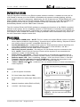
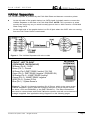
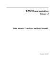
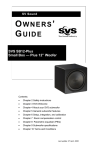
SC-4
4
RS232 SYSTEM CONTROLLER
INSTALLATION
MANUAL
See SC-4 Programming Manual for
Programming Instructions
P/N 40615-143-24 (B)
ELAN
HOME
TABLE
OF
SYSTEMS
SC-4
4
RS232 SYSTEM CONTROLLER
REFERENCE MANUAL
CONTENTS
INTRODUCTION..........................................................................3
FEATURES ..................................................................................3
SYSTEM INTEGRATION ............................................................4
Z!Series, HD Series, and Stand-Alone ............................4
CONNECTIONS ..........................................................................4
System Wire Run Specifications/VIA!Net Overview ......5
VIA!Net Repeaters..............................................................7
USING PVIA WALL PLATES ......................................................8
SYSTEM CONNECTIONS ..........................................................9
PVIA-1 with an ELAN Z!System ......................................9
PVIA-1 with an ELAN HD Series System ......................10
PVIA-1 in a Stand-Alone System (In-Wall and Valet) ....11
PVIA-4 to a PZ6 or PHD12 ..............................................13
PVIA-4 with an ELAN Z!System ....................................14
PVIA-4 with an ELAN HD Series System ......................15
PVIA-10 to a PZ6 or PHD12 ............................................16
PVIA-10 with an ELAN Z!System ..................................19
PVIA-10 with an ELAN HD Series System ....................21
ELAN RS232 OUTPUT CONFIGURATIONS ............................22
SC-4 to HDC2040 Automation Card ..............................22
SC-4 to SR-1 sense/Relay Module..................................23
SC-4 to Z880 Video Controller ........................................23
SC-4 to SR-1 , Z880, and HDC2040 ................................24
SC-4 RS232 TECHNICAL SPECIFICATIONS ..........................24
Page 2
© ELAN Home Systems 2001 • All rights reserved.
ELAN
HOME
SYSTEMS
SC-4
4
RS232 SYSTEM CONTROLLER
REFERENCE MANUAL
INTRODUCTION
The SC-4 System Controller is an RS232 system network interface. It enables as many as 30
VIA! Panels to access up to four RS232 controllable sub-systems including lighting, security,
climate control, and A/V components. Additionally, the SC-4 features one “ELAN RS232 Out” port
which enables serial control of ELAN products without sacrificing one of the DB-9 COMM ports.
ELAN products which may be serially controlled include the HD Series MCU, the SR-1
Sense/Relay Module, and the Z880 Video Controller.
The SC-4 utilizes ELAN VIA!TOOLS software to program the functions of the RS232 controlled
devices in the system. SC-4 compatible versions of VIA!TOOLS (2.0 and later) are available for
download from the ELAN website. VIA!TOOLS v2.0 and later feature ‘point and click’ RS232 protocol libraries which enable the installer to assign prewritten serial commands to any button on
the VIA! Panel with a simple mouse click.
FEATURES
!
!
!
!
!
!
!
Four RS232 COMM ports - NOTE: The SC-4 does not support RS232 control of systems
which require hardware “hand-shaking”. Systems which operate utilizing “Request to Send”
and “Clear to Send” are NOT compatible with the SC-4.
One ELAN RS232 port - enables serial control of ELAN products without sacrificing one
of the DB-9 COMM ports and facilitates RS232 control of the HD MCU, the SR-1
Sense/Relay Module, and the Z880 Video Controller.
VIA! Panel network interface - As many as 30 VIA! Panels may be connected to the
SC-4. NOTE: Three PVIA-10 Precision Panels will be required to accommodate the
maximum number of VIA! Panels (30).
Flash memory upgradable - The SC-4’s firmware is automatically upgraded when a
program is created with a more recent firmware version, and downloaded into the SC-4.
Network Status LED - Red = Initializing, Orange = VIA!’s not found, Green = VIAs OK.
Transmit / Receive indicators for each COMM port - Indicate the transmission and
reception of RS232 data. Green = Transmit, Red = Receive (data in).
“Token” RS232 commands - enable the SC-4 to initiate functions of other manufacturer’s
control systems.
Includes:
!
(1) SC-4 System Controller
!
PC Host Cable (6pin DIN-to-DB9)
!
ELAN RS232 Out cable (6pin DIN-to-6Pin
DIN)
!
Network Interface cable (RJ45-to-RJ45)
!
+16VDC 1.3A Power Supply
Figure 1 - SC-4’s front and rear panel
connections
© ELAN Home Systems 2001 • All rights reserved.
Page 3
ELAN
HOME
SYSTEMS
SC-4
4
RS232 SYSTEM CONTROLLER
REFERENCE MANUAL
SYSTEM INTEGRATION
Z!Series
In an ELAN Z-Series system, the SC-4 may be used:
!
As an interface between the VIA! Panels and enables system information to be fed back
from the Z System using a PZ6 Precision Panel.
!
To enable the VIA! Panels in your Z System to issue serial commands to RS232 controlled
sub-systems.
!
To provide quicker and more reliable control of ELAN’s RS232 controlled components,
including the Z880 Video Controller and the SR-1 Sense/Relay Module.
HD Series
In an ELAN HD Series system, the SC-4 may be used:
!
As an interface between VIA! Panels in the system and and enables system information to
be fed back from the HD Series MCU using the PHD12 Precision Panel.
!
To enable the VIA! Panels in your HD System to issue serial commands to RS232
controlled sub-systems.
!
To provide quicker and more reliable control of ELAN’s RS232 controlled components,
including the HD MCU, the Z880 Video Controller and the SR-1 Sense/Relay Module.
!
To enable control of each zone in the HD system from any VIA! Panel location.
Stand-Alone Systems and TOKEN commands
The ELAN SC-4 may also be used to control RS232-based control systems using VIA! Panels
and PVIA Wall Plates. The SC-4 supports one thousand token commands which enable your
ELAN system to interface with other RS232-based systems. NOTE: The SC-4 does not support
RS232 “hand-shaking”. Systems which operate utilizing 5-wires (Transmit, Receive, Request to
Send, Clear to Send, and Ground) are NOT compatible with the SC-4. See page 26 for more
info.
CONNECTIONS
NOTE: IF YOU ARE UTILIZING AN PVIA-1, PVIA-4, OR PVIA-10 WALL PLATE, IT IS NOT
NECESSARY TO USE THE SC-4’S OWN POWER SUPPLY. THE PVIA WALL PLATES WILL
SUPPLY ADEQUATE POWER TO THE SC-4. ADDITIONALLY, BE SURE TO CONNECT THE
SC-4 TO THE PVIA WALL PLATE ONLY AFTER ALL OTHER CONNECTIONS HAVE BEEN
MADE!
1.
Use the provided DB9-to-six pin DIN cable to connect your computer’s COMM Port to the
‘PC HOST’ terminal on the front of the SC-4. This connection will enable you to download
your completed program and serial data to the SC-4. NOTE: If your PC has a USB port
instead of a serial COMM port, a Belkin USB-to-RS232 converter will be required.
2.
Connect the SC-4’s COMM ports to any RS232 controlled devices in your system (maximum of 4, plus as many as three ELAN RS232 controlled devices, i.e SR-1s, Z880s, or
HD MCU).
3.
Connect your VIA! Panels to the PVIA Wall Plate(s), and make the connection to the
SC-4’s ‘Network Interface’ terminal. NOTE: Be sure to supply power to the VIA! Panels
using the power supply provided with the PVIA Wall Plate(s). See ELAN system-specific
hookup instructions on the following pages.
4.
Use the provided six pin DIN cables to connect the SC-4’s ‘ELAN RS232 OUT’ terminal to
the ELAN SR-1, Z880, or HD Series MCU if applicable. NOTE: If using an SC-4, the SR-1
and Z880 must be serially controlled. IR control of the Z880 is still possible, but AutoBuild
will automatically configure the Z880 for serial control.
5.
If you are not utilizing a PVIA Wall Plate, Connect the supplied 16VDC 1.3A power supply
to the SC-4.
Page 4
© ELAN Home Systems 2001 • All rights reserved.
ELAN
HOME
SYSTEMS
SC-4
4
RS232 SYSTEM CONTROLLER
REFERENCE MANUAL
IMPORTANT! - System Wire Run Specifications and
VIA!Net Overview
The communication link between the SC-4 and all the VIA! Touch Panels in a system is called
the 'VIA!Net'. All VIA!Net wire runs are “home-run” from each VIA! Panel location to a PVIA WallPlate, which serves as the network hub. There are two types of VIA!Nets, a BASIC VIA!Net, and
an EXTENDED VIA!Net.
A BASIC VIA!Net has the following specifications and limitations:
!
Capable of supporting one SC-4 and a maximum of 30 VIA! Touch Panels.
!
The maximum distance between the SC-4 and any one VIA! Touch Panel CANNOT
EXCEED 1000 feet.
!
In a BASIC VIA!Net system, the combined TOTAL LENGTH of the wire runs CANNOT
EXCEED 2000 feet.
An EXTENDED VIA!Net has the following specifications and limitations:
!
Capable of supporting one SC-4 and a maximum of 30 VIA! Touch Panels (same as the
BASIC VIA!Net).
!
The maximum distance between the SC-4 and any one VIA! Touch Panel CANNOT
EXCEED 1000 feet. (Same as the BASIC VIA!Net)
!
In an EXTENDED VIA!Net system, the combined TOTAL LENGTH of the wire runs within
the VIA!Net CAN EXCEED 2000 feet.
!
Even when VIA!Net Repeaters are utilized, the combined TOTAL LENGTH of wire runs
in each “sub-net” still MUST NOT EXCEED 1000 feet.
IMPORTANT! - If the 2000ft total combined wire length (to all the VIA! Panels) is exceeded, an
Extended VIA!Net must be created. This is accomplished by breaking the longest VIA!Net wire
runs into "sub-nets" using VIA!Net Repeaters. NOTE: Using VIA!Net Repeaters does not enable
you to extend the maximum distance to any one VIA! Panel (still 1000ft MAX), but VIA!Net
Repeaters do enable you to increase the number of VIA! Panels on long runs of wire while
ensuring reliable operation of all VIA! Panels in the system.
© ELAN Home Systems 2001 • All rights reserved.
Page 5
ELAN
HOME
SYSTEMS
SC-4
4
RS232 SYSTEM CONTROLLER
REFERENCE MANUAL
#1
#4
#2
PVIA and SC-4
VIA! #1 = 250’
#2 = 500’
#3 = 250’
#4 = 1000’
--------------Total = 2000’
#3
Figure 2 - A BASIC VIA!Net
!
2000ft. MAX combined wire length. Total length of wire run to all VIA!s in the
system DOES NOT exceed 2000ft, therefore VIA!Net Repeaters are not
needed.
!
The length of wire run to any single VIA! Panel MUST NOT exceed 1000ft
#1
#4
#2
PVIA and SC-4
#3
VIA! #1 = 500’
#2 = 800’
#3 = 500’
#4 = 1000’
--------------Total = 2800’
Figure 3 - An EXTENDED VIA!Net
!
The TOTAL combined wire length to all VIA! Panels in the system equals
2800ft. (exceeding the 2000ft. spec.) therefore VIA!Net Repeaters must be
utilized on the longest runs. NOTE: Wire runs WITH VIA!Net Repeaters still
must not exceed 1000ft. in length.
!
As many as 30 wire runs WITH VIA!Net Repeaters may be utilized, as long as
NONE of the individual runs exceed 1000ft in length.
!
The combined length of all wire runs remaining WITHOUT VIA!Net Repeaters
(‘sub-net’) must not exceed 1000ft.
Page 6
© ELAN Home Systems 2001 • All rights reserved.
ELAN
HOME
SYSTEMS
SC-4
4
RS232 SYSTEM CONTROLLER
REFERENCE MANUAL
VIA!Net Repeaters
The VIA!Net Repeater is powered by the PVIA Wall Plate and has two connection points:
!
On the left side of the graphic below is a CAT5 pigtail (included) used to connect the
VIA!Net Repeater to the back of a PVIA Wall Plate. NOTE: This connection is wired
exactly the same way as you would normally punch down a VIA! Panel to a PVIA Wall
Plate using CAT5.
!
On the right side of the graphic below is a RJ-45 jack where the CAT5 wire run coming
from the VIA! Touch Panel is terminated.
Figure 4 - The VIA!Net Repeater with color codes
PINOUT - LEFT TO RIGHT
(FROM REAR, TAB FACING UP)
W/Brown (Pin 8) - 16VDC
Brown (Pin 7) - Ground
W/Green (Pin 6) ZNET RS485 “positive” (16V OK)
Green (Pin 5) - ZNET RS485 “negative“ (GROUND OK)
W/Orange (Pin 4) - VIANET RS485 “positive”
Orange (Pin 3) - VIANET RS485 “negative”
W/BL (Pin 2) - System IR Out
Blue (Pin 1) - System Sense In
87654321
Figure 5 - The SC-4’s Network Interface RJ-45 Pinout, which is the same as the
VIA!Net Repeater’s pinout (with the exception that pins 5 and 6 may be utilized
for either +16V and GROUND, or the ZNET RS485+/-). The ZNet connections
are used to communicate with ELAN Z! Series systems, and will not be harmed if
voltage is applied. See applicable wiring diagrams on the following pages.
© ELAN Home Systems 2001 • All rights reserved.
Page 7
ELAN
HOME
SYSTEMS
SC-4
4
RS232 SYSTEM CONTROLLER
REFERENCE MANUAL
Using PVIA Wall Plates to interface the SC-4
4 with ELAN
Z Series, HD Series, and Stand Alone Systems
The graphics in the following pages illustrate how to connect VIA! Panels to PVIA-1, PVIA-4,
PVIA-10, PZ6, and PHD12 products. Additionally, wiring configurations illustrating how to directly
connect to a Z630 PreAmp Controller or HD Series Dual Zone Card are included.
NOTE: Make these connections to a PZ6 or PHD12 Precision Panel using ELAN C4545 1 and 2
meter cables pre-terminated with RJ45 jacks on both ends. Should you wish to terminate your
own connections, the pinout is provided below. The use of ELAN’s Precision Panels is by far the
easiest and cleanest way to trim out your ELAN Z or HD Series Systems.
PINOUT - LEFT TO RIGHT
(FROM REAR, TAB FACING UP)
W/Brown (Pin 8) - 16VDC
Brown (Pin 7) - Ground
W/Green (Pin 6) ZNET RS485 “positive”
Green (Pin 5) - ZNET RS485 “negative”
W/Orange (Pin 4) - VIANET RS485 “positive”
Orange (Pin 3) - VIANET RS485 “negative”
W/BL (Pin 2) - System IR Out
Blue (Pin 1) - System Sense In
87654321
Figure 6 - The SC-4’s VIA! Network Interface pinouts
NOTE: The Pin 7 and 8 connections (16VDC/GND) may
be used to enable a PVIA Wall Plate’s power supply to
power the SC-4 (recommended). If used in a Stand-Alone
system configuration, the SC-4’s power supply may be used
to provide power to one VIA! Panel only.
Page 8
© ELAN Home Systems 2001 • All rights reserved.
ELAN
HOME
SC-4
4
SYSTEMS
SYSTEM CONNECTIONS
- PVIA-1
1 WITH
AN
RS232 SYSTEM CONTROLLER
REFERENCE MANUAL
ELAN Z !SYSTEM
To SC-4
Figure 7 - An in-wall VIA! Panel powered by a PVIA-1 and connected to a PZ6
Precision Panel to interface with an ELAN Z!Series system (Zone 5 IR
connections shown). Simply connect the SC-4 to the PVIA-1’s “To SC-4” RJ-45
jack.
To SC-4
Min. 18 AWG stranded speaker wire for power
Figure 8 - An in-wall VIA! Panel powered by a PVIA-1 and connected to an ELAN
Z630 WITHOUT a PZ6 Precision Panel.
© ELAN Home Systems 2001 • All rights reserved.
Page 9
ELAN
HOME
SC-4
4
SYSTEMS
SYSTEM CONNECTIONS
(CONT .)- PVIA-1
1
RS232 SYSTEM CONTROLLER
REFERENCE MANUAL
WITH AN
ELAN
HD S ERIES SYSTEM
To SC-4
Figure 9 - An in-wall VIA! Panel powered by a PVIA-1 and connected to a PHD12
Precision Panel to interface with an ELAN HD Series system.
NOTE: the SC-4 is connected to the PVIA-1 In-Wall version’s “To SC-4” output.
Although not shown - The SC-4’s power supply may be used to power both the
SC-4 and a single VIA! Panel.
Min. 18 AWG stranded speaker wire for power
HD Series
Dual Zone
Card
Figure 10 - An in-wall VIA! Panel powered by a PVIA-1 and directly connected to a
HD Dual Zone card (No PHD12).
NOTE: The SC-4 connects to the “To SC-4” connection on the front of the PVIA-1.
Page 10
© ELAN Home Systems 2001 • All rights reserved.
ELAN
HOME
SC-4
4
SYSTEMS
RS232 SYSTEM CONTROLLER
REFERENCE MANUAL
STAND -A
A LONE PVIA-1
1(IN-WALL AND VALET CONFIGURATIONS)
To SC-4
Figure 11 - An in-wall VIA! Panel powered by a PVIA-1 and configured for
operation of a Stand-Alone system. NOTE: the SC-4 is connected to the
PVIA-1 In-Wall version’s “To SC-4” output. Although not shown - the SC-4’s
power supply may be used to power both the SC-4 and a single VIA! Panel.
Connect
power supply
at the Valet or
head-end
location
To SC-4
Figure 12 - A VIA! Valet connected to a PVIA-1 Valet version, then
connected to a PVIA-1 In-Wall version to enable operation of a StandAlone system. NOTE: The SC-4 is connected to the PVIA-1 In-Wall
version’s “To SC-4” output. Although not shown - the SC-4’s power supply
may be used to power both the SC-4 and the VIA! Valet.
© ELAN Home Systems 2001 • All rights reserved.
Page 11
ELAN
HOME
SYSTEMS
SYSTEM CONNECTIONS -
SC-4
4
RS232 SYSTEM CONTROLLER
REFERENCE MANUAL
PVIA-1
1 (V ALET CONTINUED )
Figure 13 - A VIA! Valet powered by a PVIA-1 Valet version and connected to a
PVIA-1 In-Wall version. The PVIA-1 In-Wall is then connected to a PZ6 or PHD12
to be interfaced with an ELAN Z or HD Series system.
NOTE: See FIGURE 7 for the connections between the PVIA-1 and the PZ6, and
FIGURE 9 for the connections between the PVIA-1 and the PHD12 if utilizing an HD
Series system.
ALSO NOTE: For control of RS232 systems, a single RJ45-to-RJ45 cable is used to
connect the SC-4 to the PVIA-1 In-Wall version’s “To SC-4” terminal. Additionally,
although not shown - the SC-4’s power supply may be used to power both the SC-4
and a single VIA! Valet if desired.
Page 12
© ELAN Home Systems 2001 • All rights reserved.
ELAN
HOME
SC-4
4
SYSTEMS
SYSTEM CONNECTIONS -
PVIA-4
4
TO A
RS232 SYSTEM CONTROLLER
REFERENCE MANUAL
PHD12
OR
PZ6
Figure 15- Four VIA! Panels connected to a PVIA-4 for power, then
connected to a PHD12 or PZ6 for interfacing with an ELAN Z or HD
Series system. NOTE: The SC-4 may be powered by the PVIA-4’s
power supply using the RJ45 -to-RJ45 connection between the two
products. ALSO NOTE: Be sure to set the PVIA-4’s Z-BUS jumpers
to the “INT” position.
In-Wall VIA! Panel to PVIA-4 Connections
Figure 16a
VIA! Valet to PVIA-4 Connections
SC-4
Figure 16b
Figure 16a - A VIA! Panel mounted in a wall and connected to the PVIA-4’s “VIA! #1”
Punchdown and Power terminals.
Figure 16b - A VIA! Valet connected to a PVIA-1 Valet version, then connected to a
PVIA-4’s “VIA #1” Punchdown terminals.
NOTE: When using an SC-4, be sure to set the PVIA-4’s Z-BUS jumpers to the “INT”
position.
© ELAN Home Systems 2001 • All rights reserved.
Page 13
ELAN
HOME
PVIA-4
4
SC-4
4
SYSTEMS
WITH AN
RS232 SYSTEM CONTROLLER
REFERENCE MANUAL
ELAN Z !SYSTEM
SC-4
Connecting a PVIA-4 to a Z630 WITHOUT a PZ6 Precision Panel
Figure 17 - The connections between VIA! Panels, a PVIA-4, and an
ELAN Z System with and without a PZ6 Precision Panel. (Use of a PZ6
Precision Panel is suggested).
NOTE: The SC-4 may be powered by the PVIA-4’s power suppy using
the RJ45-to-RJ45 connection between the two products. ALSO NOTE:
In the scenarios described above, be sure to set the PVIA-4’s Z-BUS
jumpers to the “INT” position.
Page 14
© ELAN Home Systems 2001 • All rights reserved.
ELAN
HOME
PVIA-4
4
SC-4
4
SYSTEMS
WITH AN
RS232 SYSTEM CONTROLLER
REFERENCE MANUAL
ELAN HD S YSTEM
Figure 18 - As many as four in-wall VIA! Panels powered by a PVIA4 and
connected to a PHD12 Precision Panel to interface with an ELAN HD Series
system.
NOTE: The SC-4 may be powered by the PVIA-4’s power supply using the
RJ45-to-RJ45 connection between the two products. However, DO NOT
connect the +16V from the PVIA4 to the PHD12 Precision Panel, or to the
HD Dual Zone Card. Doing so may result in damage to the HD Zone Card,
the MCU, or both.
ALSO NOTE: When using an SC-4, be sure to set the PVIA-4’s Z-BUS jumpers to
the “INT” position.
© ELAN Home Systems 2001 • All rights reserved.
Page 15
ELAN
HOME
PVIA-4
4
SC-4
4
SYSTEMS
WITH AN
RS232 SYSTEM CONTROLLER
REFERENCE MANUAL
ELAN HD S YSTEM (CONTINUED )
HD Dual
Zone Card
Figure 19 - Connecting a PVIA-4 to an HD Dual Zone Card WITHOUT using a
PHD12. NOTE: Using a PHD12 Precision Panel for HD Systems is recommended.
See the PHD12 Manual for details. ALSO NOTE: The SC-4 may be powered by
PVIA-4’s power supply using the RJ45 -to-RJ45 connection between the two
products.
PVIA-1
10 C ONNECTIONS
TO A
PHD12
OR
PZ6
COMM Ports x4
and / or
Figure 20 - Connecting as many as ten VIA! Panels to a PVIA-10 for power,
then paralleling data connections to a PHD12 or PZ6 for control of an ELAN Z or
HD Series system.
NOTE: The SC-4 may be powered by the PVIA-10’s power suppy using the
RJ45 -to-RJ45 connection between the two products. ALSO NOTE: Be sure to
set the PVIA-10’s Z-BUS jumpers to the “INT” position.
Page 16
© ELAN Home Systems 2001 • All rights reserved.
ELAN
HOME
SC-4
4
SYSTEMS
RS232 SYSTEM CONTROLLER
REFERENCE MANUAL
PVIA-1
10 ( CONTINUED )
Figure 21 - The connection of remotely located RS232
controllers to the rear of the PVIA-10.
COM 1, 2, 3, or 4
Figure 22 - The PVIA-10’s rear panel punchdown terminals.
These terminals enable remotely located RS232 devices to
be connected to the rear of the PVIA-10 using standard CAT5.
SC-4
#1
#2
#3
Figure 23 - Linking three PVIA-10’s together to enable the maximum of 30
VIA! Panels to be linked to a single SC-4.
NOTE: Any of the 485+/- connections belonging to any VIA! Panel (1-10,
11-20, or 21-30) on each PVIA-10 may be used to link the 485 +/- “busses”
between the PVIA-10 panels.
© ELAN Home Systems 2001 • All rights reserved.
Page 17
ELAN
HOME
SC-4
4
SYSTEMS
RS232 SYSTEM CONTROLLER
REFERENCE MANUAL
PVIA-1
10 ( CONTINUED )
REAR
VIEW!
Figure 24 - As many as 10 VIA! Panels may be connected to a PVIA-10 Precision Panel.
SC-4
Figure 25 - A VIA! Valet powered by a PVIA-1 and connected to a PVIA-10 to
accommodate the necessary data connections.
NOTE: The SC-4 may be powered by the PVIA-10’s power suppy using the
RJ45-to-RJ45 connection between the two products.
ALSO NOTE: When using an SC-4, be sure to set the PVIA-10’s Z-BUS jumpers
to the “INT” position.
Page 18
© ELAN Home Systems 2001 • All rights reserved.
ELAN
HOME
SC-4
4
SYSTEMS
PVIA-1
10
WITH AN
RS232 SYSTEM CONTROLLER
REFERENCE MANUAL
ELAN Z !SYSTEM
SC-4
Figure 26 - As many as 10 VIA! Panels connected to a PVIA-10 for power,
with data connections paralleled between the PVIA-10 and the PZ6 for
connection to an ELAN Z Series system. NOTE: The SC-4 may be powered
by the PVIA-10’s power suppy using the RJ45-to-RJ45 connection between
the two products.
NOT USED
Figure 27 - Connecting a PVIA-10 to a PZ6 to enable the connection of IR, Z485
data and Ground connections from multiple VIA! Panels to an ELAN Z Series system.
NOTE: Use of a PZ6 Precision Panel is suggested.
ALSO NOTE: When using an SC-4, be sure to set the PVIA-10’s Z-BUS jumpers to
the “INT” position.
© ELAN Home Systems 2001 • All rights reserved.
Page 19
ELAN
HOME
SYSTEMS
PVIA-1
10
WITH AN
SC-4
4
RS232 SYSTEM CONTROLLER
REFERENCE MANUAL
ELAN Z !SYSTEM (CONTINUED )
SC-4
Figure 28 - Connection of as many as 10 VIA! Panels to a PVIA-10 (for power). The
PVIA-10 is then connected directly to a Z630 WITHOUT a PZ6 Precision Panel.
NOTE: The SC-4 may be powered by the PVIA-10’s power suppy using the RJ45 -toRJ45 connection between the two products. Use of a PZ6 precision Panel is
recommended. ALSO NOTE: When using an SC-4, be sure to set the PVIA-10’s
Z-BUS jumpers to the “INT” position.
Page 20
© ELAN Home Systems 2001 • All rights reserved.
ELAN
HOME
SC-4
4
SYSTEMS
PVIA-1
10
WITH AN
RS232 SYSTEM CONTROLLER
REFERENCE MANUAL
ELAN HD S YSTEM
SC-4
Figure 28 - As many as 10 VIA! Panels connected to a PVIA-10 for power.
Data connections are then paralleled between the PVIA-10 and the PHD12 for
connection to an ELAN HD Series system. NOTE: The SC-4 may be powered
by the PVIA-10’s power suppy using the RJ45 -to-RJ45 connection between
the two products.
Figure 29 - Connecting a PVIA-10 to a PHD12 to enable the connection of IR,
Status and Ground connections from multiple VIA! Panels to an HD Series system.
NOTE: When using an SC-4, be sure to set the PVIA-10’s Z-BUS jumpers to the
“INT” position.
© ELAN Home Systems 2001 • All rights reserved.
Page 21
ELAN
HOME
SYSTEMS
PVIA-1
10
WITH AN
SC-4
4
RS232 SYSTEM CONTROLLER
REFERENCE MANUAL
ELAN HD S YSTEM (CONTINUED )
SC-4
Figure 30 - Connecting a PVIA-10 to an HD Dual Zone Card WITHOUT using a PHD12.
NOTE: The SC-4 may be powered by the PVIA-10’s power suppy using the RJ45 -toRJ45 connection between the two products. Use of a PHD12 is recommended.
ALSO NOTE: When using an SC-4, be sure to set the PVIA-10’s Z-BUS jumpers to the
“INT” position.
ELAN RS232 O UTPUT CONFIGURATIONS
The rear panel of the SC-4 features an ELAN RS232 OUT port. This port facilitates serial control
of ELAN products without having to sacrifice one of the four DB9 COMM ports.
The diagrams below illustrate how to connect the SC-4 to the various ELAN products capable of
being controlled with RS232.
Figure 31 - The ELAN RS232 OUT terminal used to enable control of an ELAN
HD Series MCU’s HDC2040 Automation Control Card.
NOTE: One 6pin DIN-to-6pin DIN cable is included with the SC-4.
Page 22
© ELAN Home Systems 2001 • All rights reserved.
ELAN
HOME
SYSTEMS
SC-4
4
RS232 SYSTEM CONTROLLER
REFERENCE MANUAL
ELAN RS232 O UTPUT CONFIGURATIONS (C ONT .)
Figure 32 - The SC-4’s ELAN RS232 OUT terminal used to enable control of an
ELAN SR-1 Sense/Relay Module. A maximum of two SR-1s may be connected
using the SR-1’s RS232 IN/THRU terminals.
NOTE: A single 6pin DIN-to-6pin DIN cable is included with the SC-4 and with
each SR-1 Sense/Relay Module.
Figure 33 - The ELAN RS232 OUT terminal used to enable control of as
many as three ELAN Z880 Video Controllers using their RS232 IN/THRU
terminals.
NOTE: A single 6pin DIN-to-6pin DIN cable is included with the SC-4 and
with each Z880 Video Controller.
© ELAN Home Systems 2001 • All rights reserved.
Page 23
ELAN
HOME
SYSTEMS
SC-4
4
RS232 SYSTEM CONTROLLER
REFERENCE MANUAL
ELAN RS232 O UTPUT CONFIGURATIONS (C ONT .)
Figure 34 - The ELAN RS232 OUT terminal used to enable control of as
many as two ELAN SR-1 Sense/Relay Modules, three ELAN Z880 Video
Controllers, and/or an HD Series MCU’s HDC2040 Automation Card using
their RS232 IN/THRU terminals.
NOTE: A single 6pin DIN-to-6pin DIN cable is included with the SC-4, each
SR-1, as well as each Z880.
SC-4
4 RS232 T ECHNICAL SPECIFICATIONS
!
Baud Rates: Standard Windowstm 110 - 115.2K, Asynchronous data transfer.
!
RS232 System Compatibility: Compatible with 3-wire RS232 systems only (RX, TX,
and GROUND).
Page 24
© ELAN Home Systems 2001 • All rights reserved.