1
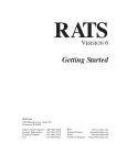
100EM
Tabletop/Under-Cabinet
10" Color Touch Panel
INSTALLATION MANUAL
Important Information
NOTE: This equipment has been tested and found to comply with the limits for a Class
B digital device, pursuant to Part 15 of the FCC Rules. These limits are designed to provide reasonable protection against harmful interference in a residential installation. This
equipment generates, uses and can radiate radio frequency energy and, if not installed
and used in accordance with the instructions, may cause harmful interference to radio
communications. However, there is no guarantee that interference will not occur in a
particular installation.
If this equipment does cause harmful interference to radio or television reception, which
can be determined by turning the equipment off and on, the user is encouraged to try to
correct the interference by one or more of the following measures:
• Reorient or relocate the receiving antenna.
• Increase the separation between the equipment and receiver.
• Connect the equipment into an outlet on a circuit different from that
to which the receiver is connected.
• Consult the dealer or an experienced radio/TV technician for help.
Caution: Changes or modifications not expressly approved by ELAN could void the
user’s authority to operate this equipment.
VIA!VALET100EM
ELAN HOME SYST E M S
Table of Contents
Introduction
...............................................3
Touch Screen Technology
Features
.................................3
..................................................3
Movable Swivel Display . . . . . . . . . . . . . . . . . . . . . . . . . . . . . . . . . . . . . . 4
System Design & Applications
Planning
.........................5
..................................................5
Applications
..............................................7
Stand-Alone/Home Theater . . . . . . . . . . . . . . . . . . . . . . . . . . . . . . . . . . . . 7
Stand-Alone/Home Theater-Expanded . . . . . . . . . . . . . . . . . . . . . . . . . . . . 8
ELAN System12 . . . . . . . . . . . . . . . . . . . . . . . . . . . . . . . . . . . . . . . . . . . . 9
ELAN System8 . . . . . . . . . . . . . . . . . . . . . . . . . . . . . . . . . . . . . . . . . . . . 10
ELAN System6 . . . . . . . . . . . . . . . . . . . . . . . . . . . . . . . . . . . . . . . . . . . . 11
RS-232 Controlled Devices (Regardless of System Type) . . . . . . . . . . . . . . 12
Installation
Pre-Wire
. . . . . . . . . . . . . . . . . . . . . . . . . . . . . . . . . . . . . . . . . . . . . . . 13
. . . . . . . . . . . . . . . . . . . . . . . . . . . . . . . . . . . . . . . . . . . . . . . . . 13
Control, Status, Power . . . . . . . . . . . . . . . . . . . . . . . . . . . . . . . . . . . . . . 13
Video Termination Switch . . . . . . . . . . . . . . . . . . . . . . . . . . . . . . . . . . . . 14
VIA!VALET100EM Touch Panel Connections
Under Cabinet Installation
Connections
. . . . . . . . . . . . . . 15
. . . . . . . . . . . . . . . . . . . . . . . . . . . . . . . 16
. . . . . . . . . . . . . . . . . . . . . . . . . . . . . . . . . . . . . . . . . . . . . 19
Stand-Alone/Home Theater
ELAN System12
. . . . . . . . . . . . . . . . . . . . . . . . . . . . . . 19
. . . . . . . . . . . . . . . . . . . . . . . . . . . . . . . . . . . . . . . . . . 20
ELAN System8
. . . . . . . . . . . . . . . . . . . . . . . . . . . . . . . . . . . . . . . . . . . 21
ELAN System6
. . . . . . . . . . . . . . . . . . . . . . . . . . . . . . . . . . . . . . . . . . . 22
External Power
. . . . . . . . . . . . . . . . . . . . . . . . . . . . . . . . . . . . . . . . . . 23
Local Interface Port
IR Out (LOC)
IR IN
. . . . . . . . . . . . . . . . . . . . . . . . . . . . . . . . . . . . . . 24
. . . . . . . . . . . . . . . . . . . . . . . . . . . . . . . . . . . . . . . . . . . . . 25
. . . . . . . . . . . . . . . . . . . . . . . . . . . . . . . . . . . . . . . . . . . . . . . . . . . . . 26
© ELAN Home Systems 2008 • All rights reserved.
Page 1
VIA!VALET100EM
Sense Port
ELAN HOME SYST E M S
. . . . . . . . . . . . . . . . . . . . . . . . . . . . . . . . . . . . . . . . . . . . . . . 27
Operation . . . . . . . . . . . . . . . . . . . . . . . . . . . . . . . . . . . . . . . . . . . . . . . . . 28
Timeout
. . . . . . . . . . . . . . . . . . . . . . . . . . . . . . . . . . . . . . . . . . . . . . . . . 28
Video Mode
. . . . . . . . . . . . . . . . . . . . . . . . . . . . . . . . . . . . . . . . . . . . . . 28
Video Overlays
Cleaning
. . . . . . . . . . . . . . . . . . . . . . . . . . . . . . . . . . . . . . . . . . . 28
. . . . . . . . . . . . . . . . . . . . . . . . . . . . . . . . . . . . . . . . . . . . . . . . . 28
Cleaning Mode
. . . . . . . . . . . . . . . . . . . . . . . . . . . . . . . . . . . . . . . . . . . 29
Troubleshooting . . . . . . . . . . . . . . . . . . . . . . . . . . . . . . . . . . . . . . . . . . 30
Specifications . . . . . . . . . . . . . . . . . . . . . . . . . . . . . . . . . . . . . . . . . . . . 31
Programming
. . . . . . . . . . . . . . . . . . . . . . . . . . . . . . . . . . . . . . . . . . . . 32
Added Feature
Warranty
Page 2
. . . . . . . . . . . . . . . . . . . . . . . . . . . . . . . . . . . . . . . . . . . 33
. . . . . . . . . . . . . . . . . . . . . . . . . . . . . . . . . . . . . . . . . Back Page
© ELAN Home Systems 2008 • All rights reserved.
ELAN HOME SYST E M S
VIA!VALET100EM
Introduction
The VIA!®Valet100EM Tabletop/Under-Cabinet Color Touch Panel is
an intelligent, affordable solution for controlling audio, video, and
automation equipment in a multi-room environment or as a standalone controller (in a Home Theater, for example). Whether it’s on a
desk in a home office, a nightstand by the bed, in the kitchen on the
counter or mounted under a cabinet, the VIA!Valet100EM is the right
choice. With IR control, RS-232 control, and full-motion video display, it has all of the features that make ELAN’s other award-winning
touch panels the most successful product in their category.
Touch Screen Technology
The VIA!Valet100EM utilizes a polyester plastic film suspended over a
glass panel, which is then adhered to the front of a color LCD (Liquid
Crystal Display) screen. Depressing the polyester film with a finger
allows the film to touch the glass panel underneath, generating a
location signal that is read by the electronics. The 10 inch diagonal
color LCD display is an active matrix TFT Liquid Crystal Display.
Please use fingers only when operating this unit. Do not use pens,
pencils, or styluses as these may damage the polyester film.
Features
• Ideal for Desk or Countertop Use
• Mounts Easily Under Cabinetry
• Folds Down Flat and Out of the Way
• 180° Back/Front 45°- 330°Left/Right Display Swivel
• Full Touch Screen Capabilities
• Full Motion Color Video Capabilities, Widescreen, Landscape Aspect Ratio
• 10 Inch Color Active Matrix TFT Liquid Crystal Display
• IR and RS-232 Control Options
• Easy, Powerful VIA!®Tools Programming
Package Contents
VIA!Valet100EM
PVIA1 Valet Wall Plate
PWR1 16VDC 1 Amp power supply
Cable Assembly
Mounting Template and Hardware
© ELAN Home Systems 2008 • All rights reserved.
Page
Page3 3
VIA!VALET100EM
ELAN HOME SYST E M S
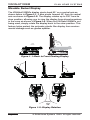
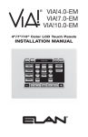
Movable Swivel Display
The VIA!Valet100EM’s display pivots back 90° on a central axis as
shown below in Figure1-1, it also pivots forward 45° from its central
axis as shown in Figure1-2. The display rotates up to 330° from its
stow position, allowing you to view the display from almost anywhere
in the room as shown in Figure1-2. When the VIA!Valet100EM is not
being used, simply rotate the display back to the stow position. This
feature helps protect the polyester plastic film display from environmental damage such as grease splatter.
Display
Face
Stow
Position
Figure 1-1: Back to Front Pivoting Display
45˚
90˚
Display
Face
330˚
Figure 1-2: Display Rotation
Page 4
© ELAN Home Systems 2008 • All rights reserved.
ELAN HOME SYST E M S
VIA!VALET100EM
System Design
Planning
The VIA!Valet100EM can be installed and placed on almost any
flat surface such as a desk, table or countertop, or easily mounted
underneath a cabinet. Because it folds flat, the VIA!Valet100EM can
be tucked neatly out of view when not in use. Before installing the
VIA!Valet100EM it is essential to have a detailed and accurate system design. Talk with the homeowner to make sure all expectations
and design goals are explored. The first step to a good design is to
map the system. It is advisable to mark up a copy of the house floor
plan with speaker, keypad, touch panel, volume control, and equipment locations, etc. Make sure that all locations are decided upon
before pre-wiring commences so that all necessary wiring and installation hardware is in place.
It is essential that ALL system components are accounted for prior
to the pre-wire stage. After establishing design goals with the homeowner, make a detailed list of all components. Include source
equipment, keypads, touch panels, volume controls, amplifiers, communications gear, etc. Gather up any IR remote controls that may be
necessary for final programming, or ensure that the IR codes for all
equipment to be installed are available in the VIA!TOOLS IR Library.
When planning specific under cabinet installation locations for
LCD Touch Panels, please keep the following tips in mind:
• When properly installed, nothing should be applying contact pressure to the touch
panel except for the operator’s finger. If something is touching the touch screen window, a false signal can be generated causing the touch panel to respond incorrectly.
• Avoid installation in direct sunlight or strong ultraviolet light (such as grow lamps
for plants). This can degrade or discolor the polyester film.
• Avoid installation over heat generating devices and/or in moist areas where
condensation can form on the polyester film. Both heat and condensed moisture can
affect touch screen performance.
• Avoid applying any foreign objects, such as adhesive labels, glue, etc. on the touch
screen’s polyester film. This can release chemicals that can discolor the clear film.
© ELAN Home Systems 2008 • All rights reserved.
Page 5
VIA!VALET100EM
ELAN HOME SYST E M S
• The touch panel/LCD assembly should not be mounted near electronics that emit
radio frequencies or electromagnetic interference (such as CRT monitors, light dimmers, and some power supplies).
• Do not mount the VIA!Valet100EM outdoors or in areas exceeding its operating
temperature range of -10°F(-23°C) to +115°F (+46°C). If the LCD display is overheated or its temperature reduced below its recommended minimum, the liquid crystal
polymer can be damaged and the display image may not recover.
Page 6
© ELAN Home Systems 2008 • All rights reserved.
ELAN HOME SYST E M S
VIA!VALET100EM
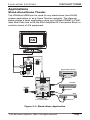
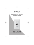
Applications
Stand-Alone/Home Theater
The VIA!Valet100EM can be used for any stand-alone (non-ELAN)
system application or as a Home Theater controller. The diagram
below shows a basic application using one VIA!Valet100EM, a PVIA1
Valet Wall Plate and an ELAN IRD4 Amplified IR Connection Block to
control a stack of A/V equipment.
IR
OUT
PWR1
9VDC PWR9
16VDC PWR1
Digital Music Server
TO VIA VALET
VIDEO
OUT
PVIA1 Valet
IR Emitter
Satellite
PWR2
IR Emitter
DVD
Amplified IR
Connection Block
IR Emitter
Figure 2-1: Stand-Alone Application
© ELAN Home Systems 2008 • All rights reserved.
Page 7
VIA!VALET100EM
ELAN HOME SYST E M S
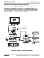
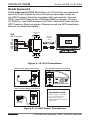
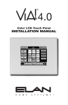
Stand-Alone/Home Theater-Expanded
Stand-alone systems (without an ELAN multi-room controller) can
be as simple as one VIA!Valet100EM controlling one IR source, or
as complex as multiple VIA!70EM's, Ole´Touchpads, and IR sensors all controlling many IR sources. The diagram below shows a
VIA!Valet100EM, A PVIA1 Valet Wall Plate, two VIA!70EMs and a
PVIA4 Wall Plate controlling a stack of A/V gear.
Required only if
connecting more
than 4 VIA!s to the
PVIA4 Wall Plate
PVIA1 Valet
IR
OUT
9VDC PWR9
PWR1
16VDC PWR1
TO VIA VALET
Digital Music Server
VIDEO
OUT
PVIA4
IR Emitter
2
1
1
PVIA-4
3
2
9 VDC
SENSE
INPUTS
+16VDC
POWER
3
IR
OUT
4
Satellite
ALL
SYS
SENSE
4
TO VIA!NET
PWR2
VIDEO
IN
16 VDC/
4A
1
2
3
IR Emitter
4
PWR4
DVD
Amplified IR
Connection Block
IR Emitter
VIA!70EM X2
Figure 2-2: Home Theater Application
Page 8
© ELAN Home Systems 2008 • All rights reserved.
VIA!VALET100EM
ELAN HOME SYST E M S
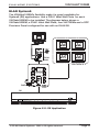
ELAN S12
ELAN’s SPP Precision Panel for the System12 Multi-Room
A/V Controller (S12) makes quick work out of configuring a
VIA!Valet100EM Touch Panel to control S12 zones. Unlike inwall VIA!s, a PVIA1 Valet Wall Plate is necessary when using
a VIA!Valet100EM with an S12. The diagram below shows one
VIA!Valet100EM Touch Panel, one PVIA1 Valet Wall Plate, four
VIA!70EM Touch Panels, and a SPP connected to an ELAN S12.
PVIA1 Valet
IR
OUT
9VDC PWR9
16VDC PWR1
TO VIA VALET
VIDEO
OUT
SPP
VIA!70EM X 4
VIA!NET
EXT IR
TO SENSE INPUTS
1
2
SS/SC4
3
USE STEREO 3.5mm PLUGS ONLY
4
5
6
1
2
3
4
5
6
7
8
ZONE
ZONE
1
5
TRIGGERS
ZONE
2
ZONE
POWER
ZONE
3
ZONE
4
+
6
ZONE
--
16VDC / 10A
7
ZONE
8
PWR10
16VDC
10.0A
16VDC / 4A
16VDC/1.5A
S12
Figure 2-3: S12 Application
NOTE: A PS12 Precision Panel may also be used with a
System12 Multi-Room Controller.
© ELAN Home Systems 2008 • All rights reserved.
Page 9
VIA!VALET100EM
ELAN HOME SYST E M S
ELAN System8
ELAN’s SPP Precision Panel for the System8 Multi-Room A/V
Controller (S8) makes configuring a VIA!Valet100EM Touch Panel to
control S8 zones easy. Unlike in-wall VIA!s, a PVIA1 Valet Wall Plate
is necessary when using a VIA!Valet100EM with an S8. The diagram
below shows one VIA!Valet100EM Touch Panel, one PVIA1 Valet Wall
Plate, four VIA!70EM Touch Panels, and an SPP Precision Panel connected to an ELAN S8.
IR
9VDC PWR9
PWR1
OUT
16VDC PWR1
PVIA1
Valet
TO VIA VALET
VIA!70EM X 4
VIDEO
VIA!NET
EXT IR
OUT
SS/SC4
TO SENSE INPUTS
1
2
3
USE STEREO 3.5mm PLUGS ONLY
4
5
6
2
3
4
ZONE
ZONE
1
5
TRIGGERS
1
ZONE
2
ZONE
5
6
7
POWER
ZONE
3
ZONE
4
+
8
6
ZONE
--
16VDC / 10A
7
ZONE
8
16VDC / 4A
16 VDC/
4A
16VDC/1.5A
PWR4
SPP
S8.6
R
Figure 2-4: S8.6 Application
Page 10
© ELAN Home Systems 2008 • All rights reserved.
VIA!VALET100EM
ELAN HOME SYST E M S
ELAN System6
The VIA!Valet100EM’s flexibility make it a good candidate for
System6 (S6) applications. Use a PVIA1 Valet Wall Plate for each
VIA!Valet100EM to be installed. The diagram below shows a
VIA!Valet100EM, a PVIA1 Valet Wall Plate, four VIA!70EMs and a SPP
Precision Panel configured for use with an ELAN S6.
IR
9VDC PWR9
PWR1
OUT
16VDC PWR1
PVIA1
Valet
TO VIA VALET
VIDEO
OUT
VIA!70EM X 4
VIA!NET
EXT IR
SS/SC4
TO SENSE INPUTS
1
2
3
USE STEREO 3.5mm PLUGS ONLY
4
5
6
1
2
3
4
5
6
7
8
ZONE
ZONE
1
5
TRIGGERS
ZONE
2
ZONE
POWER
ZONE
3
ZONE
4
+
6
ZONE
--
16VDC / 10A
7
ZONE
8
16VDC / 4A
16 VDC/
4A
16VDC/1.5A
PWR4
SPP
S6
R
Figure 2-5: S6 Application
© ELAN Home Systems 2008 • All rights reserved.
Page 11
VIA!VALET100EM
ELAN HOME SYST E M S
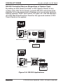
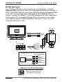
RS-232 Controlled Devices (Regardless of System Type)
By adding an SC4 Serial Controller or SS1 System Station to any
system using VIA! Touch Panels, powerful RS-232 control becomes
possible for a wide assortment of devices such as security systems,
lighting systems, HVAC, spa control, A/V gear, etc. Use the appropriate PVIA Wall Plate/Precision Panel for the type and number of VIA!
Touch Panels in the system.
IR
PWR1
OUT
9VDC PWR9
IR
PVIA10
PVIA4
PVIA1
16VDC PWR1
OUT
2
1
9VDC PWR9
16VDC PWR1
1
VIDEO
OUT
PVIA1
Valet
9 VDC
SENSE
INPUTS
+16VDC
POWER
3
Stand-Alone Systems
4
or
ALL
SYS
SENSE
4
TO VIA!NET
VIDEO
IN
1
VIDEO
3
2
PVIA-4
or
TO VIA!NET
TO VIA VALET
IR
OUT
3
2
4
IN
VIA!SC4
VIA!SS1
or
RS-232
Devices
IR
OUT
PWR1
VIA!SC4
VIA!NET
EXT IR
SS/SC4
TO SENSE INPUTS
1
9VDC PWR9
2
3
16VDC PWR1
USE STEREO 3.5mm PLUGS ONLY
4
5
6
1
2
3
4
5
6
7
8
ZONE
ZONE
1
5
TRIGGERS
ZONE
2
ZONE
POWER
ZONE
3
TO VIA VALET
VIDEO
OUT
ZONE
PVIA1
Valet
4
+
6
ZONE
--
16VDC / 10A
7
ZONE
8
or
VIA!SS1
16VDC / 4A
16VDC/1.5A
SPP
S12, S8, S6 Systems
RS-232
Devices
Figure 2-6: RS 232 Applications
Page 12
© ELAN Home Systems 2008 • All rights reserved.
VIA!VALET100EM
ELAN HOME SYST E M S
Installation
Pre-Wire
The VIA!Valet100EM requires power, control, status and video to
function correctly.
• Control, Status, & Power: Cat-5
• Video: RG-6 or RG-59 Coaxial Cable
Control, Status, Power
Run Cat-5 wire from the main central equipment location to the
location where the touch panel and PVIA1 Valet Wall Plate are to
be installed. The VIA!Valet100EM will be powered locally using the
included PWR1 Power Supply connected directly to the PVIA1 Valet
Wall Plate.
Video
The VIA!Valet100EM has both a Video Input and a Video Loop Output
for Composite Video signals. Run RG-6 or RG-59 coaxial cable from
the head-end location (possibly a video switcher) to the location
where the touch panel and PVIA1 Valet Wall Plate are to be installed.
If desired, the VIDEO Loop output can be routed directly to a
local TV.
VIA!Valet100
PWR1
ELAN S12
Cat-5
TV
RG-59
PVIA1
Valet
Figure 3-1: Overall Wiring Example
© ELAN Home Systems 2008 • All rights reserved.
Page 13
VIA!VALET100EM
ELAN HOME SYST E M S
Be careful not to make sharp bends when installing coax. F-to-RCA
connectors will be necessary to adapt the RCA composite output
of the video source (or switcher) to the F-connector of the coax run.
The VIA!Valet100EM has F-connectors on both the VIDEO IN Input
and VIDEO OUT Output.
Video Termination Switch
When the video signal coming into a VIA! Touch panel is to be
looped back out of the panel to another VIA! or TV, an F connector (VIDEO OUT) is provided. The Video Termination Switch must be
moved from the factory default to the OPEN (HiZ) position.
75 OHM
Termination
Switch
Figure 3-2: Video Termination Switch
Page 14
© ELAN Home Systems 2008 • All rights reserved.
VIA!VALET100EM
ELAN HOME SYST E M S
VIA!Valet100EM Touch Panel Connections
The VIA!Valet100EM Touch Panel comes with a 12’ pre-terminated
bundled cable assembly which includes both Cat-5 and RG-59 coax
cable. To attach the bundled cable between the VIA!Valet100EM
Touch Panel and the PVIA1 Valet Wall Plate:
1. Connect one end of the RG-59 cable to the VIDEO IN port on
the VIA!VALET100EM Touch Panel. Connect the other end to the
VIDEO OUT jack on the PVIA1 Valet Wall Plate.
2. Connect one end of the RJ45 cable labeled “SYS” to the SYS
port on the VIA!Valet100EM. Install cable strain relief clamp.
Connect the other end to the TO VIA VALET jack on the PVIA1
Valet Wall Plate.
3. Optional Local Port Connection: The LOCAL port is not normally
used with the VIA!Valet100EM. If you need to use the LOCAL port,
connect the RJ45 connector labeled “LOCAL” to the LOCAL port
on the VIA!Valet100EM. Connect the other end to other locally
controlled components.
SYS
From VIA!Valet100EM
Touch Panel
IR
9VDC PWR9
OUT
16VDC PWR1
SYS
Cable strain
relief clamp
TO VIA VALET
12’ Pre-terminated
bundled cable
VIDEO
OUT
PVIA1 Valet
To PVIA1 Valet
INSTALLATION TIP:
The LOCAL port is not normally used with the
VIA!Valet100EM. If not using the local connection
ELAN recommends removing the unused
Cat-5 cable by peeling it from the 3-cable
pre-terminated bundle and discarding.
Figure 3-3: PVIA1 Connections
© ELAN Home Systems 2008 • All rights reserved.
Page 15
VIA!VALET100EM
ELAN HOME SYST E M S
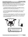
Under Cabinet Installation
The VIA!Valet100EM is ideal for use installed underneath a kitchen or
workshop cabinet. This instruction assumes all pre-wiring has been
previously completed. To install VIA!Valet100EM under a cabinet:
1. Choose an appropriate mounting location underneath the
desired cabinet or shelf.
2. Using the provided VIA!Valet100EM Adhesive Backed
Mounting Template , carefully place the template in position.
Make sure the arrow on the template is pointing toward the
forward edge of the cabinet, as shown below in Figure 3-4 .
3. Using a 3/16” drill bit, create four holes in cabinet from the
center marks made in Step 2.
DO NOT USE FOR VIA!VALET64
CENTERMARK
HOLES FOR MOUNTING
VIA!Valet100EM
Figure 3-4: Template Center Marks
Page 16
© ELAN Home Systems 2008 • All rights reserved.
VIA!VALET100EM
ELAN HOME SYST E M S
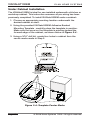
4. Remove the factory installed screw-in feet from the underside
of the VIA!Valet100EM.
Figure 3-5: Remove Feet
5. Measure the thickness of the bottom of the cabinet or shelf.
Select the shortest screw length which will pass completely
through the cup washer and cabinet shelf. Screw length
must protrude from underside of cabinet less than 0.5 inch.
#6-32 SCREW
CUP
WASHER
CABINET SHELF
PROTRUDING SCREW MUST BE LESS THAN
1/2 INCH TO AVOID DAMAGE TO INSIDE
OF THE VIA!VALET100EM.
Figure 3-6: Cabinet Thickness
© ELAN Home Systems 2008 • All rights reserved.
Page 17
VIA!VALET100EM
ELAN HOME SYST E M S
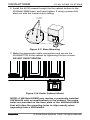
6. Install the #6-32 screws through the the cabinet bottom to the
VIA!Valet100EM base, and hand tighten. If using a power drill,
start out with the lowest clutch setting.
# 6-32 SCREW WITH
CUP WASHER (4)
VIAValet100EM
Bottom
Figure 3-7: Base Mounting
7. Make the appropriate cable connections and secure the
VIA!VALET100 to the cabinet by tightening the four screws.
DO NOT OVER TIGHTEN
Figure 3-8: Under Cabinet Mount
NOTE: A VIA!Valet100EM may replace a previously installed
VIA!Valet64 with no modifications to the cabinet. Two extra
holes are provided on the base plate of the VIA!Valet100EM
that will allow the mounting holes to align exactly when
upgrading from a VIA!Valet64.
Page 18
© ELAN Home Systems 2008 • All rights reserved.
VIA!VALET100EM
ELAN HOME SYST E M S
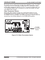
Connections
Stand-Alone/Home Theater
The VIA!Valet100EM is ideal for use as a stand-alone system controller or Home Theater controller. For control of a Home Theater system, the VIA!Valet100EM and PVIA1 Valet Wall Plate are combined
with a method for IR distribution such as ELAN’s IRD4 Amplified
Connection Block. Signals originate at the VIA!Valet100EM, pass
through the PVIA1 Valet Wall Plate, then travel to the connection
block where they are routed to each component.
NOTE: This application does not allow for independent control
of identical sources. An ELAN multi-room preamp,SS1 System
Station or SR-1 System Controller should be used in that scenario.
PVIA1 Valet
Rear
To Front
of PVIA1
Valet
+16V
GND
+16V
GND
V485+
V485-
PWR2
IR
ST/SNS
Z485+
SIR
Z485-
Amplified IR
Connection Block
ELAN
IR Emitters
Sources
Figure 3-9: Stand-Alone Connections
© ELAN Home Systems 2008 • All rights reserved.
Page 19
VIA!VALET100EM
ELAN HOME SYST E M S
ELAN System12
ELAN’s System12 (S12) Multi-Room A/V Controller was designed
with VIA! Touch Panels in mind. Provisions have been made on
the SPP Precision Panel for complete VIA! connectivity. Connect
PVIA1 Valet Wall Plate to the VIA!Valet100EM as shown. Connect
IR, RS485+/- and GND between the PVIA1 Valet Wall Plate and the
SPP Precision Panel as shown. Please consult the SPP Installation
Manual for additional details.
PVIA1 Valet
Rear
SPP
VIA Connector
SN
IR
485485+
GND
+16V
GND
+16V
To Front
of PVIA1
Valet
+16V
GND
+16V
GND
V485+
V485IR
ST/SNS
Z485+
SIR
Z485-
Figure 3-10: S12 Connections
16V/4A Power Supply Connections
16V/10A Power Supply Connections
POWER
POWER
--
+
+
--
16VDC / 10A
16VDC / 10A
16VDC / 4A
16VDC / 4A
16VDC/1.5A
16VDC/1.5A
16VDC
10.0A
16 VDC/
4A
ELAN PWR4
16V/4A
Power Supply
16V/1.5A Power Supply Connections
POWER
+
PWR1
POWER
SUPPLY
--
16VDC / 10A
16VDC / 4A
ELAN PWR1
16V/1.5A
Power Supply
IMPORTANT NOTE
ELAN strongly recommends
the use of a SPP Precision
Panel when installing a
VIA!Valet100EM in a System12
application.
16VDC/1.5A
Figure 3-11: SPP Power Connections
Page 20
© ELAN Home Systems 2008 • All rights reserved.
VIA!VALET100EM
ELAN HOME SYST E M S
ELAN System8
Use a PVIA1 Valet Wall Plate and an SPP Precision Panel when
installing VIA!VALET100 in a System8 (S8). Connect the PVIA1 Valet
Wall Plate to the VIA!Valet100EM as shown. Connect IR, RS485+/-,
and GND between the PVIA1 Valet Wall Plate and the SPP, as shown.
Multiple VIA!s will connect in the same way. Please consult the SPP
Installation Manual for additional details.
R
PVIA1 Valet
Rear
SPP
VIA Connector
+16V
GND
+16V
GND
V485+
V485IR
ST/SNS
Z485+
Z485-
SIR
SN
IR
485485+
GND
+16V
GND
+16V
To Front
of PVIA1
Valet
Figure 3-12: S8 Connections
© ELAN Home Systems 2008 • All rights reserved.
Page 21
VIA!VALET100EM
ELAN HOME SYST E M S
ELAN System6
Use VIA!Valet100EM’s to add functionality and flexibility to ELAN’s
System6 (S6) six-source, six-zone Integrated Multi-Room Controller. A
PVIA1 Valet Wall Plate must be used when interfacing VIA!Valet100EM’s
to an S6. Connect PVIA1 Valet Wall Plate to the VIA!VALET100 as
shown. Connect IR, RS485+/- and GND between the PVIA1 Valet Wall
Plate and the S6, as shown. Multiple VIA!s will connect in the same
way. Please consult the SPP Installation Manual for use of an SPP
Precision Panel with a S6.
PVIA1 Valet
Rear
To Front
of PVIA1
Valet
+16V
GND
+16V
GND
V485+
V485IR
ST/SNS
Z485+
SIR
Z485-
S6
White/Brown
Brown
White/Green
Green
White/Orange
Orange
White/Blue
Blue
ELAN
C45P
Standard ELAN RJ-45 Pin-Out
FRONT
PIN # COLOR CODE
1
2
3
4
5
6
7
8
TAB
BLUE
WHITE/BLUE
ORANGE
WHITE/ORANGE
GREEN
WHITE/GREEN
BROWN
WHITE/BROWN
CABLE
Figure 3-13: S6 Connections
VIA!NET
EXT IR
TO SENSE INPUTS
1
2
SS/SC4
3
USE STEREO 3.5mm PLUGS ONLY
4
5
6
1
2
3
4
5
6
7
8
ZONE
ZONE
1
5
TRIGGERS
ZONE
2
ZONE
3
ZONE
4
ZONE
POWER
+
--
16VDC / 10A
16VDC / 4A
16VDC/1.5A
Page 22
6
ZONE
7
ZONE
8
ELAN Precision Panels save
time and make sense out
of complex wiring jobs!
© ELAN Home Systems 2008 • All rights reserved.
VIA!VALET100EM
ELAN HOME SYST E M S
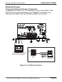
External Power
Using the External Power Connector
In applications where it is not desirable to use a local PVIA1 Valet
Wall Plate is is recommended to use 18AWG 2-conductor wire
between the PWR1 and the VIA!Valet100EM Touch Panel.
G
V+
16 / 18 AWG 2 Conductor
Ext. Power Connector
PWR1
External Power
Connector
Figure 3-14: External Power
© ELAN Home Systems 2008 • All rights reserved.
Page 23
VIA!VALET100EM
ELAN HOME SYST E M S
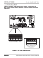
Local Interface Port
Use this connector when utilizing local control features such as
local source control, local IR receivers, or sense-enabled automated
sequences.
Local Interface Port
Local Interface Port
Screw Terminal
Connector
Figure 3-15: Local Interface Port
Page 24
© ELAN Home Systems 2008 • All rights reserved.
VIA!VALET100EM
ELAN HOME SYST E M S
IR OUT (LOC)
The IR OUT (LOC) port is typically used to control a device that is not
part of the main IR system, such as a TV or DVD player located within the same room as the touch panel, or an ELAN Electronic Volume
Control. IR is routed to an emitter or IR distribution block connected
to the IR OUT (LOC) in two ways:
1. Any IR signal that is received from the Local IR Input is sent out
of the Local IR Output RJ-45 Port, the SYS IR Output RJ-45 Port
and the IR OUT (LOC) port from the Interface Port.
IR Emitter
IR OUT (LOC)
IR IN
GROUND
+12 VOLTS OUT
SENSE
2. IR signals may be specified in programming as "Local" and
be routed through the Local IR OUT (LOC) port. See VIA!TOOLS
"Help" file for specific information about IR routing.
IR + = White Stripe
GND = Black
VIA!Valet 100 EM Local
Interface Port
Figure 3-16: IR Out (LOC)
© ELAN Home Systems 2008 • All rights reserved.
Page 25
VIA!VALET100EM
ELAN HOME SYST E M S
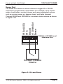
IR IN
The Local IR Input is typically used to connect an external IR receiver to the touch panel. Typical applications include a plasma-friendly
IR receiver (ELAN IRS8EP, for example) placed near a TV, or an auxillary IR receiver placed in an area more convenient than the location
of the touch panel. Any IR signal that is received from the Local
IR Input is sent out the Local IR Output RJ-45 Port, the System IR
Output RJ-45 Port and the IR Out from the Interface Port.
IR OUT (LOC)
IR IN
GROUND
+12 VOLTS OUT
SENSE
Connect IR IN, GROUND, and +12 VOLTS as shown in Figure 3.17.
VIA!Valet 100 EM Local
Interface Port
+12VDC
G
IR
IRS8EP
Extreme Plasma
IR Sensor
Figure 3-17: IR IN
Page 26
© ELAN Home Systems 2008 • All rights reserved.
VIA!VALET100EM
ELAN HOME SYST E M S
Sense Port
The Sense Port allows a contact closure to trigger IR or RS-232
sequences programmed in VIA!TOOLS. For example, use a motion
sensor to activate a contact closure and cause automated actions
such as system power on, drapes closed, and lights dimmed.
IR Out (LOC)
IR In
Ground
+12 Volts Out
Sense
Connect SENSE and GROUND to a contact closure device as shown
in Figure 3.18.
VIA!Valet 100 EM Local
Interface Port
Contact Closure
Device
Figure 3-18: Local Sense
© ELAN Home Systems 2008 • All rights reserved.
Page 27
VIA!VALET100EM
ELAN HOME SYST E M S
Operation
The VIA!Valet100EM is designed to be simple and intuitive to operate. Each source is custom programmed to work just the way the
homeowner desires. This unit is a true touch screen controller; no
hard buttons or stylus required! Use a finger (or fingernail) to lightly
press on the screen each time an action is required.
Timeout
VIA!TOOLS provides separate Timeouts for Source page, Off page,
Lights page, Video, and Cameras. Each of these values should be
set with the homeowner’s lifestyle in mind.
Video Mode/Camera Mode
When in Camera Mode, the VIA!Valet100EM utilizes hidden buttons
on the display that allow for NEXT, PREVIOUS, SCAN ON, SCAN OFF
functionality. A fifth button, EXIT FROM VIDEO MODE, is also present. These buttons are Autobuilt in VIA!TOOLS and will allow the
homeowner to display a specific camera or all cameras, as desired.
See VIA!TOOLS Help file for more specifics.
Video Overlays
Overlays are special pages built in VIA!TOOLS to control video
sources while still viewing the video on the VIA! Each of these overlays is custom built and assigned in programming. See VIA!TOOLS
Help file for more specifics.
Cleaning
To clean the VIA!Valet100EM’s screen, first use a soft dry cloth to
remove contamination. If dirt is still present, use a damp cloth that
has been squeezed of excess water. If dirt is still present, then use a
non-abrasive cleaner or detergent to clean the screen. Use of strong
chemicals and/or some cleaning agents may discolor the polyester
film that makes up the touch screen.
The following products have been tested and approved for cleaning
VIA! Touch Panels:
Windex Glass Cleaner®, Formula 409® Cleaner, and Mr.
Clean®.
Page 28
© ELAN Home Systems 2008 • All rights reserved.
ELAN HOME SYST E M S
VIA!VALET100EM
Cleaning Mode
Cleaning Mode is simply a button created on the VIA!Valet100EM
with a 30 second delay programmed under it. This allows the homeowner to clean the screen without initiating any commands to the
system. The CLEAN button should be placed in a location that the
homeowner or housekeeper can easily remember (see the VIATOOLS
HELP File for more details).
Figure 4-1: Cleaning Mode Programming
© ELAN Home Systems 2008 • All rights reserved.
Page 29
VIA!VALET100EM
ELAN HOME SYST E M S
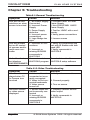
Chapter 5: Troubleshooting
Table5-1:General Troubleshooting
Symptom
Cause
Solution
Unit will not activate/turn-on when
screen is touched
1. No Power Supply
Connected
2. Incorrect Power
Supply
3. Power Supply
defective
4. Incorrect power
connections
5. Logo Badge too
tight
1. Connect PWR1 or PVIA1
Power Supply
2. Use PVIA1/PWR1 16VDC
Power Supply
3. Test for 16VDC with a multimeter
4. Verify power connections
1. Incorrect IR connections
1. Verify IR connections and
test with IR Emitter with talkback LED
2. Verify commands in
VIA!TOOLS
Unit will activate
but no IR control
of sources and/or
multi-room controller
2. Incorrect or
missing IR/RS232
commands in
VIA!TOOLS
5. Loosen screws
Unit will activate,
Does not contain a
Download to unit with
but displays
VIA!TOOLS program VIA!TOOLS setup software
UNPROGRAMMED
Table 5-2: Video Troubleshooting
Symptom
Cause
Solution
No video displayed when TV
or Camera icon
touched
1. Video cable not
connected or incorrectly connected
2. Video In/Out connected backwards
3. Video source
turned off
1. Verify video connections
1. Source video output incorrectly connected
2. Incorrect or
missing IR/RS232
commands in
VIA!TOOLS
1. Properly connect Source
video output
Incorrect camera
or video source
displayed
Page 30
2. Connect properly
3. Turn on source
2. Verify commands in
VIA!TOOLS
© ELAN Home Systems 2008 • All rights reserved.
VIA!VALET100EM
ELAN HOME SYST E M S
Appendix A: Specifications
Table A-1:Specifications
Specifications
Connections
Local Port (RJ-45), System Port (RJ45), Video IN (“F” connector), Video
Loop OUT (“F” connector) Power
Terminal (2 Pin), Local Interface (5
Pin)
Wiring Requirements
Cat-5 (Data), RG-6 or RG-59 coaxial
cable (Composite Video)
Display
High Contrast 10” LCD
Graphics
Resolution
372 pixels (W) 234 lines (H)
Signal
NTSC/PAL (auto-switch) Composite
Video
Viewing Angles
60º Up 40º Down, 45º Left/Right
from Center
Power
16VDC, 1Amp.
Dimensions
11”(W) x 9.8”(H) x 9.2”(folded) (D)
279.4 mm (W) x 248.92 mm (H) x
233.68 mm (folded) (D)
© ELAN Home Systems 2008 • All rights reserved.
Page 31
VIA!VALET100EM
ELAN HOME SYST E M S
Appendix B: Programming
All VIA! Touch Panels must be programmed with ELAN’s
VIA!TOOLS Setup Software using a PC running Windows 98 or
higher. VIA!TOOLS utilizes the VIA!Learner to interface between the
PC and the touch panel to be programmed. It is NOT NECESSARY
to power the VIA!VALET100EM during programming, making it possible to program and download to multiple units prior to installation.
Please see VIA!TOOLS Help file for complete step-by-step information on programming VIA! Touch Panels. Remove black stopper
cap from top of Valet base as shown in Figure B-2 to expose the
Programming Port.
Figure B-1: VIA!TOOLS Programming
Programming Port
Figure B-2: Programming Port
Page 32
© ELAN Home Systems 2008 • All rights reserved.
ELAN HOME SYST E M S
VIA!VALET100EM
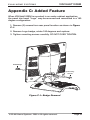
Appendix C: Added Feature
When VIA!Valet100EM is mounted in an under cabinet application,
the panel trim bezel "Logo" may be removed and remounted in a 180
degree configuration:
1. Remove (2) screws from rear panel location as shown in Figure
C-1.
2. Remove Logo badge, rotate 180 degrees and replace.
3. Tighten mounting screws carefully. DO NOT OVER TIGHTEN.
ELAN Badge
(2) Mounting
Screws
Figure C-1: Badge Removal
© ELAN Home Systems 2008 • All rights reserved.
Page 33
VIA!VALET100EM
ELAN HOME SYST E M S
Notes:
Page 34
© ELAN Home Systems 2008 • All rights reserved.
Limited Warranty
ELAN HOME SYSTEMS L.L.C. ("ELAN") warrants the VIA!Valet100EM to be
free from defects in materials and workmanship for the period of two years (2 years)
from date of purchase. If within the applicable warranty period above purchaser
discovers that such item was not as warranted above and promptly notifies ELAN
in writing, ELAN shall repair or replace the item at thecompany's option.
This warranty shall not apply (a) to equipment not manufactured by ELAN,
(b) to equipment which shall have been installed by other than an ELAN
authorized installer, (c) to installed equipment which is not installed to ELAN's
specifications, (d) to equipment which shall have been repaired or altered by others
than ELAN, (e) to equipment which shall have been subjected to negligence, accident,
or damage by circumstances beyond ELAN's control, including, but not limited to,
lightning, flood, electrical surge, tornado, earthquake, or other catastrophic events
beyond ELAN's control, or to improper operation, maintenance or storage, or to other
than normal use of service. With respect to equipment sold by, but not manufactured
by ELAN, the warranty obligations of ELAN shall in all respects conform to the
warranty actually extended to ELAN by its supplier. The foregoing warranties do not
cover reimbursement for labor, transportation, removal, installation or other expenses
which may be incurred in connection with repair or replacement.
Except as may be expressly provided and authorized in writing by ELAN, ELAN shall
not be subject to any other obligations or liabilities whatsoever with respect to
equipment manufactured by ELAN or services rendered by ELAN.
THE FOREGOING WARRANTIES ARE EXCLUSIVE AND IN LIEU OF ALL OTHER
EXPRESSED AND IMPLIED WARRANTIES EXCEPT WARRANTIES OF TITLE, INCLUDING
BUT NOT LIMITED TO IMPLIED WARRANTIES OF MERCHANTABILITY AND FITNESS
FOR A PARTICULAR PURPOSE.
ATTENTION: TO OUR VALUED CONSUMERS
To ensure that consumers obtain quality pre-sale and after-sale support and service,
ELAN Home Systems products are sold exclusively through authorized dealers.
ELAN products are not sold online. The warranties on ELAN products are NOT VALID
if the products have been purchased from an unauthorized dealer or an online E-tailer.
To determine if your ELAN reseller is authorized, please contact ELAN Home Systems
at (859) 269-7760.v
2428 Palumbo Drive Lexington, KY 40509
www.elanhomesystems.com
P/N 9905959 REV: B
MANUAL, VIAVALET100EM
LINEAR P/N 9905959 REV:B (2008)
INK: BLACK
MATERIAL: 60 LB WHITE COATED PAPER
SCALE: 1-1
FLAT SIZE: 11.000X8.500 FLAT, TOL: +/- .40.
FOLD ONCE TO 5.500X8.500
SADDLESTITCH.
ARTWORK CREATED BY ELAN HOME SYSTEMS
NUMBER OF PAGES: 40