1
.
IPMA S.A.
ul. Budowlana 26
20-469 Lublin, Polska
tel. (+48) 81 74 45 071
www.sipma.pl
USER MANUAL
Bale wrapping machine
SIPMA OZ 5000 TEKLA
SIPMA OZ 7500 TEKLA
PKWiU 29.32.33-30.40
ORIGINAL MANUAL
READ THE MANUAL CAREFULLY BEFORE USING THE
MACHINE
13th Edition – 2014
CE Declaration of conformity
SIPMA S.A.
ul. Budowlana 26, 20-469 Lublin, POLSKA
aware of involved liability, hereby declares that the following product:
Bale wrapping machine
Type/model:
SIPMA OZ 5000 TEKLA
SIPMA OZ 7500 TEKLA
SIPMA OS 7510 KLARA
SIPMA OS 7521 MIRA
SIPMA OS 7531 MAJA
SIPMA OR 7532 DIANA
Serial number:
meets the requirements of:
DIRECTIVE 2006/42/EC of the European Parliament and of the Council of 17th May 2006
on machinery, and amending directive 95/16/CE (Official Journal of the European Union L 157 of
9th June 2006, page 24),
and
that it is manufactured within a quality management system compliant with standard ISO 9001,
which is confirmed by the certificate issued by TUV Rheinland Polska Sp. z o.o.:
Person authorized to prepare technical documentation:
R&D Director of the R&D Centre INVENTOR Sp. zoo.- Roman Zarajczyk
R&D Centre INVENTOR Sp. z o.o. ul. Ciepłownicza 4. 20-469 Lublin. POLAND
The following standards were applied in the conformity assessment:
PN-EN ISO 12100:2011
This declaration refers exclusively to the machine in the condition, which the machine was
introduced into the turnover or commissioned, and it does not cover parts added by the final user or
any activities performed by the user later on.
Marketing Director
Lublin, 5th February 2014
Robert Głowacki
NOTE :
The manufacturer delivers the complete machine with a user manual and warranty card. Upon the
receipt of the machine, the buyer should check if all the necessary parts of the machine and
documents were delivered.
This manual includes information concerning usage, lubrication and operation as well as safety
regulations. It describes all available versions and options, including those that are not provided
with the standard version of the machine.
Dear user!
The machine is constantly being developed; therefore SIPMA S.A. reserves the right to implement
any changes or corrections, as appropriate. Under no circumstances may the recipient demand any
modifications to be made to machines that were delivered earlier on the basis of the above.
The efficiency of the machine depends on many factors, connected with the operating conditions.
It is very important to read the manual carefully before operating the machine, and to have it ready
at hand while working. This will enable you to avoid accidents, follow the terms of the warranty
and keep the machine in a good technical condition.
For further information regarding the operation of this and other machines manufactured by the
SIPMA Capital Group and for assistance connected with maintenance service and the spare parts
catalogue, contact our sales representatives.
Supplier:
(the box shall be filled in by the supplier upon selling the baler, and it should include the company's name as well as the
family name, address and telephone number of the contact person and the delivery date)
We are at your disposal – SIPMA S.A. - LUBLIN
Head Office:
Tel.:(48)(081) 744-50-71,
Marketing Department:
Fax: (48)(081) 744-43-56
Tel.:(48)(081) 441-43-09 lub 441-41-14,
Technical Service Department:
744-03-23
Fax: (48)(081) 744-09-64
Tel.:(48)(081) 744-03-23 lub 441-46-18,
Fax:
(48)(081)
Please ensure that after the first operating season the validation form enclosed in this manual
is completed and sent to the manufacturer's address.
For any warranty and service details see the warranty card.
ENJOY THE USE OF OUR PRODUCTS
THE USER MANUAL IS PART OF THE MACHINE EQUIPMENT
KEEP IT FOR FUTURE REFERENCE
3
4
CONTENTS
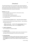
13th Edition – 2014 ....................................................................................................... 3 {INSTRUKCJA ORYGINALNA|ORIGINAL MANUAL} ...................................................................3 {INSTRUKCJA OBSŁUGI|USER MANUAL} ..................................................................................3 1. INTRODUCTION ................................................................................................... 8 2. OPERATION SAFETY AND WARNINGS. ......................................................... 9 2.1. Fire regulations .....................................................................................................................11 3. SAFETY SIGNS.................................................................................................... 12 4. MACHINE IDENTIFICATION............................................................................ 14 5. DESIGNATION OF THE MACHINE AND GENERAL INFORMATION....... 14 6. GENERAL SPECIFICATION AND DESCRIPTION OF THE WRAPPING
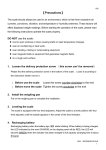
MACHINE .................................................................................................................. 17 7. OPERATION OF THE COUNTER...................................................................... 19 7.1. 7.2. 7.3. 7.4. 7.5. Functions of the counter .......................................................................................................19 Switching on and off.............................................................................................................20 Programming ........................................................................................................................21 Operation ..............................................................................................................................21 Total number of wrappings...................................................................................................22 8. DELIVERY, TRANSPORT, INSTALLATION................................................... 22 8.1. Delivery ................................................................................................................................22 8.2. TRANSPORT .......................................................................................................................24 8.3. INSTALLATION .................................................................................................................24 9. MACHINE USE .................................................................................................... 26 9.1. Starting test ...........................................................................................................................26 9.2. Installing wrapping foil.........................................................................................................27 9.2.1. Bale wrapping machine SIPMA OZ 5000 TEKLA: .......................................................27 9.2.2. Bale wrapping machine SIPMA OZ 7500 TEKLA: .......................................................28 9.3. Loading the bales onto the wrapping machine and wrapping. .............................................29 9.4. Unloading wrapped bales and cutting foil ............................................................................30 9.5. Adjusting the tightening of the drive chain ..........................................................................31 9.6. Reasons of the wrapping machine malfunctions and troubleshooting .................................32 10. EQUIPMENT AND SPARE PARTS ................................................................... 33 11. MAINTENANCE .................................................................................................. 33 12. LUBRICATION INSTRUCTIONS ...................................................................... 34 13. STORAGE ............................................................................................................. 34 14. DISASSEMBLY AND USED PARTS DISPOSAL............................................. 34 15. RESIDUAL RISK DESCRIPTION ...................................................................... 35 15.1. Evaluation the residual risk during operation of the wrapping machine. .............................35 5
16. WARRANTY ........................................................................................................ 35 16.1. Service and post-warranty repairs ........................................................................................35 Product validation........................................................................................................ 36 6
LIST OF FIGURES
Fig. 1 Diagram of foil flow in the feeder ...........................................................................................12 Fig. 2 Assembly method of the wrapping counter. ............................................................................12 Fig. 3 Warning pictogram ..................................................................................................................12 Fig. 4 Information pictogram. ............................................................................................................12 Fig. 5. Read the user manual before beginning to operate the machine ............................................12 Fig. 6 Information pictogram. ............................................................................................................12 Fig. 7. OZ 7500 P Sticker. .................................................................................................................12 Fig.8. OZ 7500 L Sticker. ..................................................................................................................12 Fig.9. OZ 5000 P Sticker. ..................................................................................................................13 Fig.10. OZ 5000 L Sticker. ................................................................................................................13 Fig. 11. Information pictogram. .........................................................................................................13 Fig. 12 Warning! Risk of hand injuries .............................................................................................13 Fig. 13. Direction and number of rotations........................................................................................13 Fig. 14. Direction of rotation. ............................................................................................................13 Fig.15.Arrangement of stickers – view from the left-hand side of the wrapping machine: ..............13 Fig.16.Arrangement of stickers – view from the right-hand side of the wrapping machine: ............13 Fig.17.Arrangement of stickers – view from the front of the wrapping machine: ............................14 Fig.18.Arrangement of stickers – view from the back of the wrapping machine:.............................14 Fig. 19.Diagram of bale wrapping machines SIPMA OZ 5000 TEKLA and SIPMA OZ 7500
TEKLA:.......................................................................................................................................18 Fig. 20 Mounting of the wrapping counter: .......................................................................................23 Fig. 21 Bale wrapping machines SIPMA OZ 5000 TEKLA in the transport position:.....................24 Fig. 22 Hitching of the bale wrapping machine with the tractor: ......................................................25 Fig. 23 Connecting hydraulic hoses to the tractor .............................................................................26 Fig. 24 Bale wrapping machine SIPMA OZ 5000 TEKLA – Installation of a foil roll in the foil
feeder:..........................................................................................................................................27 Fig. 25 Installation of 500mm wide foil in the foil feeder of bale wrapping machine SIPMA OZ
7500 TEKLA:..............................................................................................................................28 Fig. 26. Changing the gear ratio on the rollers...................................................................................29 Fig. 27. Beginning to wrap the bale ...................................................................................................29 Fig. 28. Beginning to unload the wrapped bale .................................................................................30 Fig. 29. Unloaded bale .......................................................................................................................31 Fig. 30. Adjusting the tightening of the drive chain. .........................................................................31 7
1. INTRODUCTION
The user receives this instruction together with the wrapping machine in the sales outlet. The user
should become thoroughly familiar with the contents of the manual.
1) Bale wrapping machine SIPMA OZ 5000 TEKLA/SIPMA OZ 7500 TEKLA can be
operated and used only by individuals who have read the manual carefully, in particular
the section “Operation Safety and Warnings.” The same obligation applies to persons who
undertake to carry out repairs. Non-compliance with the rules of proper use may lead to
an accident or machine failure.
2) The manufacturer delivers the complete machine together with the user manual, a catalogue of
spare parts, the warranty card and the spare parts listed in the chapter “Accessories.” Upon
receipt of the machine, check all the received documents and the conformity of the wrapping
machine number given on the identification plate with the number in the documents.
3) The wrapping machine has no lights. The wrapping machine is equipped with brackets for
installing portable lights and with a bracket on the stand for mounting a warning triangle .
Before driving on any public road, the user is obliged to place a warning triangle and a warning
plate with red light on the brackets of the transport cover. The warning triangle should be
removed when the machine is in use.
4) Hydraulic pipes should be replaced every 5 years after the purchase of the machine. For a
detailed description of the system see the catalogue of spare parts.
5) The manufacturer does not allow for any unauthorised changes in the construction of the
wrapping machine. Any proposals of changes or improvements should be directed and
consulted with the construction department or manufacturer's customer service.
Implementation of any changes without prior agreement exempts the manufacturer from
liability for any consequences of such an implementation and results in termination of the
warranty.
6) Use and operation of the wrapping machine against the user manual exempts the manufacturer
from any liability for incidents resulting from improper use and leads to the termination of the
warranty.
7) In the case of any doubts or questions regarding the information on the wrapping machine use
included in the manual, please contact the supplier or manufacturer's customer service, with the
request for sufficient information.
8
2. OPERATION SAFETY AND WARNINGS.
Please comply with all the general safety regulations concerning the operation of mechanical
equipment when operating or transporting the wrapping machine, and during any service and
maintenance activities.
NOTE:
This warning sign indicates an important piece of information included in this
manual regarding a possible danger. If you see this sign you should be careful,
read the relevant information and inform other operators about it.
NOTE:
This manual is included as a basic accessory of the machine. It should be kept
through the whole period when the machine is used. If the machine is sold or lent
to another user, the manual should be always enclosed. In the case of loss or
destruction of the user manual, please order and purchase a new one from the
vendor.
NOTE:
The manufacturer shall not be responsible for any accidents due to noncompliance with the machine operation safety regulations.
NOTE:
Before any operating, maintenance or adjusting activities, the engine should be
switched off and the ignition key should be removed. The whole unit (the
machine together with the tractor) must be protected against any undesired
movement.
1) The bale wrapping machine can be operated and prepared for operation only by adults who have
a tractor driving licence and who are trained in farming equipment operation safety. The
wrapping machine must not be operated by individuals under the influence of alcohol or any
other intoxicants.
2) Before any operating, maintenance or adjusting activities if the wrapping machine is connected
to the hydraulic system of the tractor, the engine must be switched off and the ignition key must
be removed. The above activities must be performed only when the machine is lowered to the
ground. Walking under the machine lifted on the three point suspension system of the tractor
and leaving the machine in the lifted position are forbidden.
3) It is forbidden for children and underage persons to operate the bale wrapping machine.
4) Protective gloves should be worn during machine operation involving direct contact with the
machine.
5) Before starting the machine and while operating the machine, ensure that there are no people
and in particular no children in the danger zone (near the revolving frame with the wrapping
bale and while unloading the bales from the back of the machine). There should be no other
people and in particular children near the machine when it is being operated or repaired.
6) Be careful while loading and unloading the bales, as they are very heavy.
9
7) Dangerous places have been marked on the machine with yellow safety signs and warning
pictograms. Each sign is described in the chapter “Safety signs”. The user must carefully read
the description of all the signs. While operating the machine, pay particular attention to the
places on the wrapping machine marked with these signs.
8) Before each use, check the technical condition of the machine, in particular focus on the proper
hitching of the wrapping machine to the tractor, the condition of hydraulic system and the
completeness of covers, etc.
9) It is forbidden to operate the machine without covers. The machine must not be operated with
damaged covers.
10) Prior to electric welding, disconnect the alternator and battery cable in the tractor.
11) Do not take any other persons in the tractor. Also there should be no people on the machine
during its operation or transportation.
12) Do not wear any loose clothes that might get caught by the operating elements of the machine.
13) The digital controller and oils supply should be switched off during machine transportation.
14) The wrapping machine must not be transported with a bale inside.
15) Before driving, ensure that the brakes are working properly and check the surroundings of the
machine. Ensure that there are no unauthorised people (children) in blind spots.
16) Never leave the tractor seat while driving.
17) When transporting the wrapping machine on public roads, act with due care and obey the traffic
regulations applicable in the given country. Do not exceed the transport speed limit.
18) The controller (panel) should be operated exclusively, when the operator is seated in the tractor
cab.
19) The set consisting of the tractor and the machine must be obligatorily protected against
accidental operation by third parties, children in particular.
20) Terminals of the hydraulic system pipes should be connected and disconnected from the tractor
only if the pressure in the system is switched off.
21) The pressure in the hydraulic system is very high. When checking for any leakages, use
relevant protective means (e.g. cardboard cover) to avoid any risk of injury. In the case of any
cuts, there is a danger of infection – consult the doctor immediately.
22) All tensile elements (springs) are very dangerous. Particular caution should be exercised in the
zone of their impact. Used parts should be replace exclusively with original manufacturer's
parts.
23) Act with particular caution when hitching the machine to the tractor. When reversing, there
should be no people in the area between the reversing tractor and the wrapping machine.
24) You should not work on the hydraulic system by yourself if you have no practical knowledge
about it or you are not sure of your abilities. Entrust this work to the experts.
10
25) Do not walk between the tractor and the machine until the unit is protected against movement
by putting on the parking brake of the tractor or placing the wedge under the driving wheels.
26) Make sure you know, how to stop the bale wrapping machine and the tractor in case of
emergency.
27) You should be particularly careful when wrapping bales of irregular shape, as while being
wrapped, the bale may fall from the revolving table of the wrapping machine. You should not
wrap the bales with a diameter larger from the one defined in the manual.
NOTE:
The engine of the tractor and the wrapping machine can be started only after
assuring that switching on the drive to the revolving frame does not endanger
anyone. Protect the machine against being accessed by undesirable persons
(children in particular) or animals.
NOTE:
Proper caution should be exercised while close to the bracket, equipped with
sharp knives to cut the foil. Carelessness may result in hands injuries.
2.1. Fire regulations
3. Due to the operating of the wrapping machine with highly flammable materials, you should
strictly comply with the fire regulations and eliminate any risk of fire during operation. Before
use, it is advisable to equip the wrapping machine (tractor) with a working dry powder fire
extinguisher (BCE type).
4. Before starting the work, the wrapping machine should be lubricated according to the
lubrication plan, then start the machine and check that there is no friction between the movable
and the fixed parts of the machine. All the noticed causes of friction of the machine mechanisms
should be removed before the work.
5. No smoking or use of open fire is allowed close to the operating wrapping machines.
6. Before fixing or welding, the machine should be cleaned of any remaining materials that may
cause fire. Before welding, the electric and hydraulic lines, bearings and plastic sleeve housings
should be protected against any damage.
Remember
that the requirements with regard to safety at work as well as road traffic
regulations and fire regulations must be strictly adhered to.
11
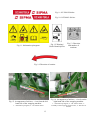
3. SAFETY SIGNS
Particularly dangerous places are marked on the machine with yellow safety signs with warning
pictograms. The user must carefully read the description of the following signs and strictly comply
with the given instructions. When operating the machine, proper care should be taken when near the
marked parts of the machines.
The pictograms placed on the machine are described below:
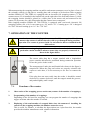
NOTE:
Warning stickers must be always legible. If the stickers are
no longer legible or are damaged, they should be purchased in
the SIPMA SA sales outlets as spare parts and replaced.
Fig. 1 Diagram of foil flow
in the feeder
Fig. 2 Assembly method of the
wrapping counter.
Fig. 4 Information pictogram.
Fig. 3 Warning pictogram
Fig. 5. Read the user
manual before
beginning to operate
the machine
Fig. 6 Information
pictogram.
Fig. 7. OZ 7500 P Sticker.
Fig. 8. OZ 7500 L Sticker.
12
Fig. 9. OZ 5000 P Sticker.
Fig. 10. OZ 5000 L Sticker.
Fig. 12 Warning!
Risk of hand injuries
Fig. 11. Information pictogram.
Fig. 13. Direction
and number of
rotations.
Fig. 14. Direction of rotation.
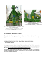
Fig. 15. Arrangement of stickers – view from the lefthand side of the wrapping machine:
1 – information pictogram; 2 – OZ 7500 P sticker.
13
Fig. 16. Arrangement of stickers – view from the
right-hand side of the wrapping machine:
1 – information pictogram; 2 – OZ 7500 L sticker; 3 –
assembly of the wrapping counter sensor; 4 - direction of
rotation.
Fig. 18. Arrangement of stickers – view from the
back of the wrapping machine:
1 - direction and number of rotations; 2 - Warning! Risk of
hand injuries; 3 - warning pictogram.
Fig. 17. Arrangement of stickers – view from the front
of the wrapping machine:
1 – information pictogram; 2 – EU Product sticker; 3- read the
user manual before beginning to operate the machine; 4 –
company plate.
4. MACHINE IDENTIFICATION
The serial number of the wrapping machine can be found on the front beam of the main frame on
the left side of the machine. The identification plate is located next to the serial number (see the Fig.
17-4).
5. DESIGNATION OF THE MACHINE AND GENERAL
INFORMATION
Bale wrapping machines SIPMA OZ 5000 TEKLA and SIPMA OZ 7500 TEKLA are used for
wrapping single bales of semidry hay from grass and leguminous plants of 60% humidity harvested
by the round balers. The bales, after being wrapped with adhesive foil, are ensilaged to produce
hay-silage. The wrapping machine is used for wrapping the bales with foil.
Bale wrapping machines SIPMA OZ 5000 TEKLA and SIPMA OZ 7500 TEKLA are designed for
stationary work on the farm. Moving the balers between the places of work and along roads is also
in accordance with their designation.
14
Any use of the wrapping machine for other purposes will be considered as the use against its
designation. Following and complying with the operating regulations of the wrapping machines as
well as servicing and repairs in accordance with the requirements given in the user manual should
be considered an integral part of the proper use of the machine.
The manufacturer takes no responsibility for any damages or losses that result from the use of
the machine against its designation (as described above). Only the owner and/or the operator
of the machine is responsible for the effects of improper use of the machine
The regulations of accident prevention and all the regulations related to safety at work and
industrial medicine, as well as traffic regulations should always be adhered to.
Bale wrapping machines SIPMA OZ 5000 TEKLA and SIPMA OZ 7500 TEKLA can wrap bales
1.4m long, 1.0 / 1.5 in diameter and 1000 kg in weight. Special foil, which can be purchased from
the suppliers or directly from the manufacturer of the wrapping machines, should be used for
wrapping the bales. The manufacturer is not responsible for any losses incurred due to the use of
improper foil.
The preparation of hay-silage in the form of cylindrical bales wrapped with the foil allows the user
to considerably limit the loss of nutrients when compared with the traditional ways of hay
preparation and with the previous ways of hay-silage preparation in heaps and drive-through silos.
Mowing of grass, mixtures and leguminous plants used for hay-silage (for wrapping) should be
performed when the plants begin to come into ear and when the amount of the nutrients is the
highest (afternoon being the best). The mowed material should be collected with the round balers
after several hours of drying (depending on the weather conditions), i.e. practically on the next day
after the mowing. The bales should be tightly rolled (pressed), so that there is very little air
(oxygen) in the middle of the bale.
After being rolled with the baler, the bales should be wrapped with the wrapping machine as soon
as possible; not later than two hours after being rolled. If you leave the bales unwrapped for a
longer period, the material will become too dry and it will start to rot.
The wrapped bales should be placed within the area of the farm, for the period of a minimum of 6 ÷
8 weeks in a dry place and on a smooth surface. During this period they are under the process of
fermentation. This process should take place in a positive temperature. Check that the foil on the
bales is not damaged. The damaged places should be covered again with the wrapping foil.
The bales can be placed vertically or horizontally, next to each other, in a maximum of two layers.
Two months after being harvested, the hay-silage can be used as fully nutritious fodder.
Currently, the technology of hay-silage production in the form of rolled bales, wrapped with the
foil, is widely used in many countries of the world.
15
TECHNICAL AND OPERATIONAL DATA OF: SIPMA OZ 5000 TEKLA (SIPMA OZ 7500
TEKLA):
Dimensions:
length
working width
transport width
working height
transport height
weight
-
Dimensions of wrapped bales:
diameter
length
Bale weight
Co-operating tractor
-
2.6 m
2.0 m
1.2 m
1.6 m
1.2 m (with disassembled foil feeder)
470 kg (480kg – OZ 7500)
1.2 ÷ 1.5 m
up to 1.3 m
up to 1000 kg
9 kN (0.9T) class
(with power over 30 kW)
Attachment method
of the wrapping machine to the tractor
on a three point system
of the wrapping machine to the tractor
Wrapping machine drive
hydraulic motor SR200
-
Type of oil in hydraulic installation -
Hipol 15 transmission oil
Rotation of the tractor engine
1500 RPM
Rotations of the rollers
2 RPM
Bale loading
available loading devices
with lifting capacity bigger than
the weight of wrapped bales
with the possibility of lifting to 1m
Minimum number of bale wrappings
2x (double with overlaps)
Wrapping counter
electronic with a reed relay sensor and wrapping
number readout in the tractor operator’s cab.
Type of wrapping foil
special polythene foil, 0.025 s 0.03 thick, white,
stretchy, adhesive with a UV ray stabilizer.
Dimensions of a roller with foil wrapped on
foil rolled on a
sleeve with an opening ø 76 mm
Foil width
500 mm (500 and 750mm – OZ 7500)
Maximum diameter of a wrapping
Foil cutting
-
-
260 mm
circular knives on a bracket attached do the revolving frame.
Cutting after loading of the next bale during the first
revolution of the frame. Unloading of wrapped bales by tilting the bottom frame (together with the
revolving frame and bale) after unlocking it (by pulling the cord) and after partial lifting of the
wrapping machine with the three-point system.
Operation of the wrapping machine
one operator (tractor operator)
16
Noise emission level
-
under 70dB
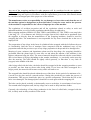
6. GENERAL SPECIFICATION AND DESCRIPTION OF THE
WRAPPING MACHINE
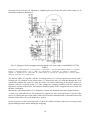
Bale wrapping machines SIPMA OZ 5000 TEKLA and SIPMA OZ 7500 TEKLA (see Fig. 19)
consist of the following units:
– main frame (1),
– bottom frame (2),
– revolving frame (3),
- foil feeder (4),
– hydraulic system (5),
– resistance wheels (6),
– wrapping counter (7).
The main frame (1) of the wrapping machine is attached to the three-point suspension system of the
tractor. The bottom frame (2) is attached do the main frame using two pins (8) secured with spring
cotters.
On the bottom frame there is a revolving frame (3) with rollers (9), on which the bales for wrapping
are loaded. On the vertical bar (11) on the left side of the main frame there is a railing (12) and the
foil feeder (4). Both vertical bars (11) are connected on the top with a connecting channel (13).
The wrapping machine is driven by the tractor hydraulic system with a hydraulic motor (5) through
a special valve (14) ensuring smooth start-up and stopping of the revolving frame with a rolled bale.
The drive from the hydraulic motor is transmitted to the chain wheel of the revolving frame (3) with
a 5/8’’ chain (15). In this way, when the drive is switched on, the revolving frame of the wrapping
machine (together with the bale being wrapped) turns around the vertical axis.
In the revolving frame (3) there is an open conical gear (10) which transmits power, through a shaft
and 5/8’’ chain transmission gears, to the rollers (9).
In this way, during each rotation of the frame (3), the bale loaded on the wrapping machine is also
rotated by the rollers (9) by a small angle around the bale axis.
Wrapping of subsequent foil layers on the bale (bale wrapping) results from the combination of the
abovementioned movements.
The foil feeder (4) in bail wrapping machine SIPMA OZ 5000 TEKLA consists of the frame and a
bracket with rubber rollers (16) coupled through a gear. The foil roller (17) for wrapping is placed
on the feeder frame pin according to the diagram (see Fig. 24). The correctly set ratio between the
rubber rollers and tight adhering of the foil (17) to the rollers (16) ensures foil extension as well as
exact and tight covering of the following layers on the bale. The level of extension of the foil may
be adjusted by tightening the nut of the foil roller clamp (see Fig. 24, item 3). It should amount to
about 60%.
In bail wrapping machine SIPMA OZ 7500 TEKLA, the universal foil feeder (4) for 500 mm and
750 mm foil, consists of the frame and a bracket with aluminium rollers (a) coupled through a gear.
A foil roller (d) for wrapping is placed on the feeder according to the diagram (see Fig. 25). The
correctly set ratio between the aluminium rollers and tight adhering of the foil to the rollers ensures
foil extension as well as exact and tight covering of the following layers on the bale. The level of
17
extension of the foil may be adjusted by tightening the nut of the foil roller brake clamp (i). It
should also amount to about 60%.
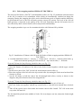
Fig. 19. Diagram of bale wrapping machines SIPMA OZ 5000 TEKLA and SIPMA OZ 7500
TEKLA:
1-main frame, 2 - bottom frame, 3 - revolving frame, 4 - foil feeder, 5 - system with a hydraulic motor.; 6 - resistance
wheels, 7 - wrapping counter, 8 – pin, 9 – rollers, 10 – conical gear,11 - vertical bar, 12 – railing, 13- connecting
channel, 14 – special valve, 15 - main chain, 16 – rubber rollers, 17 - foil roll, 18 – locking pin, 19 – cord, 20 – safety
chain, 21 - foil cutter, 22 – counter sensor
The bottom frame (2) together with the revolving frame (3) is secured against movement with a
locking pin (18) situated on the main frame (1). Moving the pin (18) forward through the lever
system after pulling the cord (19) from the tractor cab causes unlocking of the bottom frame (2)
together with the revolving frame (3). After lifting the wrapping machine with the three-point
suspension system of the tractor, the unlocked frames together with a wrapped bale move back and
the bale is unloaded.
Movement of the bottom frame (2) is limited by a chain (20) attached to the main frame brackets.
A cutter (21) with disk knives for cutting foil is attached to the revolving frame (3) by the roller
drives (9). During the turn of the frame removed foil from the unloaded bale is inserted between the
flat bars of the cutter (21) to the disk knives and cut.
On the cross bars of the revolving frame (3) there are rubber resistance wheels (6) securing a bale
against falling from the rollers during the wrapping.
18
When transporting the wrapping machine on public roads mount a transport cover in place of one of
the resistance wheels (6) and place a warning plate and a triangle on its brackets. Bale wrapping
machine SIPMA OZ 7500 TEKLA is equipped with an electronic foil wrapping counter (7). The
counter sensor (22) is installed in the bracket hole on the right side of the front main frame (1) while
the wrapping counter should be placed in a visible place in the tractor cab and connected to the
sensor (22) by means of a cable. Remember that the counter in not waterproof.
Bale wrapping machine SIPMA OZ 7500 TEKLA is equipped with a universal electronic foil
wrapping counter (x24, x16). It can count up to “24” and to “16”. Counting up to “24” is designed
for “500” foil and counting up to “16” for “750” foil”.
7. OPERATION OF THE COUNTER
An electric conductor leading to the counter should be arranged and fixed in a
manner that ensures it will not interfere with or get damaged during machine
operation. The counter is powered with 2 AAA batteries that are included in the
delivered set.
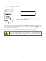
When connecting the plug of the sensor cable to the socket in the counter,
particular caution should be taken to ensure they are properly connected, as
shown in the figure below.
The sensor cable plug has a tongue (marked with a longitudinal
groove outside) that must be positioned during connection operation
to face the groove in the socket.
The arrangement of male pins and female holes shown in the figure is
unequivocal. When the plug and socket are properly oriented with
respect to each other, it is not necessary to use force to connect the
two.
If the plug does not enter easily into the socket, it should be rotated
clockwise or counter clockwise, until the tongues match the grooves,
and pushed lightly, until it snaps.
7.1.
Functions of the counter
1.
Observation of the wrapping process on the run (counter of the number of wrappings).
2.
Programming of the number of wrappings.
Depending on the foil used for wrapping, one can program the number of wrappings that
triggers an alarm when the number is reached.
3.
Displaying of the total number of wrapped bales since the moment of installing the
counter on the wrapping machine (the number cannot be reset).
This is useful, for instance, to calculate the depreciation rate. Apart from this, the number
provides the machine manufacturer with valuable information.
19
7.2.
Switching on and off
In order to switch the device on,
put the sensor cable plug into the
socket on the bottom of the
In order to switch the device on, put the sensor cable plug into the
socket on the bottom of the housing. The liquid crystal display
will get lit, and its status will be 0.
If no impulses are received from the sensor and the button
is not pressed during 2 minutes, the
device switches to the hibernation state. The display is switched off. When the button is pressed,
the device returns to its former state.
To switch the device off, remove the sensor cable plug from the socket in the housing.
If the controller power supply voltage is lower than 2 V, the display will not get
lit up after connecting the power supply. Check the condition of the batteries!
20
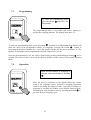
7.3.
Programming
To enter the programming mode,
and hold it for
press the button
10 seconds.
The programming mode is accessible only before starting to
operate the wrapping machine. The display must show "0".
To enter the programming mode, press the button
and hold it for 10 seconds. The display will
show the most recent programmed number of wrappings. Pressing the button
results in
increasing the displayed number by 1. Once the number reaches 48, the device returns to 12. The
number of wrappings can be programmed within the range from 12 to 48.
Once the desired number is set, the value is approved by pressing and holding the button
for 10
seconds. The selected value is stored in the memory and the counter returns to the normal operation
mode.
7.4.
Operation
When the set number of wrappings is
reached, reset the counter by pressing
.
When the device is switched on, the display shows the current
status of the wrapping counter. Successive wrapping operations
result in increasing the displayed value. Once the set number of
wrappings is reached, the number on the display starts to blink.
The displayed value should be reset by pressing the button , to
get on to the next wrapping cycle.
21
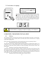
7.5. Total number of wrappings
To read the total number of wrapping
operations, press the button
and hold
it for 10 seconds.
To read the total number of wrapping operations, press the button
and hold it for 10 seconds, when the display shows a value
other than "0". Once this is done, the dispaly will show two
alternate values: one with a dot between digits and one without a
dot. The value with a dot refers to thousands and hundreds, while
the value without a dot refers to tens and unities. For instance:
“1.3"and “51" means: 1351 wrappings.
Only the number of wrappings in completed wrapping cycles is displayed!
8. DELIVERY, TRANSPORT, INSTALLATION
8.1.
Delivery
The wrapping machine can be delivered with some parts disassembled (foil feeder, vertical beams,
connecting channel, railing, resistance wheels, steel back plate, bracket with disk knives, wrapping
counter and coupling parts).
Before starting the wrapping machine, all disassembled parts must be assembled as follows:
a)
Mounting of the main frame to the bottom frame.
The main frame arms of the wrapping machine should be pulled over a bottom frame trapeze so as
to make the axes of ø 36 holes in the frames overlap. Greased pins should be placed in the holes in
the frames on both sides and they should be secured with spring cotters from the inside of the
bottom frame.
b)
Mounting of vertical bars, railings and the foil feeder.
Vertical bars from square pipes should be inserted vertically in the holes in the front part of the
main frame on the right and left sides (by the bottom pins of the three-point suspension system of
the wrapping machine). The railings should be mounted on the left vertical bar and then the foil
feeder. Both vertical bars should be connected with a channel and screwed with M12x70 bolts with
self-locking nuts. All the mounting and locking screws should be tightened.
c)
Mounting of the foil cutter and the rubber resistance wheels.
22
The foil cutter (with disk knives) should be attached to the plate situated on the cross-bar of the
revolving frame from the side of the roller drives. The arms of the cutter should be pointing towards
the outside of the wrapping machine. After tightening, there should be no space between the cutting
disk knives and the bracket of the cutter.
REMEMBER!
Disk knives are very sharp. Particular caution should be exercised when
mounting and operating the wrapping machine due to danger of hand injury.
The rubber wheel brackets should be inserted in the square holes in the cross-bars of the revolving
frame, so that they secure the wrapped bale from sliding from the rollers.
The wrapping machine prepared in this way can be mounted on the three-point suspension system
of the tractor.
Tightening torques of thread joints
Resistance class
Thread size [mm]
M6
M8
M10
M12
M16
M20
M16*1,5
M18*1,5
8.8
10.9
Tightening torque [Nm]
10
15
25
35
50
70
90
120
210
300
410
580
230
320
304
441
d)
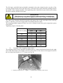
Assembly of the wrapping counter sensor.
The wrapping counter sensor should be installed in the ø 13 hole of the bracket located on the right
side of the main frame so the distance from the front surface of the sensor to the magnet located in
the revolving frame bracket is 15 T 30 mm (see Fig. 20)
Fig. 20. Mounting of the wrapping counter:
1 – wrapping counter sensor; 2 – magnet; 3 – assembly of the wrapping counter sensor;
23
8.2.
TRANSPORT
REMEMBER!
Transporting bales on the wrapping machine on public roads is forbidden. When
transporting an empty wrapping machine on public roads, act with due caution,
observe the traffic regulations applicable in the given country. Do not exceed the
admissible transport speed limit.
Bale wrapping machines SIPMA OZ 5000 TEKLA and SIPMA OZ 7500 TEKLA are attached to a
wooden pallet for transporting.
During loading, unloading and transportation, special precautions should be taken. The pallet with
the wrapping machine should be protected against movement on a platform during transportation.
Bale wrapping machines SIPMA OZ 5000 TEKLA and SIPMA OZ 7500 TEKLA are designed for
stationary work on the farm.
In the case of transporting the wrapping machine on the three-point suspension system of the tractor
on public roads, the wrapping machine hydraulic system must be filled with hydraulic oil and
closed to ensure the blocking of the revolving frame in the lengthwise (transport) position – see Fig.
20. Before setting off do the following:
9 insert the locking pin in the vertical bar of the main frame in order to secure the bottom frame
against moving back,
9 and set the revolving frame in the transport position,
9 mount a transport cover with a warning plate and a triangle on the back of the wrapping
machine frame
9 disconnect the hydraulic pipes of the wrapping machine from the tractor’s hydraulic system.
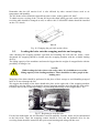
Fig. 21. Bale wrapping machines SIPMA OZ 5000 TEKLA in the transport position:
1 – cover; 2 – foil cutter; 3 – triangular warning plate; 4 – warning plate with red light
8.3.
INSTALLATION
24
NOTE:
Hitch the machine to the tractor with due care.
NOTE:
When in use, the hydraulic system is filled with oil under high pressure which is
very hot (maximum pressure in the system cannot exceed 16 MPa). In the case of
any breakdown or leakage it might be very dangerous.
NOTE:
While changing the quick-attaching coupler, the hose ends and the pipe
connectors should be protected against any contamination, otherwise the tractor
or the hydraulic system of the baler might be damaged.
In order to properly mount the bale wrapping machine on a tractor do the following:
9 dismount the (self-aligning) hook-type coupling from the tractor,
9 set the wrapping machine horizontally on the ground and move the tractor towards it, while
reversing,
9 put both ends of the lower links with the tractor ball-and-socket joints on the two lower bolts of
the wrapping machine and secure them with cotter pins (from the coupling bar pins) (Fig. 22 item 1), adjust the length of the upper tractor connector and connect its end with the coupling
plates on the main frame of the wrapping machine with a shackle bolt and secure with a cotter
pin (Fig. 22 – item 2), the plugs of the hydraulic installation quick attaching couplers should be
placed in the sockets of the tractor’s hydraulic system valves (see Fig. 23)
9 pull the cord of the locking mechanism of the back frame to the tractor cabin and attach its end
in the correct position,
9 place the wrapping counter with a magnetic plate in the tractor cab in a visible place. Connect
the electric wire with a plug to the sensor socket situated on the right side of the main frame of
the wrapping machine. Start the counter with the small lever on the side of its box and reset it by
pressing the button.
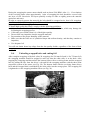
Fig. 22. Hitching of the bale wrapping machine with the tractor:
1 – cotter pin; 2 – shackle bolt; 3 – information pictogram.
25
Fig. 23. Connecting hydraulic hoses to the tractor
The wrapping machine should be levelled before operating
REMEMBER!
All installation work must be done with the engine switched off and the key
removed from the ignition.
NOTE:
For securing pins use only original and working cotter pins. It is forbidden to use
other alternative safety materials such as screws, wires etc.
9. MACHINE USE
9.1.
Starting test
After hitching the wrapping machine to the tractor check the locking mechanism and opening of the
back
frame.
To do this pull the cord in the tractor cab, so the locking pin unlocks the back frame and lift the
wrapping machine on the tractor suspension system. The back and revolving frames should move to
the back. The opening is limited by a chain attached to the main frame brackets.
After lowering the wrapping machine to the horizontal position and releasing the cord, the locking
pin should secure the bottom frame against movement during loading and wrapping of the next
bale.
Then, the hydraulic system of the wrapping machine should be started with due care (after a
warning signal), with the revolving table moving to the left (looking from the top - anticlockwise)
as indicated on the frame. The revolving frame and the shafts should rotate smoothly without
stopping.
At the same time the wrapping counter should be checked. The counter should record each full
rotation of the revolving frame.
26
NOTE:
When starting or operating the wrapping machine (during bale loading,
wrapping and unloading) no people and especially children are allowed near the
working wrapping machine.
NOTE:
Before lifting the wrapping machine by the three-point, the back window of the
tractor cab should be closed.
NOTE:
The motors of the tractor and the wrapping machine hydraulic system can be
started only after assuring that switching on the drive of the revolving frame does
not pose a danger to anyone.
9.2.
9.2.1.
Installing wrapping foil
Bale wrapping machine SIPMA OZ 5000 TEKLA:
NOTE:
When changing the foil roll, switch off the tractor motor and remove the ignition
key.
The roll with special self-adhesive foil for bale wrapping is placed on the foil feeder frame pin, after
moving the bracket with the rubber rollers. The foil roll should be placed, as shown in Fig. 24, and
then it should be secured with a grip from the top and the roll pushed down. The end of the foil
should be pulled through both rollers, exactly as shown on the diagram, and pulled in the direction
of the wrapped bale. Note that after installing the foil, the rubber roller should exactly and evenly
press the foil roll. If an adjustment is necessary, slightly bend the bar on which the foil is placed.
Fig. 24. Bale wrapping machine SIPMA OZ 5000 TEKLA – Installation of a foil roll in the
foil feeder:
1 - foil roll; 2 – rubber rollers; 3 – nut of the foil roll clamp; 4 – pictogram: diagram of foil flow in the feeder.
27
9.2.2. Bale wrapping machine SIPMA OZ 7500 TEKLA:
The universal foil feeder “500/750” with aluminium rollers (see Fig. 25) maintains constant tension
of the foil. It consists of two aluminium rollers which are automatically switched on during the
wrapping. During the wrapping the rollers work with different speeds of rotation and the difference
in speed and the level of the foil roll brake pressure causes foil tension. The level of the foil roll
brake pressure (i) depends on the quality of the foil used. Remember that the foil tension level is
also affected by other external factors such as temperature and humidity.
The wrapping machine is pre-set for wrapping the bales with 500 mm foil by default.
Fig. 25. Installation of 500mm wide foil in the foil feeder of bale wrapping machine SIPMA OZ
7500 TEKLA:
a – knurled aluminium rollers; b – fastener; c – feeder arm; d - foil roll; e – bottom conical roller; g
– feeder arm rotation opening for 500 mm foil; h – top conical roller; i – foil brake.
To install 500 mm foil the following should be done (see Fig. 17):
1. Move the bracket with knurled rollers (a),
2. Open the fastener (b) and move the arm of the feeder forward together with the upper conical
roller (c),
3. Put the lower part of the “500” foil roll (d) in the bottom conical roller (e),
4. Place the top part of the foil roll in the top conical roller (h) turning the feeder arm back until the
fastener is closed.
5. Set the foil brake (i) Pull the end of the foil through both rollers, exactly as shown on the
diagram, and pull in the direction of the wrapped bale.
To install 750 mm foil the following should be done (see Fig. 17):
1. Lengthen the feeder arm by shortening both of its parts in the other pair of holes (f),
2. Move the feeder arm together with the top conical roller (c) into the hole situated above the hole
(g),
3. Take off the special sleeve from under the bottom conical roller. Install “750” foil in the same
way as the 500 mm foil.
The foil should be placed in the middle of a bale. If it is too high or too low, adjust the feeder height
as needed.
28
Remember that the foil tension level is also affected by other external factors such as air
temperature and humidity.
The foil feeder rollers should be cleaned from time to time, as they gather foil “dust”.
To obtain correct covering of the 750 mm foil layers the chain wheel gear ratio on the rollers in the
revolving table should be changed as well; to achieve this 2 10B-69WZ chains should be installed
on the z=21 wheels.
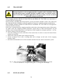
Fig. 26. Changing the gear ratio on the rollers
9.3.
Loading the bales onto the wrapping machine and wrapping.
After checking the wrapping machine operation and installing foil rolls into the feeder, a bale
designated for wrapping should be loaded onto the wrapping machine with the available loading
devices.
The lifting capacity of the machines used must be bigger than the weight of wrapped bales with the
possibility of lifting to 1m.
NOTE:
While loading the bales observe the safety rules. It is forbidden to exceed the
lifting capacity of the loading machines. There should be no other people in the
loading zone.
Wrapping of the bales should be performed in the place of their storage to avoid handling wrapped
bales so as not to damage the foil.
We suggest that loading of the bales should take place on the right side of the wrapping machine
(when the revolving frame is set along the tractor-wrapping machine axis) through the white roller.
It enables the best access during loading, easy unloading and cutting of the wrapped bales’ foil.
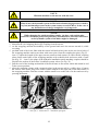
Fig. 27. Beginning to wrap the bale
For the first loaded bale, the foil should be removed manually from the feeder and its end attached
to the bale twine. Then, the wrapping counter should be reset and the hydraulic drive for the
revolving frame should be turned on after prior sound warning and acting with due care.
29
During the wrapping the tractor motor should work at about 1500 RPM. After 11 ÷ 12 revolutions
of the revolving frame (after approximately 1 min. of wrapping) the bale should be covered with
one layer of foil. Successive foil layers partially overlap in order to tightly protect the material
against air and water.
In order to correctly protect the material, the bale should be wrapped twice, that is 24 wrappings
(for 500 mm foil) and 16 wrappings (for 750 mm foil).
Preparing the bales for wrapping:
To obtain high quality hay-silage, comply with the following guidelines:
• Make sure that there are no protruding parts of branches on the bales, which may damage the
foil during the wrapping process
• Collect the green fodder when it is of the highest quality
• Do not allow any impurities into the wrapped materials
• Pay attention to the proper humidity of the material,
• Make sure that the bales are of cylindrical shape and uniform density, and that they contain no
impurities,
• Use adequate foil
You will not obtain better hay-silage from the low quality fodder, regardless of the form of bale
wrapping.
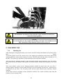
9.4.
Unloading wrapped bales and cutting foil
After complete wrapping of the bale (after 24 wrappings for 500 mm foil and 16 for 750 mm foil)
the wrapping machine should be stopped in such way that the white roller is at the back. After
stopping the wrapping machine unlock the bottom frame with a revolving frame and the wrapped
bale by pulling the line from the driver’s cab and lift the wrapping machine with the three-point
suspension system of the tractor (see Fig. 28). The bottom frame with the revolving frame moves
back and the wrapped bale is unloaded by the white roller into the storage place. The wrapping foil
is tightened over the wrapping machine rollers (see Fig. 29).
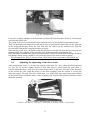
Fig. 28. Beginning to unload the wrapped bale
30
Fig. 29. Unloaded bale
Lower the wrapping machine to the horizontal position and lock the bottom frame by releasing the
cord from the tractor cab.
The spring in the lever system should cause automatic move of the pin locking the bottom frame.
Then, the hydraulic arm should be turned 90o in order to position the white roller on the right side
of the wrapping machine. Place the next bale onto the rollers (on the stretched foil from the
previous bale) and run the wrapping machine as before.
After turning on the drive, the bracket with the disk knives cuts the foil from the previous bale and
simultaneously the wrapping of the next bale starts without manually attaching the foil.
Bales should be unloaded onto prepared smooth and dry surface to avoid the foil damage. Eventual
foil damage during storage should be covered with a proper tape used for bale wrapping.
When changing the foil roll, always switch off the tractor motor and remove the ignition key.
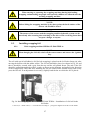
9.5.
Adjusting the tightening of the drive chain
After wrapping the first 10 ÷ 12 bales the tension of the main 5/8’’ drive chain should be adjusted
(see Fig. 30). To do this, slightly unscrew 4 M12 nuts (item 2), which fasten the plate (item 3)
with the hydraulic motor (item 4) to the bottom frame (item 5) and move forward (in the direction
of the tractor) the plate (with the motor) on the bean openings until the tension is correct (the
deflection approx. 20 mm). The drive chain (item 1) is visible after removing trapeze plate behind
on the bottom frame behind the motor. After wrapping each 100 bales the tension of the drive chain
should be checked.
Fig. 30. Adjusting the tightening of the drive chain.
1 – main drive 5/8’’ chain; 2 – M12 nuts; 3 – motor plate; 4 - hydraulic motor; 5 - bottom frame.
31
9.6.
No.
1.
2.
Reasons of the wrapping machine malfunctions and troubleshooting
Description of malfunction
Problems with moving the
locking pin in the main
frame.
The revolving table of the
wrapping machine does not
rotate.
Origin
Solution to the problem
Deformed locking pin or
levers.
Straighten and grease the pin
and levers.
The hydraulic system of the
tractor or the wrapping
machine is out of order.
The main drive chain is
broken.
The chain wheels or the
drive chains are damaged.
3.
The revolving frame shafts
do not rotate.
Check the hydraulic system of
the tractor and the wrapping
machine.
Check the condition of the
chain. Connect the broken
chain links, adjust and
lubricate the chain.
Check the chain wheels and
the roller drive chains.
If the chain wheels are
damaged, change the whole
driving shaft unit welded.
Connect the chain links,
adjust and lubricate the chain.
The bevel gear key in the
Check the bevel gear
intersecting axis gear of the
condition of all the wheels.
revolving frame is
Replace damaged bevel gears.
damaged.
4.
5.
The fed bale wrapping foil
is pulled off (downwards or
upwards).
The wrapping foil is not
tensed properly (during
stops the foil rolls out).
Set the foil feeder exactly at
The foil feeder is mounted
the height of the wrapped bale
too high or too low to the
axis.
wrapped bale axle.
Straighten (bend) the pin on
which the foil roll is mounted
in order to fit the foil roll to
the rubber roll along the
entire length.
The springs tensioning the Check if the arm with rubber
shoulder with rubber rollers rollers is pressed against the
are damaged (or
foil roll.
dismantled).
Replace damaged springs.
The foil roll doesn’t fit
exactly to the rubber roll
along the entire length.
The rubber surface of the
rollers of the foil feeder is
worn-out.
Damaged foil feeder gear.
6.
The wrapping counter does
not count the frame
rotations (number of
Too big space between the
magnet on the revolving
frame and the sensor.
32
Replace foil feeder rubber
rollers.
Check the condition of the
foil feeder gear. Replace
damaged gear wheels.
Adjust the space between the
sensor on the main frame and
the magnet on the revolving
frame to 15 ÷ 30 mm.
wrappings).
Plug-in socket at the sensor
is damaged or soiled.
6F22-9V battery in the
counter is flat.
Clean the plug-in socket and
the plug at the counter and
connect again.
Change the battery for a new
one.
10. EQUIPMENT AND SPARE PARTS
The wrapping machines might be delivered to the sales outlet partly disassembled. The buyer
should receive a complete wrapping machine together with a user manual, a catalogue of spare
parts, a sensor and wrapping counter (additionally in the OZ 7500 wrapping machine together with
2 pieces of 10B-69WZ chains, 1 M12x25-8.8-B-Fe/Zn8 bolt)
The assembly of the separate parts (according to the specifications, as in the parts catalogue) is
described above.
Additional information on the subject of assembly and running the wrapping machine can be found
in our sales outlets. Spare parts and wrapping foil can be bought there as well.
The way of ordering the parts is described at the end of the parts catalogue. Spare parts can be
purchased directly at the manufacturer's or from the machine supplier. Spare parts can be purchased
in the manufacturer's Internet store at the address: http://sklep.sipma.pl
The Spare Parts Catalogue is accessible at the supplier's and it is made available at each request of
an interested party. Whenever spare parts are ordered, the following data should be provided:
a)
machine type, serial number and the year of manufacture (data provided in the
company plate and documentation),
b)
full numbers of figures (standards) and names of parts, including the number of
ordered pieces (from the Parts Catalogue).
c)
precise address of the ordering party.
Information concerning deliveries of spare parts and repairs are provided by the supplier of the
wrapping machine and the servicing department of the manufacturer.
Implementation of original spare parts guarantees high quality of machine operation.
11.
MAINTENANCE
NOTE:
Before any maintenance, the tractor engine must be switched off. The tractor
connected to the machine that is being maintained, should be secured against
possible start-up by any unauthorized persons.
Every day, after work (once the wrapping counter is disconnected), the sensor socket on the
wrapping machine main frame should be covered with foil. In allows you to secure it against
humidity and contamination. After the season or for a longer storage period of the wrapping
machine, the inductive sensor together with the wrapping counter and the whole installation should
be disassembled, dried and stored in a dry place. The wrapping machine should be maintained
periodically, according to the lubrication manual.
33
12.
LUBRICATION INSTRUCTIONS
NOTE:
The lubrication should be performed only after the machine drive and the
tractor engine have been switched off! The tractor connected to the machine that
is being lubricated should be secured against possible start-up by any
unauthorized persons.
Once a year (after the season) servicing of the wrapping machine should be performed, and the
following parts should be lubricated using ŁT-43 lubricant:
• main frame locking pin (1x)
• main frame suspension pins (2x)
• pins connecting the main and bottom frames (2x)
• main drive chain (1x)
• roller drive chains (2x)
• conical wheels of the revolving frame (1x) (visible after unscrewing the frame cover)
• bearing race on the bottom frame (1x)
• disk knives blades (2x).
13.
STORAGE
Before a longer storage period, the wrapping machine should be cleaned and its technical condition
should be checked. Worn-out and broken parts should be verified and the repairs performed.
Eventual corrosion should be removed and the damaged paint renewed. Rubbed surfaces maintain
with grease.
It is recommended to store the wrapping machine in the covered place on the underlay. The foil
feeder (because of rubber rollers) and hydraulic pipes and resistance wheels should be secured
against any exposure to the sunlight.
14.
DISASSEMBLY AND USED PARTS DISPOSAL
When disassembling the machine or its worn-out parts comply with the general safety regulations
applicable when operating the mechanical equipment.
Due to the environment protection requirements, it is advisable to group the disassembled parts
according to the size and material type, release the oil and hand it over to the petrol station. The
machine should be sent to the disposal site, as required by local law regulations.
34
15.
RESIDUAL RISK DESCRIPTION
The highest risk occurs when there are unauthorized persons and in particular children close to the
working wrapping machine. The risk increases if not enough attention is paid to the guidelines in
this manual and the warning stickers, in particular when:
• approaching the machine when it is working
• touching uncovered knife
• operating the wrapping machine on the slopes
• checking the mechanism when the machine is in use.
15.1.
Evaluation the residual risk during operation of the wrapping
machine.
If:
9
9
9
9
9
9
you read carefully the User Manual,
you do not allow any unauthorized persons to approach the working wrapping machine,
you do not allow any children to the working wrapping machine,
you use the wrapping machine in accordance with its designation,
you wear tight clothes (no loose parts),
the wrapping machine is operated by the person who is familiar with the User Manual and
safety regulations,
9 you secure the machine during daily fixing and servicing,
9 the risk for the user will be excluded.
NOTE:
The residual risk will occur when you do not read the described prohibitions and
indications thoroughly enough and do not follow them!
16.
WARRANTY
The wrapping machine has the warranty for the period of 12 months from the date of purchase.
To keep the warranty, the wrapping machine should be used only in accordance with its designation
and maintained according to the chapter “Lubrication manual.”
Use of non-original spare parts may result in the termination of the warranty. For any warranty
details see the warranty card.
16.1.
Service and post-warranty repairs
To keep the warranty, the wrapping machine should be used only in accordance with its designation
and maintained according to the guidelines provided herein. The guarantee becomes null and void if
non-original spare parts (not manufactured by SIPMA S.A.) are used and repairs are performed by
repair establishments that are not authorized by the manufacturer.
NOTE:
Both during the guarantee and post-guarantee period, the manufacturer shall not
be liable for the effects of repairs performed by repair establishments not
authorized by the manufacturer or for the effects of implementing non-original
accessories and parts.
35
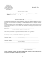
Product validation
Product: Bale wrapping machine
Type: SIPMA OZ………TEKLA
Serial No. ..............
Manufacturer: SIPMA S.A. ul. Budowlana 26 20 - 469 Lublin.
User:
User’s name and address:
..............................................................................................................................................................................
- farm size: up to 100ha,
up to 500ha,
up to 1000ha,
over 1000ha *
- brand, type and power of the tractor used to work with the machine .......................................................................................
- operation life: start date ………………………………, end date …………………………
Requirements of quantity and range of work:
Damages that occurred during work in the operating season
- ..........................................................................., - .........................................................................,
-.............................................................................., - ........................................................................,
- ..........................................................................., - .........................................................................,
- ..........................................................................., - .........................................................................,
Overall machine evaluation:
good
average
bad
− suitability for the assumed designation:
−
failure frequency:
low
medium
high
−
daily operation:
not arduous
too labour-consuming
very arduous
−
hitching to the tractor:
easy
difficult
very difficult
−
design aesthetics:
good
acceptable
bad
−
operation risk:
low
medium
high
−
risk for unauthorized persons and
environment:
low
medium
high
Personal evaluation of the product:
...............................................................................................................................................................
...............................................................................................................................................................
...............................................................................................................................................................
Suggested changes:
...............................................................................................................................................................
...............................................................................................................................................................
...............................................................................................................................................................
* delete irrelevant
I hereby consent for my personal data to be processed for marketing purposes (in compliance with
the act of 29th August 1997, concerning personal data protection, Journal of Laws No. 133, item
883).
..................................................
Stamp and signature of the person filling in the form
* delete irrelevant
36
37
SIPMA S.A.
ul. Budowlana 26
20-469 Lublin, Polska
tel. (+48) 81 74 45 071
www.sipma.pl
Series C, No.
WARRANTY CARD
Name of the machine: Bale wrapping machine
Serial No. .........................
Type: SIPMA OZ………TEKLA
PRODUCTION YEAR ………………………
The manufacturer guarantees the proper operation and quality of the purchased machine and agrees
to bear the costs of its repairs if any damages or manufacturing defects occur during the warranty
period.
The lodged complaint will be acknowledged only if it is ascertained that the machine has been used
properly and in accordance to the user manual. The complaint is valid only upon presentation of the
warranty card.
Date of sale .............................................................................................................
(day, month in words, year – to be filled in by the seller upon selling)
This warranty is valid for the period of 12 months from the date of purchase.
The warranty service, on behalf of the manufacturer is performed by:
Contractor’s name: ....................................................................................................................
(to be filled in by the seller)
Contractor’s address: .....................................................................................................................
(to be filled in by the seller)
......................................................................................................................................................
.....................................................................................................................................................
....................................................................................................
(signature and stamp of the seller)
NOTE FOR THE BUYER: The buyer should read the Warranty Card carefully and not
accept it if it is incomplete or includes any corrections.
38
GENERAL WARRANTY CONDITIONS
1. The warranty applies to the faults and damages which occurred through the fault of the manufacturer,
resulting from material faults, improper working and incorrect assembly.
2. During the warranty period, the manufacturer agrees to repair the claimed equipment free of charge and
cover the costs of spare parts, labour and travelling.
3. The warranty does not cover the parts, which are normally worn out before the expiration of the warranty
period. The list of such parts is included in the user manual.
4. The user complaint is made directly to the seller or to the warranty service performer, defined by the
seller in the warranty card, within the period not longer than 14 days from the failure.
5. The repair, considered as justifiable and resulting from a valid warranty, should be performed forthwith,
but not later than 14 from the moment of notification and physical availability of the machine for repair,
unless the user has given a written consent to extend this period.
6. The person authorized to the warranty service is entitled to exchange the machine for a new one in case
of 4 material failures of the same unit or part.
7. Any damages of the machine occurring during the warranty period through the fault of the user might be
fixed at the user’s cost only by the manufacturer’s representative or persons authorized by the
manufacturer. Only original parts manufactured by the manufacturer of the machine must be used for
repairs.
8. To maintain the machine warranty rights the user (operator) should be trained and have valid certificate
concerning the safe use and operation regulations. The seller’s or manufacturer’s service organizes the
trainings and issues the certificates at the first start-up of the machine or at the sale of the machine. If the
machine is lent to other user, an authorized person is obliged to train this person.
9. The warranty becomes void in the following cases:
•
damage to the machine is caused by accident or collision on the road, regardless of the quality and
technical efficiency of the machine,
•
any structure modifications or changes without written consent of the manufacturer,
•
lack of proper care and operating the machine against its designation as well as continuing the work with
faulty units
•
if the machine damaged has not been checked before any repair
•
a repair is performed by unauthorized servicing entities (of a seller / Trade Partner) and non-original
spare parts (not manufactured by the manufacturer of the machine) are used for repairs,
•
if the user does not allow the repair to be performed or the legitimacy of the complaint to be reviewed.
I have read the warranty conditions
...................................................................................
(Date and signature of the user)
39
WARRANTY REPAIRS RECORD
Repair
start
Date
Repair
end
Date
Complaint
protocol
number
List of
damaged parts
40
Guarantee
extension or
cancellation
Date, signature
Signature and stamp
of the warranty
contractor
41
Stamp of the sales outlet
Series S, No.
COMPLAINT CARD
SIPMA S.A. 20-469 Lublin, ul. Budowlana 26
Name of the machine: Bale wrapping machine
Serial No......................
Type: SIPMA OZ………TEKLA
Date of purchase ........................................................................................................................
(the sales outlet fills in a day, month and year)
Complaint Protocol No. …… ............................................................................................................
Fill in both parts of the card and send to the manufacturer together with the complaint protocol.
Note: Ensure the complaint card is filled in precisely.
Stamp of the sales outlet
Series S, No.
COMPLAINT CARD
SIPMA S.A. 20-469 Lublin, ul. Budowlana 26
Name of the machine: Bale wrapping machine
Serial No......................
Type: SIPMA OZ………TEKLA
Date of purchase .......................................................................................................................
(the sales outlet fills in a day, month and year)
Complaint Protocol No. ...........................................................................................................
Fill in both parts of the card and send to the manufacturer together with the complaint protocol.
Note: Ensure the complaint card is filled in precisely.
42
Additional information for the manufacturer:
.......................................................................................................................................................
................................................................................................................................................................
................................................................................................................................................................
.....................................................................................................................................
................................................................................................................................................................
................................................................................................................................................................
.....................................................................................................................................
.......................................................................................................................................................
.......................................................................................................................................................
After the repair, I accepted the technically efficient equipment on
............................................................
....................................................
User's signature
.........................................
Date, stamp, signature of the warranty service
Additional information for the manufacturer:
.......................................................................................................................................................
................................................................................................................................................................
................................................................................................................................................................
.....................................................................................................................................
................................................................................................................................................................
................................................................................................................................................................
.....................................................................................................................................
.......................................................................................................................................................
.......................................................................................................................................................
After the repair, I accepted the technically efficient equipment on
............................................................
....................................................
User's signature
.........................................
43
Date, stamp, signature of the warranty service
Stamp of the sales outlet
Series S, No.
COMPLAINT CARD
SIPMA S.A. 20-469 Lublin, ul. Budowlana 26
Name of the machine: Bale wrapping machine
Serial No......................
Type: SIPMA OZ………TEKLA
Date of purchase ........................................................................................................................
(the sales outlet fills in a day, month and year)
Complaint Protocol No. ...........................................................................................................
Fill in both parts of the card and send to the manufacturer together with the complaint protocol.
Note: Ensure the complaint card is filled in precisely.
Stamp of the sales outlet
Series S, No.
COMPLAINT CARD
SIPMA S.A. 20-469 Lublin, ul. Budowlana 26
Name of the machine: Bale wrapping machine
Serial No......................
Type: SIPMA OZ………TEKLA
Date of purchase .......................................................................................................................
(the sales outlet fills in a day, month and year)
Complaint Protocol No. ...........................................................................................................
Fill in both parts of the card and send to the manufacturer together with the complaint protocol.
Note: Ensure the complaint card is filled in precisely.
44
Additional information for the manufacturer:
.......................................................................................................................................................
................................................................................................................................................................
................................................................................................................................................................
.....................................................................................................................................
................................................................................................................................................................
................................................................................................................................................................
.....................................................................................................................................
.......................................................................................................................................................
.......................................................................................................................................................
After the repair, I accepted the technically efficient equipment on
............................................................
....................................................
User's signature
.........................................
Date, stamp, signature of the warranty service
45
Place for notes:
………………………………………………………………………………
………………………………………………………………………………
………………………………………………………………………………
………………………………………………………………………………
………………………………………………………………………………
………………………………………………………………………………
………………………………………………………………………………
………………………………………………………………………………
………………………………………………………………………………
………………………………………………………………………………
………………………………………………………………………………
………………………………………………………………………………
………………………………………………………………………………
………………………………………………………………………………
………………………………………………………………………………
………………………………………………………………………………
………………………………………………………………………………
………………………………………………………………………………
………………………………………………………………………………
………………………………………………………………………………
………………………………………………………………………………
………………………………………………………………………………
………………………………………………………………………………
46
………………………………………………………………………………
………………………………………………………………………………
………………………………………………………………………………
………………………………………………………………………………
………………………………………………………………………………
………………………………………………………………………………
………………………………………………………………………………
………………………………………………………………………………
………………………………………………………………………………
………………………………………………………………………………
………………………………………………………………………………
………………………………………………………………………………
………………………………………………………………………………
………………………………………………………………………………
………………………………………………………………………………
………………………………………………………………………………
………………………………………………………………………………
………………………………………………………………………………
………………………………………………………………………………
………………………………………………………………………………
………………………………………………………………………………
………………………………………………………………………………
………………………………………………………………………………
47