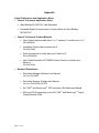
1
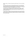
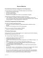
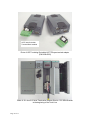
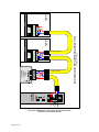
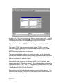
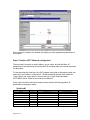
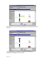
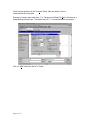
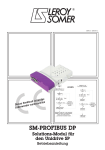
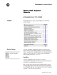
Start Up Guide for UD77 DeviceNet Systems Version 1.00 August 2000 Control Techniques, 2000 P/N UD77-SUG SLC 500 Page 1 of 77 Unidrive UD77 DeviceNet Start-Up Guide Overview This Start-Up Guide is intended to aid installation of one or more Unidrives, each fitted with the UD77 DeviceNet option and an Allen Bradley Modular SLC 500 PLC. This guide presents an example start up of a SLC 5/04 PLC used with a 1747-SDN DeviceNet Scanner and two or more Unidrives, each Unidrive fitted with the UD77 DeviceNet option. However, the same principles should apply when using the SLC 5/02, or SLC 5/03, or SLC 5/05 (other types of SLC) in conjunction with a 1747-SDN DeviceNet Scanner. This guide could also provide some limited guidance for installing the MD25 DeviceNet interface for the Mentor 2 with a SLC 500 PLC. WARNING This guide does not address power wiring and associated safety practices. Start-up of this nature can be hazardous and should only be performed by qualified technicians familiar with motors and drives of this sort. This guide is meant to supplement the Unidrive Installation Manual and the User’s Guide which must be consulted (specifically section 2-1 in the User Guide) prior to this guide being used. Power wiring, keypad operation and related instructions are to be found in these manuals. A experienced start-up engineer will be able to apply previous experience when a line is being commissioned that uses a DeviceNet fieldbus to link the PLC to the Unidrives. Prior to the application of power, the engineer will need to determine if that section of the system is both safe and ready for power to resume. The engineer will also need to check, correct and validate the entire “process pyramid” in manageable pieces and will need to proceed in a thorough and systematic manner until everything is functioning as designed and as required. The experienced startup engineer will learn the techniques used to establish and validate useful communication and control links from the PLC(s) to the Unidrives via DeviceNet. The engineer will also learn how product configuration information from Control Techniques, with softwarebased configuration tools from other vendors, is integrated to establish the required communication and control links on a system that uses a DeviceNet fieldbus. Every complex control scheme can be broken down and evaluated as a series of combinations of a simple control scheme. The simple control scheme presented in this guide consists of a single executive controller and two controlled Motor / Drive / Machine-process Sections, with some form of communication and control link between the controller and the controlled. On a Control Techniques supplied DeviceNet system, the executive controller is usually a separate PLC or Process computer with some form of Human Interface, and the controlled Drive is a Page 2 of 77 Unidrive (or Mentor 2 or Quantum 3) fitted with a DeviceNet Interface. The link is a DeviceNet fieldbus. In the context of modern “smart” and “programmable” Motor Drives, such as the Unidrive, the default configuration provided serves as the standard product design. The use of the default DeviceNet configuration files is illustrated in this guide, as is the configuration and establishment of the default cyclic links between the 1747-SDN Scanner and the Unidrives. DeviceNet Manager (and RSLogix500 as well) is organized around the concept of a “project”. In this sense, a “project” functions as a “container” for the various files and data structures created (or needed) by the program during the specification and configuration of one or more related DeviceNet networks. This start up guide is organized as a series of blocks that take the reader through the required concepts and tasks for installation of the hardware and software and for creation of a DeviceNet project. References to other materials for guidance about tasks not covered here are provided at the end of the document. Page 3 of 77 Table of Contents OVERVIEW................................................................................................................................................................ 2 TABLE OF CONTENTS............................................................................................................................................ 4 REQUIRED MATERIALS ........................................................................................................................................ 5 DEVICENET NETWORK SOFTWARE CONFIGURATION TOOLS REQUIREMENTS ........................................................... 5 SLC 500 PLC PROGRAMMING TOOLS REQUIREMENTS ............................................................................................. 5 PC HARDWARE REQUIREMENTS ................................................................................................................................ 5 FUNCTIONAL DEVICENET NETWORK HARDWARE REQUIREMENTS ........................................................................... 6 HARDWARE INSTALLATION ............................................................................................................................... 9 STEP 1. ASSEMBLE MODULES AND SLC RACK INTO A COMPLETE PLC .................................................................... 9 STEP 2. ASSEMBLE THE DEVICENET NETWORK ...................................................................................................... 10 STEP 3. USING A “EMPTY.RSS” PROJECT .............................................................................................................. 15 DEVICENET MANAGER INSTALLATION ....................................................................................................... 16 STEP 1. DEVICENET MANAGER INSTALLATION TO HARD DRIVE ............................................................................. 16 STEP 2. INSTALLATION OF CONTROL TECHNIQUES “EDS” FILES TO DEVICENET MANAGER .................................. 18 STEP 3. CREATION OF THE “FIRST” DEVICENET PROJECT WITH DEVICENET MANAGER ....................................... 22 STEP 4. CONFIGURING INITIAL “INTERFACE-TO-SCANNER” COMMUNICATION ....................................................... 24 STEP 5. UNIDRIVE UD77 NETWORK CONFIGURATION ............................................................................................. 28 STEP 6. DEFINING AND MAPPING CYCLIC LINKS ..................................................................................................... 30 RSLOGIX500 AND RSLINX LITE USE ............................................................................................................... 50 STEP 1. CONFIGURING INITIAL COMMUNICATION TO THE SLC 500......................................................................... 50 STEP 2. USING AN “EMPTY.RSS” PROJECT TO INITIALIZE A SLC 5/0X PROCESSOR .............................................. 59 STEP 3. USING A “FIRST.RSS” PROJECT TO CONFIRM DEVICENET NETWORK....................................................... 59 STEP 4. SLC FAULT-AT-RUN TROUBLESHOOTING................................................................................................... 69 STEP 5. CLOSING RSLOGIX500 AND RSLINX LITE .................................................................................................. 74 APPENDIX................................................................................................................................................................ 77 USEFUL PUBLICATIONS AND APPLICATION NOTES .................................................................................................. 77 Page 4 of 77 Required Materials DeviceNet Network Software Configuration Tools Requirements DeviceNet Manager for Windows (P/N 1787-MGR available from Allen Bradley) • Version 3.01 is the minimum usable • Ver 3.04 is current product • Ver 3.02 is used in this guide • RSNetWorx for DeviceNet (is also usable, but not described in this guide) Generic Electronic Data Sheets, bitmap and icon files for the Unidrive • *.EDS, *.BMP and *.ICO files for Unidrive and Mentor 2 are available for free from the Control Techniques SSPD support site and any Control Techniques Drive Center. These are usually distributed as a single compressed file, “DEVNET.ZIP”. SLC 500 PLC Programming Tools Requirements SLC 500 PLC Program Development Software • RSLogix500 (P/N 9324-RL0300ENx is English/Standard edition available from Allen Bradley) • Version 3.01.09 is illustrated, Ver 3.0x.0x is current product RSLinx Lite (is included on RSLogix installation CDROM) • Version 2.0.18 minimum for use with DeviceNet PC Hardware Requirements Recommended PC minimums reflect the guide’s use of a single serial port for both configuring the fieldbus and programming the SLC 500. PC - Pentium Class PC @100 MHz or better with: • • • • • • • 32 MB available RAM with Win95 or Win98 for OS 64 MB available RAM with NT4.0 for OS 120 MB Total Hard Disk Space free (20 MB for Applications, and 100 MB for OS swap file use) CDROM quad-speed or better (for loading of RSLogix500 and RSLinx Lite) 3 ½ “ 1.44 MB floppy drive (needed for RSLogix500 and loading DeviceNet Manager) 1 available serial port, 16550 compatible UART Mouse and suitable port (PS-2 style requires PS-2 port, serial mouse requires a second serial port) Note that NT4.0 requires “Local Administrator” or “Power User” privileges to install software on the machine. Use the latest applicable OS Service Release(s) available. Also note that, while this guide has not been tested with Windows 2000, the requirements should be similar to the NT 4.0 requirements, and it is assumed that the tasks described in this guide can also be accomplished under Windows 2000 Professional. Page 5 of 77 Functional DeviceNet Network Hardware Requirements Note: This guide describes a small DeviceNet network, or something larger that has been reduced to two Unidrives and two UD77s. Modular SLC 500 PLC, SLC 5/02 processor or better. • SLC 5/04 is recommended, unless additional Ethernet connectivity required. • SLC 5/05 is recommended if additional Ethernet connectivity is needed. SLC 500 modular chassis Needed to house the power supply, processor, scanner and I/O module(s). A 1746-A4 4slot-rack is described in this guide. SLC 500 power supply A 1746-P1 rated at 2.0A/0.46A (at 5 V/24V) is described in this guide. At least one Discrete Input Module. • A “1746-IO12DC” combination input/output module is recommended for a small DeviceNet network and is described, but not used, in this guide. 1747-SDN DeviceNet scanner module PC-to-DeviceNet interface This is required for configuring the scanner, and useful for commissioning the Unidrives. • • • M/N 1770-KFD RS-232 interface is described in this guide. This interface can take its power directly from the DeviceNet 24.0 VDC supply, so an optional 9.0 VDC supply is not required unless isolating point-to-point taps are used with the interface. Note that the interface cable that comes with this scanner can also be used as a 1747-CP3 cable into channel 0 of the processor to permit communication between the processor and the PC. M/N 1784-PCD PCMCIA interface is usable, but not described further. M/N 1784-PCID PCI interface is also usable, but not described further. Unidrive size 1 is recommended for evaluation, due to size. This includes Model Number(s) UNI1401, UNI1402, UNI1403, UNI1404 or UNI1405. The Unidrive comes configured for open loop operation as default, and this mode is assumed in this guide. UD77 (UD70 with DeviceNet Interface) for each Unidrive. The UD77TB (P/N 9290-56) is a small adapter PCB that provides a standard DeviceNet open-style terminal connector and one is supplied with each UD77. A UD77 that is “up to revision” contains the following subassemblies and firmware: • • • • UD70 System file DNET.SYS (V2.6.0 is earliest, V2.7.6 or later is recommended) UD70 Hardware UD70 issue 3 UD77 Firmware (V2.00) UD77 Hardware UD77 Issue 2 DeviceNet Physical Media (the wire, power supply and terminating resistors) Page 6 of 77 • • • • DeviceNet cable with five (5) conductors 1 pair for 24V DC 1 pair for CAN data transmission 1 shield Conductors (color coded to Open DeviceNet Network Vendors Association standard) Thin Cable and/or Thick Cable. • • Thin Cable P/N 1485C-P1-Cxxx (where xxx is length in meters) is rated at 3.0 amps DC. Thin Cable can be used for the physical media for both Trunk Line and any Drop Line on a small DeviceNet network. Thick Cable P/N 1485-A1-Axxx (where xxx is length in meters) is rated at 4.0 amps DC (NEC in North America) or 8.0 amps elsewhere in the world. Thick Cable is usually used for a DeviceNet Trunk Line, and details of its use are not described further in this guide. Note: This guide describes an open-style daisy chain DeviceNet network with a single Trunk Line utilizing Thin Cable. Terminating Resistor DeviceNet cable uses two open-style terminating resistors. These are included with each 1747-SDN scanner. These have a value of 121 ohms (+/- 1%) and are rated at ¼ watt. 24 Volt DC regulated power supply Rated from 1.0 to 8.0 amps, depending on the media used. For verification of a small DeviceNet network such as described in this guide, the unregulated 24 Volt DC supply found on the SLC 500 is adequate, and the use of Thin Cable for the media is recommended. A regulated AC to DC +24 volt power supply rated at 1.0 amp (25 watts) minimum to a maximum of 3.0 amps (75 watts) is required for a practical DeviceNet network. Switching Regulators in a DIN-rail mounting format are among the latest designs for these applications and are recommended. Page 7 of 77 SLC500 Rack 1746-IO12DC 6 - Discrete Inputs 6 - Discrete Outputs (slot 2) RS-232 to Host PC SLC 5/04 Processor (slot 0) 1747-SDN DeviceNet Scanner (slot 1) 1770-KFD DevceNet to RS-232 serial interface *T.R. Unidrive #2 Unidrive #1 UD77 UD77 UD77 TB UD77 TB *T.R. - Termination R i t +24V DC P/S Evaluation DeviceNet Network logical layout Page 8 of 77 *T.R. Hardware Installation Step 1. Assemble Modules and SLC Rack into a Complete PLC Power Supply Module SLC 5/04 processor 1747-SDN DeviceNet Scanner 1746-IODC 12 Discrete I/O Complete SLC 500 PLC 4 slot Modular Rack, Power Supply, 5/04 Processor, Scanner and Combination I/O. Note that discrete I/O module is not yet plugged in, and is not used in this guide. Refer to the following Allen Bradley installation instructions for additional and more detailed information (these Allen Bradley publications are included with the respective module). • • • • • • SLC 500 Modular Chassis SLC 500 Power Supplies SLC 5/03, 5/04, and 5/05 Modular Processors DeviceNet Scanner Module DeviceNet RS-232 Interface Module Discrete I/O Modules 1. Be sure the incoming AC supply is turned off. 2. Mount and properly ground your SLC chassis. Use a dedicated ground strap. 3. Align and slide the SLC power supply until flush with the chassis, then fasten the supply to the chassis with the screws to the left side of the supply. Set the input voltage jumper to match the input voltage, then connect the chassis ground and incoming AC power. Finally remove the protective label. 4. Insure the back-up battery is properly connected to the processor, then insert the SLC 5/0x processor into the leftmost slot (slot 0) of the SLC Rack. Page 9 of 77 5. Insert the 1747-SDN scanner into the rack. This guide recommends using slot 1, which is right next to the SLC 5/0x processor slot. 6. Insert the Discrete I/O module into the next slot. Do not yet seat the module into the backplane connector. The initial RSLogix500 project file does not declare an I/O module, and downloading a project file with undeclared modules fitted to a rack produces a major fault. Step 2. Assemble the DeviceNet Network 1. Assemble the UD77 DeviceNet Module(s) and fit the assembly into each respective Unidrive. A. Fit one UD77TB DeviceNet open-style terminal connector to each UD77 Coprocessor. B. Insert the assembled Co-processor into the large option bay in each Unidrive. 2. Continue to insure incoming power is turned off, and mount and properly earth ground each Unidrive as appropriate. 3. Continue to insure incoming power is turned off, and connect the input voltage and control connections to the Unidrive. Then connect the motor leads as described in the Unidrive Installation and User’s Guide. A. For a development and evaluation DeviceNet network that is not fitted with any AC Motors, or is only operating the AC Motors unloaded, the Unidrive(s) can be adequately powered via a fused, single phase 415 to 460 VAC supply. Operation without motors is normally done only in open loop mode on the Unidrive. B. Practical networks on real control systems driving real motor loads have the Unidrive(s) powered via fused 460 VAC 3 phase supplies following guidelines set out by the NEC (or equivalent jurisdiction) regarding the details concerning wiring conductor size, insulation type, and over-current protection requirements. This guide does not provide further guidance on this subject. C. A development and evaluation DeviceNet network requires a jumper or a single pole single throw switch controlling continuity from terminal 31 to terminal 30 (Drive enable) on each Unidrive as the minimum control connection required for useful operation. This means one jumper or switch for each Unidrive. D. Practical networks on real control systems driving real motor loads have Emergency Stop / Reset logic in hardwired relay ladders that provide a contact to each Unidrive to control continuity from terminal 31 to terminal 30. This means one normally open contact for each Unidrive, closed in a no-fault (reset) condition. 4. Mount the 1770-KFD DeviceNet interface. A. For most network configuration(s) the 1770-KFD Interface can take its power from the DeviceNet network 24 Volt supply. B. A separate 9.0 Volt DC supply just for the Interface is only needed if the DeviceNet Interface is connected to the network via isolating taps and network +24 Volts DC is not available to the 1770-KFD interface. Continue to insure power is off, and connect the DeviceNet devices together using the appropriate DeviceNet cabling. Page 10 of 77 5. Connect the DeviceNet Nodes together using suitable DeviceNet Physical Media. A. For a development and evaluation DeviceNet network, Thin Cable (P/N 1485-P1-C) is suitable for use on the open-style daisy-chain, the single main Trunk Line that makes up the DeviceNet network. B. Larger, practical networks on “real” control systems with many DeviceNet “devices” use Thick Cable (P/N 1485-A1-A) for the Main Trunk and Thin Cable (P/N 1485-P1-C) on the Drop Lines. Such networks usually also include additional DeviceNet parts such as “Taps”, “DeviceNet Connectors”, and “Terminating Plugs” to facilitate connection of network devices. C. The 1747-SDN Scanner and the 1770-KFD DeviceNet connectors are color coded to indicate conductor location. D. The DeviceNet open-connector terminal strip on the UD77TB is not color-coded. See illustrations for guidance. 6. Mount and connect one or more suitable +24 VDC Power Supply or Supplies. A. For a development and evaluation DeviceNet network, the 24 Volt DC available from the SLC 500 modular power supply can also be used to provide the DeviceNet +24 Volt DC supply. As this supply is not regulated, and the DeviceNet specification states that this voltage must not be above 25 Volts DC, it is prudent to measure and insure that the voltage is not above 25 Volts DC, once power is applied to the network. A one-to-three amp switching +24 Volt DC supply (in a DIN rail format) is otherwise recommended. B. On larger, practical networks on “real” control systems with many DeviceNet “devices”, the use of one or more regulated +24 Volt supplies and “Power Taps” are an important part of the design and specification of a DeviceNet network. Documentation and software tools to assist in this portion of specifying a “real” DeviceNet system can be found in manuals listed in the Appendix. RS-232 to PC 7. Terminate each end of the Main Trunk Line with a 121-ohm 0.25 Watt resistor. See the following illustrations for guidance. DeviceNet to rest of network Photo of 1747-KFD serial RS-232 DeviceNet interface Page 11 of 77 UD77 with DeviceNet Terminal Block installed Photo of UD77 including DeviceNet UD77TB open terminal adapter (P/N 9290-0056) Photo of 121-ohm 0.25 Watt Termination Resistor fitted to 1747-SDN Scanner at the beginning of the Trunk Line Page 12 of 77 Photo of 121-ohm 0.25 Watt Termination Resistor fitted to UD77 at the end of the Trunk Line (furthest from the Scanner) Page 13 of 77 Page 14 of 77 from 24 volt supply 1747-SDN SCANNER DeviceNet to RS-232 interface 1770-KFD UD77 #2 Thin CAble 1485-P1-C 9200-0056 UD77TB Thin CAble 1485-P1-C Connection Diagram for Evaluation DeviceNet Network Conductor color details shown Connection Detail Small, Evaluation DeviceNet Network Main Trunk Unidrive No. 2 9200-0056 UD77TB UD77 #1 Unidrive No. 1 Step 3. Using a “EMPTY.RSS” project When a SLC 500 Rack is first assembled, with a new processor that just had the Battery Backup connected, the processor powers up to a checksum fault. One of the ways to clear this checksum fault condition is to configure communication from your PC with RSLinx and download an “empty” project into the Processor with RSLogix500. Project “EMPTY.RSS” is a RSLogix500 project that assumes only the Processor is plugged into the SLC 500 Rack (Discrete I/O and 1747-SDN modules unplugged with power OFF). For most Laptops and Desktop PC(s), a null-modem style cable, such as an serial “Interlink” cable or a serial “Laplink” cable is required for establishing communication from the PC to the processor. The cable that comes with the 1770-KFD DeviceNet Serial interface can also be used. A simple 9-pin “D-shell” straight-through male-to-female RS-232 extension cable and a gender-changer will not work. See the Appendix for the connection(s) to make an adapter for use with this type of extension cable. Configuring the RSLinx Driver “RS-232 DF1 Devices” to communicate from the configuration PC into the SLC “DF-1 CH0” port (the default), loading a project from disk into RSLogix500, and downloading that project into the SLC processor are covered in detail in the section “Using RSLogix500 and Linx Lite” of this Start Up Guide. Note: If the processor does not require re-initialization, (for example, the processor had already had a previous program loaded into its memory) project “FIRST.RSS can be ignored. Page 15 of 77 DeviceNet Manager Installation In this guide, COMM1 will be used for both configuring the DeviceNet Scanner and network with DeviceNet Manager, then later to program the SLC 500 with RSLogix500. This will allow either a laptop or a desktop PC use. Only one of the programs can use the port at a time, however. If a PC is available with 2 ports, It is recommended that COMM1 be dedicated for use by DeviceNet Manager (and the 1770-KFD interface) and COMM2 be dedicated for use by the “DF1 protocol” and RSLogix500. This guide shows DeviceNet Manager installation and *.EDS file downloads from a 3 ½ inch floppy, drive “A”. If installing from CD-ROM media, make changes to drive designations as necessary. This guide recommends and illustrates that DeviceNet Manager installation to the Configuration PC be immediately followed by the installation of all Control Techniques “*.EDS” files that are included with “dvnet.zip”. DeviceNet Manager will be installed and configured to properly recognize the capabilities of Control Techniques products. Step 1. DeviceNet Manager Installation to Hard Drive Insert DeviceNet Manager “Disk 1” into floppy drive “A:” and Run A:\Setup.exe. Follow the on-screen prompts. Default installation paths are recommended. From the Start menu select Run and type “A:\Setup.exe”, “click OK Page 16 of 77 Basic application installation is complete. Click “Run Application”. DeviceNet Manager launches and displays this “opening splash screen”. Page 17 of 77 Main frame window for the DeviceNet Manager Version 3.002 awaits user input, ready for installation of Control Techniques “ *.EDS” files. Step 2. Installation of Control Techniques “EDS” files to DeviceNet Manager The following steps demonstrate installation of Unidrive and Mentor 2 files. Insert the floppy disk with the files “unzipped” from the Control Techniques supplied file “devnet.zip” into floppy drive “A:”. Page 18 of 77 Use Windows Explorerâ to check and confirm that the necessary files are present. From the DeviceNet Manager menu, click on Utilities, and click on “Install EDS Files”. A ”locate file style” window with a “*.eds” filter appears. From the “Drives:” list box, select “a”. Page 19 of 77 Select and install the generic Unidrive “EDS” and bitmap files first. Click on the g2*.eds and g3*.eds files. The screen should now look like the one above. Click OK. After the file copy, a confirmation box will appear, click OK. A “locate file” style dialog box appears with a “*.bmp” filter. From the “Drives” list box, select “a”. Page 20 of 77 This view of the floppy files will appear; select “unidrive.bmp”. Click OK. The next steps download the Mentor2. From the DeviceNet Manager menu, select Utilities and click on “Install EDS Files”. Navigate to “a:” and select the g4*.eds and g5*.eds files as shown. Click OK. A confirmation box will appear, click OK. Page 21 of 77 Navigate to “a:”. This view of the floppy files is shown; select “mentor2.bmp”. Click OK. Installation of the Control Techniques “EDS” files into DeviceNet Manager is complete. The main frame window for DeviceNet Manager is ready for the next step. Step 3. Creation of the “FIRST” DeviceNet Project with DeviceNet Manager The project “FIRST” is a starting point, which defines “DEMO”, a simple DeviceNet network consisting of a single SLC5/04 processor, a 1747-SDN scanner, a 1770-KFD serial interface, and two Unidrive(s) each fitted with a UD77 DeviceNet Interface with co-processor. The setup and validation strategy is to create the project, get the DeviceNet Scanner and DeviceNet Interface communicating at the default data rate without any of the Unidrive(s) present on the network, and then power up, configure, and add the Unidrive(s) to a working network. Note that this guide shows use of a Scanner MAD-ID of “63” (default), and a network data rate of 125Kbits/sec (default). This guide describes configuring the Unidrives for a MAC-ID of “1” and “2”. Configuration at different MAC-ID(s) and different network data rats is covered in the Control Techniques application note “Allen Bradley SLC500 PLC with DeviceNet”. Before starting, close DeviceNet Manager and then re-start DeviceNet Manager. This forces DeviceNet Manager to read its *.ini(s) and properly initialize details such as the program data paths that will be used. Page 22 of 77 From the DeviceNet Manager menu, select File and click on “New Project…”. In the “New Project” dialog window, enter “FIRST” in the “Project Name” field and “Project Description” as shown. The default installation path is recommended. Click OK. At the “Add Network to project” dialog box, complete the fields as shown. Click OK. Page 23 of 77 This empty network graphic for network “DEMO” in project “FIRST” appears when the project and network are defined. Step 4. Configuring Initial “Interface-to-Scanner” Communication The next step is to get DeviceNet Manager communicating via the 1770-SDN interface to the 1746-KFD Scanner without any other DeviceNet “devices” on the fieldbus. Apply control power only to the SLC 500 Rack, the DeviceNet 24-Volt Power Supply and the 1770-KFD interface. Be sure that the Unidrives remain powered down for the next step. From the DeviceNet Manager menu, click on Utilities and select “Setup Online Connection”. Page 24 of 77 A driver selection splash screen appears, and then this selection dialog box appears. The default “1770-KFD RS-232 Interface Vx.xx” is recommended, Click OK. This dialog box appears. The defaults are recommended, click OK. Page 25 of 77 If all is ok, the Comm. will show communication data rate and Mac 62 present. Troubleshooting should begin if unable to get to this point successfully. From the DeviceNet Manager menu, click on “Who…” and select “Mini Who…”. The following dialog box“Mini Who” will display and a progress bar will run in the status bar as the MAC-ID addresses are checked for active DeviceNet devices. Page 26 of 77 Scanning for active MAC-ID(s) is complete. MAC-ID “63” should be the Scanner and MAC-ID “62” should be the 1770-KFD Interface. Click Close. The main window of DeviceNet Manager now has a graphical display of active network devices and is ready for the next step. From the DeviceNet Manager menu, click on “Utilities…” and select “Start Online Build”. When scanning for active MAC-ID(s) is done, a dialog box is displayed. Click Yes. Page 27 of 77 When upload is complete, the window will display a current graphical representation of the network. Step 5. Unidrive UD77 Network configuration The next step is to power up each Unidrive, one at a time, and set the Menu 20 parameters to the values that will set the MAC-ID and data rates to the values expected for this project. To start and stop the Unidrive(s), the SLC program must write to the proper control and mask bits in the Unidrive “control word”. Details describing the use of the Unidrive’s “control word” and “status word” is to be found in the “User Guide DeviceNet UD77/MD25 Option Cards for the Unidrive and Mentor ll”. Power up the Unidrive with the terminator resistor and set the following Menu 20 parameters to the proper values: Unidrive #1 Parameter Value DeviceNet comment Unidrive comment #20.01 #20.02 #20.03 #20.04 #20.05 #20.06 #20.07 #20.08 1.21 4.08 2.01 4.02 1 90.11 90.11 0 Out Word 2 Out Word 3 In Word 2 In Word 3 MAC ID = 1 Out Word 1 In Word 1 Data rate 125 Kbits/sec Speed Reference Torque Reference Post ramp Speed Ref. Active Current Sets MAC ID Control word Status word 0=125, 1=250, 2=500 Page 28 of 77 Set Parameter 17.19 to “1” to save the Menu 20 values, and perform a “1070 style” reset to make any changes active. Power up the other Unidrive (the one without the terminator resistor) and set the following Menu 20 parameters to the proper values: Unidrive #2 Parameter Value DeviceNet comment Unidrive comment #20.01 #20.02 #20.03 #20.04 #20.05 #20.06 #20.07 #20.08 1.21 4.08 2.01 4.02 2 90.11 90.11 0 Out Word 2 Out Word 3 In Word 2 In Word 3 MAC ID = 1 Out Word 1 In Word 1 Data rate 125 Kbits/sec Speed Reference Torque Reference Post ramp Speed Ref. Active Current Sets MAC ID Control word Status word 0=125, 1=250, 2=500 Set Parameter 17.19 to “1” to save the Menu 20 values, and perform a “1070 style” reset to make any changes active. Return to DeviceNet Manager to complete the configuration of a non-trivial and functional DeviceNet network. From the DeviceNet Manager menu, again click on “Utilities…” and select “Start Online Build”. When MAC-ID scanning is done, a dialog box is displayed. Note that the network graphical representation displays the Unidrive bitmap for the nodes found. Click Yes. Page 29 of 77 Upload is done and the network is displayed. No UD77 / Unidrive is assigned to the Scanner yet. Step 6. Defining and Mapping Cyclic Links Now that all devices connected to the network are known, the next step is to assign each slave device to a master device. For this project, the UD77(s) are assigned as Slaves to the Scanner. Dragging the icon for the node to the scanner performs the assignment. The act of assigning a Slave to a Master declares an “empty” cyclic link that is later mapped from the 1747-SDN Scanner to the particular parameters in the Unidrive. Three cyclic links into and three cyclic links out from the 1747-SDN Scanner to the two UD77 / Unidrive(s) have been created and mapped using the default mapping defined in the Control Techniques generic *.EDS files for the Unidrive. Cyclic links from each Unidrive / UD77 have been “mapped” into the SLC address space via the “I.slot.x” direct input and “O.slot.x” direct output files, not the scanner “M0” and “M1” files. The scanner’s “M0” and “M1” files can handle larger blocks of I/O, but require multiple PLC scans to deliver all information. The simple default cyclic links that are described in this guide can be extended from two Unidrive / UD77 3 word sections to a maximum of ten 3 word sections using the I/O data tables: SLC Input image table is limited to 31 words in plus 1 word status; and SLC Output image table is limited to 31 words out plus 1 word command. Page 30 of 77 The simple default cyclic links that are described in this guide can be extended from two Unidrive / UD77 3 word sections to a maximum of fifty 3 word sections using the M1 and M0 files using moderately advanced PLC Programming Techniques. M1 file is limited to transferring 150 words of input DeviceNet Data M0 file is limited to transferring 150 words of output DeviceNet Data Every scan consists of both logic (packed control and status bits) and signal words (reference and feedback). Using the I/O data tables as described in this guide, one word of logic and two words of signal are transferred both into and out from the 1747-SDN Scanner and each Unidrive / UD77 every scan. If the bit parameters defined in the Unidrive’s “control word” and “status word” are a poor match to the PLC program requirements, the “control word” and “status word” used by the cyclic links can be redefined. The values transferred into and out from In WORD1 and OUT WORD1 are controlled by the Unidrive Parameters 20.06 and 20.07 and point to/from virtual parameter #90.11, by default. This can only be done with the Unidrive. Note that this also requires a custom DPL program to pack and un-pack the needed bits into a “user control” or “user status” word, as well as manage the move to and from the “user control/status words” to and from the Unidrive’s parameters. The number of cyclic links exchanged between the Unidrive and the 1747-SDN Scanner is limited to three 16 bit words into and three 16 bit words out from the UD77. It is fixed by the firmware in the device. The “Advanced EDS Compiler” is used to generate custom “*.eds” files that must be used when a generic “*.eds” file does not “map” the required drive parameter. A good example, of when one would need a custom “*eds” file, is to access a menu 16 parameter from a Unidrive. To send needed drive parameters if a cyclic link can’t be used for the data exchange, because the I/O data table is full, use DeviceNet Explicit Data transfers via the 1747SDN Scanner’s M1 and M0 files to and from the Unidrives. Useful information regarding this technique is to be found in Rockwell publications “DeviceNet Scanner Configuration Manual”, as well as the “DeviceNet Scanner Installation Instructions” that comes with the 1747-SDN Scanner. The Control Techniques application note “DeviceNet Explicit Communication Function Block for Allen Bradley SLC500 PLC” can also be of help. Page 31 of 77 Move the mouse cursor over the bitmap representing node 1 and press the left button on the mouse. Drag the icon for node 1 to the scanner and release the left mouse button. A confirmation box will appear, click Yes to confirm. Page 32 of 77 Node 1 is now assigned. Next, move the mouse cursor over the bitmap representing node 2 and press the left button on the mouse. Page 33 of 77 Drag the Node 2 icon to the scanner and release the left mouse button. A confirmation box will appear, click Yes to confirm. The assignments are complete. The next step is to configure the declared cyclic links. Note that the Slave assignments are not yet consistent at this stage. Page 34 of 77 Double click on the Scanner icon to begin mapping the links. The “1747-SDN Module Configuration” dialog box will open. Confirm “I/O Comms” is enabled, put in a check if it is not. Page 35 of 77 Verify the poll period set in the “Interscan Delay” field; the default 10 ms is recommended for this project. Entering an integer value other than “1” in “Foreground to Bkgd Poll Ratio” field sets up a slower background poll rate. The default value of “1” is recommended for this project. Click on “SDN” within the “Save To” frame. Page 36 of 77 This dialog box appears during update write to the Scanner. Click OK. Download is now done. Master-Slave definitions are now consistent. Link mappings are not yet defined. Do not close this dialog box. Proceed to the next step. Page 37 of 77 Click on “Edit Scan List” to begin. The Scan List Tools box will appear. Use the defaults. Page 38 of 77 Click on “Select All”. Both Node_1 and Node_2 are now highlighted. Page 39 of 77 Click on “Auto Map…” within in the Scan List Tools box. Note: The default “Assembly Objects” specified in the “*.EDS” file are now selected for configuration. “1747-SDN Auto Map Options” dialog box opens. In this box, a cyclic link is mapped to a Discrete Input / Output or to a M0 / M1 file. Page 40 of 77 “Discrete Input” or “M0” is selected in the Input File list box. “Discrete Input” is simpler to use and is selected. “Discrete Output” or “M1” is selected in the Output File list box. “Discrete Output” is simpler to use and is selected. Page 41 of 77 Region Map / Unmap selection is done. Click on Map. The mapping is done. Note: the “Mapped” field now shows Yes/Yes. Mapping is defined, but not yet “persistent”. Next, inspect / confirm the links are defined. Page 42 of 77 Click on “Datatable Map…” within the Scan List Tools box. The “1747-SDN Datatable Map” dialog box opens. Note that “Data Map” has Input selected. When done inspecting mappings, click on “Close”. Page 43 of 77 Click on “SDN…” within the “”Save To” group. “1747-SDN Scan List – Download” dialog box appears. Make sure the RUN/REM/PROG switch on the SLC processor is in PROG position. Page 44 of 77 Click on “All Records” within the “Download” frame. Then click on OK to begin the download to the 1747-SDN Scanner. Download to the 1747-SDN Scanner will initiate. Page 45 of 77 A warning message box will appear. Click on OK. Download is done. Click on “Close”. Page 46 of 77 The option is presented to Save Configuration file. Click “Yes”. The “Save As” dialog box appears. Defaults are recommended; click on OK. Page 47 of 77 The “Save Configuration” is done. Link Mappings are now consistent and can be reloaded from the scanner. Click on Close. Under certain conditions, DeviceNet Manager will offer to save the Scanner Module Configuration as a “*.SM4” file at this point. In this example, an opportunity to save Module info as “NODE_63.SM4” would be provided. Click on “OK” to move on. The DeviceNet Manager main frame window will appear. Network configuration is complete. The next step is to save the project files. Page 48 of 77 From the DeviceNet Manager menu, click on “File…” and select “Save Project”. The Project files are now saved to disk. From the DeviceNet Manager menu, click on “File” and select “Exit”. This task is complete. A project “FIRST” and a DeviceNet network “DEMO” has been has created, configured and saved both to the DeviceNet Scanner and to the Configuration PC Disk. Page 49 of 77 RSLogix500 and RSLinx Lite Use Step 1. Configuring Initial Communication to the SLC 500 This task involves noting that no drivers have been configured for the SLC 500, and then starting RSLinx Lite and configuring RSLogix500 to use the “DF1-CH0” protocol. Note that the SLC 5/x processor RS-232 port powers up to this protocol as its default. This guide describes using COMM1 to communicate to the SLC 500 processor in “DF1CH0” protocol Advanced users, already acquainted with the appropriate procedure for applying a SLC 5/04 and possessing a Data Highway Plus interface, might configure for DH+ protocol at this point. Make sure that the SLC 500 rack is powered up, only the SLC 5/0x Processor and the 1747-SDN Scanner are plugged into the SLC rack’s bus, and that the “RUN / REM / PROG” switch on the SLC 5/0x Processor is in the “PROG” position before proceeding. From the toolbar menu, select “Comms” and then select “System Comms…”. Page 50 of 77 The “Communications” dialog box opens. This figure shows “no driver configured”. Click on “Cancel” to dismiss. From the Windows Start menu, select Programs and launch the RSLinx main executable. Page 51 of 77 The RSLinx main frame window will open. Click on the “Configure drivers” icon. The “Configure Drivers” dialog box opens. Nothing is yet configured. Page 52 of 77 Use the “Available Driver Types” list box to select “RS-232 DF-1 Devices”. Click on “Add New…” Page 53 of 77 The “Add New RSLinx Driver” dialog box opens, and presents an opportunity to name the driver. If the default name is acceptable, click on “OK” to accept. The “Configure Allen-Bradley DF1 Communication Device” dialog box opens. Page 54 of 77 In the “Device” list box, select “SLC-CH0/Micro/PanelView”. Be sure that the SLC 500 processor is powered up, Processor key switch is in the “PROG” position, and that the interface cable is connected at one end to the PC COMM1 port and the other end to the 9-pin D-Shell RS-232 port on the SLC 5.04 processor. Click on Auto-Configure to set up a communication link. Page 55 of 77 The link is now functional. Note that Error Checking field now shows “CRC”, and success message is in the Text Box next to the “Auto-Configure” button. Click on “OK” to continue. The “Configured Drivers” box now shows the “AB_DF1-1 DH485 Sta: 0 Com1” driver running. Click on “Close”. Page 56 of 77 Minimize the “Rockwell Software RSLinx Lite” main frame window to send the application to the background. From the toolbar menu, again select “Comms” and then select “System Comms…”. The “Communications” dialog box re-opens now showing more options than before. Page 57 of 77 Click on the “AB_DF1-1 DH-485” icon in the pane on the right. Click on the SLC icon in the pane on the right, here named “01 DN_TEST”. Note that the “Current Selection” frame is now updated with valid “Node: 1” and “Type: SLC 500” values. Click on “OK”. Page 58 of 77 Step 2. Using an “EMPTY.RSS” Project to Initialize a SLC 5/0x Processor Step 3 can be used to initialize a SLC 5/0x Processor with a checksum fault. A checksum fault is normally encountered only when a brand new SLC 500 processor is first fitted with the backup battery and powered up for the first time. If clearing a checksum fault, load the “null” project “EMPTY.RSS”. Note that “EMPTY.RSS” expects to find only a SLC 5/0x processor in the rack. Making sure that the power is removed first, unplug the 1747-SDN Scanner and any modular I/O present before restoring power. Then follow the next steps substituting the project name “EMPTY.RSS” for the project name “FIRST.RSS”. Step 3. Using a “FIRST.RSS” Project to Confirm DeviceNet Network The next task is to go online and determine what is in the SLC 500 processor and a few details regarding the SLC 500 configuration. The RSLogix 500 project “First.rss” will then be opened, edited (if necessary) and then be downloaded to the SLC 500 Processor and run to verify the SLC Processor to 1747-SDN to drive DeviceNet communication. At the end of Step 4, configuration of communication between the Configuration PC and the SLC 500 was completed. The next step is to go “online” to what should be an “empty” SLC processor. Page 59 of 77 The “Going to Online Programming State” dialog box opens. This illustrates “no match” to any existing project or processor name, as expected. Note that the “Processor Type” or the “Processor Name” might be different than in this guide. Click on “Create New File” to proceed. Contents of the SLC will upload at this point. Page 60 of 77 The workspace opens, showing an empty project. Note that the name of the project defaults to the processor name. Make sure the floppy disk containing the “FIRST.RSS” (or “EMPTY.RSS”) project file is inserted into floppy drive “A:” Windows Explorer should display this view of project files. From the RSLogix 500 menu, click on “File” and select “Open”. Page 61 of 77 The “Open/Import SLC 500 Program” dialog box will appear. Navigate to the project files located on floppy drive “A”. Page 62 of 77 Select “FIrst.rss”. Click on “Open” as to load the project from the floppy disk to the project workspace. Click on “Yes” to close the present project uploaded from the SLC processor. Page 63 of 77 Click on “No” to continue without saving the empty project. Project “FIRST.RSS” will open in offline mode. From the RSLogix 500 menu, click on “Comms” and select “Download…”. Page 64 of 77 The “Revision Note” dialog box will open to allow editing prior to Download. If the name is not “DN_TEST”, the “Processor Name” field allows editing to match the present Processor) Name. Once the name is “DN_TEST”, click on “OK” to proceed. Page 65 of 77 A confirmation box presents the last opportunity to change one’s mind (and not download). Click on “Yes” to proceed. The program will download at this point. Click on “Yes” after the download to go online. Page 66 of 77 The SLC Processor is now online, and project “First.rss” is displayed in the RSLogix 500 workspace. Note that the status list box now displays “PROGRAM” and that the traffic light icon is rotating. Move the “RUN / REM / PROG” switch on the SLC 5/0x processor to the “REM” (remote) position. The Processor State List Box displays “REMOTE PROG”. This list box allows the user to go from Program to Run and back to Program from the RSLogix 500 application. Page 67 of 77 Pull down the Processor State List Box and select “RUN”. A dialog box will appear requesting confirmation. Click on “Yes”. Page 68 of 77 Step 4. SLC Fault-at-Run Troubleshooting A common problem at this point in a project is that the SLC rack configuration does not match the project that was just downloaded into the processor. The following series demonstrates how to navigate to status dialog windows to isolate what went wrong. The SLC 500 Processor just faulted going from “PROGram” mode to “RUN” in “REMote” mode. Note the red Faulted box. Double-click on “Processor Status” on the “project tree”. Page 69 of 77 The “Data File S2 – Status” tabbed dialog box will open. Click on the “Errors” tab. “The “Errors” tab displays useful fault evaluation information. In this example, the user went online with the Discrete Combo I/O module plugged in and active, and no rack I/O declared in project “FIRST.RSS”. Before clearing the fault in this example, make sure that the “RUN/REM/PROG” switch on the SLC processor is in the “REM” position. Page 70 of 77 Click on “Clear Major Fault” button to restart the processor. The fault is cleared. The processor reverts back to the REMOTE PROGRAM mode. Note that the processor is still online. Click on the close button to dismiss the ”Data File S2 – Status” dialog box. Page 71 of 77 Pull down the Processor State List Box and select “RUN”. A dialog box will appear requesting confirmation. Click on “Yes”. Whether a “Fault on Run”, other errors, or no errors occurred, the SLC 500 processor in now “running”. Page 72 of 77 Scroll down until Rung 5 and Rung 6 are both visible. Rung 5 is setting and resetting the bit that is mapped to node 1, bit 18.31 by way of node 1 “OUT WORD 1” (configured as #90.11), bit 7. Rung 6 is setting and resetting the bit that is mapped to node 2, bit 18.31 by way of node 2 “OUT WORD 1” (configured as #90.11), bit 7. Bit #18.31 on Unidrive node 1 and Unidrive node 2 will toggle “on-off-on” in an alternating fashion to confirm proper DeviceNet communication from the PLC address space to the Unidrive’s address space. Page 73 of 77 Step 5. Closing RSLogix500 and RSLinx Lite From the RSLogix 500 menu, click on “File” and select “Close”. RSLogix500 reverts to an OFFLINE state and displays its main frame window. From the same RSLogix 500 menu, click on “File” and select “Exit”. Depending how you got to this point, RSLinx Lite may or may not be running in the background after RSLogix500 closes. If RSLinx Lite is still running, press Alt-Tab to bring RSLinx Lite to the foreground. Page 74 of 77 From the RSLinx Lite menu, click on “File” menu item and select “Exit”. Page 75 of 77 “First.rss” ladder logic as displayed from RSLogix500 workspace Page 76 of 77 Appendix Useful Publications and Application Notes • Control Techniques Application Notes • § Allen Bradley SLC500 PLC with DeviceNet § DeviceNet Explicit Communication Function Block for Allen Bradley SLC500 PLC Control Techniques Product Manuals § § § § User Guide Unidrive model sizes 1 to 5 Unidrive LV model sizes 1 to 3 P/N 0460-0021 Installation Guide Unidrive model size 5 P/N 0447-0089 Quick Instructions for initial start-up-of Unidrive V3 P/N UQSV30898 User Guide DeviceNet UD77/MD25 Option Cards for Unidrive and Mentor II P/N 0447-0034 • Rockwell Publications § § DeviceNet Manager Software User Manual Cat. No.1787-MGR DeviceNet Scanner Configuration Manual Cat. No.1784-PCIDS-CPCIDS § SLC 500TM and MicroLogixTM 1000 Instruction Set Reference Manual § RSLogix 500 Programming for the SLC 500TM and MicroLogix TM Family Getting Results Guide Page 77 of 77