1
IDA8 & Ateis Studio
User Manual
Version 1.0.1
© 2012 ATEÏS
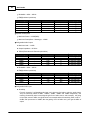
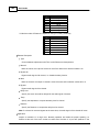
Revision History
Time
Version
2012/07/23
1.0.1
Modified DNM chapter in the
Product Features> Consoles and Accessories.
2012/07/11
1.0.0
The First Version.
Contents
3
Table of Contents
0
Introduction
10
1.1 Welcome
................................................................................................................................... 10
1.2 Ateis...................................................................................................................................
10
Presentation
1.3 EC Declaration
...................................................................................................................................
12
of Conformity
Safety Declartion
13
Quick Start
14
3.1 for IDA8
................................................................................................................................... 14
Product Features
29
4.1 IDA8 ...................................................................................................................................
29
Series Audio Processor
4.1.1 IDA8C
.......................................................................................................................................................... 30
4.1.1.1 Overview
......................................................................................................................................................... 30
4.1.1.2 Front Panel
......................................................................................................................................................... 31
4.1.1.3 Rear Panel
......................................................................................................................................................... 33
4.1.1.4 Characteristics
......................................................................................................................................................... 36
4.1.1.5 Peripherals
......................................................................................................................................................... 39
4.1.1.6 3rd Party
.........................................................................................................................................................
39
Control
4.1.2 IDA8SAB
.......................................................................................................................................................... 40
4.1.2.1 Overview
......................................................................................................................................................... 40
4.1.2.2 Front Panel
......................................................................................................................................................... 41
4.1.2.3 Rear Panel
......................................................................................................................................................... 42
4.1.2.4 Characteristics
......................................................................................................................................................... 43
4.1.2.5 Peripherals
......................................................................................................................................................... 46
4.1.2.6 3rd Party
.........................................................................................................................................................
47
Control
4.1.3 IDA8SL
.......................................................................................................................................................... 48
4.1.3.1 Overview
......................................................................................................................................................... 48
4.1.3.2 Front Panel
......................................................................................................................................................... 49
4.1.3.3 Rear Panel
......................................................................................................................................................... 50
4.1.3.4 Characteristics
......................................................................................................................................................... 51
4.1.3.5 3rd Party
.........................................................................................................................................................
54
Control
4.1.3.6 Peripherals
......................................................................................................................................................... 54
4.1.4 IDA8S
.......................................................................................................................................................... 55
4.1.4.1 Overview
......................................................................................................................................................... 55
4.1.4.2 Front Panel
......................................................................................................................................................... 56
4.1.4.3 Rear Panel
......................................................................................................................................................... 57
4.1.4.4 Characteristics
......................................................................................................................................................... 58
4.1.4.5 3rd Party
.........................................................................................................................................................
61
Control
4.1.4.6 Peripherals
......................................................................................................................................................... 61
4.1.5 Amplifier Configuration
.......................................................................................................................................................... 62
4.1.5.1 Basic Amplifier
.........................................................................................................................................................
62
Connection
4.1.5.2 Amplifier
.........................................................................................................................................................
63
Backup
4.1.6 Monitoring/Fault
.......................................................................................................................................................... 68
4.1.6.1 Table of.........................................................................................................................................................
69
System Faults
© 2012 ATEÏS
3
4
Ateis Studio
4.1.6.1 Flash Error ......................................................................................................................................... 70
4.1.6.1 I2C Error
......................................................................................................................................... 70
4.1.6.1 Net Card Error
......................................................................................................................................... 71
4.1.6.1 DSP Error
......................................................................................................................................... 71
4.1.6.1 Preset Table .........................................................................................................................................
72
Error
4.1.6.1 No Preset Error
......................................................................................................................................... 73
4.1.6.1 SPI Flash Error
......................................................................................................................................... 73
4.1.6.1 Para. Table Error
......................................................................................................................................... 74
4.1.6.1 Trans Error ......................................................................................................................................... 74
4.1.6.1 Power Error ......................................................................................................................................... 75
4.1.6.1 TEL Error
......................................................................................................................................... 76
4.1.6.1 Main FPGA Error
......................................................................................................................................... 76
4.1.6.2 Table of.........................................................................................................................................................
77
Global Faults
4.1.6.2 Normal/Backup
.........................................................................................................................................
77
Amplifier Error
4.1.6.2 Line A/B Error
......................................................................................................................................... 81
4.1.6.2 Amplifier Line
.........................................................................................................................................
85
Leakage Error
4.1.6.2 Evacuation Intput
.........................................................................................................................................
86
Error
4.1.6.2 Ateis Net Broken
......................................................................................................................................... 88
4.1.6.2 Fireman Microphone
.........................................................................................................................................
89
Error
4.1.6.2 VOX@NET Error
......................................................................................................................................... 90
4.1.6.2 User Define Error
......................................................................................................................................... 91
4.1.6.2 Remote Offline
......................................................................................................................................... 92
4.1.6.2 URGP Fault ......................................................................................................................................... 93
4.1.6.2 Remote Fault......................................................................................................................................... 94
4.1.6.3 Procedure
.........................................................................................................................................................
95
of Monitoring Setup
4.1.6.4 Zone Monitoring
......................................................................................................................................................... 96
4.1.6.5 Normal.........................................................................................................................................................
100
Amplifier Monitoring
4.1.6.6 Backup.........................................................................................................................................................
102
Amplifier Monitoring
4.1.6.7 Global .........................................................................................................................................................
106
Settings
4.1.6.8 Tone Settings
......................................................................................................................................................... 107
4.1.7 Bypass Mode
..........................................................................................................................................................
108
Paging
4.1.8 Contact I/O.......................................................................................................................................................... 109
4.1.8.1 Evacuation
.........................................................................................................................................................
109
Input
4.1.8.2 Contact.........................................................................................................................................................
110
Output
4.2 Consoles
...................................................................................................................................
111
and Accessories
4.2.1 Redundancy
..........................................................................................................................................................
111
Unit
4.2.1.1 Overview
......................................................................................................................................................... 111
4.2.1.2 Configuration
......................................................................................................................................................... 112
4.2.1.3 RU-Main
......................................................................................................................................................... 116
4.2.1.3 Overview ......................................................................................................................................... 116
4.2.1.3 Front Panel ......................................................................................................................................... 117
4.2.1.3 Rear Panel ......................................................................................................................................... 117
4.2.1.4 RU-PDC......................................................................................................................................................... 120
4.2.1.4 Overview ......................................................................................................................................... 120
4.2.1.4 Front Panel ......................................................................................................................................... 121
4.2.1.4 Rear Panel ......................................................................................................................................... 121
4.2.1.5 RU-CTL......................................................................................................................................................... 123
4.2.1.5 Overview ......................................................................................................................................... 123
4.2.1.5 Front Panel ......................................................................................................................................... 124
4.2.1.5 Rear Panel ......................................................................................................................................... 124
4.2.2 DNM
.......................................................................................................................................................... 126
4.2.2.1 Overview
......................................................................................................................................................... 126
4.2.2.2 Installation
......................................................................................................................................................... 126
4.2.2.3 Characteristics
......................................................................................................................................................... 129
© 2012 ATEÏS
Contents
5
......................................................................................................................................................... 129
4.2.2.4 Configuration
4.2.2.5 Operation
.........................................................................................................................................................
136
Notice
4.2.2.6 Two DNM
.........................................................................................................................................................
136
on the Same PDC
4.2.3 PPM AS .......................................................................................................................................................... 141
4.2.3.1 Overview
......................................................................................................................................................... 141
4.2.3.2 Control.........................................................................................................................................................
142
Panel
4.2.3.3 Characteristics
......................................................................................................................................................... 143
4.2.3.4 Configuration
......................................................................................................................................................... 144
4.2.4 PSS AS
.......................................................................................................................................................... 150
4.2.4.1 Overview
......................................................................................................................................................... 150
4.2.4.2 Control.........................................................................................................................................................
151
Panel
4.2.4.3 Characteristics
......................................................................................................................................................... 152
4.2.4.4 Configuration
......................................................................................................................................................... 153
4.2.5 URC AS
.......................................................................................................................................................... 160
4.2.5.1 Overview
......................................................................................................................................................... 160
4.2.5.2 Control.........................................................................................................................................................
161
Panel
4.2.5.3 Characteristics
......................................................................................................................................................... 161
4.2.5.4 Configuration
......................................................................................................................................................... 162
4.2.6 URGP
.......................................................................................................................................................... 167
4.2.6.1 Overview
......................................................................................................................................................... 167
4.2.6.2 Characteristics
......................................................................................................................................................... 167
4.2.6.3 Configuration
......................................................................................................................................................... 168
4.2.7 CD-Touch .......................................................................................................................................................... 169
4.2.7.1 Overview
......................................................................................................................................................... 169
4.2.7.2 Control.........................................................................................................................................................
170
Panel
4.2.7.3 Characteristics
......................................................................................................................................................... 171
4.2.8 CD8
.......................................................................................................................................................... 172
4.2.8.1 Overview
......................................................................................................................................................... 172
4.2.8.2 Control.........................................................................................................................................................
173
Panel
4.2.8.3 Characteristics
......................................................................................................................................................... 174
4.2.9 CD16
.......................................................................................................................................................... 175
4.2.9.1 Overview
......................................................................................................................................................... 175
4.2.9.2 Control.........................................................................................................................................................
176
Panel
4.2.9.3 Characteristics
......................................................................................................................................................... 178
4.2.10 Fireman Microphone
.......................................................................................................................................................... 179
4.2.10.1 Overview
......................................................................................................................................................... 179
4.2.10.2 Characteristics
......................................................................................................................................................... 179
4.2.10.3 Configuration
......................................................................................................................................................... 179
4.2.11 CDPA
.......................................................................................................................................................... 181
4.2.11.1 Overview
......................................................................................................................................................... 181
4.2.11.2 Control.........................................................................................................................................................
182
Panel
4.2.11.3 Characteristics
......................................................................................................................................................... 184
4.2.12 PCP
.......................................................................................................................................................... 185
4.2.12.1 Overview
......................................................................................................................................................... 185
4.2.12.2 Control.........................................................................................................................................................
186
Panel
4.2.12.3 Characteristics
......................................................................................................................................................... 188
4.2.13 PSC
.......................................................................................................................................................... 189
4.2.13.1 Overview
......................................................................................................................................................... 189
4.2.13.2 Characteristics
......................................................................................................................................................... 190
4.2.14 URC200 TPC
.......................................................................................................................................................... 191
4.2.14.1 Overview
......................................................................................................................................................... 191
4.2.14.2 Control.........................................................................................................................................................
192
Panel
4.2.14.3 Characteristic
......................................................................................................................................................... 192
4.2.14.4 Configuration
......................................................................................................................................................... 193
© 2012 ATEÏS
5
6
Ateis Studio
193
4.2.14.4 Edit Control .........................................................................................................................................
Items
4.2.14.4 Import/Export
.........................................................................................................................................
198
Configuration
4.2.14.4 Save/Load Configuration
......................................................................................................................................... 198
4.2.14.4 Reset Configuation
......................................................................................................................................... 198
4.2.14.5 Device .........................................................................................................................................................
199
Maintenance
4.2.14.5 Update Firmware
......................................................................................................................................... 199
4.2.14.5 Protected Mode
......................................................................................................................................... 202
4.2.15 PPM-IT5 .......................................................................................................................................................... 204
4.2.15.1 Overview
......................................................................................................................................................... 204
4.3 Amplifier
................................................................................................................................... 205
4.3.1 SPA
.......................................................................................................................................................... 205
4.3.1.1 Overview
......................................................................................................................................................... 205
4.3.1.2 Front Panel
......................................................................................................................................................... 207
4.3.1.3 Rear Panel
......................................................................................................................................................... 208
4.3.1.4 Characteristics
......................................................................................................................................................... 209
4.4 Optional
...................................................................................................................................
0
Boards
4.4.1
.......................................................................................................................................................... 0
Network Boards
System Functionality
211
5.1 Ateis
...................................................................................................................................
211
Studio
211
Overiew of..........................................................................................................................................................
Ateis Studio
.......................................................................................................................................................... 212
System Requirement
..........................................................................................................................................................
213
Install Ateis
Studio
.......................................................................................................................................................... 218
Windows Layout
.......................................................................................................................................................... 219
File
.......................................................................................................................................................... 220
Edit
.......................................................................................................................................................... 221
View
Geometry .......................................................................................................................................................... 222
..........................................................................................................................................................
225
Comoponent
Editing
.......................................................................................................................................................... 232
Tools
Operation .......................................................................................................................................................... 235
Window .......................................................................................................................................................... 236
.......................................................................................................................................................... 238
Help
238
Component..........................................................................................................................................................
Template
.......................................................................................................................................................... 240
Resource Manager
Object Tree.......................................................................................................................................................... 241
.......................................................................................................................................................... 241
Layers
Bird's Eye .......................................................................................................................................................... 242
Properties .......................................................................................................................................................... 243
.......................................................................................................................................................... 244
Message Library
.......................................................................................................................................................... 245
Logo Library
5.2 Presets
................................................................................................................................... 245
5.1.1
5.1.2
5.1.3
5.1.4
5.1.5
5.1.6
5.1.7
5.1.8
5.1.9
5.1.10
5.1.11
5.1.12
5.1.13
5.1.14
5.1.15
5.1.16
5.1.17
5.1.18
5.1.19
5.1.20
5.1.21
Overview .......................................................................................................................................................... 245
.......................................................................................................................................................... 246
Master Presets
.......................................................................................................................................................... 248
Sub-Presets
5.3 Event
...................................................................................................................................
251
Management
5.2.1
5.2.2
5.2.3
5.3.1
5.3.2
5.3.3
5.3.4
5.3.5
5.3.6
.......................................................................................................................................................... 251
Event Manager
..........................................................................................................................................................
252
Value Trigger
Event
..........................................................................................................................................................
254
Value Control
Event
..........................................................................................................................................................
257
Step Trigger
Event
..........................................................................................................................................................
259
Step Control
Event
..........................................................................................................................................................
261
Master Preset
Change Change
© 2012 ATEÏS
Contents
7
262
Sub-Preset..........................................................................................................................................................
Change Evnet
..........................................................................................................................................................
263
Intergration Paging Event
..........................................................................................................................................................
263
Singular Paging
Event
5.4 Device
...................................................................................................................................
263
Management
5.3.7
5.3.8
5.3.9
263
Search and..........................................................................................................................................................
Settings
.......................................................................................................................................................... 265
Read Version
.......................................................................................................................................................... 265
Update Firmware
.......................................................................................................................................................... 268
Ateis Net Deploying
.......................................................................................................................................................... 268
Remote Plugin
Reverse .......................................................................................................................................................... 270
5.5 3rd ...................................................................................................................................
270
Party Control
5.4.1
5.4.2
5.4.3
5.4.4
5.4.5
5.4.6
5.5.1 Ateis 3rd Party
..........................................................................................................................................................
270
Control
5.5.1.1 Overview
......................................................................................................................................................... 270
5.5.1.2 Assign .........................................................................................................................................................
270
Elements to 3rd Party Control
5.5.1.3 3rd Party
.........................................................................................................................................................
271
Control List
5.5.1.4 3rd Party
.........................................................................................................................................................
271
Control Command
5.5.2 Modbus Control
.......................................................................................................................................................... 0
5.6 User
...................................................................................................................................
272
Management
Overview .......................................................................................................................................................... 272
.......................................................................................................................................................... 273
User Levels
.......................................................................................................................................................... 274
User Accounts
5.7 Compile
................................................................................................................................... 0
5.6.1
5.6.2
5.6.3
5.8 Store ................................................................................................................................... 0
5.9 Save ...................................................................................................................................
0
Parameters
5.10 Online/Offline
................................................................................................................................... 0
5.11 Audio...................................................................................................................................
0
Enable/Disable
Components of Audio Processor
275
6.1 AEC................................................................................................................................... 275
.......................................................................................................................................................... 275
Parameters
Functions .......................................................................................................................................................... 277
6.2 Delay
...................................................................................................................................
280
(Advanced)
6.1.1
6.1.2
6.3 Delay
...................................................................................................................................
284
(Basic)
6.4 Dynamic
................................................................................................................................... 287
6.4.1 AGC\AGC Stereo
.......................................................................................................................................................... 287
6.4.2 Auto Noise..........................................................................................................................................................
291
Gain (A.N.G)
6.4.3 Compressor\Compressor
..........................................................................................................................................................
299
Stereo
6.4.4 Comp-limiter
.......................................................................................................................................................... 303
6.4.5 DNM
.......................................................................................................................................................... 306
6.4.6 Ducker\Ducker
..........................................................................................................................................................
310
Stereo
6.4.7 Expander\Expander
..........................................................................................................................................................
313
Stereo
6.4.8 Gate
.......................................................................................................................................................... 316
6.4.8.1 Gate - Mono
......................................................................................................................................................... 316
6.4.8.2 Gate - Stereo
......................................................................................................................................................... 318
6.4.8.3 Gate - Voice
......................................................................................................................................................... 321
6.4.8.4 Gate with
.........................................................................................................................................................
323
Sidechain
6.4.9 Limiter\Limiter
..........................................................................................................................................................
326
Stereo
6.5 Equalizer
................................................................................................................................... 329
6.5.1
.......................................................................................................................................................... 329
GEQ\GEQ Stereo
© 2012 ATEÏS
7
8
Ateis Studio
.......................................................................................................................................................... 332
PEQ\PEQ Stereo
6.6 Feedback
................................................................................................................................... 335
6.5.2
6.7 Filter
................................................................................................................................... 338
.......................................................................................................................................................... 338
All Pass Filter
Band Pass.......................................................................................................................................................... 340
Band Stop .......................................................................................................................................................... 343
..........................................................................................................................................................
346
Crossover/Crossover
Stereo
Hi/Lo Pass.......................................................................................................................................................... 349
Notch Filter.......................................................................................................................................................... 351
.......................................................................................................................................................... 354
Shelving Filter
6.8 Fireman
................................................................................................................................... 356
6.7.1
6.7.2
6.7.3
6.7.4
6.7.5
6.7.6
6.7.7
6.9 Input
................................................................................................................................... 357
.......................................................................................................................................................... 357
Input
Mono Input.......................................................................................................................................................... 360
.......................................................................................................................................................... 362
Stereo Input
.......................................................................................................................................................... 364
Duplex Input
Inverter .......................................................................................................................................................... 366
6.10 Level
...................................................................................................................................
367
Controller
6.9.1
6.9.2
6.9.3
6.9.4
6.9.5
6.11 Local
...................................................................................................................................
369
Echo Suppressor
6.12 Logic
................................................................................................................................... 371
6.12.1 AND
.......................................................................................................................................................... 371
6.12.2 EVAC Board
.......................................................................................................................................................... 372
6.12.3 Evacution Input
.......................................................................................................................................................... 374
6.12.4 Event
.......................................................................................................................................................... 375
6.12.4.1 Trigger......................................................................................................................................................... 376
6.12.5 Logic Control
.......................................................................................................................................................... 378
6.12.6 Logic Meter
.......................................................................................................................................................... 379
6.12.7 Logic Net Input
.......................................................................................................................................................... 380
6.12.8 Logic Net Output
.......................................................................................................................................................... 381
6.12.9 NOT
.......................................................................................................................................................... 382
6.12.10 OR
.......................................................................................................................................................... 382
6.12.11 Output
.......................................................................................................................................................... 383
6.12.12 Scheduler .......................................................................................................................................................... 384
6.13 Meter
................................................................................................................................... 388
388
Peak/RMS ..........................................................................................................................................................
Meter
6.14 Message
................................................................................................................................... 390
6.13.1
.......................................................................................................................................................... 390
Message Player
MM Player.......................................................................................................................................................... 391
6.15 Mixer
................................................................................................................................... 392
6.14.1
6.14.2
AutoMixer .......................................................................................................................................................... 392
395
AutoMixer ..........................................................................................................................................................
MM
.......................................................................................................................................................... 399
Matrix
Standard .......................................................................................................................................................... 401
6.16 Net ...................................................................................................................................
402
Input
6.15.1
6.15.2
6.15.3
6.15.4
6.17 Net ...................................................................................................................................
404
Output
6.18 Noise
...................................................................................................................................
405
Generator
6.18.1
6.18.2
6.18.3
Pink
Tone
White
.......................................................................................................................................................... 405
.......................................................................................................................................................... 406
.......................................................................................................................................................... 408
© 2012 ATEÏS
Contents
9
................................................................................................................................... 409
6.19 Output
.......................................................................................................................................................... 409
Output
.......................................................................................................................................................... 411
Monitor Output
.......................................................................................................................................................... 413
Mono Output
.......................................................................................................................................................... 415
Stereo Output
.......................................................................................................................................................... 417
Duplex Output
6.20 Page
...................................................................................................................................
419
Control
6.19.1
6.19.2
6.19.3
6.19.4
6.19.5
.......................................................................................................................................................... 419
S/W Page Control
.......................................................................................................................................................... 421
Network Paging
6.21 Recorder
................................................................................................................................... 0
6.20.1
6.20.2
6.22 RS485
...................................................................................................................................
432
Audio
.......................................................................................................................................................... 432
RS485 Input
.......................................................................................................................................................... 434
RS485 Output
6.23 Selector
................................................................................................................................... 436
6.22.1
6.22.2
6.24 Signal
...................................................................................................................................
437
Monitor
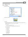
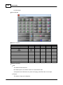
6.25 Telephone
...................................................................................................................................
439
Card
.......................................................................................................................................................... 439
TC Transmit
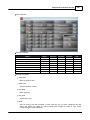
TC Receive.......................................................................................................................................................... 442
6.26 VOIP ................................................................................................................................... 0
6.25.1
6.25.2
6.27 Voxnet
...................................................................................................................................
444
Control
Contact Infomation
Index
445
0
© 2012 ATEÏS
9
10
Ateis Studio
1
Introduction
1.1
Welcome
Thank you for choosing ATEÏS. We here at ATEÏS hope you will enjoy our technology as much as we
enjoyed developing and building it.
This manual is intended to provide the user with the necessary understanding of our system architecture
as well as guide users through the configuration process.
This manual can be updated at any time without prior notice in order to keep it up to date.
If you find errors in this manual or would like to improve on the presentation, feel free to submit mistakes,
suggestions or questions by sending an email.
We hope that this Help File Manual will provide you all the information you need. However if you have
any questions, feel free to contact us.
1.2
Ateis Presentation
ATEÏS has been in the professional audio market for close to thirty years and is viewed as a leading
competitor in the Public Address, Voice Alarm, and Professional Audio Market in Europe, Asia, and the
Middle East.
Products
The company offers a full range of audio equipment: microphones, preamplifiers, digital processors,
digital audio matrixes, loud-speaker monitoring systems, amplifiers, etc. ATEÏS designs and
manufactures leading products in the voice alarm systems market which have been certified EN60849
compliant by the TÜV and UL listed.
Development
Thanks to a development team of over forty engineers and a close connection to our customer base,
we are able to respond rapidly to the demands of our various vertical markets with specific solutions
and cutting edge technology. You can rest assured that our technology is always cutting edge with a
view to the future.
ATEÏS Vertical Markets
Transportation (Railways, Subways, Airports)
High rise buildings
© 2012 ATEÏS
Introduction
Hotels
Restaurants
Shopping malls
Theme parks
Places of worship
Stadia
Museums
Industrial
University and campus applications
© 2012 ATEÏS
11
12
1.3
Ateis Studio
EC Declaration of Conformity
© 2012 ATEÏS
Safety Declartion
2
13
Safety Declartion
Do not expose the device to extreme temperatures, direct sunlight, humidity, or dust, which could
cause fire or electrical shock hazard.
Keep away water or other liquids from the device. Otherwise fire or electrical shock may result.
Connect the power cord only to an AC outlet of the type stated in this Owner's Manual or as marked
on the unit. Otherwise fire and electrical shock hazard results.
When disconnecting the power cord from an AC outlet always grab the plug. Never pull the cord. A
damaged power cord is a potential risk of fire and electrical shock hazard.
Avoid touching power plugs with wet hands. Doing so is a potential electrical shock hazard.
Take care for correct polarity when operating the device from a DC power source. Reversed polarity
may cause damage to the unit or the batteries.
Avoid placing heavy objects on power cords. A damaged power cord is a fire and electrical shock
hazard.
Do not cut, scratch, bend, twist, pull, or heat the power cord. A damaged power cord is a fire and
electrical shock hazard. Ask your ATEÏS dealer for replacement.
Turn off immediately the unit, remove the power cord from the AC outlet and consult your ATEÏS dealer
in any of the following circumstances:
Smoke, odor, or noise getting out of the unit.
Foreign objects or liquids get inside the device.
The unit has been dropped or the shell is damaged.
The power cord is damaged.
If you continue using the device, fire and electrical shock may result.
Do not drop or insert metallic objects or flammable materials into the unit as this may result in fire and
electrical shock.
Do not remove the device's cover, as there are exposed parts inside carrying high voltages that may
cause an electrical shock. Contact your ATEÏS dealer if internal inspection, maintenance, or repair is
necessary.
Do not try to make any modifications to the device. This is a potential fire and electrical shock hazard.
Avoid the device's ventilation slots to be blocked. Blocking the ventilation slots is a potential fire
hazard.
© 2012 ATEÏS
14
Ateis Studio
To prevent the unit from falling down and causing personal injury and/or property damage, avoid
installing or mounting the unit in unstable locations.
Leave enough space above and below the unit to provide good ventilation of the device. If the airflow is
not adequate, the device will heat up inside and may cause a fire.
Operate the device in an environment with a free-air temperature of between 0 °C and 40 °C (32 °F and
104 °F).
Turn off all audio equipment when making any connections to the device, and make sure to use
adequate cables.
Do not use benzene, thinner, or chemicals to clean the device. Use only a soft, dry cloth.
If the device is moved from a cold place (e.g., overnight in a car) to a warmer environment,
condensation may form inside the unit, which may affect performance. Allow the device to acclimatize
for about one hour before use.
3
Quick Start
3.1
for IDA8
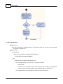
Here is a simple demonstration showing how to configure one of our platforms and how to adjust
parameters to get a 2K tone from the connected speaker. This example uses an IDA8C, but the other
audio processors follow the same procedure.
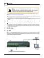
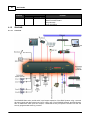
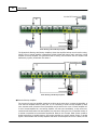
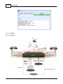
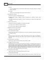
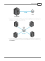
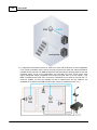
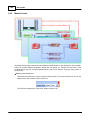
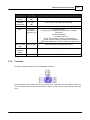
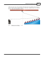
1. Setup device and wiring
Speaker is connect to Amplifier Zone Output(Zone1).
© 2012 ATEÏS
Quick Start
15
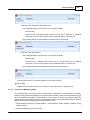
Connect ethernet wire for device and PC.IDA8C.
2. Power up device
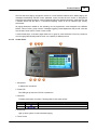
Power up device and make sure power LED is on.
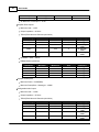
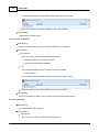
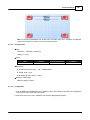
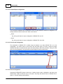
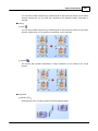
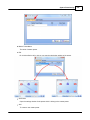
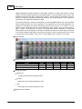
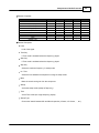
3. Set IP, Subnet mask and gateway address of device
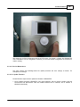
To set IP, Subnet mask and Gateway address, use the menu on the touch screen on the front of the
IDA8C. If you are using a platform that does not have a touch screen, use the other method to
setup, see the related topics of it. In this case, set IP = 192.168.100.79.
The subnet mask and geteway address should be the same as computer's.
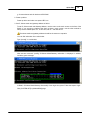
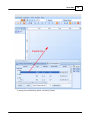
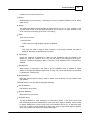
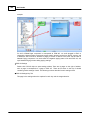
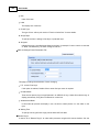
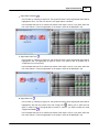
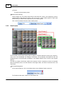
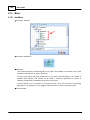
You can find information from cmd window:
Type "ipconfig" in cmd window:
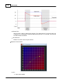
After execute command "ipconfig" IP/Subnet Mask/Gateway information is displayed in window,
inside the green rectangle:
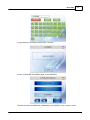
In IDA8C, IP/Subnet Mask/Gateway allow modify if user login the system. Follow the steps to login:
Click [SYSTEM SET] in [MAIN MENU] page:
© 2012 ATEÏS
16
Ateis Studio
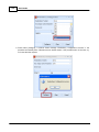
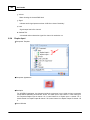
Click [LOGIN] in [SYSTEM SET MENU-1] page:
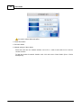
Click [USER NAME] in [LOGIN] page:
Input ID "ADMIN" which is the default user of IDA8C. Remain the blank of password.
© 2012 ATEÏS
Quick Start
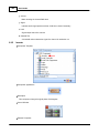
A page showing the message to prompt login is success:
Go back to [SYSTEM SET MENU-2] page, click [ETHERNET]
There are three field: [IP ADDRESS], [SUBMASK] and [GATEWAY]. Click for each to setup.
© 2012 ATEÏS
17
18
Ateis Studio
You need to reboot device take effect.
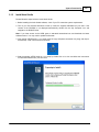
4. Install Ateis Studio
5. Run Ateis Studio
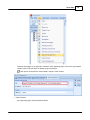
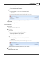
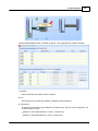
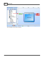
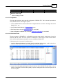
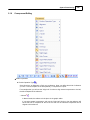
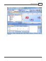
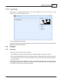
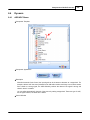
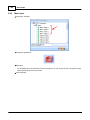
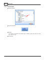
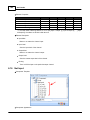
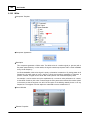
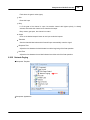
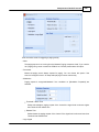
6. Network settings of Ateis Studio
If there are more than one network interface card on PC, it need to select which one is used to
connect to device.
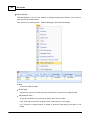
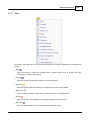
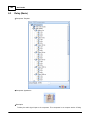
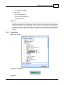
To open the window for network interface card, click main menu of Ateis Studio [View > Device
Management]
© 2012 ATEÏS
Quick Start
19
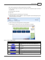
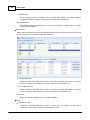
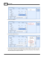
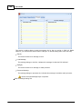
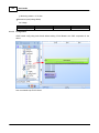
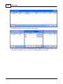
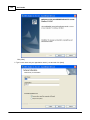
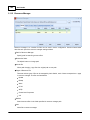
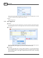
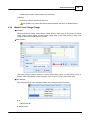
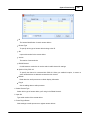
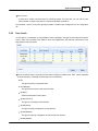
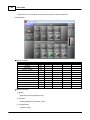
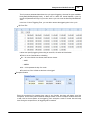
There are three pages on the right side of window, select [Network] page. Choose the right network
interface card on NIC field which is labeled using red rectangle.
If UDP port is conflict with the other software, change to other number.
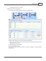
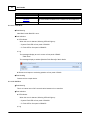
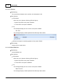
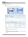
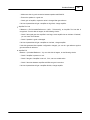
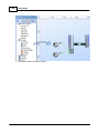
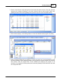
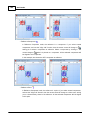
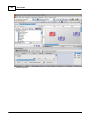
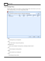
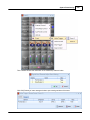
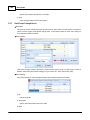
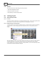
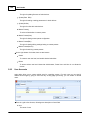
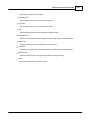
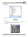
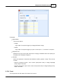
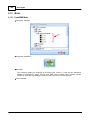
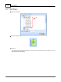
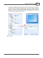
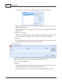
7. Search devices
Go to [Devices] page, and press [Search] button:
© 2012 ATEÏS
20
Ateis Studio
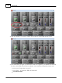
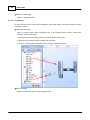
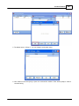
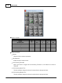
After few seconds, devices are listed by tree structure on [Devices] field, IP address of the device we
want to config is 192.168.100.79.
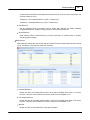
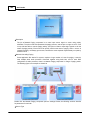
8. Connect to device
Click [Connect] link to open menu of IDA8C:
© 2012 ATEÏS
Quick Start
21
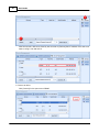
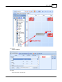
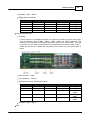
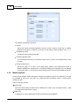
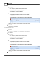
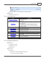
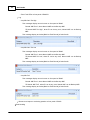
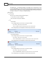
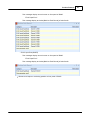
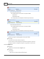
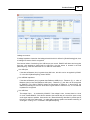
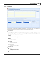
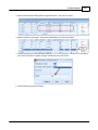
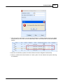
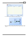
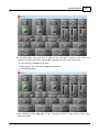
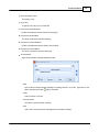
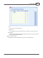
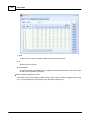
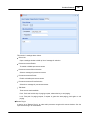
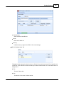
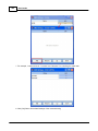
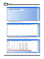
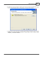
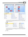
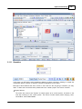
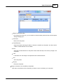
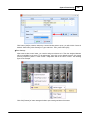
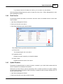
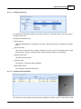
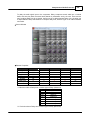
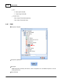
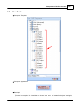
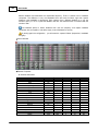
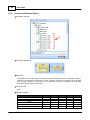
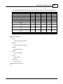
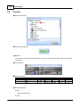
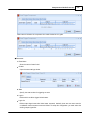
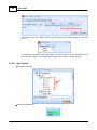
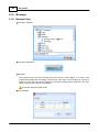
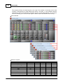
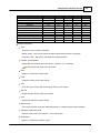
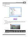
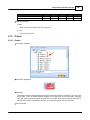
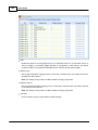
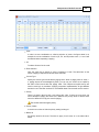
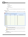
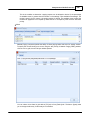
9. Check compatibility between device and Ateis Studio. Click [Read Version] of menu.
A window [Version] opened, press button [Read], And then information about version is display in
the grid:
If all firmware unit are compatible with Ateis Studio, go to step 11, otherwise step 10. The below
figure is an example of incompatible version of firmware unit See the red rectangle.
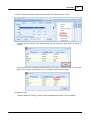
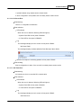
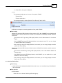
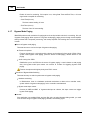
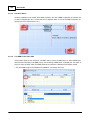
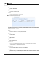
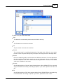
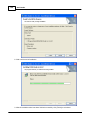
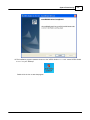
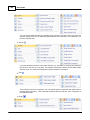
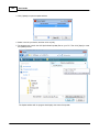
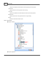
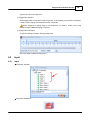
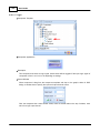
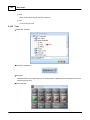
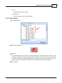
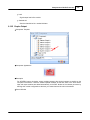
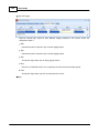
10.Update firmware
Close the window of [Version], go back to [Device Management] window, click link [Update]:
© 2012 ATEÏS
22
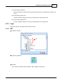
Ateis Studio
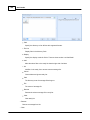
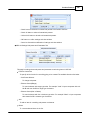
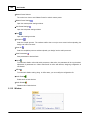
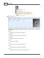
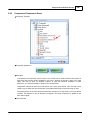
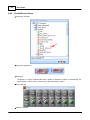
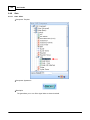
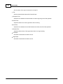
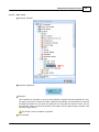
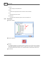
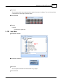
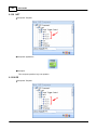
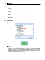
A window [Device Select] opened allow the target IDA8 be selected, click button [OK]:
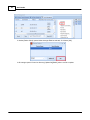
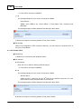
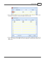
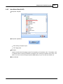
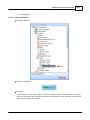
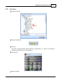
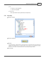
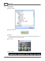
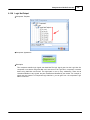
A file manager opened. Goes into directory [Update file][IDA8C] select .asu file to update.
© 2012 ATEÏS
Quick Start
23
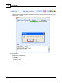
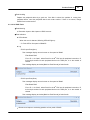
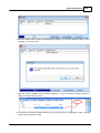
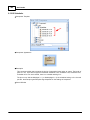
Then, the update process start, and pop a window after update file is transferred to device, click
[Yes] to restart device.
© 2012 ATEÏS
24
Ateis Studio
todo
Eng ver
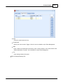
Check device version using step 9 again, the version should become compatible this time, if version
is compatible, go to step 11.
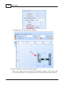
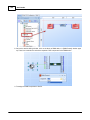
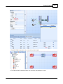
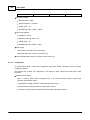
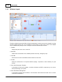
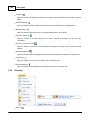
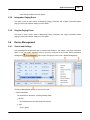
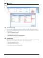
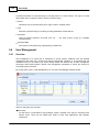
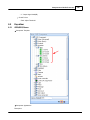
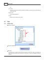
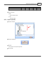
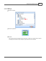
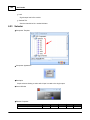
11.Create a New file
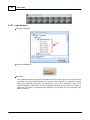
Create a new file by clicking the button on left top of Ateis Studio, marked as red rectangle.
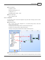
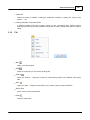
12.Create a IDA8C block in device editor window
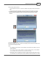
Drag the row in [Device Management] window and drop it in device editor window:
© 2012 ATEÏS
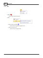
Quick Start
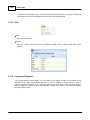
A window [Set Audio Module] opened, click button [Create].
© 2012 ATEÏS
25
26
Ateis Studio
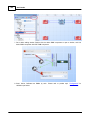
Then a IDA8C block is created for further configuration.
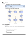
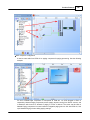
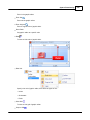
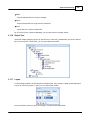
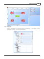
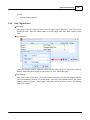
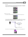
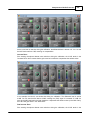
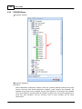
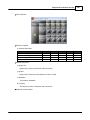
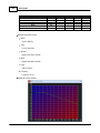
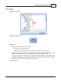
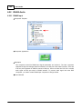
13.Add Tone component and connect to Output component
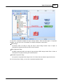
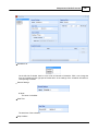
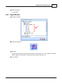
Double click on IDA8C block to open [IDA8C DSP Configuration - IDA8C1], In this windows, allow
you to edit dsp configuration, let's do a simple setup use a Tone Generator and Output component:
© 2012 ATEÏS
Quick Start
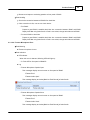
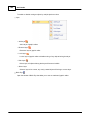
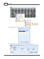
14.Connect
Connect to device.
15.Store
Click store button on tools bar.
© 2012 ATEÏS
27
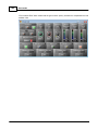
28
Ateis Studio
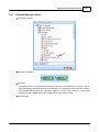
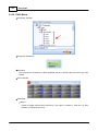
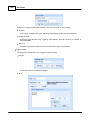
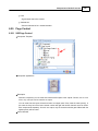
A window [Store] is opened and store process start, during the process, system will ask user to turn
on or off audio, click Yes.
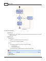
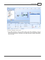
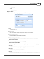
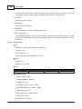
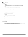
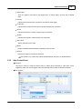
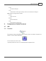
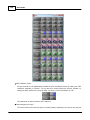
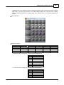
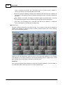
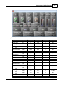
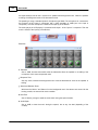
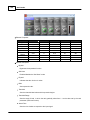
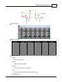
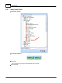
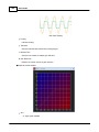
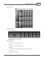
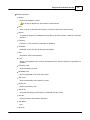
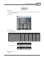
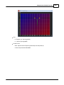
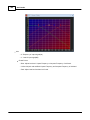
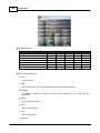
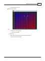
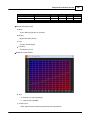
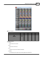
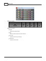
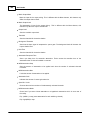
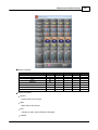
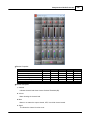
16.Adjust element
Set element of Tone Generator:
Level(dB) = -10
Tone Button = On
Tone freq.(Hz) = 2.00k
© 2012 ATEÏS
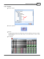
Quick Start
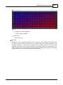
29
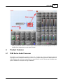
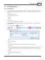
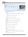
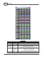
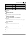
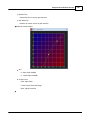
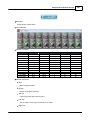
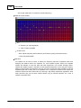
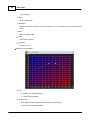
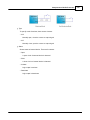
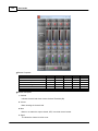
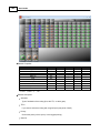
Now you should see channel 1 meter as figure shown and hear a 2k tone from speaker connect to
Amplifier Zone Output(zone1) on rear panel of IDA8C.
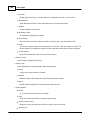
4
Product Features
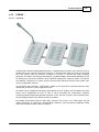
4.1
IDA8 Series Audio Processor
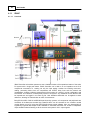
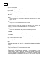
The IDA8 is a third generation modular system that complies with current architectural demands
requiring IP-and/or Fiberoptics Networking to cover for any complex design possible. IDA8 responds to
Public Address and Voice Alarm requirements as stated in EN 54-16, ISO 7240-16 and BS 5839/8, with
specific attributes for compliance in large installations.
© 2012 ATEÏS
30
Ateis Studio
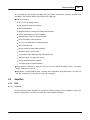
4.1.1
IDA8C
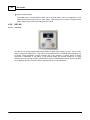
4.1.1.1
Overview
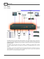
IDA8C Controller unit enables operators to see a detailed overview of the operational status of the entire
PA system with a single push button. IDA8C Controller unit is able to run an impedance scan of all
components connected to it, covering not only the input paging consoles but including connectors,
cabling, processing blocks such as compressors and limiters, delay lines and the network and
loudspeakers. It stores a reference measurement of the system as it exists in a given configuration and
environment. This reference is subsequently stored in the system. Any alterations to this reference will
be reported and are logged in an event log file. User definable thresholds can be applied to these
references, allowing for customization to match circumstances.
Being EN 54-16/ISO 7240-16 and BS 5839 part 8 security systems, all components and peripherals are
monitored. All incidents are recorded into a data file which can be consulted on the controller module
monitor display or on a PC using the ATEÏS Studio remote control software. Also, any detected fault is
signalled by a general fault output contact available on the IDA8C Controller unit. A built-in loudspeaker
output enables selective listening to all the sources and system’s 100 V output signals.
© 2012 ATEÏS
Product Features
31
IDA8C Controller unit is easily configured with our PC based ATEÏS-Studio global software (Windows
compatible). Software access can be password protected. Once programmed, the system will be able to
work independently(off-line) without the need of a PC to be connected.
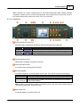
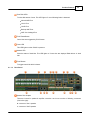
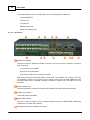
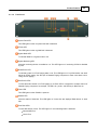
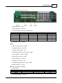
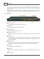
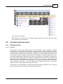
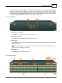
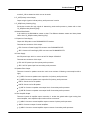
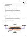
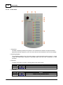
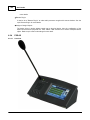
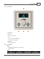
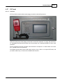
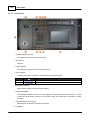
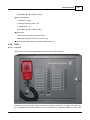
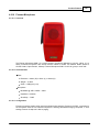
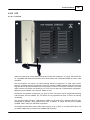
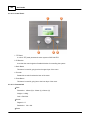
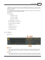
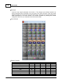
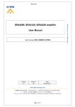
4.1.1.2
Front Panel
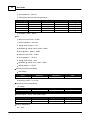
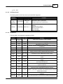
Fireman Microphone Active LED
Show the activity of the fireman microphone, there are two states of this LED: test
Status
Permanent
Blinking
Blinking
Frequency
°
°
°
°°°
°
Activity
Active, Fireman microphone is allowed to paging.
Zones are busy, fireman microphone is not allowed to paging.
Pre chime is playing.
Fireman Microphone Input
DIN Connector for fireman microphone connection.
Fireman Microphone Hook
An U-shape hook to place fireman microphone.
Monitoring Speaker
The IDA8C integrates a monitoring speaker in front panel. There are two functions of this speaker
Function
Warning Tone
Activity
A buzzer sound is generated when some faults is detected in system.
Monitor audio sources of IDA8C. The source to be monitored can be selected
Source Monitoring
via Ateis Studio software.
Note: If a fault is detected when speaker is monitoring source, then the source monitoring will be
interrupted and play buzzer sound for the fault.
Bypass Mode LED
To indicate IDA8C is in bypass mode or not.
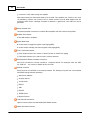
© 2012 ATEÏS
32
Ateis Studio
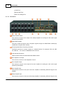
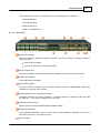
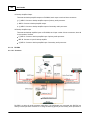
G.Fault LED
This LED lights on when a global fault is detected.
Note: Fault LED and system fault LED are exclusive, if system fault and global fault are detected at
the same time, system only light the system fault LED.
System Fault LED
This LED lights on when a system fault fault is detected.
Global EVAC LED
To indicate system is in EVAC paging or not. This LED lights on if any IDA8 device over Ateis Net
do an EVAC paging.
Bypass Monitoring LED
Show the monitoring function is enabled or not. This LED lights on if monitoring of IDA8 is disabled
by user.
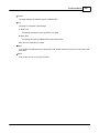
Touch Screen
3.5" Color touch panel offer a graphical interface for user to control or read the status of system.
There is a multi layered menu on it to get/set parameters or change settings of device.
ESC Button
To Navigate menu of touch screen.
OK Button
To Navigate menu of touch screen.
Up Button
To Navigate menu of touch screen.
Down Button
To Navigate menu of touch screen.
Plus Button
To Navigate menu of touch screen.
Down Button
To Navigate menu of touch screen.
Zone EVAC LEDs
To show the audio channel is in EVAC paging or not. Each LED is correspond to a output channel of
Network Paging component, for example, 1st LED is for pin M1, 2nd LED for pin M2 and so on.
© 2012 ATEÏS
Product Features
33
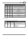
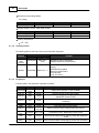
Zone Fault LEDs
To show fault status of zone. This LED light on if one of following faults is detected:
Normal AMP Error
Line A Error
Line B Error
Backup AMP Error
AMP Line Leakage Error
EVAC Reset Button
Cancel the event triggered by EVAC button.
Power LED
This LED lights on when IDA8C is power on.
Network LED
Show the status of Ateis Net. This LED lights on if more than two deployed IDA8 devices in Ateis
Net.
EVAC Button
To trigger event bind with this button.
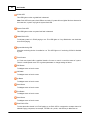
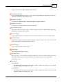
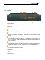
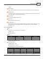
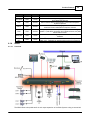
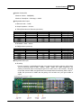
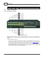
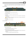
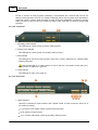
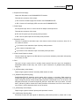
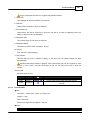
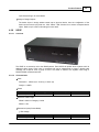
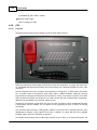
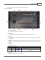
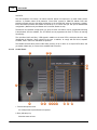
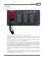
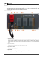
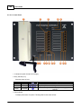
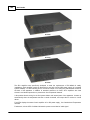
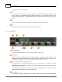
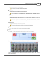
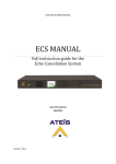
4.1.1.3
Rear Panel
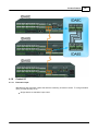
Speaker Zone Outputs
There are 8 zones for speaker & amplifier connection. each zone consists of following connectors
(from left to right):
connector of line A speaker
connector of line B speaker
© 2012 ATEÏS
34
Ateis Studio
connector of 100V audio coming from amplifier
IDA8 output exactly the same audio signal to line A and B. Two speakers can connect to one zone
for redundancy purpose, one connect to line A, another connect to line B. Both speaker lines are
monitored, that's mean if a damage of speaker is detected, a global fault "Line A/B Error" will be
generated.
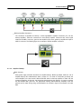
Backup Amplifier I/Os
Two backup amplifier connectors included 0 dB to amplifiers and 100V return from amplifiers.
Amplifier Zone Outputs
8 Zone 0dB output to amplifiers.
Bypass Mode Input
Contact input to engage the bypass mode paging(CMD).
Contact output to display the state of bypass mode paging(ACK).
EVAC, Fault State Outputs
EVAC Output Contact: this contact is closed if system is under EVAC paging.
Fault Output Contact: this contact is open if a fault is detected.
PDC(Peripherals Device Controller) Connectors
Four RJ-45 connectors to connect consoles or peripheral devices. For examples, PSS AS, URC
AS, PPM AS, ... are connect to IDA8C via this connector.
Ethernet Connector
RJ-45 connector to link IDA8C on an ethernet network. The following end points are communicated
with IDA8C through ethernet networking.
Ateis Studio software
3rd party devices
Voxnet Server
PMIP-D
VNB
PPM-IT5
TERRA Devics
Modbus Protocol
Local Ateis Net Connectors
Optional card to build a local dedicated IDA8C-IDA8S network.
Global Ateis Net Connectors
© 2012 ATEÏS
Product Features
35
Optional card to build a global dedicated IDA8C network.
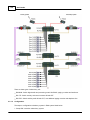
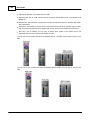
Configurable Audio I/Os
Two configurable 0dB audio I/O port A and B. Each port is available to assemble an audio card.
There are 4 channels on each audio I/O card.
Telephone Line Input
A connector for telephone signal coming from telephone company.(optional).
Telephone Connector
A connector for external telephone connection.(optional).
Bypass Mode Outputs
This port to share the bypass mode microphone signals through the IDA8C-IDA8S network(only
needed when using fiber optic network).
Contact Outputs
8 logic outputs channels to close/open circuit for an external device, this contact is normally open.
Evacuation Inputs
9 evacuation contact inputs that allow the monitoring of external contact. They also can be used in
UGA mode, trigger by a voltage polarization change.
24V DC Output
This connector supplies a 24VDC source.
24V DC Input
Main 24VDC power supply connector.
AC Power Socket
Main 110~240 V 1.2A, 47~63Hz AC power input with fuse. If 24V DC and AC power input at the
same time, IDA8C will use AC power, and switch to DC power if there is no AC power input.
Fuse Rating: 3.15A
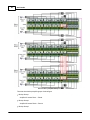
Zone Boards
Zone Board1
The following I/Os are belong to zone board1 in IDA8C: speaker zone output ch1~ch4, backup
amplifier1, amplifier zone output ch1 ~ ch4.
Zone Board2
The following I/Os are belong to zone board2 in IDA8C: speaker zone output ch5~ch8, backup
amplifier2, amplifier zone output ch5 ~ ch8.
© 2012 ATEÏS
36
Ateis Studio
4.1.1.4
Characteristics
Case
Dimension = 436mm (W) x 313mm (L) x 88mm (H).
Weight = 5.36Kg.
Color = RAL7016.
Screen
3.5" Color touch panel.
Power
Item
AC Input
DC Input
DC Output
Voltage
Current Consumption
Comment
100V~240V
1.6A@100V, 0.7A@240V Frequency:47Hz~63Hz
18V~26V, Typical 24V
2A
18V~26V, Typical 24V
0.5A
-
AC Maximum Consumption = 45 W.
Amplifier Zone Outputs
Maximum level = 14 dB
Output Impedance = 50 Ohm
THD+N(Total Harmonic Distortion plus Noise)
Sensitivity
0dBu
-12dBu
-24dBu
-40dBu
-54dBu
Minimum
-
Maximum
0.04
0.06
0.06
0.06
0.06
Unit
%
%
%
%
%
Frequency
20~20kHz@+4dBu
20~20kHz@-2dBu
20~20kHz@-14dBu
20~20kHz@-30dBu
20~20kHz@-44dBu
Maximum
-81
-93
-104
-112
-115
Unit
dBu
dBu
dBu
dBu
dBu
Frequency
20~20kHz@150Ù
20~20kHz@150Ù
20~20kHz@150Ù
20~20kHz@150Ù
20~20kHz@150Ù
Bandwidth = 20Hz ~ 20kHz.
EIN(Equivalent Input Noise)
Sensitivity
0dBu
-12dBu
-24dBu
-40dBu
-54dBu
Minimum
-
Speaker line/Amplifier
Maximum Power = 700W(RMS).
Maximum Power(Siren + Message) = 1000W.
Monitoring Speaker
Impedance = 8 Ohm.
Maximum Power @ 1kHz = 1.6W.
© 2012 ATEÏS
Product Features
37
THD @ 1kHz = < 1%.
Bandwidth @ -3dB = 100Hz ~ 12kHz.
Configurable Audio Output
Maximum level = 14 dBu
Output Impedance = 50 Ohm
THD+N(Total Harmonic Distortion plus Noise)
Sensitivity
0dBu
-12dBu
-24dBu
-40dBu
-54dBu
Minimum
-
Maximum
0.04
0.06
0.06
0.06
0.06
Unit
%
%
%
%
%
Frequency
20~20kHz@+4dBu
20~20kHz@-2dBu
20~20kHz@-14dBu
20~20kHz@-30dBu
20~20kHz@-44dBu
Maximum
-81
-93
-104
-112
-115
Unit
dBu
dBu
dBu
dBu
dBu
Frequency
20~20kHz@150Ù
20~20kHz@150Ù
20~20kHz@150Ù
20~20kHz@150Ù
20~20kHz@150Ù
Bandwidth = 20Hz ~ 20kHz.
EIN(Equivalent Input Noise)
Sensitivity
0dBu
-12dBu
-24dBu
-40dBu
-54dBu
Minimum
-
Configurable Audio Input
Sensitivity
For each channel of configurable audio input card, there are five levels to gain the audio signal.
They are sensitivity values of 0dBu, -12dbBu, -24dBu, -40dBu and -54dBu respectively. The
meaning of sensitivity value is how large the gain for an audio source, and to amplify the giving
minus input source to 0dBu, the figure below is an example when the sensitivity value is set to 54dBu, and input source is -54dBu, after the gaining circuit of audio card, you'll get the 0dBu of
output.
Maximum level = 14 dBu
© 2012 ATEÏS
38
Ateis Studio
Input Impedance = 10k Ohm
THD+N(Total Harmonic Distortion plus Noise)
Sensitivity
0dBu
-12dBu
-24dBu
-40dBu
-54dBu
Minimum
-
Maximum
0.04
0.06
0.06
0.06
0.06
Unit
%
%
%
%
%
Frequency
20~20kHz@+4dBu
20~20kHz@-2dBu
20~20kHz@-14dBu
20~20kHz@-30dBu
20~20kHz@-44dBu
Bandwidth = 20Hz ~ 20kHz.
PDC
Maximum Output Level = 10 dBu.
Output Impedance = 300 Ohm.
THD @ 1kHz at output < 0.02.
Bandwidth @ -3dB at output = 20Hz ~ 20kHz.
Noise @ 22Hz ~ 22kHz = -85dBu.
Maximum Input Level = 16 dBu.
Input Impedance = 11k Ohm.
THD @ 1kHz at input < 0.02
Bandwidth @ -3dB at input < 20Hz ~ 22kHz.
RS232 voltages = -6.5/+6.5
Evacuation Inputs(Contact Mode)
Bias voltage:
Item
Voltage
Minimum
-
Maximum
5
Unit
VDC
Maximum
72
Unit
VDC
Maximum
100
0.5
Unit
VDC
ADC
Monitoring resistor = 4.7k Ohm.
Evacuation Inputs(Voltage Mode)
On Voltage:
Item
Voltage
Minimum
18
Contact Outputs + EVAC, Fault State Outputs
Item
Voltage
Current
Minimum
-
Working Temperature.
0°C ~ 40°C
© 2012 ATEÏS
Product Features
4.1.1.5
39
Peripherals
Following table is the peripherals supported by IDA8C:
Device
Connection Max. Num
Fireman MIC
Fireman MIC
1
Input
PPM AS
PDC
31/PDC
PSS AS
PDC
1/PDC
URC AS
PDC
1/PDC
URGP
DNM
PDC
PDC
PPM-IT5
Ethernet
URC200
TPC
1/PDC
1/PDC
1 Active
Over Eth
Ethernet
Eth. Limit
CD8
PDC
31/PDC
CD16
PDC
31/PDC
CD Touch
PDC
1/PDC
PCP
PDC
31/PDC
CDPA
PDC
31/PDC
PSC
PDC
31/PDC
Deskpad
PDC
1/PDC
Deskpad
Box
PDC
1/PDC
Function
Paging where operator is close to IDA8C.
Remote console for with paging ability.
Remote console for Paging, Event Triggering(Element Control,
Master/Sub Preset Control).
Remote console for Master/Sub Preset Controlling, Element
Controlling.
Evacuation Input extension.
Auto noise gain for audio signals.
Paging, Element Control, Master/Sub Preset Control.
Parameters Control, Master/Sub Preset Control.
Wall mounted cabinet remote paging console with 8 buttons/
zones.
Wall mounted cabinet remote paging console with 16 buttons/
zones.
Wall mounted cabinet remote paging console with touch screen
and Fireman Microphone.
Wall mounted cabinet remote paging console with telephone
styled microphone.
Wall mounted cabinet remote paging console with 24 buttons/
zones and 2 extra selectable microphone sources.
A grouped console is comprised of a pad with monitoring
speaker, a pad with a gooseneck and 8 buttons/zones, two pads
with 8 buttons/zones.
A remote dialer for making telephone calls via IDA8's telephone
hardware.
It's a RF transceiver to communication between Deskpad and
IDA8, use it, Deskpad can working without physcial connection.
Notes:
Eth. Limit: The maximum numbers of IP that can be assigned over the network.
4.1.1.6
3rd Party Control
The following table list 3rd Party Control protocols IDA8C Supported.
Protocol
© 2012 ATEÏS
Interface
Connection
Settings
Ateis 3rd
Party
Protocol
Ethernet(UDP)
Modbus
Ethernet(TCP) TCP Port = 502
PDC(RS485) PDC Port 1~ 4
UDP Port =
19761
Function
Read/Write value of parameters.
Stepped adjustment for parameters.
Level control
Paging
40
Ateis Studio
Protocol
4.1.2
IDA8SAB
4.1.2.1
Overview
Interface
Connection
Settings
Function
Read Monitoring Status
Read Evacuation Status
Play Message
Logic I/O Control
The IDA8SAB Slave units provide audio in-and output expansion of the IDA8 Systems using a secured
48-channel audio and data network over CAT5 or fiber optic. Each IDA8SAB expands the IDA8 System
with an additional 8 audio inputs and outputs, 2 additional security microphone consoles PSS AS and
security programmable switching contacts.
© 2012 ATEÏS
Product Features
41
The Network cards that comes with the unit provides a redundant 48 channels audio and data
connection, AteÏs- Net, between one controller and a maximum of 32 IDA8SX Slave units in one rack
system.
4.1.2.2
Front Panel
System Fault LED
This LED lights on when a system fault fault is detected.
G.Fault LED
This LED lights on when a global fault is detected.
Bypass Mode LED
To indicate IDA8C is in bypass mode or not.
Bypass Monitoring LED
Show the monitoring function is enabled or not. This LED lights on if monitoring of IDA8 is disabled
by user.
Global EVAC LED
To indicate system is in EVAC paging state or not. This LED lights on if any IDA8 device over Ateis
Net do an EVAC paging. See the topic of Network Paging Component to learn more about how to
config a EVAC paging.
Zone EVAC LEDs
To show the audio channel is in EVAC paging or not. Each LED is correspond to a output channel of
Network Paging component, for example, 1st LED is for pin M1, 2nd LED for pin M2 and so on.
Power LED
This LED lights on when IDA8SAB is power on.
Network LED
Show the status of Ateis Net. This LED lights on if more than two deployed IDA8 devices in Ateis
Net.
Zone Fault LEDs
© 2012 ATEÏS
42
Ateis Studio
To show fault status of zone. This LED light on if one of following faults is detected:
Normal AMP Error
Line A Error
Line B Error
Backup AMP Error
AMP Line Leakage Error
4.1.2.3
Rear Panel
Speaker Zone Outputs
There are 8 zones for speaker & amplifier connection. each zone consists of following connectors
(from left to right):
connector of line A speaker.
connector of line B speaker.
connector of 100V audio coming from amplifier.
IDA8 output exactly the same audio signal to line A and B. Two speakers can connect to one zone
for redundancy purpose, one connect to line A, another connect to line B. Both speaker lines are
monitored, that's mean if a damage of speaker is detected, a global fault "Line A/B Error" will be
generated.
Backup Amplifier I/Os
Two backup amplifier connectors included 0 dB to amplifiers and 100V return from amplifiers.
Amplifier Zone Outputs
8 Zone 0dB output to amplifiers.
Bypass Mode Outputs
This port to share the bypass mode microphone signals through the IDA8C-IDA8S network(only
needed when using fiber optic network).
PDC(Peripherals Device Controller) Connectors
© 2012 ATEÏS
Product Features
43
Two RJ-45 connectors to connect consoles or peripheral devices. For examples, PSS AS, URC
AS, PPM AS, ... are connect to IDA8SAB via this connector.
Local Ateis Net Connectors
Optional card to build a local dedicated IDA8C-IDA8S network.
Configurable Audio I/Os
Two configurable 0dB audio I/O port A and B. Each port is available to assemble an audio card.
There are 4 channels on each audio I/O card.
Telephone Line Input
A connector for telephone signal coming from telephone company.(optional).
Telephone Connector
A connector for external telephone connection.(optional).
Contact Outputs
8 logic outputs channels to close/open circuit for an external device, this contact is normally open.
Evacuation Inputs
9 evacuation contact inputs that allow the monitoring of external contact. They also can be used in
UGA mode, trigger by a voltage polarization change.
24V DC Output
This connector supplies a 24VDC source.
24V DC Input
Main 24VDC power supply connector.
AC Power Socket
Main 110~240 V 1.2A, 47~63Hz AC power input with fuse. If 24V DC and AC power input at the
same time, IDA8C will use AC power, and switch to DC power if there is no AC power input.
Fuse Rating: 1.6A
4.1.2.4
Characteristics
Case
Dimension = 436mm (W) x 289mm (L) x 88mm (H).
Weight = 5Kg.
Color = RAL7016.
Power
Item
AC Input
© 2012 ATEÏS
Voltage
100V~240V
Current Consumption
Comment
1.2A@100V,
Frequency:47Hz~63Hz
0.5A@240V
44
Ateis Studio
DC Input
DC Output
18V~26V, Typical 24V
18V~26V, Typical 24V
2A
0.5A
-
AC Maximum Consumption = 45 W.
Amplifier Zone Outputs
Maximum level = 14 dB
Output Impedance = 50 Ohm
THD+N(Total Harmonic Distortion plus Noise)
Sensitivity
0dBu
-12dBu
-24dBu
Minimum
-
Maximum
0.04
0.06
0.06
Unit
%
%
%
Frequency
20~20kHz@+4dBu
20~20kHz@-2dBu
20~20kHz@14dBu
20~20kHz@30dBu
20~20kHz@44dBu
-40dBu
-
0.06
%
-54dBu
-
0.06
%
Minimum
-
Maximum
-81
-93
-104
-112
-115
Unit
dBu
dBu
dBu
dBu
dBu
Frequency
20~20kHz@150Ù
20~20kHz@150Ù
20~20kHz@150Ù
20~20kHz@150Ù
20~20kHz@150Ù
Frequency
20~20kHz@+4dBu
20~20kHz@-2dBu
20~20kHz@14dBu
20~20kHz@30dBu
20~20kHz@44dBu
Bandwidth = 20Hz ~ 20kHz.
EIN(Equivalent Input Noise)
Sensitivity
0dBu
-12dBu
-24dBu
-40dBu
-54dBu
Speaker line/Amplifier
Maximum Power = 700W(RMS).
Maximum Power(Siren + Message) = 1000W.
Configurable Audio Output
Maximum level = 14 dBu
Output Impedance = 50 Ohm
THD+N(Total Harmonic Distortion plus Noise)
Sensitivity
0dBu
-12dBu
-24dBu
Minimum
-
Maximum
0.04
0.06
0.06
Unit
%
%
%
-40dBu
-
0.06
%
-54dBu
-
0.06
%
© 2012 ATEÏS
Product Features
45
Bandwidth = 20Hz ~ 20kHz.
EIN(Equivalent Input Noise)
Sensitivity
0dBu
-12dBu
-24dBu
-40dBu
-54dBu
Minimum
-
Maximum
-81
-93
-104
-112
-115
Unit
dBu
dBu
dBu
dBu
dBu
Frequency
20~20kHz@150Ù
20~20kHz@150Ù
20~20kHz@150Ù
20~20kHz@150Ù
20~20kHz@150Ù
Configurable Audio Input
Sensitivity
For each channel of configurable audio input card, there are five levels to gain the audio signal.
They are sensitivity values of 0dBu, -12dbBu, -24dBu, -40dBu and -54dBu respectively. The
meaning of sensitivity value is how large the gain for an audio source, and to amplify the giving
minus input source to 0dBu, the figure below is an example when the sensitivity value is set to 54dBu, and input source is -54dBu, after the gaining circuit of audio card, you'll get the 0dBu of
output.
Maximum level = 14 dBu
Input Impedance = 10k Ohm
THD+N(Total Harmonic Distortion plus Noise)
Sensitivity
0dBu
-12dBu
-24dBu
Minimum
-
Maximum
0.04
0.06
0.06
Unit
%
%
%
-40dBu
-
0.06
%
-54dBu
-
0.06
%
Bandwidth = 20Hz ~ 20kHz.
PDC
© 2012 ATEÏS
Frequency
20~20kHz@+4dBu
20~20kHz@-2dBu
20~20kHz@14dBu
20~20kHz@30dBu
20~20kHz@44dBu
46
Ateis Studio
Maximum Output Level = 10 dBu.
Output Impedance = 300 Ohm.
THD @ 1kHz at output < 0.02.
Bandwidth @ -3dB at output = 20Hz ~ 20kHz.
Noise @ 22Hz ~ 22kHz = -85dBu.
Maximum Input Level = 16 dBu.
Input Impedance = 11k Ohm.
THD @ 1kHz at input < 0.02
Bandwidth @ -3dB at input < 20Hz ~ 22kHz.
RS232 voltages = -6.5/+6.5
Evacuation Inputs(Contact Mode)
Bias voltage:
Item
Voltage
Minimum
-
Maximum
5
Unit
VDC
Minimum
18
Maximum
72
Unit
VDC
Maximum
100
0.5
Unit
VDC
ADC
Monitoring resistor = 4.7k Ohm.
Evacuation Inputs(Voltage Mode)
On Voltage:
Item
Voltage
Contact Outputs + EVAC, Fault State Outputs
Item
Voltage
Current
Minimum
-
Working Temperature.
0°C ~ 40°C
4.1.2.5
Peripherals
Following table is the peripherals supported by IDA8SAB:
Device
Connection Max. Num
Fireman MIC
Fireman MIC
1
Input
PPM AS
PDC
31/PDC
PSS AS
PDC
1/PDC
URC AS
PDC
1/PDC
URGP
PDC
1/PDC
Function
Paging where operator is close to IDA8C.
Remote console for with paging ability.
Remote console for Paging, Event Triggering(Element Control,
Master/Sub Preset Control).
Remote console for Master/Sub Preset Controlling, Element
Controlling.
Evacuation Input extension.
© 2012 ATEÏS
Product Features
Device
DNM
PPM-IT5
URC200
TPC
4.1.2.6
Connection Max. Num
PDC
1/PDC
1 Active
Ethernet
Over Eth
Ethernet
Eth. Limit
CD8
PDC
31/PDC
CD16
PDC
31/PDC
CD Touch
PDC
1/PDC
PCP
PDC
31/PDC
CDPA
PDC
31/PDC
PSC
PDC
31/PDC
Deskpad
PDC
1/PDC
Deskpad
Box
PDC
1/PDC
Function
Auto noise gain for audio signals.
Paging, Element Control, Master/Sub Preset Control.
Parameters Control, Master/Sub Preset Control.
Wall mounted cabinet remote paging console with 8 buttons/
zones.
Wall mounted cabinet remote paging console with 16 buttons/
zones.
Wall mounted cabinet remote paging console with touch screen
and Fireman Microphone.
Wall mounted cabinet remote paging console with telephone
styled microphone.
Wall mounted cabinet remote paging console with 24 buttons/
zones and 2 extra selectable microphone sources.
A grouped console is comprised of a pad with monitoring
speaker, a pad with a gooseneck and 8 buttons/zones, two pads
with 8 buttons/zones.
A remote dialer for making telephone calls via IDA8's telephone
hardware.
It's a RF transceiver to communication between Deskpad and
IDA8, use it, Deskpad can working without physcial connection.
3rd Party Control
The following table list 3rd Party Control protocols IDA8C Supported.
Protocol
© 2012 ATEÏS
Interface
Connection
Settings
Ateis 3rd
Party
Protocol
Ethernet(UDP)
Modbus
PDC(RS485)
47
UDP Port =
19761
PDC Port 1~ 2
Function
Read/Write value of parameters.
Stepped adjustment for parameters.
Level control
Paging
Read Monitoring Status
Read Evacuation Status
Play Message
Logic I/O Control
48
Ateis Studio
4.1.3
IDA8SL
4.1.3.1
Overview
The IDA8SL Slave units provide audio output expansion of the IDA8 Systems using a secured 48channel audio and data network over CAT5 or fiber optic. Each IDA8SL expands the IDA8 System with
an additional 4 outputs, 2 additional security microphone consoles PSS AS and security programmable
switching contacts.
The Network cards that comes with the unit provides a redundant 48 channels audio and data
connection, AteÏs-Net, between one controller and a maximum of 32 IDA8SX Slave units in one rack
system.
The IDA8SL is used on PA/VA applications that need large amplifier power. The maximum power may
reach 1000W(RMS). The connectors for audio are Speakon style, which is mostly used in professional
audio systems for connecting loudspeakers to amplifiers.
© 2012 ATEÏS
Product Features
4.1.3.2
49
Front Panel
System Fault LED
This LED lights on when a system fault fault is detected.
G.Fault LED
This LED lights on when a global fault is detected.
Bypass Mode LED
To indicate IDA8C is in bypass mode or not.
Bypass Monitoring LED
Show the monitoring function is enabled or not. This LED lights on if monitoring of IDA8 is disabled
by user.
Global EVAC LED
To indicate system is in EVAC paging state or not. This LED lights on if any IDA8 device over Ateis
Net do an EVAC paging. See the topic of Network Paging Component to learn more about how to
config a EVAC paging.
Zone EVAC LEDs
To show the audio channel is in EVAC paging or not. Each LED is correspond to a output channel of
Network Paging component, for example, 1st LED is for pin M1, 2nd LED for pin M2 and so on.
Power LED
This LED lights on when IDA8SL is power on.
Network LED
Show the status of Ateis Net. This LED lights on if more than two deployed IDA8 devices in Ateis
Net.
Zone Fault LEDs
To show fault status of zone. This LED light on if one of following faults is detected:
Normal AMP Error
Line A Error
© 2012 ATEÏS
50
Ateis Studio
Line B Error
Backup AMP Error
AMP Line Leakage Error
4.1.3.3
Rear Panel
Backup Amplifier Output
This connector connects to the output of the backup amplifier for receiving the 100V audio signal
powered by the amplifier.
Bypass Mode Outputs
This port to share the bypass mode microphone signals through the IDA8C-IDA8S network(only
needed when using fiber optic network).
PDC (Peripherals Device Controller) Connectors
Two RJ-45 connectors to connect consoles or peripheral devices. For examples, PSS AS, URC
AS, PPM AS, ... are connect to IDA8SAB via this connector.
Local Ateis Net Connectors
Optional card to build a local dedicated IDA8C-IDA8S network.
Zone1 Speaker Line Output
This connector connects to the loudspeaker of zone1.
Zone1 Amplifier Output
This connector connects to the output of the zone1 amplifier for receiving the 100V audio signal
powered by the amplifier.
Zone1 Amplifier Input
This connector connects to the input of the zone1 amplifier for transmitting 0dB audio signal to the
amplifier.
Backup Amplifier Input
This connector connects to the input of the backup amplifier for transmitting 0dB audio signal to the
© 2012 ATEÏS
Product Features
51
amplifier.
Contact Outputs
8 logic outputs channels to close/open circuit for an external device, this contact is normally open.
Evacuation Inputs
9 evacuation contact inputs that allow the monitoring of external contact. They also can be used in
UGA mode, trigger by a voltage polarization change.
24V DC Output
This connector supplies a 24VDC source.
24V DC Input
Main 24VDC power supply connector.
AC Power Socket
Main 110~240 V 1.2A, 47~63Hz AC power input with fuse. If 24V DC and AC power input at the
same time, IDA8C will use AC power, and switch to DC power if there is no AC power input.
Fuse Rating: 1.6A
4.1.3.4
Characteristics
Case
Dimension = 436mm (W) x 300mm (L) x 88mm (H).
Weight = 5Kg.
Color = RAL7016.
Power
Item
AC Input
DC Input
DC Output
Voltage
Current Consumption
Comment
100V~240V
1.2A@100V, 0.5A@240V Frequency:47Hz~63Hz
18V~26V, Typical 24V
2A
18V~26V, Typical 24V
0.5A
-
AC Maximum Consumption = 45 W.
Amplifier Zone Outputs
Maximum level = 14 dB
Output Impedance = 50 Ohm
THD+N(Total Harmonic Distortion plus Noise)
Sensitivity
0dBu
-12dBu
-24dBu
-40dBu
-54dBu
© 2012 ATEÏS
Minimum
-
Maximum
0.04
0.06
0.06
0.06
0.06
Unit
%
%
%
%
%
Frequency
20~20kHz@+4dBu
20~20kHz@-2dBu
20~20kHz@-14dBu
20~20kHz@-30dBu
20~20kHz@-44dBu
52
Ateis Studio
Bandwidth = 20Hz ~ 20kHz.
EIN(Equivalent Input Noise)
Sensitivity
0dBu
-12dBu
-24dBu
-40dBu
-54dBu
Minimum
-
Maximum
-81
-93
-104
-112
-115
Unit
dBu
dBu
dBu
dBu
dBu
Frequency
20~20kHz@150Ù
20~20kHz@150Ù
20~20kHz@150Ù
20~20kHz@150Ù
20~20kHz@150Ù
Maximum
0.04
0.06
0.06
0.06
0.06
Unit
%
%
%
%
%
Frequency
20~20kHz@+4dBu
20~20kHz@-2dBu
20~20kHz@-14dBu
20~20kHz@-30dBu
20~20kHz@-44dBu
Maximum
-81
-93
-104
-112
-115
Unit
dBu
dBu
dBu
dBu
dBu
Frequency
20~20kHz@150Ù
20~20kHz@150Ù
20~20kHz@150Ù
20~20kHz@150Ù
20~20kHz@150Ù
Speaker line/Amplifier
Maximum Power = 100W(RMS).
Maximum Power(Siren + Message) = 1500W.
Configurable Audio Output
Maximum level = 14 dBu
Output Impedance = 50 Ohm
THD+N(Total Harmonic Distortion plus Noise)
Sensitivity
0dBu
-12dBu
-24dBu
-40dBu
-54dBu
Minimum
-
Bandwidth = 20Hz ~ 20kHz.
EIN(Equivalent Input Noise)
Sensitivity
0dBu
-12dBu
-24dBu
-40dBu
-54dBu
Minimum
-
Configurable Audio Input
Sensitivity
For each channel of configurable audio input card, there are five levels to gain the audio signal.
They are sensitivity values of 0dBu, -12dbBu, -24dBu, -40dBu and -54dBu respectively. The
meaning of sensitivity value is how large the gain for an audio source, and to amplify the giving
minus input source to 0dBu, the figure below is an example when the sensitivity value is set to 54dBu, and input source is -54dBu, after the gaining circuit of audio card, you'll get the 0dBu of
output.
© 2012 ATEÏS
Product Features
53
Maximum level = 14 dBu
Input Impedance = 10k Ohm
THD+N(Total Harmonic Distortion plus Noise)
Sensitivity
0dBu
-12dBu
-24dBu
-40dBu
-54dBu
Minimum
-
Maximum
0.04
0.06
0.06
0.06
0.06
Unit
%
%
%
%
%
Frequency
20~20kHz@+4dBu
20~20kHz@-2dBu
20~20kHz@-14dBu
20~20kHz@-30dBu
20~20kHz@-44dBu
Bandwidth = 20Hz ~ 20kHz.
PDC
Maximum Output Level = 10 dBu.
Output Impedance = 300 Ohm.
THD @ 1kHz at output < 0.02.
Bandwidth @ -3dB at output = 20Hz ~ 20kHz.
Noise @ 22Hz ~ 22kHz = -85dBu.
Maximum Input Level = 16 dBu.
Input Impedance = 11k Ohm.
THD @ 1kHz at input < 0.02
Bandwidth @ -3dB at input < 20Hz ~ 22kHz.
RS232 voltages = -6.5/+6.5
Evacuation Inputs(Contact Mode)
Bias voltage:
Item
Voltage
Minimum
-
Monitoring resistor = 4.7k Ohm.
© 2012 ATEÏS
Maximum
5
Unit
VDC
54
Ateis Studio
Evacuation Inputs(Voltage Mode)
On Voltage:
Item
Voltage
Minimum
18
Maximum
72
Unit
VDC
Maximum
100
0.5
Unit
VDC
ADC
Contact Outputs + EVAC, Fault State Outputs
Item
Voltage
Current
Minimum
-
Working Temperature.
0°C ~ 40°C
4.1.3.5
3rd Party Control
The following table list 3rd Party Control protocols IDA8C Supported.
Protocol
4.1.3.6
Interface
Connection
Settings
Ateis 3rd
Party
Protocol
Ethernet(UDP)
Modbus
PDC(RS485)
Function
Read/Write value of parameters.
Stepped adjustment for parameters.
UDP Port =
19761
PDC Port 1~ 2
Level control
Paging
Read Monitoring Status
Read Evacuation Status
Play Message
Logic I/O Control
Peripherals
Following table is the peripherals supported by IDA8SL:
Device
Connection Max. Num
Fireman MIC
Fireman MIC
1
Input
PPM AS
PDC
31/PDC
PSS AS
PDC
1/PDC
URC AS
PDC
1/PDC
URGP
DNM
PDC
PDC
PPM-IT5
Ethernet
URC200
TPC
1/PDC
1/PDC
1 Active
Over Eth
Ethernet
Eth. Limit
CD8
PDC
31/PDC
CD16
PDC
31/PDC
Function
Paging where operator is close to IDA8C.
Remote console for with paging ability.
Remote console for Paging, Event Triggering(Element Control,
Master/Sub Preset Control).
Remote console for Master/Sub Preset Controlling, Element
Controlling.
Evacuation Input extension.
Auto noise gain for audio signals.
Paging, Element Control, Master/Sub Preset Control.
Parameters Control, Master/Sub Preset Control.
Wall mounted cabinet remote paging console with 8 buttons/
zones.
Wall mounted cabinet remote paging console with 16 buttons/
© 2012 ATEÏS
Product Features
Device
Connection Max. Num
CD Touch
PDC
1/PDC
PCP
PDC
31/PDC
CDPA
PDC
31/PDC
PSC
PDC
31/PDC
Deskpad
PDC
1/PDC
Deskpad
Box
PDC
1/PDC
4.1.4
IDA8S
4.1.4.1
Overview
55
Function
zones.
Wall mounted cabinet remote paging console with touch screen
and Fireman Microphone.
Wall mounted cabinet remote paging console with telephone
styled microphone.
Wall mounted cabinet remote paging console with 24 buttons/
zones and 2 extra selectable microphone sources.
A grouped console is comprised of a pad with monitoring
speaker, a pad with a gooseneck and 8 buttons/zones, two pads
with 8 buttons/zones.
A remote dialer for making telephone calls via IDA8's telephone
hardware.
It's a RF transceiver to communication between Deskpad and
IDA8, use it, Deskpad can working without physcial connection.
The IDA8S Slave units provide audio in and output expansion of the IDA8 Systems using a secured 48© 2012 ATEÏS
56
Ateis Studio
channel audio and data network over CAT5 or fiber optic. Each IDA8S expands the IDA8 System with an
additional 8 outputs, 2 additional security microphone consoles PSS AS and security programmable
switching contacts.
The Network cards that comes with the unit provides a redundant 48 channels audio and data
connection, AteÏs-Net, between one controller and a maximum of 32 IDA8SX Slave units in one rack
system.
4.1.4.2
Front Panel
System Fault LED
This LED lights on when a system fault fault is detected.
G.Fault LED
This LED lights on when a global fault is detected.
Bypass Mode LED
To indicate IDA8C is in bypass mode or not.
Bypass Monitoring LED
Show the monitoring function is enabled or not. This LED lights on if monitoring of IDA8 is disabled
by user.
Global EVAC LED
To indicate system is in EVAC paging state or not. This LED lights on if any IDA8 device over Ateis
Net do an EVAC paging. See the topic of Network Paging Component to learn more about how to
config a EVAC paging.
Zone EVAC LEDs
To show the audio channel is in EVAC paging or not. Each LED is correspond to a output channel of
Network Paging component, for example, 1st LED is for pin M1, 2nd LED for pin M2 and so on.
Power LED
This LED lights on when IDA8S is power on.
Network LED
Show the status of Ateis Net. This LED lights on if more than two deployed IDA8 devices in Ateis
Net.
Zone Fault LEDs
© 2012 ATEÏS
Product Features
57
To show fault status of zone. This LED light on if one of following faults is detected:
Normal AMP Error
Line Speaker Error
Backup AMP Error
AMP Line Leakage Error
4.1.4.3
Rear Panel
Speaker Zone Outputs
There are 8 zones for speaker & amplifier connection. each zone consists of following connectors
(from left to right):
connector of line speaker
connector of 100V audio coming from amplifier.
Backup Amplifier I/Os
Two backup amplifier connectors included 0 dB to amplifiers and 100V return from amplifiers.
Amplifier Zone Outputs
8 Zone 0dB output to amplifiers.
Bypass Mode Outputs
This port to share the bypass mode microphone signals through the IDA8C-IDA8S network(only
needed when using fiber optic network).
PDC(Peripherals Device Controller) Connectors
Two RJ-45 connectors to connect consoles or peripheral devices. For examples, PSS AS, URC
AS, PPM AS, ... are connect to IDA8S via this connector.
Local Ateis Net Connectors
Optional card to build a local dedicated IDA8C-IDA8S network.
Configurable Audio I/Os
Two configurable 0dB audio I/O port A and B. Each port is available to assemble an audio card.
There are 4 channels on each audio I/O card.
Contact Outputs
© 2012 ATEÏS
58
Ateis Studio
8 logic outputs channels to close/open circuit for an external device, this contact is normally open.
Evacuation Inputs
9 evacuation contact inputs that allow the monitoring of external contact. They also can be used in
UGA mode, trigger by a voltage polarization change.
24V DC Output
This connector supplies a 24VDC source.
24V DC Input
Main 24VDC power supply connector.
4.1.4.4
Characteristics
Case
Dimension = 436mm (W) x 285mm (L) x 44mm (H).
Weight = 4.2Kg.
Color = RAL7016.
Power
Item
DC Input
DC Output
Voltage
18V~26V, Typical 24V
18V~26V, Typical 24V
Current Consumption
2A
0.5A
Comment
-
AC Maximum Consumption = 45 W.
Amplifier Zone Outputs
Maximum level = 14 dB
Output Impedance = 50 Ohm
THD+N(Total Harmonic Distortion plus Noise)
Sensitivity
0dBu
-12dBu
-24dBu
-40dBu
-54dBu
Minimum
-
Maximum
0.04
0.06
0.06
0.06
0.06
Unit
%
%
%
%
%
Frequency
20~20kHz@+4dBu
20~20kHz@-2dBu
20~20kHz@-14dBu
20~20kHz@-30dBu
20~20kHz@-44dBu
Maximum
-81
-93
-104
-112
-115
Unit
dBu
dBu
dBu
dBu
dBu
Frequency
20~20kHz@150Ù
20~20kHz@150Ù
20~20kHz@150Ù
20~20kHz@150Ù
20~20kHz@150Ù
Bandwidth = 20Hz ~ 20kHz.
EIN(Equivalent Input Noise)
Sensitivity
0dBu
-12dBu
-24dBu
-40dBu
-54dBu
Minimum
-
© 2012 ATEÏS
Product Features
59
Speaker line/Amplifier
Maximum Power = 700W(RMS).
Maximum Power(Siren + Message) = 1000W.
Configurable Audio Output
Maximum level = 14 dBu
Output Impedance = 50 Ohm
THD+N(Total Harmonic Distortion plus Noise)
Sensitivity
0dBu
-12dBu
-24dBu
-40dBu
-54dBu
Minimum
-
Maximum
0.04
0.06
0.06
0.06
0.06
Unit
%
%
%
%
%
Frequency
20~20kHz@+4dBu
20~20kHz@-2dBu
20~20kHz@-14dBu
20~20kHz@-30dBu
20~20kHz@-44dBu
Maximum
-81
-93
-104
-112
-115
Unit
dBu
dBu
dBu
dBu
dBu
Frequency
20~20kHz@150Ù
20~20kHz@150Ù
20~20kHz@150Ù
20~20kHz@150Ù
20~20kHz@150Ù
Bandwidth = 20Hz ~ 20kHz.
EIN(Equivalent Input Noise)
Sensitivity
0dBu
-12dBu
-24dBu
-40dBu
-54dBu
Minimum
-
Configurable Audio Input
Sensitivity
For each channel of configurable audio input card, there are five levels to gain the audio signal.
They are sensitivity values of 0dBu, -12dbBu, -24dBu, -40dBu and -54dBu respectively. The
meaning of sensitivity value is how large the gain for an audio source, and to amplify the giving
minus input source to 0dBu, the figure below is an example when the sensitivity value is set to 54dBu, and input source is -54dBu, after the gaining circuit of audio card, you'll get the 0dBu of
output.
© 2012 ATEÏS
60
Ateis Studio
Maximum level = 14 dBu
Input Impedance = 10k Ohm
THD+N(Total Harmonic Distortion plus Noise)
Sensitivity
0dBu
-12dBu
-24dBu
-40dBu
-54dBu
Minimum
-
Maximum
0.04
0.06
0.06
0.06
0.06
Unit
%
%
%
%
%
Frequency
20~20kHz@+4dBu
20~20kHz@-2dBu
20~20kHz@-14dBu
20~20kHz@-30dBu
20~20kHz@-44dBu
Bandwidth = 20Hz ~ 20kHz.
PDC
Maximum Output Level = 10 dBu.
Output Impedance = 300 Ohm.
THD @ 1kHz at output < 0.02.
Bandwidth @ -3dB at output = 20Hz ~ 20kHz.
Noise @ 22Hz ~ 22kHz = -85dBu.
Maximum Input Level = 16 dBu.
Input Impedance = 11k Ohm.
THD @ 1kHz at input < 0.02
Bandwidth @ -3dB at input < 20Hz ~ 22kHz.
RS232 voltages = -6.5/+6.5
Evacuation Inputs(Contact Mode)
Bias voltage:
Item
Voltage
Minimum
-
Maximum
5
Unit
VDC
Minimum
18
Maximum
72
Unit
VDC
Maximum
100
0.5
Unit
VDC
ADC
Monitoring resistor = 4.7k Ohm.
Evacuation Inputs(Voltage Mode)
On Voltage:
Item
Voltage
Contact Outputs + EVAC, Fault State Outputs
Item
Voltage
Current
Minimum
-
Working Temperature.
© 2012 ATEÏS
Product Features
61
0°C ~ 40°C
4.1.4.5
3rd Party Control
The following table list 3rd Party Control protocols IDA8C Supported.
Protocol
4.1.4.6
Interface
Connection
Settings
Ateis 3rd
Party
Protocol
Ethernet(UDP)
Modbus
PDC(RS485)
Function
Read/Write value of parameters.
Stepped adjustment for parameters.
UDP Port =
19761
PDC Port 1~ 2
Level control
Paging
Read Monitoring Status
Read Evacuation Status
Play Message
Logic I/O Control
Peripherals
Following table is the peripherals supported by IDA8S:
Device
Connection Max. Num
Fireman MIC
Fireman MIC
1
Input
PPM AS
PDC
31/PDC
PSS AS
PDC
1/PDC
URC AS
PDC
1/PDC
URGP
DNM
PDC
PDC
PPM-IT5
Ethernet
URC200
TPC
1/PDC
1/PDC
1 Active
Over Eth
Ethernet
Eth. Limit
CD8
PDC
31/PDC
CD16
PDC
31/PDC
CD Touch
PDC
1/PDC
PCP
PDC
31/PDC
CDPA
PDC
31/PDC
PSC
PDC
31/PDC
Deskpad
PDC
1/PDC
Deskpad
PDC
1/PDC
© 2012 ATEÏS
Function
Paging where operator is close to IDA8C.
Remote console for with paging ability.
Remote console for Paging, Event Triggering(Element Control,
Master/Sub Preset Control).
Remote console for Master/Sub Preset Controlling, Element
Controlling.
Evacuation Input extension.
Auto noise gain for audio signals.
Paging, Element Control, Master/Sub Preset Control.
Parameters Control, Master/Sub Preset Control.
Wall mounted cabinet remote paging console with 8 buttons/
zones.
Wall mounted cabinet remote paging console with 16 buttons/
zones.
Wall mounted cabinet remote paging console with touch screen
and Fireman Microphone.
Wall mounted cabinet remote paging console with telephone
styled microphone.
Wall mounted cabinet remote paging console with 24 buttons/
zones and 2 extra selectable microphone sources.
A grouped console is comprised of a pad with monitoring
speaker, a pad with a gooseneck and 8 buttons/zones, two pads
with 8 buttons/zones.
A remote dialer for making telephone calls via IDA8's telephone
hardware.
It's a RF transceiver to communication between Deskpad and
62
Ateis Studio
Device
Box
Connection Max. Num
4.1.5
Amplifier Configuration
4.1.5.1
Basic Amplifier Connection
Function
IDA8, use it, Deskpad can working without physcial connection.
Basic Am plifier Connection
IDA8 System apply a flexible amplifier setup , the figure above is the basic setup of amplifier with IDA8.
The figure show the connection between amplifiers and IDA8C. There two kinds of connections for
amplifier:
Normal Amplifiers Connection
The connection of amplifiers for speaker zone outputs. In above figure(Basic Amplifier Connection),
Z1~Z8 are normal amplifiers. Follow the wires, audio signal start from amplifier zone outputs goes
into amplifier's input, then gained by amplifier and input to AMPO connector of speaker line I/Os. For
each channel of amplifier zone outputs should connect to it's correspond channel of speaker zone
output's AMPO connector. For example, amplifier zone output 5 should connect to zone5 AMPO
connector of speaker zone outputs, see the below figure.
© 2012 ATEÏS
Product Features
63
Backup Amplifiers Connection
The connection of amplifiers for backup. In above figure(Basic Amplifier Connection), B1, B2 are
backup amplifiers. There two connectors for each backup amplifier. Follow the wire, audio signal
start from the AMP I connector, goes into the amplifier's input, then gained by amplifier and input to
AMP O connector. The following figure is an example of backup amplifier connection.
4.1.5.2
Amplifier Backup
Basic Concept
IDA8 system apply a flexible mechanism for amplifier backup. Before dig deeper inside the rule of
amplifier backup, let's understand the basic concept of it. For most of case audio go through the
normal amplifier, once the normal is failure IDA8 will switch to backup amplifier to make sure the
system still working. At this time, the technician should analysis the problem, of course, to replace
the bad amplifier with good one. The figure(Audio Routing without Backup Amplifier) show the
general case of audio routing using normal amplifier, the number in figure is the sequence of audio
path.
© 2012 ATEÏS
64
Ateis Studio
Audio Routing w ithout Backup Am plifier
The figure(Audio Routing with Backup Amplifier) shows the amplifier backup case for audio routing.
When a error of normal amplifier is detected by IDA8X, IDA8X will change audio path from normal
amplifier to backup amplifier, and generate a fault to warning user that there was an amplifier fault
detected by system, please take care about it.
Audio Routing w ith Backup Am plifier
Share the Backup Amplifier
For the most of case, two amplifier should not be failure at the same time, it means the possibility of
more than two amplifier failure is pretty low. It is no necessary to have a backup amplifier for each
zone, because most of time the back up amplifiers are just wait for the case of normal amplifier fail.
If one of normal amplifier fail, one backup amplifier can take over immediately, at the mean time,
technical stuff should switch the bad amplifier at a short time. During the time of amplifier backup, It
is almost not possible to have another amplifier fail. Base on this concept, IDA8 system provide a
flexible mechanism of amplifier backup. One backup amplifier can service multiple zones. In preview
figures it demonstrate how a backup amplifier work when normal amplifier of zone 2 is failure, but the
© 2012 ATEÏS
Product Features
65
backup amplifier can serve for zone 1 to zone 4 actually. The below figure shows the concept of that.
Share the Backup Am plifier
In the figure, Z1~Z4 represent the normal amplifier for Z1~Z4, B1 is backup amplifier. S1~S4 are
switches to select path of audio signal coming from DSP processing. S5~S8 are switches to select
path going to Line A/B output. B1 can service for zone1 to zone 4 by controlling switches S1~S8. In
example, amplifier Z2 is fail, IDA8 control S6 and S2 to change audio path from normal amplifier Z2
to backup amplifier B1. The behavior of other channels are the same as channel2. A backup
amplifier can't serve more than one zone at the same time. In such limitation, for example, if
amplifier Z3 is fail, then there is no available amplifier for backup.
Advance Backup Amplifier Setup
There are more cost down solution of IDA8 backup amplifier setup. It is possible to let one backup
amplifier serve more than four zones. See the below figure, an Ateis Net system is consist of one
IDA8C and two IDA8Ss, there are 24 zones in the system divide into three backup amplifier groups.
For each group, there is an backup amplifier to redundant if any of normal amplifier in the group is
failure. To group zones, you need to wiring AMPI and AMPO between backup amplifier connectors.
red wires show the wire connections to group zones.
© 2012 ATEÏS
66
Ateis Studio
Advance Backup Am plifier Setup
There are three backup amplifier groups of above figure:
Backup Group1
Amplifier B1 serves Zone1 ~ Zone8.
Backup Group2
Amplifier B2 serves Zone9 ~ Zone12.
Backup Group3
© 2012 ATEÏS
Product Features
67
Amplifier B3 serves Zone 13 ~ zone24.
Software settings for backup amplifier
It is necessary to have software settings to make backup amplifier working.
Numbers in figure show steps to open backup amplifier settings window:
1. Right click mouse on IDA8C1 block in devices window, then click item [Monitor] to open window
"Monitor(Matrix Mode) - IDA8C1".
2. Select tab [Backup Amplifier Monitor].
3. Click button [Amplifier Amount]
Below figure show the software setup window for the backup configuration in Advance Backup
Amplifier Setup :
© 2012 ATEÏS
68
Ateis Studio
The meaning of parameters list below:
Amount
Specify the number of backup amplifiers in system. the list content of combo box in amplifier
depends on this value. For example, if Amount = 3, then the list content should be none, 1, 2, 3.
Field [Device] of Grid
List devices within the same Ateis Net.
Field [Zone Board] of Grid
List zone boards of the device. zone board1 means zone1 to zone4, zone board2 means zone5
to zone8.
Field [Amplifier] of Grid
Specify the group no of zones. In the above figure, IDA8S1 zone board1(zone1~zone4 of
IDA8S1), IDA8S2 zone board1(zone1~4 of IDA8S2), IDA8S2 zone board2(zone 5~8 of IDA8S2)
are the same value, i.e. those zones are the same group and use the same amplifier for backup.
4.1.6
Monitoring/Fault
For the security purpose, IDA8 is designed to monitor the equipment, when a error detected, a fault will
be generated to inform user, then user can change the failure equipment quickly to make system
working fine again.
There are two type of faults:
System Fault
This kind of fault is about the internal error of IDA8C/S and most of case is hardware failure, it need
to change board inside device to repair.
Global Fault
A global fault is mostly speak about the fault of equipment outside IDA8C/S.
© 2012 ATEÏS
Product Features
69
When a fault is generated, the following things will be done by IDA8/S:
System Fault LED is light on if the fault is a system fault, Fault. G.Fault LED is light on if the fault
is a global fault.
Fault State Output contact open.
Log the fault
A warning message for the fault will show in Touch Screen.
When Ateis Studio is connect to IDA8C/S, in [Device Status] field of [Device Management] panel
will show fault. Below is an example:
There is a warning tone will be generate by monitoring speaker.
A text message is showed in PSS touch screen, below figure is an example.
4.1.6.1
Table of System Faults
Name
Flash Error
I2C Error
Net Card Error
DSP Error
Preset Table Error
No Preset Table
SPI Flash Error
Para. Table Error
© 2012 ATEÏS
Description
Nand flash inside IDA8C/S is error.
This is an internal error of I2C communication between micro
controllers
This is error about bad communication between main cpu in IDA8C/
S and net card.
It's an internal error of communication between micro controllers
inside devices.
The structure of configuration is not compatible with current
firmware.
There is no configuration inside device.
An internal error of micro controller SPI communication.
Data error of table which store some important information of
configuration.
70
Ateis Studio
Name
Trans Error
Power Error
TEL Error
Main FPGA Error
Description
An internal hw error of device.
The power circuit inside device is error.
The communication between main controller unit and telephone is
fail.
Internal hw error.
4.1.6.1.1 Flash Error
Fault Meaning
Nand flash inside IDA8C/S is error.
Fault Indication
LED Indicator
When this error is detected, following LEDs will light up:
o System Fault LED on front panel of IDA8C/S.
o G. Fault LED on front panel of IDA8C/S.
Log
Text messages display at touch screen on front panel of IDA8C:
"Flash Error"
Text message display at window [Machine Fault Record] of Ateis Studio:
Buzzer sound output to monitoring speaker on front panel of IDA8C.
Fault Handling
Contact service to repair device.
4.1.6.1.2 I2C Error
Fault Meaning
This is an internal error of I2C communication between micro controllers.
Fault Indication
LED Indicator
When this error is detected, following LEDs will light up:
o System Fault LED on front panel of IDA8C/S.
o G. Fault LED on front panel of IDA8C/S.
Log
© 2012 ATEÏS
Product Features
Text messages display at touch screen on front panel of IDA8C:
"I2C Error"
Text message display at window [Machine Fault Record] of Ateis Studio:
Buzzer sound output to monitoring speaker on front panel of IDA8C.
Fault Handling
Contact service to repair device.
4.1.6.1.3 Net Card Error
Fault Meaning
This is error about bad communication between main cpu in IDA8C/S and net card.
Fault Indication
LED Indicator
When this error is detected, following LEDs will light up:
o System Fault LED on front panel of IDA8C/S.
o G. Fault LED on front panel of IDA8C/S.
Log
Text messages display at touch screen on front panel of IDA8C:
"NetCard Error"
Text message display at window [Machine Fault Record] of Ateis Studio:
Buzzer sound output to monitoring speaker on front panel of IDA8C.
Fault Handling
Contact service to repair device.
4.1.6.1.4 DSP Error
Fault Meaning
It's an internal error of communication between micro controllers inside devices.
Fault Indication
© 2012 ATEÏS
71
72
Ateis Studio
LED Indicator
When this error is detected, following LEDs will light up:
o System Fault LED on front panel of IDA8C/S.
o G. Fault LED on front panel of IDA8C/S.
Log
Text messages display at touch screen on front panel of IDA8C:
"DSP Error"
Text message display at window [Machine Fault Record] of Ateis Studio:
Buzzer sound output to monitoring speaker on front panel of IDA8C.
Fault Handling
Contact service to repair device.
4.1.6.1.5 Preset Table Error
Fault Meaning
The structure of configuration is not compatible with current firmware.
Fault Indication
LED Indicator
When this error is detected, following LEDs will light up:
o System Fault LED on front panel of IDA8C/S.
o G. Fault LED on front panel of IDA8C/S.
Log
Text messages display at touch screen on front panel of IDA8C:
"Preset Table Err"
Text message display at window [Machine Fault Record] of Ateis Studio:
Buzzer sound output to monitoring speaker on front panel of IDA8C.
Fault Handling
© 2012 ATEÏS
Product Features
1. Update firmware using newest version of Ateis Studio.
2. Store configuration. It the problem still not solved, please contact service.
4.1.6.1.6 No Preset Error
Fault Meaning
There is no configuration inside device.
Fault Indication
LED Indicator
When this error is detected, following LEDs will light up:
o System Fault LED on front panel of IDA8C/S.
o G. Fault LED on front panel of IDA8C/S.
Log
Text messages display at touch screen on front panel of IDA8C:
"No Preset Table"
Text message display at window [Machine Fault Record] of Ateis Studio:
Buzzer sound output to monitoring speaker on front panel of IDA8C.
Fault Handling
Store a configuration to device. If the error still not solved please contact service.
4.1.6.1.7 SPI Flash Error
Fault Meaning
An internal error of micro controller SPI communication.
Fault Indication
LED Indicator
When this error is detected, following LEDs will light up:
o System Fault LED on front panel of IDA8C/S.
o G. Fault LED on front panel of IDA8C/S.
Log
Text messages display at touch screen on front panel of IDA8C:
"SPI Flash Error"
© 2012 ATEÏS
73
74
Ateis Studio
Text message display at window [Machine Fault Record] of Ateis Studio:
Buzzer sound output to monitoring speaker on front panel of IDA8C.
Fault Handling
Contact service to repair device.
4.1.6.1.8 Para. Table Error
Fault Meaning
Data error of table which store some important information of configuration.
Fault Indication
LED Indicator
When this error is detected, following LEDs will light up:
o System Fault LED on front panel of IDA8C/S.
o G. Fault LED on front panel of IDA8C/S.
Log
Text messages display at touch screen on front panel of IDA8C:
"Para. Table Err"
Text message display at window [Machine Fault Record] of Ateis Studio:
Buzzer sound output to monitoring speaker on front panel of IDA8C.
Fault Handling
Store a configuration to device. If the error still not solved please contact service.
4.1.6.1.9 Trans Error
Fault Meaning
An internal hardware error of device.
Fault Indication
LED Indicator
When this error is detected, following LEDs will light up:
© 2012 ATEÏS
Product Features
o System Fault LED on front panel of IDA8C/S.
o G. Fault LED on front panel of IDA8C/S.
Log
Text messages display at touch screen on front panel of IDA8C:
"Trans Error"
Text message display at window [Machine Fault Record] of Ateis Studio:
Buzzer sound output to monitoring speaker on front panel of IDA8C.
Fault Handling
Contact service to repair device.
4.1.6.1.10 Power Error
Fault Meaning
The power circuit inside device is error.
Fault Indication
LED Indicator
When this error is detected, following LEDs will light up:
o System Fault LED on front panel of IDA8C/S.
o G. Fault LED on front panel of IDA8C/S.
Log
Text messages display at touch screen on front panel of IDA8C:
"Power Error"
Text message display at window [Machine Fault Record] of Ateis Studio:
Buzzer sound output to monitoring speaker on front panel of IDA8C.
Fault Handling
Contact service to repair device.
© 2012 ATEÏS
75
76
Ateis Studio
4.1.6.1.11 TEL Error
Fault Meaning
The communication between main controller unit and telephone is fail.
Fault Indication
LED Indicator
When this error is detected, following LEDs will light up:
o System Fault LED on front panel of IDA8C/S.
o G. Fault LED on front panel of IDA8C/S.
Log
Text messages display at touch screen on front panel of IDA8C:
"TEL Error"
Text message display at window [Machine Fault Record] of Ateis Studio:
Buzzer sound output to monitoring speaker on front panel of IDA8C.
Fault Handling
Contact service to repair device.
4.1.6.1.12 Main FPGA Error
Fault Meaning
Internal hardware error.
Fault Indication
LED Indicator
When this error is detected, following LEDs will light up:
o System Fault LED on front panel of IDA8C/S.
o G. Fault LED on front panel of IDA8C/S.
Log
Text messages display at touch screen on front panel of IDA8C:
"Main FPGA Er"
Text message display at window [Machine Fault Record] of Ateis Studio:
© 2012 ATEÏS
Product Features
77
Buzzer sound output to monitoring speaker on front panel of IDA8C.
Fault Handling
Contact service to repair device.
4.1.6.2
Table of Global Faults
Name
Normal/Backup AMP Error
Line A/B Error
AMP Line Leakage Error
EVAC Input Error
AteisNet Broken
Fireman Error
VOX@NET Error
User Define Error
Remote Offline
URGP Fault
Remote Fault
Description
Amplifier gain too high.
Amplifier gain too low.
Amplifier fail.
Line A/B Open, speaker is not connected to IDA8C/S.
Line A/B Bad Impedance, the impedance of speaker is changed
over the tolerance.
3. Line A/B short, circuit outside the speaker zone output
connector is shorted, no sound of if this fault happen, may
damage the amplifier
The current between speakers and amplifiers is leakage.
When evacuation input is set to contact mode, if the voltage of
EVAC input is not in the range.
This fault happens if one or more than one IDA8C or IDA8S over
Ateis Net are lost connection.
Fireman microphone is error.
IDA8C/S can't communicate with VOX@NET server.
This fault happens if "Fault Definer" DSP component get a logic
signal from input.
The peripheral devices (PSS AS/PPM AS/URC AS/...) can't
communication with IDA8C/S.
URGP is fault
The hw error(microphone/speaker on PSS) of peripheral devices,
1.
2.
3.
1.
2.
4.1.6.2.1 Normal/Backup Amplifier Error
Fault Meaning
Amplifier gain is not high.
Amplifier gain is too low.
Amplifier is fail.
Fault Indication
LED Indicator
When this error is detected, following LEDs will light up:
o G. Fault LED on front panel of IDA8C/S.
© 2012 ATEÏS
78
Ateis Studio
o Zone Fault LEDs on front panel of IDA8C/S.
Log
o Amplifier Gain Too High
Text messages display at touch screen on front panel of IDA8C:
"Normal AMP Error", where Normal AMP can be Backup AMP.
"Z1 Normal AMP Too High", where Z1 can be any zone, Normal AMP can be Backup
AMP.
Text message display at window [Machine Fault Record] of Ateis Studio:
o Amplifier Gain Too Low
Text messages display at touch screen on front panel of IDA8C:
"Normal AMP Error", where Normal AMP can be Backup AMP.
"Z1 Normal AMP Too Low", where Z1 can be any zone, Normal AMP can be Backup
AMP.
Text message display at window [Machine Fault Record] of Ateis Studio:
o Amplifier Fail
Text messages display at touch screen on front panel of IDA8C:
"Normal AMP Error", where Normal AMP can be Backup AMP.
"Z1 Normal AMP Fail", where Z1 can be any zone, Normal AMP can be Backup AMP.
Text message display at window [Machine Fault Record] of Ateis Studio:
Buzzer sound output to monitoring speaker on front panel of IDA8C.
Fault Handling
© 2012 ATEÏS
Product Features
Am plifier Gain Too High
© 2012 ATEÏS
79
80
Ateis Studio
Am plifier Gain Too Low
© 2012 ATEÏS
Product Features
81
Am plifier Fail
4.1.6.2.2 Line A/B Error
Fault Meaning
This error is mainly for loudspeaker connected to IDA8C/S's speaker zone output connectors, there
are three kind of faults:
Line A/B Open
If the value of Measure (ohm) is greater than 4000 ohm, this fault can be recognized by IDA8C/
S, In the field of [Measure(ohm)] shows "OPEN".
Line A/B Bad Impedance
If the value of Measure (ohm) is greater than Reference A&B (ohm) + Tolerance (%), or value of
Measure (ohm) is less than Reference A&B (ohm) - Tolerance (%), this fault can be recognized
by IDA8C/S. In the field of [Diff(%)] shows the percentage of difference, in above figure, the
difference percentage of zone 4 is 78.24 which is great than the tolerance 15%, a Line A/B bad
impedance is recognized.
Line A/B Short
© 2012 ATEÏS
82
Ateis Studio
The voltage of pin +, - is monitored by IDA8C/S, if the voltage is zero, it means there is a short
of circuit outside IDA8C/S, if this fault is detected, the internal relay of zone will be open to stop
audio signal output to speaker. User need to do a Reset Monitoring described in preview part of
this topic to switch the status back, i.e. make audio output to speaker and enable monitoring of
short again. A string "S.C." is showed in field [Measure(ohm)]
Fault Indication
LED Indicator
When this error is detected, following LEDs will light up:
o G. Fault LED on front panel of IDA8C/S.
o Zone Fault LEDs on front panel of IDA8C/S.
Log
o Line A/B Open
Text messages display at touch screen on front panel of IDA8C:
"Line A Error", where Line A can be Line B.
"Z1 Line A OPEN", where Z1 can be any zone, Line A can be Line B.
Text message display at window [Machine Fault Record] of Ateis Studio:
o Line A/B Bad Impedance
Text messages display at touch screen on front panel of IDA8C:
"Line A Error", where Line A can be Line B.
"Z1 Line A Bad Impedance", where Z1 can be any zone, Line A can be Line B.
Text message display at window [Machine Fault Record] of Ateis Studio:
o Line A/B Short
Text messages display at touch screen on front panel of IDA8C:
"Line A Error", where Line A can be Line B.
"Z1 Line A SHORT-OPEN", where Z1 can be any zone, Line A can be Line B.
Text message display at window [Machine Fault Record] of Ateis Studio:
© 2012 ATEÏS
Product Features
Buzzer sound output to monitoring speaker on front panel of IDA8C.
Fault Handling
Line A/B Open
© 2012 ATEÏS
83
84
Ateis Studio
Line A/B Bad Im pedance
© 2012 ATEÏS
Product Features
Line A/B Short
4.1.6.2.3 Amplifier Line Leakage Error
Fault Meaning
An electricity leakage between IDA8C/S and speaker is detected.
An electricity leakage between amplifier output and IDA8C/S is detected.
Fault Indication
LED Indicator
When this error is detected, following LEDs will light up:
o G. Fault LED on front panel of IDA8C/S.
o Zone Fault LEDs on front panel of IDA8C/S.
Log
Text messages display at touch screen on front panel of IDA8C:
"AMP Line Leakage Error".
"Z1 Line Leakage Error", where Z1 can be any zone.
© 2012 ATEÏS
85
86
Ateis Studio
Text message display at window [Machine Fault Record] of Ateis Studio:
Buzzer sound output to monitoring speaker on front panel of IDA8C.
Fault Handling
4.1.6.2.4 Evacuation Intput Error
Fault Meaning
When evacuation input is set to contact mode, if the voltage of EVAC input is not in the
acceptable range.
Fault Indication
LED Indicator
When this error is detected, following LEDs will light up:
o G. Fault LED on front panel of IDA8C/S.
Log
o EVAC Input Error(OPEN)
© 2012 ATEÏS
Product Features
Text messages display at touch screen on front panel of IDA8C:
"EVAC Input Error".
Text message display at window [Machine Fault Record] of Ateis Studio:
o EVAC Input Error(SHORT)
Text messages display at touch screen on front panel of IDA8C:
"EVAC Input Error".
Text message display at window [Machine Fault Record] of Ateis Studio:
Buzzer sound output to monitoring speaker on front panel of IDA8C.
© 2012 ATEÏS
87
88
Ateis Studio
Fault Handling
4.1.6.2.5 Ateis Net Broken
Fault Meaning
Ateis Net is broken, this problem may comes from wire connection between devices on Ateis Net
or net card on device.
Fault Indication
LED Indicator
When this error is detected, following LEDs will light up:
o G. Fault LED on front panel of IDA8C/S.
Log
Text messages display at touch screen on front panel of IDA8C:
"AteisNet Broken"
"AteisNet Backup Mode"
Text message display at window [Machine Fault Record] of Ateis Studio:
© 2012 ATEÏS
Product Features
89
Buzzer sound output to monitoring speaker on front panel of IDA8C.
Fault Handling
Check wire connection between all IDA8C/S on Ateis Net.
If wire connection is fine, now we can check device:
o For IDA8C:
Prepare a good IDA8S, establish Ateis Net wire connection between IDA8C and IDA8S.
Deploy Ateis Net using Ateis Studio. If fault is not solved, change Ateis Net card of IDA8C.
o For each IDA8S on Ateis Net:
Prepare a good IDA8C, establish Ateis Net wire connection between IDA8C and IDA8S.
Deploy Ateis Net using Ateis Studio. If fault is not solved, change Ateis Net card of IDA8S.
4.1.6.2.6 Fireman Microphone Error
Fault Meaning
Fireman microphone is error.
Fault Indication
LED Indicator
When this error is detected, following LEDs will light up:
o G. Fault LED on front panel of IDA8C/S.
Log
o Fireman Microphone Capsule Open
Text messages display at touch screen on front panel of IDA8C:
"Fireman Error"
"Fireman Audio Open"
Text message display at window [Machine Fault Record] of Ateis Studio:
o Fireman Microphone Capsule Short
Text messages display at touch screen on front panel of IDA8C:
"Fireman Error"
"Fireman Audio Short"
Text message display at window [Machine Fault Record] of Ateis Studio:
© 2012 ATEÏS
90
Ateis Studio
o Fireman Microphone Button Open
Text messages display at touch screen on front panel of IDA8C:
"Fireman Error"
"Fireman Button Open"
Text message display at window [Machine Fault Record] of Ateis Studio:
o Fireman Microphone Button Short
Text messages display at touch screen on front panel of IDA8C:
"Fireman Error"
"Fireman Button Short"
Text message display at window [Machine Fault Record] of Ateis Studio:
Buzzer sound output to monitoring speaker on front panel of IDA8C.
Fault Handling
Check the wire connection of fireman microphone.
If wire connection is fine but still get fault, change fireman microphone to a good one.
If fireman microphone is changed but still get fault, change IDA8C or contact service.
4.1.6.2.7 VOX@NET Error
Fault Meaning
IDA8C/S can't communicate with VOX@NET server.
Fault Indication
LED Indicator
When this error is detected, following LEDs will light up:
© 2012 ATEÏS
Product Features
91
o G. Fault LED on front panel of IDA8C/S.
Log
Text messages display at touch screen on front panel of IDA8C:
"Fireman Error"
"Fireman Audio Open"
Text message display at window [Machine Fault Record] of Ateis Studio:
Buzzer sound output to monitoring speaker on front panel of IDA8C.
Fault Handling
Observe link and active LED indicator on RJ45 connector of PC with VOX@NET server installed and
ethernet switch, it is error if link LED is not light up or active LEC isn't blinking. possible cases are
listed below:
Both switch and PC get wrong LED display behavior, check cable between PC & ethernet
swich.
Only VOX@NET get wrong LED display behavior, check network card of PC, you can change
a network card to see if it is working.
Only switch get wrong LED display behavior, check switch, you can simply change to another
port to see if it is working.
Observe link and active LED indicator on RJ45 connector of IDA8C/S and switch, possible cases are
listed below:
Both switch and IDA8C/S get wrong LED display behavior, check cable between IDA8C/S &
ethernet swich.
Only IDA8C/S get wrong LED display behavior, check IDA8C/S, you can replace it by a good
IDA8C/S to see if it is working.
Only switch get wrong LED display behavior, check switch, you can simply change to another
port to see if it is working.
4.1.6.2.8 User Define Error
Fault Meaning
A user define error is detected by IDA8C/S, this kind of error can be defined using "Fault Definer"
DSP component.
Fault Indication
LED Indicator
When this error is detected, following LEDs will light up:
© 2012 ATEÏS
92
Ateis Studio
o G. Fault LED on front panel of IDA8C/S.
Log
Text messages display at touch screen on front panel of IDA8C:
"User Define Er."
"XXXXX", where XXXXX is the content defined in "Fault Definer" DSP component field
[Message].
Text message display at window [Machine Fault Record] of Ateis Studio:
Buzzer sound output to monitoring speaker on front panel of IDA8C.
Fault Handling
Define on the configuration of DSP component. Basically, you need check the component which is
the input of "Fault Definer".
4.1.6.2.9 Remote Offline
Fault Meaning
IDA8C/S can't communicate with peripheral devices.
Fault Indication
LED Indicator
When this error is detected, following LEDs will light up:
o G. Fault LED on front panel of IDA8C/S.
Log
Text messages display at touch screen on front panel of IDA8C:
"Remote Offline"
"PPM Port:2 ID:1", where Port N is the Nth PDC port for peripheral connection, ID is the
unique number for each peripheral device on the PDC port.
Text message display at window [Machine Fault Record] of Ateis Studio:
Buzzer sound output to monitoring speaker on front panel of IDA8C.
© 2012 ATEÏS
Product Features
93
Fault Handling
Replace the peripheral device by a good one, if the fault is solved, the problem is coming from
peripheral device, send the peripheral device and contact service. If fault is not solved, change
IDA8C/S and contact service.
4.1.6.2.10 URGP Fault
Fault Meaning
Evacuation inputs or fault inputs on URGP are error.
Fault Indication
LED Indicator
When this error is detected, following LEDs will light up:
o G. Fault LED on front panel of IDA8C/S.
Log
o EVAC Input Error(Open)
Text messages display at touch screen on front panel of IDA8C:
"Evac Board Fault"
"Port:1 IP:1, ch1 Open", where Port N is the Nth PDC port for peripheral connection, IP
is the unique number for each peripheral device on the PDC port, ch is the number of
channel.
Text message display at window [Machine Fault Record] of Ateis Studio:
o EVAC Input Error(Short)
Text messages display at touch screen on front panel of IDA8C:
"Evac Board Fault"
"Port:1 IP:1, ch1 Short", where Port N is the Nth PDC port for peripheral connection, IP
is the unique number for each peripheral device on the PDC port, ch is the number of
channel.
Text message display at window [Machine Fault Record] of Ateis Studio:
Buzzer sound output to monitoring speaker on front panel of IDA8C.
© 2012 ATEÏS
94
Ateis Studio
Fault Handling
4.1.6.2.11 Remote Fault
Fault Meaning
An error is detected on peripheral devices. For PPM AS or PSS AS, this fault is about capsule
microphone or speaker error.
Fault Indication
LED Indicator
When this error is detected, following LEDs will light up:
o G. Fault LED on front panel of IDA8C/S.
Log
o PPM AS / PSS AS Capsule Microphone Open
Text messages display at touch screen on front panel of IDA8C:
"Remote Fault"
"PSS Port:1 ID:1, Microphone Fault", where Port N is the Nth PDC port for peripheral
connection, ID is the unique number for each peripheral device on the PDC port.
Text message display at window [Machine Fault Record] of Ateis Studio:
© 2012 ATEÏS
Product Features
95
o PPM AS / PSS AS Capsule Microphone Short
Text messages display at touch screen on front panel of IDA8C:
"Remote Fault"
"PSS Port:1 ID:1, Microphone Fault", where Port N is the Nth PDC port for peripheral
connection, ID is the unique number for each peripheral device on the PDC port.
Text message display at window [Machine Fault Record] of Ateis Studio:
o PPM AS / PSS Speaker Error
Text messages display at touch screen on front panel of IDA8C:
"Remote Fault"
"PSS Port:1 ID:1, Speaker Fault", where Port N is the Nth PDC port for peripheral
connection, ID is the unique number for each peripheral device on the PDC port.
Text message display at window [Machine Fault Record] of Ateis Studio:
Buzzer sound output to monitoring speaker on front panel of IDA8C.
Fault Handling
Replace the error peripheral device by a good one, and contact service to repair bad one.
4.1.6.3
Procedure of Monitoring Setup
The monitoring setup must be done when hardware setup is appropriate, it means IDA8C/S, amplifiers,
speakers, wiring should be prepared and connected before monitoring setup, because IDA8C/S will get
values of hardware initial state for further reference, when system is running and reference values are
appropriate achieved, IDA8C/S continuity measure internal status and compare with referenced values to
determine if there are something wrong of zone/amplifiers or not.
1. Setup hardware equipment, including IDA8C/S, normal amplifier, backup amplifier, speakers, wiring
between devices,
2. Make a configuration using Ateis Studio.
© 2012 ATEÏS
96
Ateis Studio
3. Store configuration, then online.
4. Set appropriate settings for your application using Ateis Studio. you can see more details in topic
Zone Monitoring, Normal Amplifier Monitoring, Backup Amplifier Monitoring.
5. Press get reference button to start monitoring for the zone you selected.
4.1.6.4
Zone Monitoring
Settings
First, in Ateis Studio, right click on IDA8C/S block in [Devices] window:
Window [Monitoring(Matrix Mode)-IDA8C/S X ] shows up, select page [Zone Settings]:
There several field in grid of page [Zone Settings] at lower part of window:
Zone
© 2012 ATEÏS
Product Features
97
Indicates a row is refer to which zone.
Monitor
Enable/Disable zone monitoring, if monitoring of a zone is disabled, IDA8C/S will not detect
faults of zone.
Backup
This setting tells IDA8 if backup amplifier can service the zone or not. i.e. if the checkbox is not
checked, when a fault of normal amplifier IDA8C/S will not switch to backup amplifier for the
zone, result to the monitoring of the zone is not working.
Mode
There are two choices:
1. 25V/70V/100V
Audio signal go through amplifier and back to IDA8C/S.
2. 0dB
This mode the audio is output to other equipment, not go through amplifier and back to
IDA8C/S. Monitoring is disabled under this mode.
Tolerance(%)
Specify the tolerance of impedance to detect an bad impedance fault. for example if the
reference is 1000 ohm, tolerance set to 15%, then the range of good impedance will be 850 ~
1150 ohm, if measured impedance value is 1300 ohm, a bad impedance fault is recognized by
IDA8C/S.
Get Reference
When system is construction, user need to get the impedance value of speaker for further
reference, this value will utilized to detect fault of zones. The rule of fault detection is described
in preview item "Tolerance(%)".
Reset Reference
Reset the reference value to empty, result to disable zone monitoring. but the measure value
still updated.
There are buttons in the right side of page [Zone Settings]:
Get All Reference
Get reference for all zones.
Reset All Reference
Reset reference for all zones.
Reset Monitoring
This will tell IDA8C/S to reset monitoring, to initial state of device. In the case of zone short
fault, IDA8C/S will open the internal relay to stop output audio signal to speaker. after the relay
is opened, IDA8C/S has no way to know if the circuit outside is short or not, so after user repair
the circuit, it needs to reset monitoring to switch relay close to output audio signal to speaker
again, then IDA8C/S can monitor the short problem again.
© 2012 ATEÏS
98
Ateis Studio
Measurement
After parameter settings are done in lower part grid, IDA8C/S start to measure value get from internal
circuit, and display it on the grid at upper part of window:
There are fields of the grid:
Leakage Impedance
The impedance between LineA/B +/- signal and ground cause current to leak.
Reference A (ohm)
Show the impedance value for reference get from Line A output.
Reference B (ohm)
Show the impedance value for reference get from Line B output.
Reference A&B (ohm)
Show the impedance value for reference get from Line A & B.
Current Amp
Show the amplifier for the zone is normal amplifier or backup amplifier.
Measure (ohm)
Show the impedance value of Line A & B.
Diff(%)
Show the difference percentage of Measure(ohm) and Reference A&B(ohm)
Faults
© 2012 ATEÏS
Product Features
99
Leakage occurrence:
If leakage impedance lower than the leakage threshold which is defined in [Global Settings] tab, then
a Leakage Occurrence fault is recognized.
If the internal values of monitoring Line A/B become not normal, IDA8C/S will detect and recognize
that error, then generate a global fault Line A/B Error, the error status is showed in the field
[Measure(ohm)]. There are three kinds of Line A/B Error listed below:
Line A/B Open
If the value of Measure (ohm) is greater than 4000 ohm, this fault can be recognized by IDA8C/
S, In the field of [Measure(ohm)] shows "OPEN".
Line A/B Bad Impedance
If the value of Measure (ohm) is greater than Reference A&B (ohm) + Tolerance (%), or value of
Measure (ohm) is less than Reference A&B (ohm) - Tolerance (%), this fault can be recognized
by IDA8C/S. In the field of [Diff(%)] shows the percentage of difference, in above figure, the
difference percentage of zone 4 is 78.24 which is great than the tolerance 15%, a Line A/B bad
impedance is recognized.
Line A/B Short
The voltage of pin +, - is monitored by IDA8C/S, if the voltage is zero, it means there is a short
of circuit outside IDA8C/S, if this fault is detected, the internal relay of zone will be open to stop
audio signal output to speaker. User need to do a Reset Monitoring described in preview part of
this topic to switch the status back, i.e. make audio output to speaker and enable monitoring of
short again. A string "S.C." is showed in field [Measure(ohm)]
© 2012 ATEÏS
100
4.1.6.5
Ateis Studio
Normal Amplifier Monitoring
Settings
First, in Ateis Studio, right click on IDA8C/S block in [Devices] window:
Window [Monitoring(Matrix Mode)-IDA8C/S X ] shows up, select page [Normal Amplifier Settings]:
Amplifier
Indicates a row is refer to which normal amplifier of zone.
Monitor
Enable/Disable normal amplifier monitoring for selected zone, if monitoring of a normal amplifier
is disabled, IDA8C/S will not detect faults of normal amplifier.
Tolerance(%)
© 2012 ATEÏS
Product Features
101
To determine the boundary of fault detection for selected zone. There is a fault recognized if one
of follow conditions is true:
Measure < (Full Loaded Reference x (100% - Tolerance%))
Measure > (Unloaded Reference x (100% + Tolerance%))
Get Reference
Get the reference values of selected zone for further fault detection. Be aware, hardware
configuration(IDA8C/S, amplifiers, wiring) should be done before get reference.
Reset Reference
Clear reference values of selected zone to go back initial status. if reference value is cleared,
monitoring will be stopped.
Measurement
After parameter settings are done in lower part grid, IDA8C/S start to measure value get from internal
circuit, and display it on the grid at upper part of window:
Unloaded Reference
Display the value of unloaded reference which is the gain of amplifier when there is no load to
the zone. This value use to determine if there is a fault of normal amplifier or not.
Full Loaded Reference
Display the value of full loaded reference which is the gain of amplifier when there is full load to
the zone. This value use to determine if there is a fault of normal amplifier or not.
Measure
Display the value of measured which is the gain of amplifier.
© 2012 ATEÏS
102
Ateis Studio
Faults
Amplifier Gain Too High
If Measure > (Unloaded Reference x (100% + Tolerance%)), an Amplifier Gain Too High fault is
recognized. once this fault is happen, do the following checks:
o Make sure there is good connection between speaker and IDA8C/S.
o Ensure the speaker is a good one.
o Check gain of amplifier, maybe the value is changed after get reference.
If all check passed but still get a amplifier too high fault, change amplifier.
Amplifier Gain Too Low
If Measure < (Full Unloaded Reference x (100% - Tolerance%)), an Amplifier Gain Too Low fault
is recognized. once this fault is happen, do the following checks:
o Check if the signal goes into amplifier is too large, some amplifier has an indicator "Overload",
you can check this indicator.
o Check if speaker is good or damaged.
If all check passed but still get a amplifier too low fault, change amplifier.
If this fault generated after speaker configuration changed, you can do a get reference again to
get new values for reference.
Amplifier Fail
Measure < (Unloaded Reference / 10), once this fault is happen, do the following checks:
o Check if amplifier is power on or not.
o Check if the gain of amplifier is set to 0, if it is, set to a suitable value.
o Check if the wires between amplifier and IDA8 are good connection.
If all check passed but still get a amplifier fail fault, change amplifier.
4.1.6.6
Backup Amplifier Monitoring
Settings
First, in Ateis Studio, right click on IDA8C/S block in [Devices] window:
© 2012 ATEÏS
Product Features
103
Windows [Monitor(Matrix Mode) - IDA8C/S X] opened, select page [Backup Amplifier Settings]:
Amplifier
Indicate which backup amplifier will be monitored.
Line
Indicate which zone and backup amplifier combination will be monitored.
Tolerance(%)
To determine the boundary of fault detection for selected zone. There is a fault recognized if one
of follow conditions is true:
Measure < (Full Loaded Reference x (100% - Tolerance%))
Measure > (Unloaded Reference x (100% + Tolerance%))
© 2012 ATEÏS
104
Ateis Studio
Get Reference
Get the reference values of selected zone for further fault detection. Be aware, hardware
configuration(IDA8C/S, amplifiers, wiring) should be done before get reference.
Reset Reference
Clear reference values of selected zone to go back initial status. if reference value is cleared,
monitoring will be stopped.
Measurement
After parameter settings are done in lower part grid, IDA8C/S start to measure value get from internal
circuit, and display it on the grid at upper part of window:
Unloaded Reference
Display the value of unloaded reference which is the gain of amplifier when there is no load to
the zone. This value use to determine if there is a fault of normal amplifier or not.
Full Loaded Reference
Display the value of full loaded reference which is the gain of amplifier when there is full load to
the zone. This value use to determine if there is a fault of normal amplifier or not.
Measure
Display the value of measured which is the gain of amplifier.
Faults
Amplifier Too High
If Measure > (Unloaded Reference x (100% + Tolerance%)), an Amplifier Too High fault is
recognized. once this fault is happen, do the following checks:
© 2012 ATEÏS
Product Features
105
o Make sure there is good connection between speaker and IDA8C/S.
o Ensure the speaker is a good one.
o Check gain of amplifier, maybe the value is changed after get reference.
If all check passed but still get a amplifier too high fault, change amplifier.
Amplifier Too Low
If Measure < (Full Unloaded Reference x (100% - Tolerance%)), an Amplifier Too Low fault is
recognized. once this fault is happen, do the following checks:
o Check if the signal goes into amplifier is too large, some amplifier has an indicator "Overload",
you can check this indicator.
o Check if speaker is good or damaged.
If all check passed but still get a amplifier too low fault, change amplifier.
If this fault generated after speaker configuration changed, you can do a get reference again to
get new values for reference.
Amplifier Fail
Measure < (Unloaded Reference / 10), once this fault is happen, do the following checks:
o Check if amplifier is power on or not.
o Check if the gain of amplifier is set to 0, if it is, set to a suitable value.
o Check if the wires between amplifier and IDA8 are good connection.
If all check passed but still get a amplifier fail fault, change amplifier.
© 2012 ATEÏS
106
Ateis Studio
4.1.6.7
Global Settings
There are global settings listed below:
Enable Monitor
A check box to determine enable or disable monitor function.
Enable Leakage
A check box to determine enable or disable leakage detect function.
Leakage Threshold(1k ohm)
A threshold value for leakage detection. If leakage impedance lower than this value, the fault
Leakage Occurrence is detected.
Leakage Calibration
If system detect a leakage fault, but the circuit does really not have this problem after doing some
propriety check, it need to do a leakage calibration to make monitor function working fine.
© 2012 ATEÏS
Product Features
4.1.6.8
107
Tone Settings
In the lower part of window [Monitoring(Matrix Mode)-IDA8C/S X ], There is a page [Tone Settings] for
configuring tone signal which is utilized for monitoring. There are two kind of settings:
Zones with 0dB
If audio signal from Amplifier Zone Output is not go back IDA8C/S for monitoring, It allow user to mix
a tone into that signal for further detection. You can change this setting in [Zone Settings] tab and
[Mode] field. There are parameters of settings:
Zone
Indicate zone number of parameters.
Mute
To mute tone signal.
Level(dB)
The level of tone signal.
Frequency(Hz)
The frequency of tone signal.
Zones with 100V
Frequency
The frequency of tone signal.
Enable 1K Tone
© 2012 ATEÏS
108
Ateis Studio
Enable 1K tone for monitoring. If this option is on, during Start Time and End Time, a 1K tone
signal send to amplifier for monitoring.
o Start Time:(hh:mm)
The time to start sending 1K tone.
o End Time:(hh:mm)
The time of end 1K tone sending.
4.1.7
Bypass Mode Paging
IDA8C/SX provide a safe mechanism for paging when microchip inside the device is not working. We call
it bypass mode paging. When system is in bypass mode paging, paging source through normal amplifier
directly without DSP component processing, and backup amplifier can't working due to micro-controller
is crash.
Source of bypass mode paging
There are two source can be the input of bypass mode paging:
Fireman microphone
Fireman microphone is a microphone with a button can be plugged in front panel of IDA8. When
system under bypass mode paging, press the button to start paging, release button to end
paging.
Audio coming from PDC1
IDA8C allow you to use PDC1 be the source of bypass paging, it need a button to start paging
also, the by-pass mode input contact can connect to a button for triggering bypass mode
paging.
Fireman microphone with higher priority than PDC1 source.
Condition of Bypass Mode Switching
There are two ways to switch system state to bypass mode paging:
Hardware monitoring
In IDA8 devices, there is a hardware monitored mechanism to detect micro controller crash,
system switch to bypass mode paging if micro controller crash detected.
Bypass mode input contact
Connect pin CMD and GND of bypass-mode input to a button, this input contact can trigger
bypass mode paging.
cascade
If the application use multiple IDA8s and use fiber optic as Ateis Net transmitting media, you need
to do an extra wiring for bypass mode paging cascade, see following figure:
© 2012 ATEÏS
Product Features
4.1.8
Contact I/O
4.1.8.1
Evacuation Input
109
IDA8 Devices have evacuation inputs that allow the monitoring of external contact. To config evacuation
input, you have two ways to do:
Assign element to evacuation input control
© 2012 ATEÏS
110
Ateis Studio
Use Evacuation Input component
By use Evacuation Input component, you can control the other logic components. Logic signal is
coming from Evacuation Input component and goes any other input pins of logic component as
you want. please refer to topic Evacuation Input component.
They also can be used in UGA mode, trigger by a voltage polarization change. To setting this option you
need use Evacuation Input component, please refer to topic Evacuation Input component.
4.1.8.2
Contact Output
In the IDA8C/S devices, there are logic outputs channels to close/open circuit for an external device.
There are two ways to config it:
Assign element to evacuation output control
© 2012 ATEÏS
Product Features
111
Use Logic Out component
By using Logic Out component, you can output signal coming from any logic component. please
refer to topic Logic Out component.
4.2
Consoles and Accessories
4.2.1
Redundancy Unit
4.2.1.1
Overview
PAVA systems in very highly sensitive places like nuclear power centrals, underground industrial
systems or places where people have to thrust on a 100% availability of a PAVA system, may require
for redundancy on any part of the PAVA system. Redundancy is a very widely-spread expression that
needs to be further specified into a required level of redundancy. In normal PAVA systems where other
communication means are available, spare amplifiers and surveillance of essential components is more
than enough. Higher levels of redundancy may require for A/B wiring of the loudspeaker lines where loss
of the A or B line or system still ensures a minimum coverage of 50% of the venue. (Such requirement is
detailed described in the BSI-5839 -part 8). But even that could not be enough in situations where the
PAVA is the only and last means of communication. In this case an even higher level of redundancy
may be required. At this level, not only the amplifiers have redundancy by means of active spare
amplifiers, also the central equipment will have a full back-up.
This is what we call: Full-Redundancy. AteÏs RU provides this high level of redundancy. RU is a thorough
switching device that acts as a Primary / Secondary switching device
© 2012 ATEÏS
112
Ateis Studio
There are three types of redundancy unit:
RU-MAIN.: Switch digital audio and processing matrix like IDA8C, paging consoles and interfaces.
RU -CTL: Switch security and normal contacts IN and OUT.
RU -PDC: Switch auxiliary audio IN and OUT , two additional paging consoles and telephone line.
4.2.1.2
Configuration
The steps to configuration redundancy system in IDA8 system listed below:
1. Setup H/W connection redundancy system.
© 2012 ATEÏS
Product Features
113
2. Search primary and secondary IDA8C using Ateis Studio, and connect to them.
3. Select the IDA8C to be primary, Click button [Rendundancy] on functions window.
4. Choose the system of secondary IDA8C belongs to. You can click item in combo box of redundancy
then check if the device in [device list] grid is desired by it's serial number.
5. Set Evacuation input Control Channel.
© 2012 ATEÏS
114
Ateis Studio
6. Press button [Configure], A window shows message "Redundancy Configuration Success" if the
procedure successfully done. Otherwise a error window shows. It the procedure was not success, try
to choose the other system.
© 2012 ATEÏS
Product Features
115
7. After this setting was finished, you can see the information on devices window show the two IDA8C
are redundancy for each other. The field "Redundancy Addr" now are filled with the redundant IDA8C's
address.
8. Store one of redundancy systems, the other will store the same configuration automatically.
9. There is a window shows the information of current system if a error detected and system switching
for redundancy
© 2012 ATEÏS
116
4.2.1.3
Ateis Studio
RU-Main
4.2.1.3.1 Overview
© 2012 ATEÏS
Product Features
117
RU-MAIN is a device for audio processor redundancy, the peripherals are connected with RU-MAIN not
directly to audio processor. RU-MAIN is in charge of switching primary and secondary audio processor
to active one of them. If primary audio processor is active, all signal of peripherals are redirect to primary
audio processor by RU-MAIN.RU-MAIN monitor the status of audio processor. if primary audio processor
is crash, RU-MAIN will detected and switch to secondary audio processor.
4.2.1.3.2 Front Panel
1. Secondary Active Indicator
This LED light up if primary audio processor is active.
2. Primary Active Indicator
This LED light up if secondary audio processor is active.
3. Fault Indicator
This LED light up if the unit is set to be slave, and a short or open is detected on S. WD(Secondary
Watching Dog) port.
If this indicator light up, it means there is an error of the unit, user needs to check wiring of S.
WD connector or replace by a good unit.
4. Power Indicator
This LED light up if this unit is power on.
4.2.1.3.3 Rear Panel
© 2012 ATEÏS
118
Ateis Studio
1. PDC Audio Output for Record
The audio output of peripheral plugged on PDC connector.
2. PDC Connectors
There are 2 sets of PDC port in RU-Main, each set consist of three connectors, allow system to do
one PDC peripheral redundancy, the "N" is the number of set:
P_PDC N
Connect to one of primary audio processor's PDC connectors.
PDC N
Connect to peripheral which communicates to audio processor using PDC interface, for example
PSS AS, PPM AS.
S_PDC N
Connect to one of secondary audio processor's PDC connectors.
3. Zone Amplifier Inputs
There are 8 sets of Zone Amplifier Input in RU-MAIN, each set consist of three connectors, allow
system to do one channel of zone amplifier redundancy, the "N" is the number of set:
P_ZONE N
Connect to Nth channel of primary audio processor's zone amplifier input connector.
ZONE N
Connect to Nth channel of normal amplifier's audio input connector.
S_ZONE N
Connect to Nth channel of secondary audio processor's zone amplifier input connector.
4. EXP_OUT(Active Control Expansion Output)
This port output logic signal to next RU devices to synchronize redundancy state which tells primary
or secondary is active.
5. Fault
This port is a logic contact, which is normally closed, opened if the unit is set to be slave(refer to
Master/Slave Switch of later item), and a short or open is detected on S_WD(Secondary Watching
Dog) port.
6. S_ACT(Secondary Active Output)
Output a logic signal to indicate secondary audio processor is active.
7. S_WD(Secondary Watching Dog)
RU-Main/PDC/CTL determine active system will be primary or secondary IDA8 network by monitor
input logic contacts P_WD and S_WD, The basic philosophy is that master RU monitor the signal
coming from primary and secondary audio processor to decide which one can be active, and also
pass the decision to next RU through EXP_OUT port. When RU is set to be master, it monitor both
P_WD and S_WD for choose which IDA8 network will be active, but if RU is set to slave, it only
© 2012 ATEÏS
Product Features
119
monitor S_WD to determine which one can be active.
8. P_ACT(Primary Active Output)
Output a logic signal to indicate primary audio processor is active.
9. P_WD(Primary Watching Dog)
RU devices monitor this logic signal for determining active audio processor, please refer to item
"(S_WD)Secondary Watching Dog".
10.Master/Slave Switch
A dip switch to set RU-MAIN be master or slave. The difference between master and slave please
refer to item "(S_WD)Secondary Watching Dog".
11.Expansion Power Supply
Output 24V DC power to next RU-MAIN/PDC/CTL devices.
There are two connectors of this output:
PRI: Connect to Power Supply PRI connector next RU-MAIN/PDC/CTL.
SEC: Connect to Power Supply SEC connector next RU-MAIN/PDC/CTL.
12.Power Supply
24V DC power input, which is connect to 24V DC Output of IDA8C/S.
There are two connectors of this input:
PRI: 24V DC power input from primary audio processor.
SEC: 24V DC power input from secondary audio processor.
13.Speaker Zone Output
There are 8 zones for speaker connection. each zone consists of following connectors(from left to
right):
P_LINEA: Connect to speaker zone output line A of primary audio processor.
P_LINEB: Connect to speaker zone output line B of primary audio processor.
LINE A: Connect to line A speaker.
LINE B: Connect ot line B speaker.
S_LINE A: Connect to speaker zone output line A of secondary audio processor.
S_LINE B: Connect to speaker zone output line B of secondary audio processor.
14.Zone Amplifier Output
There are 8 zones for amplifier output connection, it receive the gained audio signal coming from
normal amplifier, each amplifier output consist of three connectors:
P_AMPO: Connect to normal amplifier output connector of primary audio processor.
AMPO: Connect to output of normal amplifiers.
S_AMPO: Connect to normal amplifier output connector of secondary audio processor.
© 2012 ATEÏS
120
Ateis Studio
15.Backup Amplifier Output
There are two backup amplifier outputs on RU-MAIN, each output consist of three connectors:
P_AMPO: Connect to backup amplifier output of primary audio processor.
AMPO: Connect to backup amplifier output.
S_AMPO: Connect to backup amplifier output of secondary audio processor.
16.Backup Amplifier Input
There are two backupt amplifier inputs on RU-MAIN, each input consist of three connectors, where N
is the number of channel:
P_BKP N: Connect to backup amplifier input of primary audio processor.
BKP N: Connect to input of backup amplifier.
S_BKP N: Connect to backup amplifier input of secondary audio processor.
4.2.1.4
RU-PDC
4.2.1.4.1 Overview
RU-PDC is a device for audio processor redundancy, the peripherals are connected with RU-PDC not
directly to audio processor. RU-PDC is in charge of switching primary and secondary audio processor to
© 2012 ATEÏS
Product Features
121
active one of them. If primary audio processor is active, all signal of peripherals are redirect to primary
audio processor by RU-PDC. RU-PDC monitor the status of the other RUs for switching active audio
processor.
4.2.1.4.2 Front Panel
1. Secondary Active Indicator
This LED light up if active system is primary audio processor.
2. Primary Active Indicator
This LED light up if active system is secondary audio processor.
3. Fault Indicator
This LED light up if the unit is set to be slave, and a short or open is detected on S. WD(Secondary
Watching Dog) port.
If this indicator light up, it means there is an error of the unit, user needs to check wiring of S.
WD connector or replace by a good unit.
4. Power Indicator
This LED light up if this unit is power on.
4.2.1.4.3 Rear Panel
1. PDC Audio Output for Record
The audio output of peripheral plugged on PDC connector.
2. PDC(Peripherals Device Controller) Connectors
There are 2 sets of PDC port in IDA8RU-PDC, each set consist of three connectors, allow system to
do one PDC peripheral redundancy, the "N" is the number of set:
P_PDC N
Connect to one of primary audio processor's PDC connectors.
© 2012 ATEÏS
122
Ateis Studio
PDC N
Connect to peripheral which communicates to audio processor using PDC interface, for example
PSS AS, PPM AS.
S_PDC N
Connect to one of secondary audio processor's PDC connectors.
3. IDA8 Telephone Connector
There are two connectors for IDA8 telephone line:
Primary Audio Processor Telephone: Connect to telephone line connector of primary audio
processor.
Secondary Audio Processor Telephone: Connect to telephone line connector of secondary audio
processor.
4. Telephone Line Connector
There are two connectors for telephone line of telephone company:
Tel. Line1: Line1 for telephone company connection.
Tel. Line2: Line2 for telephone company connection.
5. Telephone Line Audio Output for Record
Audio output of active telephone line.
6. Active Control Expansion Output
This port output logic signal to next RU devices to synchronize redundancy state which tells primary
or secondary is active.
7. Fault
This port is a logic contact, which is normally closed, opened if the unit is set to be slave(refer to
Master/Slave Switch of later item), and a short or open is detected on S_WD(Secondary Watching
Dog) port.
8. S_ACT(Secondary Active Output)
Output a logic signal to indicate secondary audio processor is active.
9. S_WD(Secondary Watching Dog)
IDA8RU-Main/PDC/CTL determine active system will be primary or secondary audio processor by
monitor input logic contacts P_WD and S_WD, The basic philosophy is that master RU monitor the
signal coming from primary and secondary audio processor to decide which one can be active, and
also pass the decision to next RU through EXP_OUT port. When RU is set to be master, it monitor
both P_WD and S_WD for choose which audio processor will be active, but if RU is set to slave, it
only monitor S_WD to determine which one can be active.
10.P_ACT(Primary Active Output)
Output a logic signal to indicate primary audio processor is active.
11.P_WD(Primary Watching Dog)
RU devices monitor this logic signal for determining active audio processor, please refer to item
© 2012 ATEÏS
Product Features
123
"(S_WD)Secondary Watching Dog".
12.Master/Slave Switch
A dip switch to set RU-PDC be master or slave. The difference between master and slave please
refer to item "(S_WD)Secondary Watching Dog".
13.Expansion Power Supply
Output 24V DC power to next RU-MAIN/PDC/CTL devices.
There are two connectors of this output:
PRI: Connect to Power Supply PRI connector next RU-MAIN/PDC/CTL.
SEC: Connect to Power Supply SEC connector next RU-MAIN/PDC/CTL.
14.Power Supply
24V DC power input, which is connect to 24V DC Output of audio processor.
There are two connectors of this input:
PRI: 24V DC power input from primary audio processor.
SEC: 24V DC power input from secondary audio processor.
15.Configurable Audio I/O
There are two ports(A/B) for configurable audio I/O, each port contains four channels, each channel
consist of three connectors, where postfix "N" is the number of channel:
P_CH_N: Connect to configurable audio I/O connector of primary audio processor.
CH_N: Connect to audio In/Out equipment.
S_CH_N: Connect to configurable audio I/O connector of secondary audio processor.
4.2.1.5
RU-CTL
4.2.1.5.1 Overview
© 2012 ATEÏS
124
Ateis Studio
RU-CTL is a device for audio processor redundancy, the peripherals are connected with RU-CTL not
directly to audio processor. RU-CTL is in charge of switching primary and secondary audio processor to
active one of them. If primary audio processor is active, all signal of peripherals are redirect to primary
audio processor by RU-CTL. RU-CTL monitor the status of the other RUs for switching active audio
processor.
4.2.1.5.2 Front Panel
1. Secondary Active Indicator
This LED light up if active system is primary audio processor.
2. Primary Active Indicator
This LED light up if active system is secondary audio processor.
3. Fault Indicator
This LED light up if the unit is set to be slave, and a short or open is detected on S. WD(Secondary
Watching Dog) port.
If this indicator light up, it means there is an error of the unit, user needs to check wiring of S.
WD connector or replace by a good unit.
4. Power Indicator
This LED light up if this unit is power on.
4.2.1.5.3 Rear Panel
1. Output Contacts
There are 8 channels for output contacts, each channel consist of three connectors, where "N" is
the number of channel:
P_N: Connect to Nth output contact of primary audio processor.
N: Nth channel of output contact.
S_N: Connect to Nth output contact of secondary audio processor.
© 2012 ATEÏS
Product Features
125
2. Expansion Power Supply
Output 24V DC power to next RU-MAIN/PDC/CTL devices.
There are two connectors of this output:
PRI: Connect to Power Supply PRI connector next RU-MAIN/PDC/CTL.
SEC: Connect to Power Supply SEC connector next RU-MAIN/PDC/CTL.
3. Power Supply
24V DC power input, which is connect to 24V DC Output of audio processor.
There are two connectors of this input:
PRI: 24V DC power input from primary audio processor.
SEC: 24V DC power input from secondary audio processor.
4. Evacuation Inputs
There are 9 channels for evacuation input, each channel consist of three connectors, where "N" is
the number of channel:
P_N: Connect to Nth evacuation input of primary audio processor.
N: Nth channel of evacuation input.
S_N: Connect to Nth evacuation input of secondary audio processor.
5. Active Control Expansion Output
This port output logic signal to next RU devices to synchronize redundancy state which tells primary
or secondary is active.
6. Fault
This port is a logic contact, which is normally closed, opened if the unit is set to be slave(refer to
Master/Slave Switch of later item), and a short or open is detected on S_WD(Secondary Watching
Dog) port.
7. S_ACT(Secondary Active Output)
Output a logic signal to indicate if secondary IDA8 network is active.
8. S_WD(Secondary Watching Dog)
IDA8RU-Main/PDC/CTL determine active system will be primary or secondary IDA8 network by
monitor input logic contacts P_WD and S_WD, The basic philosophy is that master RU monitor the
signal coming from primary and secondary audio processor to decide which one can be active, and
also pass the decision to next RU through EXP_OUT port. When RU is set to be master, it monitor
both P_WD and S_WD for choose which audio processor will be active, but if RU is set to slave, it
only monitor S_WD to determine which one can be active.
9. P_ACT(Primary Active Output)
Output a logic signal to indicate if primary audio processor is active.
10.P_WD(Primary Watching Dog)
RU devices monitor this logic signal for determining active audio processor, please refer to item
© 2012 ATEÏS
126
Ateis Studio
"(S_WD)Secondary Watching Dog".
11.Master/Slave Switch
A dip switch to set RU-PDC be master or slave. The difference between master and slave please
refer to item "(S_WD)Secondary Watching Dog".
4.2.2
DNM
4.2.2.1
Overview
The DNM assures the omnidirectional sound recording and preamplification of the surrounding
background noise.
The 0 dB modulation is sent through the Audio Processor in order to provide the automatic gain control
feature of the DNM component and allows the level adjustment where the DNM is implemented.
Any situation in which the volume of loudspeakers need to be adjusted automatically depending on the
background noise. (ex: station, Airport, MRT, etc.)
4.2.2.2
Installation
Install the DNM device to the position in which you want the DNM to sense background noise and adjust
loudspeaker volume automatically, and connect the DNM device with Audio Processor by RS485 or
Ethernet, besides, if the system needs to connect to a series of DNM on same RS485 port, then the
user should plug in the DNM devices one by one before connecting a series DNM to RS485 port. How to
connect is described in the "Configuration" section.
One DNM can only support one Zone(like IDA8 Zone Channel).
Generally, place the DNM in front of a loudspeaker about 1~2 meters. The distance between DNM and
Loudspeaker also depends on the power of the amplifier and loudspeaker.
If it is a high-power loudspeaker (sound is louder), then the distance should be increased, and vice versa.
The examples of installation as follows:
1. One zone connects only one loudspeaker, generally, then install the DNM in front of the
loudspeaker about 1~2 meters.
© 2012 ATEÏS
Product Features
127
2. One zone connects many loudspeakers, and installed the loudspeakers by circularity and the
distance is not far between the loudspeakers, then the DNM can be set in the center of
loudspeakers (ex: A small conference room, etc.).
3. One zone connects many loudspeakers, and the installation of loudspeakers are irregular but the
distance of all loudspeakers are not far, then install the DNM about 1~2 meters in the front of any
one loudspeaker.
© 2012 ATEÏS
128
Ateis Studio
4. In a large area, the broadcast source is same in the area, and the distance of each loudspeaker
is far, maybe the ambient noise is loud in one side, but quiet in the other side. What if the DNM is
installed around loud side? The DNM will adjust the level automatically allowing people to hear the
broadcast clearly, as all of the loudspeakers are connected from same source (same zone
output). Maybe the volume of broadcast is too loud for the quiet side, or on the contrary, if the
DNM is installed around quiet side, the volume of broadcast is too small for the loud side. To
avoid this problem, the user can separate the area to several zones and one DNM for one
separated zone, and all of the DNM are same input source (ex. Department store, etc.).
© 2012 ATEÏS
Product Features
129
Note: The sound of loudspeakers from another zone can't effect each other, otherwise, the DNM will
consider the sounds from another zone as a background noise.
4.2.2.3
Characteristics
Case
Dimension = 100mm(Ö) x 130mm(H)
Weight = 0.13 Kg
Power
Item
DC Input
Voltage
Current Consumption
18V~26V, Typical 24V
250mA
Comment
-
Microphone
Sensitivity adjustment rang ... (60 ~ 120dBA)±5dBA
THD @ 1kHz < 0.2%.
Bandwidth @ -3dB = 50Hz ~ 16kHz.
Maximum Cable Length
600M on category 5 cable.
4.2.2.4
Configuration
1. Plug the DNM to the RS485(PDC) port of IDA8C/S (Here's the example using IDA8, the configuration
is the same for other Ateis Audio Processor).
2. Search and click on the entry of IDA8C/S in the [Device Management] window:
© 2012 ATEÏS
130
Ateis Studio
3. Connect to the IDA8C/S
4. Click the button [Remote Plug-In]
5. A window [Remote Plug-In] pop up. Select RS485 port number and Remote Type, and key in a series
number (which is different with another DNM). Click the “Plug-In” button in the window. After plug in,
click the “refresh” button to read back the DNM information from the RS485 port If the information is
same with your plug-in, the plug-in is successful.
© 2012 ATEÏS
Product Features
131
6. In device editing window, create a DNM and wires it to IDA8C/S's RS485 port:
7. Double click the IDA8C/S to open DSP component editing window, then drag and drop to create
"DNM" component. In this case, it simply input audio from "Input" component and output to "Output"
component:
© 2012 ATEÏS
132
Ateis Studio
8. Go back to device editing window, click on the block of DNM device. A [DNM Preset] window pops
up. There is a combo box to select the cooperate DSP component for the DNM device.
9. To assign the DNM component to device.
© 2012 ATEÏS
Product Features
133
10.Store the configuration, and then online.
11.Click "DNM" component to open it's element window, press button [Calibration] to start the
calibration procedure. When it is calibrating, the red LED will light up, and the White Noise Level(dB)
will be auto-tuning (sending out a low frequency tone). Note: White Noise Level(dB) is appropriate to
stop around -20dB.
© 2012 ATEÏS
134
Ateis Studio
12.After the calibration is successful, the green LED will light up, and the DNM will start to work.
13.If the White Noise Level goes up to 0dB and the 'Under LED' is lighted up, the calibration has failed at
this time, and the DNM can't receive the calibration noise coming from loudspeaker, please check:
Is the sound of loudspeaker is too small?
Is the distance too far between DNM and loudspeaker?
Is the DNM damaged?
© 2012 ATEÏS
Product Features
135
14.If the White Noise Level goes down to -40dB and the over LED is lighted up, this means the
calibration has failed at this time, and the DNM received the sound too loud, please check:
Is The sound of loudspeaker is too loud?
Is the distance too close between DNM and loudspeaker?
Is the DNM damaged ?
15.After calibration finished, DNM starts to work, It increases the level of audio if there is some noise
detected by DNM.
© 2012 ATEÏS
136
4.2.2.5
Ateis Studio
Operation Notice
Once the calibration is successful, don't adjust the level in the rear of DNM component (ex: Monitor Out
C's level or amplifier gain, etc.), but the level can be adjusted which is front of the DNM component (ex:
Input A level or PC output volume, etc.).
4.2.2.6
Two DNM on the Same PDC
If the system needs to use more than one DNM, and to connect a DNM series on same RS485 port,
then the user should plug in the DNM one by one connecting a DNM series to RS485 port. The steps of
plug-in is same as above. Note: The DNM should be connected to a different ID and Series number.
1. For each DNM, plug into the RS485 port of IDA8C/S, and assign an ID for it.
© 2012 ATEÏS
Product Features
137
2. After connecting two DNM one by one, then connect the DNM to a series. Click the “Refresh” button
to read back the information, now these two DNMs are listed on the grid.
3. In the configuration file, draw the DNM component out, and connect to RS485 port (same with real
wiring). If the system has two DNM, then draw two DNM device components.(the example is two
DNM in PDC1).
© 2012 ATEÏS
138
Ateis Studio
4. To assign the DNM component to device.
© 2012 ATEÏS
Product Features
5. Draw DSP DNM component, and connect the input and output.
6. To modify the DSP component name. You can simply use property to do this.
© 2012 ATEÏS
139
140
Ateis Studio
7. Go to device editing window. Double click the device DNM component to open a window, and Link
device DNM component with DSP DNM component.
8. Store, Online, Calibrate two DNMs by each. Please refer to preview topic "Configuration" for
calibration procedure.
© 2012 ATEÏS
Product Features
4.2.3
PPM AS
4.2.3.1
Overview
141
Unidirectional Condenser Addressable Microphone, compatible with all system units, PPM AS uses an
RS485 protocol over a single CAT5 cable connection, to transport both Audio and Power from the PPM
AS to the system units. The PPM AS comprises of 8 zones / 8 buttons with sleek condenser
gooseneck microphone, and spring metal protection, providing durability and excellent aesthetics as well
as allowing up to 256 zones expansion via the additional keypad easy extension station. The buttons
can represent a single zone or a group of zones and are easily defined via the GUI of the system units
using a simple Matrix selection.
The unit offers “Hold” and “Busy” LED signals in addition to the zone LED’s, and these allow the easy
identification of selection / Busy signals for the user.
All buttons can be programmed with drag & drop features from the System unit GUI software and each
button can be programmed for Push To Talk or Latch functionality.The unidirectional condenser
microphone warrants high quality directive signal pick up from the user and hence less interference from
the surroundings thanks to the cardioid polar pick-up pattern.
The RS485 communication protocol offers daisy chaining of up to 100 m on a CAT5 cable, and yet
makes outlets easy to connect via a standard RJ45 connectors. (The microphone compatibility listing
shows the maximum number of units per System).
© 2012 ATEÏS
142
4.2.3.2
Ateis Studio
Control Panel
1. Microphone
The sleek condenser gooseneck microphone. This unidirectional condenser microphone warrants
high quality directive signal pick up from the user and hence less interference from the surroundings.
2. Monitoring Speaker
This embedded speaker to play chime when paging or monitor signal from audio processor, it needs
to work with rs485 output component to get audio signal from other DSP components in audio
processor.
3. Fault LED
To display fault status of system. Following table list the states of fault:
Status
Permanent
Blinking
Frequency
°
°
Activity
There are faults in audio processor.
Lost communication with audio processor.
4. EVAC LED
Status
Permanent
Blinking
Frequency
°
°
Activity
System is under evacuation paging.
PPM AS does not do a "Plug-in" in Ateis Studio before using.
© 2012 ATEÏS
Product Features
143
Plug-in" make audio processor to recognize the peripheral devices.
5. Power LED
This LED light up when the PPM AS is powered on.
6. Hold LED
These LEDs Indicate which keys are selected.
7. Event Select Key
These buttons are used to select keys, each key may link to an event for triggering actions like
paging or adjust the value of parameters.
8. All/Release LED
This indicator lights up if all keys are selected.
9. All/Release Button
This button is used to select or deselect all keys.
10.Talk Key
Push this key to request paging.
11.Talk Indicator
This LED light up if PCP is allowed to paging, on the other word, the paging request has been
acknowledged.
Sometime after paging request is granted, zones under paging still can be occupied by other
sources. In such a case, the talk led still light up, but you can check busy LED to know the
situation.
12.Busy LED
Show the status of zone:
4.2.3.3
Color
Red
Green
Status
Permanent
Blinking
Green
Permanent
Frequency
°
°
Activity
Priority of the zone is lower than other sources.
Priority of the zone is higher than other sources.
The zone only desired for paging is not using by other
sources.
Characteristics
Case
Dimension = 105mm (W) x 190mm (L) x 50mm (H).
Weight = 0.7Kg.
Color = RAL7035.
Goose-neck length with microphone = 300 mm
Power
Item
© 2012 ATEÏS
Voltage
Current Consumption
Comment
144
Ateis Studio
DC Input
18V~26V, Typical 24V
120mA
Microphone Output
Maximum level = 6dBu.
Output Impedance = 100Ohm.
THD @ 1kHz < 1%.
Bandwidth @ -3dB = 100Hz ~ 18kHz.
Front Panel Speaker
Impedance = 4Ohm.
Maximum Power @ 1kHz = 1W.
THD @ 1kHz < 1%.
Bandwidth @ -3dB = 200Hz ~ 8kHz.
Cable length
100m(control and power on the same cable)
900m(when power line connects to junction box).
Comes standard with Junction box (JB) and CAT5 cable (1.5)
4.2.3.4
Configuration
To make PPM AS work it need to edit configuration using Ateis Studio. Following sections are about
configuration editing.
The example here is IDA8, the configuration is the same for ESC, LAPG2T and other Ateis Audio
Processor.
Create PPM AS Object
Open or create a Ateis studio configuration file, in the [Device] design window, create audio
processor and PPM AS object:
1. Drag IDA8C to design window to create audio processor object.
2. Drag PPM AS to design window to create PPM AS object.
3. Wiring to connect green pins between PPM AS object and audio processor.
© 2012 ATEÏS
Product Features
145
DSP component configuration
It need to route audio from PPM AS to paging component for paging processing. See the following
example:
Pin A~D of RS485 Input component is corresponds to PPM AS 1~4 audio plugged in PDC1~4
respectively. Network Paging component process paging request coming from various sources, and
to determine which source is allowed to paging to zones it desired. The zones are M1~M8 on
Network Paging component.You need create an integration paging event to link with PPM AS, See
topic Network Paging to learn editing paging settings.
© 2012 ATEÏS
146
Ateis Studio
PPM AS Manager
PPM AS Manager is an unit of the software to manage settings about PPM AS that connect to
audio processors like IDA8 series.
Click main menu of software [View > PPM AS Manager] to open PPM AS Manager:
Name
The name of PPM AS object.
Rs485 Target
Indicates the connector on audio processor that PPM AS connected in the design window.
Talk Mode(todo rider)
To specify the behavior of key pressing for paging. There are two modes:
Push: Push and hold the key for paging request, release the key to end paging.
Lock: First push for paging request, if request is grant then start paging, push again to end
paging.
© 2012 ATEÏS
Product Features
147
Key-Priority(todo: rider)
The priority of key.
Key-Count
To specify how many keys on PPM AS.
Pre-Announcement-Enabled
Enable or disable pre-announcement chime playing.
Pre-Announcement-Name
The name of pre-announcement message.
Post-Announcement-Enabled
Enable or disable post-announcement chime playing.
Post-Announcement-Name
The name of post-announcement message.
Announcement
Open announcement message settings window:
o New
Input a name of announcement message for creating new entry in the list. Type name in the
editor and press the button
right to the editor.
o Index
Index for entries in the list.
o Announcement
The name of announcement message.
o Add
Add a name of announcement message from File Selection Dialog:
© 2012 ATEÏS
148
Ateis Studio
Path
Specify the directory to list all files with supported formats.
File List
Display files in the directory Path.
Display
Specify the display mode for file list. There are three modes: Icon/List/Detail.
Add
Move the select files to the ready list that the right side of window.
Ok
Add files in the ready list to announcement message list.
Cancel
Close window and ignore ready list.
Path
The directory name of message file belongs to.
File
The name of message file.
Remove
Remove the select message file in ready list.
Clear
Clear ready list.
o Remove
Remove a message from list.
o Clear
© 2012 ATEÏS
Product Features
149
Clear the list.
o Close
Close the window.
PPM AS Settings
Double click the PPM AS object open the window of PPM AS Settings:
Name
The name of PPM AS.
Announcement
Open announcement message settings window, see prior section for details.
Announcement Preposition
Enable or disable pre-announcement chime playing.
Announcement Preposition Name
Select message from the announcement message list for pre-announcement chime playing.
Announcement Postposition
Enable or disable post-announcement chime playing.
Announcement Postposition Name
Select message from the announcement message list for post-announcement chime playing.
Talk Mode
Specify the behavior of key pressing when paging. See prior section for details.
Key Count
Specify how many number of keys in PPM AS.
Key Event
Bind a paging event with PPM AS for zone selection. See Network Paging component topic for
© 2012 ATEÏS
150
Ateis Studio
more details.
Remote Plug-in
It need to do a "Remote Plug-in" to make audio processor recognize this remote devices. See the
topic Remote Plug-in for more details.
Assign to Design Objects
The device object in design window needs map to physical device, then the configuration of the
device can be set to the physical one. Click "Name " field of device list to select correspond device
object. Refer to topic search and settings for more detail.
4.2.4
PSS AS
4.2.4.1
Overview
© 2012 ATEÏS
Product Features
151
The PSS AS touch paging microphone console is a man-machine interface which allows paging call,
messages broadcasting and DSP matrix parameter control. Its back-lit touch screen is designed for
simple and user-friendly operating. Various operating levels with password protection make the PSS AS
a versatile device that fits well in a commercial shopping center as for an industrial high security
environment.
All paging parameters needed for site operating can be programmed: zones assigned to the different
buttons, name of zones, group of zones, messages triggering, levels adjustments and pre-call chime but
also for fader control, button control or event control.
A total of twelve keys on fourteen pages allow zone or group of zones selections. Each key contains a
color changing field indicating that the zone is occupied by a different process.
4.2.4.2
Control Panel
1. Microphone
A 280mm flex microphone.
2. Power LED
This LED light up when the PSS AS is powered on.
3. Fault LED
To display fault status of system. Following table list the states of fault:
Status
Permanent
Blinking
Frequency
°
°
Activity
There are faults in audio processor.
Lost communication with audio processor.
4. EVAC LED
Light up when system is under evacuation paging.
5. Touch Screen
© 2012 ATEÏS
152
Ateis Studio
A back-lit touch screen with 5" diagonal and 800 x 480 resolution contains 14 pages, 12 keys for
each pages can freely config to paging or adjustment parameters in audio processor.
6. Left Button
No function for the moment.
7. Middle Button
No function for the moment.
8. Right Button
Press and hold it for a while to calibrate touch screen.
9. Monitoring Speaker
This embedded speaker to play chime when paging or monitor signal from audio processor, it needs
to work with rs485 output component to get audio signal from other DSP components in audio
processor.
4.2.4.3
Characteristics
Case
Dimension = 250mm (W) x 140mm (L) x 75mm (H).
Weight = 1.1Kg.
Color = RAL7016.
Goose-neck length with microphone = 300 mm
Screen
Diagonal = 5" .
Resolution = 800 x 480.
Power
Item
DC Input
Voltage
18V~26V, Typical 24V
Current Consumption
250mA
Comment
-
Microphone Output
Maximum level = 6dBu.
Output Impedance = 100Ohm.
THD @ 1kHz < 1%.
Bandwidth @ -3dB = 100Hz ~ 18kHz.
Noise Gate Threshold = -84dBu ~ -24dBu.
Target Output Level = 0.
Max Output Level = -54dBu ~ 6dBu.
Attack Time = 8ms.
Release Time = 100ms.
© 2012 ATEÏS
Product Features
153
Front Panel Speaker
Impedance = 4Ohm.
Maximum Power @ 1kHz = 1W.
THD @ 1kHz < 1%.
Bandwidth @ -3dB = 200Hz ~ 12kHz.
Maximum Cable Length
100m on Category 5 cable
4.2.4.4
Configuration
To make PPM AS work it need to edit configuration using Ateis Studio. Following sections are about
configuration editing.
Create PPM AS Object
Open or create a Ateis studio configuration file, in the [Device] design window, create audio
processor and PSS AS object:
1. Drag audio processor to design window to create audio processor object.
2. Drag PSS AS to design window to create PPM AS object.
3. Wiring to connect green pins between PSS AS object and audio processor.
DSP component configuration
It need to route audio from PPM AS to paging component for paging processing. See the following
© 2012 ATEÏS
154
Ateis Studio
example:
Pin A~D of RS485 Input component is corresponds to PPM AS 1~4 audio plugged in PDC1~4
respectively. Network Paging component process paging request coming from various sources, and
to determine which source is allowed to paging to zones it desired. The zones are M1~M8 on
Network Paging component. You need create an integration paging event to link with PSS AS, see
topic Network Paging to learn editing paging settings.
PSS AS Settings
Double click PSS AS object to open settings window, There are 14 pages on the right of window,
each or page is corresponds to a page on PSS AS. There are five tabs on the top of window
containing various settings of each. The following sections describe for each settings of tab.
PSS AS Settings-Key Tab
This page is the settings about the captions for each key and the usage selection.
© 2012 ATEÏS
Product Features
155
Key
Refer to the key on the page of PPM AS.
Comment 1/2/3
The text displayed on the key, there are three rows on it Comment 1 is the first row and so on.
Paging/Other
Check boxes for Paging and Others option are alternative. Choose one of them to determine the
key used for paging or triggering an event.
PSS AS Settings-Paging Tab
This page shows the zone combination for each key which is configured as paging.
© 2012 ATEÏS
156
Ateis Studio
Value
To specify which code on integration paging event is bound with the key.
All
Select all zone for the key.
Zone Selection
The grid list all zones of network paging component for all audio processors. click check boxes
to select zones separately for the key.
PSS AS Settings-Trigger/Control Tab
This section mainly about settings of event linking. PSS AS with the ability of triggering event using
key. You need to specify the link relation of key and event at design time.
© 2012 ATEÏS
Product Features
157
Event
Select the event linked to.the key.
Control Mode
Specify the control mode is Trigger or Control, see more details on topic Event Management.
State
Enter a value for the state that processed by event control procedure, each state number result
different adjustment of system, see more details on topic Event Management.
Link
Open settings window of the event.
PSS AS Settings-Message Tab
© 2012 ATEÏS
158
Ateis Studio
This section is talking about to setup the message list for play on runtime in PSS AS. Before
selection, you need to build chime list which settings in on the tab Setting.(todo check with rider)
Ch(Left)
The channel number for a message on local.
Local Message
The message belongs to local list, indicates this message is inside the PSS AS itself.
Ch(Right)
The channel number for a message on audio processor.
Processor Message
The message belongs to processor list, indicates this message is inside the audio processor.
It need to work with Message Player component.
PSS AS Settings-Setting Tab
© 2012 ATEÏS
Product Features
159
This section is settings about chimes.
Chime List
Open a settings window to build up list of message for selection.
Pre-announcement Enable
To enable or disable pre-announcement.
Pre-announcement Chime Selection
Select a message for pre-announcement.
Post-announcement Enable
Enable or disable post-announcement.
Post-announcement Chime Selection
Selection a message for post-announcement.
Talk Mode
There are two mode available:
Push: Push and hold the key for paging request, release the key to end paging.
Lock: First push for paging request, if request is grant then start paging, push again to end
paging.
Remote Plug-in
It need to do a "Remote Plug-in" to make audio processor recognize this remote devices. See the
topic Remote Plug-in for more details.
© 2012 ATEÏS
160
Ateis Studio
Assign to Design Objects
The device object in design window needs map to physical device, then the configuration of the
device can be set to the physical one. Click "Name " field of device list to select correspond device
object. Refer to topic search and settings for more detail.
4.2.5
URC AS
4.2.5.1
Overview
The URC AS can be fully programmed via Ateis Studio to adjust every setting you want: volume, mute,
preset, components' adjustments... URC AS connect to audio processor via RS485 cable that allow you
to remote control parameters of audio processor with a long distance. A elegant OLED to display
information of parameters or the status. It give extreme simple and effective experience of control
interface with only Two buttons [EXIT], [BACK] and a Knob to achieve whatever action desired. The URC
AS is definitely the best choose for remote controlling with low cost consideration.
© 2012 ATEÏS
Product Features
4.2.5.2
Control Panel
1. OLED Display
2. Exit Button
Back to the main menu.
3. Knob
Turn: Select items or change volume.
Press: Enter in the sub menu.
4. Back Button
Back to the root menu.
4.2.5.3
Characteristics
Case
Dimension = 84mm (W) x 33mm (L) x 84mm (H).
Weight = 0.08KG.
Power
Item
DC Input
© 2012 ATEÏS
Voltage
24VDC
Current Consumption
20mA
Comment
161
162
Ateis Studio
Maximum Cable Length
1200m on Category 5 cable
4.2.5.4
Configuration
To make URC AS work it need to edit configuration using Ateis Studio. Following sections are about
configuration editing.
Create URC AS Object
Open or create a Ateis studio configuration file, in the [Device] design window, create audio
processor and URC AS object:
1. Drag audio processor to design window to create audio processor object.
2. Drag URC AS to design window to create URC AS object.
3. Wiring to connect green pins between URC AS object and audio processor.
URC AS Settings
Double click URC AS object to open settings window.
© 2012 ATEÏS
Product Features
163
Serial Number
Serial number of the URC AS.
Name
Name of the URC AS.
Memory
Indicate memory usage of the URC AS for current settings.
URC AS Settings-About Tab
This page include settings for About function in URC AS. About is the last item of first layered menu
in URC AS. Click the item to enter second layer of About function that is a list of texts that set in
design time.f
Title
The text of about title.
Item
The item No. for the text in About text list.
© 2012 ATEÏS
164
Ateis Studio
Text
The text in About text list.
Add
To add a text in About text list.
Delete
To remove selected text from About text list.
URC AS Settings-Global Parameters Tab
This page is settings about items in URC AS for controlling global parameters like changing master/
sub presets. Users are allow to create arbitrary number of items until reach the memory limit which
displayed on the bottom of window.
Add
Add a item in URC AS for controlling global parameters.
Delete
To remove a item.
Item
Index of the item.
Label
Display text for the item.
Control Type
To specify which type of global parameter is going to control. Available types list below:
o Preset Selector : To change master/sub presets.
Assign Right
To specify the item is belong to first layer or protected layer.
Assigned
Indicate the number of presets are selected for change. There is an ellipsis button on the right of
grid cell, click it to open the window for preset selection.
© 2012 ATEÏS
Product Features
165
o Check boxes for selection of master/sub presets to be linked to the item.
o Check All button to select all master/sub presets.
o Uncheck All button to de-select all master/sub presets.
o OK button to confirm settings and close window.
o Cancel to discard the modification of settings and close window.
URC AS Settings-Sub-preset and Parameters Tab
This page is settings about sub-preset and parameter control using items in URC AS.
Function Combo Box
To specify which function for controlling going to be created. The available functions list below:
o Sub-Preset Selector
To change sub-preset.
o Element Control(Range)
To control element with range type value. For example "Level" in Input component with min 90 dB and max 20 dB is a range type of element.
o Element Control(List or Button)
To control element with list or boolean type value. For example "Mute" in Input component
with states On/Off is a button type of element.
Add
To add an item for controlling sub-presets or elements.
Delete
To remove selected items in the list.
© 2012 ATEÏS
166
Ateis Studio
Item
Index of the item.
Label
The display text of the item.
Control Type
The type of item. refer to prior section "Function Combo Box" for more details.
Assign Right
To specify the item is belong to first layer or protected layer.
Assigned
Indicate how many controlled target linked to the item, for example if a item controls 4 channels
of "Mute" simultaneously, the value "Assigned" will be 4.
URC AS Settings-Preset Parameters Tab
This page is settings about behavior of menu changing.
P.P. to enter First Layer
If this option is enabled, Double clicks to enter first layer menu is required.
Constant Mode
There are two picture (Logo A/Logo B)stored in an URC AS for logo. Under this mode the logo is
display permanently using the one selected on combo box.
Advertisement Mode
In this mode two pictures are display in turn, the time to switch picture is in the editor on the
right.
Waiting Time
To specify how long will show Logo pictures when URC AS idled.
Remote Plug-in
It need to do a "Remote Plug-in" to make audio processor recognize this remote devices. See the
© 2012 ATEÏS
Product Features
167
topic Remote Plug-in for more details.
Assign to Design Objects
The device object in design window needs map to physical device, then the configuration of the
device can be set to the physical one. Click "Name " field of device list to select correspond device
object. Refer to topic search and settings for more detail.
4.2.6
URGP
4.2.6.1
Overview
The URGP is an extension unit to the IDA8-Systems. Each URGP will provide those systems with 32
additional alarm inputs. Each input is monitored and can be programmed to trigger a digital audio
message into a specific zone or group of zones. The URGP is linked to the System units trough a
RS232 /RS485 monitored serial link.
4.2.6.2
Characteristics
Case
Dimension = 140mm (W) x 75mm (L) x 44mm (H).
Weight = 0.48KG.
Power
Item
DC Input
Voltage
24VDC
Current Consumption
30mA
Comment
-
Maximum
5
Unit
VDC
Maximum Cable Length
RS485 = 600m on Category 5 cable
RS232 = 15m
Evacuation Inputs(Contact Mode)
Bias voltage:
Item
Voltage
© 2012 ATEÏS
Minimum
-
168
Ateis Studio
Monitoring resistor = 4.7k Ohm.
Evacuation Inputs(Voltage Mode)
On Voltage:
Item
Voltage
4.2.6.3
Minimum
18
Maximum
72
Unit
VDC
Configuration
URGP needs config using Ateis Studio before working. EVAC Board is the DSP component for the
device.
See more details topic EVAC Board.
© 2012 ATEÏS
Product Features
4.2.7
CD-Touch
4.2.7.1
Overview
169
CD-Touch Wall mounted cabinet remote paging console for Ateis audio processor.
Wall-mount heavy duty remote paging console with Access level 2 protection to comply with the EN 5416. Compatible with Ateis audio processor and communicates over a dedicated RS485 for Power, audio
and DATA.
The unit comprises of 8 zones / 8 buttons with fist firemen’s microphone in a metal surface mount wallbox. It provides robust IP-30 protection.
The RS485 communication protocol offers daisy chaining of up to 300 m on a simple CAT5 cable, and
yet makes outlets easy to connect via a standard RJ45 connector.
© 2012 ATEÏS
170
4.2.7.2
Ateis Studio
Control Panel
1. Fireman Microphone Hook
An U-shape hook to place fireman microphone.
2. Microphone
Not used.
3. Power Indicator
This LED light up when the CD-Touch is powered on.
4. Fault Indicator
To display fault status of system. Following table list the states of fault:
Status
Permanent
Blinking
Frequency
°
°
Activity
There are faults in audio processor.
Lost communication with audio processor.
5. Evacuation Indicator
Light up when system is under evacuation paging.
6. Monitoring Speaker
This embedded speaker to play chime when paging or monitor signal from audio processor, it needs
to work with rs485 output component to get audio signal from other DSP components in audio
processor.
7. Fireman Microphone Connector
DIN Connector for fireman microphone connection.
8. Left Button
© 2012 ATEÏS
Product Features
171
No function for the moment.
9. Middle Button
No function for the moment.
10.Right Button
No function for the moment.
11.Touch Screen
A back-lit touch screen with 5" diagonal and 800 x 480 resolution contains 14 pages, 12 keys for
each pages can freely config to paging or adjustment parameters in audio processor.
4.2.7.3
Characteristics
Case
Dimension = 400mm (W) x 210mm (H) x 130mm (D).
Weight = 4.5Kg.
Color = RAL7035.
Screen
Diagonal = 5" .
Resolution = 800 x 480.
Power
Item
DC Input
Voltage
18V~26V, Typical 24V
Microphone Output
Maximum level = 6dBu.
Output Impedance = 100Ohm.
THD @ 1kHz < 0.5%.
Bandwidth @ -3dB = 50Hz ~ 20kHz.
Noise Gate Threshold = -84dBu ~ -24dBu.
Target Output Level = 0.
Max Output Level = -54dBu ~ 6dBu.
Attack Time = 8ms.
Release Time = 100ms.
Front Panel Speaker
Impedance = 4Ohm.
Maximum Power @ 1kHz = 1W.
THD @ 1kHz < 0.5%.
© 2012 ATEÏS
Current Consumption
250mA
Comment
172
Ateis Studio
Bandwidth @ -3dB = 50Hz ~ 20kHz.
Maximum Cable Length
100m on Category 5 cable
4.2.8
CD8
4.2.8.1
Overview
CD8 Wall mounted cabinet remote paging console for Ateis audio processor.
Wall-mount heavy duty remote paging console with Access level 2 protection to comply with the EN 5416. Compatible with Ateis audio processor and communicates over a dedicated RS485 for Power, audio
and DATA.
The unit comprises of 8 zones / 8 buttons with fist firemen’s microphone in a metal surface mount wallbox. It provides robust IP-30 protection. Each CD8 contains a PMM PS Master PCB with extension
keypad and uses the same architecture as for the PPM AS series of microphone consoles. Each Ateis
audio processor like IDA8C can handle up to 31 CD8 units per 485 port in Master/Slave configuration.
(Note that only the Master unit is secured, Slaves are not).
The buttons can represent a single zone or a group of zones. All buttons can be programmed with drag
& drop features from the software, The PTT button can be programmed for Push To Talk or for latching
functionality.
The unit offers “Hold” and “Busy” LED signals in addition to the zone LED’s, and these allow the easy
identification of Selection / Busy signals for the user. In addition, to comply with EN 54-16, separate
POWER, FAULT and EVAC indicators are provided.
The RS485 communication protocol offers daisy chaining of up to 300 m on a simple CAT5 cable, and
© 2012 ATEÏS
Product Features
173
yet makes outlets easy to connect via a standard RJ45 connector.
4.2.8.2
Control Panel
1. Fireman Microphone Hook
An U-shape hook to place fireman microphone.
2. LED Test Button
Test LED on control panel, after pressing this button all LEDs light up and then off.
3. Talk Indicator
This LED light up if PCP is allowed to paging, on the other word, the paging request has been
acknowledged.
Sometime after paging request is granted, zones under paging still can be occupied by other
sources. In such a case, the talk led still light up, but you can check busy LED to know the
situation.
4. Busy Indicator
Show the status of zone:
Color
Red
Green
Status
Permanent
Blinking
Green
Permanent
Frequency
°
°
Activity
Priority of the zone is lower than other sources.
Priority of the zone is higher than other sources.
The zone only desired for paging is not using by other
sources.
5. Hold Indicator
These LEDs Indicate which keys are selected.
© 2012 ATEÏS
174
Ateis Studio
6. Monitoring Speaker
This embedded speaker to play chime when paging or monitor signal from audio processor, it needs
to work with rs485 output component to get audio signal from other DSP components in audio
processor.
7. Fireman Microphone Connector
DIN Connector for fireman microphone connection.
8. All Call Release Button
This button is used to select or deselect all keys.
9. All Call Release Indicator
This indicator lights up if all keys are selected.
10.Event Select Key
These buttons are used to select keys, each key may link to an event for triggering actions like
paging or adjust the value of parameters.
11.Power Indicator
This LED light up when the CD8 is powered on.
12.Evacuation Indicator
Light up when system is under evacuation paging.
13.Fault Indicator
To display fault status of system. Following table list the states of fault:
Status
Permanent
Blinking
4.2.8.3
Frequency
°
°
Activity
There are faults in audio processor.
Lost communication with audio processor.
Characteristics
Case
Dimension = 320mm (W) x 190mm (H) x 130mm (D).
Weight = 3.6Kg.
Color = RAL7035.
Power
Item
DC Input
Voltage
18V~26V, Typical 24V
Current Consumption
120mA
Comment
-
Microphone Output
Maximum level = 6dBu.
Output Impedance = 100Ohm.
THD @ 1kHz < 1%.
© 2012 ATEÏS
Product Features
175
Bandwidth @ -3dB = 200Hz ~ 20kHz.
Front Panel Speaker
Impedance = 8Ohm.
Maximum Power @ 1kHz = 1W.
THD @ 1kHz < 1%.
Bandwidth @ -3dB = 200Hz ~ 8kHz.
Cable length
100m(control and power on the same cable)
900m(when power line connects to junction box).
Comes standard with Junction box (JB) and CAT5 cable (1.5)
4.2.9
CD16
4.2.9.1
Overview
CD16 Wall mounted cabinet remote paging console for Ateis audio processor.
Wall-mount heavy duty remote paging console with Access level 2 protection to comply with the EN 5416. Compatible with Ateis audio processor and communicates over a dedicated RS485 for Power, audio
© 2012 ATEÏS
176
Ateis Studio
and DATA.
The unit comprises of 16 zones / 16 buttons with fist firemen’s microphone in a metal surface mount
wall-box. It provides robust IP-30 protection. Each CD16 contains a PMM PS Master PCB with
extension keypad and uses the same architecture as for the PPM AS series of microphone consoles.
Each Ateis audio processor like IDA8C can handle up to 31 CD16 units per 485 port in Master/Slave
configuration. (Note that only the Master unit is secured, Slaves are not).
The buttons can represent a single zone or a group of zones. All buttons can be programmed with drag
& drop features from the software, The PTT button can be programmed for Push To Talk or for latching
functionality.
The unit offers “Hold” and “Busy” LED signals in addition to the zone LED’s, and these allow the easy
identification of Selection / Busy signals for the user. In addition, to comply with EN 54-16, separate
POWER, FAULT and EVAC indicators are provided.
The RS485 communication protocol offers daisy chaining of up to 300 m on a simple CAT5 cable, and
yet makes outlets easy to connect via a standard RJ45 connector.
4.2.9.2
Control Panel
1. Fireman Microphone Hook
An U-shape hook to place fireman microphone.
2. Busy Indicator(1~8)
Show the status of zone:
© 2012 ATEÏS
Product Features
Color
Red
Green
Status
Permanent
Blinking
Green
Permanent
Frequency
°
°
177
Activity
Priority of the zone is lower than other sources.
Priority of the zone is higher than other sources.
The zone only desired for paging is not using by other
sources.
3. Fault Indicator
To display fault status of system. Following table list the states of fault:
Status
Permanent
Blinking
Frequency
°
°
Activity
There are faults in audio processor.
Lost communication with audio processor.
4. Monitoring Speaker
This embedded speaker to play chime when paging or monitor signal from audio processor, it needs
to work with rs485 output component to get audio signal from other DSP components in audio
processor.
5. Fireman Microphone Connector
DIN Connector for fireman microphone connection.
6. Talk Indicator
This LED light up if PCP is allowed to paging, on the other word, the paging request has been
acknowledged.
Sometime after paging request is granted, zones under paging still can be occupied by other
sources. In such a case, the talk led still light up, but you can check busy LED to know the
situation.
7. LED Test Button
Test LED on control panel, after pressing this button all LEDs light up and then off.
8. Hold Indicator(1~8)
These LEDs Indicate which keys are selected.
9. All Call Release Button
This button is used to select or deselect all keys.
10.All Call Release Indicator
This indicator lights up if all keys are selected.
11.Event Select Key(1~8)
These buttons are used to select keys, each key may link to an event for triggering actions like
paging or adjust the value of parameters.
12.Busy Indicator(9~16)
Please refer to Busy Indicator(1~8).
13.Hold Indicator(9~16)
© 2012 ATEÏS
178
Ateis Studio
Please refer to Hold Indicator(1~8).
14.Event Select Key(9~16)
Please refer to Event Select Key(1~8).
15.Power Indicator
This LED light up when the CD8 is powered on.
16.EVAC Indicator
Light up when the system is under evacuation paging.
4.2.9.3
Characteristics
Case
Dimension = 350mm (W) x 250mm (H) x 130mm (D).
Weight = 4.7Kg.
Color = RAL7016
Power
Item
DC Input
Voltage
18V~26V, Typical 24V
Current Consumption
150mA
Comment
Microphone Output
Maximum level = 6dBu.
Output Impedance = 100Ohm.
THD @ 1kHz < 0.1%.
Bandwidth @ -3dB = 200Hz ~ 20kHz.
Front Panel Speaker
Impedance = 8Ohm.
Maximum Power @ 1kHz = 1W.
THD @ 1kHz < 1%.
Bandwidth @ -3dB = 200Hz ~ 20kHz.
Cable length
100m(control and power on the same cable)
900m(when power line connects to junction box).
Comes standard with Junction box (JB) and CAT5 cable (1.5)
© 2012 ATEÏS
Product Features
179
4.2.10 Fireman Microphone
4.2.10.1 Overview
The Fireman Microphone SHM 1 is a small compact microphone dedicated to security calling. It is a
totally monitored microphone with internal resistor network to detect four different states (Shortcut,
Closed Contact, Open Contact, Absent). Firemen Microphone SHM 1 for All call, group or zone calls.
4.2.10.2 Characteristics
Case
Dimension = 62mm (W) x 45mm (L) x 102mm (H).
Weight = 0.15KG
Cable = 1.8M(spring cord)
Microphone
Bandwidth @ -3dB = 300Hz ~ 6kHz.
Impedance = 500ohm.
Sensitivity = -72dB
4.2.10.3 Configuration
Fireman microphone needs config using Ateis Studio before working. Fireman is the DSP component for
the microphone. Most of time Fireman component is working with Network Paging component, in such
settings, fireman microphone is able to paging.
© 2012 ATEÏS
180
Ateis Studio
See more details in topic Fireman component.
© 2012 ATEÏS
Product Features
181
4.2.11 CDPA
4.2.11.1 Overview
CDPA Wall mounted cabinet remote paging console for Ateis audio processor.
Wall-mount heavy duty remote paging console with Access level 2 protection to comply with the EN 5416. Compatible with Ateis audio processor and communicates over a dedicated RS485 for Power, audio
and DATA.
CDPA supports 2 channels of music input. Users can press the button for music channel selection.
There are two LED indicators to show which music channel is active.
The unit comprises of 24 zones / 24 buttons with fist firemen’s microphone in a metal surface mount
wall-box. It provides robust IP-30 protection. Each CDPA contains two PMM PS Master PCBs with
extension keypads and uses the same architecture as for the PPM AS series of microphone consoles.
Each Ateis audio processor like IDA8C can handle up to 31 CDPA units per 485 port in Master/Slave
configuration. (Note that only the Master unit is secured, Slaves are not).
The buttons can represent a single zone or a group of zones. All buttons can be programmed with drag
& drop features from the software, The PTT button can be programmed for Push To Talk or for latching
functionality.
The unit offers “Hold” and “Busy” LED signals in addition to the zone LED’s, and these allow the easy
identification of Selection / Busy signals for the user. In addition, to comply with EN 54-16, separate
POWER, FAULT and EVAC indicators are provided.
© 2012 ATEÏS
182
Ateis Studio
Additional RCA connectors with selection buttons support local audio injection for commercial usage.
The RS485 communication protocol offers daisy chaining of up to 300 m on a simple CAT5 cable, and
yet makes outlets easy to connect via a standard RJ45 connector.
4.2.11.2 Control Panel
1. Fireman Microphone
The Fireman Microphone SHM 1 is a small compact microphone dedicated to security calling. It is a
totally monitored microphone with internal resistor network to detect four different states (Shortcut,
Closed Contact, Open Contact, Absent). Firemen Microphone SHM 1 for All call, group or zone
calls.
2. Music Active Indicator
These two led to indicate which music input channel is active.
3. Music Selection Button
To select music input channel.
4. Fault Indicator
To display fault status of system. Following table list the states of fault:
© 2012 ATEÏS
Product Features
Status
Permanent
Blinking
Frequency
°
183
Activity
There are faults in audio processor.
Lost communication with audio processor.
°
5. EVAC Indicator
Light up when the system is under evacuation paging.
6. Power Indicator
This LED light up when the CD8 is powered on.
7. Monitoring Speaker
This embedded speaker to play chime when paging or monitor signal from audio processor, it needs
to work with rs485 output component to get audio signal from other DSP components in audio
processor.
8. Fireman Microphone Connector
DIN Connector for fireman microphone connection.
9. Music Input Connector
There are two music input channels of CDPA. Users can select one of them by pressing music
selection button.
10.Talk Indicator
This LED light up if PCP is allowed to paging, on the other word, the paging request has been
acknowledged.
Sometime after paging request is granted, zones under paging still can be occupied by other
sources. In such a case, the talk led still light up, but you can check busy LED to know the
situation.
11.Talk Button
Press this button to request paging. There are two modes for this button: push to talk and lock.
12. All Call/Release Button
This button is used to select or deselect all keys.
13.All Call/Release Indicator
This indicator lights up if all keys are selected.
14.Busy Indicator(1~8)
Show the status of zone:
Color
Red
Green
Status
Permanent
Blinking
Green
Permanent
15.Hold Indicator(1~8)
© 2012 ATEÏS
Frequency
°
°
Activity
Priority of the zone is lower than other sources.
Priority of the zone is higher than other sources.
The zone only desired for paging is not using by other
sources.
184
Ateis Studio
These LEDs Indicate which keys are selected.
16.Event Select Key(1~8)
These buttons are used to select keys, each key may link to an event for triggering actions like
paging or adjust the value of parameters.
4.2.11.3 Characteristics
Case
Dimension = 483 mm (W) x 220 mm (H) x 68 mm (D).
Color = RAL7035.
Power
Item
DC Input
Voltage
18V~26V, Typical 24V
Current Consumption
200mA
Comment
Microphone Output
Maximum level = 6dBu.
Output Impedance = 100Ohm.
THD @ 1kHz < 0.1%.
Bandwidth @ -3dB = 200Hz ~ 20kHz.
Front Panel Speaker
Impedance = 8Ohm.
Maximum Power @ 1kHz = 1W.
THD @ 1kHz < 1%.
Bandwidth @ -3dB = 200Hz ~ 20kHz.
MUSIC INPUT
Input Impedance = 10kOhm.
Maximum level = 12dBu
THD @ 1kHz < 0.1%.
Bandwidth @ -3dB = 20Hz ~ 20kHz.
Cable length
100m(control and power on the same cable)
900m(when power line connects to junction box).
Comes standard with Junction box (JB) and CAT5 cable (1.5)
© 2012 ATEÏS
Product Features
185
4.2.12 PCP
4.2.12.1 Overview
Wall-mount heavy duty remote paging console with Access level 2 protection to comply with the EN 5416. Compatible with Ateis audio processor and communicates over a dedicated RS485 for Power, audio
and DATA.
The unit comprises of 16 zones / 16 buttons with fist firemen’s microphone in a metal surface mount
wall-box. It provides robust IP-30 protection. Each PCP contains a PMM PS Master PCB with extension
keypad and uses the same architecture as for the PPM AS series of microphone consoles. Each Ateis
audio processor like IDA8C can handle up to 31 PCP units per 485 port in Master/Slave configuration.
(Note that only the Master unit is secured, Slaves are not).
The buttons can represent a single zone or a group of zones. All buttons can be programmed with drag
& drop features from the software, The PTT button can be programmed for Push To Talk or for latching
functionality.
The unit offers “Hold” and “Busy” LED signals in addition to the zone LED’s, and these allow the easy
identification of Selection / Busy signals for the user. In addition, to comply with EN 54-16, separate
POWER, FAULT and EVAC indicators are provided.
The RS485 communication protocol offers daisy chaining of up to 300 m on a simple CAT5 cable, and
yet makes outlets easy to connect via a standard RJ45 connector.
© 2012 ATEÏS
186
Ateis Studio
4.2.12.2 Control Panel
1. A telephone styled microphone for paging.
2. Busy Indicator(1~8)
Show the status of zone:
Color
Red
Green
Status
Permanent
Blinking
Green
Permanent
Frequency
°
°
Activity
Priority of the zone is lower than other sources.
Priority of the zone is higher than other sources.
The zone only desired for paging is not using by other
sources.
3. Fault Indicator
To display fault status of system. Following table list the states of fault:
© 2012 ATEÏS
Product Features
Status
Permanent
Blinking
Frequency
°
°
187
Activity
There are faults in audio processor.
Lost communication with audio processor.
4. EVAC Indicator
Light up when the system is under evacuation paging.
5. Power Indicator
This LED light up when the PCP is powered on.
6. Microphone Connector
A phone jack connector for connection of telephone styled microphone.
7. Talk Button
Press this button to request paging. There are two modes for this button: push to talk and lock.
8. Talk Indicator
This LED light up if PCP is allowed to paging, on the other word, the paging request has been
acknowledged.
Sometime after paging request is granted, zones under paging still can be occupied by other
sources. In such a case, the talk led still light up, but you can check busy LED to know the
situation.
9. Hold Indicator(1~8)
These LEDs Indicate which keys are selected.
10.All Call/Release Button
This button is used to select or deselect all keys.
11.All Call/Release Indicator
This indicator lights up if all keys are selected.
12.Event Select Key(1~8)
These buttons are used to select keys, each key may link to an event for triggering actions like
paging or adjust the value of parameters.
13.Busy Indicator(9~16)
Please refer to Busy Indicator(1~8).
14.Hold Indicator(9~16)
Please refer to Hold Indicator(1~8).
15.Event Select Key(9~16)
Please refer to Event Select Key(9~16).
© 2012 ATEÏS
188
Ateis Studio
4.2.12.3 Characteristics
Case
Dimension = 346 mm (W) x 220 mm (H) x 128 mm (D).
Weight = 3 Kg.
Color = RAL7035.
Power
Item
DC Input
Voltage
18V~26V, Typical 24V
Current Consumption
150mA
Comment
Handset Microphone Output
Maximum level = 6dBu.
Output Impedance = 100Ohm.
THD @ 1kHz < 0.1%.
Bandwidth @ -3dB = 200Hz ~ 20kHz.
Front Panel Speaker
Impedance = 8Ohm.
Maximum Power @ 1kHz = 1W.
THD @ 1kHz < 1%.
Bandwidth @ -3dB = 200Hz ~ 20kHz.
Cable length
100m(control and power on the same cable)
900m(when power line connects to junction box).
Comes standard with Junction box (JB) and CAT5 cable (1.5)
© 2012 ATEÏS
Product Features
189
4.2.13 PSC
4.2.13.1 Overview
Unidirectional Condenser Addressable Microphone, compatible with all system units, PSC uses an
RS485 protocol over a single CAT5 cable connection, to transport both Audio and Power from the PSC
to the system units. The PSC comprises of 8 zones / 8 buttons with sleek condenser gooseneck
microphone, and spring metal protection, providing durability and excellent aesthetics as well as allowing
up to 256 zones expansion via the additional keypad easy extension station. The buttons can represent
a single zone or a group of zones and are easily defined via the GUI of the system units using a simple
Matrix selection.
It supports an extended speaker to monitor the audio source with more power compared with the original
one.
The unit offers “Hold” and “Busy” LED signals in addition to the zone LED’s, and these allow the easy
identification of selection / Busy signals for the user.
All buttons can be programmed with drag & drop features from the System unit GUI software and each
button can be programmed for Push To Talk or Latch functionality.The unidirectional condenser
microphone warrants high quality directive signal pick up from the user and hence less interference from
the surroundings thanks to the cardioid polar pick-up pattern.
The RS485 communication protocol offers daisy chaining of up to 100 m on a CAT5 cable, and yet
makes outlets easy to connect via a standard RJ45 connectors. (The microphone compatibility listing
shows the maximum number of units per System).
© 2012 ATEÏS
190
Ateis Studio
4.2.13.2 Characteristics
Case
Dimension = 220mm (W) x 483mm (L) x 115.7mm (H).
Weight = 0.37 Kg.
Color = RAL7035.
Power
Item
DC Input
Voltage
18V~26V, Typical 24V
Current Consumption
150mA
Comment
Microphone Output
Maximum level = 6dBu.
Output Impedance = 100Ohm.
THD @ 1kHz < 0.1%.
Bandwidth @ -3dB = 200Hz ~ 20kHz.
Front Panel Speaker
Impedance = 8Ohm.
Maximum Power @ 1kHz = 1W.
THD @ 1kHz < 1%.
Bandwidth @ -3dB = 200Hz ~ 20kHz.
Cable length
100m(control and power on the same cable)
900m(when power line connects to junction box).
Comes standard with Junction box (JB) and CAT5 cable (1.5)
© 2012 ATEÏS
Product Features
191
4.2.14 URC200 TPC
4.2.14.1 Overview
The URC200 is an programmable remote controller (TCP/IP) for the IDA8 system, LAPG2T and ECS
DSP audio matrix System. It allows users to customize the menu items for the control parameters,
master/sub presets of Ateis audio processors.
The URC200 contains a color 2" TFT panel, and with the well designed user interface it gives the user
the best experience of using this control console. Two buttons and one encoders make menu controlling
very simple and easy.
The URC200 is powered over IP and easy to integrate with current demands for room controllers like
light, curtains, sound and video control. The full color display is easy to read and has a low-power
consumption to allow for long lines and multiple devices into one system.
© 2012 ATEÏS
192
Ateis Studio
4.2.14.2 Control Panel
1. TFT Panel
A color 2" TFT panel presents the menu system of URC 200 TPC.
2. IR Receiver
It receives the control signals of handheld devices for controlling the system.
3. Back Button
This button is used for going back to the upper layer of the menu.
4. Encoder
Rotate this encoder for select the item of the menu.
5. Enter Button
This button is used for going into to the inner layer of the menu.
4.2.14.3 Characteristic
Case
Dimension = 140mm (W) x 108mm (L) x 34mm (H).
Weight = 0.35Kg.
Color = RAL7016.
Screen
Diagonal = 2".
Resolution = 176 x 220.
Power
© 2012 ATEÏS
Product Features
Item
DC Input
Voltage
18V~26V, Typical 24V
Current Consumption
50mA
193
Comment
Maximum Cable Length
100m on Category 5 cable
4.2.14.4 Configuration
This topic with sub-topics which describe configuration of URC200 TPC. This is the basic procedure to
setup URC200 TPC for controlling the system:
1. Connect URC200 TPC to ethernet switch that the targeted devices connected. The target devices are
IDA8C, ECS, ...etc.
2. Set IP/Subnet Mask/Gateway in Protected Mode menu.
3. Edit Control Items, see topic Edit Control Items for more detail.
4. Save Configuration to URC200 TPC, see topic Save/Load Configuration for more detail.
4.2.14.4.1 Edit Control Items
The menu system of URC200TPC is configurable, that means users need to create items of menu for
what they want to control. The menu system is multi-layered, it the first layer, there are three items:
ECS, LAP G2, AMP indicates what device can be controlled by URC200 TPC.
Following steps is an instruction for building menus.
1. Lunch the Remote G2 software. On the left, there is a grid lists all the devices could be found by it,
select the node "CR200" and click [IP settings] in [Remote Device] page.
2. It open the window [IpStringsSettingsFm]. This window lists all the URC200 TPC that ready to save or
load the configuration. Click the button [CMD] to open the settings window for the first layer items in
the menu system.
© 2012 ATEÏS
194
Ateis Studio
3. Press button [Reset] to make the reset root menu to default.
4. Click the button on field [Link] for the desired menu item. It opens the CMD settings window. Press
button [Add] to establish an item in the menu for controlling parameter of the device.
© 2012 ATEÏS
Product Features
195
5. The default name is "Group 1", you can change it to the other string.
6. Click buttons on the field [Link] to open the command list window. Press button [Add] to create a
command string.
© 2012 ATEÏS
196
Ateis Studio
7. For example, I create two items: "increase" and "decrease" for controlling the audio level.
8. Clink [link] field to fill the detail settings of the command string.
© 2012 ATEÏS
Product Features
197
The fields in the grid are described below:
Type
To indicate the communication protocol used, this field is read only.
IP
The IP address of the device be controlled.
Port
The port number of the device be controlled.
Transmit
The command string for controlling the parameter of the target device. When the user selects
the item of menu and press button [Enter] on the panel, this string will send to the target device.
Timeout
Due to the networking quality could be varied in the different environment. For some applications
with low bandwidth or bad quality network, we can set the timeout value to a large number
because it may take more time to communicate with target devices. 3 seconds is the default
value and it is suitable for most cases.
Success
Set this field could show "Success" when the target device informs URC200 TPC the command
string is transferred successfully. This setting is optional, if you need it, please fill the value "06
0D".
Fail
Set this field could show "Fail" when the target device informs URC200 TPC the command string
is transferred failed. This setting is optional, if you need it, please fill the value "10 0D".
© 2012 ATEÏS
198
Ateis Studio
4.2.14.4.2 Import/Export Configuration
You can export the URC200 TPC configuration to a file or import the file to restore the configuration. On
settings window for the first level menu, there is two buttons:
Export
By clicking this button to export configuration of URC200 TPC to a file.
Import
By clicking this button to import configuration of URC200 TPC from a file.
4.2.14.4.3 Save/Load Configuration
The configuration of URC200 TPC is edited using the software. If you want URC200 TPC to run the
configuration, you need to save it to the device. See the below figure, you have to select the target
URC200 TPC that to be saved and then press the button [Save] to start save procedure. During the save
period, the field [progress] in the grid shows the percentage the save procedure done.
4.2.14.4.4 Reset Configuation
Sometimes if URC200 TPC power on with error, it needs to ignore current configuration, and reset to the
default status. Holds on both two keys on the panel, and plugs the ethernet wire to URC200 TPC to
power on. See the following demonstration.
© 2012 ATEÏS
Product Features
199
After power up, you'll the a message on the top of LCD screen: "No Preset". It means the URC200 TPC
now is forbidden to run the configuration. And then you can save another configuration for the device to
make it working.
4.2.14.5 Device Maintenance
This topic contains the knowledge about the update procedure and inner settings of devices. For
example the IP settings.
4.2.14.5.1 Update Firmware
Please follow the steps below to update the firmware of URC200TPC:
1. Lunch software and search URC200TPC. Click page [Network]. Set the network interface card that
communicate with URC200TPC. After the network interface card is selected, the IP address is
refreshed automatically.
© 2012 ATEÏS
200
Ateis Studio
2. Click page [Remote Device]. This page lists all devices in the network. Press the button [Search] to
discovery URC200 TPCs throughout the network.
3. The result of a search is like below. In the field [Devices], devices are represented using a tree, each
leaf node of the tree is a device. The URC200 is one of them in the grid.
© 2012 ATEÏS
Product Features
201
4. There is a box [Function List] at the right side of the window. By select the entry of the grid, the items
inside the box changes accordingly to list all the functions that the device provide. Select entry
[CR200], and then click the item [Update] in the [Function List] box to open the update window.
5. Click the button [Open], use the dialog window to choose the desired firmware program for updating.
6. Select the desired URC200 TPC for updating by clicking the check box in the field [Selected]. Press
the button [Update] to start updating procedure, which uploads the firmware program to the device's
flash memory. There are progress bars for each URC200 TPC displaying the progress of the
procedure. Once updating is finished, please press the button [Restart] to restart the device and make
the change takes effect.
© 2012 ATEÏS
202
Ateis Studio
4.2.14.5.2 Protected Mode
There are some internal settings of URC200 TPC. Those settings are in the protected mode menu. To
enter the protected mode, please hold both two buttons and turn the knob.
The internal settings are:
Network
This page contains following settings:
IP Address
Sub Mask
Gateway
Basically, those values should be defined before using a URC200 TPC.
© 2012 ATEÏS
Product Features
203
Version
This page displays the firmware version of URC200 TPC.
S. B.
This page is comprised of two settings:
Saver Time:
The waiting time that the menu go back to root page.
Black Time:
The waiting time that the URC200 TPC enters sleep mode.
Note: The unit of the value is minute.
Reset
If you modify the settings belong to protected mode, please execute this function to save value and
take effect.
Return
Execute this function to go back root menu.
© 2012 ATEÏS
204
Ateis Studio
4.2.15 PPM-IT5
4.2.15.1 Overview
The PPMIT5 IP paging console is a man-machine interface which allows call-paging, messages
broadcasting. Its back-lit touch screen is designed for simple and user-friendly operating. The 3 hardware
keys can be freely assigned by software. The PPM-IT5 Media console is a versatile device that fits well
in a commercial shopping center as for an industrial environment where paging over IP-networking brings
flexibility and easy access.
All paging parameters needed for site operating can be programmed: zones assigned to the different
buttons, name of zones, group of zones, messages triggering or event control. A total of 168 keys over
12 pages allow zone or group of zones selections. The prerecorded messages and the chime are stored
into the PPM-IT5 IP paging console.
© 2012 ATEÏS
Product Features
205
All the settings are done through web pages with your favorite web browser. Thanks to powerful echo
cancellation, the PPM-IT5 delivers clear sound for full duplex talk.
PPM-IT5 is made of:
5” TFT full color paging console.
High quality gooseneck microphone.
Built in loudspeaker.
Ethernet interface including PoE (Power Over Ethernet).
24 VDC power supply (if no PoE available).
Automatic gain control on microphone input
Echo cancellation / noise reduction.
G.711, G.722, MP3 audio encoding /decoding.
Half or full duplex talk.
Memory space for prerecorded messages.
POWER / FAULT / EVAC LEDs.
3 key-buttons: User definable using ATEÏS Studio GUI.
168 Touch fields: 14 pages with 12 keys.
RJ 9 for optional telephone headset.
2 mini-jack plugs for optional headset.
Characteristics of PPM-IT5 is same as PSS AS, the only difference between them is the power
supply, PPM-IT5 can use PoE.
Configuration: To make PPM-IT5 work, it needs to edit configuration using Ateis Studio, you can't find
this item in Remotes. The right way is using VoIP component.
4.3
Amplifier
4.3.1
SPA
4.3.1.1
Overview
The SPA (Security Power Aamplifier) is designed for perfect integration into the SINAPS system, but
thanks to its flexibility, it can also be used for any Public Address application.
© 2012 ATEÏS
206
Ateis Studio
SPA 2060
SPA 2120
SPA 2240
The SPA amplifiers were specifically developed to meet the requirements of EN 60849 for safety
installations. Each amplifier module is fitted with its own 220 VAC/24 VDC power supply for increased
system reliability. To avoid handling errors, the volume output is set using the potentiometer located at
the back of the apparatus. In addition to standard protection via fuses, SPA amplifiers also have
electronic and thermal protection to protect them from all potential hazards.
A fan provides forced cooling for the final power shelves and internal parts of the apparatus. It starts up
automatically when the temperature reaches a certain threshold, and stops when it returns to normal
values.
Four LEDs display the status of each amplifier: AC or DC power supply, Line Overload and Temperature
overload.
Furthermore, a three LEDs Vu-Meter indicates the presence and level of audio signal.
© 2012 ATEÏS
Product Features
207
A surveillance circuit continuously monitors the temperature and the presence of AC and DC power
supplies for both amplifiers. In case of a problem, the overload LEDs will be switched ON and the Fault
relay will be activated.
SPA series(SPA 2060, 2120, 2240) can be ordered with optional 115V power supply. Please contact
your local dealer or your regional ATEÏS branch office.
Specifications
Output power:
o SPA 2060 : 2 X 60W
o SPA 2120 : 2 X 120W
o SPA 2240 : 2 X 240W
Output voltage: 8 Ù, 70 & 100 V
Power indicate 24 V and 230 V: Yes
Frequency respond: 60 -18000 Hz
Distortion: < 1%
Output: 4-8 Ù 70-100 V
Fault contact(s): yes
Signal indication: Yes
4.3.1.2
Front Panel
Front Panel
VU Meter
The VU-meter is composed of three LEDs that represent three different level thresholds: -40dB, 20dB and 0dB. When the input signal reaches those thresholds, the corresponding LED will blink.
Overload
The overload LED will blink as soon as the output power exceeds the nominal value. If the Overload
LED is blinking, check that the output load is well connected and still in good condition as well as
© 2012 ATEÏS
208
Ateis Studio
checking the level of the input signal.
Temp.
If the device internal temperature exceeds 95 degrees C, the TEMP LED will light and the pre-amp
will stop working until the temperature falls below 95 degrees C. The pre-amp will come back to a
working state automatically. To avoid temperature failure, please insert an external fan to the rack
system.
DC
The DC LED indicates that the SPA amplifier is powered by a 24VDC power supply.
Power
The Power LED indicates the ON/OFF status of the SPA amplifier.
4.3.1.3
Rear Panel
Fuse Receptacles
Two fuse receptacles are located on the left of the amplifier’s rear panel.
Power Switch
The power switch is located at the left of the rear panel and is a two position switch. Pushing up the
power switch (I is pushed) will power on the device, pushing it down (0 is pushed) will power it off.
When the power switch is on the I position, the front panel power LED will be lit.
Channel 1/2 24VDC battery backup connector
The SPA amplifier can be operated with battery backup. Use the channel 1 and channel 2 “24VDC
Battery Backup” connector to do so. These connectors are located on the upper part of the channel
connectors on the rear panel.
This 24VDC power supply can be used where no AC power is available. When in use, the front panel
Power LED will be lit as well as the front panel DC LED.
AC Power Inlet
The 3 pin IEC connector is located on the left of the amplifier’s rear panel. It accepts a standard
© 2012 ATEÏS
Product Features
209
mains power lead fitted with an IEC connector.
For 115 V, fuse rating:
SPA 2060: 2.5A
SPA 2120: 5A
SPA 2240: 8A
For 230 V, fuse rating:
SPA 2060: 1.25A
SPA 2120: 2.5A
SPA 2240: 5A
Channel 1/2 Audio Output
For each amplifier channel, there is a dedicated Audio Output connector for connection of either 8
Ohm speakers, 75V speakers or 100V speakers. For the 8 Ohm connection and if you are using
more than 1 speaker, please ensure that speakers are wired in a way that the total impedance load
is between 8 Ohm and 16 Ohm. The Com point is the terminal and 8 Ohm, 75V and 100V are the
+ terminals.
Fault Contact
The fault contact indicates an amplifier fault by an opening contact.
Channel 1/2 Outputs
Each channel outputs a replica of the corresponding balanced audio input signal either on XLR or on
Euro-terminal block.
Channel 1/2 Inputs
For each channel, there is an XLR balanced input and a Euro-terminal block balanced input. Each
input can be gain adjusted to suit the user’s needs. The On/Off gain switch can instantaneously
bypass the gain controller and set the channel gain amplifier to maximum.
4.3.1.4
Characteristics
Case
Dimension:
o SPA2060, SPA2120 = 483mm (W) x 305mm(D) x 88mm(H)
o SPA2240 = 483mm (W) x 420mm(D) x 88mm(H)
Weight :
o SPA2060 = 10.6 Kg
o SPA2120 = 12.3 Kg
o SPA2240 = 18.5 Kg
Color = RAL7016.
© 2012 ATEÏS
210
Ateis Studio
Power
Item
AC Input
DC Output
Voltage
Current Consumption
230V +/- 10%
1.2A
21~28V, Typical: 24V
1A
Comment
Frequency:47Hz~63Hz
Audio
Frequency response = 40 - 20 000 Hz
Distortion at nominal power: < 1%
Signal/noise ratio: > 90 dB
Inputs/Outputs
Power output = 100 V
Main line input = 770 mV
Input impedance = 20 KOhms
Current consumption
Power
Consumpt
ion
SPA2060
SPA2120
SPA2240
SPA2060
SPA2120
SPA2240
Current consumption with 28 VDC supply (per channel)
Standby
1/8
1/4
1/2
Nominal
Nominal
Nominal
Nominal
Power
Power
Power
Power
(Audi
(50%
Siren
Messages)
Message,
50% Siren)
0.19 A
1.5 A
1.8 A
2.75 A
3.2 A
0.25 A
2.9 A
3.9 A
5.5 A
6.4 A
0.30 A
5.47 A
7.5 A
10.4 A
12.3 A
Current consumption with 230 AC supply (per channel)
0.07 A
0.32 A
0.42 A
0.53 A
0.67 A
0.12 A
0.65 A
0.89 A
1.15 A
1.4 A
0.28 A
1.25 A
1.65 A
2.20 A
2.85 A
Working Temperature.
0°C ~ 40°C
© 2012 ATEÏS
System Functionality
5
System Functionality
5.1
Ateis Studio
5.1.1
Overiew of Ateis Studio
211
Ateis Studio allows complete audio systems with a multitude of similar or different devices to be
configured, supervised and controlled centrally from a single user interface. Ateis Studio supports all IPbased products with the Ateis product family such as IDA8, LAP, ECS. By this way, you can have a
large view of the system containing every devices, remote devices and virtual connection between them.
Ateis Studio is ready for future expansion in conjunction with new Ateis products. Ateis Studio also
offers control and configuration for power amplifiers, microphone consoles and remote controllers such
as PSS AS, URC AS.
It supervises, controls, logs and reports. The whole system configuration can be stored and reloaded at
the push of a button (Preset), depending upon the application. Customers can design their own graphic
user interface or control panel(s) as well as program automatic sequences (Events) and create different
levels of user groups. (Security).
Ateis Studio provides a complete set of tools and building blocks for real-time control, monitoring and
design of an audio system or Voice Evacuation system from paging desk to loudspeaker. Detailed
information such as signal levels, loudspeaker impedance, pre-recorded messages, amplifier conditions
and other parameters can be monitored in real-time.
A library of control and monitoring elements, (GUI) graphical user interface, are provided and includes
items such as volume control faders, various metering, high level EQ, Compression, Limiting, Auto-Gain,
Noise-sensing, Mixing, quick-buttons and display elements. The behaviour of these elements are
completely configurable for customer control design.
The combination of these GUI tools allows a user to create a control surface that is effective, easy to
operate regardless of the user’s technical knowledge. Additional security is available through the use of
password protected layers according to the EN 54-16. Multiple users can be created within Ateis Studio,
each with a unique password and access to specific layers of the GUI. This creates a control surface
that is specific to the needs of any system designer and/or operators.
© 2012 ATEÏS
212
Ateis Studio
In addition you will find a comprehensive selection of tools for system design and programming using our
Ateis Studio integrated software platform for all remote-controllable devices and systems.
As you can have a huge system, the software provides a lot of function making the navigation inside the
system easier by using different layers of the design, freely configurable.
After the determination of the devices included in your system, you can start designing the internal
signal paths independently for each device, with all the exiting features the huge component library
offers, simply by drag and drop and connect different audio component.
This all is done in a straight forward and clear manner, helping you to concentrate on creating state-ofthe-art electro-acoustic environments.
This software allows management of all devices in the network from one computer. That means from one
computer and in one software interface you are able to update all the devices, to modify the configuration
and to store it into each devices independently, and of course to check and update them.
After that the design is successfully compiled and loaded into the machine(s), you have full access to all
the parameters in the system.
There are a lot of controlling features starting from simple TTL I/O's over analogue voltage control to
advanced data communication. You can choose from a range of controlling devices or remote
microphones suitable to access parameters within the whole networked system.
5.1.2
System Requirement
Ateïs Studio runs on window XP, Vista and Seven.
We recommend at least 1GB RAM, 2GHz processor.
Disk Space required is 100MB.
© 2012 ATEÏS
System Functionality
5.1.3
213
Install Ateis Studio
Please follow the steps below to install Ateis Studio:
1. Before installing the Ateïs Studio software, check if your PC meets the system requirements.
2. Turn on your PC and allow Windows to start up. Insert the supplied CD-ROM into your drive. If the
content of the CD-ROM is not displayed automatically double click the 'My Computer' icon and
navigate to the 'DVD/CD' drive.
Note: If you have access to the WEB: goes to www.ateis-international.com and download the latest
software version. You may need to update the firmware.
3. Copy the file 'ATEIS Studio v.1.x.x setup' using the copy and paste commands or by drag and drop to
the 'Desktop'. Wait until the task has finished.
4. Start the program 'ATEIS Studio vx.x.x.x setup' by double click on its icon and follow the instructions
to install the software onto your hard drive.
© 2012 ATEÏS
214
Ateis Studio
Click [Next]
5. Type in user name and your organization name if you want and click [Next]
© 2012 ATEÏS
System Functionality
215
6. By default the program the software is installed under the path "C:\Program Files\ATEIS\ATEIS Studio
vx.x.x.x". Change installation path by clicking [Change...] if required, and click [Next].
7. As usual with the install shield wizard a window appears showing all information before the actual
installation. You can enter corrections at this point by clicking [< Back]. If there is nothing to change
click [Next >] to execute the installation.
© 2012 ATEÏS
216
Ateis Studio
8. Wait until the end of installation.
9. After all installation tasks have been finished successfully click [Finish] to exit wizard.
© 2012 ATEÏS
System Functionality
217
10.The installation program creates a shortcut to the "ATEIS Studio v.1.x.x .exe" named "ATEIS Studio
vx.x.x.x" on your "Desktop'"
Double click the icon to start the program.
© 2012 ATEÏS
218
5.1.4
Ateis Studio
Windows Layout
The basic windows layout should like the figure showed above, but the layout can be changed if you drag
the dock panel(circle No.5 & 6 in are examples of dock panel). For each part of area in the software
which is labeled using orange circles in the figure, there are brief description of them:
1. Title Bar
Displays the path name of the current file.
2. Menu Bar
Holds all the functionalities of the software (windows and tools), arranged by topic.
3. Tools Bar
Short access to main functionalities that are hidden into menu bar.
4. Tab Bar
Shows the window title of all opened windows (design, components control windows) for quick
access.
5. Dock Panel-Component Template
A dock panel on left side of software, it contains all devices and DSP components you can use to
build up and design your system.
6. Dock Panel-Device Management
A dock panel on bottom side of software, it list information about devices and allow user to connect
to device for maintenance.
© 2012 ATEÏS
System Functionality
219
7. Status Bar
Display the status of software, including the modification indication of editing file, mouse cursor
position, ... etc.
8. Working Area-DSP Components Editor
A graphical interface allow user to design system, put the components which performs specific
audio signal processing, and wiring between components to make complete audio path from input to
output.
5.1.5
File
New
Opens a new blank project.
Save
Saves the current file you are currently working with.
Save As
Opens the “Save as…” dialog box to save the current working project with a different name and/or
path.
Open
Opens the “Open...” dialog box which allows you to select a path and open a saved file.
Recent Files
Quick access to the last opened file.
Close
Close the opened files.
© 2012 ATEÏS
220
5.1.6
Ateis Studio
Edit
Select All
o Select all the components and wires.
Select
Select All DSP Components
o Select all DSP components in the graphic editor.
Select All Connectors
o Select all wires in the graphic editor.
© 2012 ATEÏS
System Functionality
5.1.7
221
View
Each item in the [View] menu can open a specific window to do settings modification or management of
devices.
Main
Open the window of Component Template which contains various type of devices and DSP
components for designing the system.
Compile
Open the compiler window and compile the current configuration.
Resource
Open the window of Resource Manager to manage resource files in the software.
Object Tree
Open the window of Object Tree to see the whole structure of the configuration file.
Layers
Open the window of Layer Manager to manage the graphical layers for objects.
Bird's Eye
Open the window of Bird's Eye to have a overview of graphical objects.
© 2012 ATEÏS
222
Ateis Studio
Properties
Open the window of Properties which allow you to inspect various parameters of an object in graphic
editor.
PPM AS Manager
Open the window of PPM AS Manager to have a overview of all PPM AS in configuration file.
Message Library
Open the window of Message Library to manage message files in the software.
3rd Party Control List
Open the window of 3rd Party Control List to have a overview of elements that are 3rd party
controllable.
3rd Party Control Command
Open the window of 3rd Party Control Command that display 3rd party control string of focused
element.
Device Management
Open the window of Device Management that discovery the devices over network and maintenance.
Logo Library
Open the window of Log Library to manage Logos for Ateis devices.
User Management
Open the window of User Management for editing the users of configuration file.
5.1.8
Geometry
Zoom In
© 2012 ATEÏS
System Functionality
Zoom in the graphic editor.
Zoom Out
Zoom out the graphic editor.
Zoom Original
Zoom to original size of graphic editor.
Room Ratio
Set graphic editor to a specific ratio.
Ruler
To show or hide ruler of graphic editor.
Ruler Unit
Specify ruler unit of graphic editor, there are three types of unit:
o Inches
o Centimeters
o Pixels
Show Grid
To show or hide grid of graphic editor.
Snap to Grid
© 2012 ATEÏS
223
224
Ateis Studio
To enable or disable moving an object by multiple pixels at a time.
Layer
o Add Layer
Add a layer of graphic editor.
o Remove Layer
Remove a layer of graphic editor.
o Lock Layer
Lock a layer of graphic editor to disable moving of any objects belong that layer.
o Hide Layer
Hide a layer, all objects belong that layer will become invisible.
o Select Layer
Select a layer to be current, any newly created object will belong to current layer.
Bird's Eye
Open the window of Bird's Eye that allow you to see an overview of graphic editor.
© 2012 ATEÏS
System Functionality
5.1.9
225
Comoponent Editing
Position Operation
Position Operation Type
Some functions, as Alignment or Pack use a reference. Here you define what kind of reference
you use. It can be the place in the area (Normal), a component or a point.
For example when you will use the "Align Left" function to align several components to the left,
the left will depend of the reference.
o Normal
In Normal mode, the reference is the place in the graphic editor.
If you select several components, and use the "Align Left" function, then the reference will
be the left side of component at the left of the area. All the selected components will be
aligned to this reference.
© 2012 ATEÏS
226
Ateis Studio
o Reference Component
In Reference Component mode, the reference is a component. If you select several
components, and use the "Align Left" function, then the mouse cursor will change to
,
asking you to select a component as reference. Select a component by clicking in. The
mouse change to
when it is placed on a component. All the selected components will
be aligned to this component.
In this example, we choose the AEC component as reference.
o Reference Point
In Reference Component mode, the reference is a point. If you select several components,
and use the "Align Left" function, then the mouse cursor will change to a blue cross, asking
you to choose exactly where is the reference. All the selected components will be aligned
to this point.
© 2012 ATEÏS
System Functionality
227
Alignment
You can select several elements (by maintaining left click and move the mouse you will have a
selection square) then you can align all the elements. This function uses a reference which
depends of the reference mode
Pack
You can select several elements (by maintaining left click and move the mouse you will have a
selection square) then you can pack the elements. This function uses a reference which
depends of the reference mode.
Space
© 2012 ATEÏS
228
Ateis Studio
You can select several elements (by maintaining left click and move the mouse you will have a
selection square) then you can define the space between all the elements. It is interesting if you
pack the elements first.
Z-Order
If you have elements which are under other elements, you can define by selecting one element if
this will be to the front or to the back. Pay attention sometimes element can be totally hidden
with this action. It is useful with background image and buttons for example.
Size
These functions resize the component. You can select several components and adjust them to
have the same dimensions. All the selected component will have the size of the component on
the window's top-left.
Center
© 2012 ATEÏS
System Functionality
229
You can select several component (by maintaining left click and move the mouse you will have a
selection square) then you can move the component to the window's middle, horizontally or
vertically.
Grouping
Group
You can select several component (by maintaining left click and move the mouse you will have a
selection square) then you can group the components in one component.
Ungroup
This function split grouped components to single component. It's the reverse of the Group
function.
Wiring Mode
Normal Line
Select Normal Line if you want to draw the wire with different angles.
© 2012 ATEÏS
230
Ateis Studio
Right Angle
Select Right Angle if you want to draw the wire only with right angles (90 degrees).
Auto Corner
Select Auto Corner if you want that the wires are automatically arranged to have proper corner,
with separated wires and with right angles.
Signal Path Mode
Signal Path Disable
Disable the signal path highlighting function. When it's not disabled, the signal path function
allows seeing where an audio signal is sent through the design. The signal path is highlighted in
red. To understand what this function is, please see the next chapters.
Signal Path Mouse Move
In this mode, by placing the mouse on a signal link, the signal link and the entire signal path
linked will be highlighted in red.
In this example the input C1 is routed in the matrix to the output 1 and 2. If you place the mouse
on the link of the channel 1, then the signal path on the output 1 and 2 will be displayed in red.
© 2012 ATEÏS
System Functionality
231
Signal Path Temporary
In this mode, by selecting a signal link, the signal link and the entire signal path linked will be
highlighted in red. If you click in a free zone, the signal path is cancelled.
In this example the input C1 is routed in the matrix to the output 1 and 2. If you place select the
link of the channel 1, then the signal path on the output 1 and 2 will be displayed in red.
Signal Path Path Fixed
In this mode, by selecting a signal link, the signal link and the entire signal path linked will be
highlighted in red. The signal path is fixed, to cancel it you have to click on another link or
component (not on a free zone).
In this example the input C1 is routed in the matrix to the output 1 and 2. If you place select the
link of the channel 1, then the signal path on the output 1 and 2 will be displayed in red.
Signal Path Lock
In this mode, by selecting a signal link, the signal link and the entire signal path linked will be
highlighted in red, then the mouse cursor will change into
, asking you to select the link
again, in order to lock it. The signal path is locked, to cancel it you have to select the mode
"Signal Path Disable
".
In this example the input C1 is routed in the matrix to the output 1 and 2. If you place select the
link of the channel 1, then the signal path on the output 1 and 2 will be displayed in red.
© 2012 ATEÏS
232
Ateis Studio
5.1.10 Tools
By changing skin you modify the global style (colour and appearance) of the windows. You can choose
one of the skin in the long list.
Here are examples of skins:
Office 2003 Blue
© 2012 ATEÏS
System Functionality
Mc Skin
© 2012 ATEÏS
233
234
Ateis Studio
London Liquid Sky
© 2012 ATEÏS
System Functionality
235
5.1.11 Operation
In this menu you will find the major operations related to system connection, allowing to compile the
configuration design, and then to store the compiled configuration into the device.
Most part of those windows has short access in the Tools bar. We are going to introduce you every
items. To learn how to use those items please refer to the “create a project” and “how to” sections.
System Selector
The combo box close to text "System" to switch system to be current system, all actions in the
tools bar is working on the current system. The actions include master preset changing, store,
online/offline, audio enable/disable.
© 2012 ATEÏS
236
Ateis Studio
Master Preset Selector
The combo box close to text "Master Preset" to switch master preset.
Master Preset Settings
Open the master preset settings window.
Sub-Preset Settings
Open the sub-preset settings window.
Event
Open event settings window.
Compile All
Start the compile process. The software verifies that no major errors remain before uploading the
design into Audio Processor.
Store All
Start the compilation process and then uploads your design into the audio processor.
Save Parameters
Save parameters to device's flash.
Online
To make Ateis Studio online with audio processors, after online, the parameter will be synchronized,
adjustment of parameters too. When Ateis Studio is online with devices, designing configuration is
not allowed.
Offline
To make Ateis Studio working along. In offline state, you can modify the configuration file.
Audio Enable
Enable audio of ateis devices.
Audio Disable
Disable audio of ateis devices.
5.1.12 Window
© 2012 ATEÏS
System Functionality
237
In this topic you will find tools to re-arrange windows or find hidden opened windows.
Close
Close the opened active window.
Close All
Close all the opened windows.
UI Preset
The UI Presets are pre-defined windows positioning.
I'm Lost
By default the UI Preset "I'm Lost" is available, it allows coming back in the default standard
windows positioning.
Active Windows
© 2012 ATEÏS
238
Ateis Studio
In the bottom of the window menu, you will find all the opened windows of your project. By selecting
of the windows in the list, the window will comes on the first displaying level.
5.1.13 Help
About
Open the About window.
Version
Open the Version window. This show compatible firmware version of devices that Ateis Studio
support.
5.1.14 Component Template
In the configuration file of Ateis Studio, you can create a lot of objects to make up an system for the
application. Each object works different jobs and you need to create it in design window to make it
working. Component Template is a container for objects icons that ready to drag and drop down to
design windows for creating an object for configuration. Below figure shows how component template
work with design window:
© 2012 ATEÏS
System Functionality
239
On the left is component template and right is design window. There are three pages of component
template, you can click icons on the bottom of component template to switch them.
Devices Page
List devices which are ready for drag and drop to device design window. Some of object is
corresponds to physical devices and some are just symbols.
DSP Components Page
List DSP components which are ready for drag and drop to DSP design window. Each of them is
corresponds to a signal processing unit inside the device.
Extended Components Page
List symbolic components likes images, texts. All of them does not relates to physical functions.
By click menu [View > Main], you can open component template window.
© 2012 ATEÏS
240
Ateis Studio
5.1.15 Resource Manager
Resource manager is a container for files can be used in device configuration. Sections listed below
describe each part of the resource manager settings window:
Path for Resource Manager
Specify path for searching resource files.
Browse the folder.
The ellipsis button to change path.
Include file
When path changing, copy files from original path to new path.
Pages of Resource File
There are various types of file can be managed by Ateis Studio, each of them corresponds to a page
in resource manager. The files are listed below:
Update
Bitmap
Wave
G.722
AsZip
Customized Component
xml
Refresh
Search resource files in the folder specified in resource manager path.
Add
Add a file.to resource manager.
© 2012 ATEÏS
System Functionality
241
Delete
Remove selected files from resource manager.
Export
Export selected files to a single resource packed file.
Import
Import files from a resource packed file.
By click menu [View > Resource Manager], you can open resource manager window.
5.1.16 Object Tree
Object tree display designing objects by tree structure, make easy understanding and access objects.
By click menu [View > Object Tree], you can open object tree window.
5.1.17 Layers
For each design windows, can be separate to multiple layers. every objects in design window belongs to
a layer. By click menu [View > Layers], you can open layers window.
On top of windows, there is a grid to list all layers. The field are describes below:
© 2012 ATEÏS
242
Ateis Studio
Current
Indicate which layer is current layer. The newly created objects will put into current layer.
Lock
Lock selected layer. All objects belongs to the locked layer can't be edited.
Hide
To hide all objects belongs to selected layer.
Name
The name of layer.
Select
An ellipsis button to select objects of the layer.
There are four buttons on bottom of window:
Add Layer
Add a layer. The new layer becomes current layer.
Remove Layer
Remove selected layer, and components belongs to the layer are removed too.
Move up Layer
Move up selected layer a row.
Move down layer
Move down selected layer a row.
5.1.18 Bird's Eye
When the design area is huge, bird's eye gives a overview for user to easy understand the layout of
design. By click menu [View > Bird's Eye], you can open bird's eye window.
© 2012 ATEÏS
System Functionality
243
5.1.19 Properties
Properties window allow user to browse/edit settings of selected objects in design window. By click
menu [View > Properties], you can open properties window.
© 2012 ATEÏS
244
Ateis Studio
5.1.20 Message Library
Message Library provides a easy interface to manage messages used in Ateis Studio. By click menu
[View > Message Library], you can open message library window.
Path
The working directory for message files.
Open
Open a file browser to change working directory.
Message File LIst
A grid to list all messages in working directory, and display information about it.
Add
To add a message into working directory.
Delete
Remove selected entry of message list.
Close
Close Message Libraray window.
© 2012 ATEÏS
System Functionality
245
5.1.21 Logo Library
Logo Library is a settings windows about Logo Library management. By click menu [View > Logo
Library], you can open logo library window.
The left of window list all Logo files.
On right of window there is a preview window for selected logo file. Button [Add] to add a logo file, Button
[Delete] to remove selected logo file.
5.2
Presets
5.2.1
Overview
The Ateis systems include two types of presets:
The Master presets (design preset): they enable completely different designs to be restored.
The Sub-Presets (parameters preset): They enable values of multiple parameters of the same design,
such as levels, gains, EQ, etc. to be restored either from the PC software, the remote controllers or
the control inputs.
These 'Master Presets' and 'Sub-Presets' residing in the devices memory which can be accessed in
many ways: PC, Logic inputs, Third party. The max number of master presets and sub presets depends
on machine memory size and content of each preset.
© 2012 ATEÏS
246
5.2.2
Ateis Studio
Master Presets
The Master-Preset function allows switching between several designs on the same device. Each MasterPreset can contains different components, design path, sub-preset, etc. Then the user can switch of the
complete design simply by change of Master-Presets. That can be done by using logic input contact or
by third party.
Master Preset Management
This section describe how to create or remove master presets. On the main window top, click on the
ellipsis button next to Master Preset combo box.
The Presets window opens. Select the "Master-Presets" tab.
© 2012 ATEÏS
System Functionality
Master Preset Name
The name of master preset.
Edit
By clicking ellipsis cell in grid you can open the dsp design window of the preset.
Sub-Preset
Open the settings window of sub-preset which is belong to the master preset.
Add
To create a new master preset.
© 2012 ATEÏS
247
248
Ateis Studio
Remove
To remove selected master preset.
Master Preset Switching
There is always only one master preset active at the same time. When you're designing a system,
change master to the preset you want to edit. At run time, change master preset to make Ateis
device working on different DSP design belong to the master preset.
Click combo box Master Preset to switch master preset:
5.2.3
Sub-Presets
The sub-Preset function allows storing values of different component elements (volume gain, frequency,
mute, etc) in one Sub-Preset. By loading a Sub-Preset, all the elements associated will take the
predefined values. The Sub-Presets are different in each Master-Presets and of course in each System
(Device).
The idea is to create a Sub-Preset, define which element of which component you want to associate
with the Sub-Preset, then to set this element to their target values, and then to memorize that in the
Sup-Preset.
Sub-Preset Management
On the main window top, click on the ellipsis button next to [Master Preset] combo box.
The Presets window opens. Select the "Sub-Presets" tab.
© 2012 ATEÏS
System Functionality
249
Master Preset Combo Box
By clicking this combo box, you can switch to desired master preset and then edit sub-preset
settings belonging to it.
Sub-Preset
Name of the sub-preset.
Linked Elements
Open the window containing the table of elements controlled by sub-preset. see later section
"Table of linked elements" for more detail.
Save
Save value of linked elements to sub-preset. Those values are kept in the memory storage in the
sub-preset.
Load
Load values from the storage of sub-preset and set to linked elements.
Add
Add a sub-preset.
Remove
Remove a sub-preset.
Assign an element to be controlled by sub-presets
Click right on the element of the component you want to control, and select your sub-preset.
© 2012 ATEÏS
250
Ateis Studio
Table of linked elements
This table list all elements controlled by the sub-preset, on the right there is a small panel
embedded a graphic control for adjusting the stored value in sub-preset. Each field is described in
below sections.
Device
Indicate the device containing the linked element.
Component
Indicate the component containing the linked element.
Parameter
The element be controlled by the sub-preset.
Value
Value stored in sub-preset.
Link
To open the window containing the linked element.
Save
To save current value of elements to the sub-preset.
Load
To load value stored in sub-preset and set to linked elements.
© 2012 ATEÏS
System Functionality
5.3
Event Management
5.3.1
Event Manager
251
There are various type of events for controlling Ateis devices. For example, to adjust value of elements
or change presets. Each event is able to link with a controller, The following list are sources able to link
events:
Event Trigger component
Event Value Control component
PPM AS
PSS AS
Terra Controller
Front Panel on some Ateis devices, like IDA8C
Event manager is an container to store all events and manage them. There is one event manager for
each master preset.
Open Event manager by click
on tools bar:
The settings window shows below:
Name
The name of an event.
Type
The type of an event, different type of event executes different tasks when it triggers.
States Count
Some of events trigger with a state number,. For example, to control a element like mute you need
to set State Count to 2, because mute have two states On/Off. States count is the number of
states.
Content
Open settings window belong the event.
Add
© 2012 ATEÏS
252
Ateis Studio
Add an event to event manager, Some event can't create in this window, like paging event, you need
to create it in settings windows of Network Paging component.
Remove
Remove selected event.
5.3.2
Value Trigger Event
Description
This event is used to control the element value. It set value of element by state number send by
source that triggers the event. An value trigger event can link more than one elements for controlling.
Event Creation
Click button [Add] to create a new event, a second window open to query you which kind of event is
desired. Select item [Value Trigger] on Type combo box. Then, press button [OK].
Event Settings
After create a value trigger event, you need to assign an element to it. Then the assigned element
will be controllable by the event. To do assignment, right click on the desired element, click popup
menu by sequence: [Event > Value Trigger > XXX] where XXX is the name of event. The following
figure is an example.
© 2012 ATEÏS
System Functionality
Then a window shows brief information of the relationship state and value:
Click field [Content] of event manager window to open settings window of the event:
© 2012 ATEÏS
253
254
Ateis Studio
State Pages
There is a page for each state in value trigger event. To switch states, click the tab of desired
state.
Element
Indicate which element of the component controlled by value trigger.
Component
Indicate which component of the device contains element prior mentioned.
Device
Indicate which device contains component prior mentioned.
System
Indicate which system contains device prior mentioned.
Value
Specify the value bind with the state. When a Value Trigger Event triggers, the source that
triggers event send a state number to event system, event map this state number to a value and
then set it to element.
Remove
Remove the element controlled by the event.
This operation only remove the relation between element and event, not delete element.
Clear
Remove all elements controlled by the event.
Close
Close the settings window.
5.3.3
Value Control Event
Description
This event is used to control the element value. It set value of element by source that triggers the
event. An value control event can link more than one elements for controlling.
Event Creation
© 2012 ATEÏS
System Functionality
255
Click button [Add] to create a new event, a second window open to query you which kind of event is
desired. Select item [Value Control] on Type combo box. Then, press button [OK].
Event Settings
After create a value control event, you need to assign an element to it. Then the assigned element
will be controllable by the event. To do assignment, right click on the desired element, click popup
menu by sequence: [Event > Value Control > XXX] where XXX is the name of event. The following
figure is an example.
Click field [Content] of event manager window to open settings window of the event:
© 2012 ATEÏS
256
Ateis Studio
On the right side of window, there is a knob to simulate source that triggers event. If you adjust the
knob, the value of elements also changed.
Control Type
This option determines the type of knob simulation, there are two options of Control Type:
o Value
Knob adjust value of elements using native value.
o Percent
Knob adjust value of elements by percentage.
Element
Indicate which element of the component controlled by value trigger.
Component
Indicate which component of the device contains element prior mentioned.
Device
Indicate which device contains component prior mentioned.
System
Indicate which system contains device prior mentioned.
Min
Specify the minimum value of simulating knob.
Max
Specify the maximum value of simulating knob.
Remove
Remove the element controlled by the event.
This operation only remove the relation between element and event, not delete element.
Clear
Remove all elements controlled by the event.
© 2012 ATEÏS
System Functionality
257
Close
Close the settings window.
5.3.4
Step Trigger Event
Description
This event is used to control the element value. It adjust value of element by step when source
triggers the event. There are multiple states in an step trigger event, each state contains a step
value.
Event Creation
Click button [Add] to create a new event, a second window open to query you which kind of event is
desired. Select item [Step Trigger] on Type combo box. Then, press button [OK].
Event Settings
After create a value control event, you need to assign an element to it. Then the assigned element
will be controllable by the event. To do assignment, right click on the desired element, click popup
menu by sequence: [Event > Step Trigger > XXX] where XXX is the name of event. The following
figure is an example.
© 2012 ATEÏS
258
Ateis Studio
Then a window shows brief information, click select check box at row "All":
Click field [Content] of event manager window to open settings window of the event:
© 2012 ATEÏS
System Functionality
259
State Pages
There is a page for each state in step trigger event. To switch states, click the tab of desired
state.
Element
Indicate which element of the component controlled by value trigger.
Component
Indicate which component of the device contains element prior mentioned.
Device
Indicate which device contains component prior mentioned.
System
Indicate which system contains device prior mentioned.
Step Value
Specify step value of the state.
Modify
Enable or disable selected element controlled by state of event.
Remove
Remove the element controlled by the event.
This operation only remove the relation between element and event, not delete element.
5.3.5
Step Control Event
Description
This event is used to control the element value. It adjust value of element by step when source
triggers the event. The source triggers event send the step value to event for adjusting elements.
Event Creation
© 2012 ATEÏS
260
Ateis Studio
Click button [Add] to create a new event, a second window open to query you which kind of event is
desired. Select item [Step Control] on Type combo box. Then, press button [OK].
Event Settings
After create a value control event, you need to assign an element to it. Then the assigned element
will be controllable by the event. To do assignment, right click on the desired element, click popup
menu by sequence: [Event > Step Control > XXX] where XXX is the name of event. The following
figure is an example.
Click field [Content] of event manager window to open settings window of the event:
Element
Indicate which element of the component controlled by value trigger.
Component
Indicate which component of the device contains element prior mentioned.
Device
Indicate which device contains component prior mentioned.
System
© 2012 ATEÏS
System Functionality
261
Indicate which system contains device prior mentioned.
Remove
Remove the element controlled by the event.
This operation only remove the relation between element and event, not delete element.
5.3.6
Master Preset Change Change
Description
This event is used to change master preset of Ateis devices. Each state can be linked to a master
preset. When a source triggers a master preset change event, it send state number to event, then
change to the master preset linked to the state.
Event Creation
Click button [Add] to create a new event, a second window open to query you which kind of event is
desired. Select item [Master Preset Change] on Type combo box. Then, press button [OK].
Event Settings
Click field [Content] of event manager window to open settings window of the event:
No
Indicate state No.
Master Preset
© 2012 ATEÏS
262
Ateis Studio
Specify which master preset links to the state.
Open
Open settings window of the master preset.
5.3.7
Sub-Preset Change Evnet
Description
This event is used to change sub-preset of Ateis devices. Each state can be linked to a sub-preset.
When a source triggers a sub-preset change event, it send state number to event, then change to
the sub-preset linked to the state.
Event Creation
Click button [Add] to create a new event, a second window open to query you which kind of event is
desired. Select item [Sub Preset Change] on Type combo box. Then, press button [OK].
Event Settings
Click field [Content] of event manager window to open settings window of the event:
No
Indicate state No.
Sub Preset
Specify which sub-preset links to the state.
Open
© 2012 ATEÏS
System Functionality
263
Open settings window of the sub preset.
5.3.8
Intergration Paging Event
This event is used to select zones of Networking Paging component with multiple combination before
paging. see the topic Network Paging for more details.
5.3.9
Singular Paging Event
This event is used to select zones of Networking Paging component with single combination before
paging. see the topic Network Paging for more details.
5.4
Device Management
5.4.1
Search and Settings
Device Management window help user to discover Ateis devices in the network, and shows information
about it. You can modify settings of user by using the command on the window. Select the [Device
Management]
tab or open it through the menu [View > Device Management].
The Device Management window is consist of four part:
1. Device Information
List information of the device, including following fields:
Devices
Discovered devices are listed using tree structure.
Type
Type of device.
© 2012 ATEÏS
264
Ateis Studio
Ateis Net
Display Ateis Net ID by (X, Y) format, where X is the global net ID and Y is local net ID.
Serial Number
Serial Number of the device. Each Ateis device has an unique serial number.
Address
Shows IP address of the device.
Redundancy Addr
The redundancy address of the device.
Device Status
Show the status of devices. If there is a fault in audio processor, this field shows "Fault".
Name
The object of design window that corresponds to the device. After the relation of object and
device created, the configuration of object will set to the device after execute "store" procedure.
Communication
Show the communication state of Ateis Studio and device.
2. Device Function
List all functions available of the device.
3. Settings Tab
Switch different tab for desired settings. There are thee tables :
Device
Search and list Ateis devices in network.
Network
Network interface card settings for communicating with Ateis devices.
RS232
RS232 interface settings for communicating with Ateis devices.
4. Search Devices
Search
Try to discovery Ateis devices on the network.
Clear
Clear the current searched result, make the grid be blank.
Search Timeout Interval
Determine how long should wait for device to reply for search command.
Search by IP
© 2012 ATEÏS
System Functionality
265
If you already known the IP address of a device, you can search it by that address.
Select the [Device Management] tab or open it through the menu [View > Device Management] to open
Device Management window.
5.4.2
Read Version
To know which versions are loaded in the devices and which version are available with the current Ateïs
Studio software:
1. Open Device Management Window.
2. Search and Connect to the device.
3. Click [Read Version] to open Version window.
Click [Read] button to get version data from the device.
Firmware Unit
The firmware program unit in the device.
Compatible Version
Displays the version required by the installed software.
Current Version
Displays the firmware version of the device.
5.4.3
Update Firmware
The purpose of update firmware is to match the version contained in your Ateïs Studio software with the
version contained in the hardware of the devices.
Read version to know if there is versions mismatching. Then, if needed, proceed to the update. Updating
the Ateïs Studio software sometimes makes necessary to update the audio processor firmware also. To
do this, follow these steps:
1. Open Device Management Window.
2. Search and Connect to the device needs to update.
© 2012 ATEÏS
266
Ateis Studio
3. Click [Update] to open the update window.
4. Select in the list your device, and then click on [OK].
5. The browser open, search the ASU (Ateïs Studio Update) files on your PC. Then click [Open] to start
the update process.
The Update window with its progress bar displays the state of the update:
© 2012 ATEÏS
System Functionality
267
6. When the update is done, a pop-up window appears asking if you want the restart the device. This is
necessary, so click on [Yes].
7. Now your device is updated. As the device is restarting, it is now unconnected. When the device is
ready, then select it and connect it.
8. Our advice is to check the firmware version to be sure that they are now displayed in black, meaning
that the device is ready for using.
© 2012 ATEÏS
268
5.4.4
Ateis Studio
Ateis Net Deploying
This function allow user to config networking state of devices on Ateis Net. When devices is first time
setup, it need to assign an identification for each device, so you need to do a "config ip" for it. Follow the
step listed below:
1. Open Device Management Window.
2. Search and Connect to the device.
3. Click [ATEIS NET Deploying] to execute the procedure.
5.4.5
Remote Plugin
This function to register remotes to audio processor. When the remote is first time use, you need to do a
"Remote Plug-in" to make audio processor know it. Follow the steps listed below:
1. Open Device Management Window.
2. Search and Connect to the device.
3. Click [Remote Plug-in] to open settings window.
© 2012 ATEÏS
System Functionality
269
ID
The internal identification for each remote devices.
Remote Type
To specify which type of remote device belong to the ID.
SN
Input serial number for the remote device.
Version
The version of remote device.
RS485 Channel
On left bottom a combo box is used to switch rs485 channel for settings.
Option of Only PSS AS
To specify the channel is connected with PSS AS. When you enable this option, it means no
other remote devices are allowed connected to this channel.
Refresh
Read data from audio processor to refresh display information.
Plug-In
Set the editing data to audio processor.
4. Select Remote Type
Select which type of remote device you'll using in the RS485 channel.
5. Input SN
Type serial number of the remote device.
6. Press Plug-In Button
Write settings to audio processor to register remote devices.
© 2012 ATEÏS
270
5.4.6
Ateis Studio
Reverse
This function allow user to reverse design from audio processors.
1. Open Device Management Window.
2. Search and Connect to the device.
3. Click [Reverse] to execute reverse procedure.
5.5
3rd Party Control
5.5.1
Ateis 3rd Party Control
5.5.1.1
Overview
Ateis device supplies a flexible way for controlling parameters inside it. Ateis 3rd party protocol allow
external device to control Ateis device through Ethernet or RS232(depend on devices).
5.5.1.2
Assign Elements to 3rd Party Control
To make a element to be controlled by 3rd party protocol, you need to specify it is able to controlled by
3rd party devices, to do this setting, right click the element and click on menu [3rd Party Control >
Single]
After the assignment is done, you can have a preview of the string to be used by 3rd party device for
controlling Ateis devices. The 3rd Party Control Command is the preview window for the command.
To have a global view of all element controlled by 3rd party devices, you can use the 3rd Party Control
List window. The window is described in later topic.
© 2012 ATEÏS
System Functionality
5.5.1.3
271
3rd Party Control List
This window list all elements available for 3rd party controlling. To open this window, click menu [View >
3rd Party Control List]
Followings are description for it:
Tab for devices.
There are separate tabs for each devices. In the tab, a grid list all elements controllable by 3rd party
device.
Item Field of Grid
This show the elements set to 3rd party controlling by a tree structure. The parent item is single
means the type is single. A single 3rd party control command controls only one element.
Element Field of Grid
The name of element listed.
Channel of Grid
The channel in component element belonged.
Device Name of Grid
The component contains element listed.
5.5.1.4
3rd Party Control Command
This window can have a preview of the element that assigned for 3rd party control. In the left part, a grid
© 2012 ATEÏS
272
Ateis Studio
to provide information of command string for 3rd party device to control element. The right is a visual
object allow user to change it's value to see the command string.
Control
Indicate the row of command string is for single control or multiple control.
Type
Show the command string is for reading or writing parameters of ateis devices.
Command
There are several sub-field in this field, STX, CP, ..., CR, each of them is part of a complete
command string.
Command Data
The content of command string, represented by hexadecimal.
5.6
User Management
5.6.1
Overview
User management is a critical part of maintaining a secure system. Ineffective user and privilege
management often lead many systems into being compromised. Therefore, it is important that you
understand how you can protect your device through simple and effective user account management
techniques. Ateis Studio provide a flexible user management mechanism to ensure the security for
accessing system resources.
By clicking menu [View > User Management], you can open User Manager Settings window:
There are two pages in the window:
User Levels
An user level is a combination of user privileges, where a privilege is the right for executing some
specific action. There are four default user levels to meet most applications with authority
requirement.
© 2012 ATEÏS
System Functionality
273
User Account
It allow you to create or remove users for controlling system. For each user, you can set it's user
level by defaut or create a new level for customized privilege combination.
On left bottom, there is a check box [Active] to enable or disable user management for the configuration
file.
5.6.2
User Levels
An user level is a combination of user privileges, where a privilege is the right for executing some specific
action. There are four default user levels to meet most applications with authority requirement. Click
page [Level] to edit user levels:
On top of window, there is a grid list all user levels including four default ones. Each column represent
an action authority. Followings are description for each authority.
File
The right of opening configuration files.
User Manager
The right of edit user accounts and user levels.
System(-)
Select all authorities inside system.
System(Connect)
The right of connecting to Ateis devices.
System(Store)
The right of storing configuration to Ateis devices.
System(Reverse)
The right of reversing configuration to Ateis Studio from devices.
System(Update)
© 2012 ATEÏS
274
Ateis Studio
The right of updating firmware of Ateis devices.
System(Para. R/W)
The right of reading or writing parameters in Ateis devices.
System(Online)
The right of online with Ateis devices.
Master Preset(-)
To select all authorities.in master preset.
Master Preset(View)
The right of viewing master preset configuration.
Master Preset(Edit)
The right of viewing editing settings belong to master presets.
Master Preset(Control)
The right of switching master presets.
On the right bottom of window, there are two buttons:
Create
To create a new user level, and enable desired authorities.
Delete
To remove select user level. Notes that Administrator, Power User and User is not allowed to
remove.
5.6.3
User Accounts
Ateis device allow you to create multiple sers for controlling system. For each user you can specify
different access right by giving an user level. By clicking page [Accounts], you can create or remove
users.
There is a grid to list all users, followings are description of each field:
User
The name of user.
© 2012 ATEÏS
System Functionality
275
Level
The level user belongs to.
Link
A ellipsis button to switch page to [Levels], and focus on the level that user belongs to.
Three buttons on the right bottom of window:
Create
Create a new user.
Delete
Remove selected user.
Edit
Change password of selected user.
6
Components of Audio Processor
6.1
AEC
6.1.1
Parameters
This component is used to avoid reflected signals caused by acoustic echo between microphones and
speakers, in remote conference applications.
The control window of the "AEC" module
is opened by a double click on the icon in the DESIGN AREA and appears like this:
© 2012 ATEÏS
276
Ateis Studio
AEC Parameters
Parameter
Range
Comment
Echo Detect
led
This led lit when an echo is detected.
Signal
led
This led lit when an audio signal is detected.
ERLE (dB)
Echo Return Loss Enhancement.
The decrement of echo, it indicates the quality of the AEC.
AEC Coefficient
Selector:
Perform,
Bypass, Hold
Function supplied for AEC controlled status. It offers 4 functions:
Perform: turn on the AEC function
Bypass: turn off the AEC function
Hold: hold the parameters of the echo coefficient
Reset
Button
Reset the echo cancellation on the channel
© 2012 ATEÏS
Components of Audio Processor
6.1.2
Parameter
Range
Comment
Far-End
Volume
Vu-meter
(dB)
Audio volume of the Far-end audio signal.
Near-End
Volume (dB)
Vu-meter
(dB)
Audio volume of the Near-end audio signal.
Near-End Level
-90 to 20 (dB)
volume adjustment of the near end audio signal
NLP
Selector:
Soft, Medium,
Aggressive, Off
NLP Threshold
(dB)
-90 to 20 (dB)
The threshold value of the Nonlinear Process.
Noise
Reduction
Enable
Button
Enable the noise gate
NR Threshold
-90 to 20 (dB)
Threshold of the noise gate
277
NonLinear Process.
The purpose is to suppress the remain echo in complex
environment.
It offers four functions:
off: NLP function off
soft: weak intensity of remain echo suppression.
medium: medium intensity of remain echo suppression.
aggressive: aggressive intensity of remain echo suppression.
Functions
The AEC component provides four fully independent channels.
On the component, each channel has one input called "far-in", one output, and one reference called "farend". The far-end signal will be removed of the far-in signal, in order to send a proper signal to the other
room.
© 2012 ATEÏS
278
Ateis Studio
AEC Coefficient / Reset
On each channel you can independently activate the echo cancellation process by setting the "AEC
Coefficient" parameter on "Perform". You can also let it working without the process activates, by
keeping the AEC coefficient by choosing "Hold". Of course, you can deactivate it on "Off".
The reset button is used to reset the AEC coefficient.
Volume display and control
The far-end volume and near-end volume vu-meters display respectively the far-end and near-end
© 2012 ATEÏS
Components of Audio Processor
279
volume level.
If you want to modify the volume of a source (near-end inputs), then you have to use the "Near-End
Level" knobs in the AEC component. When the system is properly adjusted, it is not advised to
change the volume by using another parameter than this one.
Non Linear Process (NLP)
The microphone captures the sound coming from the loudspeaker and also the speaker's voice.
If on the microphone capsule, the sound pressure level of the loudspeaker sound is near of the
sound pressure level of the speaker's voice, then the AEC component won't be able to recognize
them. In this case the AEC process is stopped and the non-linear process is activated.
All you have to do is to choose the type of the non-linear process, soft, medium, aggressive or off.
© 2012 ATEÏS
280
Ateis Studio
The NLP threshold parameter is not available, the threshold is now automatically set.
6.2
Delay (Advanced)
Component Template
Component Appearance
Description
© 2012 ATEÏS
Components of Audio Processor
281
To delay the audio signal input to the component. Delay component record audio into a internal
buffer, and then play back the stored audio based on parameters set by the user. There are two
ways to adjust delay time for a channel. the first one is to adjust element Delay time, the other one
is adjust Element Temp and Distance to compute delay time, Element Type is can switch between
two modes.
Control Window
Element Properties
Name
Type
Mute all
Bypass all
Mute
Bypass
Delay time
Temp
Distance
Initial
On
Off
Off
Off
Off
0
20
0
Minimum
0
-10
0
Maximum
*1
50
*3
*1: Maximum value of Delay time in various type of Delay (Advanced).
Type
5ms
50ms
100ms
200ms
500ms
1000ms
2000ms
Maximum
5000 µs
50000 µs
100000 µs
200000 µs
500000 µs
1000000 µs
2000000 µs
*2: Precision value of Delay time in various type of Delay (Advanced).
© 2012 ATEÏS
Precision
*2
0.1
0.01
Unit
µs
°C
m
282
Ateis Studio
Type
5ms
50ms
100ms
200ms
500ms
1000ms
2000ms
Maximum
5 µs
20 µs
20 µs
20 µs
20 µs
20 µs
20 µs
*3: Maximum value of Distance is depend on the type of Delay (Advanced)
Type
5ms
50ms
100ms
200ms
500ms
1000ms
2000ms
Maximum
1.62 m
16.25 m
32.5 m
65 m
162.5 m
325 m
650 m
Element Description
Type
Choose between adjustments with Time or with Distance and temperature
Mute all
Mute all channel, the output of channel is mute if the value of this element or Mute is on.
Bypass all
Bypass audio signal of all channel, i.e. disable the delay function.
Mute
Mute the channel. the output of channel is mute if the value of this element or Mute all is on.
Bypass
Bypass audio signal of the channel.
Delay time
Specify how much time will be delayed for the audio signal of channel.
Temp
Specify the temperate to compute the delay time for channel.
Distance
Specify the Distance to compute the delay time for channel.
Note: If a channel is mute and bypass at the same time, the audio signal of the channel will mute.
Application
Imagine a conference in a large room. Normally speakers are beside the people speaking, so
listeners at the end of the room receive too weak sound. Solution is to put also speakers in the
© 2012 ATEÏS
Components of Audio Processor
283
middle of the room. but in this case listeners will receive sound from speakers with time difference
due to to distance between speakers.Solution is to add delay to speakers placed in the middle of
the room. delay value compensates the distance.
© 2012 ATEÏS
284
6.3
Ateis Studio
Delay (Basic)
Component Template
Component Appearance
Description
To delay the audio signal input to the component. This component is an compact version of Delay
© 2012 ATEÏS
Components of Audio Processor
285
(Advanced) that is not allowed to mute or bypass the signal of input. There are two ways to adjust
delay time for a channel. the first one is to adjust element Delay time, the other one is adjust
Element Temp and Distance to compute delay time, Element Type is can switch between two
modes.
Control Window
Element Properties
Name
Type
Delay time
Temp
Distance
Initial
On
0
20
0
Minimum
0
-10
0
Maximum
*1
50
*3
*1: Maximum value of Delay time in various type of Delay (Basic).
Type
5ms
50ms
100ms
200ms
500ms
1000ms
2000ms
Maximum
5000 µs
50000 µs
100000 µs
200000 µs
500000 µs
1000000 µs
2000000 µs
*2: Precision value of Delay time in various type of Delay (Basic).
Type
5ms
50ms
100ms
200ms
500ms
© 2012 ATEÏS
Maximum
5 µs
20 µs
20 µs
20 µs
20 µs
Precision
*2
0.1
0.01
Unit
µs
°C
m
286
Ateis Studio
Type
1000ms
2000ms
Maximum
20 µs
20 µs
*3: Maximum value of Distance is depend on the type of Delay (Basic)
Type
5ms
50ms
100ms
200ms
500ms
1000ms
2000ms
Maximum
1.62 m
16.25 m
32.5 m
65 m
162.5 m
325 m
650 m
Element Description
Type
Choose between adjustments with Time or with Distance and temperature
Delay time
Specify how much time will be delayed for the audio signal of channel.
Temp
Specify the temperate to compute the delay time for channel.
Distance
Specify the Distance to compute the delay time for channel.
Note: If a channel is mute and bypass at the same time, the audio signal of the channel will mute.
Application
Refer to Delay (Advanced).
© 2012 ATEÏS
Components of Audio Processor
6.4
Dynamic
6.4.1
AGC\AGC Stereo
287
Component Template
Component Appearance
Description
With this Automatic Gain Control, the input signal can be increase or decrease to a target level. For
example, without AGC the sound emitted from an AM radio receiver would vary to an extreme extent
from a weak to a strong signal; The AGC effectively reduces the volume if the signal is strong and
raises it when it is weaker.
you can adjust automatically the gain of the source by setting a target level. There two type of AGC,
one is signal channel, the other one is stereo.
Control Window
© 2012 ATEÏS
288
Ateis Studio
The control window of AGC Stereo the same as AGC's.
Element Properties
Name
Release
Bypass
Active
Threshold
Target Level
Max Gain
Attack Time
Release Time
Sampling Time
Level
Initial
On
Off
Off
-40.0
-20.0
10.0
5
5
500
-20.0
Minimum
-60.0
-35.0
0.0
1
1
1
-20.0
Maximum
0
10
18
1K
1K
1K
20
Precision
0.1
0.1
0.1
1
1
1
0.1
Unit
dB
dB
dB
ms
ms
ms
dB
The element properties of AGC Stereo is the same as AGC's.
Element Description
Release
If the release button is on, the release time will be the element Release Time. Otherwise, the
release time will be 10 ms.
Bypass
Disable AGC Function, i.e. bypass audio signal from input to output.
Active
Flash when the gain is controlled (AGC is active).
Threshold
Sets the threshold level above which the gain will be controlled.
Don't set a too much low level, otherwise it will hear some unexpected little sound (breath,
ambient noise…) .
Target Level
Determine which relative volume you want to target.
Max Gain
© 2012 ATEÏS
Components of Audio Processor
289
Determine the maximum of automatic gain.
Limit the max gain to keep a natural audio dynamic.
Attack Time
Adjust the fade in time needed to reach the target level.
A short time will give an uncomfortable hearing, with audio peak when the speaker begins to
talk.
Release Time
Adjust the fade out time of the signal when AGC is no longer working. This value is ignored if the
“Release button” is not pushed.
A short time will give an uncomfortable hearing, with audio slack between the speaker's
words.
Sampling Time
Average time needed by measurement input level.
A too long time will cause the AGC become insensitive on short peaks.
Level
Level of the gain that AGC increase or decrease the input signal.
Example
As example, we want to automatically adjust the gain of a kind of vocal microphone.
On the "Input A" component, the input sensitivity is set to -40dB for standard dynamic microphone.
Threshold: Set at -25dB. The level is adjusted only when the input signal is above -25dB. This is to
keep a natural dynamic.
© 2012 ATEÏS
290
Ateis Studio
Target level: We want a final target level at -10dB.
Maximum gain: Set at 10dB, because giving more gain will generate some uncomfortable level
differences.
Release time: Set at 800(ms), enough time to avoid hard transition when the speaker talks again,
after a little break.
Attack time: Set at 50(ms), enough time to avoid hard transition when the speaker begin to talks,
and not too long because we want a stable level quickly (not since the middle of the sentence).
AVG time: Set at 200(ms), not too long, to detect short peaks in the speech and to be
responsive. Not too short to avoid level change too often.
You can see on the vu-meter that when the speaker talks at -18.3 dBu, the final level is around -10.5
dBu:
You can see on the vu-meter that when the speaker talks at 8 dBu, the final level is around -10.6
dBu:
© 2012 ATEÏS
Components of Audio Processor
6.4.2
291
Auto Noise Gain (A.N.G)
Component Template
Component Appearance
S.M: Sensing microphone input
P.M: Paging input
Description
Adjust the audio level of the paging input (P.M.) depending of the ambient noise. The ambient noise
is measured with a sensing microphone connected to the sensing microphone input (S.M.). Our
advice is to use the noise sensing microphone NSM (Ateïs), but you can also use another one.
Control Window
© 2012 ATEÏS
292
Ateis Studio
Element Properties
Name
Min Gain
Max Gain
Sampling Time
White Noise
Level
Noise Threshold
AGC Level
Calibration
Calibration
Proceeding
Calibration
Finish
Over
Under
Response
Speed
Paging Activity
Decrease Zone
Dead Zone
Increase Zone
Fast Increase
Zone
Sensing Mic
Level
C/Sensing Mic
Level
Output Level
Differential Level
Initial
-6.0
6.0
50
Minimum
-15.0
0
50
Maximum
0
15.0
60000
Precision
0.1
0.1
50
Unit
dB
dB
10ms
-40.0
-40.0
0
0.1
dB
-100.0
-15.0
Off
-100.0
-15.0
-
20.0
15.0
-
0.1
0.1
-
dB
dB
-
Off
-
-
-
-
Off
-
-
-
-
Off
Off
-
-
-
-
Low
-
-
-
-
Off
Off
Off
Off
-
-
-
-
Off
-
-
-
-
-100.0
-100
200
0.1
Hz-dB
-100.0
-100
200
0.1
dB
-100.0
-100.0
-100
-100
200
200
0.1
0.1
dB
dB
© 2012 ATEÏS
Components of Audio Processor
293
Item list of Response Speed:
No.
1
2
3
Name
Low
Medium
High
Element Description
Min Gain
The minimum level compensation.
Max Gain
The maximum level compensation.
Sampling Time
Determine the period time between two ambient noise measures. The less value is more
sensitivity, it means the compensation gain of paging input is response more quickly of
environment noise.
White Noise Level
White noise is used for calibration, the level is automatically adjusted in calibration process.
Noise Threshold
The level of background noise measured when calibration button pressed.
AGC Level
Display the current compensation gain.
Calibration
Click on to start the automatic calibration procedure.
Calibration Proceeding
Red led, light on if the calibration procedure is proceeding.
Calibration Finish
Green led, light on if the calibration procedure is success.
Over
Indicates the calibration result:
The white noise level needed is over the range. A pop-up window will shows you what to do.
Under
Indicates the calibration result:
The white noise level needed is under the range.A pop-up window will show you what to do.
Response Speed
Select here the reaction speed of the A.N.G.
© 2012 ATEÏS
294
Ateis Studio
That's means the speed to adapt the P.M. audio level depending of the ambient noise.
Paging Activity
Light on when the paging is active.
Decrease Zone
Indicates that the AGC gain is decreasing.
Dead Zone
Indicates that the AGC is not changing.
Increase Zone
Indicates that the AGC gain is increasing.
Fast Increase Zone
Indicates that the AGC gain is increasing fast.
Sensing Mic Level
Show the input level of the sensing microphone.
C/Sensing Mic Level
Show the input level of the sensing microphone through the internal calibration transfer function.
Output Level
Show the output level.
Differential Level
Difference between the Output level and C/Sensing Mic level.
Procedure to set the A.N.G
1. Connect the sensing microphone to the S.M. input, and the paging audio source to the P.M.
input. The NSM sensing microphone needs an input sensitivity of 0dB (software). The max cable
length between the NSM and the audio processor is 500 meter with CAT-5 cable.
2. Link the output of the ANG component to an Output component where is connected a
loudspeaker.
3. Click on the Calibrate button, to start the calibration procedure. The system will start to estimate
the acoustic transfer function between loudspeakers and microphone when user clicks the
Calibration button, and it will automatically stop calibrating until the system find a better transfer
function.
4. The calibration red led light up, means the calibration procedure is running. During the procedure,
don't move the physical installation, and don't make punctual noise. The calibration must be done
in normal ambient conditions.
5. Wait until the end of the calibration. The red calibration led light off, and the green calibration led
light up.
© 2012 ATEÏS
Components of Audio Processor
295
6. Now look the Over/Under red led:
-If both Over/Under led are OFF, it means the calibration has properly finished and the ANG is
ready.
-If one of the Over/Under led light ON, it means the white noise level needed is out of range.
7. Depending of the issue, a pop-up window will show you what to do. Follow the most usefully
advice and restart the calibration procedure until the both Over/Under led are OFF after the
calibration.
8. The system is properly set.
Even when the paging is not active, the ANG is still adjusting the AGC level with the ambient noise
to be ready when the paging will begin.
Notice:
The calibration should be done in normal ambient noise (shouldn't have suddenly loud noise
during calibration).
Do not adjust the gain of output, amplifier or sensing microphone during or after calibration.
(You can adjust volume of the audio source connected to P.M input.
Theoretically, when the calibration has finished, the AGC level will be stable around 0 dB in
the environment of no increasing noise. But every calibration might exist deviation, if the AGC
© 2012 ATEÏS
296
Ateis Studio
level is not stable around0 dB, user could adjust the gain of output function, amplifier or
sensing microphone to let AGC level stable around 0 dB.
When the system is calibrating, clicking on the calibration button will cancel the calibration at
that moment. (The system will use the calibration result which was successfully calibrated at
last time.)
After calibration successful, the paging microphone shouldn't be placed nearly to sensing
microphone.(because the user's voice will be also received into sensing microphone.)
AGC level is still calculating even in inactivate mode.The level is depend on
noise. It will support a good initial gain for paging level.
background
Use the A.N.G
When the calibration green led lit, the system is ready. In our example, the A.N.G has detected an
ambient noise average of -12dB. We choose a medium "response speed" and a short "sampling
time" to be enough reactive quickly.
Now the A.N.G will automatically adjust the level on the (P.M) signal depending on the ambient
noise detected on the sensing microphone. The A.N.G will working when the paging activity led will
light, meaning that an audio signal is detected on the (P.M) input.
Dead Zone:
If the sensing microphone doesn't detect more noise than during the calibration, the A.N.G works in
the "Dead Zone" which means that there is no need to adjust the gain.
© 2012 ATEÏS
Components of Audio Processor
297
As the noise level is near than during the calibration, the differential level is almost null. You can see
the AGC level near from 0 dB, meaning no compensation.
Increase Zone:
If the sensing microphone detects more noise than during the calibration, the A.N.G works in the
"Increase Zone" which means that the gain must be increased to compensate the ambient noise.
In our example, the noise is now louder than during the calibration. The differential level is around
4.4dB. You can see the AGC level at 3,5dB, meaning the (P.M) signal is increased of 3,5dB. As
soon as the AGC level reach the level needed to compensate the ambient noise (or the Max Gain),
the A.N.G will goes back in the "Dead Zone".
Fast Increase Zone:
If the sensing microphone detects more noise than during the calibration, the A.N.G works in the
© 2012 ATEÏS
298
Ateis Studio
"Fast Increase Zone" which means that the gain must be quickly increased to compensate the loud
ambient noise.
© 2012 ATEÏS
Components of Audio Processor
6.4.3
299
Compressor\Compressor Stereo
Component Template
Component Appearance
Description
A Compressor is an automatic volume control. Loud sounds over a certain threshold are reduced in
level while quiet sounds remain untreated. In this way it reduces the dynamic range of an audio
signal. This may be done for aesthetic reasons, to deal with technical limitations of audio
equipment, or to improve audibility of audio in noisy environments.
Compression reduces the level of the loud sounds, but not the quiet sounds, thus, the level can be
raised to a point where the quiet sounds are more audible without the loud sounds being too loud.
Compressor Stereo is the same that the Compressor component, but this works on the both stereo
channels. The detection is done on the both input signals. The same compression is applied on the
both output signals.
Control Window
© 2012 ATEÏS
300
Ateis Studio
Element Properties
Name
Bypass
Soft Knee
Compress
Ratio
Threshold
Threshold Range
Attack Time
Release Time
Gain Reduction
Initial
Off
On
Off
2.0
0.0
10.3
10
500
-25.0
Minimum
1.1
-60.0
0
1
100
-25.0
Maximum
20.0
20.0
40.0
100
5000
0
Precision
0.1
0.1
0.1
1
1
0.1
Unit
dB
dB
ms
ms
dB
Element Description
Bypass
Bypasses the compressor's function.
Soft Knee
Enables/disables the “Soft Knee” mode. This element controls whether the bend in the response
curve is a sharp angle or has a rounded edge. A soft knee slowly increases the compression
ratio as the level increases and eventually reaches the compression ratio set by the user. A soft
knee reduces the audible change from uncompressed to compressed, especially for higher
ratios where the changeover is more noticeable.
© 2012 ATEÏS
Components of Audio Processor
301
Compress
Indicates compression.
Ratio
Sets compression ratio.
Threshold
Sets the threshold level above which compression begins.
Threshold Range
Sets the range of level, in which the ratio gradually alters from 1:1 to the value set by the ratio
parameter (soft knee function).
Attack Time
Sets the time it takes to respond to the input signal. A compressor might provide a degree of
control over how quickly it acts. The 'attack phase' is the period when the compressor is
decreasing gain to reach the level that is determined by the ratio.
© 2012 ATEÏS
302
Ateis Studio
Release Time
Sets the time it takes to release gain reduction. The 'release phase' is the period when the
compressor is increasing gain to the level determined by the ratio, or, to zero dB, once the level
has fallen below the threshold.
Gain Reduction
Reflects the current amount of gain reduction.
Graphical Control Window
Axis
o X: Input signal level(dB)
© 2012 ATEÏS
Components of Audio Processor
303
o Y: Output signal level(dB)
Control Points
o Blue: Adjust Threshold.
o Red: Adjust Threshold Range.
o Yellow: Adjust Ratio
Application
Engineers wishing to achieve dynamic range reduction with few obvious effects might choose a
relatively low threshold and low compression ratio so that the source material is being compressed
very slightly most of the time. To deliberately soften the attack of a snare drum, they might choose a
fast attack time and a moderately fast release time combined with a higher threshold. To accentuate
the attack of the snare, they might choose a slower attack time to avoid affecting the initial
transient.
6.4.4
Comp-limiter
Component Template
Component Appearance
Description
© 2012 ATEÏS
304
Ateis Studio
Comp-limiter is a combination of the Compressor and the Limiter Components.
Control Window
Element Properties
Name
Bypass
Soft Knee
Limiting (Limiter)
Hard Clipping (Limiter)
Threshold (Limiter)
Release Time (Limiter)
Compress (Compressor)
Ratio (Compressor)
Threshold (Compressor)
Release Time (Compressor)
Attack Time (Compressor)
Gain Reduction
Initial
Off
On
Off
Off
0
500
Off
2.0
-10.0
500
10
0
Minimum
0
100
1.0
-60.0
100
1
-25.0
Maximum
20.0
5000
20.0
0
5000
100
0
Precision
0.1
1
0.1
0.1
1
1
0.1
Unit
dB
ms
dB
ms
ms
ms
Element Description
Bypass
Bypasses the Comp-limiter's function.
Soft Knee
Enables/disables the “Soft Knee” mode.
Limiting(Limiter)
Indicates limiting.
© 2012 ATEÏS
Components of Audio Processor
Hard Clipping(Limiter)
Enables/disables the “Hard clipping” mode.
Threshold(Limiter)
Sets the threshold level above which limiting begins.
Release Time(Limiter)
Sets the time it takes to release gain reduction.
Compress(Compressor)
Indicates compression.
Ratio(Compressor)
Sets compression ratio.
Threshold(Compressor)
Sets the threshold level above which compression begins.
Release Time(Compressor)
Sets the time it takes to release gain reduction.
Attack Time(Compressor)
Sets the time it takes to respond to the input signal.
Gain Reduction
Reflects the current amount of gain reduction.
Graphical Control Window
© 2012 ATEÏS
305
306
Ateis Studio
Axis
o X: Input signal level (dB)
o Y: Output signal level (dB)
Control Points
o Blue: Adjust Threshold(Compressor).
o Red: Adjust Threshold(Limiter).
6.4.5
DNM
Component Template
Component Appearance
Description
DNM component is basically the same as A.N.G component but it use DNM microphone to be the
S.M input of A.N.G.
Control Window
© 2012 ATEÏS
Components of Audio Processor
307
Element Properties
Name
Min Gain
Max Gain
Sampling Time
Target Level
White Noise
Level
Noise Threshold
AGC Level
Calibration
Calibration
Proceeding
Calibration
Finish
Over
Under
AR Time
Paging Activity
Decrease Zone
Dead Zone
Increase Zone
Fast Increase
Zone
Sensing Mic
Level
C/Sensing Mic
Level
Output Level
Differential Level
© 2012 ATEÏS
Initial
-6.0
6.0
50
10.0
Minimum
-15.0
0
50
15.0
Maximum
0
15.0
60000
15.0
Precision
0.1
0.1
50
0.1
Unit
dB
dB
10ms
dB
-40.0
-40.0
0
0.1
dB
-100.0
-15.0
Off
-100.0
-15.0
-
20.0
15.0
-
0.1
0.1
-
dB
dB
-
Off
-
-
-
-
Off
-
-
-
-
Off
Off
8000
Off
Off
Off
Off
500
-
10000
-
10
-
ms
-
Off
-
-
-
-
-100.0
-100
200
0.1
Hz-dB
-100.0
-100
200
0.1
dB
-100.0
-100.0
-100
-100
200
200
0.1
0.1
dB
dB
308
Ateis Studio
Element Description
Min Gain
The minimum AGC level compensation.
Max Gain
The maximum AGC level compensation.
Sampling Time
Determine the period time between two ambient noise measures. The less value is more
sensitivity, it means the compensation gain of paging input is response more quickly of
environment noise if the sampling time is smaller.
Target Level
Determine which relative volume you want to target.
White Noise Level
White noise level, automatically Adjusted by the calibration.
Noise Threshold
The level of background noise measured when calibration button pressed.
AGC Level
Display the current compensation gain.
Calibration
Click on to start the automatic calibration procedure.
Calibration Proceeding
Lit all along the calibration procedure.
Calibration Finish
Green led, light on if the calibration procedure is success.
Over
Indicates the calibration result:
The white noise level needed is over the range. A pop-up window will shows you what to do.
Under
Indicates the calibration result:
The white noise level needed is under the range.A pop-up window will show you what to do.
AR Time
Attack and release time.
Paging Activity
Light up when the paging is active.
(when P.M. is above the mode threshold).
© 2012 ATEÏS
Components of Audio Processor
309
Decrease Zone
Indicates that the AGC gain is decreasing.
Dead Zone
Indicates that the AGC is not changing.
Increase Zone
Indicates that the AGC gain is increasing.
Fast Increase Zone
Indicates that the AGC gain is increasing fast.
Sensing Mic Level
Show the input level of the sensing microphone.
C/Sensing Mic Level
Show the input level of the sensing microphone through the internal calibration transfer function.
Output Level
Show the output level.
Differential Level
Difference between the Output level and C/Sensing Mic level. (todo: check with kevin, )
© 2012 ATEÏS
310
6.4.6
Ateis Studio
Ducker\Ducker Stereo
Component Template
Component Appearance
Description
The Ducker is a kind of “sophisticated switch” allowing to attenuate or switch off automatically the
signal arriving in input A when a chosen level (in dB) is perceived in input S.
Control Window
Element Properties
© 2012 ATEÏS
Components of Audio Processor
Name
Bypass
Active
Thd.
Response Time
Attack Time
Hold Time
Release Time
Audio Depth
Speech Gain
Initial
Off
Off
-20.0
100
50
2000
50
-50
0
Minimum
-80.0
10
10
10
10
-100
-60.0
Maximum
35.0
5000
1000
5000
1000
0
20.0
Precision
0.1
10
10
10
10
0.1
0.1
311
Unit
dB
ms
ms
ms
ms
dB
dB
Element Description
Bypass
Switches off the Ducker's operations.
Active
Light on when the Ducker is active (Signal has been detected on input S).
Thd.
Threshold of detection on the input channel (S). The input channel (A) is attenuate when input
channel (S) goes above this threshold.
Advice : To avoid unexpected attenuation, don't set a low threshold level .
Response Time
Adjust the time between the S level's detection and the beginning of the Ducker’s operation on
the A signal.
Advice : Don't set a long "response time", otherwise you won't hear the beginning the (S) signal
(as the first words of the speech).
Attack Time
Adjust the fade-in time of the (A) signal when Ducker’s is working.
Hold Time
Adjust the time between the end (S) level's detection and the end of the Ducker’s operation.
Advice : Set enough "Hold time" to avoid unexpected background level during the speech's
breaks.
Release Time
Adjust the fade-out time of the A signal when Ducker’s is no longer working.
Audio Depth
Adjusts the A level when the Ducker is active.
Speech Gain
Adjusts the S level when the Ducker is active.
Use the Ducker Component
© 2012 ATEÏS
312
Ateis Studio
As simple example, we will set a system for a speaker with background music. When the speaker
is talking, the background music must decrease its level.
The speaking is using a standard dynamic microphone type SM58. The microphone is connected to
the channel 2 of the "Input A" component, with a input sensitivity at -40dB (set in the input A
component). Then the microphone is linked to the input (S) of the Ducker.
The music player (as a CD player) is connected to the input 1 of the "Input A" component. Then the
music is linked to the input (A) of the Ducker.
Elements:
Threshold
Set at -18dB, because less would active the attenuation when the speaker is not talking if the
microphone catch some unexpected noise.
Response Time
Set very short, because the background music must be attenuated as soon as the speaker is
talking.
Attack and Release Times
Which are the "fade in" and "fade out" on the background music. Set almost one second for the
hearing comfort, we want a kind music transition.
Hold Time
Set at 700(ms), enough to avoid the music back during the speech breaks.
Audio Depth
Set at -20dB, to hear the music during the speech, but at very low level (depending of the
context).
© 2012 ATEÏS
Components of Audio Processor
6.4.7
313
Expander\Expander Stereo
Component Template
Component Appearance
Description
An expander works in an opposite fashion than the compressor, the threshold is set and any part of
the signal dropping below this threshold will be affected by the expander and this level will be raised.
The expander therefore like the compressor balances out the signal making it sound more
professional. The expander able to have a signal with a bigger dynamic range.
Control Window
© 2012 ATEÏS
314
Ateis Studio
Element Properties
Name
Bypass
Soft Knee
Expand
Ratio
Threshold
Threshold
Range
Attack Time
Release Time
Gain Reduction
Initial
Off
On
Off
2.0
0
Minimum
1.0
-60.0
Maximum
20.0
20.0
Precision
0.1
0.1
Unit
x;1
dB
20.0
0
40.0
0.1
dB
10
500
-25.0
1
100
-25.0
100
5000
0
1
1
0.1
ms
ms
dB
Element Description
Bypass
Bypasses the expander's function.
Soft Knee
Enables/disables the “Soft Knee” mode.
Expand
Indicates that the function is active.
Ratio
Sets expansion ratio.
Threshold
Sets the threshold level above which expansion begins.
Threshold Range
Sets the range of level, in which the ratio gradually alters from 1:1 to the value set by the ratio
parameter (soft knee function).
Attack Time
Sets the time it takes to respond to the input signal.
© 2012 ATEÏS
Components of Audio Processor
Release Time
Adjusts the time to stop the gain reduction.
Gain Reduction
Reflects the current amount of gain reduction.
Graphical Control Window
Axis
o X: Input signal level(dB)
o Y: Output signal level(dB)
Control Points
o Red: Adjust Ratio.
o Yellow: Adjust Threshold Range.
o Blue: Adjust Threshold.
© 2012 ATEÏS
315
316
Ateis Studio
6.4.8
Gate
6.4.8.1
Gate - Mono
Component Template
Component Appearance
Description
The gate allows you to cut off the signal below a chosen threshold.
© 2012 ATEÏS
Components of Audio Processor
317
Control Window
Element Properties
Name
Mute
Bypass
Gate On
Thd.
Response Time
Attack Time
Hold Time
Release Time
Depth
Initial
Off
Off
Off
-20.0
2
5
1500
5
-50.0
Minimum
-90.0
2
1
1
1
-100.0
Maximum
35.0
5000
1000
5000
1000
0
Element Description
Mute
Mute the gate's module.
Bypass
Switch off the gate's operation.
Gate On
Light on when the gate is active (open).
Thd.
Sets the threshold level above which the Gate will open.
Response Time
© 2012 ATEÏS
Precision
0.1
1
1
1
1
0.1
Unit
dB
ms
ms
ms
ms
dB
318
Ateis Studio
Adjust the time between the level's detection and the beginning of the Gate operation.
Attack Time
Adjust the fade-in time of the signal when Gate is working.
Hold Time
Adjust the time between the end level's detection and the end of the Gate operation.
Release Time
Adjust the fade-out time of the signal when Gate is no longer working.
Depth
Attenuate the level when the Gate is active.
6.4.8.2
Gate - Stereo
Component Template
Component Appearance
© 2012 ATEÏS
Components of Audio Processor
319
Description
Simple double channel Gate.
Control Window
Element Properties
Name
Mute
Bypass
Gate On
Left Gain
Right Gain
Thd.
Response Time
Attack Time
Hold Time
Release Time
Left Depth
Right Depth
Initial
Off
Off
Off
0
0
-20.0
5
2
2000
5
-50.0
-50.0
Minimum
-35.0
-35.0
-90.0
1
1
1
1
-100.0
-100.0
Maximum
35.0
35.0
35.0
1000
5000
5000
1000
0
0
Element Description
Mute
Mute the gate's module.
Bypass
Switch off the gate's operation.
Gate On
Light on when the gate is active (open).
Left Gain
Set the volume of the signal connected in the input L.
Right Gain
© 2012 ATEÏS
Precision
0.1
0.1
0.1
1
1
1
1
0.1
0.1
Unit
dB
dB
dB
ms
ms
ms
ms
dB
dB
320
Ateis Studio
Set the volume of the signal connected in the input R.
Thd.
Sets the threshold level above which Gate will open.
Response Time
Adjust the time between the level's detection and the beginning of the Gate operation.
Attack Time
Adjust the fade-in time of the signal when Gate is working.
Hold Time
Adjust the time between the end level's detection and the end of the Gate operation.
Release Time
Adjust the fade-out time of the signal when Gate is no longer working.
Left Depth
Attenuate the level when the Gate is active.
Right Depth
Attenuate the level when the Gate is active.
© 2012 ATEÏS
Components of Audio Processor
6.4.8.3
321
Gate - Voice
Component Template
Component Appearance
Description
This component is gate which is using an active detection algorithm specially dedicated for voice.
The gate is open only if a human voice pass is detected.For example you knock table, this noise will
be stopped by Gate-Voice, but when you speak then the voice gate will allow the human voice to
open the gate. If there is a noise and a human voice present, the voice gate will open and both noise
and voice will get through.
This is NOT a noise cancellation component.
Control Window
© 2012 ATEÏS
322
Ateis Studio
Element Properties
Name
Gate On
Mute
Bypass
Thd.
Hold Time
Release Time
Voice
Recognition
Initial
Off
Off
Off
-20.0
2000
50
Minimum
-90.0
10
10
Maximum
35.0
5000
1000
Precision
0.1
10
10
Unit
dB
ms
ms
Soft
-
-
-
-
Item list of Voice Recognition:
No.
1
2
3
Name
Soft
Medium
Accurate
Element Description
Gate On
Light on when the Gate-Voice is active (open).
Mute
Mute the Gate-Voice's module.
Bypass
Switch off the Gate-Voice's operation.
Thd.
The threshold to determine to pass input signal.
Hold Time
Time to close the output when no more human speech is detected.
Release Time
Adjust the fade-out time of the signal to decrease the signal after the hold time.
© 2012 ATEÏS
Components of Audio Processor
323
Voice Recognition
6.4.8.4
Gate with Sidechain
Component Template
Component Appearance
Description
With this gate, you can control a gate on an audio channel (I) with an external Sidechain signal(S).
When the Sidechain input (S) input goes above the threshold, the gate becomes active and the
signal on Input (I) goes to the output.
© 2012 ATEÏS
324
Ateis Studio
Control Window
Element Properties
Name
Mute
Bypass
Gate On
Sidechain Gain
Input Gain
Thd.
Response Time
Attack Time
Hold Time
Release Time
Depth
Initial
Off
Off
Off
0
0
-20
2
5
2000
5
-50.0
Minimum
-35.0
-35.0
-90.0
1
1
1
1
-100.0
Maximum
35.0
35.0
35.0
5000
1000
5000
1000
0
Precision
0.1
0.1
0l.1
1
1
1
1
0.1
Unit
dB
dB
dB
ms
ms
ms
ms
dB
Element Description
Mute
Mute the gate's module.
Bypass
Switch off the gate's operation.
Gate On
© 2012 ATEÏS
Components of Audio Processor
Flash when the gate is active (open).
Sidechain Gain
Set the volume of the signal connected in the input S.
Input Gain
Set the volume of the signal connected in the input I.
Thd.
Sets the threshold level (input S) above which Gate will open.
Response Time
Adjust the time between the level's detection and the beginning of the Gate operation.
Attack Time
Adjust the fade-in time of the signal when Gate is working.
Hold Time
Adjust the time between the end level's detection and the end of the Gate operation.
Release Time
Adjust the fade-out time of the signal when Gate is no longer working.
Depth
Attenuate the level when the Gate is active.
© 2012 ATEÏS
325
326
6.4.9
Ateis Studio
Limiter\Limiter Stereo
Component Template
Component Appearance
Description
This component limits the audio level depending on a threshold.
Control Window
© 2012 ATEÏS
Components of Audio Processor
327
Element Properties
Name
Bypass
Hard Clipping
Limiting
Threshold
Release Time
Gain Reduction
Initial
Off
On
Off
0
500
-45.0
Minimum Maximum Precision
-60.0
20.0
0.1
100
5000
1
-45.0
0
0.1
Element Description
Bypass
Switch off the Limiter's operation
Hard Clipping
Enables/disables the “Hard clipping” mode.
This is an example of a sinusoidal signal limited with and without Hard Clipping.
© 2012 ATEÏS
Unit
dB
ms
dB
328
Ateis Studio
Limiting
Indicates limiting.
Threshold
Sets the threshold level above which limiting begins.
Release Time
Sets the time it takes to release gain reduction.
Gain Reduction
Reflects the current amount of gain reduction.
Graphical Control Window
Axis
o X: Input signal level(dB)
© 2012 ATEÏS
Components of Audio Processor
o Y: Output signal level(dB)
Control Points
o Red: Adjust Threshold.
6.5
Equalizer
6.5.1
GEQ\GEQ Stereo
Component Template
Component Appearance
Description
© 2012 ATEÏS
329
330
Ateis Studio
GEQ is abbreviation of graphic equalizer, in the graphic equalizer, the input signal is sent to a bank
of filters. Each filter passes the portion of the signal present in its own frequency range or band. The
amplitude passed by each filter is adjust using a slider in control window of Ateis Studio control to
boost or cut frequency components passed by that filter. The vertical position of each slider thus
indicates the gain applied at that frequency band.
The number of frequency channels (and therefore each one's bandwidth) affects the consuming DSP
power of audio processor, and may be matched to the requirements of the intended application. An
equalizer for professional live sound reinforcement typically has some 25 to 31 bands, for more
precise control of feedback problems and equalization of room modes. There are three types of
GEQ, 1 Octave, 2/3 Octave and 1/3 Octave. 1/3 Octave GEQ (spoken informally as "third-octave
EQ") because the center frequency of its filters are spaced one third of an octave apart, three filters
to an octave. Equalizers with half as many filters per octave are common where less precise control
is called a 2/3-octave equalizer, and so on the 1 Octave GEQ, that is one filters to an octave.
Control Window
Element Properties
Name
Bypass all
Bypass
Gain
Initial
Off
Off
0
Minimum Maximum Precision
-30.0
15.0
0.1
Unit
dB
Element Description
Bypass all
To bypass the EQ (all the frequency band).
Bypass
Bypasses only the selected frequency band.
Gain
Set the gain of the selected frequency band.
Graphical Control Window
© 2012 ATEÏS
Components of Audio Processor
331
Axis
o X: Frequency of output signal(Hz)
o Y: Gain of output signal(dB)
Control Points
o Blue: Adjust Gain.
Application
Equalizers can correct problems posed by a room's acoustics, as an auditorium will generally have
an uneven frequency response especially due to standing waves and acoustic dampening. The
frequency response of a room may be analyzed using a spectrum analyzer and a pink noise
generator for instance. Then a graphic equalizer can be easily adjusted to compensate for the
room's acoustics. Such compensation can also be applied to tweak the sound quality of a recording
studio in addition to its use in live sound reinforcement systems.
© 2012 ATEÏS
332
6.5.2
Ateis Studio
PEQ\PEQ Stereo
Component Template
Component Appearance
Description
PEQ is abbreviation of parametric equalizer, PEQs are multi-band variable equalizers which allow
users to control the three primary parameters: amplitude, center frequency and bandwidth. The
amplitude of each band can be controlled, and the center frequency can be shifted, and bandwidth
("Q") can be widened or narrowed. PEQs are capable of making much more precise adjustments to
sound than other equalizers, and are commonly used in sound recording and live sound
reinforcement.
© 2012 ATEÏS
Components of Audio Processor
333
Control Window
Element Properties
Generate Information
Name
Bypass all
Bypass
Bandwidth
Frequency
Gain
Initial
Off
Off
1.00
*1
0
Minimum Maximum Precision
1.00
4.00
0.01
10
22000
1
-30.0
15.0
0.1
Unit
Octive
Hz
dB
*1: The initial value of Frequency depends on how many bands of a PEQ. These initial values are
average distribution in range 10 to 22000 Hz.
Element Description
Bypass all
To bypass the EQ (all the frequency band).
Bypass
Bypasses only the selected frequency band.
Bandwidth
Set the width around the frequency (Q factor) of selected frequency band.
Frequency
Set the frequency of a band.
Gain
© 2012 ATEÏS
334
Ateis Studio
Set the gain (attenuate or increase the selected frequency).
Graphical Control Window
Axis
o X: Frequency of output signal(Hz)
o Y: Gain of output signal(dB)
Control Points
o Blue: Adjust Gain(using vertical direction) and Frequency(using horizontal direction).
o Yellow: Adjust Bandwidth
Application
An equalizer can be used to correct or "flatten" the frequency response of speakers rather than
designing the speaker itself to be equalized. For some speaker system doesn't use separate
woofers and tweeters to cover the bass and treble frequencies, but includes full-range drivers.
However this speaker system is sold with an active equalizer designed to correct the poor frequency
balance of those drivers. That equalizer must into the sound system but before amplifier so that the
amplified signal that is finally sent to the speakers has its response increased at the frequencies
where the response of these drivers falls off, producing a high fidelity reproduction regardless. Ateis
audio processor give you the same solution without using an external equalizer, all it done in
software component PEQ.
© 2012 ATEÏS
Components of Audio Processor
6.6
335
Feedback
Component Template
Component Appearance
Description
The error between the desired and the actual output is taken and given as feedback to the adaptive
processor for adjusting its coefficients to minimize the error. The feedback analyzes the signal,
© 2012 ATEÏS
336
Ateis Studio
detects feedback and attenuates the responsible frequency. There is several kind of feedback
component. The difference is only the bandwidth which are tuned for Music high than speech
(between it the bandwidth is decreasing). Each category has 4 different feedback it is only the
number of filter (4, 8 12 or 16) that the feedback will use. The treatment time is increased with the
number of filter.
use feedback killers to detect feedback then note the frequency and replace feedback
component with an Equalizer. And add a simply 4 notch feedback for security.
By storing again the configuration, you will erase the captured Values (frequencies, bandwidth
and gain) !
Control Window
Element Properties
Generate Information
Name
Bypass
Hold
Manual
Frequency
Bandwidth
Gain
Lock
Frequency Level
Bandwidth Level
Gain Level
Bypass All
Manual All
Hold All
Stop Detect
Reset All
Lock Time
Detect Level
Depth
Initial
Off
On
Off
20
1.00
0
Off
20
0.01
-60.0
-60.0
Off
On
Off
Off
60
-30.0
-40.0
Minimum
20
0.01
-60.0
20
0.01
-60.0
30
-40.0
-60.0
Maximum
20000
1.50
0
20000
1.50
0
600
0
0
Precision
1
0.01
0.1
1
0.01
0.1
1
0.1
0.1
Unit
Hz
Octive
dB
Hz
Octive
dB
Second
dB
dB
© 2012 ATEÏS
Components of Audio Processor
337
Element Description
Bypass
Bypass the feedback’s module.
By clicking on Bypass you will erase the captured values.
Hold
When a Larsen is detected and a frequency locked the component hold this setting.
Manual
To enable the Frequency, Bandwidth and Gain fader to be used manually. Unable the automatic
detection.
Frequency
Frequency of the notch filter to attenuate the feedback.
Bandwidth
Bandwidth of the notch filter to attenuate the feedback.
Gain
Attenuation of the locked frequency.
Lock
Shows if the feedback killers channel has detected and is erased a frequency responsible of a
feedback.
Frequency Level
Show the frequency locked.
Bandwidth Level
Show the bandwidth of the notch filter locked.
Gain Level
Show the attenuation of the frequency locked.
Bypass All
Bypass all channels, todo
Manual All
Active manual settings (with Frequency, Bandwidth and gain knobs).
Hold All
Hold all channels, todo behavior description.
Stop Detect
todo
Reset All
© 2012 ATEÏS
338
Ateis Studio
todo
Lock Time
Interval time during the filter will be active when a feedback is detected. After that the captured
values will be loose.
Detect Level
Level of feedback detection.
Depth
Means maximum reduction gain for filter.
6.7
Filter
6.7.1
All Pass Filter
Component Template
Component Appearance
Description
An all-pass filter is a signal processing filter that passes all frequencies equally, but changes the
phase relationship between various frequencies. It does this by varying its propagation delay with
frequency.
© 2012 ATEÏS
Components of Audio Processor
339
Control Window
Element Properties
Generate Information
Name
Bypass All
Bypass
Bandwidth
Frequency
Initial
Off
On
1.00
1000
Minimum Maximum Precision
0.01
4.00
0.01
20
20000
1
Element Description
Bypass All
Bypass the component (all bands of filter's module).
Bypass
Bypass the processing of selected band in filter's module.
Bandwidth
The transition bandwidth.
Frequency
The frequency at which the phase shift crosses 90°.
Graphical Control Window
© 2012 ATEÏS
Unit
Octive
Hz
340
Ateis Studio
Axis
o X: Frequency of output signal(Hz)
o Y: Gain of output signal(dB) (Kevin)
Control Points
o Blue: Adjust Frequency
o Yellow: Adjust Bandwidth
6.7.2
Band Pass
Component Template
Component Appearance
© 2012 ATEÏS
Components of Audio Processor
341
Description
A Band Pass component that passes frequencies within a certain range and rejects (attenuates)
frequencies outside that range.
Control Window
Element Properties
Generate Information
Name
Mode
Slope
Bandwidth
Bypass
Mute
Level
Frequency
Initial
Minimum Maximum Precision
Butterworth
12 dB
1.00
0.01
2.00
0.01
Off
Off
0
-90.0
20.0
0.1
1000
10
22000
1
Item list of Mode:
No.
1
Name
Butterworth
No.
1
Name
12 dB
Item list of Slope:
Element Description
Mode
© 2012 ATEÏS
Unit
Octave
dB
Hz
342
Ateis Studio
Type of filtering,
Slope
Slope of attenuation.
Bandwidth
Difference between the upper and lower frequencies in a contiguous set of frequencies.(todo
Kevin)
Mute
Mute the filter's module.
Level
Gain of filter's module.
Frequency
Frequency of cut.
Graphical Control Window
Axis
o X: Frequency of output signal(Hz)
o Y: Level of input signal(dB)
Control Points
o Blue: Adjust element Frequency(Horizontal) and Level(Vertical).
o Yellow: Adjust element Bandwidth
© 2012 ATEÏS
Components of Audio Processor
6.7.3
343
Band Stop
Component Template
Component Appearance
Description
A Band Stop filter is a filter that passes most frequencies unaltered, but attenuates those in a
specific range to very low levels. It is the opposite of a band-pass filter.
Control Window
Element Properties
© 2012 ATEÏS
344
Ateis Studio
Generate Information
Name
Mode
Slope
Bandwidth
Bypass
Mute
Level
Frequency
Initial
Minimum Maximum Precision
Butterworth
12dB
1.00
0.01
2.00
0.01
Off
Off
0
-90.0
20.0
0.1
1000
10
22000
1
Unit
Octave
dB
Hz
Item list of Mode:
No.
1
Name
Butterworth
No.
1
Name
12dB
Item list of Band Stop:
Element Description
Mode
Type of filtering.
Slope
Slope of attenuation.
Bandwidth
Difference between the upper and lower frequencies in a contiguous set of frequencies.(todo
Kevin)
Bypass
Bypass the filter's module.
Mute
Mute the filter's module.
Level
Gain of filter's module.
Frequency
Frequency of cut.
Graphical Control Window
© 2012 ATEÏS
Components of Audio Processor
Axis
o X: Frequency of output signal(Hz)
o Y: Level of input signal(dB)
Control Points
o Blue: Adjust element Frequency(Horizontal) and Level(Vertical).
o Yellow: Adjust element Bandwidth
© 2012 ATEÏS
345
346
6.7.4
Ateis Studio
Crossover/Crossover Stereo
Component Template
Component Appearance
Description
Crossovers split the audio signal into separate frequency bands that can be separately routed to
other DSP components for those bands. A 2-way crossover consists of a low-pass and a high-pass
filter. A 3-way crossover is constructed as a combination of low-pass, band-pass and high-pass
filters (LPF, BPF and HPF respectively).
Control Window
todo
Element Properties
Name
Invert
Mode
Slope
Mute
Level
Frequency
Initial
*1
Minimum Maximum Precision
*1
*1
1
Unit
Hz
© 2012 ATEÏS
Components of Audio Processor
347
*1: The Initial/Minimum/Maximum values are different between types of Crossover/Crossover Stereo.
Name
Frequency(2 Way-Low/High Band)
Frequency(3 Way-Low Band)
Frequency(3 Way-Mid Band-Hi Pass)
Frequency(3 Way-Mid Band-Low Pass)
Frequency(3 Way-High Band)
Frequency(4 Way-Low Band)
Frequency(4 Way-Mid Low Band-Hi
Pass)
Frequency(4 Way-Mid Low Band-Low
Pass
Frequency(4 Way-Mid Hi Band-Hi
Pass)
Frequency(4 Way-Mid Hi Band-Low
Pass)
Frequency(4 Way-Hi Band)
Element Description
Invert
Invert the phase of the signal.
Mode
Invert the phase of the signal.
Slope
Slope of attenuation.
Mute
Slope of attenuation.
Level
Gain of signal.
Frequency
Frequency of cut.
Graphical Control Window
© 2012 ATEÏS
Initial
1000
250
250
2500
2500
160
160
Minimum Maximum Precision
10
22000
1
20
5590
1
26
20000
1
200
15874
1
2500
20000
1
20
634
1
20
2519
1
Unit
Hz
Hz
Hz
Hz
Hz
Hz
Hz
800
202
3174
1
Hz
800
202
3174
1
Hz
4000
1008
20000
1
Hz
4000
1008
20000
1
Hz
348
Ateis Studio
Axis
o X: Frequency of output signal(Hz)
o Y: Level of input signal(dB)
Control Points
o Blue: Adjust Level and hi-pass Frequency or low-pass Frequency of mid band.
o Yellow: Adjust Level and Both hi-pass Frequency and low-pass Frequency of mid band.
o Red: Adjust Level and low band or hi band.
© 2012 ATEÏS
Components of Audio Processor
6.7.5
349
Hi/Lo Pass
Component Template
Component Appearance
Description
Hi/Lo Pass component passes high/lo frequencies and attenuates (i.e., reduces the amplitude of)
frequencies lower/higher than its cutoff frequency.
Control Window
Element Properties
© 2012 ATEÏS
350
Ateis Studio
Name
Mode
Type
Bypass
Mute
Level
Frequency
Initial
Minimum Maximum Precision
Bessel 6 dB
Low-Pass
Off
Off
0
-90.0
20.0
0.1
80
10
22000
1
Unit
dB
Hz
Element Description (todo)
Mode
Type of filtering.
Type
Low or High pass.
Bypass
Bypass the filter's module.
Mute
Bypass the filter's module.
Level
Gain of signal.
Frequency
Frequency of cut.
Graphical Control Window
© 2012 ATEÏS
Components of Audio Processor
351
Axis
o X: Frequency of output signal(Hz)
o Y: Level of input signal(dB)
Control Points
o Red: Adjust element Frequency(Horizontal) and Level(Vertical).
6.7.6
Notch Filter
Component Template
Component Appearance
Description
In signal processing, a band-stop filter or band-rejection filter is a filter that passes most frequencies
unaltered, but attenuates those in a specific range to very low levels. It is the opposite of a bandpass filter. A notch filter is a band-stop filter with a narrow stop band (high Q factor).
Control Window
© 2012 ATEÏS
352
Ateis Studio
Element Properties
Name
Mode
Slope
Bandwidth
Bypass
Mute
Level
Frequency
Initial
Minimum Maximum Precision
Butterworth
12dB
1
0.01
2.00
0.01
Off
Off
0
-90.0
20.0
0.1
1000
10
22000
1
Unit
Octave
dB
Hz
Element Description (todo)
Mode
The type of filer.
Slope
Slope of attenuation, the higher slope means the drop speeds level is faster.
Bandwidth
The difference between the upper and lower cut off frequencies in a contiguous set of
frequencies.
Bypass
Bypass the filter's function.
Mute
Mute the audio signal.
Level
Gain of audio signal.
Frequency
© 2012 ATEÏS
Components of Audio Processor
The center frequency to be cut.
Graphical Control Window
Axis
o X: Frequency of output signal(Hz).
o Y: Level of input signal(dB).
Control Points
o Blue: Adjust element Frequency(Horizontal) and Level(Vertical).
o Yellow: Adjust element Bandwidth.
© 2012 ATEÏS
353
354
6.7.7
Ateis Studio
Shelving Filter
Component Template
Component Appearance
Description
Shelving Filter component implements a first order response and provide an adjustable boost or cut
to frequencies above or lower than a certain point.
Control Window
Element Properties
Name
Mode
Initial
Low-Shelving
Minimum Maximum Precision
-
Unit
-
© 2012 ATEÏS
Components of Audio Processor
Name
Bypass
Level
Frequency
Initial
Off
0
1000
Minimum Maximum Precision
-90.0
20.0
0.1
10
22000
1
Element Description (todo)
Mode
Type of filtering (high pass or low pass).
Bypass
Bypass the filter's function.
Level
The gain of audio signal.
Frequency
The frequency of cut.
Graphical Control Window
Axis
o X: Frequency of output signal(Hz).
o Y: Level of input signal(dB).
Control Points
o Blue: Adjust element Frequency(Horizontal) and Level(Vertical).
© 2012 ATEÏS
355
Unit
dB
Hz
356
6.8
Ateis Studio
Fireman
Component Template
Component Appearance
Description
This component represent Fireman Microphone with one channel audio output ready to further DSP
processing.
Control Window
Element Properties
Name
Mute
Level
Initial
Off
0
Minimum Maximum Precision
-60.0
20.0
0.1
Unit
dB
Element Description
Mute
Mute the audio signal.
Level
© 2012 ATEÏS
Components of Audio Processor
357
Signal level of Fireman component.
Paging-Event Selection
Select paging event to bind with Fireman component. To do a paging using fireman microphone,
it need to have a paging event bind with Fireman component.
Before assigning an paging event to the component, you need to create it first using
settings window of Network Paging Component.
Paging-Event Link Button
To open the settings window of binding paging event:
See more details in Network Paging topic.
6.9
Input
6.9.1
Input
Component Template
Component Appearance
© 2012 ATEÏS
358
Ateis Studio
Description
Control the input signals parameters and monitor it. The analogue input modules represent the
physical analogue inputs accessible on the rear panel of the Audio Processor. There are several
separate modules for use with each of the audio board slots. Analogue input and output modules are
added automatically to the DSP window of the relevant processor by defining their module
configuration at the time you create them and should not be altered.
Control Window
Element Properties
Name
Bypass
Mute
Sensitivity
Phantom Power
RTO
Overload
Volume
Signal
Level
Initial
Off
Off
0dB
Off
Off
Off
-50.0
Off
0
Minimum Maximum Precision
-50.0
20.0
todo
-60.0
20.0
0.1
Unit
dB
dB
© 2012 ATEÏS
Components of Audio Processor
Name
Overload Thd.
Initial
0
Minimum Maximum Precision
-20.0
20.0
0.1
Element Description
Bypass
Bypass audio of the channel.
Mute
Mute audio of the channel.
Sensitivity
Sets the input gain of the channel to preamplifier.
Phantom Power
Applies 48 VDC phantom power to the channel input for use with condenser mikes.
RTO
Indicates an input channel 'Routed To Output(s)'.
Overload
This LED light up if the signal of input channel greater than Overload Thd.
Volume
Meter showing the channel RMS level.
Signal
Indicates audio signal presence above -30 dB from chosen 'Sensitivity'.
Level
Signal output level of the channel.
Overload Thd.
A threshold value to determine signal of a channel is overload or not.
© 2012 ATEÏS
359
Unit
dB
360
6.9.2
Ateis Studio
Mono Input
Component Template
Component Appearance
Description
For AES/EBU input, the elements inside the component is very similar as Input component except
without Sensitivity and Phantom Power.
Control Window
© 2012 ATEÏS
Components of Audio Processor
361
Element Properties
Name
Bypass
Mute
RTO
Overload
Volume
Signal
Level
Overload Thd.
Initial
Off
Off
Off
Off
-50.0
Off
0
0
Minimum Maximum Precision
-50.0
20.0
todo
-60.0
20.0
0.1
-20.0
20.0
0.1
Element Description
Bypass
Bypass audio of the channel.
Mute
Mute audio of the channel..
RTO
Indicates an input channel 'Routed To Output(s)'.
Overload
This LED light up if the signal of input channel greater than Overload Thd.
© 2012 ATEÏS
Unit
dB
dB
dB
362
Ateis Studio
Volume
Meter showing the channel RMS level.
Signal
Indicates audio signal presence above -30 dB from chosen 'Sensitivity'.
Level
Signal output level of the channel.
Overload Thd.
A threshold value to determine signal of a channel is overload or not.
6.9.3
Stereo Input
Component Template
Component Appearance
Description
For AES/EBU input/output, the elements inside the component is very similar as Input component
except without Sensitivity and Phantom Power. The audio input to the channel 1 of the board go to
the component Stereo Input X channel 1 & 2. And board channel 3 to Stereo Input X channel 3 & 4.
Control Window
© 2012 ATEÏS
Components of Audio Processor
363
Element Properties
Name
Bypass
Mute
RTO
Overload
Volume
Signal
Level
Overload Thd.
Initial
Off
Off
Off
Off
-50.0
Off
0
0
Minimum Maximum Precision
-50.0
20.0
todo
-60.0
20.0
0.1
-20.0
20.0
0.1
Element Description
Bypass
Bypass audio of the channel.
Mute
Mute audio of the channel..
RTO
Indicates an input channel 'Routed To Output(s)'.
Overload
This LED light up if the signal of input channel greater than Overload Thd.
© 2012 ATEÏS
Unit
dB
dB
dB
364
Ateis Studio
Volume
Meter showing the channel RMS level.
Signal
Indicates audio signal presence above -30 dB from chosen 'Sensitivity'.
Level
Signal output level of the channel.
Overload Thd.
A threshold value to determine signal of a channel is overload or not.
6.9.4
Duplex Input
Component Template
Component Appearance
Description
For AES/EBU input/output, the elements inside the component is very similar as Input component
except without Sensitivity and Phantom Power. The audio input to the channel 1 of the board go to
the component Duplex Input A channel 1 & 2, board channel 2 to Duplex Input A channel 3 & 4,
board channel 3 to Duplex Output B channel 1 & 2,board channel 4 to Duplex Output B channel 3 &
4.
Control Window
© 2012 ATEÏS
Components of Audio Processor
365
Element Properties
Name
Bypass
Mute
RTO
Overload
Volume
Signal
Level
Overload Thd.
Initial
Off
Off
Off
Off
-50.0
Off
0
0
Minimum Maximum Precision
-50.0
20.0
todo
-60.0
20.0
0.1
-20.0
20.0
0.1
Element Description
Bypass
Bypass audio of the channel.
Mute
Mute audio of the channel..
RTO
Indicates an input channel 'Routed To Output(s)'.
Overload
This LED light up if the signal of input channel greater than Overload Thd.
© 2012 ATEÏS
Unit
dB
dB
dB
366
Ateis Studio
Volume
Meter showing the channel RMS level.
Signal
Indicates audio signal presence above -30 dB from chosen 'Sensitivity'.
Level
Signal output level of the channel.
Overload Thd.
A threshold value to determine signal of a channel is overload or not.
6.9.5
Inverter
Component Template
Component Appearance
Description
This component change the signal phase of 90 degrees.
Control Window
Element Properties
© 2012 ATEÏS
Components of Audio Processor
Name
Mute
Invert
Initial
Off
Off
Element Description
Mute
Mute the inverter module.
Invert
Active the inverter.
6.10
Level Controller
Component Template
Component Appearance
Description
This component can adjust the signal level.
Control Window
© 2012 ATEÏS
Minimum Maximum Precision
-
367
Unit
-
368
Ateis Studio
Element Properties
Name
Bypass
Mute
Input Level
Output Level
Initial
Off
Off
0
0
Minimum Maximum Precision
-90.0
20.0
0.1
-90.0
20.0
0.1
Unit
dB
dB
Element Description
Bypass
Bypass the module's function.
Mute
Mute the sound coming out from the component.
Input Level
Adjust the level of an input channel.
Output Level
Adjust the level of output.
© 2012 ATEÏS
Components of Audio Processor
6.11
369
Local Echo Suppressor
Component Template
Component Appearance
Description
This component is designed for suppressing local Echo or feedback. It's shared in two parts, preprocessing and post-processing. The Pre-Processing reduces the level above the threshold. This is
to avoid feedback. The Post-Processing removes the echo below a threshold. This is to avoid the
residual echo.
Control Window
© 2012 ATEÏS
370
Ateis Studio
Element Properties
Name
Bypass
Gain Reduction
Pre-Processing Threshold
Pre-Processing Attack Time
Pre-Processing Release Time
Post-Processing Threshold
Post-Processing Attack Time
Post-Processing Release Time
Initial
Off
0
-22.0
10
500
-40.0
10
500
Minimum Maximum Precision
-25.0
0
0.1
-40.0
0
0.1
1
100
1
100
5000
1
-40.0
-20.0
0.1
1
100
1
100
5000
1
Unit
dB
dB
ms
ms
dB
ms
ms
Element Description
Bypass
Switches off the component operations.
Gain Reduction
Display the gain of output volume.
Pre-Processing Threshold
When input volume is bigger than Pre-Processing Threshold ,it will Reduce the volume to
Threshold.
Pre-Processing Attack Time
The time needed to change the volume from original level to the expected level.
Pre-Processing Release Time
The time needed to change the volume from original level to the expected level.
© 2012 ATEÏS
Components of Audio Processor
371
Post-Processing Threshold
When input volume is smaller than Post-Processing Threshold ,it will suppress the residue echo
sound.
Post-Processing Attack Time
The time needed to change the volume from original level to the expected level.
Post-Processing Release Time
The time needed to change the volume from expected level to the original level.
6.12
Logic
Components process logic signal listed inside this section.
6.12.1 AND
Component Template
Component Appearance
Description
This component allows the logical operation "AND", applied on logic signal.
© 2012 ATEÏS
372
Ateis Studio
6.12.2 EVAC Board
Component Template
Component Appearance
Description
This component is corresponds to URGP peripheral devices, it extend audio processor's logic input
channel.
Control Window
Parameters
Monitor
Enable or disable external device monitoring. If this option is enabled, it need two 4.7k Ohm
resisters in external device circuit.
© 2012 ATEÏS
Components of Audio Processor
Type
To specify mode of activate, there are two chooses:
o N.O.
Normally open, close the contact to output signal.
o N.C.
Normally close, open the contact to output signal.
Status
Shows states of external device. There are four states:
o Open
A open circuit of external device is detected.
o Short
A short circuit of external device is detected.
o Activate
Logic output is activate.
o Deactivate
Logic output is deactivate.
© 2012 ATEÏS
373
374
Ateis Studio
6.12.3 Evacution Input
Component Template
Component Appearance
Description
This component corresponds to the Evacuation Input of IDA8C/S, output logic signal be the other
logic component's input.
Control Window
© 2012 ATEÏS
Components of Audio Processor
375
Parameters
Monitor Mode
There are two options:
o Voltage:
Logic output of component trigger by a voltage polarization change.
o Contact
Logic output of component trigger by a open or close the pin +/- of connector in rear panel.
Response Time
Determine how quick of the system response for changing of hardware status from Open(Lo) to
Close(Hi) or from Close(Hi) to Open(Lo).
Activation
Specify this parameter to determine what hardware condition generate 1 output. There are two
chooses:
o Open(Lo): Component output 1 when contact open(contact mode) or voltage low(voltage
mode), output 0 vise versa.
o Close(Hi): Component output 1 when contact close(contact mode) or voltage hi(voltage mode),
output 1 vise versa.
6.12.4 Event
The components work with events will be listed in this section.
© 2012 ATEÏS
376
Ateis Studio
6.12.4.1 Trigger
Component Template
Component Appearance
Description
This component link events to logic signal, linked events will be triggered if the input logic signal of
component is from lo to hi or hi to lo depending on settings.
Control Window
When component is drag from the component template and drop to the graphic editor for DSP
design, a window show to specify the input and output channel counts:
Click the component the control window shows, there are several tabs on the top of window, each
tab is for a logic input channel:
© 2012 ATEÏS
Components of Audio Processor
377
After events is linked to the component the control window list it in grids:
Parameters
Event Name
Show the name of event linked.
Content
Open the event settings window.
State
Specify the state number for triggering an event.
Logic In
Define which condition triggers linked events.
Logic Out
Define output signal state after linked event executed, basically there are two cases need to
considerate: event execute success and failed. To setup this configuration you need select the
working output signal first:
© 2012 ATEÏS
378
Ateis Studio
In above figure, the logic output channel 4 and 6 are selected. to detail settings click the grid
cell [...]:
In above figure, the settings means when Event 1 is Failed, output 4 will be 1 and output 6 will
be 0, and when Event1 is successfully executed the output 4 will be 0, output 6 will be 1.
6.12.5 Logic Control
Component Template
Component Appearance
© 2012 ATEÏS
Components of Audio Processor
379
Description
This component allow user to generate logic signal using button in software. For each channel there
is an element for control logic signal for output.
Control Window
Elements
On/Off
To output logic signal 0 or 1.
6.12.6 Logic Meter
Component Template
Component Appearance
Description
This component have LEDs to indicate state of logic signal.
Control Window
© 2012 ATEÏS
380
Ateis Studio
6.12.7 Logic Net Input
Component Template
Component Appearance
Description
This component transfer logic signals over Ateis Net.The logic signal goes into the Logic Net Out
component in one device using Ateis Net card, and come out to Logic Net In component in another
device using Ateis Net card as well. The signal path is one to many relationship, There are 48
channels available to carry signals, they are numbered and identified by the number. For example, a
signal goes into channel 1 of component Logic Net Out A, you can get it from the component Logic
Net In A channel 1.
© 2012 ATEÏS
Components of Audio Processor
381
6.12.8 Logic Net Output
Component Template
Component Appearance
Description
This component transfer logic signals over Ateis Net.The logic signal goes into the Logic Net Out
component in one device using Ateis Net card, and come out to Logic Net In component in another
device using Ateis Net card as well. The signal path is one to many relationship, There are 48
channels available to carry signals, they are numbered and identified by the number. For example, a
signal goes into channel 1 of component Logic Net Out A, you can get it from the component Logic
Net In A channel 1.
© 2012 ATEÏS
382
Ateis Studio
6.12.9 NOT
Component Template
Component Appearance
Description
This component performs logic not operation.
6.12.10 OR
Component Template
© 2012 ATEÏS
Components of Audio Processor
Component Appearance
Description
This component performs logic or operation.
6.12.11 Output
Component Template
Component Appearance
Description
This component is corresponding to contact outputs.
© 2012 ATEÏS
383
384
Ateis Studio
6.12.12 Scheduler
Component Template
Component Appearance
Description
This component allow user to arrange the timing of generating logical pulse to output. The length of
pulse is 1 sec. There are four types of scheduler: Scheduler 1 CH, Scheduler 2 CH, Scheduler 4 CH,
Scheduler 8 CH. For each channel, there is s scheduler working on it.
The pins on top side enable(signal = 1) or disable(signal = 0) the scheduler belong to the channel
pin with. the down pins generate pulse signal depends on the settings of component.
Control Window
© 2012 ATEÏS
Components of Audio Processor
385
Scheduler List
On the left side of window, there is a box to list all channels of scheduler. Click it can change the
focus of scheduler and the right part of window which is the settings of the scheduler will switch to
corresponding scheduler.
General Settings
Name
The name of scheduler.
Start Time
The start time of the scheduler,
Stop Condition
© 2012 ATEÏS
386
Ateis Studio
Specify the condition to deactivate scheduler, there are three kinds of stop condition:
Continue
In this option, scheduler never stop, triggering mode settings is valid from now and forever.
Number of Times
Scheduler triggers N times using triggering mode settings, where N can be set on Number of
Times parameter.
Stop Time
Scheduler is active from start time to the time specified in Stop Time parameter.
Triggering Mode
The triggering mode define the rule of trigger an pulse to output.
Periodic
The interval is the time between two triggers.
Cyclic
© 2012 ATEÏS
Components of Audio Processor
387
The Occurrence parameter determines the cycle type of triggering, there are five types available:
Hourly/Daily/Weekly/Monthly/Yearly. It allow user to define the interval between cycles by
specify the parameter of Every N cycle units, where cycle unit could be Hour/Day/Week/Month/
Year.
In the box of List of Triggering Time, you can add or remove the triggering time in the cycle.
By Excel File
It allow user specify triggering times using an excel file, the rules are listed below:
Field A1 is the Year.Month to scheduling.
B1 ~ X1 is the field for time format, there are two choose:
o 24HR
o AM/PM
A2 ~ A 32 represent the day of a month.
For each row, B to X fields are the time to be trigged.
Exception Duration
Event the mechanism for triggering time setup is very flexible, but there still always need the
exceptions. On the lower part of scheduler settings window, A block Exception Duration allow user
to edit a list for the exceptions of the triggering, each exception consist of a start time and stop
time. During the exception time, all triggering will be masked.
© 2012 ATEÏS
388
6.13
Ateis Studio
Meter
6.13.1 Peak/RMS Meter
Component Template
Component Appearance
Description
This component display the amplitude of the audio signal coming in. There are two approaches
available for measuring the signal. The first one is RMS, which is offend use to measure complex
waveforms, especially non-repeating signals like noise. The second is Peak approach.
Control Window
© 2012 ATEÏS
Components of Audio Processor
389
Element Properties
Name
Indefinite
Measure Type
Hold Time
Volume
Initial
Off
RMS
10
-40.0
Minimum Maximum Precision
10
1000
10
-40
20
0.1
Element Description
Indefinite
Block the display of level value.
Measure Type
Type of measure.
Hold Time
Able to see keep displayed the value along a the hold time.
Volume
Measured value of signal.
© 2012 ATEÏS
Unit
ms
dBu
390
6.14
Ateis Studio
Message
6.14.1 Message Player
Component Template
Component Appearance
Description
This component play the audio message files which stored in Ateis devices. It is able to have
multiple events binding with a message in the event list. each event can be assigned to a source to
trigger it. If more than one event are triggered in the same message player component. The event
with the highest priority will play the message.
The smaller value with higher priority.
Control Window
© 2012 ATEÏS
Components of Audio Processor
391
6.14.2 MM Player
Component Template
Component Appearance
Description
This component play the messages stored in Ateis device. It allow user to specify playing sequence
of message and is possible to play message by logic signal input of the component.
© 2012 ATEÏS
392
6.15
Ateis Studio
Mixer
6.15.1 AutoMixer
Component Template
Component Appearance
Description
This component Allows mix several signals to one output. The Activation of channel(s) can be done
manually or automatically by signal and priority.
The auto mixer adjusts the signal output level on the output node depending on the number of
activated input channels. This function can be useful in conference applications or houses of
workshop, where usually unattended mixing has to be executed.
A special feature of this component is the priority function, which can be used for auto-paging
applications or to implement a voice triggered chairman's mike in a small conference system.
Control Window
© 2012 ATEÏS
Components of Audio Processor
393
Element Properties
Name
Type
Last Mic. On Designated
Mute
Invert
Solo
Gate On
Input Level
Manual mode
Automatic mode priority level
Output Mute
Output Level
Threshold
Background Threshold
Hold Time
Attenuation Response Time
NOM Attenuation Step
NOM Attenuation Max
Attenuation Gain
Open Mic. Limits
NOM Attenuation Mode
Initial
Manual
Channel 1
On
Off
Off
Off
0
On
1
Off
0
-40.0
15.0
5
10
0
0
-100.0
No limit
1: (NOM-1)
*step
Element Description
Type
Select the mode, manual or automatic.
© 2012 ATEÏS
Minimum Maximum Precision
-90.0
20.0
0.1
2
3
4
-90.0
20.0
0.1
-90.0
20.0
0.1
0
100.0
0.1
0
10.0
0.1
10
10000
1
0
6
0.1
0
100
0.1
20.0
-100.0
0.1
-
-
-
Unit
dB
dB
dB
dB
Second
ms
dB
dB
dB
-
394
Ateis Studio
Manual mode : Only manual channel activation (threshold and priority are ignored).
Automatic mode : With priority and threshold channel activation.
Last Mic. On Designated
Defines which channel will stay open (Only if "Last Mic. On" is activated).
the channel will stay open even if it's muted.
Mute
Mutes or un-mutes the channel input.
Invert
Inverts the polarity of the input channel.
Solo
Solos the input channel. (the channel goes directly to the output).
Gate On
Shows activation status of the input channel.
Level
Adjusts the level of the output channel.
Manual mode
Only used in manual mode (see "Manual/Automatic"), It allows manual channel activation.
Automatic mode priority level
Sets the priority level of the channel. 1 is the most priority.
Output Mute
Mutes or un-mutes the module's output.
Output Level
Sets the module's output level.
Threshold
Sets the threshold for channel activation.
Background Threshold
Sets how the input signal is interpreted to open a gate. The background level will increase the
input activation level.
Hold Time
Sets the threshold for channel activation.
Attenuation Response Time
Sets a pre delay time for automatic attenuation. That's means the transition time of the
attenuation when a channel is added or removed.
© 2012 ATEÏS
Components of Audio Processor
395
NOM Attenuation Step
Sets the amount of attenuation to be applied each time the number of activated channels
increases.
NOM Attenuation Max
Limits the amount of attenuation to be applied.
Attenuation Gain
Indicates the amount of current gain reduction.
Open Mic. Limits
Chooses the maximum number of simultaneously activated channels.
NOM Attenuation Mode
Chose here if you want a linear attenuation or a logarithmic attenuation which is more near of
the reality.
Eq1: (NOM-1) x step (same attenuation for each addicting channel).
Eq2: log2(NOM) x step.
6.15.2 AutoMixer MM
Component Template
Component Appearance
Description
© 2012 ATEÏS
396
Ateis Studio
This component Allows mix several signals to one output. The Activation of channel(s) can be done
manually or automatically by signal threshold and priority. The output 1 is the standard automixer
output like you have on the auto-mixer component. In more, on each input channels, you can open a
mini-mixer allowing you to send the input signal in different outputs with different level of mixing.
Control Window
Element Properties
Name
Type
Last Mic. On Designated
Mute
Invert
Solo
Gate On
Input Level
Manual mode
Automatic mode priority level
Output Mute
Initial
Manual
Channel 1
On
Off
Off
Off
0
On
1
Off
Minimum
-90.0
2
-
Maximum Precision
20.0
0.1
3
4
-
Unit
dB
-
© 2012 ATEÏS
Components of Audio Processor
Name
Matrix Output Mute
Matrix Output Level
Output Level
Threshold
Background Threshold
Hold Time
Attenuation Response Time
NOM Attenuation Step
NOM Attenuation Max
Attenuation Gain
Open Mic. Limits
NOM Attenuation Mode
Initial
Minimum
Off
0
-90.0
0
-90.0
-40.0
-90.0
15.0
0
5
0
10
10
0
0
0
0
-100.0
20.0
No limit
1: (NOM-1)*step
-
Maximum Precision
0
0.1
20.0
0.1
20.0
0.1
100.0
0.1
10.0
0.1
10000
1
6
0.1
100
0.1
-100.0
0.1
-
397
Unit
dB
dB
dB
dB
Second
ms
dB
dB
dB
-
Element Description
Type
Select the mode, manual or automatic.
Manual mode : Only manual channel activation (threshold and priority are ignored).
Automatic mode : With priority and threshold channel activation.
Last Mic. On Designated
Defines which channel will stay open (Only if "Last Mic. On" is activated).
the channel will stay open even if it's muted.
Mute
Mutes or un-mutes the channel input.
Invert
Inverts the polarity of the input channel.
Solo
Solos the input channel. (the channel goes directly to the output).
Gate On
Shows activation status of the input channel.
Level
Adjusts the level of the output channel.
Manual mode
Only used in manual mode (see "Manual/Automatic"), It allows manual channel activation.
Automatic mode priority level
Sets the priority level of the channel. 1 is the most priority.
Output Mute
Mutes or un-mutes the module's output.
© 2012 ATEÏS
398
Ateis Studio
Matrix Output Mute
Mute the input for the output mixing. This is different with the Mute element, this element only
affect the output channel itself.
Matrix Output Level
The attenuation of input for the output mixing.. This is different with the Mute element, this
element only affect the output channel itself.
Output Level
Sets the module's output level.
Threshold
Sets the threshold for channel activation.
Background Threshold
Sets how the input signal is interpreted to open a gate. The background level will increase the
input activation level.
Hold Time
Sets the threshold for channel activation.
Attenuation Response Time
Sets a pre delay time for automatic attenuation. That's means the transition time of the
attenuation when a channel is added or removed.
NOM Attenuation Step
Sets the amount of attenuation to be applied each time the number of activated channels
increases.
NOM Attenuation Max
Limits the amount of attenuation to be applied.
Attenuation Gain
Indicates the amount of current gain reduction.
Open Mic. Limits
Chooses the maximum number of simultaneously activated channels.
NOM Attenuation Mode
Chose here if you want a linear attenuation or a logarithmic attenuation which is more near of
the reality.
Eq1: (NOM-1) x step (same attenuation for each addicting channel).
Eq2: log2(NOM) x step.
© 2012 ATEÏS
Components of Audio Processor
399
6.15.3 Matrix
Component Template
Component Appearance
Description
Matrix Mixers offer three main functionalities:
Mixing: summing signals together..
Routing: allows the routing of source signals to external processing components.
Clicking the orange colored function [Output(n)] buttons under the label 'Variable Matrix' in the
middle of the window opens the sub control windows of the particular output channels.
In here you can create an individual mix of the input signals independently for the specified output.
By default all levels are set to 0 db, which basically means, that all audio signals at the input are
mixed with no attenuation and appear like this on every output.
Control Window
© 2012 ATEÏS
400
Ateis Studio
Element Properties
Name
Input Mute
Input Level
Output Level
Output Mute
Matrix Output Level
Initial
Off
0
0
Off
0
Minimum
-60.0
-60.0
-60.0
Maximum
20.0
20.0
20.0
Precision
0.1
0.1
0.1
Unit
dB
dB
dB
Element Description
Input Mute
Mutes or un-mutes the channel input.
Input Level
Mutes or un-mutes the channel input.
Output Level
Sets the master output level of the channel.
Output Mute
Mutes or un-mutes the channel output.
Matrix Output Level
Set the input level on the particular output channel for mixing.
© 2012 ATEÏS
Components of Audio Processor
401
6.15.4 Standard
Component Template
Component Appearance
Description
The matrix module is similar to the standard mixer, with the main difference, that there is no ability
to make independent mixes for each output channel. So the module primary is used for simple
routing purposes.
Control Window
© 2012 ATEÏS
402
Ateis Studio
Element Properties
Name
Input Mute
Input Level
Output Mute
Output Level
Routing
Initial
Off
0
Off
0
*1
Minimum
-90.0
-90.0
-
Maximum
20.0
20.0
-
Precision
0.1
0.1
-
Unit
dB
dB
-
*1: The initial value of Routing element is on for the [Input 1:Output 1], [Input 2:Output 2], ..., [Input
N:Output N], the others are all with initial value off.
Element Description
Input Mute
Mutes or un-mutes the channel input.
Input Level
Sets the input level of the channel.
Output Mute
Mutes or un-mutes the channel output.
Output Level
Sets the master output level of the channel.
Routing
Turns on/off the input on the particular output channel.
6.16
Net Input
Component Template
Component Appearance
© 2012 ATEÏS
Components of Audio Processor
403
Description
This component transfer audio signals over Ateis Net.The signal goes into a channel of Net Output
component and is able to retrieve from output with the same channel or any Net Input component, i.
e. the signal path is one to many relationship, There are 48 channels available to carry signals, they
are numbered and identified by the number. For example, a signal goes into channel 1 of component
Net Output A, you can get it from the component Net Input A channel 1.
The following article is a simple example using IDA8 devices to show the configuration of Net Input
and Net Output.
In Device editing window, create an IDA8C and an IDA8SAB, wires connect NB, NA pins on the
block to make up a Ateis Net system:
In DSP design window of IDA8C, it utilizes the Net Input/Output channel 1 to transport audio signal
from Input A channel in IDA8C to Monitor Out C channel 1:
© 2012 ATEÏS
404
6.17
Ateis Studio
Net Output
Component Template
Component Appearance
Description
This component transfer audio signals over Ateis Net. It must work with Net Input, please go to the
topic Net Input for more details.
© 2012 ATEÏS
Components of Audio Processor
6.18
405
Noise Generator
6.18.1 Pink
Component Template
Component Appearance
Description
Pink noise or 1/ƒ noise is a signal or process with a frequency spectrum such that the power
spectral density is inversely proportional to the frequency. In pink noise, each octave carries an
equal amount of noise power.
Control Window
Element Properties
Name
Mute
Level
Element Description
© 2012 ATEÏS
Initial
-100.0
Minimum Maximum Precision
-100.0
7.0
0.1
Unit
dB
406
Ateis Studio
Mute
Mute the sound coming out from the component.
Level
Level of the pink noise.
6.18.2 Tone
Component Template
Component Appearance
Description
Generates either tone (single frequency) or sweep sequence (between two fixed frequencies and in a
defined interval of time).
Control Window
© 2012 ATEÏS
Components of Audio Processor
407
Element Properties
Name
Level
Tone freq.
Start freq.
Stop freq.
Inc. Time
Mute
Sweep
Tone
Sweep Type
Initial
-100.0
1000
1000
1000
500
-
Minimum Maximum Precision
-100.0
20.0
0.1
20
20000
1
20
20000
1
20
20000
1
100
60000
1
-
Element Description
Level
Level of the signal.
Tone freq.
If Tone mode is activated select the frequency played.
Start freq.
If Tone mode is activated select the frequency played.
Stop freq.
Select the maximum frequency in sweep mode.
Inc. Time
Select the time between the frequencies change in sweep mode.
Mute
Mute the sound coming out from the component.
Sweep
Active the sweep mode (sweep of frequency).
Tone
Active Tone mode (one single frequency played).
Sweep Type
Choose the interval between Min and Max frequencies (1Octave, 1/3 Octave, ..., etc.).
© 2012 ATEÏS
Unit
dB
Hz
Hz
Hz
ms
-
408
Ateis Studio
6.18.3 White
Component Template
Component Appearance
Description
This component generates a White noise. The White noise is a random signal (or process) with a
flat power spectral density. In other words, the signal contains equal power within a fixed bandwidth
at any center frequency.
An infinite-bandwidth, white noise signal is purely a theoretical construction. By having power at all
frequencies, the total power of such a signal is infinite and therefore impossible to generate. In
practice, however, a signal can be "white" with a flat spectrum over a defined frequency band.
As example, it can be used to set up the equalization for a concert or other performance in a venue,
a short burst of white or pink noise is sent through the PA system and monitored from various points
in the venue so that the engineer can tell if the acoustics of the building naturally boost or cut any
frequencies. The engineer can then adjust the overall EQ to ensure a balanced mix.
Control Window
Element Properties
© 2012 ATEÏS
Components of Audio Processor
Name
Mute
Level
Initial
-100.0
Minimum Maximum Precision
-100.0
20.0
0.1
409
Unit
dB
Element Description
Mute
Mute the sound coming out from the component.
Level
Level of the pink noise.
6.19
Output
6.19.1 Output
Component Template
Component Appearance
Description
The analogue output modules represent the physical analogue outputs accessible on the rear panel
of the device. There are several separate modules for use with each of the audio board. Analogue
input and output modules are added automatically to the DSP window of the relevant processor by
defining their module configuration at the time you create them and should not be altered.
Control Window
© 2012 ATEÏS
410
Ateis Studio
Element Properties
Name
Overload
Volume
Mute
Signal
Level
Overload thd.
Initial
Off
-50.0
Off
Off
0
3.0
Minimum Maximum Precision
-50.0
20.0
0.1
-60.0
20.0
0.1
-20.0
20.0
0.1
Unit
dBu
dB
dB
Element Description
Overload
Indicates channel level above chosen Overload Threshold (dB).
Volume
Meter showing the channel level.
Mute
Mutes or un-mutes the output channel; LED, lit red with channel muted.
Signal
To indicate the channel is active or not.
© 2012 ATEÏS
Components of Audio Processor
411
Level
Signal output level of the module.
Overload thd.
Sets the threshold of the overload indicator.
6.19.2 Monitor Output
Component Template
Component Appearance
Description
The monitor output modules represent the amplifier zone output accessible on the rear panel of the
device. There are 2 separate modules for use with each of the zone board 1, 2. Analogue input and
output modules are added automatically to the DSP window of the relevant processor by defining
their module configuration at the time you create them and should not be altered.
Control Window
© 2012 ATEÏS
412
Ateis Studio
Element Properties
Name
Overload
Volume
Mute
Signal
Level
Overload thd.
Initial
Off
-50.0
Off
Off
0
3.0
Minimum Maximum Precision
-50.0
20.0
0.1
-60.0
20.0
0.1
-20.0
20.0
0.1
Unit
dBu
dB
dB
Element Description
Overload
Indicates channel level above chosen Overload Threshold (dB).
Volume
Meter showing the channel level.
Mute
Mutes or un-mutes the output channel; LED, lit red with channel muted.
Signal
To indicate the channel is active or not.
© 2012 ATEÏS
Components of Audio Processor
413
Level
Signal output level of the module.
Overload thd.
Sets the threshold of the overload indicator.
6.19.3 Mono Output
Component Template
Component Appearance
Description
For AES/EBU output, the mono output modules represent the physical outputs accessible on the
rear panel of the device. There are several separate modules for use with each of the audio board.
Input and output modules are added automatically to the DSP window of the relevant processor by
defining their module configuration at the time you create them and should not be altered.
Control Window
© 2012 ATEÏS
414
Ateis Studio
Element Properties
Name
Overload
Volume
Mute
Signal
Level
Overload thd.
Initial
Off
-50.0
Off
Off
0
3.0
Minimum Maximum Precision
-50.0
20.0
0.1
-60.0
20.0
0.1
-20.0
20.0
0.1
Unit
dBu
dB
dB
Element Description
Overload
Indicates channel level above chosen Overload Threshold (dB).
Volume
Meter showing the channel level.
Mute
Mutes or un-mutes the output channel; LED, lit red with channel muted.
Signal
To indicate the channel is active or not.
© 2012 ATEÏS
Components of Audio Processor
415
Level
Signal output level of the module.
Overload thd.
Sets the threshold of the overload indicator.
6.19.4 Stereo Output
Component Template
Component Appearance
Description
For AES/EBU output, the stereo output modules represent the outputs accessible on the rear panel
of the device. There are several separate modules for use with each of the audio board. Input and
output modules are added automatically to the DSP window of the relevant processor by defining
their module configuration at the time you create them and should not be altered.
Control Window
© 2012 ATEÏS
416
Ateis Studio
Element Properties
Name
Overload
Volume
Mute
Signal
Level
Overload thd.
Initial
Off
-50.0
Off
Off
0
3.0
Minimum Maximum Precision
-50.0
20.0
0.1
-60.0
20.0
0.1
-20.0
20.0
0.1
Unit
dBu
dB
dB
Element Description
Overload
Indicates channel level above chosen Overload Threshold (dB).
Volume
Meter showing the channel level.
Mute
Mutes or un-mutes the output channel; LED, lit red with channel muted.
Signal
To indicate the channel is active or not.
© 2012 ATEÏS
Components of Audio Processor
417
Level
Signal output level of the module.
Overload thd.
Sets the threshold of the overload indicator.
6.19.5 Duplex Output
Component Template
Component Appearance
Description
For AES/EBU output, the duplex output modules represent the physical outputs accessible on the
rear panel of the device. There are several separate modules for use with each of the audio board.
Input and output modules are added automatically to the DSP window of the relevant processor by
defining their module configuration at the time you create them and should not be altered.
Control Window
© 2012 ATEÏS
418
Ateis Studio
Element Properties
Name
Overload
Volume
Mute
Signal
Level
Overload thd.
Initial
Off
-50.0
Off
Off
0
3.0
Minimum Maximum Precision
-50.0
20.0
0.1
-60.0
20.0
0.1
-20.0
20.0
0.1
Unit
dBu
dB
dB
Element Description
Overload
Indicates channel level above chosen Overload Threshold (dB).
Volume
Meter showing the channel level.
Mute
Mutes or un-mutes the output channel; LED, lit red with channel muted.
Signal
To indicate the channel is active or not.
© 2012 ATEÏS
Components of Audio Processor
419
Level
Signal output level of the module.
Overload thd.
Sets the threshold of the overload indicator.
6.20
Page Control
6.20.1 S/W Page Control
Component Template
Component Appearance
Description
With this component you can active and route the audio inputs to the outputs. Caution, this is not a
mixer, only one input can be routed to an output.
You can never have two inputs channels mixed to an output (even if they have the same priority), in
this case the busy led of the lower channel number will light and theses channels won't be routed.
Each outputs work separately. On each one output, only the channels with the gate ON and with the
highest priority will be routed.
Control Window
© 2012 ATEÏS
420
Ateis Studio
Element Properties
Name
Activation
TTL In
Priority
Gate On
Solo
Busy
Output
Threshold
Response Time
Hold Time
Initial
Fixed
Off
*1
Off
Off
Off
Off
0
10
3000
Minimum Maximum Precision
-90.0
20.0
0.1
10
5000
10
10
5000
10
Unit
dB
ms
ms
*1: Ch1 = 1, Ch2 = 2, ..., etc.
Element Description
Activation
Type of activation of the routing (fixe, with TTL, or with a gate).
TTL In
If you want to active the routing with a logical input (rear panel of UAP).
Priority
Choose the priority of this input (1 is the biggest priority).
Gate On
© 2012 ATEÏS
Components of Audio Processor
421
Flash when the gate is active (open).
Solo
Route this input.
Busy
Lit if the gate of the channel is open, but another channel with highest priority is already
activate, and unable this channel to be routed to the output.
Busy means: gate open, but channel not routed.
Output
Click on the desired output’s button to rout input to desired outputs.
Threshold
Sets the threshold level above which Gate will open automatically route the signal.
Response Time
Adjust the time between the level's detection and the beginning of the Gate operation.
Hold Time
Adjust the time between the end level's detection and the end of the Gate operation.
6.20.2 Network Paging
Component Template
Component Appearance
© 2012 ATEÏS
422
Ateis Studio
Description
The job of Network Paging component is to route input source signal to zones using priority
arbitration. The pins on left side represents the paging sources, and the pins on right are zone. Pins
on top side are able to controls paging activity, and pins on bottom output logic signals to tell the
status of paging activity. Each source can specify which zones want to paging. when a source is
request for paging, not always get success, because the zones required maybe already occupied by
another source.
Network Cascading Paging
Some application like station PA system, requires a huge number of zones for paging. It need to
have multiple Ateis audio processor connected together using Ateis Net, and for each DSP
configuration of audio processor, there is a Network Paging component in charge of paging tasks.
The following figure is an example to show that:
Double click the Network Paging component open the settings window, the following sections describe
for parameters for each tab
Source Type
© 2012 ATEÏS
Components of Audio Processor
423
A source type is an identification for paging activities. If a zone if occupy by some source for paging,
it need to know who did this paging, and who is the owner of the zone. The source type represent it
of the case. You can edit source type of Network Paging component by property windows. The
procedure is very simple, click Network Paging component on DSP design window, once Network
Paging component is focused, the property windows revel all the parameters of it. Click the field of
Source List on property window to edit source types.
General Settings
© 2012 ATEÏS
424
Ateis Studio
Evac
Enable this option to set the paging source is an evacuation source. If an evacuation source is
active on paging, A evacuation paging situation is recognized by IDA8 system, and device
shows this state on front panel LED GLOBAL EVAC. Also this activity will be logged.
Modbus Type
Set the type information of paging source for 3rd party controller which use modbus protocol to
get date from Ateis devices.
Note: This setting is only a label, not affect behavior of Paging Component.
Modbus Channel
Set the channel information of paging source for 3rd party controller which use modbus protocol
to get date from Ateis devices.
Note: This setting is only a label, not affect behavior of Paging Component.
Activation
Click the button on grid to open window for detail settings:
© 2012 ATEÏS
Components of Audio Processor
425
There are various mode for triggering a paging activity.
o None
The paging request is not coming from the Network Paging component itself, If you need to
do a paging using control console like PPM AS or PSS AS please select this option.
o Permanent
Means the paging source always request for paging. You can choose this option if the
source is background music for keep audio playing for zones continuously.
o Modulation
Paging request is recognized/released if the conditions on [Modulation Properties] are
satisfied.
Threshold / Attack Time
IDA8s acknowledge a paging request of the channel the signal level continuous higher
then Threshold over Attack time.
Release Time
IDA8s release the paging request of the channel if the signal level continuous lower than
Threshold over Release time.
o Logic Signal
© 2012 ATEÏS
426
Ateis Studio
A paging request of the channel is established depend on the logic signal of input.
Basically if logic from lo to hi, it request for paging, on the other hand form hi to lo for
releasing a paging request.
The settings allows you to put multiple channel to do logic operation AND/OR to determine
paging activities.
o Modulation + Logic Signal
Under this mode, IDA8 decide to request a paging if both modulation and logic signal
condition are satisfied, but release a paging request if one of condition is unsatisfied.
o Paging Event
Bind a paging event for zone selection, only events with singular type are selectable. See
Zone and Priority section for more details about paging events.
Zone and Priority
This section mainly talk about the zone section of a paging request, and to specify priority for
judgment if there are zones conflict with another paging source which occupy it.
There are two type of paging event:
o Integration
An integration paging event has multiple code for zone selection, for each code, is able to
assign to the key of control console for example PPM AS, PSS AS.
By clicking the ellipsis button, a settings window of integration paging event is opened:
© 2012 ATEÏS
Components of Audio Processor
427
Code
A code is a zone combination so called a selection of zones, the figure above is an
example, the zone combination of code is (Z1, Z2, and Z3) means zone 1, 2 and 3 will
be selected when requesting a paging.
All
To select all zones for the code.
Zone Selection
Click the check box to specify a zone is included in a code. The table lists all the
zones of paging component under the same Ateis Net.
Source Type
Specify the source type to bind with the paging event. When a paging event is active, i.
e. paging request is acknowledged by IDA8, you can say the zones are occupied by
the audio source bound with that paging event. This info(zone:occupied source) are
used in some logic or procedure of paging component implementation for give different
results for user. See later sections for more details about how the audio source used to.
Priority
There is a priority value for each zone along with code. If there are more than one
source attempt to paging the same zone, IDA8 use the priority value to decide which
source is allowed to occupy the zone for paging.
The smaller value with higher priority.
Priority Visible
A check box to show or hide the priority setting inside grid.
Button All
Set priority value for all zones. The value to apply for all zones is in the editor left to
button.
© 2012 ATEÏS
428
Ateis Studio
Button Add
Add codes to event;
Button Remove
Remove selected code.
o Singular
This event is very similar with integration paging event except the number of code is only
one.
Refreshing Condition
This section is talking about the ending behavior of a paging request and the zone available
condition.
Recovery
If this option is enabled, a paging source will try to take back the zones after another source
which occupy the zones finish paging session.
The occupied zone gives back to the active source if Both options Recovery of active source
and Release of releasing source are enabled.
Release
If this option is enabled, a paging source will release the zone to other active sources after finish
paging session.
Zone Available Percentage
© 2012 ATEÏS
Components of Audio Processor
429
This is the condition to determine a paging request can be allowed or denied. If the percentage
of available zones is greater than the number on the settings "Zone Available Percentage", the
paging is grand. On the contrary, the paging request is denied. The available zones means the
zones to be paged are not occupied by other sources or occupied by other sources with lower
priority.
Chime
Network Paging component provide the ability of chime playing before and end of an paging session.
To specify the chimes binding to a source using the tab [chime] of Network Paging setting window.
click the cell on grid, the second layer window opened:
You can select chime listed in grid table of [PC] tab or from [Device] tab. The button [Open] allow
you to change the directory for discovery the sound files.
© 2012 ATEÏS
430
Ateis Studio
Logic Out Trigger
There 20 channel logic output for each Network Paging component, this section shows the
configuration about it.
Start
Generate a pulse to a specific logic out when paging begins.
Stop
Generate a pulse to a specific logic out when paging stoped.
ACK
The specific logic output stay hi during paging session.
Busy
Check any of selected zoned if it is occupied by the other source with higher priority.
Fault
The specific logic output stay hi if any selected zone is error.
Relay
© 2012 ATEÏS
Components of Audio Processor
431
It is able to output a logical hi to a specific output channel in condition of zone occupied by a
specific source. In the above figure, logic out channel 1 will stay hi if zone 1 is occupied by source
PSS AS.
© 2012 ATEÏS
432
6.22
Ateis Studio
RS485 Audio
6.22.1 RS485 Input
Component Template
Component Appearance
Description
This component control the RS485 input signals parameters and monitor it. The input component
represent the physical analogue inputs accessible on the 485 port of the Audio Processor. There are
A~D four ports represent for different channel of 485 port. Some consoles like PSS AS it transfer
audio signal via PDC port which is RS485 interface. To process audio signal with other DSP
component, you need to create RS485 Input component in design window.
Control Window
© 2012 ATEÏS
Components of Audio Processor
433
Element Properties
Name
Bypass
Mute
RTO
Overload
Volume
Signal
Level
Overload Thd.
Initial
Off
Off
Off
Off
-20.0
Off
0
-20.0
Minimum Maximum Precision
-20.0
20.0
0.1
-60.0
20.0
0.1
-20.0
20.0
0.1
Element Description
Bypass
Bypass audio of the channel.
Mute
Mute audio of the channel.
RTO
Indicates an input channel 'Routed To Output(s)'.
Overload
© 2012 ATEÏS
Unit
dB
dB
dB
434
Ateis Studio
This LED light up if the signal of input channel greater than Overload Thd.
Volume
Meter showing the channel RMS level.
Signal
Indicates audio signal presence above -30 dB from chosen 'Sensitivity'.
Level
Signal output level of the channel.
Overload Thd.
A threshold value to determine signal of a channel is overload or not.
6.22.2 RS485 Output
Component Template
Component Appearance
Description
This component control the RS485 output signals parameters and monitor it. The output component
represent the physical analogue inputs accessible on the 485 port of the Audio Processor. There are
A~D four ports represent for different channel of 485 port. Some consoles like PSS AS it transfer
audio signal via PDC port which is RS485 interface. To output audio signal via RS485 port, you need
to create RS485 output component in design window.
Control Window
© 2012 ATEÏS
Components of Audio Processor
435
Element Properties
Name
Overload
Volume
Mute
Signal
Level
Overload Thd.
Initial
Off
-20.0
Off
Off
0
3.0
Minimum Maximum Precision
-20.0
20.0
0.1
-60.0
20.0
0.1
-20.0
20.0
0.1
Element Description
Overload
Indicates channel level above chosen Overload Threshold (dB).
Volume
Meter showing the channel level.
Mute
Mutes or un-mutes the output channel; LED, lit red with channel muted.
Signal
To indicate the channel is active or not.
© 2012 ATEÏS
Unit
dB
dB
dB
436
Ateis Studio
Level
Signal output level of the module.
Overload Thd.
Sets the threshold of the overload indicator.
6.23
Selector
Component Template
Component Appearance
Description
Simple selector allowing to select which input is routed to the single output.
Control Window
Element Properties
Name
Input Select
Initial
CH1
Minimum Maximum Precision
-
Unit
-
© 2012 ATEÏS
Components of Audio Processor
437
Element Description
Input Select
6.24
Signal Monitor
Component Template
Component Appearance
Description
This component detect the input signal and show the active status of it. If the condition is satisfied
element Trigger On will be set to On and logic output channel will be set to hi.
Control Window
© 2012 ATEÏS
438
Ateis Studio
Element Properties
Name
Trigger On
Threshold
Volume
Response Time
Hold Time
Initial
Off
-20.0
-40.0
0
300
Minimum Maximum Precision
-50.0
20.0
0.1
-40.0
20.0
0.1
0
500
10
10
5000
10
Unit
dB
dB
ms
ms
Element Description
Trigger On
Show the input signal is active or not. If the input signal continuously greater than Threshold over
Response Time, the trigger on value will be set to 1, and the corresponding logic output is set to
hi.
Threshold
The threshold to determine audio input is active or not.
Volume
The volume of the input signal.
Response Time
The time to determine audio input is active or not.
Hold Time
The time to determine audio input is active or not.
© 2012 ATEÏS
Components of Audio Processor
6.25
439
Telephone Card
6.25.1 TC Transmit
Component Template
Component Appearance
Description
This component allow Ateis Device to dial or receive phone calls, it need to work with telephone card
hardware. The following items are definition of pins on component:
Pins on top side:
Rd: Redial if state of signal from lo to hi.
F: Flash, to make a 3-way calling. active if state of signal from lo to hi.
Pins on bottom side:
Rd: Ready status.
S: Set status
F: Fault status
C: Connect status
D: Dialing status
Ri: Ringing status
B: Busy status
© 2012 ATEÏS
440
Ateis Studio
M: MCU status
Control Window
Element Properties
Name
Dialing
Ringing
Set
Ready
Mute
Connect
Busy
MCU
Fault
Level
Delay Key
Delay Time
Initial
Off
Off
Off
Off
Off
Off
Off
Off
Off
0
None
2
Minimum
-15.0
1
Maximum
12.0
7
Precision
0.1
1
Unit
dB
Second
Element Description
Dial
This button has two functions:
Dial: Make a phone call, dial the number in Current Number field.
Accept phone call: When there is a phone call ringing, press Dial button can accept it.
Hang up
This button to hang up the telephone.
© 2012 ATEÏS
Components of Audio Processor
441
Digit Keys
Digit keys are the buttons with circled shape on the left part of control window. There are 16
Digit Keys on panel including Numbers "0" to "9", symbols "*" and "#", Alphabets from "A" to
"D".
If status is ready, The digits be pressed will be recorded in Current Number.
When press digit key during a phone call session, This component send DTMF signal to
remote.
Current Number
Recode the number dialed or display incoming calls.
Back
Erase the last digit of current Number.
Last Number
The latest number dialed.
Redial
Redial the Last Number.
Dialing
Indicates the telephone card is dialing a number.
Ringing
Indicates there is an incoming call need to accept.
Set
This LED light up if the external telephone which connect to the telephone card is off hook.
Ready
Indicate the status of telephone card, This led light up if the telephone line is ready to make a
call.
Connect
Indicate the telephone card is in the session of call.
Busy
This LED shows the remote telephone is in busy state, and not allow to accept any other calls.
MCU
Reserve for engineering status display.
Fault
To determine there is an error on telephone line or not.
Mute
Mute transmitting audio.
© 2012 ATEÏS
442
Ateis Studio
Flash
This button to make a 3-way calling, During the connection of first remote phone, press this
button, then dial the number of second remote, if second remote accept the call, press Flash
again.
Level
Adjust the level of transmitting audio.
Delay key define
Define the key for delay. For some telephone systems, it need to dial 0 for an outside line then
dial required number. Between 0 and outside phone number, it requires a short delay. In such
case, you can define digit "#" for a delay, the number to dial should be "0#XXXXXXXXXX" where X
is the outside phone number you want to call.
Delay Time
Set the delay time for an delay digit.
6.25.2 TC Receive
Component Template
Component Appearance
Description
This component receive telephone call and detect DTMF tone output logic signal response to the
key pressing on remote telephone. It need to work with telephone card hardware. The pins on the
bottom side of component output the DTMF status.
© 2012 ATEÏS
Components of Audio Processor
443
Control Window
Element Properties
Name
Caller Mute
Caller Level
Ring Mute
Ring Level
Phone Answer
Noise Suppression
Line Echo Cancellation
Voice Enhance
Initial
Off
0
Off
0
Manual
On
On
On
Minimum
-15.0
-15.0
-
Maximum
12.0
12.0
-
Precision
0.1
0.1
-
Unit
dB
dB
-
Element Description
Caller Mute
Mute the audio of caller.
Caller Level
Adjust audio level of caller.
Ring Mute
Mute ring audio.
Ring Level
Adjust level of ring.
DTMF
After an incoming call was accepted, if caller press any key on phone, telephone card will
detect and display the status on control window, also change the state of logic output
corresponding the number detected.
© 2012 ATEÏS
444
Ateis Studio
History
Display the DTMF number ever detected.
Phone Answer
The mode of action for answering incoming calls. There are two kind of modes:
o Manual
Press Dial button on control window of TC Transmit for accepting calls.
o After N Rings
Telephone accept calls automatically after rings N times.
Noise Suppression
To enable or disable noise suppression function.
Line Echo Cancellation
To enable or disable line echo cancellation function.
Voice Enhance
To enable or disable voice enhance function.
6.27
Voxnet Control
Component Template
Component Appearance
Description
© 2012 ATEÏS
Components of Audio Processor
445
This component is an bridge between Ateis device and Voxnet devices. It map the key in voxnet
protocol to the code in event for paging control.
Settings Window
There are two channels for paging with voxnet source, each source with the following settings:
Paging Event
Specify the paging event to bind with the voxnet source for paging.
Key
Represent the key of voxnet protocol.
Value
To specify the code mapped to the key. each code represent a zone select combination for
paging.
All
Select all zones.
Zone Selection
Click the check box inside the grid on right side of window to select zone to be paged.
7
Contact Infomation
http://www.ateis.com
Ateis Europe BV
Address:
Sydneystraat 42
© 2012 ATEÏS
446
Ateis Studio
3047BP ROTTERDAM, NETHERLANDS
Phone +31 (0)10 2088690
Fax +31 (0)10 2088699
Ateis Suisse SA
Address:
Chemin du Dévent
1024 Ecublens, Switzerland
Telephone: +41 (0) 21 881 25 10
Fax: +41 (0) 21 881 25 09
Ateis Middle East
Address:
Light Industrial Unit – 11
Dubai Silicon Oasis, Dubai
United Arab Emirates
Telephone: +971 4 3262730
Fax: +9714 4 3262731
ATEÏS France Siège
Address :
34, avenue de l’Europe, Z.A Font Ratel
38640
CLAIX , FRANCE
Tél: 33 (0) 4 76 99 26 30
Fax: 33 (0) 4 76 99 26 31
ATEÏS Germany Geschäftsführung: Sandra Them
Address:
Industriestrasse 8
D-63801 Kleinostheim, Deutschland
Tel: +49(0)60 27 97 98 85
Fax: +49(0)60 27 97 98 80
Ateis UK
Address:
ATEÏS UK Ltd
Fountain Court, 2 Victoria Square, Victoria Street,
St. Albans, Hertfordshire, AL1 3TF, UK
Tél: + 44 (0) 8456 521 511
Fax: + 44 (0) 8456 522 527
Ateis China
Address:
Room 610, No. 255 Wubao Road,
Minxing district, Shanghai - China
Tel : 021-54495191/92
Fax : 021-54495193
E-mail [email protected]
http://www.ateis.com.cn
© 2012 ATEÏS