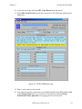
1
High-Accuracy Positioning System User’s Guide Version 2.0 ® High-Accuracy Positioning System User’s Guide Version 2.0 Part # 00190-30000, Rev. A March 2001 ® 150 Rose Orchard Way • San Jose, CA 95134 • USA • Phone (408) 432-0888 • Fax (408) 432-8707 Otto-Hahn-Strasse 23 • 44227 Dortmund • Germany • Phone (49) 231.75.89.40 • Fax(49) 231.75.89.450 adept technology, inc. 41, rue du Saule Trapu • 91300 • Massy • France • Phone (33) 1.69.19.16.16 • Fax (33) 1.69.32.04.62 The information contained herein is the property of Adept Technology, Inc., and shall not be reproduced in whole or in part without prior written approval of Adept Technology, Inc. The information herein is subject to change without notice and should not be construed as a commitment by Adept Technology, Inc. This manual is periodically reviewed and revised. Adept Technology, Inc., assumes no responsibility for any errors or omissions in this document. Critical evaluation of this manual by the user is welcomed. Your comments assist us in preparation of future documentation. A form is provided at the back of the book for submitting your comments. Copyright 2000 by Adept Technology, Inc. All rights reserved. The Adept logo is a registered trademark of Adept Technology, Inc. The SILMA logo is a registered trademark of the SILMA Division of Adept Technology, Inc. AdeptOne-XL, AdeptThree-XL, HyperDrive, Adept 550, Adept 550 CleanRoom, Adept 1850, Adept 1850XP, Adept Cobra 600, Adept Cobra 800, Adept Flexfeeder 250, Adept MV, Adept MV4, AdeptVision, AIM, VisionWare, AdeptMotion, MotionWare, PalletWare, FlexFeedWare, AdeptGEM, AdeptNet, AdeptFTP, AdeptNFS, AdeptTCP/IP, AdeptForce, AdeptModules, AdeptWindows, AdeptWindows PC, AdeptWindows DDE, AdeptWindows Offline Editor, Adept Digital Workcell, and V+ are trademarks of Adept Technology, Inc. Any trademarks from other companies used in this publication are the property of those respective companies. Printed in the United States of America Table of Contents Read Me First . . . . . . . . . . . . . . . . . . . . . . . . . . . . 9 Audience . . . . . . . . . . . . . . . Purpose of This Manual . . . . . . . . Compatibility . . . . . . . . . . . . . What is HPS?. . . . . . . . . . . . . . Overview of HPS . . . . . . . . Theory of Operations . . . . . What Do I Already Need to Know? . What Should I Already Have Done? . Do I Have to Read All the Manuals?. How Can I Get Help? . . . . . . . . . 1 . . . . . . . . . . . . . . . . . . . . . . . . . . . . . . . . . . . . . . . . . . . . . . . . . . . . . . . . . . . . . . . . . . . . . . . . . . . . . . . . . . . . . . . . . . . . . . . . . . . . . . . . . . . . . . . . . . . . . . . . . . . . . . . . . . . . . . . . . . . . . . . . . . . . . . . . . . . . . . . . . . . . . . . . . . . . . . . . . . . . . . . . . . . . . . Installation . . . . . . . . . . . . . . . . . . . . . . . . . . . . Introduction . . . . . . . . . . . . . . . . . . . . . . . Required Equipment . . . . . . . . . . . . . . . . . . Equipment Supplied with the HPS Product . . . User-Supplied Equipment . . . . . . . . . . . . Installing the Software . . . . . . . . . . . . . . . . . Files Included on the Floppy Disk . . . . . . . Copying the HPS Programs . . . . . . . . . . . Storing the Robot Flange Location . . . . . . . . . . Installing and Adjusting the Camera . . . . . . . . . Setting Up the Grid Plate in the Work Envelope Adjusting the Camera Mount Z Height . . . . . Setting Up the AdeptVision System . . . . . . . . . . 2 . . . . . . . . . . . . . . . . . . . . . . . . . . . . . . . . . . . . . . . . . . . . . . . . . . . . . . . . . . . . . . . . . . . . . . . . . . . . . . . . . . . . . . . . . . . . . . . . . . . . . . . . . . . . . . . . . . . . . . . . . . . . . . . . . . 15 . . . . . . . . . . . . Mapping the Work Envelope . . . . . . . . . . . . . . . . . . Introduction . . . . . . . . . . . . . . . . Overview of the Mapping Procedure . . Software Operation . . . . . . . . . . . . The Main Menu . . . . . . . . . . Selecting the Mapping Options . Locating the Grid Plate . . . . . . Beginning the Mapping Process . Storing the Mapping Data to Disk . . . . . . . . . . . . . . . . . . . . . . . . HPS User’s Guide, Rev. A . . . . . . . . . . . . . . . . . . . . . . . . . . . . . . . . . . . . . . . . . . . . . . . . . . . . . . . . . . . . . . . . . . . . . . . . . . . . . . . . . . . . . . . . . . . . . . . . . . . . . . . . . . . . . . . . 10 10 10 10 10 11 12 12 13 14 16 16 16 16 17 17 18 19 20 22 24 25 27 . . . . . . . . 28 28 28 29 31 35 37 38 5 Table of Contents Displaying HPS Map in Graphical Format . . . . . . . . . . . . . . 39 Verifiying the HPS Map . . . . . . . . . . . . . . . . . . . . . . . . 40 Loading Mapping Data from Disk . . . . . . . . . . . . . . . . . . 41 3 Using the Mapped Workspace . . . . . . . . . . . . . . . . . 45 Introduction . . . . . . . . . . . . . . . . . . . . . . . . . . . . . . . . . . 46 Loading the Calibration Data from Disk. . . . . . . . . . . . . . . . . . . 46 Loading the Mapping File with an Application Program . . . . . . 47 4 Loading Multiple Maps in AIM 4.x or Higher . . . . . . . . . . Introduction . . . . . . . . . . . . . . . . . . . . . . . . . . Loading Multiple Maps . . . . . . . . . . . . . . . . . . . . Load AIM and Log In . . . . . . . . . . . . . . . . . Enable HPS . . . . . . . . . . . . . . . . . . . . . . . Copy Records from the HPS Initialization Database Load Multiple Maps . . . . . . . . . . . . . . . . . . 5 . . . . . . . . . . . . . . . . . . . . . . . . . . . . . . . . . . . . . . . . . . 49 . . . . . . The Run-time Subroutines . . . . . . . . . . . . . . . . . . . . 50 50 50 50 52 54 55 The Run-time Subroutines . . . . . . . . . . . . . . . . . . . . . . . . . . 56 A HPS Error Messages . . . . . . . . . . . . . . . . . . . . . . . 59 Alphabetical List . . . . . . . . . . . . . . . . . . . . . . . . . . . . . . . 60 B Installing the Model #600 Ballast . . . . . . . . . . . . . . . . Installation Instructions . . . . . . . . . . . . . Preliminary Steps . . . . . . . . . . . . Matching the Ballast to the Lamp Size . Lamp Operating Voltage Adjustment . C . . . . . . . . . . . . . . . . . . . . . . . . . . . . . . . . . . . . . . . . . . . . . . . . . . . . . . . . Use with Two and Three-Axis Mechanisms. . . . . . . . . . . 67 . . . . 68 68 68 68 71 Overview . . . . . . . . . . . . . . . . . . . . . . . . . . . . . . . . . . . 71 Installation of Camera . . . . . . . . . . . . . . . . . . . . . . . . . . . . 71 Index . . . . . . . . . . . . . . . . . . . . . . . . . . . . . . . 6 HPS User’s Guide, Rev. A 73 Table of Contents List of Figures Figure 1-1 Figure 1-2 Figure 1-3 Figure 1-4 Figure 1-5 Figure 2-1 Figure 4-1 Figure 4-2 Figure 4-3 Figure 4-4 Figure 4-5 Camera, Lens, and Camera Mount Assembly. . Camera Mounted Onto the Robot User Flange . Camera Control Unit . . . . . . . . . . . . . . . . Glass Grid Plate and Ballast . . . . . . . . . . . . Ballast Switches . . . . . . . . . . . . . . . . . . HPS Map . . . . . . . . . . . . . . . . . . . . . . AIM Configuration Menu Page . . . . . . . . . . Edit MotionWare and FlexFeedWare Menu Page Update Configuration Menu Page . . . . . . . . Select Initialization Database Menu Page . . . . HPSINI.DB Menu Page . . . . . . . . . . . . . . . HPS User’s Guide, Rev. A . . . . . . . . . . . . . . . . . . . . . . . . . . . . . . . . . . . . . . . . . . . . . . . . . . . . . . . . . . . . . . . . . . . . . . . . . . . . . . . . . . . . . . . . 20 21 21 23 24 40 50 51 52 52 53 7 Table of Contents List of Tables Table 1 Table 1-1 8 Manuals You Should Have Available. . . . . . . . . . . . . . . 13 Included Files. . . . . . . . . . . . . . . . . . . . . . . . . . . . 17 HPS User’s Guide, Rev. A Read Me First Audience . . . . . . . . . . . . . . . . . . . . 10 Purpose of This Manual . . . . . . . . . . . . . . . . . . . 10 Compatibility . . . . . . . . . . . . . . . . . . . . . . . 10 What is HPS? . . . . . . . . . . . . . . . . . . . . . . . 10 What Do I Already Need to Know? . . . . . . . . . . . . . . 12 What Should I Already Have Done? . . . . . . . . . . . . . . 12 Do I Have to Read All the Manuals? . . . . . . . . . . . . . . 13 How Can I Get Help? . . . . . . . . . . . . . . 14 . . . . . . . . . . HPS User’s Guide, Rev. A 9 Read Me First Audience Audience The High-Accuracy Positioning System User’s Guide is written for someone who is already familiar with V+ software. If you are not familiar with V+ software, please read the V+ Language User’s Guide before using this manual. Additionally, you must already be familiar with the AdeptVision system. See the AdeptVision User’s Guide before using this manual. Purpose of This Manual The purpose of this user’s guide is to introduce you to the High-Accuracy Positioning System (HPS) software, to explain how to install the hardware and software, and to explain how to efficiently use the system. For other manuals related to the use of the High-Accuracy Positioning System, see ”Do I Have to Read All the Manuals?” on page 13. Compatibility This version of HPS is for use with V+ version 12.0 and later. HPS data files created using an earlier version of HPS are not compatible with HPS software version 2.0 and higher. What is HPS? This section provides an overview of the HPS product. It explains the purpose of the product and its theory of operation. Overview of HPS The High-Accuracy Positioning System is designed to improve the planar positional accuracy of an Adept robot in a region selected by you. The selected region can be as large as the size of the mappable area of the grid, or smaller. The system requires that you map the desired region using a special procedure that 10 HPS User’s Guide, Rev. A Read Me First What is HPS? results in the generation of a position compensation data file. It is this map data that characterizes the robot over the selected region and allows the robot to be commanded to move within the region with high accuracy. The HPS software provides a means for loading the map data into V+ program memory. The data must be present in program memory when high-accuracy moves are executed. The HPS system allows you to map an unlimited number of planes. Up to six can be loaded into memory at any given time for immediate access. With this feature, you can achieve high-accuracy positioning over virtually the entire working envelope of the robot. The HPS system also integrates with the Adept arm-mounted vision system. The HPS software and the arm-mounted vision calibration software may be loaded into memory at the same time. The two programs automatically coordinate the camera with the HPS calibration data, resulting in a more highly accurate robot system. The HPS system supports its own camera calibration if the mapped plane is accessed without using vision guidance. Theory of Operations The calibration procedure involves placing a precision grid plate, measuring 20” x 20” (510 mm x 510 mm), into the region to be mapped, and attaching a special end effector to the Adept robot. The end effector is an adjustable camera mount equipped with a micro-sized cube CCD camera and lens. After the precision grid plate is installed, the end effector is placed into the region to be calibrated, and the HPS software is executed. The software scans the grid with the camera and generates compensation data that can then be stored on disk. This calibration data contains compensation data for planar inaccuracies of the robot for the mapped configuration. When this procedure is completed, you can remove the end effector and the grid plate. This procedure needs to be repeated only if the robot is moved or modified, or a different region is selected. NOTE: It is important to note that a two-dimensional plane is mapped. To achieve maximum benefit from the compensation values, compensated motions should occur as close to the mapped plane as possible. For example, in a three-axis system where the XY plane is mapped, the Z height of the tool flange should be the same height as it was during mapping. Otherwise, inaccuracies of the Z axis will render the compensation values useless. Accuracy of the mechanical unit for motions normal to the mapped plane will dictate how far from the mapped plane you can move and still achieve the desired accuracy. HPS User’s Guide, Rev. A 11 Read Me First What Do I Already Need to Know? NOTE: Be sure that the plate is parallel to the plane of the robot end effector What Do I Already Need to Know? This manual assumes that your workcell is built and operating, and that you are familiar with the basic operating and safety procedures for the robot, controller, and system software (V+). In particular, you should know: • How to power up the controller • How to power up and perform start-up calibration of the robot • The safety requirements of your robot and any other devices that operate in the workcell WARNING: When run carelessly or by inexperienced operators, robots and other motion devices can severely injure personnel and cause equipment damage. • The basic operation and use of the optional Manual Control Pendant (MCP) if you have one available • How to install the camera that you will be using with HPS What Should I Already Have Done? Before you proceed, the following tasks must be completed: 12 • Install the robot in the workcell and configure the robot controller. Ensure that the robot can power up, calibrate, and move around in the workspace. • Install the vision system and verify that the camera output appears in the vision window. • Determine the region(s) in the robot work envelope that will require HPS mapping, and clear the workspace to allow room for the HPS grid. Any fixturing, feeder stations, etc., that interfere with the grid must be temporarily removed. HPS User’s Guide, Rev. A Read Me First Do I Have to Read All the Manuals? Do I Have to Read All the Manuals? The HPS User’s Guide (this manual) provides the specific instructions for installing and using the HPS system. However, you should have the following additional manuals available for reference: Table 1. Manuals You Should Have Available Manual Material Covered V+Operating System User’s Guide How to use the V+ operating system. V+ Language User’s Guide Basic concepts and strategies of programming in V+. V+Operating System Reference Guide The monitor commands and their use in the V+ operating system. V+ Language Reference Guide The keywords used in V+, a listing of all error messages, and a supplemental description of the ID Monitor command. AdeptVision User’s Guide Basics of using machine vision software. AdeptVision Reference Guide The keywords used in V+ that relate to vision, prototype recognition algorithms, and perspective distortion. Robot user’s guide Basic capabilities of your robot, as well as how to perform the start-up procedures. Controller user’s guide Basics of using the Adept controller. Instructions for Adept Utility Programs Instructions for running Adept utility programs. Depending on which options you use, you may have to run various Adept utility programs. Keep the manual handy for instructions on any utility program that you may have to run. HPS User’s Guide, Rev. A 13 Read Me First How Can I Get Help? How Can I Get Help? Refer to the How to Get Help Resource Guide (Adept P/N 00961-00700) for details on getting assistance with your Adept software or hardware. You can obtain this document through Adept On Demand. The phone numbers are: (800) 474-8889 (toll free) (503) 207-4023 (toll call) Please request document number 1020. 14 HPS User’s Guide, Rev. A 1 Installation Introduction . . . . . . . . . . . . . . . . . . . . . 16 Required Equipment . . . . . . . . . . . . . . . . . . . . 16 . . . . . . . . . . . . . . . . . . . 17 . . . . . . . . . . . . . . . 19 Installing and Adjusting the Camera . . . . . . . . . . . . . . 20 Setting Up the AdeptVision System . . . . . . . . . . . . . . 25 . . Installing the Software Storing the Robot Flange Location HPS User’s Guide, Rev. A 15 Chapter 1 Introduction Introduction This chapter describes how to install the HPS hardware on an existing robot system. It assumes that the robot and controller have already been installed and are functioning properly. Required Equipment This section describes the equipment required for the HPS installation and setup. Equipment Supplied with the HPS Product The HPS product consists of the following items: • Shipping/storage case • Glass grid plate with integral backlight, ballast (backlight power supply), grounding cable, and AC cord • Camera mount end-effector • Camera, camera control unit (CCU) and lens • One floppy disk that contains the HPS software • HPS license • This manual User-Supplied Equipment In addition to the items contained in the HPS product, the following items are needed: 16 • An Adept robot and controller • A V+ system disk (version 12.0 or later) • A sturdy table or mounting surface to hold the grid plate • A Manual Control Pendant (MCP) for positioning the robot during HPS calibration • An Adept Enhanced Vision (EVI) board, a Vision (VIS) board, or an Adept Advanced Vision Interface (AVI) board • A two- or four-camera breakout cable, interfacing to the EVI, VIS, or AVI HPS User’s Guide, Rev. A Chapter 1 Installing the Software NOTE: A four-camera breakout cable requires an external 12 V. power supply for the camera. • A 10 m camera power cable, interfacing to the camera (through the CCU) • SIO, AWC floppy drive, or networked PC with a floppy drive, running an NFS server • M5 and M2.5 hex wrenches Installing the Software This section describes how to install the software for the HPS product. Files Included on the Floppy Disk Table 1-1 describes the files that are included on the floppy disk supplied with the HPS product. Table 1-1. Included Files File Type File Name Description HPS_MAP.V2 High-accuracy mapping software B HPS_RUN.V2 Run-time software routines used to apply correction B EXERCISE.V2 Sample mechanism exercise routine R AREA1.DAT Camera calibration data for micro-cube camera A Notes: In the File Type column: B = Binary, A = ASCII, and R = Read only. HPS User’s Guide, Rev. A 17 Chapter 1 Installing the Software Copying the HPS Programs You can load the programs directly from the HPS floppy disk. However, Adept recommends that you use the following procedure to copy some or all of the programs to a subdirectory on the Adept controller’s hard drive (drive C) or Compact Flash (drive D). NOTE: If you have the AdeptNFS option, and your Adept controller is on a network with another computer that has a diskette drive, you can use the DISKCOPY utility to copy the program files from nfs>unit: to the controller. To do this, you must have an NFS mount defined on the V+ system that can access the desired files on the remote computer. In the procedure below, specify nfs> and the appropriate NFS mount in place of the references to the A drive. (See the Instructions for Adept Utility Programs manual for more details about the DISKCOPY utility, and the AdeptNet User’s Guide for more details about AdeptNFS.) NOTE: If you are using V+ version 12, specify drive C in place of drive D in the following procedure. If your Adept controller includes an AWC floppy drive (FDD), specify drive B in place of drive A. 1. If it does not already exist, create a subdirectory to receive the files (refer to the V+Operating System User’s Guide if you need more information about the FDIRECTORY command). Type: fdirectory/c d:\hps\ 2. Type load d:\util\diskcopy to load the DISKCOPY utility. 3. Type ex 1 a.diskcopy to execute the DISKCOPY utility. 4. Use the DISKCOPY utility to copy all the files from drive A to drive D: a. Insert the HPS Disk into the floppy drive (drive A). b. Choose: 4=> Copy multiple files. 18 c. When prompted, type a to specify drive A as input, and type d to specify drive D as output. d. Type y to verify the copy operations. e. Type *.* to specify which files to copy. f. Type \hps\ as the output subdirectory. g. Type y to replace any existing files of the same name. HPS User’s Guide, Rev. A Chapter 1 Storing the Robot Flange Location h. When the name of the first file is displayed, type g (Go) to copy all files. Storing the Robot Flange Location During the calibration process, it is essential that the flange of the robot be asclose as possible to the position in which it will operate when your application is running. To determine this value: 1. Type tool null at the terminal to ensure that the TOOL transformation is set to NULL. 2. Make sure that the end effector for your specific application is attached to the robot. 3. Place the robot in FREE mode using the Manual Control Pendant. 4. Move the robot so that the tip of the end effector is touching the work surface of the application. (The work surface of the application is the plane in which high-accuracy motions are to be performed.) 5. Place the tip of the tool at the working surface. 6. Type here mapz to record the location of the robot. 7. Type storel mapz to save the value of this location onto disk. HPS User’s Guide, Rev. A 19 Chapter 1 Installing and Adjusting the Camera Installing and Adjusting the Camera CAUTION: Make sure that the robot is safely powered down and the controller power is off before installing the camera mount or connecting camera cables. Do not attempt to hot-plug the camera cable with controller power on, or the camera could be damaged. 1. Prior to the actual installation, remove the camera mount from the packaging case and examine it. This assembly consists of an aluminum flange mount and slider assembly on which the camera and lens are mounted. On the flange mount is a raised circular ring for precise alignment to the central axis of the standard Adept user flange. For rotational alignment, a steel pin on the outer edge of the flange mount fits into a mating dowel-pin hole on the flange. The camera is essentially a 20 mm cube with a cable on the side and a 20 mm long cylindrical lens. The camera is mounted to the camera mount slider by the lens. (See Figure 1-1.) Lens Camera Mount Assembly Camera Figure 1-1. Camera, Lens, and Camera Mount Assembly 20 2. Remove any end effector that is attached to the robot. 3. Mount the camera mount onto the robot user flange, aligning the pin with the mating hole on the flange, and secure with three M6 screws. (See Figure 1-2 on page 21.) HPS User’s Guide, Rev. A Chapter 1 Installing and Adjusting the Camera Robot user flange Camera Figure 1-2. Camera Mounted Onto the Robot User Flange 4. Check the settings on the camera control unit (CCU). Make sure that the switch labeled “MODE” is set to 1/60, and the switch labeled “A F M” is set to "A". See Figure 1-3. Figure 1-3. Camera Control Unit 5. Plug the cable wired directly to the camera into the "CAMERA" receptor on the CCU. HPS User’s Guide, Rev. A 21 Chapter 1 Installing and Adjusting the Camera 6. Plug the Camera #1 camera cable from the Adept EVI, VIS, or AVI vision board into the receptor on the CCU marked “DC IN/SYNC”. 7. Route the camera cables out of the work envelope of the robot. It is recommended that the cables be attached with plastic tie-wraps to the cable track or fly-over harness of the robot to secure them during robot motion. Mount the CCU unit securely in place on the robot if it cannot be placed outside of the work envelope. NOTE: Be sure to leave enough slack in the cable for theta axis rotation and robot motion during calibration. Connect all cables before powering up the controller. 8. When the robot controller is powered up, make sure that the image from the camera is visible in the Vision window. If not, verify that all of the cables are connected correctly, and all necessary licenses are installed in the system per the AdeptVision User’s Guide. Setting Up the Grid Plate in the Work Envelope The grid plate must be placed in the area to be mapped by the robot. It is critical that the plate rests on a sturdy support. For the mapping process to function correctly, the tilt of the plate must be minimized relative to the TOOL coordinate system. Three thumbscrews are provided on the grid plate to assist in leveling the plate. The entire region that is to be mapped must lie within the boundaries of the glass grid. To verify this: 1. Place the robot in FREE mode using the Manual Control Pendant. 2. Move the robot so that the end effector traces the desired mapped area. NOTE: It is not necessary for the entire grid to lie within the work envelope, since the HPS software will map the portion of the grid that can be reached by the robot. NOTE: Regions larger than the physical grid may be mapped by repositioning the grid and creating a second map. It is possible to have the HPS software map a region that is significantly smaller than the full grid size. Installed behind the glass grid plate is a thin backlight for illumination of the camera field of view. This backlight is powered by a ballast which has been included in the HPS case. To connect the ballast: 22 HPS User’s Guide, Rev. A Chapter 1 Installing and Adjusting the Camera 1. Plug the white cable extending out of the grid into the mating receptor on the ballast. Ballast Glass grid plate Figure 1-4. Glass Grid Plate and Ballast 2. Locate the green/yellow ground wire attached to the frame of the grid plate. Connect the ring lug from the ground wire to an earth ground connection in the work cell. CAUTION: Due to the capacitive coupling between the backlight and metal frame, it is necessary to bring the potential of the frame to earth ground to avoid a shock. 3. Plug the AC power cord of the ballast into a 110 V, 60 Hz supply, and turn the ballast power switch to “ON”. Make sure that the switch marked “FLASHING” is set to “OFF”. The backlight should now illuminate with a steady blue-white light. HPS User’s Guide, Rev. A 23 Chapter 1 Installing and Adjusting the Camera Flashing control switch Ballast power switch Figure 1-5. Ballast Switches Adjusting the Camera Mount Z Height Now that the plate is installed in the work envelope, the Z length of the camera mount must be adjusted. The objective of the following procedure is to ensure that the position of the Z axis of the robot is the same during the calibration process as it will be when the application program is running. This is done by placing the robot at the location saved using the procedure described in ”Storing the Robot Flange Location” on page 19 and adjusting the end effector until the tip of the camera lens is approximately 19 mm above the grid plate. To adjust the Z length of the camera mount: 1. Type speed 5 at the system keyboard to reduce the monitor speed. CAUTION: We recommend that you reduce the monitor speed for safety, and for the protection of the end effector and the plate. 24 2. Type load mapz.lc to restore the location that was recorded earlier when the end effector was on the robot. This is the location “mapz” which was saved using the procedure described in ”Storing the Robot Flange Location” on page 19. 3. Loosen the two M3 screws holding the sliding portion of the end effector in place, and slide the end effector up until it is near the highest position. Re-tighten the screws to lock the slider in place. HPS User’s Guide, Rev. A Chapter 1 4. Setting Up the AdeptVision System Type tool null to make sure that the V+ tool transformation is set to NULL. CAUTION: Make sure that your finger is on the Manual Control Pendant’s PANIC button before you execute the next command. Be prepared to press the PANIC button if it appears that the end effector will touch the plate during the motion. 5. Type do move mapz to instruct the robot to move back to the position that was saved. The robot will move slowly. 6. When the robot has stopped, adjust the Z height of the camera mount until the tip of the camera lens is 19 mm above the grid plate. The height of the camera is adjusted by pushing or pulling on the slider. If the tip of the camera lens is more than 19 mm from the surface of the plate when the camera mount slider is at its lowest position, it will be necessary to raise the plate. 7. Ensure that the camera is in good focus within the entire region to be mapped. Do this by enabling MANUAL mode with the MCP and slowly moving the robot in world mode above the grid in the X and Y directions. If the camera is consistently out of focus over the entire region, adjust the slider until the image is sharp. If the camera moves in and out of focus, the grid plate is not level to the robot. Use the thumbscrews on the grid frame as necessary to level the grid and ensure sharp focus over the region to be mapped. Setting Up the AdeptVision System The installation and setup of the AdeptVision system is beyond the scope of this manual. Please refer to the AdeptVision User’s Guide and AdeptVision Reference Guide for details. HPS User’s Guide, Rev. A 25 2 Mapping the Work Envelope Introduction . . . . . . . . . . Overview of the Mapping Procedure Software Operation . . . . . . . . . . . . . . . . . . . . 28 . . . . . . . . . . . . . 28 . . . . . . . . . . . . . 28 HPS User’s Guide, Rev. A 27 Chapter 2 Introduction Introduction This chapter describes the steps that must be followed to map the workspace. Overview of the Mapping Procedure The mapping procedure is controlled by the HPS mapping software. After a brief setup procedure that is guided by the software, the mapping software generates the calibration data. The time required for this process varies depending on the size of the region to be mapped, and the mapping options. A mapping of the full 696 mm by 576 mm mappable area in increments of 12 mm (0.4728") between single measurements requires about one-half hour. NOTE: If an ESTOP occurs which halts the mapping procedure, do not stop the task and execute the task again or all data will be lost. Instead, clear the ESTOP, make sure that the manual control pendant is in COMP mode, and type PROCEED to restart the mapping. Software Operation To load and execute the HPS mapping software:. NOTE: Use drive C in place of drive D if you are using V+ version 12. 28 1. Type load d:\hps\hps_map to load the mapping software. 2. Press the COMP/PWR button on the Manual Control Pendant to enable power. 3. Type ex 1 a.hps_map to start the HPS mapping software. HPS User’s Guide, Rev. A Chapter 2 Software Operation The Main Menu When you start the HPS software, the HPS main menu is displayed on the terminal: HIGH-ACCURACY POSITIONING SYSTEM, MAPPING ROUTINES (Version 2.0) Copyright (c) 1986-2000 by Adept Technology, Inc. MAIN MENU 0 1 2 3 4 5 6 7 8 => => => => => => => => => Exit Select Mapping Options Locate Plate Begin Mapping Store Mapping to Disk Load Mapping from Disk Display Error Report Display HPS Map Test HPS Map Enter selection: The main menu allows you to activate various portions of the HPS software. To activate one of the choices, enter the number shown next to that choice and press the ENTER key. Each of the choices will be discussed both briefly (below) and in more detail as they are needed in the explanations that follow. Exit This menu choice causes the HPS software to stop, and returns to the V+ monitor. You can type ex 1 a.hps_map to resume the HPS software. Select Mapping Options The HPS program allows you to customize many of the parameters that govern the mapping process. These options include, but are not limited to, selecting the map region, setting the speed and acceleration of the robot, and select the sampling frequency for computing compensation values. Locate Plate This menu choice determines the calibration of the camera and the location of the plate. This operation must be performed before the plate is mapped. If an attempt is made to map the plate before locating the plate, the software displays an error. HPS User’s Guide, Rev. A 29 Chapter 2 Software Operation Begin Mapping This menu choice starts the mapping process. At the completion of the mapping, an error report is generated that summarizes the results. Store Mapping to Disk This menu choice saves the calibration data (generated by the Begin Mapping menu choice) to a disk file. CAUTION: This step must be performed after the mapping is complete or the mapping data will be lost. Load Mapping from Disk This menu choice loads the contents of a mapping data file into memory. In order for the menu choice to work, the file HPS_RUN.V2 on the HPS software diskette must have been loaded into memory. The mapping software attempts to load this file automatically for you, but if it has not been loaded and Load Mapping from Disk is selected, the software displays an error. If an error message is displayed, consult ”HPS Error Messages” on page 59 for a list of all errors and their causes. Display Error Report This menu choice will work only after a mapping operation has been performed. It displays detailed information about the mapping results and any mapping errors that may have occurred. Display HPS Map Once a mapping has been completed, or an HPS calibration data file has been loaded into memory, a graphical display of the offsets can be plotted on the screen. The X and Y offsets can be displayed in a color contour plot format for visual confirmation of the mapping results. If an attempt is made to display the HPS map without the appropriate data in memory, the software displays an error. Test HPS Map Once a mapping has been completed, or an HPS calibration data file has been loaded into memory, the map can be tested for accuracy. The run-time HPS routines contained in the file HPS_RUN.V2 are used to determine the correction for a user-defined location on the grid. If an attempt is made to test the HPS map without the appropriate data in memory, the software displays an error. As the software runs, it may detect an unusual situation. If this happens, the software displays an error message. If an error message is displayed, consult ”HPS Error Messages” on page 59 for a list of all errors and their causes. 30 HPS User’s Guide, Rev. A Chapter 2 Software Operation Selecting the Mapping Options When the Select Mapping Options menu choice is activated, a second menu is displayed, listing the options for the mapping procedure: HIGH-ACCURACY POSITIONING SYSTEM, MAPPING ROUTINES (Version 2.0) HPS MAPPING OPTIONS 0 1 2 3 4 5 6 7 8 9 10 11 12 13 14 15 16 17 => => => => => => => => => => => => => => => => => => Exit Verbose Comments Display Vision Tools Plot Data During Map Log Raw Offset Data Optimize Graphics for VGB Limit Map Region Mapping Density (gridlines) Camera Auto-Focus Backlash Compensation Thermal Compensation Quit on Excess Errors Modify Motion Parameters Camera Number Camera Calibration File Robot Number Modify Grid Parameters Restore Default Options ENABLED ENABLED ENABLED ENABLED DISABLED ENABLED every 3 DISABLED DISABLED DISABLED DISABLED grid lines 1 area1.dat 1 Enter selection: Exit Select this menu choice to return to the main menu. Verbose Comments When this menu choice is selected, the HPS mapping software displays more detailed information during the camera calibration and while locating the grid plate. By default, this option is disabled (only brief comments are displayed during the calibration and grid plate location process). HPS User’s Guide, Rev. A 31 Chapter 2 Software Operation Display Vision Tools This menu choice can be enabled to display the line finders, rulers, inspection windows, etc., if needed for evaluation. To ensure the fastest performance, the vision tools used to make measurements of the robot position offsets with respect to the grid are not displayed in the Vision window (by default). Selecting this menu choice may increase mapping time noticeably due to the extra processing cycles required to draw the tools in the Vision window. ( This is noticed especially on systems using AdeptWindows.) Plot Data During Map At the end of each row scan during the mapping process, the robot X and Y position offsets can be plotted as functions of distance along the grid. This plot can be useful in determining the effect of averaging several measurements for each location, the amount of backlash and noise in the system, and the optimal measurement density for the map. By default, this plot is not displayed. Log Raw Offset Data If this menu choice is selected, the raw X and Y position measurements are logged to a user-defined text file during the mapping. This file contains the following data: • Location Number • X Position on Grid (mm) • Y Position on Grid (mm) • X Offset (mm) • Y Offset (mm) Optimize Graphics for VGB The vision graphics for the HPS mapping software have been optimized for best performance with an AWC controller and the AdeptWindows PC user interface. The amount of data displayed in the Vision window has been minimized to reduce delays induced when running the system over a network. However, if a VGB board is used for the display, enabling this option optimizes the vision resolution and video modes to take advantage of the high-speed VGB vision bus connection. Limit Map Region The HPS map region can be sized and aligned easily to either the world coordinate system or the grid coordinates. This option can be especially useful to define a small area for quickly testing the HPS system or reducing mapping time significantly. If you choose option 1, "Rectangular region in grid coordinates", you will be prompted to move the mechanism around the grid to define the 32 HPS User’s Guide, Rev. A Chapter 2 Software Operation borders of the desired region aligned with the rows and columns of the grid. If you choose option 2, "Rectangular region in world coordinates", you will be prompted for the minimum and maximum X and Y world coordinates of the desired region. By default, this option is disabled, and only the borders of the grid or the work envelope limit the mapped area. Note that if this menu choice is selected, the robot must be left inside the boundaries of this region before the grid plate is located. NOTE: If this option is changed after the grid plate has already been located, the mapping procedure must be repeated to reflect the modified map boundary. Mapping Density (gridlines) The frequency of measurements during the mapping process is user-selectable. The default is every one grid line, which corresponds to one measurement every 2 mm. For a faster map time, this value can be increased up to 12 (corresponding to one measurement every 24 mm). Camera Auto-Focus If the camera auto-focus is enabled, and a Z axis is configured on the system, the HPS software will move the Z axis slightly during calibration of the camera. This motion will be used to determine the optimal focus of the camera for best vision recognition of the grid. NOTE: Be sure to verify that the edges of the grid are crisp. Backlash Compensation The HPS mapping software can be configured to take several measurements with the camera at the same grid location approached from different directions in order to average out backlash and noise in the data. Enabling backlash compensation allows you to select the number of measurements to be taken at each location (from 1 to 20). NOTE: Enabling backlash compensation can increase mapping time significantly. Thermal Compensation Because the metal structure of the robot changes length with temperature, the accuracy of the tool tip can be affected. The growth of a steel ballscrew is approximately 1.2 x 10⁻⁵ mm/mm/deg C, and that of an aluminum link is roughly twice as large at 2.2x10⁻⁵ mm/mm/deg C. Therefore, a robot that was accurately mapped at ambient temperature may grow in length due to motor and HPS User’s Guide, Rev. A 33 Chapter 2 Software Operation friction heating when running the application and subsequently lose accuracy. Enabling the thermal compensation option allows you to specify a custom exercise routine to warm up the robot before mapping, and optionally re-heat the robot at intervals during the map to keep it warm. This custom routine must follow the guidelines listed below: • The routine must contain a parameter list of the form: (ex.time, err). The parameter ex.time is an input to the routine, specifying the length of time to exercise the robot in minutes. The parameter err is an output of the routine, and should be TRUE if there is an error condition. • The routine must allow the robot to safely depart from the grid surface before exercising, and avoid any motion that may damage the camera and/or camera cable. NOTE: A sample exercise routine named EXERCISE.V2 is provided as a read-only file on the HPS Disk. You may use this routine as a basis for a custom exercise routine that fits the desired application. Quit on Excess Errors This menu choice allows you to specify the maximum number of errors detected during the mapping process before the software declares a fatal error and stops. The default value is -1, which disables this option. With the default setting, the mapping will not be halted after any number of recoverable errors. Modify Motion Parameters This menu option allows you to adjust the speed, acceleration, deceleration, settling tolerance, and delay time for all robot motions in order to optimize mapping time or accuracy. Camera Number This menu choice allows you to select the camera to be used for vision operations during the mapping procedure. NOTE: If this option is changed after the grid plate has already been located, the mapping procedure must be repeated. By default, the camera number is 1. 34 HPS User’s Guide, Rev. A Chapter 2 Software Operation Camera Calibration File Included with the HPS software is a default camera calibration file (named AREA1.DAT) for the micro-size cube camera and lens combination. If a custom camera and lens are used with the HPS software, another calibration file can be specified. This file can be created using the ADV_CAL utility that is included on the Adept V+ Utility Disk. See the manual Instructions for Adept Utility Programs for details. NOTE: If this option is changed after the grid plate has already been located, the mapping procedure must be repeated. Robot Number This menu choice allows you to select the robot to map. NOTE: If this option is changed after the grid plate has already been located, the mapping procedure must be repeated. By default, the robot number is 1. Modify Grid Parameters This menu choice allows you to modify the default grid parameters. Both the grid pitch (distance between gridlines), and gridline width can be modified. NOTE: The parameters should not be changed if the Adept-supplied grid plate is used. NOTE: If this option is changed after the grid plate has already been located, the mapping procedure must be repeated. Restore Default Options The default value for every mapping option is restored if this menu choice is selected. Locating the Grid Plate This operation determines the calibration of the camera and the location of the plate. It must be performed before the plate is mapped. If an attempt is made to map the plate before locating the plate, the software displays an error. If an error is displayed, consult ”HPS Error Messages” on page 59 for a list of all errors and their causes. The system will display information that instructs you to position a grid intersection in the center of the Vision window, within the radius of the green circle displayed there. It is not critical which grid intersection you position the camera over, as long as it is within the region selected to be mapped. HPS User’s Guide, Rev. A 35 Chapter 2 Software Operation • If your system is equipped with a Manual Control Pendant, you can enable MANUAL mode with the MCP and move the robot in world mode until the intersection is centered. If there is no MCP attached to the system, power will be disabled and you can move the robot by hand to center the intersection. • The intersection should appear clearly in the center of the vision window, with sharp black gridline edges, and with well-defined contrast to the white background. If this is not the case, check the backlight, the focus of the camera, or the rest of the vision system as necessary. • Press the ENTER key when you are ready to continue. The software will attempt to locate a grid intersection in the vision window. If it is successful, the message, “Located grid intersection.”, is displayed. Additionally, a small cross is drawn in the vision window at the point where the intersection was located by the vision system. If a grid intersection could not be located, you are notified by the message, “* Unable to locate a grid intersection*”. Respond to the prompt by typing Y to try again; or type N to return to the main menu. If the robot is equipped with a theta axis, you are prompted with the following: About to rotate theta axis by # degrees. Verify that the camera cable has enough slack to allow rotation. Proceed (Y/N)? Respond to this prompt with Y when the camera cable has been checked to verify that it has enough slack to allow the theta axis to rotate. At this point, the HPS software executes an automatic calibration procedure that takes a few minutes to complete. The robot undergoes a series of motions in the map region to accomplish the following: • Calibrate the vision reference frame to the world reference frame. • Calibrate the camera scale factor, using gridlines as the reference. • Quickly estimate the grid orientation with respect to the world coordinate system by tracing a gridline for approximately 20 mm. • Trace the border of the region to be mapped. This area is limited by the intersection of the robot work envelope, the grid borders, and the map region limits selected with the Mapping Options menu. • Move the robot to the origin of the grid region to be mapped. When the process completes successfully, the system displays the following data and prompts you to press ENTER. *SUMMARY* Camera X axis rotated from world X axis by: 36 HPS User’s Guide, Rev. A #deg Chapter 2 Software Operation Grid X Grid X Number Number Number axis rotated from camera X axis by: axis rotated from world X axis by: of mappable row gridlines (Grid Y axis): of mappable column gridlines (Grid X axis): of mappable gridline intersections: #deg #deg # # # Beginning the Mapping Process NOTE: It is very important that the plate be clean before the mapping is started. Even very small particles of dust or dirt will be seen by the camera and may result in incorrect measurements. The plate can be cleaned with a lint-free cloth and some glass cleaner. If a liquid cleaner is used, use it sparingly. WARNING: Be sure to unplug the ballast before cleaning the plate. As you clean the plate, be careful not to damage the backlight with excess liquid. Although the edges of the plate have a liquid seal, use of excessive liquid can cause some to seep under the glass plate and cause damage to the backing material. 1. Locate the plate using the procedure described in the preceding section. 2. Select Begin Mapping from the main menu. The following prompt is displayed: READY TO MAP PLATE Are you sure (Y/N) ? If you respond to this prompt with Y, the robot will begin to scan the plate. As the scanning occurs, the software displays information about the rows and columns being scanned. If Plot Data During Map was chosen from the Mapping Options menu, a plot of the X and Y position offsets is displayed after each column has been mapped. 3. When the mapping process is complete, the program turns off arm power and a summary of the mapping operation is displayed using the following format: *** Mapping Summary *** Start time: End time: Number of points scanned: Number of Errors: Grid X Axis Offsets mean: minimum: maximum: standard deviation: # # #mm #mm #mm #mm HPS User’s Guide, Rev. A 37 Chapter 2 Software Operation Grid Y Axis Offsets mean: minimum: maximum: standard deviation: #mm #mm #mm #mm The number of points scanned varies with the mapped area size and measurement density. The “Number of Errors” field should normally be zero, and should be noted carefully. The occurrence of errors indicates that the plate was dirty or damaged, and that the mapping package was unable to locate an intersection or measure the position offset after taking a picture. In this case, the data is interpolated from neighboring data points. However, if the number of errors is large (greater than three for example), the plate should be inspected for signs of dirt or damage and cleaned. Once the inspection is complete, the mapping should be performed again. NOTE: A mapping of the entire plate at a resolution of 1 can take approximately 10 hours. A mapping of the the entire plate at a resolution level of 3 takes approximately 1 hour while a mapping at a level of 6 takes approximately 15 to 20 minutes Storing the Mapping Data to Disk The HPS system does not save the calibration data to disk automatically. To save the information: 1. Select Store Mapping to Disk from the main menu. The following information is displayed: READY TO STORE HPS DATA TO DISK FILE. DATA FROM MAP 1 WILL BE STORED. Enter name of HPS data file. (Press RETURN to abort) Filename: 2. Default file extension is ‘.hps’. At the Filename prompt, respond with a file name of the form ffffffff.ext, where “ffffffff” is the filename and “.ext” is the optional file extension. For example: mymap.hps. (If you press ENTER without entering a filename, the store operation is cancelled.) The filename you specify is validated by the system. If it is valid, the following prompt is displayed: File information line: 38 HPS User’s Guide, Rev. A Chapter 2 Software Operation 3. At the prompt, enter a description of the map and press the ENTER key. (The description is an informational line that is stored with the data. Whenever the map is loaded in the future, the description line is displayed, allowing you to decide whether or not this is the correct map.) The system writes the data to the file. 4. At the prompt, press the ENTER key to return to the main menu. Displaying HPS Map in Graphical Format Once a map is in memory, either from a recent mapping process, or one loaded from disk, the resulting error map can be viewed in a color graphical format. The plot resembles the format of a topographical map. With the proper settings selected, the system displays the HPS map using contour lines representing increasing levels of accuracy in order to give you a better understanding of the mechanism accuracy. To view the HPS map, select Display HPS Map from the main menu. You are asked to enter several parameters concerning plot density and the distance between contour lines. 0 1 2 3 4 5 => => => => => => Exit Map Number Density for Plotting HPS Map Interval Size for Contour Line Offset to Display for Plot Display Plot 1 1 mm 0.05 mm Total Radius Exit Select this menu choice to return to the main menu. Map Number This menu choice allows you to choose the map that you want to display. Density for Plotting HPS Map This menu choice allows you to change the density at which data points are plotted. For a map covering a large physical area, use a larger plot density. For a smaller map, use a smaller plot density. If the density selected is very small, it may take several minutes to display the entire plot. Interval Size for Contour Line This menu choice allows you to change the accuracy error between contour lines. For example, if this value is set at 0.02 mm, each contour line will represent a change in error of 0.02 mm. The contour lines change in color from gray to yellow to indicate increasing error. HPS User’s Guide, Rev. A 39 Chapter 2 Software Operation Offset to Display for Plot This menu choice allows you to change the type of error displayed on the plot. Y-axis error, X-axis error, and total error radius can be selected. Display Plot This menu choice generates the map. The map generation may take several minutes to complete, depending upon plot density, map size, and processor speed. As an example, the following map indicates that as the robot moves further from the origin, the error increases. The color of the plot lines indicate the size of the error. Colors listed in order of increasing size are as follows: blue, light blue, light gray, light green, green, and yellow. Figure 2-1. HPS Map Verifiying the HPS Map With a mapping completed (or loaded from disk), it is possible to verify the effectiveness of the map in addition to viewing the map graphically. This is most effective immediately after a map has been created and the grid is still in place, with the camera on the flange mount. The verification moves the robot around the grid to user-defined locations, and demonstrates the increase in accuracy made possible by the map. For HPS map verification, select Test HPS Map from 40 HPS User’s Guide, Rev. A Chapter 2 Software Operation the main menu. At the prompt, enter the HPS map number to test. If the map is not in memory, the program displays an error message. If an error is displayed, consult ”HPS Error Messages” on page 59 for a list of all errors and their causes. If the map is available, the following is displayed: Minimum Minimum Maximum Maximum X Y X Y axis axis axis axis position position position position available available available available on on on on grid: grid: grid: grid: #mm #mm #mm #mm The blue crosshair indicates the center of the vision window Continue with HPS map testing (Y/N)? CAUTION: The next steps will cause the robot to move to the locations used in the mapping process at the Z-axis height defined for the mapping. Be sure that the workspace is free from obstruction, and that the robot can move safely over this area. Answer Y to the prompt, and enter the grid coordinates that you desire to test. Enter grid X-Axis location (mm): Enter grid Y-Axis location (mm): Using no correction, the robot moves to the commanded grid position, and after a few seconds, moves to the corrected position. The results of the inverse HPS correction function are displayed, verifying the inverse calculation. Loading Mapping Data from Disk A set of mapping data that has been saved on disk may be loaded using the Load Mapping from Disk menu choice. NOTE: It is also possible to load a mapping file without using the HPS menu. For details, see the section entitled, ”Loading the Calibration Data from Disk” on page 46. In order for this menu choice to work, the file HPS_RUN.V2 must have been previously loaded by the mapping software. If this could not be done, and you select the Load Mapping from Disk menu option, the program reminds you to load the HPS_RUN.V2 file. To load the mapping data from disk once the contents of HPS_RUN.V2 are in memory: HPS User’s Guide, Rev. A 41 Chapter 2 1. Software Operation Select Load Mapping from Disk from the menu. The following information is displayed: READY TO LOAD HPS FILE FROM DISK Enter the name of the HPS data file. ’.hps’. (Press RETURN) to abort) Filename: Default file extension is 2. Type the filename under which the data is stored. As before, you may omit the extension and it will default to “.HPS”. After you specify the filename, the system will check its validity. If the filename is valid, it will read the file and display the contents. The file header contains information that was saved when the data was originally generated. It includes the size of the map, the location of the starting corner of the map, the serial number and configuration of the robot, the user information line, and the date and time that the mapping was performed. Additionally, there is information displayed concerning the number of rows and columns in the map, the grid map and measurement spacing, and the order of polynomial fit. 3. The following prompt is displayed below the file header information: Map number to hold data: The HPS system is capable of loading calibration data from several maps into memory at the same time. (The potential number of maps is limited only by the available memory in the controller.) In order to identify the maps, it associates a “map number” with each set of data. The assignment of the map number to a set of mapping data is done when the data is loaded into memory. You must select a “map number” (a small positive integer, preferably from 1 to 10) when the loading is done. 4. Select a map number for this set of mapping data, enter it in response to the prompt, and press the ENTER key. (If you have only one map to load into memory it is suggested that you load it into map number 1.) NOTE: If you load a map with a map number and later load another map with that same number, the mapping information contained in the first load will be overwritten by the second load. 5. The following prompt is displayed which will request confirmation before actually loading the data: Data will be stored in map 1. Do you wish to abort reading the file? (Y/N) 6. 42 Type N and press the ENTER key to read the data into memory. The system will load the file information from disk. HPS User’s Guide, Rev. A Chapter 2 Software Operation NOTE: Be sure to record the map numbers that you associate with each set of mapping data. They will be needed when your application program attempts to access the calibration data. HPS User’s Guide, Rev. A 43 3 Using the Mapped Workspace Introduction . . . . . . . . . . Loading the Calibration Data from Disk . . . . . . . . . . . . . 46 . . . . . . . . . . . . 46 HPS User’s Guide, Rev. A 45 Chapter 3 Introduction Introduction This section describes the HPS run-time software, which is provided in the file, HPS_RUN.V2. It explains how to load calibration data file that was previously generated. The routines that must be incorporated into the user programs in order to access the calibration data are described in the next chapter. To use the calibration data file from the previously mapped workspace: 1. Load the run-time software into memory. a. Type cd d:\hps to change to the HPS directory. b. Load the HPS run-time software by typing load hps_run.v2. NOTE: If you are using V+ version 12, specify drive C in place of drive D. If your Adept controller includes an AWC floppy drive (FDD), specify drive B in place of drive A. 2. Load the calibration data from disk. See the next section. 3. Incorporate the HPS CALL statement(s) into the user program to access calibration data. See Chapter 5. 4. Execute the user program with HPS corrected positioning. Loading the Calibration Data from Disk Before the run-time routines can be used, the calibration data must be loaded into memory. There are three ways of accomplishing this: 46 1. With both HPS program files loaded (HPS_MAP.V2 and HPS_RUN.V2), start the mapping program by typing ex 1 a.hps_map. Select Load Mapping from Disk from the main menu and respond to the prompts as described in the earlier section. (See “Loading Mapping Data from Disk” on page 41.) 2. With only the file HPS_RUN.V2 loaded, execute the HPS load subroutine by typing ex 1 hps.load. Specify the disk file to load by responding to the prompts. The prompts are identical to the ones you see if you initiate the load operation from the main menu. 3. The third method uses a V+ routine called hps.read.data and is described in the next section. HPS User’s Guide, Rev. A Chapter 3 Loading the Calibration Data from Disk The first method requires the HPS_MAP file to be loaded into memory. Since this file is large and occupies a lot of program memory, it is often recommended to load the data using the second method mentioned above. This alternative method requires only that the much smaller file, HPS_RUN.V2, be loaded into memory. Loading the Mapping File with an Application Program It is possible to have your application program load a mapping file using the V+ routine, hps.read.data( ). The calling sequence is shown below: CALL hps.read.data(mode, $fname, sel, parms[], $parms[], err) The first three arguments to the routine are inputs and are defined as follows: mode is the mode of the routine (either 0 = "info" or -1 = "load") is the data file spec is the map number to be assigned in the data $fname sel The last three arguments to the routine are outputs and are defined as follows: parms[] are the real-valued data parameters: parms[1] model number parms[2] parms[3] serial number configuration (0=RIGHTY, 1=LEFTY) parms[4] number of rows parms[5] number of columns parms[6] grid spacing in mm parms[7] X component of grid frame parms[8] Y component of grid frame parms[9] Z component of grid frame parms[10] yaw component of grid frame parms[11] pitch component of grid frame parms[12] roll component of grid frame $parms[] err are the string-valued data parameters: $parms[1] file header record $parms[2] user information line $parms[3] mapping start time If "err" is >= 0, there is no error If "err" is between 0 and -9999, an I/O error has occurred If "err" is = -10,000, the HPS data file is not valid HPS User’s Guide, Rev. A 47 4 Loading Multiple Maps in AIM 4.x or Higher Introduction . . . . . . . . . . . . . . . . . . . . 50 Loading Multiple Maps . . . . . . . . . . . . . . . . . . . 50 . . . HPS User’s Guide, Rev. A 49 Chapter 4 Introduction Introduction This section describes how to load multiple maps when using AIM version 4.x or higher. Loading Multiple Maps Load AIM and Log In 1. Load AIM. 2. Log in with system customizer access. Enable HPS 3. Select Utilities, System Configuration from the menu. The following menu page is displayed. Figure 4-1. AIM Configuration Menu Page 4. 50 Select Edit Current Configuration. The following menu page is displayed. HPS User’s Guide, Rev. A Chapter 4 Loading Multiple Maps Figure 4-2. Edit MotionWare and FlexFeedWare Menu Page 5. Select the HPS Module by double-clicking on the module in the Plug-ins NOT currently selected: window. 6. Click Update to end the configuration process. The following menu page is displayed. HPS User’s Guide, Rev. A 51 Figure 4-3. Update Configuration Menu Page 7. Select Yes to update the configuration. NOTE: Once the configuration has been updated, you must restart AIM before continuing. Copy Records from the HPS Initialization Database 8. Select Special, Edit Init Data. The following menu page is displayed. Figure 4-4. Select Initialization Database Menu Page 9. Select hpsini.db. This loads the HPS initialization database and displays the first record in the database. Chapter 4 Loading Multiple Maps 10. Copy the record by selecting Edit, Copy Record from the menu. 11. Select Edit, Paste Record to paste the new record. The following menu page is displayed. Figure 4-5. HPSINI.DB Menu Page 12. Enter a new name for the record. 13. You can also enter the name of the second HPS data file in the field marked #$A in the String Values area. You can also do this later by selecting Setup, Initialization Data, hpsini.db, and paging down to record two. HPS User’s Guide, Rev. A 53 Chapter 4 Loading Multiple Maps 14. Repeat steps 6 through 8 until there are enough records for all of the maps that you wish to load. 15. Select Setup, Initialization Data, hpsini.db and verify that the records exist. If you have not yet done so, enter the names of the map files at this time. Load Multiple Maps 16. Exit and restart AIM to load the map files. NOTE: If you do not have a robot to use to verify that the locations have been corrected, you can do this by ensuring that the global array variable, hps.data.loaded[sel]. has the correct number of array values (two in this case) and that they are set to “true” (-1). For example, at the dot prompt enter: .listr hps.data.loaded[] The following is displayed. (This may vary according to the number of maps that you have loaded.) hps.data.loaded[1] -1 hps.data.loaded[2] -1 Done. 54 HPS User’s Guide, Rev. A 5 The Run-time Subroutines The Run-time Subroutines . . . . . . . . HPS User’s Guide, Rev. A . . . . . . . . . . 56 55 Chapter 5 The Run-time Subroutines The Run-time Subroutines The run-time package provides two subroutines that convert calibrated “grid” (corrected) positions into raw (uncorrected) robot positions and vice versa. The first routine, named hps.grid2robot( ), is called to convert a corrected location into a location that can be used to move the robot. The calling sequence is shown below: CALL hps.grid2robot(map, gloc, rloc, error) The first two arguments to the routine are inputs and are defined as follows: map gloc is the map number is the calibrated grid location that is to be converted The last two arguments are outputs and are defined as follows: rloc the raw robot position that corresponds to gloc error if this is non-zero, gloc is outside of the calibrated region and gloc is simply copied to rloc This routine can be called directly or used as a basis for a “corrected move” routine, for example: .PROGRAM corrected.move(gloc) AUTO map, error AUTO rloc map = 1 ;Use map #1 ;Get corresponding raw robot location CALL hps.grid2robot(map, gloc, rloc, error) IF error GOTO 80 MOVE rloc GOTO 100 ;Check for errors ;And make actual move 80 ... 100 RETURN .END The other run-time routine is called hps.robot2grid( ) and is used to convert from uncorrected robot locations to corrected locations. This routine is used primarily when the robot’s current location is determined through the use of the HERE instruction or function. The HERE instruction and function return a location that is an uncorrected robot location. The routine hps.robot2grid( ) adjusts this uncorrected location and returns the corrected location. 56 HPS User’s Guide, Rev. A Chapter 5 The Run-time Subroutines The calling sequence for this routine is shown below: CALL hps.robot2grid(map, rloc, gloc, error) The first two arguments to the routine are inputs and are defined as follows: map rloc is the map number is the raw robot location The last two arguments are outputs and are defined as follows: gloc the calibrated grid position that corresponds to rloc error if this is non-zero, rloc is outside of the calibrated region and rloc is simply copied to gloc This routine can be called directly or used as a basis for a “corrected here” routine. For example: .PROGRAM corrected.here(gloc) AUTO map, error AUTO rloc HERE rloc ;Issue HERE command map = 1 ;Use map #1 ;Transform to calibrated grid location CALL hps.robot2grid(map, rloc, gloc, error) IF error THEN RETURN END RETURN ;Check for errors .END HPS User’s Guide, Rev. A 57 A HPS Error Messages Alphabetical List . . . . . . . . . . . . HPS User’s Guide, Rev. A . . . . . . . . . . 60 59 Alphabetical List This appendix describes all of the HPS error messages. Each description includes the text of the message, an explanation of the probable cause of the message, and a suggestion as to what action you should take. *Can’t attach lun for graphics window* Explanation: The mapping software encountered an error while attempting to attach a window for graphics output. User action: Make sure that graphics has been enabled and that no other programs are running in any other tasks. *Can’t attach Vision window* Explanation: The software is unable to attach and open the Vision window for graphics. The HPS mapping software attempts to take control of the Vision window to update display settings and draw vision tools. User action: Exit the HPS program and verify that AdeptVision has been properly installed and configured with the system. Make sure that no other program tasks are running, especially those which may take control of the Vision window. *Can’t enable Vision* Explanation: The HPS mapping software could not enable AdeptVision. The software requires AdeptVision and a camera to take position measurements. User action: Exit the HPS program and verify that a vision processor has been properly installed and configured with the controller. See the AdeptVision User’s Guide for details. *Data must be in map #1 before it can be stored* 60 Explanation: An attempt was made to store a mapping data file to a disk device without having the data available in memory map location #1. If a mapping has been performed since the mapping program was started, the data is automatically stored in map #1 in memory. User action: Follow the instructions to locate the grid plate and complete the mapping process. After this is done, you can store the mapping data to disk. HPS User’s Guide, Rev. A *Error during mechanism warm-up* Error code n Explanation: An error has been returned from the user-defined robot exercise program. User action: Note the returned error code and resolve the indicated problem within the selected exercise routine. Ensure that this routine can execute properly before attempting to restart an HPS mapping. Note that the file containing the default exercise routine is EXERCISE.V2. *Error while logging results to disk* Error Explanation: While in the process of logging data to disk, the system encountered a file access error. User action: See the V+ Language Reference Guide for details about the particular file access error. *Exercise routine undefined or not executable* Routine name Explanation: The selected exercise routine is undefined or not executable by V+. User action: Check that the proper routine name has been entered in the Select Mapping Options menu. Exit the HPS program and verify that the specified exercise routine can execute properly before restarting. *Grid perimeter check error* Explanation: The HPS software has detected one or more missing grid intersections during the initial boundary search around the region to be mapped. User action: Check the grid plate in the region to be mapped for any signs of dirt, scratches, or other obstructions which might cause the vision system to improperly identify a grid intersection. Restart the grid plate location process, and visually check the image in the vision window to identify the location where there may be a problem. Enable the Display Vision Tools option to understand where the vision system may be improperly identifying the grid lines. *Grid plate not located* Explanation: An error occurred during the grid plate location process involving camera/grid calibration and boundary search. HPS User’s Guide, Rev. A 61 User action: Note any previous error messages for more detail on the problem. Check the grid plate in the region to be mapped for any signs of dirt, scratches, or other obstructions, and verify that the camera is returning a good focused image of the grid. Restart the grid plate location process, and visually check the image in the vision window to identify the location where there may be a problem. Enable the Display Vision Tools option to understand where the vision system may be improperly identifying the grid lines. *HPS map number <map> is not in memory* Explanation: The selected HPS map number is not available in memory for verifying or displaying graphically on the screen. User action: Select a valid map number to access, or load the desired map into memory. *Incompatible data file* Explanation: An attempt was made to read an HPS data file that is incompatible with your version of HPS software. Note that the HPS data files created using an earlier version (anything before version 2.0) are not compatible with HPS software version 2.0 and higher. User action: Map the robot with the latest version of HPS software, and use this data file to replace an older version. *Incompatible version* This program requires V+ version 12.0 or later. Explanation: The V+ version detected to be running on the controller is earlier than V+ version 12.0. The HPS software requires V+ version 12.0 or later. User action: Exit the HPS program and upgrade the V+ system. *Intersection classification error* 62 Explanation: The software is unable to classify the last grid image as one of the following states: "inside grid", "outside grid", "on grid edge", or "on grid corner". User action: Check the grid plate in the region to be mapped for any signs of dirt, scratches, or other obstructions, and verify that the camera is returning a good focused image of the grid. Restart the grid plate location process, and visually check the image in the vision window to identify the location where there may be a problem. Enable HPS User’s Guide, Rev. A the Display Vision Tools option to understand where the vision system may be improperly identifying the grid lines. *Location must be inside of the map region* Explanation: An attempt was made to start the grid plate location process with the robot outside of the predefined mapping region. The robot must be within this region in order to trace the region boundary correctly. For safety reasons, the HPS software will not move the robot automatically within that region. User action: Restart the procedure to locate the grid plate and move the robot within the desired map area, or return to the Select Mapping Options menu and change the coordinates of the defined region. *Location not in mapped area. No correction applied* Explanation: While verifying the HPS map, an attempt was made to command the robot to move to a location that is outside the boundaries in which an accuracy correction can be applied. User action: Select another grid location within the mapped area for verification. *Mapping halted early* Explanation: The HPS mapping process has been interrupted either due to an error encountered while moving the robot or while exercising the robot. User action: Note any previous error messages for more detail about the problem. *Must locate plate before starting to map it* Explanation: An attempt was made to start a map before the plate was located. User action: Select the Locate Plate option from the main menu and complete that process before starting the mapping. *Need to start at least 20 mm from grid or robot boundary* Explanation: During the Locate Plate procedure, the robot makes some initial movements to calibrate the camera and robot to the grid. This error is displayed if the robot was not given enough room to perform these motions without reaching the boundary of the work envelope or grid. HPS User’s Guide, Rev. A 63 User action: After starting Locate Plate procedure, use the MCP to move the robot to a start location that is within the region to be mapped, but at least 20 mm from the edge of the work envelope or the grid. The map can then proceed normally. *No robot available* This program requires a robot. Explanation: No robot has been configured for use with the controller. The HPS mapping software requires at least one robot to be available. User action: Exit the HPS program and make sure that the controller has been properly configured to control the desired robot. See the Adept MV Controller User’s Guide for more information. *No Vision available* This program requires AdeptVision. Explanation: No vision system is available and configured with the controller. The HPS mapping software requires AdeptVision and a camera to take position measurements. User action: Exit the HPS program and make sure that a vision processor has been properly installed and configured with the controller. See the AdeptVision User’s Guide for details. *Option not installed* This program requires the HPS Application option. Explanation: To use the HPS software in a runtime application, the HPS Application option is required. User action: Contact your Adept representative to purchase the applicable HPS Application option. Install this option on your controller and continue with your runtime application. *Plate not mapped yet* Explanation: An attempt was made to display a mapping report before a mapping was successfully completed. User action: Display the mapping report only after a mapping has been completed. *Skipping auto-focus* Error description Explanation: • 64 During an attempt to auto-focus the camera, one of the following errors was detected: Z axis not configured HPS User’s Guide, Rev. A • Unable to move Z axis • Error processing data User action: If the auto-focus option is not critical to the map and the camera is in good focus, this procedure may be skipped. If you do wish to use this feature, make sure that the robot is configured with a Z axis that is correctly calibrated and able to move at least 2 mm in either direction. If there was an error processing the data, repeat the procedure and visually verify that the camera is in good focus. *The DRY.RUN switch must be disabled* Explanation: The DRY.RUN switch is enabled, interrupting V+ communication with the robots in the system. For the HPS mapping software to control the robot, this switch must be disabled. User action: Disable the DRY.RUN switch at the V+ Monitor prompt and restart the HPS program. *Unable to move robot to desired location* Explanation: An unknown error has been detected during a commanded robot motion. User action: Verify that the robot is calibrated, free to move about the work envelope, and under servo control. See the applicable robot user’s guide for details. *Unable to open file* filespec error Explanation: The specified file could not be opened for a read or write operation. User action: See the V+ Language Reference Guide for details on the particular file access error. *Unexpected grid state change: <state 1> to <state 2>* Explanation: During the initial boundary search around the region to be mapped, the software found an unexpected change in the type of grid intersection detected. The possible states are "inside grid", "outside grid", "on grid edge", and "on grid corner". An example of an unexpected grid state change is "on grid corner" to "on grid corner", meaning that you would not expect to identify a grid corner one grid line away from the last detected grid corner. It is possible that the software improperly identified a grid line due to dirt, scratches, or some other vision problem. HPS User’s Guide, Rev. A 65 User action: 66 Check the grid plate in the region to be mapped for any signs of dirt, scratches, or other obstructions, and verify that the camera is returning a good focused image of the grid. Restart the grid plate location process, and visually check the image in the vision window to identify the location where there may be a problem. Enable the Display Vision Tools option to understand where the vision system may be improperly identifying the grid lines. HPS User’s Guide, Rev. A B Installing the Model #600 Ballast Installation Instructions . . . . . . . . . HPS User’s Guide, Rev. A . . . . . . . . . . 68 67 Installation Instructions This appendix describes how to install the model #600 ballast. WARNING: Before removing the cover for any purpose, be sure that power is disconnected from the ballast. Preliminary Steps 1. Be sure to read the installation, setup and operating instructions carefully before installing and attempting to turn on the ballast. 2. When setting the lamp voltage with the cover off, be sure that the voltage goes up when you turn the Voltage Adjustment Pot clockwise, and that it goes down when you turn it counterclockwise. (It is possible with some combinations of ballast size and lamp load that the voltage adjustment will work in reverse--the result of a mismatch between the lamp size and the ballast rating.) 3. The ballast is designed to operate at either 110 or 220 VAC 50/60 Hz and is equipped with auto-ranging, which allows connection to either line voltage. Matching the Ballast to the Lamp Size 1. Determine the total size (in square inches) of the panel to be connected to the ballast and make sure that it is within the rating of this ballast. NOTE: The model #600 ballast covers an operating range of 150 square inches to 600 square inches. The lamp area to be driven must fall within this range. 2. Set the Flashing Switch to make the lamp flash on and off (factory-set for approximately 8 seconds on, 2 seconds off) or to stay on without flashing. Lamp Operating Voltage Adjustment 1. Before turning the power on, turn the Voltage Adjustment Pot all the way counterclockwise. 2. Connect the lamp to the ballast output. NOTE: The voltage adjustment must be performed under load. 68 HPS User’s Guide, Rev. A 3. Connect a voltmeter capable of reading up to 400 VAC rms to the output to the lamp. 4. Turn on the power to the ballast and slowly turn the Voltage Adjustment Pot clockwise until the meter reads 280 VAC. NOTE: The lamp will start flashing even with flashing turned off. As you adjust the pot, the flashing will slow and stop. 5. Allow the lamp and the ballast to stay on for approximately 5 minutes. Then, if the voltage has dropped, bring it back to 280 VAC. The setting is now complete. HPS User’s Guide, Rev. A 69 Use with Two and Three-Axis Mechanisms C Overview This appendix describes how the HPS hardware might be implemented on 2- and 3-axis mechanisms. This assumes that the robot and controller have been installed and are functioning properly. Additionally, it assumes that the customer has made some tooling to attach the camera to the robot tool flange. The basic process is similar to the procedure defined for the Adept Cartesian robot with several changes to account for camera mounting and installation. All other requirements and procedure defined for the Adept Cartesian Robot are applicable to 2- and 3-axis mechanisms. Installation of Camera CAUTION: Make sure that the robot is safely powered down and the controller power is off before installing the camera or connecting camera cables. Do not attempt to hot-plug the camera cable with controller power on, or the camera may be damaged. 1. Prior to the actual installation, remove the camera from the packaging case and examine it while reading this paragraph. Basically this assembly consists of an aluminum flange mount and slider assembly on which the camera and lens are mounted. On the flange mount is a raised circular ring for precise alignment to the central axis of the standard Adept user flange. For rotational alignment, a steel pin on the outer edge of the flange mount fits into a mating dowel pin hole on the flange. The camera is essentially a 20mm square cube with a cable out the side, and a 20mm long cylindrical lens. The camera is mounted to the camera mount slider by the lens. HPS User’s Guide, Rev. A 71 72 2. If there is any end effector attached to the robot, remove it now. You will have need to have designed and fabricated a tool to mount the camera to the tool flange. This tool should mimic the robot end effector by positioning the camera at the vertical plane, Z height, where the pick or placement occurs. Mount this tool to the tool flange of the robot and the camera to this tool. 3. Check the settings on the camera control unit (CCU). Make sure that the switch labeled “MODE” is set to 1/60, and the switch labeled “A F M” is set to A. Plug the cable wired directly to the camera into the receptor on the CCU marked “CAMERA”. Plug the Camera #1 camera cable from the Adept EVI Vision board into the receptor on the CCU marked “DC IN/SYNC”. 4. Route the camera cables out of the work envelope of the robot. It is recommended that the cables be attached with plastic tie-wraps to the cable track or fly-over harness of the robot to secure them during robot motion. Mount the CCU unit securely in place on the mechanism if it cannot be placed outside of the work envelope. 5. When the robot controller is powered up, check that the image from the camera is visible in the Vision window. If not, verify that all cables are connected, and all necessary licenses are installed in the system per the AdeptVision User's Guide. HPS User’s Guide, Rev. A Index A E AdeptVision setup 25 Adjusting the camera 24 ADV_CAL.V2 35 Alphabetical list of messages 60, 68 AREA1.DAT 35 Audience 10 End effector 19 Equipment supplied 16 user-supplied 16 EXERCISE.V2 34 Exit 29, 31, 39 B F Backlash Compensation 33 Begin Mapping 30 Floppy disk files 17 FREE mode 19 C G Calibration automatic procedure 36 data 46 loading from disk 46 process 19 Camera adjusting 24 auto-focus 33 calibration file 35 installing and adjusting 20 mount adjustments 24 Number 34 scale factor 36 Copying the HPS Programs 18 Graphical HPS map 39 Grid in work envelope 22 locating 35 orientation 36 pitch 35 plate 22 region 36 setup 22 Gridline width 35 Gridlines 35 H D Data loading from disk 41 storing to disk 38 Disk loading mapping data 41 storage of mapping data 38 DISKCOPY utility 18 Display Error Report 30 HPS map 30 Vision tools 32 Displaying HPS map in graphical format 39 HPS map displaying 39 verifying 40 HPS Programs 18 HPS run-time software 46 hps.grid2robot( ) 56 hps.read.data( ) 47 hps.robot2grid( ) 56 I Installation 15 Installing camera 20 software 17 HPS User’s Guide, Rev. A 73 Index L S Limit Map Region 32 List of messages 60, 68 Load Mapping from Disk 30 Loading mapping data from disk 41 Locate Plate 29 Locating the grid plate 35 Log Raw Offset Data 32 Scale factor, camera 36 Select Mapping Options 29 Setting up AdeptVision 25 Setting up the grid plate 22 Software HPS mapping 28 HPS run-time 46 installation 17 operation 28 Store Mapping to Disk 30 Storing mapping data 38 Storing the robot flange location 19 Subroutines, run-time 56 M Manual Control Pendant 36 Mapping 27 loading from disk 41 number 39 options, selecting the 31 overview 28 procedure 28 process 37 software operation 28 storing data 38 Mapping Density (gridlines) 33 Mapping the work envelope 27 MCP 36 Messages alphabetical list 60, 68 Modify Grid Parameters 35 Modify Motion Parameters 34 T Test HPS Map 30 Theory of Operations 11 Thermal Compensation 33 U Unpacking the Equipment 16 Using the Mapped Workspace 45, 49 V Verifiying the HPS map 40 Vision reference frame 36 O W Optimize Graphics for VGB 32 Overview HPS 10 mapping procedure 28 What Do I Already Need to Know? 12 What is HPS? 10 Work envelope mapping 27 Workspace, using after mapping 45, 49 World reference frame 36 P Plot Data during Map 32 Purpose of This Manual 10 Q Quit on Excess Errors 34 R Reference frame vision 36 world 36 Restore default options 35 Robot flange location, storing 19 Robot Number 35 Run-time Subroutines 56 74 HPS User’s Guide, Rev. A Adept User’s Manual Comment Form We have provided this form to allow you to make comments about this manual, to point out any mistakes you may find, or to offer suggestions about information you want to see added to the manual. We review and revise user’s manuals on a regular basis, and any comments or feedback you send us will be given serious consideration. Thank you for your input. NAME_______________________________________________ DATE_________________________ COMPANY _________________________________________________________________________ ADDRESS___________________________________________________________________________ PHONE_____________________________________________________________________________ MANUAL TITLE: ____________________________________________________________________ PART NUMBER and REV level:________________________________________________________ COMMENTS: ______________________________________________________________________________________ ______________________________________________________________________________________ ______________________________________________________________________________________ ______________________________________________________________________________________ ______________________________________________________________________________________ ______________________________________________________________________________________ ______________________________________________________________________________________ ______________________________________________________________________________________ ______________________________________________________________________________________ MAIL TO: Adept Technology, Inc. Technical Publications Dept. 11133 Kenwood Rd. Cincinnati, OH 45242 FAX: (513) 792-0274 00190-30000, Rev. A