1
PROGRAMMING MANUAL
α2 SIMPLE APPLICATION CONTROLLER
α2 Simple Application Controllers
Foreword
• This manual contains text, diagrams and explanations which will guide the reader in the correct
programming and operation of the α2 series controller.
• Before attempting to install or use the α2 Series Controller this manual should be read and
understood.
• If in doubt at any stage of the installation of the α2 Series Controller always consult a
professional electrical engineer who is qualified and trained to local and national standards
which apply to the installation site.
• If in doubt about the operation or use of the α2 Series Controller please consult the nearest
Mitsubishi Electric distributor.
• Under no circumstances will Mitsubishi Electric be liable or responsible for any consequential
damage that may arise as a result of the installation or use of this equipment.
• All examples and diagrams shown in this manual are intended only as an aid to understanding
the text, not to guarantee operation. Mitsubishi Electric will accept no responsibility for actual
use of the product based on these illustrative examples.
• Please contact a Mitsubishi Electric distributor for more information concerning applications in
life critical situations or high reliability.
• This manual is subject to change without notice.
This manual confers no industrial property rights or any rights of any other kind, nor does it
confer any patent licenses. Mitsubishi Electric Corporation cannot be held responsible for any
problems involving industrial property rights which may occur as a result of using the contents
noted in this manual.
© 2005 MITSUBISHI ELECTRIC CORPORATION
α2 Simple Application Controllers
α2 SIMPLE APPLICATION
CONTROLLERS
PROGRAMMING MANUAL
Manual number : JY992D97101
Manual revision : F
Date
: 3/2008
i
α2 Simple Application Controllers
FAX BACK
Mitsubishi has a world wide reputation for its efforts in continually developing and pushing back
the frontiers of industrial automation. What is sometimes overlooked by the user is the care
and attention to detail that is taken with the documentation. However, to continue this process
of improvement, the comments of the Mitsubishi users are always welcomed. This page has
been designed for you, the reader, to fill in your comments and fax them back to us. We look
forward to hearing from you.
Fax numbers:
Your name: ...................................................
Mitsubishi Electric....
.....................................................................
America
(01) 847-478-2253
Your company: .............................................
Australia
(02) 638-7072
.....................................................................
Germany
(0 21 02) 4 86-1 12
Your location:................................................
Spain
(34) 93-589-1579
.....................................................................
United Kingdom
(01707) 278-695
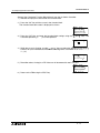
Please tick the box of your choice
What condition did the manual arrive in?
Good
Minor damage
Will you be using a folder to store the manual?
Yes
No
What do you think to the manual presentation?
Tidy
Unfriendly
Are the explanations understandable?
Yes
Not too bad
Unusable
Unusable
Which explanation was most difficult to understand: ..................................................................
....................................................................................................................................................
Are there any diagrams which are not clear?
Yes
No
If so,which: ..................................................................................................................................
What do you think to the manual layout?
Good
Not too bad
Unhelpful
If there one thing you would like to see improved, what is it? .....................................................
....................................................................................................................................................
....................................................................................................................................................
Could you find the information you required easily using the index and/or the contents, if
possible please identify your experience: ...................................................................................
....................................................................................................................................................
....................................................................................................................................................
....................................................................................................................................................
....................................................................................................................................................
Do you have any comments in general about the Mitsubishi manuals? .....................................
....................................................................................................................................................
....................................................................................................................................................
....................................................................................................................................................
....................................................................................................................................................
Thank you for taking the time to fill out this questionnaire. We hope you found both the product
and this manual easy to use.
ii
α2 Simple Application Controllers
Guidelines for the safety of the user and protection of
controllers
α2 Simple Application
This manual provides information for the use of α2 Simple Application controllers. The manual
has been written to be used by trained and competent personnel. The definition of such a
person or persons is as follows;
a) Any engineer who is responsible for the planning, design and construction of automatic
equipment using the product associated with this manual should be of a competent
nature, trained and qualified to the local and national standards required to fulfill that
role. These engineers should be fully aware of all aspects of safety with regards to
automated equipment.
b) Any commissioning or service engineer must be of a competent nature, trained and
qualified to the local and national standards required to fulfill that job. These engineers
should also be trained in the use and maintenance of the completed product. This
includes being completely familiar with all associated documentation for the said product.
All maintenance should be carried out in accordance with established safety practices.
c) All operators of the completed equipment (see Note) should be trained to use this
product in a safe manner in compliance to established safety practices. The operators
should also be familiar with documentation which is associated with the operation of the
completed equipment.
Note : The term ‘completed equipment’ refers to a third party constructed device which
contains or uses the product associated with this manual.
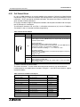
Notes on the Symbols Used in this Manual
At various times throughout this manual certain symbols will be used to highlight points of
information which are intended to ensure the users personal safety and protect the integrity of
equipment. Whenever any of the following symbols are encountered its associated note must
be read and understood. Each of the symbols used will now be listed with a brief description of
its meaning.
Hardware warnings
1 ) Indicates that the identified danger WILL cause physical and property damage.
2 ) Indicates that the identified danger could POSSIBLY cause physical and property
damage.
3 ) Indicates a point of further interest or further explanation.
Software warning
4 ) Indicates special care must be taken when using this element of software.
5 ) Indicates a special point which the user of the associate software element should
be aware of.
6 ) Indicates a point of interest or further explanation.
iii
α2 Simple Application Controllers
iv
α2 Simple Application Controllers
Table of Contents
Safety Guidelines ................................................................................ iii
1. Introduction ............................................................................... 1-1
1.1 Special Features of the Controller ........................................................ 1-1
1.2 Model Name .......................................................................................... 1-2
1.3 Version Up List ...................................................................................... 1-3
1.4 Applicable Programming Software ........................................................ 1-3
2. Function Block Programming .................................................... 2-1
2.1 Block Type and the FBD base .............................................................. 2-1
2.1.1 Inputs ........................................................................................... 2-2
2.1.2 Front Panel Keys .......................................................................... 2-2
2.1.3 System Memory Bits .................................................................... 2-3
2.1.4 Function Blocks ............................................................................ 2-3
2.1.5 Outputs ........................................................................................ 2-4
2.1.6 Function Block Diagram (FBD) base ............................................ 2-4
2.2 Programming Methods .......................................................................... 2-5
2.2.1 Direct Programming ..................................................................... 2-5
2.2.2 AL-PCS/WIN-E Programming Software Ver. 2.50 and upwards .. 2-5
3. System Menu ............................................................................ 3-1
3.1 Menu Options Instructions .................................................................... 3-1
3.2 The Stop Mode ..................................................................................... 3-2
3.2.1 Top Menu ..................................................................................... 3-2
3.2.2 The “Others... ............................................................................... 3-6
3.3 The Run Mode Top Menu ................................................................... 3-12
3.4 The Edit Menu ..................................................................................... 3-15
3.5 The Function Block Edit Menu ............................................................ 3-15
3.6 Option Screen Setup ........................................................................... 3-16
3.6.1 ProgEdit ..................................................................................... 3-16
3.6.2 Change the Language Setting ................................................... 3-16
3.6.3 ClockSET ................................................................................... 3-16
3.6.4 RadioClock - DCF77 Decoding .................................................. 3-17
3.6.5 SummerTime .............................................................................. 3-18
3.6.6 DispPass .................................................................................... 3-19
3.6.7 Password ................................................................................... 3-20
3.6.8 Enhanced User Program Protection (Version 2.20 or later) ....... 3-20
3.6.9 Serial Com ................................................................................. 3-22
3.6.10 Memory cassette ...................................................................... 3-23
3.6.11 Analog Inputs ........................................................................... 3-24
3.7 LCD Displays ...................................................................................... 3-25
3.7.1 Image Table ............................................................................... 3-25
3.7.2 LCD Function ............................................................................. 3-25
v
α2 Series Applications Controller
3.8 Block Items ......................................................................................... 3-26
3.8.1 Input Blocks ............................................................................... 3-26
3.8.2 Function Blocks .......................................................................... 3-26
3.8.3 Output Blocks ............................................................................. 3-26
3.8.4 Connected Blocks ...................................................................... 3-26
4. Direct Programming .................................................................. 4-1
4.1 Block Availability ................................................................................... 4-1
4.2 Connecting Blocks ................................................................................ 4-1
4.2.1 To connect the blocks from the left (signal provider) block to
right (signal receiver) block. ......................................................... 4-1
4.2.2 To connect the blocks from the right (signal receiver) block to
left (signal provider) block. ........................................................... 4-2
4.3 Disconnect Two Blocks ......................................................................... 4-2
4.4 Methods to Create a Function Block ..................................................... 4-3
4.4.1 New FB ........................................................................................ 4-3
4.4.2 AddFB .......................................................................................... 4-3
4.5 Function Block Editing .......................................................................... 4-3
4.5.1 Setup Function Block ................................................................... 4-3
4.5.2 Change No. (of a Function Block) ................................................ 4-3
4.5.3 Delete FB ..................................................................................... 4-3
4.6 Movement between Function Blocks .................................................... 4-4
4.6.1 Movement Between Unconnected Blocks .................................... 4-4
4.6.2 Movement Between Connected Blocks ....................................... 4-4
4.6.3 The Jump Command .................................................................... 4-4
4.7 Using Keys as Inputs ............................................................................ 4-4
4.8 The Monitor Mode ................................................................................. 4-5
4.8.1 Monitor/Update Function Block Values ........................................ 4-5
4.8.2 Forcing Outputs ON/OFF ............................................................. 4-6
4.8.3 Add/Delete Function Blocks in the Monitor Mode ........................ 4-6
5. The Logic Function Blocks ........................................................ 5-1
5.1 The AND Block ..................................................................................... 5-2
5.2 The OR Block ........................................................................................ 5-3
5.3 The NOT Block ..................................................................................... 5-4
5.4 The XOR Block (Exclusive OR) ............................................................ 5-4
5.5 The NAND Block (Not AND) ................................................................. 5-5
5.6 The NOR Block (Not OR) ...................................................................... 5-6
vi
α2 Series Applications Controller
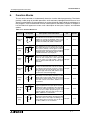
6. Function Blocks ......................................................................... 6-1
6.1 Definitions ............................................................................................. 6-8
6.2 Abbreviations ........................................................................................ 6-8
6.3 Boolean block ....................................................................................... 6-9
6.4 Set/Reset Block .................................................................................. 6-11
6.5 Pulse Block ......................................................................................... 6-13
6.6 Alternate Block .................................................................................... 6-15
6.7 Delay Block ......................................................................................... 6-16
6.8 One Shot Block ................................................................................... 6-18
6.9 Flicker Block ........................................................................................ 6-20
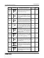
6.10 TimeSW Block .................................................................................. 6-23
6.10.1 Setting the First Time Switch ................................................... 6-23
6.10.2 For the Date operation: ............................................................ 6-24
6.10.3 For the Weekly Operation: ....................................................... 6-24
6.10.4 To Enter New Time Switches ................................................... 6-24
6.10.5 To Edit Time Switches ............................................................. 6-25
6.10.6 To Delete Time Switch Data .................................................... 6-25
6.11 Counter Block ................................................................................... 6-26
6.12 Up/Down Counter Block .................................................................... 6-27
6.13 Compare Block ................................................................................. 6-29
6.14 Analog Output ................................................................................... 6-31
6.15 OFFSET Block .................................................................................. 6-34
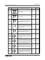
6.16 Display Block .................................................................................... 6-37
6.16.1 Displaying Data Onscreen ....................................................... 6-37
6.16.2 Editing Data Onscreen ............................................................. 6-38
6.17 Zone Compare Block ........................................................................ 6-41
6.18 Schmitt Trigger Block ........................................................................ 6-43
6.19 Hour Meter Block .............................................................................. 6-46
6.20 Speed Detect Block .......................................................................... 6-48
6.21 Pulse Width Modulation .................................................................... 6-53
6.22 PID Block .......................................................................................... 6-55
6.22.1 Parameter List and PID Details. ............................................... 6-56
6.22.2 Setting the Input Values, SV and PV ....................................... 6-58
6.22.3 Setting the Function Block Parameters .................................... 6-58
6.22.4 Limiting the Manipulated Value ................................................ 6-61
6.22.5 Setting KP, TI, and TD with Auto-tuning .................................. 6-62
6.22.6 PID Troubleshooting ................................................................ 6-64
6.22.7 Error Codes .............................................................................. 6-64
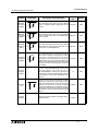
6.23 Retentive Alternate Block .................................................................. 6-69
6.24 Addition Block ................................................................................... 6-70
6.25 Subtraction Block .............................................................................. 6-71
6.26 Multiplication Block ........................................................................... 6-72
6.27 Division Block .................................................................................... 6-73
6.28 Calculation Block .............................................................................. 6-74
6.29 Shift Block ......................................................................................... 6-76
vii
α2 Series Applications Controller
6.30 GSM/SMS Block ............................................................................... 6-78
6.30.1 Input Signal .............................................................................. 6-80
6.30.2 Output Signal ........................................................................... 6-80
6.30.3 Word Output ............................................................................. 6-80
6.30.4 Short Message Service (SMS) ................................................ 6-81
6.30.5 Comment/Signal Number ......................................................... 6-81
6.30.6 Setting ...................................................................................... 6-81
6.30.7 Destination ............................................................................... 6-81
6.30.8 SMS Setting Dialog Box ........................................................... 6-82
6.30.9 SMS Service Center ................................................................ 6-82
6.30.10 Valid Period ............................................................................ 6-82
6.30.11 Destination ............................................................................. 6-82
6.30.12 Error Messages ...................................................................... 6-83
6.31 Short Message Receiving Block ....................................................... 6-89
6.31.1 Authentication and Security ..................................................... 6-91
6.31.2 SM Commands ........................................................................ 6-92
6.31.3 Report Short Message Handling .............................................. 6-93
6.31.4 SMR (Short Message Receiving) Setting Dialog Box .............. 6-94
6.32 Call Detect Block ............................................................................... 6-95
6.32.1 Number of RING ...................................................................... 6-96
6.33 Random One Shot Block .................................................................. 6-97
6.34 Delayed One Shot Block ................................................................... 6-99
6.35 Delayed Alternate Block .................................................................. 6-102
6.36 Retentive Set Reset Block .............................................................. 6-104
6.37 Control Display Manager ................................................................ 6-106
6.37.1 Operation Image: ................................................................... 6-107
6.37.2 To Set Display Manager: ........................................................ 6-108
6.38 Connect Block ................................................................................. 6-114
7. Let’s Make a Program ............................................................... 7-1
7.1 Option Settings ..................................................................................... 7-1
7.2 The Function Block Diagram ................................................................. 7-1
7.3 Input the Program ................................................................................. 7-2
7.3.1 Adding Function Blocks by the Left to Right method
(Section 4.2.1) ............................................................................. 7-2
7.3.2 Scroll through the Function Blocks by Number (Section 4.6.1) .... 7-3
7.3.3 Use the Jump Command (Section 4.6.3) ..................................... 7-3
7.3.4 Use the NewFB command ........................................................... 7-4
7.3.5 Connect the Function Blocks from Right to Left (Section 4.2.2) .. 7-4
7.4 Set up the Function Block Parameters (Section 4.5.1) ......................... 7-5
7.5 Exit the Function Block Diagram board ................................................. 7-6
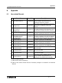
8. Appendix ................................................................................... 8-1
8.1 Associated Manuals .............................................................................. 8-1
8.2 System Keys ......................................................................................... 8-2
8.3 System Bits ........................................................................................... 8-2
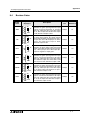
8.4 Boolean Gates ...................................................................................... 8-3
8.5 PID Formulas ........................................................................................ 8-9
viii
α2 Simple Application Controllers
1.
Introduction 1
Introduction
The α2 Series Controllers provides supervisory control for use in the home, office, factory or
wherever you need it. The α 2 Series Controllers offers flexible I/O control for varied
applications:
Applications
The α2 Series is designed to be used for automatic applications including:
- Lighting, air-conditioning or watering control
- Opening and closing gates
- Security systems
- Domestic systems
- Temperature control
However, the α2 Series Controllers is not designed to be used in the following applications:
- Applications where high reliabilities such as nuclear power control, railway facilities,
airline facilities, vehicles, combustion equipment and medical equipment are required.
- Applications in life critical situations
Please contact a Mitsubishi distributor for more information.
1.1
Special Features of the Controller
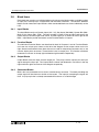
1 ) Display messages and Function Block data
The α2 Series Controller can display the state of operation and the status of an alarm on
the LCD screen as a message. The α2 Series Controller allows the values of timers and
counters to be changed while in RUN mode.
- Total characters on LCD display: 12 characters x 4 lines
- Display items: Message, values (current or set) of timers and counters, analog
values, etc.
2 ) Program Input
The user can program directly from the front panel or use the windows based
AL-PCS/WIN-E programming software Ver. 2.00 and upwards. Pictorial representations of
data are used to connect function blocks in both methods. Please refer to the α Software
Manual for details on AL-PCS/WIN-E.
3 ) Enhancement of clock function
The calendar timer function can switch inputs to time-dependent controls on a daily or
weekly basis.
4 ) Analog input, 0-10V/0-500
The DC input type for the α2 Series accepts 0-10V signals with a digital range of 0-500
(50 divisions per volt).
5 ) High Speed Counter (max. 1kHz)
The α2 Series Controller can have two dedicated high speed counters when using
AL2-4EX EI1 and EI2.
1-1
α2 Simple Application Controllers
Introduction 1
6 ) High current output
The Relay outputs can handle 8A per common (COM) in the main units: AL2-10MR-*
(O01-6); AL2-14MR-* (O01-6); AL2-24MR-D (O01-04). Transistor outputs are 1A/point in
the extension module.
7 ) GSM Function (AL2-14MR-*, AL2-24MR-*)
The α 2 Series Controller uses GSM to send a short message to a mobile phone or a
dedicated
E-mail account via a standard service provider. By receiving a short message FB bit
outputs or word output values can be changed.
8 ) Dedicated Protocol (AL2-14MR-*, AL2-24MR-*)
The α2 Series Controllers introduces this concept allowing the user to monitor, modify and
enter current and set values in Function Blocks from a personal computer.
9 ) Built-in EEPROM
The built in EEPROM stores the user program non-volatile.
10 )Supports 7 languages
The system supports the following languages: English, German, French, Italian, Spanish,
Swedish and Russian*1.
*1 Ver.3.00 or later
11 ) LCD Screen
Enhanced LCD screen size displays data more clearly and enables the α 2 Series
Controller to display bar graphs and other new data representations.
12 )Increased Memory
The CPU memory for the α 2 Series Controller can store 5 kbyte of programming or a
maximum of 200 function blocks.
This manual will describe front panel programming of the α2 Series Controllers, the powerful
function block capabilities, and the functions of the front panel keys.
1.2
Model Name
The α2 Series Controllers can be identified using the following format:
AL2- ** M R - *
AL2 - Series Controller
** - Total number of I/O
M - Main Unit
A - 100-240 VAC
D - 24 VDC
R - Relay Type Output
1-2
α2 Simple Application Controllers
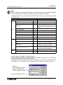
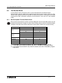
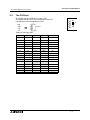
1.3
Introduction 1
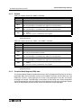
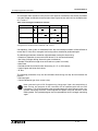
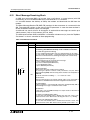
Version Up List
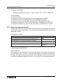
Table 1.1: History of α2 Series
Version
1.4
Description
V1.00
First product
V2.00
Supports the following points.
• AL2-2DA, AL2-2PT-ADP, AL2-2TC-ADP modules
• New function blocks
AO [Analog output] and PID [PID control]
• DCF77 Radio clock
V2.20
Supports the following points.
• New function blocks
SMR[Short Message Receiving] and CD[Call Detect]
• Enhanced User Program Protection
• Enhanced Daylight Saving Time Setup
• Enhanced Dedicated Protocol Communication
• GSM SIM PIN
• Modem Initialization String
V3.00
Supports the following points.
• Hour Meter backs up by EEPROM (No.197 - 200)
• Display Buffer Read by Dedicated Protocol
• Russian language addition
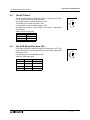
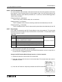
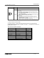
Applicable Programming Software
Table 1.2: Applicable Programming Software
α2 Version
Programming Software (AL-PCS/WIN-E) Version
V1.00
V2.00 or later
V2.00
V2.30 or later
V2.20
V2.40 or later
V3.00
V2.50 or later
Note;
• AL-PCS/WIN-E versions lower than V2.00, do not communicate with the α2 series.
• AL-PCS/WIN-E versions lower than V2.30, do not use the AL2-2DA, AL2-2PT-ADP or
AL2-2TC-ADP.
1-3
α2 Simple Application Controllers
Introduction 1
MEMO
1-4
α2 Simple Application Controllers
2.
Function Block Programming 2
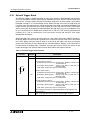
Function Block Programming
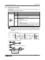
The α2 Series Controller is programmed with a user-friendly method of combining specialpurpose dedicated function blocks. The task is broken down into various stages which can be
represented by a number of function blocks. Function Block Programming simplifies
application representation but ensures complete process control. The program can be
developed in very simple steps but even a complex task can be represented in this way. For
ease of use, the function blocks have been preprogrammed to perform certain tasks yet offer
flexibility to be tailored to individual requirements.
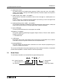
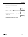
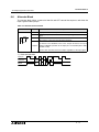
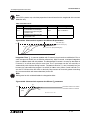
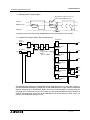
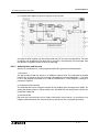
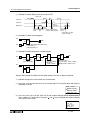
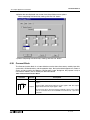
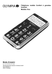
Figure 1.1: Principle of Function Block Programming
S B001
C OS
I01
O01
One Shot
I02
I03
1 B002
2
3 OR
4
S B003
R SR
O02
Set/Reset
O03
I0n
O0n
OR
SR
OS
- Input n
- Output n
- OR Boolean Function Block
- Set/Reset Function Block
- One Shot Function Block
The user can build a complex circuit in small, easy steps by starting at the input and working
forward in a logical manner. The α 2 will gather and process information and provide the
necessary control for the application according to the system algorithm. Each function block
provides specific control parameters, accessible by the user, to tailor each program for
complete application suitability. The function blocks are connected together to form a circuit
using the Function Block Diagram (FBD.)
2.1
Block Type and the FBD base
There are seven sets of items that can be used in the function block program: Inputs, Front
Panel Keys, System Memory Bits, Logic Blocks, Function Blocks, User-defined Function
Blocks and Outputs. A brief description of each follows.
2-1
α2 Simple Application Controllers
2.1.1
Function Block Programming 2
Inputs
The α 2 Series Controller will accept both digital (On/Off) and analog (mV value based)
electrical information through the system Inputs. Please refer to the α2 Hardware Manual for
electrical information, wiring diagrams and input specifications. Depending on the specific
controller there are either 14 or 24 input version types of the α2 Series Controller. The Inputs
are referenced to I01, I02, ..., I15.
Table 2.1: Input type for the AL2-10MR-* Controller
Input
Input Number
Signal
I01 - I06
Analog
(AL2-10M*-D)
A01 - A06
Description
Maximum of 6 Inputs are allocated for use.
Maximum of 6 Analog inputs are allocated for use on input I01 to I06.
Table 2.2: Input type for the AL2-14MR-*, AL2-24MR-* Controller
2.1.2
Input
Input Number
Description
Signal
I01 - I15
AS-i
E01 - E04
Maximum of 4 AS-interface inputs are allocated for use.
Analog
(AL2-**M*-D)
A01 - A08
Maximum of 8 Analog inputs are allocated for use on input I01 to I08.
Extension
EI01 - EI04
Maximum of 4 Extension inputs are allocated for use.
Maximum of 15 Inputs are allocated for use.
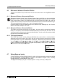
Front Panel Keys
The front panel keys can enter data into the program memory, move through menus or
programs, select programming options, or be used as extra inputs when the program is
running. There are eight keys which are referenced as K01 - K08.
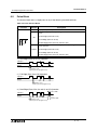
Table 2.3: Front panel keys for the α2 Series Controller
Key Name
Key number
Key Function
OK
K01
Used to enter menu options, confirm data entry, and manually force
inputs ON/OFF in the monitor function.
ESC
K02
Used to cancel an operation, move to a higher level screen, or to move
to a new menu.
“+”
K03
Used to connect (or “add”) function blocks, increase Direct Set input
values or times, or move through programs or menus.
“-”
K04
Used to disconnect function blocks, decrease Direct Set values or
times, or move through programs or menus.
( )
K05
Scroll up through menu options (menus, keys, FB, Inputs, Outputs,
etc.)
( )
K06
Scroll down through menu options (menus, keys, FB, Inputs, Outputs,
etc.)
( )
K07
Move to the right on the LCD display, FB program, or Jump command
( )
K08
Move to the left on the LCD display, FB program, or Jump command
If the front panel keys are used as auxiliary inputs on the FBD, their primary function, as front
panel display navigators, will be disabled.
2-2
α2 Simple Application Controllers
2.1.3
Function Block Programming 2
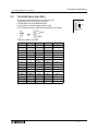
System Memory Bits
These System Memory Bits can provide predefined signals - Always On, Always Off, 0.5
second On, 0.5 second Off, or provide information about the Real Time Clock time or errors
etc. There are 24 Memory bits that are referenced as M01, M02, ... M24.
Table 2.4: System Bits for the α2 Series Controller
System
Bit
AL2-10M AL2-14M
AL2-24M
M01
Always “ON”.
3
3
M02
Always “OFF”.
3
3
M03
Alternate - 0.5 seconds “ON”, 0.5 seconds “OFF”.
3
3
M04
“ON” when Real Time Clock data error occurs.
3
3
M05
“ON” when Summer time schedule is activated.
3
3
M06
“ON” when AS-interface communication Error occurs.
−
3
M07
“ON” when communication Error caused by AS-interface power failure
occurs.
−
3
M08
Pulses “ON” when Stop mode turns to Run mode in the α2 Series.
3
3
M09
Pulses “OFF” when Stop mode turns to Run mode in the α2 Series.
3
3
M10
“ON” during DCF77 decoding
3
3
M11
Pulses “ON” when DCF77 finishes decoding without an error
3
3
M12
“ON” when CD (DCD) signal is turned ON (receiving CD signal from
the modem.)
−
3
M13
“ON” when it is possible to access the GSM network.
−
3
M14
“ON” when the α2 series controller is accessed via GSM
−
3
M15
“ON” when DCF77 finishes decoding with an error
3
3
M16
“ON” when external power for the 2DA board is on
−
3
M17
“ON” when there is a sensor defect at I01
3
3
M18
“ON” when there is a sensor defect at I02
3
3
M19
“ON” when there is a sensor defect at I03
3
3
M20
“ON” when there is a sensor defect at I04
3
3
M21
“ON” when there is a sensor defect at I05
3
3
M22
“ON” when there is a sensor defect at I06
3
3
M23
“ON” when there is a sensor defect at I07
−
3
“ON” when there is a sensor defect at I08
−
3
M24
2.1.4
Description
Function Blocks
Programming the α 2 Series Controller is based upon the combination of different function
blocks. They process the information received from the previously mentioned inputs and
control the system Outputs. They can also provide input signals or information to other function
blocks using word outputs pins. To make programming easier, the Function Blocks have all
been preprogrammed. However, parameters within each function block dialog box can be set
according to the intended application. There are 40 Function Blocks available, they are
described in detail throughout Chapters 5 and 6.
2-3
α2 Simple Application Controllers
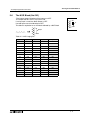
2.1.5
Function Block Programming 2
Outputs
Table 2.5: Outputs for the AL2-10MR-* Controller
Outputs
O01 - 04
N01
Description
Signal output
No
N02*1
ON: The back light is “OFF” in LCD.
OFF: The back light is controlled by the “Light Time” setting in Menu.
N03*1
ON: The back light is “ON” in LCD.
OFF: The back light is controlled by the “Light Time” setting in Menu.
ON:
N04
The user screen is controlled by the setting of “Display Manager” with AL-PCS/
WIN-E.
OFF: The user screen is controlled by user program.
Note: *1 When both N02 and N03 are ON and hence the back light is “ON” because N03 is
given the priority.
Table 2.6: Outputs for the AL2-14MR-*, AL2-24MR-* Controller
Outputs
Description
O01 - 09
Signal output
A01 - 04
AS-interface Output
EO1 - E04
N01
Extension Output
ON: Disconnected to AS-interface network
OFF: Connect to AS-interface network
N02*1
ON: The back light is “OFF” in LCD.
OFF: The back light is controlled by the “Light Time” setting in Menu.
N03*1
ON: The back light is “ON” in LCD.
OFF: The back light is controlled by the “Light Time” setting in Menu.
ON:
N04
The user screen is controlled by the setting of “Display Manager” with AL-PCS/
WIN-E.
OFF: The user screen is controlled by user program.
Note: *1 When both N02 and N03 are ON and hence the back light is “ON” because N03 is
given the priority.
2.1.6
Function Block Diagram (FBD) base
The Function Block Diagram provides the base for which all programming actions for the α2 is
performed. Both the α2 controller and the AL-PCS/WIN-E software use the FBD base. The
FBD base contains a Title rectangle on the top, Input rectangles on the left and Output
rectangles on the right. The FBD base is also known as FBD wiring area. All the components
should be placed only within the FBD base rectangle except for the input and output signals
which can be placed in the FBD wiring area or in the Input or Output rectangles.
2-4
α2 Simple Application Controllers
2.2
Programming Methods
2.2.1
Direct Programming
Function Block Programming 2
Direct Programming uses the keys on the front panel to create the program and enter any
required data values. The method for Direct Programming is explained in Chapter 4 of this
manual.
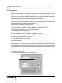
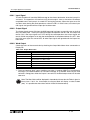
2.2.2
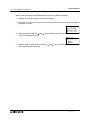
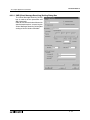
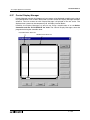
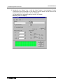
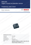
AL-PCS/WIN-E Programming Software Ver. 2.50 and upwards
This windows based software allows the user to drag and drop the desired Function Block
icons onto the FBD base and construct a program. The program is downloaded to the α2
controller via the AL-232CAB cable. The visual on-screen connections make the software easy
to grasp for beginners and experienced users alike. The AL-PCS/WIN-E Programming
Software is fully explained in the α Software Manual (JY992D74001).
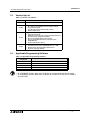
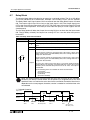
Figure 2.1: AL-PCS/WIN-E Programming Software Ver. 2.50 and upwards
Note: Do not simultaneously program the α 2 Series Controller from the direct
programming keys and AL-PCS/WIN-E Ver. 2.00 methods as this may result in
unexpected operation and possibly cause harm.
2-5
α2 Simple Application Controllers
Function Block Programming 2
MEMO
2-6
α2 Simple Application Controllers
3.
System Menu
3.1
Menu Options Instructions
System Menu 3
There are Systems Menus to help guide the user through the options available in the α2. The
TopMenu has a Run Mode that is accessed while the α2 is in operation or a Stop Mode that is
accessed when the α2 is idle.
The Edit Menu and the Function Block Edit Menu can be accessed when in either ProgEdit or
Monitor. These menus can be used to create and/or change programs steps or values.
Use the “OK” key to enter a programming option or to enter data into memory.
Set all the data on the screen before using the “OK” key to write the data to the system
memory. If there are multiple data screens in an option, enter the required data and accept
each screen with the “OK” key.
The “ESC” key will move the screen back to a higher menu option. It will cancel any data input
that has not been accepted with the “OK” key.
Note:
Use the “ESC” key to exit the option to the higher menu; at times, it will be necessary to press
the “ESC” key a number of times to move through multiple programming layers.
3-1
α2 Simple Application Controllers
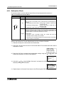
3.2
The Stop Mode
3.2.1
Top Menu
System Menu 3
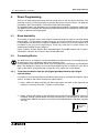
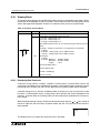
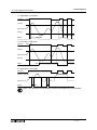
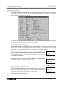
When the α2 is first turned On, the Input/Output Image Table will appear. Press the “OK” and
“ESC” keys simultaneously to move to the TopMenu.
(If the TopMenu cannot be accessed the Menu Key has been set to “Not Use”),
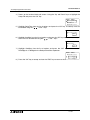
• Run:
Places the controller in Run mode.
• Parameter:
Provides a simple method to edit Time Switches (TSm), Short Message Receive (SMRm)
and Call Detect (CDm) from the Top Menu.
• ProgEdit:
Allows program editing/creation on the display using the front panel keys. The current
memory will be overwritten as changes are made to the program. Programs can be saved
on an AL2-EEPROM-2 memory cassette or in the AL-PCS/WIN-E software Ver. 2.00 or
later.
• ClockSet:
Set the Real Time Clock or input a daily clock adjustment. The RadioClock function is also
available here.
• LANGUAGE:
Choose from 7 onscreen languages: English, German, French, Italian, Spanish, Swedish,
or Russian*1.
• OTHERS...
*1 Ver. 3.00 or later
3-2
α2 Simple Application Controllers
System Menu 3
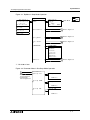
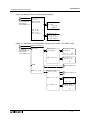
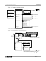
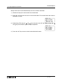
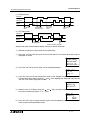
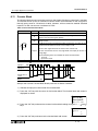
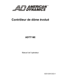
Figure 3.1: TopMenu in Stop Mode Operation
OK
ESC
T o p Me n u
10 : 19 F r i
I : •2• •5• • •9
•1• • •5
O: 1• •4• • •8
E:1• •4
A : • 23 •
Ru n
Ru n / S t o p
S t op
→R u n
OK
or
ESC
Run Mode
P a r a me t e r
1
Refer to Figure 3.2
2
P r o gEd i t
3
Refer to Figure 3.3
4
C l o c kSe t
5
Refer to Figure 3.4
6
EI :1• •4
EO : • 2 3 •
LANGUAGE
L ANGUAGE
En g l i s h
G e r ma n
F r ench
I t a l i an
Sp a n i s h
Sw e d i s h
R u s s i a n *1
7
Refer to Figure 3.5
8
Ot he r s . . .
*1 Ver. 3.00 or later
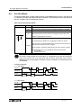
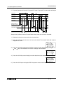
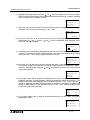
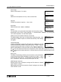
Figure 3.2: Parameter Menu in Run/Stop Mode Operation
1
2
P a r a me t e r
Se t u p TS
- In Stop mode,
refer to Figure 3.1
- In Run mode,
refer to Figure 3.11
Se t u p TS
NoDa t a
S e t u p SMR
S e t u p SMR
NoDa t a
S e t u p CD
S e t u p CD
NoDa t a
3-3
α2 Simple Application Controllers
System Menu 3
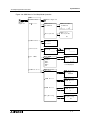
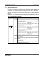
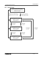
Figure 3.3: ProgEdit Menu in Stop Mode Operation
Adding Function Blocks
P r og r a mSc r een
3
4
01
01
Refer to
Figure 3.1
In
FB Se l e c t
AND
Add FB
O 01
Ca l l De t e c t m
Connect EO 04
(OK, ESC, +, -,
, , , )
*1
*2
(+) or (-) Skips to
the next topic
*3
F B P a r a me t e r
S e t u p F B *1
C h a n g e N o *2
D e l e t e F B *3
Function Block Specific
Changes Function Block Number
Deletes Function Block from
FBD
E d i t Me n u
Bl ock
0 FB
P r o gS i z e
Me mo r y
0%
J u mp
J u mp
M I O K E *4
M 0 1 *5
S y s t e mB i t
NewFB
FB Se l e c t
AND
Ex i t
Ca l l De t e c t m
Mn e mo n i c
I 01
*4
*5
Select the following category by pressing " and " keys.
- M ↔ I ↔ O ↔ K ↔ E ↔ A ↔ N ↔ EI ↔ EO ↔ B
Select the jump target by pressing " and " keys.
3-4
α2 Simple Application Controllers
System Menu 3
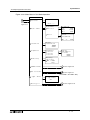
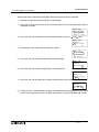
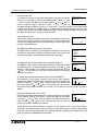
Figure 3.4: ClockSet Menu in Run/Stop Mode Operation
5
6
C l o c kSe t
C l o c kSe t
- In Stop mode,
refer to Figure 3.1
- In Run mode,
refer to Figure 3.11
C l o c kSe t
d d / mm / y y y y
29 / 06 / 2003
7 : 5 9 Su n
Co r r e c t
Co r r e c t
0 . 00s / d
GMT Z o n e
C l o c kSe t
GMT Z o n e
0 h 0 0m
Ra d i oC l o c k
Ra d i oC l o c k
Ra d i oC l o c k
I npu t
Ra d i oC l o c k
No t Us e
DC F 7 7
*1
Ra d i oC l o c k
I npu t
I 01
T i me D i f f e r
*1
Ma n u a l
*1
Ra d i oC l o c k
T i me D i f f e r
0 . 0h r s
Ma n u a l
Star t
OK
*1
or
Ac t .
E SC
When DCF77 Radio Clock menu is not set,
these items will not be displayed.
Caution
When setting the Real Time Clock or inputting a daily clock adjustment to the following menu
functions, please change the mode to Stop.
• ClockSet in ClockSet Menu
• Correct in ClockSet Menu
3-5
α2 Simple Application Controllers
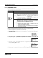
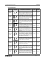
3.2.2
System Menu 3
The “Others...
•
•
•
•
•
•
•
•
•
•
•
Version:
Displays CPU Version of the α2 Series Controller.
Scan Time:
Monitor the Current, Maximum, or Minimum program scan times. Upon controller reset
current, Maximum and Minimum values for scan times are reset to 0.
Password:
Restrict entry to the ProgEdit and Monitor mode with a four digit password.
DispPass:
Set up to three Passwords for Display function blocks.
Menu Key:
Two settings are possible, “Not Use” or “OK + ESC”. “Not Use” is designed so that
unauthorized people cannot access the α2 Top Menu in Run mode. If the “OK + ESC” key
setting is selected, simultaneously depress the “OK” and the “ESC” keys to access the Top
Menu.
Summertime:
Choose the preferred daylight savings time: Cancel, Manual On, Date Type, UK type, US
type, or EU type.
Serial Com:
Choose the type of communication to be used for the right hand side serial communication
port - Not Use, Modem, GSM or Other Com.
Light Time:
Set the backlight off delay time.
Analog In:
Indicates the current modes (Normal, TC or PT100) of the Analog inputs and the menu
item for changing the temperature scale (°C or °F) that the controller displays. Also
contains the menu items for calibration and offset adjust.
ProgClear:
Completely clears the system memory including Password protected programs. Only the
active memory is cleared, i.e. if a memory cassette is installed, the memory cassette
program will be erased but the controller memory will be retained.
ProgTran. (only appears if a cassette is installed):
Verify, Cassette Æ (the cassette writes to the α2), Cassette Å(the cassette reads from
the α2), and ProtectSW are the options available.
3-6
α2 Simple Application Controllers
System Menu 3
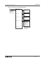
Figure 3.5: Others Menu in Stop Mode Operation
Ot he r s . . .
Ve r s i o n
7
8
Ve r s i o n
Refer to
Figure 3.1
Ve r * . * *
Sc an
T i me
S c a n T i me
Mo n i t o r
S c a n T i me
Cu r .
0ms
Ma x .
1 2ms
Mi n
0ms
Re s e t
Re s e t
S c a n T i me
OK
Pa s swo r d
D i s pPa s s
Me n u
Ke y
D i s pPa s s
Leve l 1
Leve l 2
Leve l 3
Se t u p
D i s pPa s s
Leve l 1
Me n u K e y
No t Us e
ON + E SC
Ke y
9
Refer to Figure 3.6
10
11
Refer to Figure 3.7
12
C o m*1
*1
L i gh t
An a l o g
T i me
Se t u p
L i gh t
AL2-14MR-*, AL2-24MR-* Only
T i me
2m
13
Refer to Figure 3.10
14
In
P r o gC l e a r
E SC
Se t u p
Pa s swo r d
S u mme r T i me
Se r i a l
or
P r o g r am
C l ea r
OK
or
E SC
P r o g T r a n *2
*2
ProgTran menu is only displayed
when connecting AL2-EEPROM-2
memory cassette.
3-7
α2 Simple Application Controllers
System Menu 3
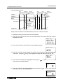
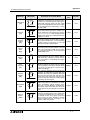
Figure 3.6: Summer Time in Run/Stop Mode Operation
9
10
- In Stop mode,
refer to Figure 3.5
- In Run mode,
refer to Figure 3.13
S u mme r T i me
Ca n c e l
Ma n u a l O n
Da t a T y p e
UK T y p e
US T y p e
EU T y p e
F r ee Type
S u mme r T i me
31 / 03
~30 / 10
+ 6 0m i n
S u mme r T i me
0 3 / 1 . Su n
~1 0 / 1 . Su n
0 2 : 0 0 6 0m i n
Figure 3.7: Serial Com in Run/Stop Mode Operation (AL2-14MR-*, AL2-24MR-* Only)
11
12
- In Stop mode,
refer to Figure 3.5
- In Run mode,
refer to Figure 3.13
S e r i a l C om
No t Us e
Mo d e m
Mo d e m I n i t
C o mma n d
D e l a y T i me
Mo d e m I n i t 0 1
C o mma n d
[
]
yz { | } ! " #$
Mo d e m I n i t
D e l a y T i me
0s
15
Refer to Figure 3.8
16
GSM
Ot he r
C om
O t h e r C om
C o m f o r ma t
S t a t i o n No
17
Refer to Figure 3.9
18
O t h e r Com
S t a t i o n No
No .
L i n kB l o c k
0
O t h e r Com
L i nk B l ock
0
3-8
α2 Simple Application Controllers
System Menu 3
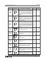
Figure 3.8: GSM Menu in Run/Stop Mode Operation
15
16
Refer to
Figure 3.7
GSM
C o mF o r ma t
GSM I n i t
17
Refer to Figure 3.9
18
GSM I n i t
C o mma n d
D e l a y T i me
GSM I n i t 0 1
C o mma n d
[
]
yz { | } ! " #$
GS M I n i t
D e l a y T i me
0s
GS M R e mo t e
GS M R e mo t e
Fo r b i t
Pe r mi t
P I N Co d e
P I N Co d e
Se t u p
****
Arrow key
P I N Co d e
Se t u p
" **** "
Arrow key
Se t
SMS
GSM S t a t u s
S e t SMS
SMSC 1
SMSC 2
DA 1
DA 2
DA 3
VP
GSM S t a t u s
St a t us
S e t SMS
01
SMSC 1
[
]
9 + - ( ) 0 1 2 3*
* In Run mode, this line
is not displayed.
GSM S t a t u s
S t a t us
0 0 0 0H
CME E r r o r
GSM S t a t u s
CME E r r o r
-1
CMS E r r o r
GSM S t a t u s
CMS E r r o r
-1
S i gS t r e n g
GSM S t a t u s
S i gS t r e n g
0%
3-9
α2 Simple Application Controllers
System Menu 3
Figure 3.9: ComFormat in Run/Stop Mode Operation
17
18
C o mF o r ma t
Da t a L e n g t h
- In Other Com,
refer to Figure 3.7
- In GSM,
refer to Figure 3.8
Da t a L e n g t h
8 b i ts
7 b i ts
Pa r i t y
Pa r i t y
No n e
Od d
Ev en
S t op
S t op b i t
1 b i t
2 b i ts
bi t
Ba u d r a t e
De f a u l t
Ba u d r a t e
3 0 0 b p s *1
6 0 0 b p s *1
1 2 0 0 b p s *1
2 4 0 0 b p s *1
4 8 0 0 b p s *1
9600 bps
19200 bps
*1
When setting for GSM,
300 to 4800 bps will not
be displayed.
3 - 10
α2 Simple Application Controllers
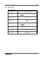
System Menu 3
Figure 3.10: Analog Inputs Setup Menu in Run/Stop Mode Operation.
13
14
An a l o g
I 0 1*1
In
- In Stop mode,
refer to Figure 3.5
- In Run mode,
refer to Figure 3.13
I 0 2 : T C*1
I 0 3 : P T 1 0 0 *1
:
:
:
:
:
:
:
I 0 8 *1
T e mp . S c a l e *4
I 0 1 *2
Mo d e
I 0 1 *2
N o r ma l
TC
PT 1 0 0
I 02
Mo d e *3
I 0 2 *2
N o r ma l
TC
PT 1 0 0
C a l i b r a t e *3
I 0 2 *2
Ca l i b r a t e
- 50 °C
450 °C
Of f se t
I 02
O f f s e t f i ne
0°C
f i ne
I 0 3 *2
N o r ma l
TC
PT 1 0 0
I 03
Mo d e *3
C a l i b r a t e *3
I 0 3 *2
Ca l i b r a t e
- 50 °C
200 °C
Of f se t
I 03
O f f s e t f i ne
0 . 0°C
f i ne
A n a l o g I n *4
T e mp . S c a l e
Ce l c i u s
Fah r en he i t
*1 This display example is set to I01-I08 as follows
I01, I04-I08: Normal setting (Default)
I02: TC setting
I03: PT100 setting
*2 In Run mode, this screen can not be displayed.
*3 In Run mode, these items can not be selected.
*4 In Run mode, this setting can not be changed.
3 - 11
α2 Simple Application Controllers
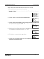
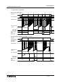
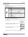
3.3
System Menu 3
The Run Mode Top Menu
When the α2 program is running, the LCD defaults to the Image Table screen. According to
the Menu Key setting, proceed to the Stop Mode of the Top Menu by using the “OK” and the
“ESC” keys or reset the controller by powering down.
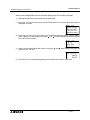
• Stop:
Takes the α2 out of Run mode.
• Setup TS:
Provides a simple method to edit Time Switches from the Top Menu.
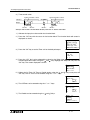
• Monitor:
Monitor the program settings while in the Run mode and perform limited editing to FB
parameters. The existing programming steps cannot be modified.
• ClockSet:
Set the Real Time Clock, input a daily clock adjustment or set the RadioClock function.
Caution
When setting the Real Time Clock or inputting a daily clock adjustment to the
following menu functions, please change the mode to Stop.
• ClockSet in ClockSet Menu
• Correct in ClockSet Menu
•
•
LANGUAGE:
Choose the on-screen language from English, German, French, Italian, Spanish, Swedish,
or Russian*1.
Others
*1 Ver. 3.00 or later
TOP MENU is not Displayed in Run Mode
The menu key should be operated to access the Top Menu. Push the keys “OK” and “ESC” at
the same time. If the menu call key is not set, use either the programming software to the Stop
mode or do the forced stop operation.
Caution
Perform the forced stop operation only after thoroughly checking that it is safe to do so.
Damage to the machine or controller or a safety issue could arise if the forced ON/OFF is
performed inappropriately.
If proper precautions are not taken, damage to the equipment or machine failure may occur.
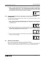
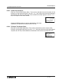
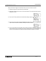
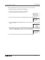
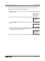
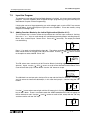
Forced Stop Operation
1) Turn the α2 series power supply off.
2) Turn the power ON again while pushing the “OK” and “ESC”
keys simultaneously.
The screen at right is displayed.
Ru n
→S t o p
The option to place the controller in Stop mode will be
available for approximately five seconds. Press the “OK” key
to enter the Stop Mode. If no key is pressed, the controller
will default back into the Run mode.
3) Press “ESC” key.
The “Run Mode Top Menu” is displayed.
3 - 12
α2 Simple Application Controllers
System Menu 3
Figure 3.11: TopMenu in Run Mode Operation
OK
ESC
T o p Me n u
10 : 19 F r i
I : •2• •5• • •9
•1• • •5
O: 1• •4• • •8
E:1• •4
A : • 23 •
Ru n / S t o p
Ru n
→S t o p
OK
or
ESC
S t op
P a r a me t e r
1
Refer to Figure 3.2
2
Mo n i t o r
19
Refer to Figure 3.12
20
C l o c kSe t
5
Refer to Figure 3.4
6
EI :1• •4
EO : • 2 3 •
Stop Mode
L ANGUAGE
En g l i s h
G e r ma n
F r ench
I t a l i an
Sp an i s h
Sw e d i s h
R u s s i a n *1
L ANGUAGE
21
Refer to Figure 3.13
22
Ot he r s
*1 Ver. 3.00 or later
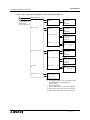
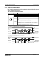
Figure 3.12: Monitor Screen in Run Mode Operation
Settings for Function Blocks
19
20
Refer to
Figure 3.11
Mon i t o r S c r een
01
B002
B003
In
003
01
=S P - I
In
RSR
F BS e t t i n g
Se t u p
02
Out
(OK, ESC, +, -,
, , , )
*1
Individual for each Function Block.
E d i t Me n u
Bl ack
4 FB
P r o gS i z e
Me mo r y
J u mp
Ex i t
1%
J u mp
M I O K E *2
M 0 1 *3
S y s t e mB i t
*2
*3
Select the following category by pressing " and " keys.
- M ↔ I ↔ O ↔ K ↔ E ↔ A ↔ N ↔ EI ↔ EO ↔ B
Select the jump target by pressing " and " keys.
3 - 13
α2 Simple Application Controllers
System Menu 3
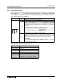
Figure 3.13: Others Menu in Run Mode Operation
Ot he r s . . .
21
22
Ve r s i o n
Ve r s i o n
Refer to
Figure 3.11
Ve r * . * *
Sc an
T i me
S c a n T i me
Mo n i t o r
Re s e t
S c a n T i me
Cu r .
0 ms
Ma x .
1 2 ms
Mi n
0 ms
Re s e t
S c a n T i me
OK
Pa s swo r d
D i s pPa s s
Me n u
Ke y
L i gh t
D i s pPa s s
Leve l 1
Leve l 2
Leve l 3
An a l o g
In
Se t u p
D i s pPa s s
Leve l 1
Me n u K e y
No t Us e
ON + E SC
Ke y
9
Refer to Figure 3.6
10
Com *
T i me
E SC
Se t u p
Pa s swo r d
S u mme r T i me
Se r i a l
or
11
Refer to Figure 3.7
12
Se t u p
L i g h t T i me
2m
* AL2-14MR-*, AL2-24MR-* Only
13
Refer to Figure 3.10
14
3 - 14
α2 Simple Application Controllers
3.4
System Menu 3
The Edit Menu
The Edit Menu can be entered when the α2 is in the ProgEdit or Monitor main programming
screen. If entering options or connecting FBs, these procedures have to be finished or
canceled before the Edit Menu can be entered. Press the “ESC” key at any place in the main
programming screen to enter the Edit Menu.
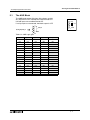
• ProgSize:
Shows the numbers of FBs used and percentage of program memory used.
• Jump:
Leads to a screen that shows available places to go in the program. “M” - system bits; “I” system Inputs; “O” - System Outputs; “K” - Keys (1-8); “E” - ASi Inputs; “A” - ASi Outputs;
“N” - Control bits; “EI” - External Board inputs; “EO” - External Board outputs; and “B” Function Blocks existing in the program. Choose the desired block with the arrow keys
and press the “OK” key to jump to that spot in the program.
• New FB:
Create a new Function Block from one of the available FBs.
• Exit: Exits to the Top Menu.
• Mnemonic:
Gives a mnemonic display of the current programming rung. Enter the programming mode
by pressing the “OK” key or return to the Edit Menu using the “ESC” key. (Not available in
Monitor Mode).
3.5
The Function Block Edit Menu
The Function Block Edit Menu can be entered only while in the ProgEdit or Monitor mode.
Move to the Function Block to edit and press the “OK” key when the Function Block number is
flashing.
• Setup FB:
Set variables in the Function Blocks for your application. See Chapter 6 for more details on
each Function Block’s Options. The logic functions in Chapter 5 do not have Setup
Options.
• Change No: Change the Function Block Number
• Delete FB: Delete Selected Function Block
3 - 15
α2 Simple Application Controllers
3.6
System Menu 3
Option Screen Setup
Various options have been provided for ease of use or for safety purposes. Please set as your
needs require. All of the options in this section can be accessed from either the Run or the
Stop Menu.
3.6.1
ProgEdit
Refer to chapter 4, Direct programming, for detailed instructions on programming the α2
Series Controller.
3.6.2
Change the Language Setting
1 ) Turn the α2 On.
2 ) Press the “OK” and “ESC” buttons simultaneously to go to the TopMenu or reset the
controller.
3 ) Scroll to the “LANGUAGE” option and press the “OK” key. The TopMenu entry
“LANGUAGE” is common for all languages.
4 ) Scroll to the desired language and press the “OK” key. The languages available are
English, German, French, Italian, Spanish, Swedish, and Russian*1.
5 ) Use the “ESC” key to exit to the Topmenu.
*1 Ver. 3.00 or later
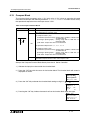
3.6.3
ClockSET
To set the Clock:
1 ) From the TopMenu, scroll to “ClockSet” and press the “OK” key.
2 ) From the options that appear, choose “ClockSet” and press the “OK” key.
3 ) Use the arrow keys to move to an area that needs to be changed.
4 ) Adjust with the “+” or “-” keys.
5 ) Repeat steps 3-4 until ALL changes have been completed.
6 ) Press the “OK” key to accept all the changes or the “ESC” to discards the changes.
7 ) Press the “ESC” key to return to the Top Menu.
To set the daily correction:
1 ) From the TopMenu, scroll to “ClockSet” and press the “OK” key.
2 ) From the options that appear, choose “Correct” and press the “OK” key.
3 ) Set the daily correction time with the “+” or “-” keys.
4 ) Press the “OK” key to accept the value and press the “ESC” key to return to the Top Menu.
Caution
When setting the Real Time Clock or inputting a daily clock adjustment to the following menu
functions, please change the mode to Stop.
• ClockSet in ClockSet Menu
• Correct in ClockSet Menu
Note:
The date setting can be displayed as yyyy/mm/dd, dd/mm/yyyy, or mm/dd/yyyy by
manipulating the “+” and “-” keys. The day of the week will update automatically as the date is
changed.
3 - 16
α2 Simple Application Controllers
3.6.4
System Menu 3
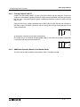
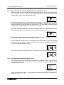
RadioClock - DCF77 Decoding
The RadioClock function enables the reception of time information broadcasted by radio signal
on 77.5 kHz from Frankfurt Germany. Special hardware is required for this feature. Refer to the
α 2 Hardware Manual for more information. After configuring the hardware, follow the
steps below to set the controller for DCF77 decoding:
1 ) From the TopMenu, scroll to “ClockSet” and press the “OK” key.
2 ) From the options that appear, scroll to “RadioClock” and press the “OK” key.
3 ) Only one option appears if RadioClock has not been activated. Scroll to “RadioClock”
and press the “OK” key.
4 ) From the options that appear, scroll to “DCF77” and press the “OK” key. At this point, if the
controller cannot detect a signal the message “No Signal!” will flash on the headline.
5 ) To select the correct analog input that carries the DCF77 time signal, scroll to “Input No.”
and press the “OK” key. Initially “Input No.” will not be visible, it only appears as an option
after the RadioClock function has been enabled.
6 ) Select the Analog Input number from I01 to I08 with the +,- keys and the “OK” key.
7 ) If necessary, adjust for the timezone difference between Frankfurt, Germany and the place
of installation. This amount is added to (subtracted from) the received time. To do this,
scroll to “TimeDiffer” and press the “OK” key.
8 ) Select the timezone difference in half hour increments using the +,- keys. Press “OK” to
enter the timezone difference.
9 ) It is possible to manually start and stop the decoding of the time information. Scroll to
“Manual” and press the “OK” key. Either “Start Act.” or “Stop Act.” will be displayed
depending on the state of the controller at the time.
Note:
The “Input No.”, “TimeDiffer” and “Manual” selections will only be displayed when
“DCF77” has been enabled from the “RadioClock” menu.
The error message “No Signal!” will flash on the headline if the controller does not receive the
DCF77 signal when the input is setup for the RadioClock function. If there should be a signal in
the installation area, check the setup and hardware for faults.
When in STOP mode and “Start Act.” is used to manually start DCF77 decoding, the user must
check the state of M10 (decoding active flag) 30 minutes after starting the decoding. If M10 is
off, DCF77 decoding finished without error. If M10 is still ON, there is a problem with either the
wiring or the availability of the signal in the location of use (e.g. antenna problems). The user
should check both possible causes.
3 - 17
α2 Simple Application Controllers
3.6.5
System Menu 3
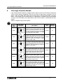
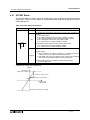
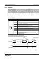
SummerTime
The Summertime menu will display six choices when entered.
Cancel - Turns off the Summertime clock setting.
Manual On - Moves the clock one hour ahead immediately and will remain ON until cancelled.
Date Type - Set the On date, Off date, and Time adjustment.
UK Type - Last Sunday of March to the last Sunday of October.
US Type - First Sunday of April to the last Sunday of October.
EU Type - Last Sunday of March to the last Sunday of October.
Free Type - Set the On/Off date among each Sundays, Hour of time change, and Adjust time.
The time changes for the UK timezone take place at 1:00 AM in the Spring and 2:00 AM in the
Autumn. Time changes in the US and EU setting take place at 2:00 AM in the Spring and 3:00
AM in the Autumn.
If the controller time has been adjusted for Summertime, an “s” will precede the hour number
on the display screen.
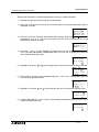
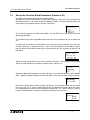
Setting the controller for Summertime operation:
1 ) From the TopMenu, scroll to “Others...” and press the “OK” key.
2 ) From the options that appear, scroll to “Summertime” and press the “OK” key.
3 ) Scroll to the desired setting (see above for information on settings).
4 ) Press the “OK” key to accept the setting.
5 ) If the display time has been adjusted, an “s” will precede the hour number on the display
screen. If the date is outside of the “summertime” range, no visible sign will appear.
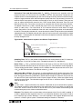
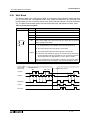
Figure 3.14: Changeover Date and Time
Changeover Date and Time (a.m.) for 2002
Modes
3.31.02
US
EU
UK
2:00 3:00
1:00 2:00
4.7.02
10.27.02
2:00 3:00
S U M M E R
T
I
M E
add 1 hour
Mode
Free
3:00 2:00
3:00 2:00
2:00 1:00
subtract 1 hour
On date
Off date
S U M M E R
Month (1-12)
Sunday (1st, 2nd, 3rd, 4th, 5th)
T
I
M E
Month (1-12)
Sunday (1st, 2nd, 3rd, 4th, 5th)
Hour of time change (00:00am, 01:00am, 02:00am, 03:00am)
Adjust time (0-180 minutes)
Note:
When Summertime is in effect, the clock should not be set to the changeover time. For
example, the clock should not be set to 2:00 a.m. on March 7, 2002 when US Summertime is
enabled. There will be an error in the displayed time.
3 - 18
α2 Simple Application Controllers
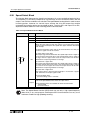
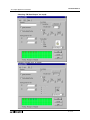
3.6.6
System Menu 3
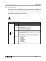
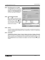
DispPass
DispPass provides the α2 Series Controller with three distinct security levels, limiting the users’
ability to make changes to program parameters (i.e. the SetPeriod parameter of the
SpeedDetect FB). A non-authorized user will be able to navigate the display screen from field
to field, but will not be able to make changes without, first, entering the appropriate password.
There are three passwords that can be set from the front panel or the VLS software. Each
password can control access to many different displayed parameters.
The security level for a displayed parameter must be assigned with the VLS software but, the
actual password can be set, changed or removed with the front panel keys. The following is the
step-by-step process for modifying password settings.
To set the Level 1, Level 2 or Level 3 Password:
1 ) From the TopMenu, scroll to “Others...” and press the “OK” key.
2 ) From the options that appear, scroll to “DispPass” and press the “OK” key.
3 ) Select “Level 1”, “Level 2” or “Level 3”
4 ) Enter the Password with the +, - and directional buttons.
5 ) Press OK to activate the password.
To remove the Level 1, Level 2 or Level 3 passwords:
1 ) From the TopMenu, scroll to “Others...” and press the “OK” key.
2 ) From the options that appear, scroll to “DispPass” and press the “OK” key.
3 ) Select a security level with a key icon by it.
4 ) Enter the appropriate level Password with the +, - and directional buttons.
5 ) Press OK to deactivate the password.
To change a password:
To change a password perform the “To remove the Level 1, Level2 or Level 3 Passwords”
procedure then the “To set the Level 1, Level 2 or Level 3 Passwords” procedure from above.
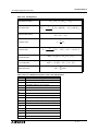
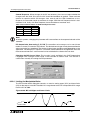
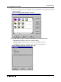
The example window below shows how to assign a password to a function block parameter
being displayed on the front panel. In this example, the SpeedDetect function block has been
used.
1 ) Select the parameter that will be displayed, in this example, SetPeriod.
2 ) Select the security level.
3 ) Assign the password in the Password Dialog Box.
3 - 19
α2 Simple Application Controllers
3.6.7
System Menu 3
Password
The password consists of four digits and will prohibit entry into the ProgEdit, Monitor, Disp
Pass and Serial Com modes only. All other menu options can be accessed when a Password
is used.
To Enter a Password:
1 ) Select “Others...” Menu Option.
2 ) Select “Password” from the “Others...” Menu Options
3 ) Use the “+” and “-” keys to enter the desired password.
4 ) Press the “OK” key to accept and activate the password.
5 ) A key symbol will now be displayed at the top of the α2 display.
To Cancel a Password:
1 ) Select the “Others...” Menu Option.
2 ) Select “Password” from the “Other” Menu Options. “Cancel Password” should appear on
the top of the screen.
3 ) Use the “+” and “-” keys to enter the current password.
4 ) Press the “OK” key to accept and deactivate the password.
5 ) The key symbol will be removed from the α2 display.
Note 1: A Password protected program in an AL2-EEPROM-2 Cassette can be run from and
be downloaded into the main body of the controller.
Note 2: A controller containing a Password protected program can accept or transfer
programs to an AL2-EEPROM-2.
Note 3: The Password can also be set/deleted from the AL-PCS/WIN-E software or deleted by
the “PROGCLEAR” command.
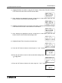
3.6.8
Enhanced User Program Protection (Version 2.20 or later)
Besides the existing user program password protection two new kinds of user program
protection are established.
- Program Read Protection
- Copy Program To Memory Cassette Protection
1) Program Read Protection
The Program Read Protection prohibits any kind of read access to the user program in an α2
(Version 2.20 or later).
This protection can be set only in VLS by downloading a user program with a 5 digit user
program password set, '1' as the first digit.(“1****”:10000 to 19999)
When the protection is set, the program password can't be changed at α 2 by soft key
operation.
The program read protection is reset, when the controller content is erased (VLS or α2) or an
unprotected user program (program read protection not set) is downloaded by VLS.
This protection doesn't work in older α2 (FW version 1.00 and 2.14), but it is also not reset in
those controllers, thus it is inherited in case of copying by VLS or memory cassette to another
α2.
When the program read protection is set, it`s also not possible to upload a user program with
an older version of VLS.
Copying the user program to a memory cassette is also prohibited, when the protection is set.
3 - 20
α2 Simple Application Controllers
System Menu 3
Note:
When the program read protection function is used and the password is forgotten, the program
can't be recovered by any methods. So, please take care to handle the function.
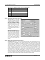
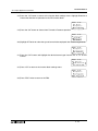
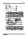
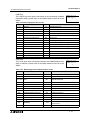
The following table shows the possible and prohibited actions in case the Program Read
Protection is set.
Action
Program Download (VLS to α2)
Program Upload (α2 to VLS)
VLS
-
9
Switch RUN/STOP
9
9
9
9
Controller Contents Clear
Download New/Same User Program
Reset Flag in α2 controller
Read Program Name
Program Erase
Programming by
Keys
α2 Display and Soft
Monitoring
Program Parameter Change
Others
9
Monitoring
Program Parameter Change
α2
Comment
For monitoring the program must be
exists in the PC that runs VLS for monitoring, thus the user program can be seen
anyway.
-
9
9
-
Program can be read out (except display
manager contents) by α2 display.
-
Program can be read out (except display
manager contents) by α2 display.
(9)
As long a for program parameter change
the monitoring display isn't used, the program parameter can be changed.
Copy to memory cassette
-
Dedicated Communication
9
9 : Action is possible , -: Action is not possible
2) Copy Program To Memory Cassette Protection
The Copy Program To Memory Cassette Protection prohibits copying of an α2 user program
from main body memory to a memory cassette.
This flag doesn't work in older α2(FW version 1.00 and 2.14), but it is also not reset in those
controllers, thus it is inherited in case of copying by VLS or memory cassette to another α2.
- Password
0000 to 9999(Four digits)
- Program Read Protection
10000 to 19999(Five digits)
Memory Cassette Protection
3 - 21
α2 Simple Application Controllers
3.6.9
System Menu 3
Serial Com
The modem function capability of the α 2 allows remote monitoring via a PC and program
upload/download. The communication must take place using Visual Logic Software (VLS) and
the communication must be initiated accordingly. (The modem connected to the α 2 is
initialized upon the α2 start-up. Dialing options from a command or specific conditions are not
available).
Command - Enter the AT command for the modem to be connected to the controller.
Reference the Modem User manual for details on that unit’s AT command. Choose the first
letter or symbol by using the ( ) and ( ) arrows. When the symbol is showing in the command
line, use the ( ) and ( ) arrows to move to adjoining spaces. Enter up to 64 letters/symbols
and accept the whole string with the “OK” key when finished inputting the data. (There is no
need to accept each letter with the “OK” key).
Delay - The Delay function sets the length of time the α2 will wait after power on before setting
the setup AT command to the modem. Choose a value of 0 - 10 seconds using the “+” or “-”
keys. The modem connected to the Personal Computer with VLS software must be set ON
prior to the α2 modem turning on.
The GSM function allows a SMS (Short Message Service) message to be sent to either a
mobile telephone or an email account. The short message provides the remote user with the
identical LCD screen’s data. By recieving a short message by α2, SMR FB bit output or word
output can be changed this remote switch commands carried out. Refer to the α 2
Communication Manual for detailed explanation concerning GSM parameters.
The OtherCom function provides the user with an on-line programming feature using
dedicated protocol. Refer to the α 2 Communication Manual for detailed explanation
concerning Dedicated Protocol parameters.
3 - 22
α2 Simple Application Controllers
System Menu 3
3.6.10 Memory cassette
The Memory Cassette EEPROM is the active memory whenever it is properly installed in
the α2 controller. The controller must be powered down before installing/removing the
memory cassette or an error will occur.
To Verify a Program:
1)
2)
3)
4)
5)
6)
7)
Install the AL2-EEPROM-2. Refer to the AL2-EEPROM-2 instruction manual for help.
Select “Others...” in the Top Menu.
Select “ProgTran.”
Select “Verify”.
Choose “OK” to proceed or “ESC” to exit.
If the program is successfully verified, the work “Completed” will blink on screen.
If the programs are not the same, the words “Verify Error” will blink onscreen.
To Transfer a Program from the Cassette to the α2:
1)
2)
3)
4)
5)
6)
Install the AL2-EEPROM-2. Refer to the AL2-EEPROM-2 instruction manual for help.
Select “Others...” in the Top Menu.
Select “ProgTran.”
Select “Cassette→”.
Choose “OK” to proceed or “ESC” to exit.
When the program is successfully transferred, “Completed” will blink on the display.
To Transfer a Program from the α2 to the Cassette:
1)
2)
3)
4)
5)
6)
Install the AL2-EEPROM-2. Refer to the AL2-EEPROM-2 instruction manual.
Select “Others...” in the Top Menu.
Select “ProgTran.”
Select “Cassette←”.
Choose “OK” to proceed or “ESC” to exit.
When the program is successfully transferred, “Completed” will blink on the display.
To apply the “ProtectSW” Feature:
The “ProtectSW” will write protect the program in the memory cassette. The program cannot
be edited nor erased when the feature is ON.
1)
2)
3)
4)
5)
Install the AL2-EEPROM-2 per the instruction manual.
Select “Others...” in the Top Menu.
Select “ProgTran.”
Select “ProtectSW”.
Choose “On” to activate the feature.
To Remove the “ProtectSW” Feature:
1)
2)
3)
4)
5)
Install the AL2-EEPROM-2. Refer to the AL2-EEPROM-2 instruction manual.
Select “Others...” in the Top Menu.
Select “ProgTran.”
Select “ProtectSW”.
Choose “Off” to de-activate the feature.
In case of an α2 version 2.20 controllers in VLS programming software the "Copy to Memory
Cassette protection" can be set. If this option is set, the copy of a program from α2 version
2.20 controller to Memory cassette is prohibited.
3 - 23
α2 Simple Application Controllers
System Menu 3
3.6.11 Analog Inputs
The Analog Inputs can be configured for three different modes: Normal, TC and PT100.
Normal mode is used for ordinary analog signals. TC and PT100 modes should be used with
the AL2-2TC-ADP and AL2-2PT-ADP modules respectively. For more information on these
modules, refer to the α 2 Hardware Manuals and the individual installation manuals. The
following changes should be made in the Stop mode. Only the “OffsetFine” adjust works in
both RUN and STOP modes.
To Set/Change the modes of the Analog Inputs (Stop Mode only):
1)
2)
3)
4)
Select “Others...” from the TopMenu while in Stop Mode.
Select “Analog In.”
Choose the appropriate input and press OK.
“Mode” will be the only option displayed if the analog input was previously set on “Normal.”
Select “Mode” by pressing the OK button. Then, select the appropriate mode setting.
“Calibrate” and “OffsetFine” should appear on the Analog Input settings menu.
Offset Calibration of the PT 100 and TC inputs (Stop Mode only):
1 ) Before beginning, follow the instructions on preparing the hardware for calibration in the α2
Hardware Manual, Chapter 12 for the PT100 input and Chapter 13 for the TC input.
2 ) Select “Others...” from the TopMenu while in Stop Mode.
3 ) After setting the mode to TC or PT100 (See the method for changing modes in the previous description.), select “Calibrate” from the Analog input settings menu.
4 ) Select -50°C and press OK. This completes the offset calibration procedure.
Gain Calibration of the PT100 and TC inputs (Stop Mode only):
1 ) Before beginning, follow the instructions on preparing the hardware for gain calibration in
the α2 Hardware Manual, Chapter 12 for the PT100 input and Chapter 13 for the TC input.
2 ) Select “Others...” from the TopMenu while in Stop Mode.
3 ) After setting the mode to TC or PT100 (See the method for changing modes in the previous description.), select “Calibrate” from the Analog input settings menu.
4 ) Select 200°C for the PT100 input or 450°C for the TC input and press OK. This completes
the gain calibration procedure.
Fine Adjust for the Offset:
1 ) Select “Others...” from the TopMenu either in Stop or Run Mode.
2 ) After setting the mode to TC or PT100, select “OffsetFine” from the Analog input settings
menu.
3 ) “OffsetFine” can be adjusted while in Run or Stop Mode. Use the + and - buttons to select
the appropriate offset value.
Note:
The fine adjust step size for the PT100 mode is 0.5°C and 1.0°C for the TC mode. The
Fahrenheit step sizes are 0.9°F and 1.8°F respectively.
3 - 24
α2 Simple Application Controllers
System Menu 3
To change the temperature scale setting (Stop Mode only):
1)
2)
3)
4)
Select “Others...” from the TopMenu while in Stop Mode.
Select “Analog In.”
Select “TempScale.”
Select “Celsius” or “Fahrenheit.”
Note:
In Run Mode, the temperature scale can be checked but cannot be changed.
Note:
System flags, M17 through M24, correspond to the 8 possible temperature input channels, I01
through I08. When the analog input is configured for TC or PT100 input, these system flags will
detect a defect in the ADP module’s operation. An input voltage of more than 11 volts will set
the corresponding flag and indicates a sensor problem. An input voltage of 0 volts will also set
the corresponding flag, but indicates a power failure at the ADP module.
3.7
LCD Displays
There are a number of types of data and/or information that can be displayed on the LCD
display besides the menus listed previously.
3.7.1
Image Table
The first LCD display to appear is the Input/Output image table and the Real Time Clock. The
clock shows the current time as set by the user. The Summertime mode is shown by an “s”
preceding the time if activated.
3.7.2
LCD Function
Display up to 12 different letters or characters on each of four lines. Options include character
strings (design your own message), function block data, or analog data.
3 - 25
α2 Simple Application Controllers
3.8
System Menu 3
Block Items
Each block item contains an individual diagram that shows the block number, available number
of input pins, the output pin if applicable, and the block mnemonic. Connections between
blocks can be viewed at the pin locations when connected blocks are shown individually on the
LCD.
3.8.1
Input Blocks
The Input Blocks consist of System Inputs (I01 - I15), Key Inputs (K01-K08), System Bits (M01M24) or Link Inputs (E01 - E04). The input number is shown in the top right hand corner, the
type of input in the lower right hand corner, and the output pin is shown on the far right of the
block. Input Blocks provide information to the Function Blocks or Outputs.
3.8.2
Function Blocks
The individual Function Blocks are described in detail in Chapters 5 and 6. Function Blocks
can have 0 to 4 input pins shown on the left of the diagram and an output shown on the far
right. Some function blocks have data that can be used for comparison purposes only or are
used to display data onscreen. These blocks have no output pins. The number and block
mnemonic are shown in the top right and bottom right locations respectively.
3.8.3
Output Blocks
Output Blocks have one input and one output pin. They only have the capacity for one input
signal through the input pin. The Output Block number and Mnemonic are shown in the top
right and lower right hand corner of the diagram respectively.
3.8.4
Connected Blocks
Blocks that are connected can be shown simultaneously onscreen. The block providing the
output signal will be shown on the left of the screen. The input pin accepting the signal will
flash. Any input pin that is already connected will be shown as a solid triangle.
3 - 26
α2
Simple Application Controllers
4.
Direct Programming 4
Direct Programming
The α 2 can be programmed using the front panel keys on the α 2 series controller. The
following sections will describe how to connect/disconnect function blocks, set program
parameters, add Function Blocks, and move around within the program.
The ProgEdit mode in the Stop Menu has full programming capability. The Monitor mode in the
Run Menu has the capability to manipulate Function Block values and settings but cannot edit,
change, or delete the existing program.
4.1
Block Availability
The number of System Inputs and Outputs is determined by the type of controller being
programmed. Configurations include 6 In/4 Out, 8 In/6 Out and 15 In/9 Out. Up to 200
Function Blocks can be used in a program or 5000 bytes of memory. The Function Blocks must
be added in the course of programming. The 8 Keys and the 24 system M bits are
automatically available for every program.
Inputs, Outputs, System Memory Bits, Extended Inputs, Extended Outputs, AS-i Outputs,
Control Bits, and Keys do not count in the Function Block total.
4.2
Connecting Blocks
Any block that has an output pin can be connected to any block that has an (unused) input pin.
System Inputs, Keys, and Memory M bits have output pins only.
Function Blocks and Outputs both contain input and output pins (the Display and TimeSwitch
Blocks are exceptions). Blocks can be connected beginning with an output pin, from “left to
right” on the display, or beginning with an input pin, from “right to left” on the display.
4.2.1
To connect the blocks from the left (signal provider) block to right (signal
receiver) block.
It is necessary to choose the block to provide the output (step 1), the block to accept the signal
(step 2), and the pin with which to accept the signal (step 3).
1 ) Step 1: Select the block providing the data to be output and move to the right until the
output pin is flashing. Press the “+” button to “add” a block.
01
In
2 ) Step 2: Choices will appear on the right side of the screen that include System Outputs (if
available), existing Function Blocks that have free input pins, and the option to add a new
function block (AddFB, see section 4.4). Scroll to the preferred option and select using the
“OK” key.
01
Ad d FB
O0 1
Co n n e c t
4-1
α2 Simple Application Controllers
Direct Programming 4
3 ) Step 3: The block accepting the signal will display as many of its input pins as possible (at
times they will not all fit on-screen). Pins that have been used will show as filled triangles;
pins that are open will show as “>” signs. A “Connect” prompt will appear on-screen, either
above or below the left hand block. The current input choice will flash. Scroll to the desired
pin and press the “OK” key to accept. The process is complete.
01
001
P
Co n n e c t
4.2.2
To connect the blocks from the right (signal receiver) block to left (signal
provider) block.
It is necessary to choose the block input pin (Step 1), the signal provider (Step 2), and to
accept the connection (Step 3).
1 ) Step 1: Select the block that will be receiving the signal and move left until an input pin is
flashing. Scroll to the desired unused input pin (“>”). Press the “+” key to begin the
connection process.
01
001
P
In
CN
2 ) Step 2: Because output pins may have multiple connections, all the Keys, Function Blocks,
System Inputs, Outputs will show on the left of the screen as well as an option to “AddFB”.
Scroll to the preferred option and Press the “OK” key.
Co n n e c t
P
Ad dFB
M0 1
CN
3 ) Step 3: The chosen connection will be flashing on-screen along with the “Connect” prompt.
Press the “OK” key to accept.
Co n n e c t
P
CN
In
4.3
Disconnect Two Blocks
Blocks can be disconnected by implementing the following procedure.
Move to the connection that is to be disconnected. Enter “-” as the disconnect command. A
“Disconnect” prompt will appear on-screen. Press the “OK” key to accept the disconnect.
4-2
α2
Simple Application Controllers
4.4
Direct Programming 4
Methods to Create a Function Block
The two methods of creating a Function Block. The New FB option in the Edit Menu and
AddFB option when connecting two blocks.
4.4.1
New FB
To use the New FB option, proceed to the Edit Menu (Chapter 3) using the “ESC” key. Scroll to
the New FB option and press the “OK” key. Scroll to the desired Function Block and press the
“OK” key to create a New FB. The block will appear on the Function Block Diagram board.
FB Se l e c t
A ND
OR
Bo o l e a n
Se t / Re s e t
R e t e n t SR
De l a y e dAL
4.4.2
AddFB
When connecting a Function Block, scroll to the AddFB prompt and press the “OK” key. This
invokes the Function Block list. Scroll to the desired Function Block and choose by pressing
the “OK” key. The Function Block will be shown on the screen with the connecting block.
4.5
Function Block Editing
To enter the Function Block editing menu (Chapter 3), press the “OK” key when the Function
Block number and name are flashing on the screen. Up to three options appear on-screen:
Setup FB, Change No, and Delete FB. The Setup Function option is not valid for some
Function blocks and so will not always appear and certain function blocks will also contain a
Time unit option (refer to chapter 6 for function block specification).
4.5.1
Setup Function Block
Each Function Block has its own individual parameters outlined in Chapter 6. The Function
Blocks might have multiple data screens that can be altered. As with other menu options, the
“ESC” key will move the screen back to a higher menu option without changing the option
parameters for that screen. If there are multiple data screens in an option, enter the required
data and accept each screen using the “OK” key. Use the “ESC” key to exit the Function Block.
4.5.2
Change No. (of a Function Block)
Change the number of an existing Function Block with this screen. The current FB number is
shown on-screen when the option is selected. Scroll up or down with the “+” or “-” keys to find
an open FB number. Press the “OK” key to accept the new number.
4.5.3
Delete FB
This menu option will Delete the current Function Block. After the Delete FB is chosen, confirm
the delete operation with “OK” or use the “ESC” key to cancel the function. All connections to
the Function Block will be removed with the block.
4-3
α2 Simple Application Controllers
4.6
Direct Programming 4
Movement between Function Blocks
There are a number of ways to move from one item to another when in the ProgEdit or Monitor
modes.
4.6.1
Movement Between Unconnected Blocks
Movement between System Inputs, System Outputs, Keys, and M bits can be accomplished
with the “+” and “-” keys. When the block number is flashing on-screen, press the “+” key to
scroll to the higher value of the same block type; e.g. move from I01 to I02 to I03...until the
highest value is reached. The scroll will then proceed to the lowest value of the next block type.
The same technique will work for the “-” key in the opposite direction.
Function Blocks can be scrolled through in the same manner, although only the Function
Blocks are rotated through in this case.
4.6.2
Movement Between Connected Blocks
The Right arrow moves horizontally (to the right) along the path of connections between
blocks. If an output pin is connected to multiple input pins, the current path will flash. The Up
and Down arrows can be used to choose the desired path. The left arrow will move back along
the path of the connections to the left.
4.6.3
The Jump Command
The “ESC” key can be used to enter the Edit Menu at anytime when a function block is
displayed on the LCD screen. (The “ESC” key will cancel in-process commands first. Keep
pressing the “ESC” key until the Edit Menu is displayed). Select the Jump Command. Choose
any system Memory Bit, Input, Output, Key, AS-i Input, AS-i Output, Extended Input, Extended
Output, or existing Function Block by using the front panel keys. Press “OK” to “Jump” to the
chosen block in the programming mode.
E d i t Me n u
P r o gS i z e
J u mp
New FB
Ex i t
Mn e mo n i c
4.7
Using Keys as Inputs
Connect the Keys for use as Manual Inputs by using the Jump command to access the desired
key, by connecting a Function Block or Output as described in Chapter 3, or by scrolling
through the blocks as described in section 4.6.1.
The programmed Key(s) will give an output signal for as long as the key is depressed.
4-4
α2
Direct Programming 4
Simple Application Controllers
4.8
The Monitor Mode
Function Block values and Output status can be manipulated from the Monitor option.
When placed in the Run mode, the α2 defaults back to the I/O status screen. Press the “ESC
and OK” keys together to enter the Top Menu and then enter Monitor. The program will now be
displayed on-screen. Movement among the function blocks is the same as in the ProgEdit
mode.
4.8.1
Monitor/Update Function Block Values
Move to the function block to monitor and enter Setup FB. The Function Block Values can be
updated and monitored. Changes to current values will be valid only while in the Monitor Mode.
Changes to Set point data and the comparison values will be written to the system memory.
Type
Input
Output
Abbreviated Terms
Forcing Conditions
I
1
EI
1
E
2
O
2
E0
2
A
2
Key
K
3
System bit
M
3
Control bit
N
2
Function Block
B
3
1 ) It is possible to force ON/OFF, however, the status is decided by hardware control.
2 ) It is possible to force ON/OFF, however, the status is decided by programming control.
3 ) It is possible to force ON/OFF. Only some FB, however, the status is decided by programming control.
4-5
α2 Simple Application Controllers
4.8.2
Direct Programming 4
Forcing Outputs ON/OFF
Outputs can be forced ON/OFF if there is no direct conflict with the program. To force an
Output On, proceed to the position where the Output name and number are flashing and press
the “OK” key. A solid rectangle will appear underneath the block number to signify that the
block is ON.
Input pins will have a smaller solid block next to their arrow to show that they are activated. In
the block at right, the Delay output pins are ON, along with the input and output pins for the
system Output O01.
01
\
001
Ou t
An example of a block that cannot be forced follows.
Ex. Output O01 is connected to System Bit M01. M01 is constantly ON, therefore Output O01
is constantly ON and cannot be forced OFF.
01
\
O0 2
?
_M
4.8.3
Add/Delete Function Blocks in the Monitor Mode
The user cannot Add or Delete Function Blocks while in the Monitor mode.
4-6
α2
5.
The Logic Function Blocks 5
Simple Application Controllers
The Logic Function Blocks
Logic Function Blocks operate by reading whether signals are ON or OFF and then setting the
status of their Outputs accordingly. There are six types of logic blocks available in the α2
Series - AND, OR, NAND, NOT, NOR, XOR. Analog signals cannot be processed by the Logic
blocks. In this chapter, each Function Block has a description, a diagram of the Function Block
as seen on the LCD Display, and a logic table to show how the Output is controlled by the input
signals.
Table 5.1: Boolean Logic function blocks
Logic
Block
State
Logic Block
Displayed
AND
1
2
3
4
OR
1
2
3
4
00
O
AND
00
O
OR
00
NOT
O
1
NT
00
XOR
O
1
2
XOR
NAND
NOR
1
2
3
4
1
2
3
4
00
O
NAND
00
O
NOR
Description
Memory
Use
Section
Reference
T h i s f u n c t i o n exe c u t e s l o g i c a l A N D
operation on given input signals. The input
signals connected should be of bit input
type only. 4 Bit input pins and 1 Bit output
pin. If all the inputs are ON then the output
is ON, otherwise output is OFF.
19 Byte
5.1
This function executes logical OR operation
on given input signals. The input signals
connected should be of bit input type only. 4
Bit input pins and 1 Bit output pin. If all the
i n p u t s a r e O F F t h e n o u t p u t i s O F F,
otherwise output is ON.
19 Byte
5.2
This function executes logical NOT operation on given input signal. The input signal
connected should be of bit input type only. 1
Bit input pin and 1 Bit output pin. Output is
negation of Input given.
10 Byte
5.3
This function executes logical XOR operation on given input signals. The input signals connected should be of bit input type
only. 2 Bit input pins and 1 Bit output pin.If
both the inputs are either OFF or ON then
out put is OFF, otherwise output is ON
13 Byte
5.4
This function executes logical NAND
operation on given input signals. The input
signals connected should be of bit input
type only. 4 Bit input pins and 1 Bit output
pin. If all the inputs are ON then output is
OFF, otherwise output is ON
19 Byte
5.5
This function executes logical NOR
operation on given input signals. The input signals connected should be of bit input type
only. 4 Bit input pins and 1 Bit output pin. If
all the inputs are OFF then out put is ON,
otherwise output is OFF
19 Byte
5.6
The logic FB have no parameters.
5-1
α2 Simple Application Controllers
5.1
The Logic Function Blocks 5
The AND Block
The AND block comes ON when all the inputs are ON.
Any Input that is OFF will keep the Output turned OFF.
Unused inputs are considered to be ON.
If no Input pins are connected, the block output is OFF.
01
1
Output
2
1
2
3
4
00
O
AND
3
AND
4
Table 5.2: AND Logic gate
Input 1
Input 2
Input 3
Input 4
Output
On
On
On
On
On
On
On
On
Off
Off
On
On
Off
On
Off
On
Off
On
On
Off
Off
On
On
On
Off
On
On
Off
Off
Off
On
Off
Off
On
Off
Off
Off
On
On
Off
Off
On
On
Off
Off
On
Off
On
Off
Off
Off
On
Off
On
Off
On
Off
Off
Off
Off
Off
On
Off
Off
Off
Off
Off
On
Off
Off
Off
Off
Off
On
Off
Off
Off
Off
Off
Off
5-2
α2
Simple Application Controllers
5.2
The OR Block
The Logic Function Blocks 5
The Output comes ON when any input is ON.
The Output remains OFF only if all the inputs are OFF.
Unused Inputs are considered to be OFF
1
01
Output
2
1
2
3
4
00
O
OR
3
4
OR
Table 5.3: OR Logic gate
Input 1
Input 2
Input 3
Input 4
Output
On
On
On
On
On
On
On
On
Off
On
On
On
Off
On
On
On
Off
On
On
On
Off
On
On
On
On
On
On
Off
Off
On
On
Off
On
Off
On
On
Off
Off
On
On
Off
On
On
Off
On
Off
On
Off
On
On
Off
Off
On
On
On
On
Off
Off
Off
On
Off
On
Off
Off
On
Off
Off
On
Off
On
Off
Off
Off
On
On
Off
Off
Off
Off
Off
5-3
α2 Simple Application Controllers
5.3
The Logic Function Blocks 5
The NOT Block
The NOT block takes a signal and inverts it - an Input that is ON
has an Output that is OFF, and vice versa.
The Output comes ON when the input is OFF.
The Output is OFF when the input is ON.
If no Input pin is used, the block output is OFF.
The electrical circuit for a NOT block is the same as a Normally
Closed input.
Table 5.4: NOT Logic gate
5.4
Input
Output
On
Off
Off
On
00
O
1
NT
The XOR Block (Exclusive OR)
The Output comes ON when one input is ON and one is OFF. The
Output remains OFF when both Inputs are equivalent (either both
ON or both OFF).
Unused Inputs are considered to be OFF.
Table 5.5: XOR Logic gate
Input 1
Input 2
Output
On
On
Off
On
Off
On
Off
On
On
Off
Off
Off
00
O
1
2
XOR
5-4
α2
5.5
The Logic Function Blocks 5
Simple Application Controllers
The NAND Block (Not AND)
The Output comes ON if any or all inputs are OFF.
If every input is ON, the Output turns OFF.
Unused Inputs are considered to be ON.
If no Input pin is used, the block output is OFF.
(This is equivalent to an AND block followed by a NOT block)
1
1
2
3
4
00
O
NAND
01
Output
2
3
4
NAND
.
Table 5.6: NAND Logic gate
Input 1
Input 2
Input 3
Input 4
Output
On
On
On
On
Off
Off
Off
Off
Off
On
On
On
On
Off
On
On
On
Off
On
On
On
Off
On
On
On
Off
On
On
On
On
On
On
Off
Off
On
On
Off
On
Off
On
On
Off
Off
On
On
Off
On
On
Off
On
Off
On
Off
On
On
Off
Off
On
On
On
On
Off
Off
Off
On
Off
On
Off
Off
On
Off
Off
On
Off
On
Off
Off
Off
On
On
5-5
α2 Simple Application Controllers
5.6
The Logic Function Blocks 5
The NOR Block (Not OR)
The Output comes ON when all the inputs are OFF.
The Output remains OFF if any input is ON.
If no Input pin is used, the block output is OFF.
Unused Inputs are considered to be OFF
This block is equivalent to an OR block followed by a NOT block
1
2
3
4
00
O
NOR
01
1
Output
2
3
NOR
4
Table: 5.7: NOR Logic gate
Input 1
Input 2
Input 3
Input 4
Output
Off
Off
Off
Off
On
On
On
On
On
Off
On
On
On
Off
Off
On
On
Off
On
Off
On
Off
On
On
Off
Off
On
On
On
Off
On
On
Off
Off
Off
On
Off
On
Off
Off
On
Off
Off
On
Off
Off
On
On
Off
Off
Off
On
Off
On
Off
Off
Off
On
On
Off
On
Off
Off
Off
Off
Off
On
Off
Off
Off
Off
Off
On
Off
Off
Off
Off
Off
On
Off
5-6
α2 Simple Application Controllers
6.
Function Blocks 6
Function Blocks
The α2 series controller is fundamentally based on function block programming. The blocks
provide a wide range of possible operations and have been preprogrammed for ease of use.
Some Function Blocks have parameters that can be tailored to meet individual requirements in
the programs. Each function block will have a description of the Block’s purpose, a diagram of
how the Block will appear on-screen, and a description of the inputs, outputs, and available
options.
Table 6.1.1: Function Block List
FB Name
FB Symbol
1
2
3
4
Boolean
[BL]
Set/Reset
[SR]
S
R
Pulse
[PL]
I
000
P
O
BL
000
P
O
SR
000
P
O
PL
000
Alternate
[AL]
I
C
Delay
[DL]
I
C
One Shot
[OS]
Flicker
[FL]
O
AL
000
P
O
DL
I
C
000
P
O
OS
I
000
P
O
FL
Description of Function Block
Memory
Use
Section
The Boolean Function Block uses Boolean
algebra to control the ON/OFF state of an
output. An operational expression consists
of either the AND, OR, XOR or NOT form.
*1
6.3
The Set/Reset Function Block either holds
an output ON (set) or releases the output
OFF (reset.) Priority can be given to either
input pin if both inputs have been energised
simultaneously. The default priority setting
is dedicated to the reset input pin.
14 Byte
6.4
The Pulse Function Block sends a single
pulse to the output pin if the input pin
receives either an “ON to OFF”, “OFF to
ON” or “ON to OFF And OFF to ON” input
operation.
10 Byte
6.5
The Alternate Function Block is used to
reverse the ON and OFF state of the output
as and when the input pin receives a signal.
The output will be set ON when the input
pin goes high and remain ON until the input
receives the second rising edge.
13 Byte
6.6
The Delay Function Block provides an ON
delay timer and an OFF delay timer. Time
intervals for either situation can be set. The
time unit can be set to 10ms, 100ms or 1s
increments.
19 Byte
6.7
The One Shot Function Block awaits a
signal supplied to the input pin thereafter
setting the output according to the specified
time. The timing parameters control the
state of the output (depending on the
priority setting). The time unit can be set to
10ms, 100ms or 1s increments.
17 Byte
6.8
The Flicker Function Block changes the ON
and OFF state of the output according to a
preset flicker time. The time unit can be set
to 10ms, 100ms or 1s increments.
19 Byte
6.9
6-1
α2
Function Blocks 6
Simple Application Controllers
FB Name
FB Symbol
000
P
O
Time
Switch
[TS]
TS
000
P
Time
Switch m
[TSm]
T Sm
000
P
O
Counter
[CN]
I
C
U/D
Counter
[UD]
U
D
C
P
UD
Compare
[CP]
I
000
P
O
Analog
Output
M
E
Offset
Gain
[OG]
I
Display
[DP]
Zone
Compare
[ZC]
CN
000
P
O
CP
000
P
AO
000
P
OG
I
000
P
DP
I
000
P
O
ZC
Description of Function Block
Memory
Use
Section
The Time Switch Function Block uses a
predefined time schedule to control the ON
and OFF status of the output.
*2
6.10
The Time Switch maintenance Function
Block uses a predefined time schedule to
control the ON and OFF status of the
output. The function block can be setup
from the TopMenu "Parameter" via the front
panel keys.
*2
6.10
The Counter Function Block increments the
current value by one as and when the input
pin receives a signal. When the current
value reaches the set value the output is set
ON. The counter current value is reset as
and when the clear pin receives an input.
16 Byte
6.11
The Up/Down Function block positively or
negatively increments the counter until a
set value is reached thereby setting the
output ON. A preset signal can also equal
the set value regardless of the current value
for the function block and thereby setting
the output ON.
22 Byte
6.12
The Compare Function Block monitors the
current value of the input pin in relation to a
preset expression. The expression consists
of =,>,>=,<,<= or <>. If the compared value
satisfies the expression subsequently the
output pin is set on.
17 Byte
6.13
The Analog Output function takes a digital
value input and delivers a corresponding
analog voltage or current to a selected
channel on the AL2-2DA module.
17 Byte
6.14
The Offset Gain Function Block is based
upon a linear function Y=A/B∗X+C to which
the value obtained from an analog input
(X:A01-A08) is set.
22Byte
6.15
The Display Function Block is used as an
interface between the user and the devices
held within the controller. Current values,
timer messages, user-defined messages
can be read.
*4
6.16
The Zone Compare Function Block
identifies whether the input value lies within
a specified upper and lower limited zonal
area and if so changes the status of the
output accordingly.
20 Byte
6.17
6-2
α2 Simple Application Controllers
FB Name
Schmitt
Trigger
[ST]
Hour
Meter
[HM]
Speed
Detect
[SPD]
PWM
[PWM]
PID
Function Blocks 6
FB Symbol
I
000
P
O
ST
I
C
000
P
O
HM
I
U
C
000
O
P
SPD
I
000
P
O
PWM
A
E
E
A
C
00 00 00
OO
PP
PP II DD
000
Retentive
Alternate
[RAL]
I
C
Addition
[ADD]
I
Subtraction
[SUB]
I
O
RA L
000
O
P
A DD
000
P
O
SUB
Description of Function Block
Memory
Use
Section
T h e S c h m i t t Tr i g g e r F u n c t i o n B l o ck
compares an input value to preset high and
low limits. The output is ON when the input
value reaches the high limit and then falls
below the lower limit. The function only
processes the data when the function block
is receiving an input signal.
19 Byte
6.18
The Hour Meter Function Block holds the
output status ON for a maximum of 32767
hours, 59 minutes and 59 seconds. If the
input pin is turned OFF the elapsed time
will hold its value until either the clear pin
resets the time or the input pin is turned ON
again.
19 Byte
6.19
The Speed Detect Function Block is used to
count the incoming pulses max. 20Hz (with
an extension module max. of 1kHz) for a
set period of time. The upper and lower
limits can be set from -32768 to +32767
and the Period interval’s set range is 1 to
32767 in 10ms increments.
25 Byte
6.20
The Pulse Width Modulation Function Block
changes the output status according to a
set period of time with a minimum of 100ms
and a maximum of 3276700ms in
increments of 100ms. The percentage duty
for the function controls the amount of
elapsed time before the output status is
changed.
16 Byte
6.21
T he PID Function Block is the α2
implementation of PID, a control method
used to obtain stable control over a system
variable. It is a equipped with an Autotuning function, which automatically adjusts
the Function Block parameters for the
specific application.
52 Byte
6.22
The Alternate Function Block is used to
reverse the ON and OFF state of the output
as and when the input pin receives a signal.
The output will be set ON when the input
pin goes high and remain ON until the input
receives the second rising edge. When the
power is turned OFF the function block will
use the last alternation operation to control
the output.
13 Byte
6.23
T h e A D D F u n c t i o n B l o ck i s u s e d t o
summate two input values
20 Byte
6.24
The SUB Function Block is used to subtract
two input values.
20 Byte
6.25
6-3
α2
Function Blocks 6
Simple Application Controllers
FB Name
FB Symbol
Multiplication
[MUL]
I
Division
[DIV]
I
Calculation
[CAL]
I
Shift
[SFT]
SMS
[SMS]
Short
Message
Receiving
[SMR]
MU L
000
O
P
DIV
000
O
P
CA L
I
T
S
R
SFT
I
000
O
P
000
O
S MS
E
R
000
P
O
SMR
Short
Message
Receiving m
[SMRm]
E
R
Call
Detect
[CD]
E
R
Call
Detect m
[CDm]
000
P
O
000
P
O
SMRm
000
P
O
CD
E
R
000
P
O
CDm
Description of Function Block
Memory
Use
Section
The MUL Function Block is used to multiply
two input values.
20 Byte
6.26
The DIV Function Block is used to divide
two input values.
20 Byte
6.27
The CAL Function Block is used to perform
a calculation from the combination of
different Arithmetic function blocks.
*3
6.28
This Shift Function Block is used to transfer
the Shift Input status just before the Input
signal is set ON. It has a bit input pin, a shift
input pin, a set input pin, a reset input pin
and a bit output pin.
19 Byte
6.29
The GSM SMS Function Block sends the
LCD screen as a SMS message to either a
mobile phone handset or an E-mail account
for remote maintenance purposes.
*6
6.30
The Shor t Message Receive Function
Block searches for the occurrence of a
command in the SM. In case the command
text is exactly included in the SM, outputs
are changed.
*7
6.31
The Short Message Receive maintenance
Function Block searches for the occurrence
of a command in the SM. In case the
command text is exactly included in the SM,
outputs are changed. The function block
c a n b e s e t u p f r o m t h e To p M e n u
"Parameter" via the front panel keys.
*7
6.31
The Call Detect Function Block in case the
numbers of digits of both phone numbers
and the phone numbers itself are equal, the
CD Function Block output is switched on.
30 Byte
6.32
The Call Detect Function Block in case the
numbers of digits of both phone numbers
and the phone numbers itself are equal, the
CD Function Block output is switched on.
The function block can be setup from the
TopMenu "Parameter" via the front panel
keys.
30 Byte
6.32
6-4
α2 Simple Application Controllers
Function Blocks 6
Description of Function Block
Memory
Use
Section
The Random One Shot Function Block
emits a random length single pulse to the
output.
19 Byte
6.33
The Delayed One Shot Function Block
emits a single pulse after a controlled delay
to the output.
20 Byte
6.34
The Delayed Alternate Function Block
alternates the status of the output with each
pulse after a controlled delay.
16 Byte
6.35
The Set/Reset Function Block either holds
an output ON (set) or releases the output
OFF (reset.) Priority can be given to either
i n p u t p i n i f b o t h i n p u t s h av e b e e n
energised. The default priority setting is
dedicated to the reset input pin. When the
power is turned OFF the function block will
use the last set or reset operation to control
the output.
14 Byte
6.36
Control
Display
[CDP]
The Control Display Function allows the
user to control the LCD image screens. The
function block can only be set in
AL-PCS/WIN-E software for α 2 Series
Controllers. When control bit N04 is ON, it
is possible to control the displayed User
Screen.
*5
6.37
Connect
[ _B ]
The Connect function block is an internal
device used to show the memory used by
input bits, system bits, AS-interface bits,
and the operation keys. No function block
appears on screen or is shown as being
used in the “Memory Configuration Usage”
dialog box. The purpose is only to calculate
the memory that is used by the bits listed
above.
10 Btye
6.38
Control for external devices through relays
and transistors.
10 Btye
-
FB Name
FB Symbol
Random
One Shot
[ROS]
I
C
Delayed
One Shot
[DOS]
I
C
Delayed
Alternate
[DAL]
I
C
Retentive
Set/Reset
[RSR]
000
P
O
RO S
000
P
O
DO S
000
P
O
DA L
S
R
000
P
O
RSR
000
I
O
_B
System
Outputs
6-5
α2
Function Blocks 6
Simple Application Controllers
Note:
*1 Number of bytes used = 19 + 1 x (Characters in equation)
*2 Number of bytes used = 8 + 4 x (Number of time switches)
*3 Number of bytes used = 30 + 1 x (Characters in equation)
*4 Number of bytes used is decided by the displayed item.
Displayed Item
16 + 1 x (Each character displayed)
Characters
Analog, FB value
Number of bytes, α2 Series
Value
17
Graph
23
Time, Date
14
Time Switch
17
*5 Number of bytes used = 32 + 3 x (Number of screen)
*6 Number of bytes used = 12 + 1 x (Characters in E-Mail address)
*7 Number of bytes used = 37 + (Number of characters of setup commands)
6-6
α2 Simple Application Controllers
Function Blocks 6
Table 6.1.2: Handling of FB data in α2
FB Name
EEPROM
Boolean
Setup
Set/Reset
Setup
Pulse
Setup
Alternate
Setup
Delay
Setup
One Shot
Setup
Flicker
Setup
Time Switch
Setup
Time Switch m
Setup
RAM (hold for 20days)
Counter
Setup
Current counter value, Output status
U/D Counter
Setup
Current counter value, Output status
Compare
Setup
Analog Output
Setup
Offset Gain
Setup
Display
Setup
Zone Compare
Setup
Schmitt Trigger
Setup
Hour Meter
Setup
Actual Time*1
Speed Detect
Setup
PWM
Setup
PID
Setup
Retentive Alternate
Setup
Actual time
Output status
Addition
Setup
Subtraction
Setup
Multiplication
Setup
Division
Setup
Calculation
Setup
Shift
Setup
SMS
Setup
Short Message Receive
Setup
Word output value*2, Bit output status*2
Short Message Receive m
Setup
Word output value*2, Bit output status*2
Call Detect
Setup
Output status *2
Call Detect m
Setup
Output status*2
Random One Shot
Setup
Delayed One Shot
Setup
Delayed Alternate
Setup
Retentive Set/Reset
Setup
Control Display
Setup
Output status
Output status
*1. From Version 3.00 or later:
The actual time of Hour Meter FB with FB number 197...200 is kept in EEPROM.
*2. If configured in FB setup.
6-7
α2
6.1
Function Blocks 6
Simple Application Controllers
Definitions
DirectSet - Enter a value using the “+” and “-” keys.
Analog In - An analog input value from a System Input (A01, A02, A03,... A08).
FB Value - A value contained in a Function Block (T, t, N, n, Direct set, etc.)
Word Comparison - a 16 bit output value from a Function Block.
6.2
Abbreviations
Table 6.2: Abbreviated terms used in describing function block
Term
Description
I
Input pin for function block operation
1,2,3,4
Numbered Input pins for boolean logic type function blocks
O
Output pin for function block operation
S
Set pin for the function block
R
Reset pin for the function block
C
Clear pin for the function block
U
Increments a positive count to the Up/Down Counter Function Block
D
Increments a negative count to the Up/Down Counter Function Block
P
Preset signal input pin for the Up/Down Function Block
N
The count value set by the user, range: 0 - 32767
n
The actual count value. This value c an be set to a one time offset value,
range: 0 - 32767
T
For Shift function block only. Shift input pin
T
User specified Set Time Value, range: 0 - 3276.7sec
t
The elapsed time since the function set ON, range: 0 - 32767sec
Note: The following function block information, details specific explanation concerning
front panel programming using the α2 Series Controller. However, it is assumed the
user has read and understood Direct Programming Chapter 4. Thus, is capable of
connecting function blocks together using the dedicated front panel keys. Hence, each
function block provides step by step instructions for direct input having ignored the
initial key presses detailed in Chapter 4.
6-8
α2 Simple Application Controllers
6.3
Function Blocks 6
Boolean block
The function block creates a logical operation using Boolean algebra consisting of AND, OR,
XOR and NOT gates. It is possible to express the Logic functions in the form of an equation.
Refer to Chapter 5 for detailed information concerning Boolean Logic operation.
Table 6.3: Boolean Function Block
Function
1
2
3
4
000
P
O
BL
Set Item
1,2,3,4
FB
Description
Numbered Input pins for boolean operation to control
User-defined logical boolean operation
Output
The output is controlled directly from the result of the boolean
operation involving the numbered input pins 1,2,3,4.
Table 6.4: Boolean expressional data
Item
Display
Description
AND
∗
Intersection
OR
+
Disjunction
XOR
^
XOR
NOT
!
NOT
(
(
Left parenthesis
)
)
Right parenthesis
1
1
Signal connected to Input pin 1
2
2
Signal connected to Input pin 2
3
3
Signal connected to Input pin 3
4
4
Signal connected to Input pin 4
O
O
Output signal
=
=
Equal sign signal
1 ) Boolean Operation
1
2
1
01
Output
2
3
3
O=1 * 2 + 3
BL
AND OR
6-9
α2
Function Blocks 6
Simple Application Controllers
Setup of the Boolean Function Block directly from the α2 Series Controller
1 ) Allocate the input pin to be used for the function block.
2 ) Press the “OK” key with the cursor in the function block. The function block edit screen is
displayed as shown.
B001 : BL
Se t u p FB
Ch a n g e No
De l e t e FB
3 ) Select Setup FB using the “ and ” keys and press the “OK” key. The boolean function
block edit screen is displayed as shown.
B001 : BL
[ O=
4 ) Enter the boolean expression via the “ ,
displayed as shown.
,
and
3
]
keys”. A boolean expression is
B0 0 1 : BL
3
[ O= 1 * 2 + 3 ]
OR
5 ) Press the “OK” key after entering the boolean expression.
6 - 10
α2 Simple Application Controllers
6.4
Function Blocks 6
Set/Reset Block
The function block will set or reset an output according to the input condition. When the SET
input is energised, the Output is ON. When the RESET input is energised, the Output is OFF.
When both inputs are energised simultaneously, the Output will follow the Priority Setting
signal. A latched Output does not depend on the constant signal to retain its status.
Set Priority - When the Set input comes ON, the Output comes ON and remains ON until the
Reset pin receives a signal. Once the Output is ON, the Set input signal can turn OFF without
effecting the Output. If both the Set and Reset pins are ON, the Output is ON.
Reset Priority - The operation is the same as the Set Priority except that when both pins are
ON, the Output is OFF.
Table 6.5: Set/Rest Function Block
Function
S
R
Set Item
000
P
O
Description
S
Set pin for the function block
R
Reset pin for the function block
FB
Allocates priority to either the set or reset function when both pins are
ON
The output of the function block operates in either an ON or OFF
state.
SR
Output
1) Set the output ON until the reset pin is ON.
2) Decides the status of the output depending which input pin has
priority.
1 ) Operation of reset priority
ON
Input pin S
OFF
Input pin R
OFF
ON
Output
ON
OFF
2 ) Operation of set priority
ON
Input pin S
OFF
Input pin R
OFF
ON
Output
ON
OFF
6 - 11
α2
Function Blocks 6
Simple Application Controllers
Setup of the Set/Reset Function Block directly from the α2 Series Controller
1 ) Allocate the set and reset pins for the function block.
2 ) Press the “OK” key with the cursor in the function block. The function block edit screen is
displayed as shown.
B 0 0 1 : SR
Se t u p FB
Ch a n g e No
De l e t e FB
3 ) Select Setup FB using the “ and
screen is displayed as shown.
” keys and press the “OK” key. The Set/Reset priority
B 0 0 1 : SR
Pr i or i t y
Se t
Re s e t
4 ) Select the Set or Reset priority using the “
to the function block edit screen.
and
” keys and press the “OK” key to return
6 - 12
α2 Simple Application Controllers
6.5
Function Blocks 6
Pulse Block
The function block emits a single pulse at any of the following user defined times:
Table 6.6: Pulse Function Block
Function
Set Item
I
Description
Input pin for pulse operation
Sends a single pulse depending on the function block conditional
setup.
FB
I
000
P
O
1) Rise Edge (From Off to On)
2) Fall Edge (From On to Off)
3) Both Edge (From Off to On and On to Off)
PL
The function block sends a single pulse depending on the chosen
pulse operation
Output
1) Rise Edge (From Off to On)
2) Fall Edge (From On to Off)
3) Both Edge (From Off to On and On to Off)
1 ) Rise Edge (From Off to On) Operation
Input pin I
Output
1 operation cycle
(time to process program once)
2 ) Fall Edge (From On to Off) Operation
Input pin I
Output
1 operation cycle
(time to process program once)
3 ) Both Edge (From Off to On and On to Off) Operation
1 pulse width
Input pin I
Output
2 pulse width
1 operation cycle
(time to process program once)
6 - 13
α2
Simple Application Controllers
Function Blocks 6
Setup of the Pulse Function Block directly from the α2 Series Controller
1 ) Allocate the input pin to be used for the function block.
2 ) Press the “OK” key with the cursor in the function block. The function block edit screen is
displayed as shown.
B001 : PL
Se t u p FB
Ch a n g e No
De l e t e FB
3 ) Select Setup FB using the “ and ” keys and press the “OK” key. Select using the “
and ” keys the initiation type for the pulse operation.
B001 : PL
R i s eEdge
Fa l l Edge
Bo t hEdge
4 ) Press the “OK” key to return to the function block edit screen.
6 - 14
α2 Simple Application Controllers
6.6
Function Blocks 6
Alternate Block
The function block inflicts a reversal of the ON and OFF state of the output as and when the
input is given to the input pin.
Table 6.7: Alternate Function Block
Function
Set Item
000
I
C
O
Description
I
Input pin for alternation operation
C
Clear input pin resets the state of the output regardless of the input
given.
FB
N/A
The output is affected in the following operation:
AL
Output
1) Reverse the ON/OFF state of the output whenever the input
signal’s ON/OFF operation to the input pin is turned ON (ON to OFF
or OFF to ON)
2) The clear selection resets the output regardless of the input given.
1 ) Alternate Operation
Input pin I
ON OFF
ON
Input pin C
Output
OFF
ON OFF
6 - 15
α2
6.7
Function Blocks 6
Simple Application Controllers
Delay Block
The function block delays the signal to an output for a set length of time. The On or Off delays
can be set individually or in combination. Example: The On Delay Time is set to 5 seconds.
The Delay Block Input signal comes ON; five seconds later the Delay Block Output will come
ON. The Output signal stays ON as long as the Input signal is ON. The Output signal turns
OFF at the same time the Input signal turns OFF. The Clear Input will turn the Output OFF and
cancel the current operation. The Clear pin over-rides the Input pin if both signals are ON
simultaneously.
The On Delay option will delay the Output from turning ON for a set time after the Input comes
ON. The Off Delay will delay the Output from turning OFF for a set time after the Input has
turned OFF.
Table 6.8: Delay Timer Function Block
Function
Set Item
Description
I
Input pin for delay timer operation
C
Clear input pin resets the state of the output regardless of the input
given.
FB
Time units: 10ms, 100ms or 1s (*Note)
The following items are applicable for the delay function block:
I
C
1) The lag time setting for energising the output from a given input
signal can be given a controlled delay time; The starting value has a
range from 0s to 32767s
000
P
O
2) The lag time setting for denergising the output from a given input
signal can be given a controlled delay time; The starting value has a
range from 0s to 32767s
DL
Output
3) If the clear signal of the input pin C is turned on while the delay
function block is in operation consequentially the current value of the
ON delay timer and OFF delay timer resets to “0.” Thus, the output is
turned OFF.
4) The following items are available for other function blocks:
a) On Delay
b) Current On Delay
c) Off Delay
d) Current Off Delay
Note: The ON/OFF delay time cannot be less than one scan time for the controller;
otherwise, the Delay Function Block will not perform its assigned task for the time
specified. Users can monitor the scan time from the α2 Series Controller. Scan time is
dependent on the user-program; therefore, caution is needed as and when time units
are selected.
1 ) Delayed Operation
In p u t p in I
ON
ON
In p u t p in C
O u tp u t
ON
O n d e la y
Tim e
OFF
O ff d e la y
Tim e
S h o rte r th a n
O n d e la y tim e
O n d e la y
Tim e
O n d e la y
Tim e
S h o rte r th a n
O ff d e la y tim e
6 - 16
α2 Simple Application Controllers
Function Blocks 6
2 ) ON delay timer
Input pin I
ON
ON
Input pin C
Output
ON OFF
On delay
Time
Shorter than
On delay time
On delay
Time
On delay
Time
3 ) OFF delay timer
Input pin I
Input pin C
Output
Off delay time
Shorter than Off delay time
Setup of the Delay Function Block directly from the α2 Series Controller
1 ) Allocate the input pin to be used for the function block.
2 ) Press the “OK” key with the cursor in the function block. The function block edit screen is
displayed as shown.
B0 0 1 : DL
T i me u n i t
Se t u p FB
Ch a n g e No
De l e t e FB
3 ) Press the “OK” key to set the Time unit for the delayed output.
T i me u n i t
1 0 ms
1 0 0 ms
1 s
4 ) Press the “OK” key having selected the value for the delayed time unit and return to the
function block edit screen. Using the “ and ” keys highlight the Setup FB and press the
“OK” key. The screen displayed is shown.
B0 0 1 : DL
OnDe l a y
O f f De l a y
5 ) Select the On or Off Delay using the “ and
time can be entered using the “+” or “-” keys.
” Keys and press the “OK” key. The Delay
B0 0 1 : DL
OnDe l a y
T=
0 . 1s
t=
0 . 0s
6 ) Press the “OK” key to accept the time figures and subsequently press the “ESC” key to
return to the function block edit screen.
6 - 17
α2
6.8
Function Blocks 6
Simple Application Controllers
One Shot Block
The function block gives a single Output pulse for a controlled duration of time. If the Set Time
is 0 seconds, the block will function like the Pulse block. The Reset Input returns the Output to
the OFF condition and will override the Input pin.
Table 6.9: One Shot Function Block
Function
Set Item
Description
I
Input pin for one shot operation
C
Clear input pin resets the state of the output regardless of the input
Time units: 10ms, 100ms or 1s (*Note)
FB
I
C
000
P
O
The One Shot time T and t can be set using the chosen time units.
A Time or Input priority can be set.
The following items are applicable for the one shot function block:
OS
1) A period of 0s to 32767s for a single pulse output can be set.
Output
2) The output is turned ON during the single shot time duration as
and when the input pin receives a signal.
3) The output is cleared as and when the clear pin receives a signal.
4) The following items are available for other function blocks:
a) One Shot
b) Current One Shot
Note: The set time cannot be less than one scan time for the controller; otherwise, the
One Shot Function Block will not perform its assigned task for the time specified.
Users can monitor the scan time from the α 2 Series Controller. Scan time is
dependent on the user-program; therefore, caution is needed as and when time units
are selected.
One Shot Operation
1 ) Time Priority
Input pin I
Input pin C
Output
ON OFF
set time
set time
2 ) Input priority
Input pin I
Input pin C
Output
set time
6 - 18
α2 Simple Application Controllers
Function Blocks 6
Setup of the One Shot Function Block directly from the α2 Series Controller
1 ) Allocate the input pin to be used for the function block.
2 ) Press the “OK” key with the cursor in the function block. The function block edit screen is
displayed as shown.
B 0 0 1 : OS
T i me u n i t
Se t u p FB
Ch a n g e No
De l e t e FB
3 ) Press the “OK” key to set the Time unit for the delayed output.
T i me u n i t
1 0 ms
1 0 0 ms
1 s
4 ) Press the “OK” key having selected the value for the one shot time unit and return to the
function block edit screen. Using the “ and ” keys highlight the Setup FB and press the
“OK” key. The screen displayed is shown.
B 0 0 1 : OS
On e Sh o t
Pr i or i t y
5 ) Select the One Shot or Priority option using the “ and ” Keys and press the “OK” key.
The One Shot time can be entered using the “+” or “-” keys.
B 0 0 1 : OS
On e Sh o t
T=
0 . 1s
t=
0 . 0s
6 ) The Priority can be entered using the “
or
” keys.
B 0 0 1 : OS
Pr i or i t y
T i me
I npu t
7 ) Press the “OK” key to accept the time figures and subsequently press the “ESC” key to
return to the function block edit screen.
6 - 19
α2
Simple Application Controllers
6.9
Flicker Block
Function Blocks 6
The function block provides a method to give a patterned ON/OFF Output signal. The user can
set independent ON and OFF times for the Output. The output pattern can be dependent on an
input signal, or can be performed for a preset cycle time or number of repetitions.
Table 6.10: Flicker Function Block
Function
Set Item
Description
I
Input pin for flicker operation
The following three set items exist:
1) The applicable range for the turning the output ON is 0s to 32767s
Time intervals are 10ms, 100ms or 1s (*Note)
2) The applicable range for the turning the output OFF is 0s to 32767s
Time intervals are 10ms, 100ms or 1s (*Note)
FB
I
3) Blinking operation
a) Cycles count (frequency assigned operation) maximum
number of cycles to be set is 32767
b) Time count maximum 32767
c) Continuous control
000
P
O
FL
The control operations provides an ON/OFF state for the output.
1) The output state directly reflects the ON and OFF condition of the
input signal at the input pin.
2) The following items are available for other function blocks:
a) On Flicker
b) Current On Flicker
c) Off Flicker
d) Current Off Flicker
e) Cycle or Time
f) Current Cycle or Time
Output
Note: The set time cannot be less than one scan time for the controller; otherwise, the
Flicker Function Block will not perform its assigned task for the time specified. Users
can monitor the scan time from the α2 Series Controller. Scan time is dependent on
the user-program; therefore, caution is needed as and when time units are selected.
Flicker Operation
1 ) Continuous control action
Input pin I
ON OFF
ON
Output
OFF
Off time
On time
Off time
On time
Off time
On time
2 ) Frequency control action
registered number of times
ON
Output
OFF
once
twice
three
times
Off time
On time
Input pin I
ON OFF
once
once
twice
Off time
Off time
On time
On time
6 - 20
α2 Simple Application Controllers
Function Blocks 6
3 ) Time control action
registered number of times
Input pin I
registered number of times
ON OFF
Output
Off time
On time
On time
Off time
On time
On time
Setup of the Flicker Function Block directly from the α2 Series Controller
1 ) Allocate the input pin to be used for the function block.
2 ) Press the “OK” key with the cursor in the function block. The function block edit screen is
displayed as shown.
B0 0 1 : FL
T i me u n i t
Se t u p FB
Ch a n g e No
De l e t e FB
3 ) Press the “OK” key to set the Time unit for the delayed output.
T i me u n i t
1 0 ms
1 0 0 ms
1 s
4 ) Press the “OK” key having selected the value for the flicker time unit and return to the
function block edit screen. Using the “ and ” keys highlight the Setup FB and press the
“OK” key. The screen displayed is shown.
B001 : FL
O n T i me
O f f T i me
Pe r i o d
5 ) Select the On Time, Off Time or Period option using the “ and
“OK” key. The On Time can be entered using the “+” or “-” keys.
” Keys and press the
B001 : FL
O n T i me
T=
0 . 1s
t=
0 . 0s
6 ) The OffTime can be entered using the “+” or “-” keys.
B001 : FL
O f f T i me
T=
0 . 1s
t=
0 . 0s
7 ) The Period can be entered using the “
and
” Keys.
B001 : FL
T i me
Co u n t
Co n t i n u o u
6 - 21
α2
Simple Application Controllers
Function Blocks 6
8 ) Using the “ and ” keys highlight the Time option and press the “OK” key. The Time can
be entered using the “+” or “-” keys.
B001 : FL
T i me
T=
0 . 0s
t=
0 . 0s
9 ) The Count can be entered using the “+” or “-” keys.
B001 : FL
Co u n t
N=
0
n=
0
10 )Press the “OK” key to accept the time values and subsequently press the “ESC” key to
return to the function block edit screen.
6 - 22
α2 Simple Application Controllers
6.10
Function Blocks 6
TimeSW Block
The real time clock within the TimeSW block can be programmed for date or weekly schedule
operation. Up to 50 time settings can be programmed into each Function Block and up to 200
function blocks can be used in any program. The total memory for a α2 program is 5000 bytes;
the number of time switches available will be limited by the program memory. Switch setting
numbers must be created with the NewData option. To input or update the data, scroll to the
desired time switch, press the “OK” key, and use the EditData function.
The difference between TS and TSm is allowable maintenance (m) from the TopMenu
“Parameter” in the α2 controller for direct programming.
Table 6.11: Time Switch Function Block
Function
Set Item
Description
FB
A function block can register 50 set schedules or less. The function
capacity for a controller is 200 blocks. The real-time clock
functionality is restricted by the 5000 byte memory capacity for the
controller.
000
P
O
1) The ON and OFF status of the output is controlled by the
scheduled calendar.
TS
Output
2) The date assignment is given priority if both date and week
assignments occur on the same scheduled day.
3) The largest schedule number is given priority when more than one
time switch function block occurs on the same day.
6.10.1 Setting the First Time Switch
Enter the Function Block Setup Screen and the message “No Setting Data” will appear. Press
the “OK” key to enter the NewData Screen. The New Data screen lets you choose between
using a calendar type of setting (Date) or a repetitive type of setting (Weekly). Each TimeSW
Block can mix Date and Weekly time switches indiscriminately.
B0 0 1 : TS # 0 1
N e wD a t a
We e k l y
Da t e
After choosing the type of time switch, a screen will appear with a time switch number flashing
in the top right corner. This screen is used to select the time switch to edit by using the “+” or “” keys. The only time switch available to begin is TS #01. Press the “OK” key to display the
option screen shown at right.
B0 0 1 : TS # 0 1
Ed i t Da t a
N e wD a t a
De l Da t a
EditData - Edit the data for the time switch number shown in the top line.
NewData - Add a new time switch. Time switch numbers will increment from the highest
current number.
DelData - Deletes a time switch. Higher numbered time switches will decrement.
Choose EditData and enter data as described in the following sections:
6 - 23
α2
Simple Application Controllers
Function Blocks 6
6.10.2 For the Date operation:
The Date calendar screen is shown at the right. The setting options include the year/month/
day, hour (0-23), minute, and the Output ON or OFF action.
B0 0 1 : TS # 0 2
Thu
01 / 01 / 1998
0 0 : 0 0 →o f f
The example shows a time switch that will turn ON on August 3rd, 2002 at 9:00 AM (Note 9:00 PM is designated on the 24 hour clock as 21:00). The day of the week is automatically
updated when the date is changed.
B0 0 1 : TS # 0 2
Fr i
03 / 08 / 2002
0 9 : 0 0 →o n
A Monthly mode is also available to the user for direct per month setting. The user can set an
ON or OFF condition for a specified date of the month. The time switch can also be
programmed to perform on a yearly basis. Reduce the year to below 1998; the numbers
signifying the year will display as "*" and the day of the week message will appear as “Yearly”.
The operation will perform each year on the specified date.
6.10.3 For the Weekly Operation:
The Weekly Calendar is shown at right. The setting options include week of the month (0-5),
day of the week, hour (0-23), minute and Output ON/OFF status. Use the left, right, up, and
down buttons to move to different locations on the LCD display.
B0 0 1 : TS # 0 1
- - - - - - - - - - 0 0 : 0 0 →o f f
The example screen shown at the right shows that the Output will turn ON at the following
times:
B0 0 1 : TS # 0 1
1 - 34 - M - W- - S
1 1 : 2 0 →o n
The first week of the month on Monday, Wednesday, and Saturday at 11:20 AM.
The third week of the month on Monday, Wednesday, and Saturday at 11:20 AM.
The fourth week of the month on Monday, Wednesday, and Saturday at 11:20 AM.
6.10.4 To Enter New Time Switches
Enter the Function Block Setup Menu. Enter OK until the screen at right appears. Scroll down
and enter NewData. Choose either the Weekly or the Date type of switch. The TimeSwitch has
been created. Please see section 6.8.5 for instructions on how to enter the data.
B0 0 1 : TS # 0 1
Ed i t Da t a
N e wD a t a
De l Da t a
6 - 24
α2 Simple Application Controllers
Function Blocks 6
6.10.5 To Edit Time Switches
Enter the Function Block Setup Menu. The currently selected time switch number will be
flashing in the top right hand corner. Use the “+” or “-” key to go to the time switch desired to
edit and press the “OK” key. Alternately, when the Edit Data screen appears, use the “+” or “-”
keys to change the time switch number.
B0 0 1 : TS # 0 2
Thu
01 / 01 / 1998
0 0 : 0 0 →o f f
Choose the EditData option to view the selected time switch data.
Update data as required and accept with the “OK” key.
6.10.6 To Delete Time Switch Data
Enter the Function Block Setup Menu. The currently selected time switch number will be
flashing in the top right hand corner. Use the “+” or “-” key to go to the time switch to be deleted
and press the “OK” key. Choose DelData at the bottom of the screen and accept with “OK”.
B0 0 1 : TS # 0 3
Ed i t Da t a
N e wD a t a
De l Da t a
6 - 25
α2
Function Blocks 6
Simple Application Controllers
6.11
Counter Block
The function block counts input pulses and turns the Output ON when a preset limit is reached.
The counter counts up only to a maximum value of 32767 and increments on the rising pulse.
Normal inputs count to a maximum of 20Hz, however, with an extension module attached
inputs EI1 or EI2 can count to a maximum of 1KHz.
Table 6.12: Counter Function Block
Function
I
C
Set Item
Description
I
Input pin for one shot operation
C
Clear input pin resets the state of the output regardless of the input
given if reset has been given priority.
FB
The counter function block can be incremented to a maximum of
32767 counts.
000
P
O
1) When the current incremental value reaches the set value of the
counter function block the status of the output is ON.
CN
2) The clear signal will reset the value of the counter to 0
3) One incremental count is only registered if the input pin locates a
rising edge.
Output
4) The following items are available for other function blocks:
a) Count
b) Current Count
Counter Operation
ON
Input pin I
OFF
ON
Input pin C
OFF
Current value of
counter
0
Output
1
2
3
4
4
5
(=set value)
0
0
0
1
2
3
0
OFF ON
Setup of the Counter Function Block directly from the α2 Series Controller
1 ) Allocate the input pin to be used for the function block.
2 ) Press the “OK” key with the cursor in the function block. The function block edit screen is
displayed as shown
B 0 0 1 : CN
Se t u p FB
Ch a n g e No
De l e t e FB
3 ) Press the “OK” Key and enter the counter function block settings using the “+, -,
keys.
and
B 0 0 1 : CN
Co u n t
N=
1
n=
0
4 ) Press the “OK” Key and return to the function block edit screen.
6 - 26
”
α2 Simple Application Controllers
6.12
Function Blocks 6
Up/Down Counter Block
The function block counts upwards and downwards and will turn the Output ON at the Preset
(or greater) value. The values are updated on the rising edge. Input pulses are counted to a
maximum of 20Hz.
Table 6.13: The Counter Function Block
Function
Set Item
Description
U
Increments a positive count to the up/down counter function block
D
Increments a negative count to the up/down counter function block
C
Clear pin for the function block
P
Preset signal input pin for the up/down function block
The set value of the function block can be selected from the following
three sources:
U
D
C
P
000
P
O
1) DirectSet (Constant value): setting range -32768 to +32767 with an
initial value 0
FB
UD
2) Analog In (Analog Input) : setting range A01 to A08 with an initial
input A01
3) FB Value: output value from a function block
1) Increments a positive count if a signal is received from pin U.
2) Increments a negative count if a signal is received from pin D.
3) If pin U and pin D receive a signal simultaneously the current count
will not change.
Output
4) The ON status of the output is set from the current value equaling
or exceeding the set value.
5) The current value becomes the set value if the preset pin P is ON;
the status of the output becomes ON.
6) The following item is available for other function blocks:
a) Current value
b) Setting value
1 ) Counter Operation of input pin U, input pin D, current value and output
ON
Input pin U
OFF
Input pin D
OFF ON
Input pin P
OFF ON
Current value of
up-down counter
1
0
Set value (-3)
Output
2
3
4
5
4
3
2
1
1
0
-1
-2
-2
-3
ON
-4
-5
-4
-3
-1
0
0
-1
-2
0
-3
OFF
6 - 27
α2
Function Blocks 6
Simple Application Controllers
2 ) Counter Operation of input pin U, input pin D, input C, input pin P, current value and output
Input pin U
Input pin D
Input pin C
Input pin P
Current value of
up-down counter
0
1
2
0
Set value (-4)
Output
1
2
-3
-4
ON
-2
0
-4
-5
-4
-6
-7
-5
-8
OFF
Setup of the Up/Down Counter Function Block directly from the α2 Series Controller
1 ) Allocate the input pin to be used for the function block.
2 ) Press the “OK” key with the cursor in the function block. The function block edit screen is
displayed as shown.
B 0 0 1 : UD
Se t u p FB
Ch a n g e No
De l e t e FB
3 ) Press the “OK” Key and enter the Up/Down counter function block settings using the “+, -,
and ” keys. The Direct Set of the count s ettings can be entered.
B 0 0 1 : UD
D i r e c t Se t
N=
0
n=
0
4 ) Press the “OK” Key and an Analog In function block value can be entered.
B 0 0 1 : UD
D i r e c t Se t
Ana l o g I n
FB Va l u e
5 ) Press the “OK” key and using the “ESC” key return to the function block edit screen.
6 - 28
α2 Simple Application Controllers
6.13
Function Blocks 6
Compare Block
The function block compares value 1 (V1) with value 2 (V2) using an operational based
instruction based upon the following conditions: =, >, >=, <, <= or <>. If current values satisfy
the operational expression then the output status is ON.
Table 6.14: Compare Function Block
Function
Set Item
I
Description
Input pin for compare operation
The following three set items exist:
I
1) Compare Value 1 (V1):
a) DirectSet (Constant value): setting range -32768 to +32767 with
an initial value 0
b) Analog In (Analog Input) : setting range A01 to A08 with an
initial input A01
c) FB Value: output value from a function block
000
P
O
CP
FB
2) Operational Expression: =, >, >=, <, <=, <>
3) Compare Value 2 (V2):
a) DirectSet (Constant value): setting range -32768 to +32767 with
an initial value 0
b) Analog In (Analog Input) : setting range A01 to A08 with an
initial input A01
c) FB Value: output value from a function block
Output
If Compare value 1 (V1) and Compare value 2 (V2) satisfies the
operational expression the status of the output is ON.
Setup of the Compare Function Block directly from the α2 Series Controller
1 ) Allocate the input pin to be used for the function block.
2 ) Press the “OK” key with the cursor in the function block. The function block edit screen is
displayed as shown.
B 0 0 1 : CP
Se t u p FB
Ch a n g e No
De l e t e FB
3 ) Press the “OK” Key and enter the function block settings using the “
and
” keys.
B 0 0 1 : CP
Cmp V a l 1
V1 =
V2
0
4 ) Pressing the “OK” key invokes the menu that lists the function block input data type.
B 0 0 1 : CP
D i r e c t Se t
Ana l o g I n
FB Va l u e
6 - 29
α2
Simple Application Controllers
Function Blocks 6
5 ) Press the “OK” Key and a Direct Set value can be entered..
B 0 0 1 : CP
Cmp V a l 1
D i r e c t Se t
0
6 ) Or press the “ESC” key to return to the function block data input type menu, select the
Analog In selection and press the “OK” key
B 0 0 1 : CP
Cmp V a l 1
Ana l o g I n
0
A0 1
7 ) Or press the “ESC” key to return to the function block data input type menu, select the FB
Value selection and press the “OK” key.
B 0 0 1 : CP
Cmp V a l 1
No t Ex i s t
Va l i d FB
8 ) Using either the “OK” key or the “ESC” key depending on the acceptance of the setting.
Press the “OK” key when the Condition is highlighted. Thus, selecting the correct
comparator from the range.
B 0 0 1 : CP
Co n d i t i o n
V1 =
V2
9 ) Having set the V1, condition and V2 simultaneously use the “ESC” key to return to the
function block edit screen.
6 - 30
α2 Simple Application Controllers
6.14
Function Blocks 6
Analog Output
The digital value on the word input pin is converted to a corresponding output voltage or
current on the specified channel on the AL2-2DA module. One of two output modes can be
selected, voltage or current output. In voltage output mode, digital values from 0 to 4000 are
mapped onto analog values from 0 to 10 volts. In the current output mode, digital values from 0
to 2000 are converted to a range of 4 to 20 mA. If a digital value less than the lower limit of 0 is
input on the word input pin, the analog output will default to the lower limit of the analog range
(0 V or 4mA) for the specified output mode. If a digital value greater than the upper limit is
input, the analog output will default to the upper limit of the analog range (10V or 20mA) for the
specified output mode. The acceptable data types for the word input pin are constants, analog
inputs or FB output values. When more than one Analog Output FB is configured to use the
same channel, all FBs will be executed if their enable pins are active. The FB that is executed
last in the program will control the operation of the AL2-2DA board. The user cannot know
which FB will be executed last due to lack of knowledge of the controller’s processing
algorithms. Care should be taken to avoid situations in which two or more analog output
function blocks may conflict.
Table 6.15: Analog Output Function Block
Function
000
P
M
E
Set Item
Description
I
The digital value to be converted is entered on this word input pin.
M
Output Mode. If OFF voltage mode is selected, if ON current mode is
selected. If not connected voltage mode is selected (default).
E
D/A conversion is only effective when Enable is ON. An unconnected
enable input defaults to ON.
The following two set item exist:
AO
FB
1) Digital word input to be converted by D/A conversion. Source can
be a constant, an analog input or the WORD output of a FB.
2) Select which channel (channel 1 or 2) to use on the 2DA board.
Output
1) Bit Output pin. When converting digital to analog, this pin is ON.
Output Characteristics
10V
10.1V
10V
Analog
Analog
output
output
0
4000
0 Digital input
4000 4040
Digital input
20mA
20.16mA
20mA
Analog
Analog
output
output 4mA
4mA
2000
0 0 Digital input 2000 2020
Digital input
Set up of the Analog Output Function Block directly from the α2 Series Controller
1 ) Allocate the input pin to be used for the function block.
6 - 31
α2
Simple Application Controllers
Function Blocks 6
2 ) Press the “OK” key with the cursor in the function block. The function block edit screen is
displayed as shown
B 0 0 1 : CN
Se t u p FB
Ch a n g e No
De l e t e FB
3 ) Highlight “Setup FB” and press “OK”.
B 0 0 1 : AO
I n pu t Va l
Ch a n n e l
4 ) Highlight “InputVal” and press “OK”.
B 0 0 1 : AO
D i r e c t Se t
Ana l o g I n
FB Va l u e
5 ) If a constant output voltage is required, highlight “DirectSet” and press “OK.” If not, skip to
step 7.
B 0 0 1 : AO
A n a l o gOu t
D i r e c t Se t
0
6 ) Enter a Direct Set value using the “+ and -” keys and press the “OK” key to accept the
value. Skip to Step 11.
B 0 0 1 : AO
I npu t Va l
Ch a n n e l
7 ) If an analog input will be used, highlight “AnalogIn” and press “OK.” If not, skip to step 9.
B 0 0 1 : AO
A n a l o gOu t
An a l o g I n
A01
0
8 ) Select the appropriate analog input and press “OK. Skip to Step 11.”
B 0 0 1 : AO
I n pu t Va l
Ch a n n e l
9 ) If an FB word output will be used as the input value for the Analog Output FB, highlight “FB
Value” and press “OK.” If not, skip to step 11.
B 0 0 1 : AO
A n a l o gOu t
Co u n t e r
B0 0 2
6 - 32
α2 Simple Application Controllers
Function Blocks 6
10 )Select the appropriate FB output and press “OK using the “+” and “-” keys. After selecting
the appropriate function block, select the FB value to be used. The controller will return to
the “Setup FB” menu. ”
Co u n t e r
Co u n t Va l
11 )Under the “Setup FB” menu, highlight “Channel” and press “OK.”
B 0 0 1 : AO
Ch a n n e l 1
Ch a n n e l 2
12 )Select “Channel 1” or “Channel 2” and press “OK”
B 0 0 1 : AO
I n pu t Va l
Ch a n n e l
13 )After setting up the function block, use the “ESC” key to return to the function block edit
screen.
6 - 33
α2
Function Blocks 6
Simple Application Controllers
6.15
OFFSET Block
The function block is used to adjust an Analog Input value according to the following linear
expression: Y=A/B∗X+C from which the values obtained through the analog input channels
X:A01-A08 are set.
Table 6.16: Offset Gain Function Block
Function
Set Item
I
Input pin for Offset Gain operation
1) Setting the operational expression for the linear Y=A/B∗X+C
function
a) Y = Output value
b) A = Gain numerator value set range: -32768 to +32767
c) B = Gain denominator value set range:-32768 to +32767
d) X = Analog input value from source A01 to A08
e) C = Offset value set range:-32768 to +32767
FB
I
Description
000
P
2) Setting the upper and lower clamp values (limit values)
a) H = Upper Limit set range:-32768 to +32767
b) L = Lower Limit set range:-32768 to +32767
OG
The function block only calculates data.
Output
1) Data output:
a) The resultant of the linear operation is rounded up or down
when the values are within the clamp (limit) values.
b) No signal from the input equates to the function block holding
the previous value obtained from the linear operation.
2) The following items are available for other function blocks:
a) Gain Analog value
Operation of Offset Gain relationship
Y: Output
Upper limit H
(Initial value: +32767)
A (numerator of Gain value)
C
B (denominator of Gain value)
X: Analog input
(A01 to A08)
Lower limit L (Initial value: -32768)
6 - 34
α2 Simple Application Controllers
Function Blocks 6
Setup of the Offset Gain Function Block directly from the α2 Series Controller
1 ) Allocate the input pin to be used for the function block.
2 ) Press the “OK” key with the cursor in the function block. The function block edit screen is
displayed as shown.
B 0 0 1 : OG
Se t u p FB
Ch a n g e No
De l e t e FB
3 ) Press the “OK” Key and enter the function block settings using the “ and ” keys. The
parameters A, B, X, C, Low limit and High limit have to be specified for the linear
expression to operate correctly..
B 0 0 1 : OG
y =A / B∗ x +C
L imi t : L ,H
0
4 ) Using the “ and ” arrows highlight A and press the “OK” key. A Direct Set using the “+
and -” keys can be entered, subsequently press the “OK” key to accept the Direct Set
value. (Repeat operation for B)
B 0 0 1 : OG
Co n s t a n t A
D i r e c t Se t
1
5 ) Highlight X using the “
and
” keys and press the “OK” key to set the Analog In channel.
B 0 0 1 : OG
y =A / B∗ x +C
L imi t : L ,H
A0 2 :
0
6 ) The Analog In channel can be selected using the “+ and -” keys, subsequently press the
“OK” key to accept the channel.
B 0 0 1 : OG
I npu t Va l
Ana l o g I n
A0 1
0
7 ) Highlight C using the “
and
” keys and press the “OK” key to set the constant value.
B 0 0 1 : OG
y =A / B∗ x +C
L imi t : L ,H
0
8 ) A Direct Set using the “+ and -” keys can be entered, subsequently press the “OK” key to
accept the Direct Set value.
B 0 0 1 : OG
Co n s t a n t C
D i r e c t Se t
0
6 - 35
α2
Function Blocks 6
Simple Application Controllers
9 ) Using the “
and
” arrows highlight the high and low limit values.
B 0 0 1 : OG
y =A / B∗ x +C
L imi t : L ,H
- 32768
10 )Press the “OK” and a Directset of the Low limit can be entered using the “+ and -” keys.
B 0 0 1 : OG
L i m i t L ow
D i r e c t Se t
- 32767
11 )Press the “OK” key to accept the value and use the “ and ” arrows to highlight the high
limit value. Press the “OK” key and a directset value can be entered using the “+ and -”
keys.
B 0 0 1 : OG
L imi t H i gh
D i r e c t Se t
32767
12 )Press the “ESC” key until the FBd is displayed.
6 - 36
α2 Simple Application Controllers
6.16
Function Blocks 6
Display Block
The function block displays the specified information from the connected function block. Allows
information to be displayed on the LCD screen. The Position line sets the starting point for the
data or message to be displayed. There are 12 columns and 4 rows that can be utilised.
Table 6.17: Display Function Block
Function
Set Item
I
Description
Input pin for Display operation
1) The data is positioned using an X,Y plot
a) X axis : setting range:1-12
b) Y axis : setting range:1-4
c) Length : setting range:1-12
The following Data items can be viewed using the display function
block:
I
1) Strings - number of characters in a string must not exceed 63
a) Fixed
b) Flicker : setting range: 1-255 ∗100ms Period
c) Scroll : setting range: 0-255 ∗100ms Interval
000
P
DP
FB
2) Analog In
a) Value
b) Graph : Minimum : -32768 to 32767
Maximum : -32768 to 32767
Length
: 1 to 12
3) Function Block Value
4) Time Switch Data
5) Date : mm/dd/yyyy
6) Time : hh:mm
6.16.1 Displaying Data Onscreen
Character strings (letters, numbers, symbols), Analog values, Function Block values, the
current time and date can be viewed on the screen. If two Display blocks contain the same
positioning data, the data from the Function Block with the highest number will be displayed.
Character strings that run over the available number of spaces on a line will show on the next
line down. Function Block values, analog values, date, and time will not be displayed on the
next line. Function Block and analog values will be automatically updated on the screen as
they change.
When entering character strings, choose the desired character with the “ or “ keys. Move to
the left or right with the arrow keys. Accept the data with the “OK” key after all the data has
been entered.
Wa t e r
P ump
Is
On
The display shows On-screen only when the input is activated.
6 - 37
α2
Function Blocks 6
Simple Application Controllers
6.16.2 Editing Data Onscreen
Values in Function Blocks, time, and date can be changed using the front panel keys. During
the function block setup, when the type of data to be shown onscreen is chosen - i.e. Function
Block, Date, or Time - type the “+” key to place the Display Block in the front panel edit mode.
An “e” will appear when the “+” is depressed. When the program is in Run, depressing any key
(that is not used elsewhere in the program) will cause one set of data onscreen to flash. If
multiple entries can be edited, use the arrow keys to choose the data to change.
To edit the time or date, press “OK” key when the appropriate data is flashing. Edit as required
and accept with the “OK” key. To edit the function block values, proceed to the value to be
adjusted as described above. Use the “+” and “-” keys to adjust the value onscreen and in
memory. To exit to the Top Menu, press the “ESC” and “OK” keys simultaneously. The Display
edit mode can be removed from the program by entering the “-” key in the function block setup
when the “e” is flashing. The “e” will disappear when the “-” key is pressed.
Setup of the Display Function Block directly from the α2 Series Controller
1 ) Allocate the input or word pin to be used for the function block.
2 ) Press the “OK” key with the cursor in the function block. The function block edit screen is
displayed as shown.
B 0 0 1 : DP
Se t u p FB
Ch a n g e No
De l e t e FB
3 ) Press the “OK” Key and enter the function block settings using the “
position element and type of data is required.
and
” keys. The
B 0 0 1 : DP
Po s ( 1 , 1 )
NoDa t a
4 ) Press the “OK” key having highlighted Pos( 1,1) and a X and Y interger can be entered
using the “+” and “-” keys. The X and Y values represent the location coordinates for the
displayed data. Press the “OK” key to accept the coordinate values..
B 0 0 1 : DP
Po s i t i on
X = 12
Y =
1
5 ) Using the “
and
” arrows highlight NoData. Press the “OK” key when ready.
B 0 0 1 : DP
S t r i ngs
Ana l og I n
FB Va l ue
TS Da t a
Da t e
T i me
6 - 38
α2 Simple Application Controllers
Function Blocks 6
6 ) Highlight the Strings option using the “ and ” arrows and press the “OK” key to accept.
Either a Flicker or Scroll option can be selected to represent the string. If neither is elected
then a fixed position is indirectly chosen..
B00
Po
F l
Sc
1
s
i
r
: DP
(12 , 1 )
cke r
o l l
7 ) Press the “OK” key when either the Flicker or Scroll option is required. Set the Length (L)
and the Time (T) of the string using the “+ and -” keys.
B 0 0 1 : DP
Po s ( 1 2 , 1 )
L=
1
T=
0 . 0s
8 ) Press the “OK” key to enter the character string for the Display Function Block. A
combination of “ and ” and the “ and ” arrows is needed to enter the entire string.
Press the “OK” key to accept. .
B 0 0 1 : DP
Po s ( 1 2 , 1 )
[
]
öùúûü ! " #$
9 ) If Analog In data is required to be displayed press the “OK” when Analog In is highlighted
in step 5. The following screen will be displayed. If an alternate Analog channel is being
used, press the “+ and -” keys to select the correct channel..
B 0 0 1 : DP
Po s ( 1 2 , 1 )
Ana l o g I n
A0 1 :
0
10 )Press the “OK” key with A01 channel is flashing and either a value or graph can be viewed
for incoming analog data. Press the “OK” key for value and return to the previous screen ,
otherwise, highlight graph using the “ and ” and similarly press the “OK” key to set the
graphical parameters.
B 0 0 1 : DP
Ana l o g
Va l ue
Gr aph
In
11 )The graph option allows graphical representation of data in the form of a horizontal
bargraph, therefore, three parameters need to be entered to define the limitations. The
Length (LEN) value of the bargraph can be entered using the “+ and -” keys. Use the “
and ” to hightlight the MAX and MIN options accordingly. The Maximum (MAX) and
Minimum (MIN) values can be entered using the “+ and -” keys. Refer to Table 6.16 for
range settings for each parameter.
B 0 0 1 : DP
L EN=
MA X =
M I N=
1
0
0
12 )If a Function Block Value is required to be displayed press the “OK” when FB Value is
highlighted in step 5.
B 0 0 1 : DP
FB Se l e c t
No t Ex i s t
Va l i d FB
6 - 39
α2
Simple Application Controllers
Function Blocks 6
13 )If a Time Switch is required to be displayed press the “OK” when TS Data is highlighted in
step 5.
B 0 0 1 : DP
TS Se l e c t
T i me S W m
B0 0 1
14 )If Date is required to be displayed press the “OK” when Date is highlighted in step 5.
B 0 0 1 : DP
Po s ( 1 2 , 1 )
Da t e
02 / 14 / 2002
15 )If a Time is required to be displayed press the “OK” when Time is highlighted in step 5.
B 0 0 1 : DP
Po s ( 1 2 , 1 )
T i me
20 : 45
16 )Press the “ESC” key and return to the FBd for further programming.
6 - 40
α2 Simple Application Controllers
6.17
Function Blocks 6
Zone Compare Block
This function checks whether a value is within a specified range. There are three values - the
Low Limit (L), Input Value (I), and High Limit (H). These values can be Set Directly, be
Analog Inputs, or by Function Block values. The Output can be given a Set or Reset priority.
Set Priority - The Output turns ON when the Input Value is equal to or between the High and
Low Limits.
Reset Priority - The Output turns ON when the Input Value is outside the High and Low Limits.
Table 6.18: Zone Compare Function Block
Function
Set Item
I
Description
Input pin for zone compare operation
The following conditions apply to the function block:
1) Low (compare value L)
a) DirectSet (Constant value): setting range -32768 to +32767 with
an initial value 0
b) Analog In (Analog Input) : setting range A01 to A08 with an
initial input A01
c) FB Value: output value from a function block
I
000
P
O
FB
ZC
2) Input (input value I)
a) DirectSet (Constant value): setting range -32768 to +32767 with
an initial value 0
b) Analog In (Analog Input) : setting range A01 to A08 with an
initial input A01
c) FB Value: output value from a function block
3) High (compare value H)
a) DirectSet (Constant value): setting range -32768 to +32767 with
an initial value 0
b) Analog In (Analog Input) : setting range A01 to A08 with an
initial input A01
c) FB Value: output value from a function block
Output status:
Output
1) ON in the zone
The value from the input pin is compared with the preset high and low
values and sets the output ON when the zonal compare condition is
satisfied.
Otherwise the output is OFF.
2) OFF in the zone
The value from the input pin is compared with the preset high and low
values and sets the output OFF when the zonal compare condition is
satisfied. Otherwise the output is ON.
6 - 41
α2
Function Blocks 6
Simple Application Controllers
Setup of the Zone Compare Function Block directly from the α2 Series Controller
1 ) Allocate the input pin to be used for the function block.
2 ) Press the “OK” key with the cursor in the function block. The function block edit screen is
displayed as shown.
B 0 0 1 : ZC
Se t u p FB
Ch a n g e No
De l e t e FB
3 ) Press the “OK” Key and enter the function block settings using the “
and
” keys.
B 0 0 1 : ZC
Cmp V a l L
L < = I < =H : S
0
4 ) Pressing the “OK” invokes the input data type menu..
B 0 0 1 : ZC
D i r e c t Se t
Ana l o g I n
FB Va l u e
5 ) Press the “OK” Key and a DirectSet value can be entered.
B 0 0 1 : ZC
Cmp V a l L
D i r e c t Se t
0
6 ) Press the “OK” Key and an Analog Input in can be entered.
B 0 0 1 : ZC
Cmp V a l L
Ana l o g I n
A0 1
0
7 ) Press the “OK” key and data from another function block can be entered.
B 0 0 1 : ZC
Cmp V a l L
No t E x i s t
Va l i d FB
8 ) Having set the L and H condition using the same procedure and specified the Set or Reset
while in zone compare area use the “ESC” key to return to the function block edit screen.
6 - 42
α2 Simple Application Controllers
6.18
Function Blocks 6
Schmitt Trigger Block
The Schmitt Trigger is used to compare an Input value against a specified high and low limits
thus turn the Output ON/OFF when certain conditions are met. There are three values that
must be set - the Input Value, the Low Limit and the High Limit. All three values can be either
DirectSet, Analog In, or Function Block values. When the High Limit value is larger than the
Low Limit value, the output will turn ON when the High Limit value is reached or exceeded. The
Output will turn Off when the Input value is equal to or less than the Low Limit. (The Output
does not turn OFF when the Input Value falls below the High Limit), eg. an air conditioner is set
to turn ON when the air temperature reaches 23 °C and turn OFF when the temperature
reaches 18 ° C. The air conditioner is not constantly turning ON and OFF over slight
temperature fluctuations.
When the High Limit value is less than the Low Limit value, the Output ON/OFF pattern is
reversed. When the Input Value is greater than or equal to the Low Limit Value, the Output
turns OFF. When the Input Value is equal to or less than the High Limit value, the Output
comes ON. The input pin must be ON for the Function Block to register a new value from a
Function Block or Analog Input. Therefore, the input pin must be ON for the status of the
Output to change. The input pin does not have to be ON for the Output to be ON.
Table 6.19: Schmitt Trigger Function Block
Function
Set Item
I
Description
Input pin for Schmitt Trigger operation
The following conditions apply to the function block:
I
1) Low (compare value L)
a) DirectSet (Constant value): setting range -32768 to +32767 with
an initial value 0
b) Analog In (Analog Input) : setting range A01 to A08 with an
initial input A01
c) FB Value: output value from a function block
000
P
O
ST
FB
2) Input (input value I)
a) DirectSet (Constant value): setting range -32768 to +32767 with
an initial value 0
b) Analog In (Analog Input) : setting range A01 to A08 with an
initial input A01
c) FB Value: output value from a function block
3) High (compare value H)
a) DirectSet (Constant value): setting range -32768 to +32767 with
an initial value 0
b) Analog In (Analog Input) : setting range A01 to A08 with an
initial input A01
c) FB Value: output value from a function block
The compare instruction is only performed if the input signal is ON.
Output
Output Status:
refer to the operation time charts for schmitt trigger condition.
6 - 43
α2
Function Blocks 6
Simple Application Controllers
1 ) High Value > Low Value
Input pin I
OFF ON
Limit (H)
Input value (I)
Limit (L)
Output
ON OFF
2 ) Low value > High value
Input pin I
OFF ON
Limit (L)
Input value (I)
Limit (H)
Output
OFF ON
3 ) High value = Low Value
Input pin I
ON OFF
Limit (L) = Limit (H)
Input value (I)
Output
ON OFF
*1
Note: *1For Analog or FB value inputs, the lower and upper limits are not equal.
6 - 44
α2 Simple Application Controllers
Function Blocks 6
Setup of the Schmitt Trigger Function Block directly from the α2 Series Controller
1 ) Allocate the input pin to be used for the function block.
2 ) Press the “OK” key with the cursor in the function block. The function block edit screen is
displayed as shown.
B0 0 1 : ST
Se t u p FB
Ch a n g e No
De l e t e FB
3 ) Press the “OK” Key and enter the function block settings using the “
and
” keys.
B0 0 1 : ST
I np u t Va l
L imi t =L , H
0
4 ) Press the “OK” key with the InputVal highlighted and the user can enter a the appropriate
Input Val data from either a DirectSet, Analog In or other FB Values.
B0 0 1 : ST
D i r e c t Se t
Ana l o g I n
FB Va l u e
5 ) The Low and High limit can be given Input Val data from either a DirectSet, Analog In or
other FB Values. Press the “ESC” key to return the edit screen for the function block and
the user can change the low or high limits either by DirectSet, Analog In or FB Value.
6 - 45
α2
Function Blocks 6
Simple Application Controllers
6.19
Hour Meter Block
The Hour Meter is used to track the amount of time that a device has been in operation. This
can be very useful for preventative maintenance schedules or for performing feasibility studies.
The timing starts at the receipt of an Input signal and retains the accumulated time through
system shutdowns or power failures. When the Set Time value is reached, the block Output will
turn ON. The Hour Meter will continue recording time after the Output time is reached. A signal
to the Clear pin will reset the current time value to zero.
In the case of Ver. 3.00 or later
The actual values of Hour Meter FBs (197-200) are saved to EEPROM.
The EEPROM can be written up to 10,000 times.
Table 6.20: Hour Meter Function Block
Function
Set Item
Description
I
Input pin for hour meter operation
C
Clear pin for function block
1) Time units are either hh:mm or mm:ss
FB
2) Time setting range:
a) 0-32767 hours with an initial value 0
b) 0 - 59 minutes with an initial value 0
c) 0 - 59 seconds with an initial value 0
1) The output is turned ON after the set time has elapsed.
I
C
2) The function block retains the previous value if there is no signal
from the input pin and restarts with this value when the input is
given a signal again.
000
P
O
HM
3) The current time value is reset if the clear pin receives a signal.
Output
4) The following items are available for other function blocks:
a ) In hh:mm setting
• Set Hour
• Current Hour
• Set Minute
• Current Minute
b ) In mm:ss setting
• Set Minute
• Current Minute
• Set Second
• Current Second
6 - 46
α2 Simple Application Controllers
Function Blocks 6
Hour operation time chart
Start
Suspend
Restart
timekeeping timekeeping timekeeping
Start
Start
Restart
timekeeping timekeeping timekeeping
Input pin I
Suspend
timekeeping
Input pin C
Output
Timekeeping
Corresponds
with set time
Timekeeping
Suspending
timekeeping
Current value
Setup of the Hour Meter Function Block directly from the α2 Series Controller
1 ) Allocate the input pin to be used for the function block.
2 ) Press the “OK” key with the cursor in the function block. The function block edit screen is
displayed as shown.
B 0 0 1 : HM
T i me u n i t
Se t u p FB
Ch a n g e No
De l e t e FB
3 ) Press the “OK” key to set the Time unit for the delayed output.
T i me u n i t
h h : mm
mm : s s
4 ) Press the “OK” key having selected the correct time unit and return to the function block
edit screen. Using the “ and ” keys highlight the Setup FB and press the “OK” key.
B 0 0 1 : HM
Ho u r
Mi nu t e
5 ) Press the “OK” key with Hour highlighted and using the “ ,
hour time for the specified block.
, + and -” Keys enter the total
B 0 0 1 : HM
Ho u r
T=
1h
t=
0h
6 ) Press the “OK” key with Minute highlighted and using the “ ,
total minute time for the specified block.
, + and -” Keys enter the
B 0 0 1 : HM
Mi nu t e
T=
0m
t=
0m
6 - 47
α2
Function Blocks 6
Simple Application Controllers
6.20
Speed Detect Block
The function block measures the signal input frequency for a set user defined period of time.
The frequency is constantly compared to a preset high and low threshold values and the
output is set ON if the conditions are satisfied. The speed detect function block is used to count
incoming pulses, however, for normal inputs without the AL2-4EX expansion module
connected the incoming pulses are restricted to 20Hz. The AL2-4EX, with inputs EI1 or EI2,
expansion module allows for 1KHz incoming pulses to be measured.
Table 6.21: Speed Detect Function Block
Function
Set Item
Description
I
Input pin for speed detect function block
U
Count incoming signal
C
Clear pin for function block
The function block counts incoming pulses when the input is ON.
When the input signal is OFF, the actions to count the pulses of the
counter input and compare the speed with upper and lower threshold
limit will stop.
1) Speed and output values will not be cleared unless the clear pin
receives a signal to reset the counter.
I
U
C
000
P
O
FB
SPD
2) Upper limit> Lower limit:
The output signal will be OFF when the speed output value is equal to
or less than the lower limit value. If the speed output value is equal to
or larger than the upper limit value the output status will be ON.
Otherwise the output signal does not change.
3) Lower limit > Upper limit
The output signal will be OFF when the speed output value is equal to
or larger than the lower limit value. If the speed output value is equal
to or less than the upper limit value the output status will be ON.
Otherwise the output signal does not change.
4) Lower limit = Higher limit
The output status is ON if the Speed Output = Lower limit = Upper
limit. Otherwise the output signal is OFF.
5) Function Block data:
a) Period setting value: 1 to 32767
Output status:
refer to the speed detect time charts for output status.
Output
1) The following items are available for other function blocks:
a) Set Period
b) Current Period
Note: The Speed Detect function (SPD) block can use only 1 high speed frequency
(Max.1kHz) in any one program. Subsequent SPD function blocks can only use a
maximum of 20Hz for high speeding counting.
6 - 48
α2 Simple Application Controllers
Function Blocks 6
1 ) Upper limit > Lower limit
Normal input max. 20Hz
Input pin
OFF
ON
Count input pin
ON
Clear input pin
9
Current value of
counter
1
2
3
4
5
1
2
3
8
5
4
1
2
3
4
1
1
2
3
0
Set cycle
9
Upper limit: 7
Lower limit: 4
Speed output
value
0
8
5
5
4 0
ON
Output pin
ON
Interrupt input terminal for AL2-4EX max.1kHz
Input pin
OFF
ON
Count input pin
(EI01/EI02 on
AL2-4EX)
ON
Clear input pin
Current value of
counter
1
2
3
4
9
6
5
1
2
3
4
0
1
2
3
4
5
6
7
8
1
Set cycle
Processing time
Upper limit: 7
Lower limit: 4
Speed output
value
Output pin
1 scan
time
9
6
0
0
OFF
0
0
OFF
ON
6 - 49
α2
Function Blocks 6
Simple Application Controllers
2 ) Upper limit < Lower limit
Normal input max. 20Hz
Input pin
OFF
ON
Count input pin
ON
Clear input pin
9
Current value of
counter
1
2
3
4
5
1
2
3
8
5
4
1
2
3
4
1
1
2
3
Set cycle
9
Lower limit: 7
Upper limit: 4
Speed output
value
0
8
5
5
4 0
ON
Output pin
Interrupt input terminal for AL2-4EX max. 1KHz
Input pin
OFF
ON
Count input pin
(EI01/EI02 on
AL2-4EX)
ON
Clear input pin
Current value of
counter
1
2
3
4
9
6
5
1
2
3
4
0
1
2
3
4
5
6
7
8
1
Set cycle
Processing time
Lower limit: 7
Upper limit: 4
Speed output
value
Output pin
1 scan
time
0
9
6
0
ON
0
0
ON
6 - 50
0
α2 Simple Application Controllers
Function Blocks 6
3 ) Upper limit = Lower limit
Normal input max. 20Hz
Input pin
OFF
ON
Count input pin
ON
Clear input pin
9
Current value of
counter
1
2
3
4
5
1
2
3
8
5
4
1
2
3
4
1
1
2
3
Set cycle
9
Upper limit: 5
Lower limit: 5
Speed output
value
0
8
5
5
4 0
ON
Output pin
Interrupt input terminal for AL2-4EX max 1KHz
Input pin
OFF
ON
Count input pin
(EI01/EI02 on
AL2-4EX)
ON
Clear input pin
Current value of
counter
1
2
3
4
9
6
5
1
2
3
4
0
1
2
3
4
5
6
7
8
1
Set cycle
Processing time
Upper limit: 6
Lower limit: 6
Speed output
value
Output pin
1 scan
time
9
6
0
0
0
0
ON
6 - 51
0
α2
Function Blocks 6
Simple Application Controllers
Setup of the Speed Detect Function Block directly from the α2 Series Controller
1 ) Allocate the input pin to be used for the function block.
2 ) Press the “OK” key with the cursor in the function block.
The function block edit screen is displayed as shown.
B 0 0 1 : SPD
Se t u p FB
Ch a n g e No
De l e t e FB
3 ) Press the “OK” Key and enter the function block settings using the “
and
” keys.
B 0 0 1 : SPD
Pe r i o d
Spe ed ( L , H )
4 ) Press the “OK” key with Period highlighted and the user can enter a T and t value using the
“ , , + and -” keys.
B001
Pe r
T=
t=
: SPD
i od
1 . 00s
0 . 00s
5 ) Press the “OK” key to return to the function block settings screen. Highlight the Speed(L,H)
option using the “ and ” keys. The limits can be set by highlighting L or H and pressing
the “OK” key. A Directset value, Analog In or FB value can be entered.
B 0 0 1 : SPD
D i r e c t Se t
Ana l o g I n
FB Va l u e
6 ) Press the “ESC” key until the user returns to the function block diagram.
6 - 52
α2 Simple Application Controllers
6.21
Function Blocks 6
Pulse Width Modulation
The function block emits a continuous pulse train output when an input is given at a preset duty
cycle.
Table 6.22: Pulse Width Modulation
Function
Set Item
I
Description
Input pin for the pulse width modulation function block
1) The PWM function operates concurrently with the input pin status
set ON.
2) The width of the pulse is dominated by the duty and value of the
period.
I
000
O
P
3) Duty (setting range:0-100%)
a) DirectSet (Constant value): setting range 0 to 100 with an initial
value 0
b) Analog In (Analog Input) : setting range A01 to A08 with an
initial input A01
c) FB Value: output value from a function block
FB
PWM
4) The period is restricted to a setting range: 1 to 32767 x 100ms
(*Note)
The function block is used to control the width of the output pulse
based on a specified period of time and duty.
Output
1) The bit output pin is set on for the length of the duty specified.
2) The following items are available for other function blocks:
a) Set Period
b) Current Period
Note:
The ON/OFF time cannot be less than one scan time for the controller; otherwise, the PWM
Function Block will not perform its assigned task for the time specified. Users can monitor the
scan time from the α 2 Series Controller. Scan time is dependent on the user-program;
therefore, caution is needed as and when time units are selected.
1 ) PWM operation time chart.
Input pin
OFF
ON
Output pin
OFF
ON
Duty: 70%
(ON Time: 70%)
Set cycle
Current value
in cycle
Note:
10ms step for minimum resolution.
6 - 53
α2
Simple Application Controllers
Function Blocks 6
Setup of the Pulse Width Modulation Function Block directly from the α2 Series Controller
1 ) Allocate the input pin to be used for the function block.
2 ) Press the “OK” key with the cursor in the function block. The function block edit screen is
displayed as shown.
B 0 0 1 : PWM
Se t u p FB
Ch a n g e No
De l e t e FB
3 ) Press the “OK” Key and enter the function block settings using the “
and
” keys.
B 0 0 1 : PWM
Pe r i o d
Du t y
4 ) Press the “OK” key with Period highlighted and the user can enter a T and t value using the
“ , , + and -” keys.
B 0 0 1 : PWM
Pe r i o d
T=
1 . 0s
t=
0 . 0s
5 ) Press the “OK” key to return to the function block settings screen. Highlight the Duty option
using the “ and ” keys. The Duty can be entered by pressing the “OK” key. A Directset
value, Analog In or FB value can be entered.
B 0 0 1 : PWM
D i r e c t Se t
Ana l o g I n
FB Va l u e
Press the “ESC” key until the user returns to the function block diagram.
6 - 54
α2 Simple Application Controllers
6.22
Function Blocks 6
PID Block
The PID Function Block contains the α2 implementation of PID, a control method used to
obtain stable control over a system variable. The chapter describes, in detail, the necessary
parameter adjustments for using the PID Function Block properly. A simpler alternative is to
run the Auto-tuning function, which automatically adjusts the parameters for the specific
system. The following terms will be used throughout this chapter, Process Value (PV), Set
Value (SV) and Manipulated Value (MV). The PV is the current measured value of the system
parameter that PID is controlling. SV is the desired value of the parameter being controlled and
MV is the output of the PID Function Block used to drive the PV to the SV. Up to 20 PID
Function Blocks may be used in a program.
Table 6.23: PID Block
Function
E
A
C
000
O
P
PID
Set Item
Description
E
Enable pin for the PID Block. The Error output is reset when the pin
goes OFF. If left unconnected, the function block will always be
enabled.
A
Starts Auto-tuning on the transition from OFF to ON. If the pin is
unconnected it is considered OFF.
C
Clears all output signals and stops Auto-tuning, when turned ON. If
left unconnected, the pin is considered to be OFF.
SV
The word input pin for the set value. If left unconnected a set value of
0 is used in the control calculations.
PV
The word input pin for the process value. If left unconnected a
process value of 0 is used in the control calculations.
FB
Refer to the Timing Diagrams and Parameter Settings below.
1) AT RUNNING turns on when auto-tuning is in operation.
Output
2) The following outputs are available for other function blocks:
a) MV (Manipulation Value)
b) ERROR CODE
PID Function Block Operation - Timing Diagrams
1) PID Operation when Auto-tuning has finished normally.
AT start
operation performed
with new parameter
EN
PID operation
AT
CLEAR
AT RUNNING
6 - 55
α2
Function Blocks 6
Simple Application Controllers
2) PID Operation when Auto-tuning was interrupted
PID operation with
old parameters
Clear
EN
PID operation
AT
CLEAR
AT RUNNING
3) Error Occurance
Error occured
EN
MV
ERROR
6.22.1 Parameter List and PID Details.
Table 6.24: List of the PID Parameters,
Parameter Parameter Description
SV
Set Value
PV
Process Value
MV
Manipulated Value
TS
Sampling time
KP
Proportional gain
Range
Default
-32768 - 32767
0
-32768 - 32767
0
0 - 4000
0
1 - 32767
50
1 - 32767
75
Unit
10 ms
0.1%1
0.01%2
TI
Integration time
0 - 32767
40
100 ms
KD
Derivative gain
0 - 100
50
%
TD
Derivative time
0 - 32767
100
10 ms
αf
Noise filter
0 - 99
50
%
ULV
Output upper limit value (ULV)
LLV - 4000
4000
LLV
Output lower limit value (LLV)
0 - ULV
0
AT Bias
Auto-tuning Bias
-32768 - 32767
0
Direction
Direction of operation
forward or reverse
reverse
Control
Response
Control response parameter
fast, normal, slow
normal
PID control PID control after auto-tuning
P, PI, PID
after AT
completes
PID
1. Units
of 0.1% are used for analog inputs, FB word outputs, and temperature inputs using a
Celsius scale.
2. Units of 0.01% are used for temperature inputs using a Fahrenheit scale.
6 - 56
α2 Simple Application Controllers
Function Blocks 6
Table 6.25: PID Equations
PV fn = PVn + á f (PV fn −1 − PVn )
Filtered Process Value
Filtered Set Value
SV fn =
1
(TS SVn + αβTI (SVn − SVn−1 ) + βTI SV fn −1 )
TS + βTI
EVn = PV fn − SV fn
Deflection (Error Value)
In =
Integration Value
Derivative Value
Dn =
TS
EVn
TI
TD
(PV fn − 2PV fn−1 + PV fn−2 + K D Dn−1 )
TS + K DTD
C o n t r o l Va l u e C h a n g e i n
Forward Operation
∆MVn = K P ((EVn − EVn −1 ) + I n + Dn )
C o n t r o l Va l u e C h a n g e i n
Reverse Operation
∆MVn = − K P ((EVn − EVn −1 ) + I n + Dn )
MVn = ∑ ∆MVn
Manipulation Value
Table 6.26: List of Additional Variables used in the PID equations
Variable
Description
EVn
Deflection for current sample
EVn-1
Deflection of previous sample
In
Intergration Value for current sample
KD
Derviative Gain
KP
Proportional Gain
MVn
Output Value for current sample (Manipulated Value)
PVfn
Measured Value (filtered) for current sample
PVfn-1
Measured Value (filtered) for previous sample
PVfn-2
Measured Value (filtered) for two samples ago
PVn
Measured Value for current sample
SVfn
Set Value (filtered) for current sample
SVfn-1
Set Value (filtered) for previous sample
SVn
Set Value for current sample
SVn-1
Set Value for previous sample
TD
Dervative Time
6 - 57
α2
Function Blocks 6
Simple Application Controllers
Table 6.26: List of Additional Variables used in the PID equations
Variable
Description
TI
Integration Time
TS
Sample Time
∆MVn
Change in Manipulated Value for the current sample
α
Proportional gain coefficient (See Control Response)
αf
Input value filter coefficient
β
Integration time coefficient (See Control Response)
6.22.2 Setting the Input Values, SV and PV
Set Value, SV. SV is the target
value for the system parameter
under PID control. The SV pin on
the Function Block accepts a
constant, a value from an analog/
tem perature input or a word
output from another Function
B l o c k . T h i s va l u e c a n b e
changed during PID operation. A
change during Auto-tuning has
no effect.
Process Value, PV. The PV is
the current measured value of
the system parameter under PID
control. The PID Function Block
output drives the PV toward the
SV when PID control is operating
correctly. The PV field should
contain the appropriate signal
from the system under PID
control.
6.22.3 Setting the Function Block Parameters
Proportional Gain, KP. KP scales the magnitude of the MV. If only proportional control (Pcontrol without I- or D-control) is used, the Manipulated Value is purely dependent on the
change in deflection. (Deflection is the difference between the current state and the desired
state, also known as error value.) If PI- or PID-control is used, then the MV will depend on
other factors as well as deflection. The change in deflection between two adjacent sample
points is essentially a measure of how fast the Process Value is moving toward the SV. It is not
simply the difference between the current state, PV nf and the desired state, SVnf. The KP
parameter can be set manually or automatically with the Auto-tuning function. The default
value for KP is 75 with a possible setting range of 1 to 32767. The units of KP depend on the
type of word data that is used. See the table below for the units. A small KP causes the PV to
rise slowly, to stablize slowly and to overshoot less. See section 6.22.5 for more information on
the formulas used for determining the system parameters during Auto-tuning.
6 - 58
α2 Simple Application Controllers
Function Blocks 6
Note:
Other PID systems may calculate proportional control based on the magnitude of the current
deflection only.
Table 6.27: Units for KP
Units
Type of Word data
Default Value
Range
0.1%
· Analog input
· Function Block word output
· Temperature input using the
Celsius scale.
7.5%
0.1% to 3276.7%
0.01%
· Temperature input using the
Fahrenheit scale
0.75%
0.01% to 327.67%
Figure 6.22a. Characteristic response for different KP parameters
PV
offset error
KP3
KP2
Set value (SV)
Process value (PV)
KP3 > KP2 > KP1 (Proportional gain)
KP1
Time
Integration Time, TI. A common problem with P-control is that it tends to stabilize the PV at a
value not equal to the SV (this is called an offset error). With PI-control, a temporal integration
factor is added to deal with this problem. The idea behind PI-control is to ramp up the effect of
P-control, if an offset error persists over time. The T I parameter can be set manually or
automatically with the Auto-tuning function. The default value for TI is 40 (4 seconds) but can
be set to any value within the range of 1 to 32767 (in 100ms units). When a small value for TI is
set, the PV will reach the SV within a relatively short amount of time with greater searching
(e.g. more overshoot and more undershoot) for the SV.
Note:
Setting zero for this variable disables the integration effect.
Figure 6.22b. Characteristic response for different TI parameters
TI3
PV
Set value
(SV)
TI2
Process value in PI action
Process value in P-action
TI1
0 < TI3 < TI2 < TI1
Time
6 - 59
α2
Function Blocks 6
Simple Application Controllers
Derivative Time and Derivative Gain, T D and K D. D-control acts together with the
proportional part of PID-control. For changes in the PV, the Derivative component will
supplement the P-control depending on the rate of change of the PV. Derivative Control initially
outputs a large corrective action which dissipates rapidly over time. The outcome is that the PV
reaches the SV more quickly and does not fluctuate as much as with PI-control. There are two
ways to adjust the Derivative control of the PID Function Block, Derivative Time (TD) and
Derivative Gain (KD). TD can be set manually or automatically with the Auto-tuning function.
The default value for TD is 100 (1 second) but can be set to any value within the range of 1 to
32767 (in 10ms units). For small values of T D, D-control will have a small effect. For large
values, there will be a short stablization time with some searching (overshoot and undershoot)
for the SV. The second parameter, KD, cannot be set by the Auto-Tuning function and should be
adjusted manually. The default value for KD is 50% but can be set to any value within the range
of 0 to 100%. Increasing KD will make the D-control more responsive (shorter stablizaton time)
to sharp changes in PV.
Figure 6.22c. Characteristic response for different TD parameters
PV
TD3 > TD2 > TD1
PI action (without derivative action)
TD3
(PID action)
TD1(PID action)
Response to sudden change in PV
TD2(PID action)
Set value (SV)
Time
Sampling Time, TS. TS is the period of time between two measurements of the PV. Values for
TS range from 1 to 32,767 (in 10ms units). The default value for TS is 50 (500 ms).
Noise Filter, α f. The α f coefficient determines the level at which the PID Function Block
ignores noise from the input sensors on the input signal, PV. The coefficient can be adjusted to
a value ranging from 0 to 99%. Setting αf to 0% disables the filter and passes the raw PV (PVn
= PVnf) to the PID calculations. The default value for αf is 50%.
Auto-tuning Bias, AT Bias. This value is an offset applied to the SV during Auto-tuning. The
SV, plus the AT bias, is the threshold during Auto-tuning where the output is switched from on
to off. During the Auto-tuning calibrations, the MV will be turned OFF when the PV passes the
“SV plus AT bias” point and not the usual SV point (without AT bias). Refer to the Auto-tuning
section for more details. The allowable range for the AT bias is -32768 to 32767. The default
value for AT bias is 0.
Note:
In some cases, a physical limitation may make it undesirable for PV to exceed SV too greatly.
This feature is useful in those applications that require that the PV stay below (or above) the
actual SV. AT-Bias allows the user to offset the SV to a point where overshooting and
undershooting may occur without undesirable results.
Direction. The direction of the system refers to the response of the PV as the MV is applied. If
an MV is applied and the response of the PV is in the positive direction, the system is said to
be a “Reverse” type system. Whereas, if a the PV responds in the negative direction then the
system is a “Direct” type of system. The default setting for Direction is “Reverse.”
6 - 60
α2 Simple Application Controllers
Function Blocks 6
Control Response. When changes in the SV are necessary, the user can select whether the
changes from the initial SV to the final SV should be immediate or gradual. There are three
options for speed at which SV changes: slow, normal and fast. With immediate, or fast,
response, the controller tends to overshoot its target. With Normal Response there is less
overshoot. And, finally, with Slow Response, there should be no overshoot at all.
Table 6.28: Coefficient Values for Different Response Times
α
β
FAST
100%
100%
NORMAL
40%
135%
SLOW
0%
100%
Response
Note:
In certain systems, changing this parameter will have no effect on the response behavior of the
controller.
PID Control after Auto-tuning. P, PI, PID. The controller can be setup to run in one of three
modes: P-control, PI-control or PID-control. The desired control type will only become effective
after auto-tuning has completed. The choice of control type should be made depending on the
application. For example, if P-control is a sufficient control method for the application, then the
more resource-intensive I- and D-control can be switched off to shorten the scan time.
Changing the MV Current Value. This function is only available in the VLS Programming
Language. Click “Change Current Value” to force the MV to another value. This function is
useful when manually fine tuning the PID parameters.
6.22.4 Limiting the Manipulated Value
The PID function block dialog box contains an area for setting upper (ULV) and lower limits
(LLV) for the output, or the MV. Possible LLVs range from 0 to the ULV and possible ULVs range
from the LLV to 4000.
Figure 6.22d. MV with Upper and Lower Limits
Upper Limit
MV
Lower Limit
6 - 61
α2
Function Blocks 6
Simple Application Controllers
6.22.5 Setting KP, TI, and TD with Auto-tuning
Auto-tuning can automatically calculate and set the K P, T I , and T D control parameters,
eliminating the need for the user to set them manually. Auto-tuning measures and uses the
characteristic responses of the system to determine the parameter settings for the PID function
block. See the Timing Diagrams above for correct usage.
The output, or MV, is driven to its upper limit value until the PV reaches the SV (plus the AT
bias, if there is one), then it is driven to zero until the PV reaches the SV again. This is
repeated several times.
Figure 6.22e. Auto-tuning for Direction type, Reverse (default).
MV
ULV
PV
a
Set value + AT bias *
Set value
τ on
τ
time/s
* In this case AT bias is positive
Figure 6.22f. Auto-tuning for Direction type, Direct.
MV
ULV
PV
Set value
Set value + AT bias *
a
τ on
τ
* In this case AT bias is negative
time/s
The figures above indicate the behavior of the MV and the PV for a Reverse Direction example
system and a Direct Direction example system. During Auto-tuning, the MV is driven to its
upper limit value and to its lower limit value periodically and the response of the PV is
monitored. The controller then calculates the parameters, KP, TI, and TD, from the behavior of
the PV over time.
6 - 62
α2 Simple Application Controllers
Function Blocks 6
The controller then records the way that the PV behaves and derives the correct parameter
using the Ziegler and Nichols formulas below. See Figures 6.22e and 6.22f for the definintions
of a, τ and τon.
Table 6.29: The Ziegler and Nichols formulas
Proportional gain KP
Integration time TI
P
PI
PID
Unit
1
a
0.9
a
1.2
a
1
0
33W on (1 W on
)
W
Derivate time TD
0
0
See figures 6.22e and 6.22f for the definitions of
W on
)
W
100 ms
§ W ·
50W on ¨1 on ¸
W ¹
©
10 ms
20W on (1 a, τ and τon.
Consequently, if the system is moderately linear, the Auto-tuned parameters will be sufficient to
control the PV if the SV is changed. Auto-tuning will not need to be performed again.
The following parameters should be adjusted before starting the Auto-tuning:
• Direction of operation (to ensure that MV drives PV in the correct direction)
• Set Value (Changes during Auto-tuning are not effective.)
• Sample Time (Must be larger than the maximum system scan time!)
• Noise filter
• Desired control characteristic after Auto-tuning (P-, PI- or PID-control)
• Output Upper and Lower limit values
• AT bias
The following parameters may also be set before Auto-tuning, but they do not influence the
process:
• Derivative gain
• Control Response type (fast, normal, slow)
Note concerning the VLS Programming Language: Upon the completion of
Auto-Tuning, the program in the controller will be updated with the new PID
parameters. If VLS was monitoring the controller before the Auto-Tuning function was
started, monitoring will STOP, a message box will appear and VLS will return to the
Editing mode. The updated program must be uploaded to the PC to begin monitoring
again.
6 - 63
α2
Function Blocks 6
Simple Application Controllers
6.22.6 PID Troubleshooting
For some systems, the Parameter values derived from the Auto-tuning process will be less
than optimal. If Auto-Tuning derives such parameter values, the user should refer to the
descriptions above for each relevant parameter (KP, TI, and TD) or see the following guide to
adjust these parameters.
Response when KP is decreased:
The PV rises slowly, stabilizes slowly with no overshoot.
Response when TI is increased:
The PV stabilizes slowly with less searching (overshoot and undershoot) for the SV.
Response when TD is increased:
The PV stabilizes quickly. There is more searching (overshoot and undershoot) for the SV.
6.22.7 Error Codes
Error Codes are reported by the PID Function Block via the string output pin. The error code
byte consists of 8 error flags, but only the lower 6 bits are functional. An error code value of
zero means there is no error.
Table 6.30:
Bit
Content
b0
Sampling time < (system) scan time
b1
Filtered PV change overflow
(∆PVfn < -21692 or ∆PVfn > 21692)*1
b2
Deflection overflow (EV < -32768 or EV > 32767)
b3
Integration result overflow (out of range: [-32768, 32767])
b4
b5
State of processing
PID operation continued
Derivative overflow (out of range: [-32768, 32767])
*2
Internal error during auto-tuning operation
AT ends
*1. This is the maximum change in PV when the input filter is 0%. In the case of a higher input
filter, the maximum change in PV can be higher.
*2. Bit 5 of the error code is set when the calculated PID parameters are out of range. Bit 5 is
not set when AT is stopped by the user.
Setup of the PID Function Block directly from the α2 Series Controller
1 ) Allocate the input pin to be used for the function block.
2 ) Press the “OK” key with the cursor in the function block. The function block edit screen is
displayed as shown.
B0 0 1 : P I D
Se t u p FB
Ch a n g e No
De l e t e FB
3 ) Press the “OK” button to setup the parameters for the PID function block.
B0 0 1 : P I D
Se t Va l u e
P r o c e s s Va l
S a mp l e T i me
6 - 64
α2 Simple Application Controllers
Function Blocks 6
4 ) Highlight SetValue and select it using the “OK” button. Choose from DirectSet, Analog In,
or FB Value for the Set Value of the PID function block.
B0 0 1 : P I D
D i r e c t Se t
An a l o g I n
FB Va l u e
5 ) After selecting the appropriate constant, analog input or word output, press the “OK”
button to return to the function block settings menu.
B0 0 1 : P I D
Se t Va l u e
P r o c e s s Va l
S a mp l e T i me
6 ) Highlight and select Process Val using the “OK” button. Choose from DirectSet, Analog In
or FB Value for the Process Value of the PID function block.
B0 0 1 : P I D
D i r e c t Se t
An a l o g I n
FB Va l u e
7 ) After selecting the appropriate constant, analog input or word output, press the “OK”
button to return to the function block settings menu.
B001 :P ID
Se t Va l ue
P r oces s Va l
S amp l e T i me
8 ) Highlight Sample Time using the up and down keys.
B0 0 1 : P I D
Se t Va l u e
P r o c e s s Va l
S a mp l e T i me
9 ) Press the “OK” button and enter a value using the “+” and “-” buttons.
B0 0 1 : P I D
S a mp l e T i me
0 . 50 s
10 )Press the “OK” button to return to the function block settings menu. Highlight KP using the
“ and ” button.
B0 0 1 : P I D
P r o c e s s Va l
S a mp l e T i me
Kp
11 )Press the “OK” button and enter a KP value using the “+” and “-” buttons.
B0 0 1 : P I D
Kp
7.5 %
6 - 65
α2
Function Blocks 6
Simple Application Controllers
12 )Press the “OK” button to return to the function block settings menu. Highlight Ti using the
“ and ” button.
B0 0 1 : P I D
S a mp l e T i me
Kp
Ti
13 )Press the “OK” button and enter a Ti value using the “+” and “-” buttons.
B0 0 1 : P I D
Ti
4.0 s
14 )Press the “OK” button to return to the function block settings menu. Highlight Td using the
“ and ” button.
B0 0 1 : P I D
Kp
Ti
Td
15 )Press the “OK” button and enter a Td value using the “+” and “-” buttons.
B0 0 1 : P I D
Td
1 . 00 s
16 )Press the “OK” button to return to the function block settings menu. Highlight Kd using the
“ and ” button.
B0 0 1 : P I D
Ti
Td
Kd
17 )Press the “OK” button and enter a Kd value using the “+” and “-” buttons.
B0 0 1 : P I D
Kd
50 %
18 )Press the “OK” button to return to the function block settings menu. Highlight NoiseFilter
using the “ and ” button.
B0 0 1 : P I D
Td
Kd
No i s e F i l t e r
19 )Press the “OK” button and enter a NoiseFilter value using the “+” and “-” buttons.
B0 0 1 : P I D
No i s e F i l t e r
50 %
6 - 66
α2 Simple Application Controllers
Function Blocks 6
20 )Press the “OK” button to return to the function block settings menu. Highlight Upper Limit
using the “ and ” button.
B0 0 1 : P I D
Kd
No i s e F i l t e r
Up p e r L i m i t
21 )Press the “OK” button and enter an Upper Limit value using the “+” and “-” buttons.
B0 0 1 : P I D
Up p e r L i m i t
4000
22 )Press the “OK” button to return to the function block settings menu. Highlight Lower Limit
using the “ and ” button.
B0 0 1 : P I D
No i s e F i l t e r
Up p e r L i m i t
L owe r L i m i t
23 )Press the “OK” button and enter a Lower Limit value using the “+” and “-” buttons.
B0 0 1 : P I D
L owe r L i m i t
0
24 )Press the “OK” button to return to the function block settings menu. Highlight AT Bias using
the “ and ” button.
B0 0 1 : P I D
Up p e r L i m i t
L owe r L i m i t
AT B i a s
25 )Press the “OK” button and enter an AT Bias value using the “+” and “-” buttons. Press the
“OK” button.
B0 0 1 : P I D
AT B i a s
0
26 )Highlight Response from the function block settings menu.
B0 0 1 : P I D
L owe r L i m i t
AT B i a s
Re s p o n s e
27 )Press the “OK” button to select Response. Select the type of PID response that will be
used. The choices are Normal, Fast and Slow.
B0 0 1 : P I D
Re s p o n s e
N o r ma l
Fa s t
6 - 67
α2
Simple Application Controllers
Function Blocks 6
28 )Press the “OK” button to return to the function block settings menu. Highlight Direction to
choose the direction of operation for the PID function block.
B0 0 1 : P I D
AT B i a s
Re s p o n s e
D i r ec t i on
29 )Press the “OK” button to choose from Forward or Reverse operation.
B0 0 1 : P I D
D i r ec t i on
Re v e r s e
Fo r wa r d
30 )Highlight AT Result to select the type of control to be employed after auto-tuning finishes. .
B0 0 1 : P I D
Re s p o n s e
D i r ec t i on
AT Re s u l t
31 )Press the “OK” button and highlight the desired control type from the list: P-, PI- or PIDcontrol.
B0 0 1 : P I D
AT Re s u l t
P I D Co n t r o l
P I Co n t r o l
32 )Press “OK” to return to the function block settings menu.
B0 0 1 : P I D
Re s p o n s e
D i r ec t i on
AT Re s u l t
33 )Press “ESC” twice to return to the FBd.
6 - 68
α2 Simple Application Controllers
6.23
Function Blocks 6
Retentive Alternate Block
This block is equivalent to the Alternate Function block described in section 6.4 but includes a
the retention function. When the retention function is ON, the Retentive Alternation (RAL)
output will act as a latched output and remember the ON/OFF settings in the case of a power
failure. Every time the input pin receives a signal the ALT Output changes its ON/OFF status.
The Output alternates turning ON and OFF.
A Clear input signal over-rides the input signal and turns the Output OFF.
Table 6.31: Retentive Alternate Function Block
Function
000
I
C
Set Item
Description
I
Input pin for retentive alternate function block
C
Clear input pin resets the state of the output regardless of the input
given
FB
Retentive alternation of the output status
The output is affected in the following operation:
O
RA L
Output
1) Reverse the ON/OFF state of the output whenever the input
signal’s ON/OFF operation to the input pin is turned ON (ON to
OFF or OFF to ON)
2) The clear selection resets the output regardless of the input given.
3) Remember Output Signal after a Power Cut
Retentive Alternation time chart
Power supply
(Run mode/
Stop mode)
Input pin
ON (Run mode)
OFF (Stop mode)
OFF
ON
Clear pin
Output pin
OFF
ON
Remember
Output Signal
status after a
power cut
6 - 69
α2
Function Blocks 6
Simple Application Controllers
6.24
Addition Block
The function block is used to summate inputs A and B hence produce the resultant Y.
Table 6.32: Addition Function Block
Function
Set Item
I
Description
Input pin for addition function block
This function block operates the expression Y=A+B.
FB
I
000
O
P
A DD
The set value of A and B can be selected from the following three
sources:
1) DirectSet (Constant value) : setting range -32768 to +32767 with
an initial value 0
2) Analog In (Analog Input) : setting range A01 to A08 with an
initial input A01
3) FB Value: output value from a function block
1) Word Output
When the input pin is ON, Y=A+B is executed and the word output
will be given the result. When the input pin is OFF the expression is
not executed and the Y value will retain the last result.
Output
2) Bit Output
- Operation result Y<-32768: Output pin turned ON and the
operation result Y will be set to -32768
- Operation result Y>32767: Output pin turned ON and the operation
result Y will be set to 32767
Setup of the Addition Function Block directly from the α2 Series Controller
1 ) Allocate the input pin to be used for the function block.
2 ) Press the “OK” key with the cursor in the function block. The function block edit screen is
displayed as shown.
B 0 0 1 : ADD
Se t u p FB
Ch a n g e No
De l e t e FB
3 ) Press the “OK” Key and enter the function block settings using the “
Addition operation Y=A+B must be specified.
and
” keys. The
B 0 0 1 : ADD
Ou t p u t Va l
y =A+B
0
4 ) Using the “ and ” keys highlight Constant A and press the “OK” key to enter either a
Directset, Analog In or FB Value.
B 0 0 1 : ADD
D i r e c t Se t
Ana l o g I n
FB Va l u e
5 ) Repeat step 4 for Constant B and return to the FBd using the “ESC” key.
6 - 70
α2 Simple Application Controllers
6.25
Function Blocks 6
Subtraction Block
The function block is used to subtract inputs B from A hence produce the resultant Y.
Table 6.33: Subtraction Function Block
Function
Set Item
I
Description
Input pin for subtraction function block
This function block operates the expression Y=A-B.
FB
I
000
O
P
SUB
The set value of A and B can be selected from the following three
sources:
1) DirectSet (Constant value) : setting range -32768 to +32767 with
an initial value 0
2) Analog In (Analog Input) : setting range A01 to A08 with an
initial input A01
3) FB Value: output value from a function block
1) Word Output
When the input pin is ON, Y=A-B is executed and the word output will
be given the result. When the input pin is OFF the expression is not
executed and the Y value will retain the last result.
Output
2) Bit Output
- Operation result Y<-32768: Output pin turned ON and the
operation result Y will be set to -32768
- Operation result Y>32767: Output pin turned ON and the operation
result Y will be set to 32767
Setup of the Subtraction Function Block directly from the α2 Series Controller
1 ) Allocate the input pin to be used for the function block.
2 ) Press the “OK” key with the cursor in the function block. The function block edit screen is
displayed as shown.
B 0 0 1 : SUB
Se t u p FB
Ch a n g e No
De l e t e FB
3 ) Press the “OK” Key and enter the function block settings using the “
Subtraction operation y=A-B must be specified.
and
” keys. The
B 0 0 1 : SUB
Ou t p u t Va l
y =A - B
0
4 ) Using the “ and ” keys highlight Constant A and press the “OK” key to enter either a
Directset, Analog In or FB Value.
B 0 0 1 : SUB
D i r e c t Se t
Ana l o g I n
FB Va l u e
5 ) Repeat step 4 for Constant B and return to the FBd using the “ESC” key.
6 - 71
α2
Function Blocks 6
Simple Application Controllers
6.26
Multiplication Block
The function block is used to multiply inputs A and B hence produce the resultant Y.
Table 6.34: Multiplication Function Block
Function
Set Item
I
Description
Input pin for multiplication function block
This function block operates the expression Y=A∗B.
FB
I
000
O
P
MU L
The set value of A and B can be selected from the following three
sources:
1) DirectSet (Constant value) : setting range -32768 to +32767 with
an initial value 0
2) Analog In (Analog Input) : setting range A01 to A08 with an
initial input A01
3) FB Value: output value from a function block
1) Word Output
When the input pin is ON, Y=A∗B is executed and the word output
will be given the result. When the input pin is OFF the expression is
not executed and the Y value will retain the last result.
Output
2) Bit Output
- Operation result Y<-32768: Output pin turned ON and the
operation result Y will be set to -32768
- Operation result Y>32767: Output pin turned ON and the operation
result Y will be set to 32767
Setup of the Multiplication Function Block directly from the α2 Series Controller
1 ) Allocate the input pin to be used for the function block.
2 ) Press the “OK” key with the cursor in the function block. The function block edit screen is
displayed as shown.
B 0 0 1 : MU L
Se t u p FB
Ch a n g e No
De l e t e FB
3 ) Press the “OK” Key and enter the function block settings using the “
Multiplication operation y=A∗B must be specified.
and
” keys. The
B 0 0 1 : MU L
Ou t p u t Va l
y =A∗ B
0
4 ) Using the “ and ” keys highlight Constant A and press the “OK” key to enter either a
Directset, Analog In or FB Value.
B 0 0 1 : MU L
D i r e c t Se t
Ana l o g I n
FB Va l u e
5 ) Repeat step 4 for Constant B and return to the FBd using the “ESC” key.
6 - 72
α2 Simple Application Controllers
6.27
Function Blocks 6
Division Block
The function block is used to divide inputs A and B hence produce the quotient Q and
remainder R.
Table 6.35: Division Function Block
Function
Set Item
I
Description
Input pin for division function block
This function block operates the expression Q=A/B, R=A%B
FB
I
000
O
P
The set value of A and B can be selected from the following three
sources:
1) DirectSet (Constant value) : setting range -32768 to +32767 with
an initial value 0
2) Analog In (Analog Input) : setting range A01 to A08 with an
initial input A01
3) FB Value: output value from a function block
1) Word Output
When the input pin is ON, Q=A/B, R=A%B and the word output will be
given the result. When the input pin is OFF the expression is not
executed and the Q and R values will retain the last result.
DIV
Output
2) Bit Output
- Input value (B) = 0: Output pin is turned ON and the quotient Q and
R will reset to 0.
- Quotient (Q) > 32767: Output pin is turned ON and the quotient Q
will be set to 32767.
Setup of the Division Function Block directly from the α2 Series Controller
1 ) Allocate the input pin to be used for the function block.
2 ) Press the “OK” key with the cursor in the function block. The function block edit screen is
displayed as shown.
B001 : D I V
Se t u p FB
Ch a n g e No
De l e t e FB
3 ) Press the “OK” Key and enter the function block settings using the “
Division operation Q=A/B must be specified.
and
” keys. The
B001 : D I V
Qu o t i e n t
q = A / B , r = A%B
0
4 ) Using the “ and ” keys highlight Constant A and press the “OK” key to enter either a
Directset, Analog In or FB Value.
B001 : D I V
Di r ec t se t
Ana l o g I n
FB Va l u e
5 ) Repeat step 4 for Constant B and return to the FBd using the “ESC” key.
6 - 73
α2
Function Blocks 6
Simple Application Controllers
6.28
Calculation Block
The function block creates an expression using up to four input word data (A, B, C and D) using
five operators (+, -, * , /, %) and outputs the calculation result to Y. A maximum of 64 terms can
be included in the calculation expression. Nesting using parenthesis is available up to 6 times.
Table 6.36: Calculation Function Block
Function
Set Item
I
Description
Input pin for multiplication function block
This function block creates an expression using up to 4 input words
(A, B, C, D), 5 operators (+, -, ∗, /, %) and outputs the calculation
result to Y. A maximum of 64 terms can be included in the calculation
expression. Nesting using parenthesis is available up to a maximum
of 6 levels.
FB
I
000
P
O
CA L
Input values A, B, C, and D set the following values:
1) DirectSet (Constant value) : setting range -32768 to +32767 with
an initial value 0
2) Analog In (Analog Input) : setting range A01 to A08 with an
initial input A01
3) FB Value: output value from a function block
1) Word Output (Y)
When the input pin is ON, the word output will be given the
calculation result. When the input pin is OFF the expression is not
executed and the word output values will retain the last result.
Output
2) Bit Output
- If there is an error in the formula, output pin is ON.
- If the operation process value exceeds the range of -32768 to
32767, output pin is ON.
Table 6.37: Calculation Function Block terms
Term
Y
A, B, C and D
Description
Operation result
Input value
+
Calculation sign for addition
-
Calculation sign for subtraction
∗
Calculation sign for multiplication
/
Calculation sign to request the Quotient
%
Calculation sign to request the reminder
6 - 74
α2 Simple Application Controllers
Function Blocks 6
Setup of the Calculation Function Block directly from the α2 Series Controller
1 ) Allocate the input pin to be used for the function block.
2 ) Press the “OK” key with the cursor in the function block.
The function block edit screen is displayed as shown.
B 0 0 1 : CA L
Se t u p FB
Ch a n g e No
De l e t e FB
3 ) Press the “OK” Key and enter the function block settings using the “
Calculate operation [y=
] must be specified.
and
” keys. The
B 0 0 1 : CA L
[ y=
3
]
4 ) While the cursor is flashing, use the “ and ” keys to select the appropriate character or
constant for your intended calculation. The following items are offered: A, B, C, D, +, -, *, /,
%, ( or )
B 0 0 1 : CA L
3
[ y =A
]
Co n s t a n t A
0
5 ) DirectSet values, Analog In or FB Value can all be entered for each constant.
B 0 0 1 : CA L
D i r e c t Se t
Ana l o g I n
FB Va l u e
6 ) Return to the FBd using the “ESC” key.
6 - 75
α2
Function Blocks 6
Simple Application Controllers
6.29
Shift Block
The function block uses a shift control signal (T) to map the current ON/OFF state of the input
pin (I) to the ouput pin. The operation of this FB is similar to the behavior of a D flip-flop. The
function block can set or reset the status of the output with the input pins, Set (S) and Reset
(R). The Shift Function block retains the state of the output pin after power has been reset.
Table 6.38: Shift Function Block
Function
I
T
S
R
000
Set Item
Description
I
Input pin for bit to be shifted
T
Shift control pin
S
Set pin to manually set the output
R
Reset pin to manually reset the output
FB
This FB transfers the ON/OFF state of the bit input pin (I) to the output
at the rising edge of the shift control pin (T). There are no function
block settings for this block.
O
1) The output will turn ON or OFF at the rising edge of the shift control
pin (T) depending on the ON/OFF state of the bit input pin (I).
SFT
2) The output will go ON if Set (S) pin is turned ON.
3) The output will go OFF if the Reset (R) pin is turned ON.
Output
4) If both the Set and Reset signals are turned ON simultaneously,
the Set operation will take precedence over the Reset operation.
The Set operation has high priority (i.e. Set > Reset > Shift).
Note: The output will not be affected if a change in the input pin status
took place between two rising edges. See the timing diagram below.
1 ) Shift Operation Timing Diagram
Power supply
(Run mode/
Stop mode)
ON (Run mode)
OFF (Stop mode)
ON
ON
ON
Input pin
Shift pin
ON
Output pin
Set pin
ON
ON
ON
ON
Reset pin
ON
6 - 76
α2 Simple Application Controllers
Function Blocks 6
2 ) 3-Bit Shift Operation
Input pin
I01
O01
SFT
Shift pin
I02
Reset pin
I03
O02
SFT
O03
SFT
3-Bit Shift Operation Timing Diagram
I01 (Input pin)
I02 (Shift pin)
I03 (Reset pin)
O01
O02
O03
3 ) 3-Bit Shift Operation 2
Shift pin
I01
NOR
OR
SFT
O01
Reset pin
I02
O02
SFT
O03
SFT
3-Bit Shift Operation 2 Timing Diagram
I01 (Shift pin)
ON
I02 (Reset pin)
O01
O02
O03
ON
ON
ON
ON
6 - 77
α2
Function Blocks 6
Simple Application Controllers
6.30
GSM/SMS Block
The GSM/SMS function block, when used with a GSM modem, provides SMS (Short Message
Service) communication between the α2 Series Controller and a mobile device or computer.
Pin code. Gateway and Mobile access information from an SMS Service Provider is necessary
to use the SMS function properly. The GSM/SMS function block can also be used to provide
remote access from a computer running VLS software to the remote α2 Series Controller.
Using the remote access option disables SMS capabilities.
Table 6.39: GMS Function Block
Function
Set Item
I
Description
Bit input pin for GSM/SMS function block operation
Refer to the Communication Manual for detailed explanations
concerning the GSM functionality of the α2 Series controllers.
1) Detects the ON/OFF status of an input and subsequently sends
the SMS (Shor t Message Ser vice) to the predefined user
destination.
2) The SMS message will continue to send regardless of the input
switching OFF.
3) The input will be ignored if it turns on during:
a) an SMS transmission
b) the waiting period.
I
000
O
P
FB
4) Communication failure (e.g. busy line) will tell the SMS function
block to retry three times in a period of two minutes.
5) If the message was not sent after the third retry, the output status
will switch to ON and an error message will be generated through
the word pin of the function block.
S MS
6) The user may experience incorrect validity period timings. Please
check with your Service Provider.
7) If both the Mobile (SMSC1) and Gateway (SMSC2) numbers are
entered, the α2 controller will automatically choose the correct
path number for the SMS in conjunction with the destination
chosen. The destination being either to a mobile phone (SMSC1)
or an email address (SMSC2).
1) The output status will set ON when the GSM/SMS block:
a) succeeds in sending an SMS message
b) fails at sending an SMS message after three retries.
Output
2) If more than one SMS function block exists in the program, an
FIFO (First In First Out) sequence is performed.
3) The following items are available for other function blocks:
a) SMS message sent/SMS failed to be sent after 3 attempts
b) Current Status (See 6.29.3 - Word Output)
Note:
Transmission of UCS2 encoded short messages to an email account is not necessarily
supported for a SMS Gateway. In the event no support by the SMS Gateway, UCS2 encoded
short messages cannot be sent to an email account and a fax machine.
Please contact the used GSM network provider.
6 - 78
α2 Simple Application Controllers
Function Blocks 6
1 ) SMS Operation Timing Diagram
Transmission request is ignored
while sending SMS Message.
Input pin
*
SMS
Message
SMS
Message
SMS Message
*
*
Output pin
1 scan time
*Communication failure will tell the GSM/SMS FB to retry three times in two minutes.
2 ) Sample VLS Program: SMS - Retry Sending Data
Completed
Send
Request
I01
PL
From Off
to On
Stop Retry
I02
1
2
OR
3
O01
CP
S
R SR
FL
SMS
Reset • Output: Continous
priority • On time:
120.1s (1201 × 100ms)
• Off time:
0.1s (1 × 100ms)
Current status=1
(Bit 0=ON)
O02
CP
Current status=2
(Bit 1=ON)
O03
ZC
4≤Current status≤7
(Bit 2=ON)
O04
ZC
8≤Current status≤15
(Bit 3=ON)
1
2
OR
3
O05
O06
CP
Current status≥16
(Bit 4 = ON)
The GSM Function block will send the SMS packet when the input pin is activated. To input or
edit the GSM/SMS parameters, double click on the GSM/SMS icon to open the Short Message
Service dialog box in AL-PCS/WIN-E. When two or more Function Blocks are trying to send a
message at the same time, the one to connect first will send its SMS message or attempt to
send its message three times. The other GSM/SMS FB(s) will be placed in “Wait” status. All
the FBs will send their messages in turn.
6 - 79
α2
Function Blocks 6
Simple Application Controllers
6.30.1 Input Signal
The α2 controller will send the SMS message to the chosen destination when the input pin is
activated. The operation will continue until the message is sent or the retries have been
completed even if the Input pin is turned OFF during the process. When the Input turns ON
and then resets during the send operation or when the FB is in “Wait” status, all further Input
ON signals are ignored until the Output pin has been reset.
6.30.2 Output Signal
The Output signal comes ON when the SMS message has been successfully sent or the final
retry has taken place. If the Input signal that began the operation remains ON, the Output will
remain ON. If the Input signal turns OFF during the send operation, the Output signal will
remain ON for one program scan after the send operation is complete and then turn OFF. After
the initial Input signal has turned OFF, all other input signals are ignored until the Output has
been reset.
6.30.3 Word Output
Check the status of the transmission by checking the Output Word data when connected to a
Display FB.
Table 6.40: Output Word Value
Bit
Description
b0
Transmission is Complete
b1
Transmission or retry in Progress
b2
Transmission is in “Wait” status *1
b3
Transmission Failed
b4
Transmission did not occur because of SMS Parameter Error
b5 - b15
Reserved, will always be 0
*1 The most common “Wait” status conditions are when 1) another GSM FB is transmitting a
message, 2) the GSM modem has not been initialized, or 3) Remote Access by the VLS
software is taking place. After the Output is turned OFF, the Word output status will also be
reset to 0.
Note: The Word Value will be displayed in hexadecimal format but the Table is given in
binary form. If b2 is On, for example, the Output Word will display a value of 00x4
(hex). It is possible that more than one bit will be ON simultaneously.
6 - 80
α2 Simple Application Controllers
Function Blocks 6
6.30.4 Short Message Service (SMS)
The GSM/SMS Function Block sends
the SMS message to the address
chosen in the Short Message Service
dialog box. Each GSM/SMS FB can
only send a message to one address.
6.30.5 Comment/Signal Number
Input a comment to label the function
block. The comment will be shown
o n s c r e e n o n l y i f t h e “ D i s p l ay
Comment” box is checked. Similarly,
the Function Block number will only be
shown onscreen if the “Display Signal
Number” box is checked.
6.30.6 Setting
This box will open the SMS Setting Dialog box. The information for the destination locations is
entered in the SMS Setting dialog box but the final destination is chosen in the Destination
area described below.
6.30.7 Destination
The Destination telephone numbers and e-mail Gateway parameters are shown. Choose the
desired destination phone number or Gateway setting for the specific GSM/SMS Function
Block. The choice of a mobile phone number will complete the selection process. If the
Gateway setting is chosen, the destination e-mail address must be entered in the “E-mail” box.
Every GSM/SMS FB can have a different e-mail address. Press the “OK” button to accept the
settings.
6 - 81
α2
Simple Application Controllers
Function Blocks 6
6.30.8 SMS Setting Dialog Box
The SMS Setting Dialog box is accessed from the Short Message Service (SMS) dialog box in
any GSM/SMS Function Block by clicking the Setting button on the example window above.
The SMS Setting dialog box is not specific to a single Function Block. The parameters entered
here apply to all Function Blocks. The parameter settings are the data required by the SMS
service provider to set up the final destination points. Messages can be sent to 1) three
telephone numbers or 2) two telephone numbers and one Gateway number. The same
Gateway can be used for multiple e-mail addresses so that the only limit on e-mails is the α2
controller memory. Each GSM/SMS Function Block can service a single e-mail address. Email access codes from the SMS service provider are required to send SMS e-mails.
6.30.9 SMS Service Center
Input the number given by
the SMS Service Provider for
Mobile and Gateway access.
It is possible that the same
number will be used for both
applications.
P l e a s e ve r i f y w i t h t h e
Service Provider whether the
International code is needed
at the beginning of the phone
number.
6.30.10 Valid Period
This is the requested period for the message to exist on the Service Provider’s Server. This
parameter is ultimately under the control of the Service Provider who might change the time
period according to their company policy. The time can be set from a minimum of five minutes
to a maximum or 63 weeks.
6.30.11 Destination
Click the Mobile Phone option to input data for a mobile phone. Use the “Name #” as an
optional memo area. Enter the Destination phone number in the “Phone Number #” box.
Please verify with the Service Provider whether the International code is needed at the
beginning of the phone number. Click the Gateway option to input data in order to send an email. Use the “Name #” as an optional memo area. Enter the e-mail access code from the
Service Provider in the “Phone Number #” box.
These destination numbers will be valid for all SMS function blocks. E-mails can be
sent to as many addresses as the α2 memory allows. SMS messages can be sent to a
maximum of three telephone numbers.
6 - 82
α2 Simple Application Controllers
Function Blocks 6
6.30.12 Error Messages
The Status of the GSM communication can be checked in the right hand side of the Diagnosis
of Controller (Controller D Diagnosis of Controller) dialog box. This dialog box cannot be
accessed while the controller is running.
The CME and CMS Error boxes give information to the functioning of Mobile Equipment (ME),
please refer to the GSM modem manual for more details.
Modem Settings/Front Panel Keys
The settings required to send SMS packets via a GSM modem or to set up the α2 controller for
remote access can be accomplished with the front panel keys. It is possible to perform remote
operations with a standard modem but it is not possible to send SMS packets.
The numerous parameters and options for using the GSM modem can
be set using the front panel keys. However, the procedure is much
easier to perform with the AL-PCS/WIN-E software than with the front
panel display and buttons.
To begin the process from the Top Menu, scroll down to “Others/Serial
Com/GSM” and view the options shown at right.
ComFormat (Communication Format)
Upon entering the GSM option, the ComFormat dialog will be the first
option. The ComFormat allows the user to set the communication
settings for Data Length, Parity, Stop Bit, and Baudrate.
Scroll to the setting to be adjusted.
S e r i a l C om
No t Us e
Mo d em
GSM
O t h e r C om
GSM
C o mF o r ma t
GSM I n i t
GSM R e mo t e
P I N Co d e
S e t SMS
GSM S t a t u s
C o mF o r ma t
Da t a L e n g t h
Pa r i t y
S t op b i t
Ba u d r a t e
De f a u l t
6 - 83
α2
Simple Application Controllers
Data Length
Select a Data length of 7 or 8 bits.
Parity
Select from three options for Parity - None, Odd or Even.
Stop Bits
Choose the number of stop bits - 1 bit or 2 bits.
Baud Rate
Select the baud rate - 9600 or 19200 bps.
Function Blocks 6
Da t a L e n g t h
8 bi t s
7 bi t s
Pa r i t y
No n e
Od d
Ev en
S t op b i t
1b i t
2b i t s
Ba u d r a t e
9600 bps
19200 bps
Default
The controller can be returned to the default communication settings DataLength = 8 bits; Parity = None; Stop Bits = 1; and Baud Rate = 9600 bps - by pressing the
“OK” when the pointer is on the Default option.
GSM Init Command (GSM Initialization Command)
The GSM modem must have an initialization command string. After
choosing the “GSM Init” option, the Command and Delay Time settings
will appear.
GSM I n i t
C o mma n d
D e l a y T i me
Command Setting
GSM I n i t 0 1
Choose “Command” to enter the AT command. Details for the AT
C o mma n d
command should be included in the literature for the modem. Enter the
[A
]
string by choosing the correct characters with the “ ” and “ ” arrows.
< = > ? @A BCDE
When a desired letter is shown onscreen, move to the right by pressing
the “ ” key. The character will remain in the previous cursor space. Do not press the “OK” key
until the command has been entered in its entirety. Move to the left for editing purposes with
the “ ” key.
Delay Time
The Delay Time Setting will delay the transmission of the initialization
command while the modem completes its power up. Use the “+” key to
increment the value and the “-” to decrement the value within the range
of 0 - 10 seconds. Enter the value by pressing the “OK” key.
GSM Remote Command
Remote access from a computer running the VLS software is allowed
when “Permit” is chosen.
SMS packets cannot be sent under the “Permit” setting but can be sent
when “Forbid” is used.
GSM I n i t
D e l a y T i me
0s
GSM R e mo t e
Fo r b i d
Pe r m i t
6 - 84
α2 Simple Application Controllers
Function Blocks 6
Enter the PIN Code
P I N Co d e
It is necessary to enter a PIN code received from the Service Provider
Se t u p
when the α2 controller is used to send SMS packets. Use the “+” and
[ ∗∗∗∗ ]
“-” keys to choose the digits of the code and the “ ” and “ ” keys to
move to adjoining digits. SIM PIN setup [“****”] or [****] can be
activated and deactivated by the cursor U and cursor V soft key. (Version 2.20 or later) All the
numbers must be set to an integer value or a PIN Code Error will be received. Press the “OK”
or “ESC” keys to return to the PIN Code entry display. Finish entering all integer values into all
four digits and press the “OK” key to enter the code.
Cancel the PIN Code
To Cancel an existing PIN code, enter the PIN Code option and confirm
with the “OK” key the intent to Cancel the code. The PIN Code does
not have to be entered in order to Cancel the code. Use the “ESC” key
to return to the GSM menu.
Set SMS (Short Message Service) Parameters
The SMS menu is used to set the telephone numbers for the Service
Provider, the destination numbers for cellular phones, the access code
for e-mail messages, and the Validity Period of the messages.
The SMS Service Provider Mobile Access Number (SMSC1)
The SMSC1 is the number used to access the Service Provider section
for mobile phones. Choose the digits and symbols using the “ ” and
“ ” keys. After the digit is set, move to the left or right with the “ ” and
“ ” keys. Do not press the “OK” key until the command has been
entered in its entirety.
P IN Code
Can ce l
OK
o r
ESC
S e t SMS
SMS C 1
SMS C 2
DA 1
DA 2
DA 3
VP
S e t SMS
01
SMS C 1
[
]
9+ - ( ) 0123
The SMS Service Provider Gateway Access Number (SMSC2)
S e t SMS
01
The SMSC2 is the number used to access the E-mail gateway
SMSC 2
telephone number of the SMS Service Provider. Choose the digits and
[
]
symbols using the “ ” and “ ” keys. After the digit is set, move to the
9+ - ( ) 0123
left or right with the “ ” and “ ” keys. Do not press the “OK” key until
the command has been entered in its entirety. This number may be the same as used in
SMSC1.
Destination Address (DA1, DA2, DA3)
Enter the destination mobile telephone number or the Service Provider
e-mail gateway code on this screen. Choose the digits and symbols
using the “ ” and “ ” keys. After the digit is set, move to the left or
right with the “ ” and “ ” keys. Do not press the “OK” key until the
command has been entered in its entirety.
S e t SMS
01
DA 1
[
]
9+ - ( ) 0123
Three destination mobile telephone numbers can be entered, one in each DA address.
Alternately, two mobile phone numbers and one e-mail gateway access code can be entered.
Only one e-mail access code needs to be entered and then multiple e-mail addresses can be
input, one each per GSM/SMS Function Block.
6 - 85
α2
Function Blocks 6
Simple Application Controllers
Validity Period
S e t SMS
The Validity Period is a request to the SMS Service Provider to keep
VP
the message on their Server for a length of time. Each Service
24 . 0h r s
Provider may have their own policies on the allowable time messages
can be kept. Please check with your local Service Provider to obtain
these details. Use the “+” and “-” keys to change the value within the range of 5 minutes to 63
weeks.
GSM Status
Check the status of the GSM communication in the following
categories.
GSM S t a t u s
St a t us
CME E r r o r
CMS E r r o r
S i gS t r e n g
GSM S t a t u s
St a t us
0 0 0 0H
Check the Status of the GSM modem settings and SMS message
transmissions through the table below.
Table 6.41: GSM Modem Status
Bit
Status
On (1)
Off (0)
b0
Error in Connecting to GSM Modem.
Yes
No
b1
GSM Initialization Command Normal.
Yes
No
b2
PIN Code is Setup in the Controller.
Yes
No
b3
Network Registration.
Registered
Not Registered
b4
GSM CME Error.
Yes
No
b5
GSM CSM Error.
Yes
No
b6
Remote Access In Progress. *1
Yes
No
b7
SMR Receive Time out
Yes
No
b8-11
Reserved
b12
SMS Message Contents.
b13
SMS Transmission Standby State. Transmitting/Off (1/0)
b14
b15
Reserved = 0
Message
No Message
Transmitting
Off
SMS Transmission Failed 3 Times. Yes/No (1/0)
Yes
No
SMS Transmission not sent due to incorrect SMS
Function Block Setting.
Yes
No
Note: *1This bit is not linked to the Remote Access Setting which only enables remote
access. This bit checks if Remote Access is currently in progress.
6 - 86
α2 Simple Application Controllers
Function Blocks 6
CME Error
This CME Error status gives information to the functioning of Mobile
Equipment (ME), please refer to the GSM modem manual for more
details.
GSM S t a t u s
CME E r r o r
-1
Table 6.42: Mobile Equipment Error Codes
Value
Description
Value
Description
-1
No Error
17
SIM PIN2 Required
0
Phone Failure
18
SIM PUK2 Required
1
No Connection to Phone
20
Memory Full
2
Phone-Adaptor Link Reserved
21
Invalid Index
3
Operation Not Allowed
22
Not Found
4
Operation Not Supported
23
Memory Full
5
PH-SIM PIN Required
24
Text String Too Long
10
SIM Failure
25
Invalid Characters in Text String
11
SIM PIN Required
26
Dial String Too Long
12
SIM PUK Required
27
Invalid Characters in Dial String
13
SIM Failure
30
No Network Service
14
SIM Busy
31
Network Timeout
15
SIM Wrong
100
Unknown
16
Incorrect Password
...256 All other values below 256 are reserved.
CMS Error
This value gives error information relevant to the Mobile Equipment
(ME) or Network, please refer to the GSM modem manual for more
details.
GSM S t a t u s
CMS E r r o r
-1
Table 6.43: Mobile Equipment and Network Error Codes
Value
-1
Description
Value
Description
No Error
315
SIM Wrong
GSM 04.11 Annex E-2 Values
316
SIM PUK Required
GSM 03.40 Subclause 9.2.3.22
values
317
SIM PIN2 Required
300
ME Failure
318
SIM PUK2 Required
301
SMS Service of ME reserved
320
Memory Failure
302
Operation Not Allowed
321
Invalid Memory Index
0 - 127
128 - 256
303
Operation Not Supported
322
Memory Full
304
Invalid PDU Mode Parameter
330
SMSC Address Unknown
305
Invalid Text Mode Parameter
331
No Network Service
310
SIM not Inserted
332
Network Timeout
311
SIM PIN Required
340
No +CNMA acknowledgment expected
312
PH-SIM PIN Required
500
Unknown Error
313
SIM Failure
... 511
Unused Values in the range from 256 to 511
are Reserved.
314
SIM Busy
512 (+)
Manufacturer Specific
6 - 87
α2
Simple Application Controllers
Signal Strength (SigStreng)
Check the signal strength of the GSM modem signal. Generally good
operation is possible with a signal strength of 10% or more.
Function Blocks 6
GSM S t a t u s
S i gS t r e n g
0%
Table 6.44: Signal Strength Reference Table
Value %
Receiving Level
0
-113 dBm or less
1
-111 dBm
2 - 30
-109 to -53 dBm
31
-51 dBm or greater
99
Not known
6 - 88
α2 Simple Application Controllers
6.31
Function Blocks 6
Short Message Receiving Block
A GSM short message (SM) can be sent from a cell phone, a normal phone (with SM
functionality) or PC to a GSM modem that is connected to an α2 controller.
α2 controller detects the delivery of SM by the modem and downloads the SM from the
modem.
The Short Message Receive FB (SMR FB) searches for the occurrence of a command in the
SM. The command is given as text string in the FB parameter. In case the command text is
exactly included in the SM, outputs are changed.
A command can consist of max. 32 characters. A received short message can contain up to
160 characters (7 bit) or 70 characters (UFT-16, 16bit).
The difference between SMR and SMRm is allowable maintenance (m) from the TopMenu
“Parameter” in the α2 controller for direct programming.
Table 6.45: SMR Function Block
Function
Set Item
E
Description
Bit input pin for the function block operation
Refer to the Communication Manual for detailed explanations
concerning the GSM functionality of the α2 Series controllers.
1) Cmnd String(Cmmand String)
In case of Word output mode, only one command text can be setup.
In case of Bit output mode, a command text for switching bit output
ON and a command text for switching bit output OFF can be setup.
2)SM Age(Short Massage age)
Setup maximum age of received short message.
a) 5 to 720minutes(Unit:5minutes)
b) 12.5 to 24Hours(Unit:30minutes)
c) 2 to 30day(Unit:1day)
d) 5 to 63week(Unit:1week)
E
R
000
P
O
SMR
FB
3) Phone Number
Setup short message senders phone number.
By setting the phone number in FB parameter, only the Shor t
Message Entity(SME) with the setup phone number can manipulate a
SMR FB.
Up to 28 characters,including “+ , - * 0 1 2 3 4 5 6 7 8 9 “.
4) Password
Setup authentication password (4 digit code). The password is
common for all SMR FB and stored in Programm Parameter area.
5) Acknowledge
If this parameter is set and the FB output was manipulated by SM, a
acknowledge message is send back to the sender.
6) Retention
If this flag is set, the SMR FB keeps it's output states at the time of
controller power down.
7) Upper Limit (Word output mode)
In case the transmitted value is bigger than the max. value, max.
value becomes active. Max. Value can be [(min.value + 1)...32767].
8) Lower Limit (Word output mode)
In case the transmitted value is smaller than the min. value, min.
value becomes active. Min. Value can be [-32768...(max. value - 1)]
6 - 89
α2
Function Blocks 6
Simple Application Controllers
Function
Set Item
R
Description
Reset pin for the function block
The SMR FB can be operated in one of two different modes.
E
R
000
P
O
SMR
Output
1) Bit output.
a) The output is set ON, when the switch ON command is found
in the received short message.
b) The output is set OFF, when the switch OFF command is found
in the short message.
c) When R ON, the bit output is reset (OFF). R takes priority over E.
When E is OFF the bit output value is hold.
2) Word output.
a) Word output for transferred values. The output is set to the
transmitted value, when the set word output command is found
and the value after “=” is valid.
b) When R is ON, the word output is set to zero.
When E is OFF, the word output is hold. R takes priority over E.
1) Asterix Character in phone number
The asterix character '*' can be used to terminate phone number or can be stand-alone.
It takes place for any combination of numbers. Using the '*', one SMR FB can switch for a
group of phone numbers.
Table 6.46: Phone numbers and Outputs
FB number
Caller's phone number
FB Output
+49 21 02 12 34 56 7
+49 21 02 12 34 56 7
+49 21 02 12 34 56 7
+49 21 02 12 34 56 8
changed
no change
+49 21 02 12 34 56 7
+49 21 02 12 34
no change
+49 21 02 12 34 56 7
+49 21 02 12 34 56 78
no change
+49 21 02 12 34 56 7*
+49 21 02 12 34 56 7
no change
+49 21 02 12 34 56
+49 21 02 12 34 56 7
no change
+49 21 02 12 34 56 *
+49 21 02 12 34 56 7
changed
+49 21 02 12 3*
+49 21 02 12 34 56 7
changed
+49 21 02 12 3*
+49 21 02 12 34 56 8
changed
+49 21 02 12 3*
+49 21 02 12 34 56 78
changed
*
Any phone number
changed
+*
Any international phone number
changed
6 - 90
α2 Simple Application Controllers
Function Blocks 6
3 ) Sample VLS Program: Switch an irrigation system by SM
A system for plant irrigation can be switched ON and OFF by short message (B10). The start
of irrigation can be delayed. The delay time (in minutes) is transferred by short message. Also
the duration of irrigation can be set by short message.
6.31.1 Authentication and Security
Security of manipulation of a user program by SMR FB is given by the following items.
1) Password
A 4 digit numerical code can be set as an additional security level. This code must be located
from the first character of the short message, followed by the command delimiter '.'. The code
is set in the program parameter, thus valid for all SMR FB in a user program. Setting of a
password is optional.
2) Originators Phone Number
The received SM carries the phone number of the sending short message entity (SME). By
setting the phone number in FB parameter, only the SME with the setup phone number can
manipulate a SMR FB.
3) Command Text
Because the command text can be freely choosed by the customer it is possible to use
irregular command words that are only known by one person (like a computer password).
6 - 91
α2
Function Blocks 6
Simple Application Controllers
6.31.2 SM Commands
The commands included in a short message can be either for switching the bit output of a FB
or setting the value output.
Bit Output Mode / Word Output Mode
In bit output mode two commands texts can be set, one command text (cmd1) to switch the bit
output ON, and an optional command text (cmd2) to switch the bit output OFF.
In word output mode, the command text (cmd3) can be set as FB parameter.
Each command can consist of up to 32 characters.
In the transmitted SM the cmd3 must be followed by the equal character ('=') and a value, e.g.
cmd3=100.
The value can be positive and negative ('-') and must be in the range -32768...32767. Space
characters or the delimiter character can follow the value.
Mode
Description
FB parameter
SM text
Bit Output
cmd1 for switch output ON
cmd2 for switch output OFF
cmd1
cmd2
cmd1
cmd2
Word Output
cmd3
cmd3
cmd3=value
In case the '=' character is not followed by the '-' or the '+' character or a number, the command
is invalid. Multi commands can be transmitted in one short message, but not more than 10. All
commands have to be separated by the delimiter '.' (dot). Blank characters directly before and
after the delimiter are disregarded. A terminating delimiter character is not needed.
In case a short message contains more than one command for one FB, e.g. switch bit output
ON and switch bit output OFF, the first command in the short message becomes active. In
case of setting the same command text for bit output ON and bit output OFF command and
including this command in a short message, the bit output is switched ON.
The following characters can be used to build a command.
Table 6.47.1: Command Characters (Former than Ver. 3.00)
Group
Code
Character
1
<space> ! “ # $ % & ' ( ) * + , - / 0 1 2 3 4 5 6 7 8 9 : ; < = > ? @
GSM 7 bit default alphabet A B C D E F G H I J K L M N O P Q R S T U V W X Y Z [ \ ] ^ _
plus extension table
abcdefghijklmnopqrstuvwxyz{|}
ÄÅÆÇÑÖÜàäåæèéìñòöùü
2
Unicode 16bit
`áâçêëíîïóôúû
Table 6.47.2: Command Characters (Ver. 3.00 or later)
Group
1
2
Code
Character
<space> ! “ # $ % & ' ( ) * + , - / 0 1 2 3 4 5 6 7 8 9 : ; < = > ? @
GSM 7 bit default alphabet A B C D E F G H I J K L M N O P Q R S T U V W X Y Z [ \ ] ^ _
plus extension table
abcdefghijklmnopqrstuvwxyz{|}
ÄÅÆÇÑÖÜàäåæèéìñòöùüÉß¡¿
Unicode 16bit
°»
ÀÁÂÃÈÊËÌÍÎÏÒÓÔÕÙÚÛ`áâãçêëíîïóôõúû
6 - 92
α2 Simple Application Controllers
Function Blocks 6
Example of received SM
Example: 1443.Heater ON. Light on .switch xmastree. water = 1233 . CntDown=-23.
This SM contains
-the password 1443
-the command "Heater ON" (FB bit output ON or OFF, depending on FB setup)
-the command "Light on" (FB bit output ON of OFF, depending on FB setup)
-the command "switch xmastree" (FB bit output ON of OFF, depending on FB setup)
-the command "water=1233", which setts the word output of a SMR FB to the value 1233
-the command "CntDown=-23", which sets the word output of a SMR FB to the value -23
6.31.3 Report Short Message Handling
For use of the report short message function, the phone number of the Short Message Service
Center must be setup in the program. This can be done by α2 programming or by VLS is the
GSM SMS FB setup.
Acknowledge messages
Condition
α2 in Run Mode, all commands of SM successfully processed
α2 in Run Mode, some commands in SM were erroneous.
α2 in Run Mode, Sender of SM has no authorization
α2 in Run Mode, Password Protection Set, Password invalid or not
Set
Transmitted Short Message
"OK"
"Error"
"No access"
"No access"
For sending of report short messages, the Short Message Service Center (SMSC) must be
setup by using the GSM SMS FB.
Receive Time Out
After sending the short message read command (AT+CMGR) to the modem, α2 waits for 1s
for receiving the short message. In case the modem doesn't transmit the received short
message to α2 within this time, α2 sets the bit b7 in the GSM status word. This bit can only be
checked by α2 GSM Status display. Once set, it can be reset by Cursor Down Key operation.
6 - 93
α2
Simple Application Controllers
Function Blocks 6
6.31.4 SMR (Short Message Receiving) Setting Dialog Box
The “Short Message Receiving” dialog
box is used to set the parameter and
SM Commands.
Refer to the Communication Manual for
detailed explanations concerning the
“Short Message Receiving” dialog box
setting of the α2 Series controllers.
6 - 94
α2 Simple Application Controllers
6.32
Function Blocks 6
Call Detect Block
In case a GSM modem or an analog modem that supports Calling Line Identification
Presentation (CLIP) is called, the number of the calling partner is sent by the modem by the AT
notification "+CLIP" attached to the RING notification. α2 extracts the callers's number after a
given number of RING notifications.
In case the numbers of digits of both phone numbers and the phone numbers itself are equal,
the CD FB output is switched on.
The difference between CD and CDm is allowable maintenance (m) from the TopMenu
“Parameter” in the α2 controller for direct programming.
Table 6.48: CD Function Block
Function
Set Item
E
Description
Bit input pin for the function block operation
1) Retention
If this flag is set, the CD FB keeps it's output state at the time of
controller power down.
E
R
000
P
O
2) Phone Number
Setup short message senders phone number.
By setting the phone number in FB parameter, only the SME with the
setup phone number can manipulate a SMR FB.
Up to 28 characters,including “+ , - * 0 1 2 3 4 5 6 7 8 9 “.
FB
CD
3) Number of RING
Setup number of RING before call detection(Program Parameter,
common for all CD FBs)
Range:1 to 20
R
Reset pin for the function block
Output
The output is set ON, when the caller's number is equal to the stored
phone number and E is ON.
The output state is hold, when E is OFF, and it is reset (set OFF),
when R input is ON.
1) Asterix Character in phone number
The asterix character '*' can be used to terminate phone number or can be stand-alone.
It takes place for any combination of numbers. Using the '*', one CD FB can switch for a group
of phone numbers.
Table 6.49: Phone numbers and Outputs
FB number
Caller's phone number
FB Output
+49 21 02 12 34 56 7
+49 21 02 12 34 56 7
Switched ON
+49 21 02 12 34 56 7
+49 21 02 12 34 56 8
no change
+49 21 02 12 34 56 7
+49 21 02 12 34
no change
+49 21 02 12 34 56 7
+49 21 02 12 34 56 78
no change
+49 21 02 12 34 56 7*
+49 21 02 12 34 56 7
no change
+49 21 02 12 34 56
+49 21 02 12 34 56 7
no change
+49 21 02 12 34 56 *
+49 21 02 12 34 56 7
Switched ON
+49 21 02 12 3*
+49 21 02 12 34 56 7
Switched ON
+49 21 02 12 3*
+49 21 02 12 34 56 8
Switched ON
+49 21 02 12 3*
+49 21 02 12 34 56 78
Switched ON
*
Any phone number
Switched ON
+*
Any international phone number
Switched ON
6 - 95
α2
Function Blocks 6
Simple Application Controllers
The phone number detection is inactive for 15 seconds after the last RING. A new incoming
call within this guard time has no effect.
4 ) Sample VLS Program: Open roller shutter by phone call
6.32.1 Number of RING
The number of RING before detection can be setup in FB parameter. It is common for all CD
FB. The number of RING is the number of RING notifications, the modem sends to α2, not the
number of RING a person hears at the telephone’s earphone.
α2 doesn't answer the incoming call by Call Detection, so no connection is established.
For remote maintenance the connected modem has to be configured for automatic call answer
by AT command ATS0 like in older versions (V1.00 or 2.14). In case the setup number of RING
before automatically call answer is set to a lower number than the number of RING before call
detection, the Call Detect FB detects the phone number after the number of RING before
automatically call answer.
ACK messages can be realized by using SMS FB together with CD FB.
Table 6.50: Action when the modem is called
Setup
Action when the modem is called
X=Y
When number of RING reached X, the CD FB detects the phone
number and the modem answers the call.
X<Y
When number of RING reached X, the CD FB detects the phone
number. Unless the number of RING doesn't exceed Y, the modem
doesn't answers the call.
X>Y
When number of RING reached Y, the modem answers the call. Even if
X is bigger than Y, the CD FB detects the phone number.
X: Number of RING before Call Detect
Y: Number of RING before the modem automatically answers an incoming call
The Call Detect FB operates only by an simple handing failure.
So, install some safety device according to system.
6 - 96
α2 Simple Application Controllers
6.33
Function Blocks 6
Random One Shot Block
This Function Block is equivalent to the One Shot function block except that the new block has
only randomly generated pulse time. An Upper and Lower Time Limit value can be set in
increments of 10 ms (0.00 to 327.67 seconds), 100 ms (00.0 to 3276.7 seconds), and 1
second (0 to 32767 seconds) for the random number generation. If the Input signal turns Off
during the pulse interval, the Output is Reset along with the pulse time.
Table 6.51: Random One Shot function block
Function
Set Item
Description
I
Input pin for the random one shot function block
C
Clear pin for the random one shot function block
1) A random one shot time is generated between the upper and lower
threshold values.
2) The random value only occurs in correlation to the ON status of the
input.
I
C
3) The clear signal input reset the output, random one shot value and
current time.
000
P
O
RO S
FB
4) If the Upper threshold is equal to or larger than the lower threshold,
the random one shot time is set in the range lower threshold to
upper threshold.
5) If the Upper threshold is less then than the lower threshold, the
random one shot time is set in the range 0 to upper threshold or
lower threshold to 32767.
6) If the lower threshold = Upper threshold, the random one shot is
equal to the upper threshold = lower threshold.
7) Time units: 10ms, 100ms or 1s (*Note)
Output
1) The following items are available for other function blocks:
a) Random One Shot value
b) Current One Shot value
Note:
The set time cannot be less than one scan time for the controller; otherwise, the Random One
Shot Function Block will not perform its assigned task for the time specified. Users can monitor
the scan time from the α2 Series Controller. Scan time is dependent on the user-program;
therefore, caution is needed as and when time units are selected.
Setup of the Random One Shot Function Block directly from the α2 Series Controller
1 ) Allocate the input pin to be used for the function block.
2 ) Press the “OK” key with the cursor in the function block.
The function block edit screen is displayed as shown.
B 0 0 1 : RO S
T i me u n i t
Se t u p FB
Ch a n g e No
De l e t e FB
6 - 97
α2
Function Blocks 6
Simple Application Controllers
3 ) Press the “OK” key to set the Time unit for the random delayed output.
Choose either a 10ms, 100ms or 1s time interval using the “ and ” keys to highlight the
option and press the “OK” key when ready.
T i me u n i t
1 0 ms
1 0 0 ms
1 s
4 ) Return to the function block edit screen. Using the “
and press the “OK” key.
and
” keys highlight the Setup FB
B 0 0 1 : RO S
R a n d o mV a l
L i mi t =L , H
5 ) A RandomVal in conjunction with the specified time units allocated earlier can be entered
from pressing the “OK” key having highlighted the RandomVal option using the “ and ”
keys. Press the “ ” key hence highlighting the 0s time value and use the “+ or -” keys to
enter a time value. Press the “OK” key to accept and return to the function block setting
screen.
B 0 0 1 : RO S
R a n d o mV a l
0 . 0s
t=
0 . 0s
6 ) Highlight the Limit:L,H option and press the “OK” key. A high and low limit can be set for
the Random One Shot function block. Using the “ , , + and -” keys enter values for the
high and low limits in accordance with the time intervals specified earlier.
B 0 0 1 : RO S
L imi t : L ,H
L=
0 . 1s
H=
0 . 1s
7 ) Press the “OK” key to accept the High and Low limit subsequently. Use the “ESC” key to
return to the FBd.
6 - 98
α2 Simple Application Controllers
6.34
Function Blocks 6
Delayed One Shot Block
This block is equivalent to a combination of the Delay and the One Shot function block. Set an
ON delay for the rising pulse of the Input signal or an OFF delay for the falling pulse. This FB
will process the ON delay time before turning the Output ON for the OneShot pulse time and/or
delay the Output resetting until the OFF delay time has processed.
Table 6.52: Delayed One Shot Function Block
Function
Set Item
Description
I
Input pin for the delayed one shot function block
C
Clear pin for the delayed one shot function block
1) Delay Time
a) OFF to ON
b) ON to OFF
I
C
000
P
O
2) Delay Time range: 0 to 32767
FB
3) One Shot Time range: 0 to 32767
DO S
4) Time units: 10ms, 100ms or 1s (*Note)
5) When the Clear signal is set ON, the current Delay Time, current
One Shot Time will be cleared. The Output will reset OFF.
Output
The following items are available for another function block:
1) Word Output
a) Delay
b) Current Delay
c) One Shot
d) Current One Shot
Note:
The set time cannot be less than one scan time for the controller; otherwise, the
Delayed One Shot Function Block will not perform its assigned task for the time
specified. Users can monitor the scan time from the α2 Series Controller. Scan time is
dependent on the user-program; therefore, caution is needed as and when time units
are selected.
1 ) Delayed One-Shot (Delay starts when OFF to ON)
Input pin
OFF ON
OFF ON
Clear pin
Output pin
OFF ON
Delayed
Time
One-shot
Time
Not
active
Reset
operation
Reset delayed timer
(shorter than set time)
OFF
Delayed less than set time
Time
of One-shot time
6 - 99
α2
Function Blocks 6
Simple Application Controllers
2 ) Delayed One-Shot (Delay starts when ON to OFF.)
Run mode
OFF ON
Input pin
OFF ON
Clear pin
OFF
Output pin
Reset
operation
ON
OFF
Not
active
Delayed One-shot
Reset delayed timer
Time
Time
(shorter than set time)
Delayed
Time
shorter than set time
of One-shot time
3 ) Delayed One Shot sample program
I01
I
CL
I02
O01
DOS
• Delay Start: ON to OFF (Off to On)*
• Delay Time: 1s
• One-Shot Time: 1s
4 ) Delayed One Shot comparison sample program
S
I01
I
PL
SR
R
From On to Off
(From Off to ON) *
I02
I
I
Reset priority
OS
DL
CL
• On Delay:
1s(10 × 100ms)
• Off Delay:
0s(0 × 100ms)
O01
CL
• One-Shot Time
<Control time>: 1s(10 × 100ms)
• Output Clear Condition: None
1
2
OR
Setup of the Delayed One Shot Function Block directly from the α2 Series Controller
1 ) Allocate the input pin to be used for the function block.
2 ) Press the “OK” key with the cursor in the function block. The function block edit screen is
displayed as shown.
B 0 0 1 : DO S
T i me u n i t
Se t u p FB
Ch a n g e No
De l e t e FB
3 ) Press the “OK” key to set the Time unit for the random delayed output. Choose either a
10ms, 100ms or 1s time interval using the “ and ” keys to highlight the option and press
the “OK” key when ready.
T i me u n i t
1 0 ms
1 0 0 ms
1 s
6 - 100
α2 Simple Application Controllers
Function Blocks 6
4 ) Return to the function block edit screen. Using the “Up and Down” keys to highlight the
Setup FB and press the “OK” key.
B 0 0 1 : DO S
D e l a y T i me
On e Sh o t
Co n d i t i o n
5 ) Highlight DelayTime from the list of options and press the “OK” key. The Delay Time can
be entered using the “ , , + and -” keys.
B 0 0 1 : DO S
D e l a y t i me
T=
0 . 1s
t=
0 . 0s
6 ) Highlight OneShot from the list of options and press the “OK” key to enter times. The One
Shot Time can be entered using the “ , , + and -” keys.
B 0 0 1 : DO S
On e s h o t
T=
0 . 1s
t=
0 . 1s
7 ) Highlight Condition from the list of options and press the “OK” key to enter either a
RiseEdge or a FallEdge for the Delayed One Shot Operation.
B 0 0 1 : DO S
Co n d i t i o n
R i s eEdg e
Fa l l Edg e
8 ) Press the “OK” key to accept and use the “ESC” key to return to the FBd.
6 - 101
α2
Function Blocks 6
Simple Application Controllers
6.35
Delayed Alternate Block
The function block is used to generate a delayed alternate pulse to the output pin of the
function block.
Table 6.53: Delayed Alternate Function Block
Function
Set Item
Description
I
Input pin for delayed alternate function block
C
Clear pin for delayed alternate function block
1) Time units: 10ms, 100ms or 1s (*Note)
FB
2) Delay Time range: 0 to 32767
I
C
The following items are available for another function block:
1) Word Output
a) Delay set value
b) Current value of delay time
000
P
O
DA L
Output
2) Bit output
a) The delay action occurs after the function block sees the rising
edge of the input signal.
b) After the specified Delay time, the Output signal changes state
c) When the Clear Input signal sets ON, the Current Delay Time is
cleared and the Output signal will reset OFF.
Note: The delay time cannot be less than one scan time for the controller; otherwise,
the Delayed Alternate Function Block will not perform its assigned task for the time
specified. Users can monitor the scan time from the α2 Series Controller. Scan time is
dependent on the user-program; therefore, caution is needed as and when time units
are selected.
1 ) Delayed Alternate Operation
Input pin
Clear pin
OFF
Output pin
ON
Delayed
Time
OFF
Delayed
Time
Reset delayed timer Delayed
(shorter than set time) Time
Reset
Output pin
Reset delayed timer
(shorter than set time)
2 ) Delayed Alternate sample program
I01
I
CL
O02
DAL
• Delay Time: 1s
I02
3 ) Delayed Alternate comparison sample program
I01
I
I02
CL
I
DL
CL
AL
O02
• ON Delay Time:
1s (10 × 100ms)
• OFF Delay Time:
0s (0 × 100ms)
6 - 102
α2 Simple Application Controllers
Function Blocks 6
Setup of the Delayed Alternate Function Block directly from the α2 Series Controller
1 ) Allocate the input pin to be used for the function block.
2 ) Press the “OK” key with the cursor in the function block. The function block edit screen is
displayed as shown.
B 0 0 1 : DA L
T i me u n i t
Se t u p FB
Ch a n g e No
De l e t e FB
3 ) Press the “OK” key to set the Time unit for the delayed alternate output. Choose either a
10ms, 100ms or 1s time interval using the “ and ” keys to highlight the option and press
the “OK” key when ready.
T i me u n i t
1 0 ms
1 0 0 ms
1 s
4 ) Return to the function block edit screen. Using the “
and press the “OK” key.
and
” keys highlight the Setup FB
B 0 0 1 : DA L
D e l a y T i me
T=
0 . 1s
t=
0 . 0s
5 ) Press the “OK” to accept subsequently use the “ESC” key to return to the FBd.
6 - 103
α2
Function Blocks 6
Simple Application Controllers
6.36
Retentive Set Reset Block
The function block operates is identical in operational procedure as the Set/ Reset function
block, however, a retentive option has been provided for the user to hold the state of the output
after the power has been turned OFF.
Table 6.54: Retentive Set Reset Function Block
Function
S
R
Set Item
Description
S
Indicates the input is a set pin
R
Indicates the input is a reset pin
FB
1) Priority
a) Set
b) Reset
000
O
P
The output of the function block operates in either an ON or OFF
state.
RSR
1) Set the output ON until the reset pin is ON.
Output
2) Decides the status of the output depending which input pin has
priority.
3) Remember Output Signal status after a power cut.
1 ) Retentive Set Reset operation with reset priority
Power supply
(Run mode/
Stop mode)
ON (Run mode)
Set pin
OFF ON
OFF (Stop mode)
OFF ON
Reset pin
Output pin
OFF ON
Remember
Output Signal
status after a
power cut
2 ) Retentive Set Reset operation with set priority
Power supply
(Run mode/
Stop mode)
ON (Run mode)
Set pin
OFF ON
OFF (Stop mode)
OFF ON
Reset pin
Output pin
OFF
ON
Remember
Output Signal
status after a
power cut
6 - 104
α2 Simple Application Controllers
Function Blocks 6
Setup of the Retentive Set/Reset Function Block directly from the α2 Series Controller
1 ) Allocate the input pin to be used for the function block.
2 ) Press the “OK” key with the cursor in the function block. The function block edit screen is
displayed as shown.
B 0 0 1 : RS R
Se t u p FB
Ch a n g e No
De l e t e FB
3 ) The function block operates on a Set or Reset priority. Select the priority using the “
” keys and subsequently press the “OK” key.
B 0 0 1 : RS R
Pr i or i t y
Se t
Re s e t
4 ) Press the “OK” key and use the “ESC” key to return to the FBd.
6 - 105
and
α2
Function Blocks 6
Simple Application Controllers
6.37
Control Display Manager
Display Manager controls the sequence of user screens to be displayed according to the signal
that specifies each user screens. When N04 has been turned ON, Display Manager becomes
effective. The user screen set with Display Manager is displayed on the α 2 series. The
displayed user screen can be composed up to 10 Display function blocks.
However, the Display Manager can only be set using a combination of an α 2 Series
Controller and the AL-PCS/WIN-E Ver. 2.00. The Control Display Manager cannot be
programmed using the controller alone..
Insert CDP function block area
Add DP function block area
6 - 106
α2 Simple Application Controllers
Function Blocks 6
6.37.1 Operation Image:
S ta tus scre e n o r U se r scre e n
(D ispla y fu n ctio n b lo ck un d e fin e d b y
d isp lay m a n a ge r)
W h e n N 0 4 is tu rn ed O F F , d isp la y
th e statu s scre e n or u se r scre en b y
d isp la y fu n ctio n b lock o n th e F B D
b a se .
W h e n N 0 4 is tu rn ed O N ,
d isp la y u se r scre e n b y th e
co n trolle d d isp la y m a n a g e r.
T h e co n tro lle d u se r scree n b y
d isp lay m a n a ge r
“U ser S cre e n A ”
C o n trol sig n a l
fo r ch an g in g
u se r scre e n
C o n trol sig n a l
fo r ch an g in g
u se r scre e n
T h e co n tro lle d u se r scree n b y
d isp lay m a n a ge r
“U ser S cre e n B ”
C o n trol sig n a l
fo r ch an g in g
u se r scre e n
C o n trol sig n a l
fo r ch an g in g
u se r scre e n
C o n trol sig n a l
fo r ch an g in g
u se r scre e n
C o n trol sig n a l
fo r ch an g in g
u se r scre e n
T h e co n tro lle d u se r scree n b y
d isp lay m a n a ge r
“U ser S cre e n C ”
6 - 107
α2
Simple Application Controllers
Function Blocks 6
6.37.2 To Set Display Manager:
1) Double click the “Display Manager” button on the FBD base window.
2) Click the “Insert CDP” button to Insert CDP function block for the control user screen
function
6 - 108
α2 Simple Application Controllers
Function Blocks 6
3) Choose the “CDP (Control Display Function)” icon to add a DP (Display function block) for
each user screen.
4) Click the “Add DP” button to add DP function block(s) for the CDP function block. It is
possible to add a maximum of 10 DPs into 1 CDP.
6 - 109
α2
Simple Application Controllers
Function Blocks 6
5) Choose the “Display” icon for indication FB (Function Block) or Analog value, and click
“Connect” button.
When not displaying them, please go to step 7).
6) Click the “Connect” button to display the FB value or the Analog Input value
- Free: Displays the Text, Date or Time. (Default setting)
- FB Word Output: Displays FB value. Choose function blocks from list.
- Analog Input: Displays Analog Input value. Choose Analog Input port.
When completing connection, click the "OK" button.
6 - 110
α2 Simple Application Controllers
Function Blocks 6
7) Double-click the “Display” icon or click the “Open” button to set parameters. Further
information about parameters of the Display function block can be found in the
programming manual and “Help” on the AL-PCS/WIN-E.
On completion of the parameter settings, click the “OK” button.
Choosing “Free” on step 6)
6 - 111
α2
Simple Application Controllers
Function Blocks 6
Choosing “FB Word Output” on step 6)
Choosing “Analog Input” on step 6)
6 - 112
α2 Simple Application Controllers
Function Blocks 6
8) Double-click the “CDP” icon or click the “Open” button to set parameter.
C h a n ge scre e n sign a l
D isp laye d scre e n
9) Select the signal for changing user screens from the pull-down menu options.
6 - 113
α2
Function Blocks 6
Simple Application Controllers
10) Select the next displayed user screen from the pull-down menu options.
When completing the control key setting, click the "OK" button.
11) When completing the control key’s setting, click the “OK” button.
6.38
Connect Block
The Connect function block is an internal device used to show the memory used by input bits,
system bits, AS-interface bits, and the operation keys. No function block appears on screen or
shows as being used in the “Memory Configuration Usage” dialog box, the purpose is only to
calculate the memory that is used by the bits listed above.
Table 6.55: Connect Function Block
Function
Set Item
I
Input pin for the Connect Function Block.
The output ON/OFF status is controlled by the condition of the input
signal.
000
I
Description
O
Output
1) The output signal will be high if the input signal is ON. The output
signal will be low if the input signal is OFF.
_B
2) If the input pin is disconnected the ON/OFF status of the output
can be controlled from AL-PCS/WIN-E installed onto a personal
computer.
6 - 114
α2
7.
Let’s Make a Program 7
Simple Application Controllers
Let’s Make a Program
Let’s create a sample program from beginning to end. Power up the
go the TopMenu.
7.1
α2 and press any key to
Option Settings
Before starting to program, we can set any desired options from the following list.
Refer to Chapter 3 for option settings
• Language
• Real Time Clock Set
• Others...: Password, Dispass, Summertime Clock, Menu Key, Light Time and Serial
Communication
For the program below, none of the above options need be set. Use the ProgClear to erase the
current memory contents with “OK”. To confirm the memory erase, press “OK" again.
7.2
The Function Block Diagram
The system Inputs I01, I02, and I03 are shown on the left of the diagram and the system
Outputs O01, O02, and O03 are shown on the right. The function blocks are numbered in the
order that they are added to the program.
S B001
C OS
I01
O01
One Shot
I02
I03
1 B002
2
3 OR
4
S B003
R SR
O02
Set/Reset
O03
The input pins are shown on the left side of the FB and the output pins are shown on the right
side of the blocks. Note that each input pin can receive only one signal but the output pins can
provide signals to multiple sources.
7-1
α2 Simple Application Controllers
7.3
Let’s Make a Program 7
Input the Program
The options are set and the Function Block diagram is finished. It is time to start inputting the
program. From the TopMenu enter ProgEdit to begin programming using the front keys as
described in Chapter 4 Direct Programming.
If during the course of the programming you wish to begin again, use the “ESC” key to enter
the Edit Menu. Use the Exit option to go back to the TopMenu. Erase the memory using
ProgClear and begin again.
7.3.1
Adding Function Blocks by the Left to Right method (Section 4.2.1)
The first block that is shown will be the Input Block I01 with the Input number 01 flashing.
Press the “+” or “-” keys to scroll through the available programming blocks including Outputs,
M bits, Keys, and the Inputs. Return to I01. Press the ( ) arrow key. The output pin should
now be flashing.
01
In
Press “+” to attach a function block to Input I01. The options available to connect to the Input
block will be shown on the right hand side of the screen. Use the ( ) and ( ) arrows to move
to the option to select, AddFB. Enter “OK”.
01
Ad d FB
O0 1
Co n n e c t
The FB select menu containing all 35 Function Blocks (including logic blocks) will appear
(picture). Again, use the ( ) and ( ) arrows to scroll to the desired Function Block, in this
case the One Shot (OS) Function Block. Use the “OK” button to accept.
FB Se l e c t
Re t e n t AL
F l i cker
On e Sh o t
The OS block has two input pins, the Input Pin on top and the Clear Pin beneath. Use the ( )
and ( ) arrows to choose the desired pin, in this case the Input pin. Confirm using the “OK”
button.
01
001
P
In
OS
Use the ( ) arrow twice to move right until the OS output pin is flashing (picture). Enter the “+”
key to add a block. There is no need to enter the AddFB mode because O01 will appear on
the list of blocks to add. Use the ( ) and ( ) arrows to scroll to O01, accept with the “OK” key,
and then confirm with the “OK” key.
001
P
OS
7-2
α2
Simple Application Controllers
7.3.2
Let’s Make a Program 7
Scroll through the Function Blocks by Number (Section 4.6.1)
When the Output has been connected, move one space to the right so that the Output number
“01” is flashing. Use the “+” key to scroll through to Input I02. (You will scroll through the
Outputs, Keys, M bits, and finally get to the Inputs).
001
P
01
OS
Ou t
Move to the right one space so that the output pin is flashing. Connect I02 to the OR block,
(the same procedure as connecting I01 to the One Shot Block). The input pins for the OR
Block are equivalent so that any input pin can be chosen. [The key sequence for the OR Block
addition is “OK”, scroll to AddFB, “OK”, scroll to OR, OK, OK].
Move right until the OR output pin is flashing. Connect Output O03 in the same manner that
O01 was added. [The key sequence will be “OK”, scroll to O03, OK, OK].
002
03
OR
Ou t
With the OR output pin still flashing (see diagram at right), press the “+” key again. The output
pin of the OR block can be connected to another location.
Scroll to “B01OS” and press “OK”. The OR block and the OS block can now be connected
through the Clear pin (picture). Since the OS Input pin on top has already been filled, there
can be no further connection to that pin.
Co n n e c t
P
OR
OS
Press “OK” to accept the connection to the “C”, or Clear pin. They are now connected together.
7.3.3
002
001
P
OR
OS
Use the Jump Command (Section 4.6.3)
Press the ESC key to enter the Edit Menu. Choose the Jump option. Use the ( ) key to move
to the I column. Use the “+” key to move to I03 and accept with the OK key. Input I03 should
now be shown on the LCD.
E d i t Me n u
P r ogS i z e
J u mp
New FB
Ex i t
Mn e mo n i c
Connect to the OR block [( ), “+”, scroll to B02OR (it should not be necessary to move in this
case), “OK”, “OK”].
7-3
α2 Simple Application Controllers
7.3.4
Let’s Make a Program 7
Use the NewFB command
Use the “ESC” key to enter the Edit Menu again. On this occasion enter the New FB option.
Scroll to the Set/Reset FB and select with the “OK” button. The SR diagram should now
appear on the LCD.
003
P
SR
7.3.5
Connect the Function Blocks from Right to Left (Section 4.2.2)
Move to the left until one of the two input pins is flashing. The top pin is the Set pin which will
be connected to the OS block. The Reset pin on bottom will be connected to the OR block.
Move to the Set pin and press the “+” key; the available blocks to add will be shown on the left
of the screen. Scroll down through the choices until B01OS is shown (picture). Use the “OK”
to choose the block, then the “OK” key again to confirm the choice.
EO 0 4
003
0 0 1 OS S P
0 0 2 OR
Co n n e c t
Use the ( ) arrow to move down to the Reset pin. Connect the OR block using the same
procedure. [“+”, scroll ( ) to B02OR, “OK”, “OK”]
Move to the SR output pin and connect Output O02 using the Left to Right method of
connecting blocks. [( ), ( ), “+”, scroll to O02, “OK”, “OK”].
Move back to the left one space. The following diagram should now be showing on the LCD.
003
001 P
O0 2
002
SR
7-4
α2
7.4
Simple Application Controllers
Let’s Make a Program 7
Set up the Function Block Parameters (Section 4.5.1)
The options for the Function Blocks now need to be Set.
Move left until the SR Function Block number (03) is flashing. Press the “OK” to enter the FB
Edit Menu and press “OK” again to enter the Setup FB option. Choose the Reset option and
enter the data into program memory with the “OK” button.
B 0 0 3 : SR
Pr i or i t y
Se t
Re s e t
This is the only option in the SR Function Block. Use the “ESC” key to return to the Function
Block Diagram board.
The OR Block, like all the Logic Blocks, does not have any parameters that can or need to be
set.
Proceed to the One Shot Function Block. Use either the Jump command, trace the path
through the Set pin, or simply press the “+” key to scroll through the Function Blocks. When
the One Shot Function Block number (01) is flashing, press the “OK” key once to enter the FB
Edit Menu.
B 0 0 1 : OS
T i me u n i t
Se t u p FB
Ch a n g e No
De l e t e FB
Select the Time unit option from the menu using the “OK” button. The One Shot Function Block
allows for three different time increment settings: 10ms, 100ms or 1s.
T i me u n i t
1 0 ms
1 0 0 ms
1 s
Select the 100ms time increment using the “OK” button. The controller will return to the FB Edit
Menu. Select the Setup FB option from the Edit Menu. There are two option screens to be set.
B 0 0 1 : OS
On e Sh o t
Pr i o r i t y
Enter the OneShot option screen using the “OK” button. The One Shot screen has two timers
that can be set. The “T” timer is the Set Time for the One Shot block Output signal. The t timer
is the elapsed time or actual time the OneShot has been ON. If a value is input for t, the first
time the One Shot block is activated it will begin timing from the input value.
B 0 0 1 : OS
On e Sh o t
T=
0 . 1s
t=
0 . 0s
7-5
α2 Simple Application Controllers
Let’s Make a Program 7
Use the “+” button to enter a value of 20.0 seconds in the T timer. Move down to the t timer
and enter the value of 5.0 seconds. The “OK” button will accept the data for the entire screen.
If the “OK” button is pressed before all the data on the screen is input, re-enter the screen and
input the data. Data can be changed or edited in the same manner.
B 0 0 1 : OS
On e Sh o t
T=
20 . 0s
t=
0 . 0s
Press the “OK” button to accept the values above. Move down to the Priority option and press
the “OK” button. The Priority can be set for either Time or Input.
B 0 0 1 : OS
Pr i o r i t y
T i me
I npu t
Move to the Time option and press the “OK” button. All the screen data has now been set.
Return to the FBD using the “ESC” button. See Chapter 6 for details on the One Shot FB.
7.5
Exit the Function Block Diagram board
The programming is complete. To exit the FBD, press the “ESC” key to bring up the Edit Menu.
Scroll to the Exit option and press “OK” to move to the Stop Mode TopMenu.
7-6
α2 Simple Application Controllers
8.
Appendix
8.1
Associated Manuals
Manual Name
~
α2 Hardware Manual
{
α Software Manual
<English only>
α2 Series Communication
Appendix 8
Manual No.
Description
This manual contains hardware explanations of
JY992D97901 wiring, installation and specification, etc.
regarding the α2 Series Controller.
This manual contains explanations of operation
JY992D74001 regarding AL-PCS/WIN-E Programming
Software.
{
User’s Manual
<English only>
This manual contains setup explanations for
JY992D97701 messaging, diagnostics, bit assignments, etc. for
communication using the α2 Series Controller.
α2 Series Installation Manual
JY992D97501
AL2-4EX, AL2-4EX-A2,
AL2-4EYR, AL2-4EYT
Installation Manual
This manual contains hardware explanations for
JY992D97401 installation regarding the AL2-4EX, AL2-4EX-A2,
AL2-4EYR and AL2-4EYT extension modules.
AL2-EEPROM-2
Hardware Manual
JY992D96801
This manual contains hardware explanations for
installation regarding the AL2-EEPROM-2.
AL-232CAB
Hardware Manual
JY992D76001
This manual contains hardware explanations for
installation regarding the AL-232CAB.
AL2-GSM-CAB
Hardware Manual
JY992D97201
This manual contains hardware explanations for
installation regarding the AL2-GSM-CAB.
AL2-2DA
Installation Manual
JY997D09301
This manual contains installation explanations
for the AL2-2DA.
AL2-2PT-ADP
Installation Manual
JY997D09401
This manual contains installation explanations
for the AL2-2PT-ADP.
AL2-2TC-ADP
Installation Manual
JY997D09501
This manual contains installation explanations
for the AL2-2TC-ADP.
AL-ASI-BD, AL2-ASI-BD
Hardware Manual
This manual contains hardware explanations for
JY992D81401
wiring, installation and specification, etc.
JY992D81402
regarding the AL-ASI-BD and AL2-ASI-BD.
This manual contains hardware explanations for
installation regarding the α2 Series Controller.
~ Refer to these manuals.
{ Refer to this manual if necessary.
Refer to the content of these manuals if necessary though it is included in α2 Hardware
Manual.
8-1
α2 Simple Application Controllers
8.2
Appendix 8
System Keys
Key Name Key number
8.3
Key Function
OK
K01
Used to enter menu options, confirm data entry, and manually force inputs
ON/OFF in the monitor function.
ESC
K02
Used to cancel an operation, move to a higher level screen, or to move to a
new menu.
“+”
K03
Used to connect (or “add”) function blocks, increase Direct Set input
values or times, or move through programs or menus.
“-”
K04
Used to disconnect function blocks, decrease Direct Set values or times,
or move through programs or menus.
( )
K05
Scroll up through menu options (menus, keys, FB, Inputs, Outputs, etc.)
( )
K06
Scroll down through menu options (menus, keys, FB, Inputs, Outputs, etc.)
( )
K07
Move to the right on the LCD display, FB program, or Jump command
( )
K08
Move to the left on the LCD display, FB program, or Jump command
System Bits
System Bit
Description
M01
Always “ON”.
M02
Always “OFF”.
M03
Alternate - 0.5 seconds “ON”, 0.5 seconds “OFF”.
M04
“ON” when Real Time Clock data error occurs.
M05
“ON” when Summer time schedule is activated.
M06
“ON” when AS-interface communication Error occurs.
M07
“ON” when communication Error caused by AS-interface power failure occurs.
M08
Pulses “ON” when Stop mode turns to Run mode in the α2 Series.
M09
Pulses “OFF” when Stop mode turns to Run mode in the α2 Series.
M10
“ON” during DCF77 decoding
M11
Pulses “ON” when DCF77 finishes decoding without an error
M12
“ON” when CD (DCD) signal is turned ON (receiving CD signal from the modem.)
M13
“ON” when it is possible to access the GSM network.
M14
“ON” when the α2 series controller is accessed via GSM
M15
“ON” when DCF77 finishes decoding with an error
M16
“ON” when external power for the 2DA board is on
M17
“ON” when there is a sensor defect at I01
M18
“ON” when there is a sensor defect at I02
M19
“ON” when there is a sensor defect at I03
M20
“ON” when there is a sensor defect at I04
M21
“ON” when there is a sensor defect at I05
M22
“ON” when there is a sensor defect at I06
M23
“ON” when there is a sensor defect at I07
M24
“ON” when there is a sensor defect at I08
8-2
α2 Simple Application Controllers
8.4
Appendix 8
Boolean Gates
Logic
Block
State
AND
OR
Logic Block
Displayed
1
2
3
4
1
2
3
4
00
O
AND
00
O
OR
00
NOT
O
1
NT
00
XOR
O
1
2
XOR
NAND
NOR
1
2
3
4
1
2
3
4
00
O
NAND
00
O
NOR
Description
Memory
Use
Section
Reference
T h i s f u n c t i o n exe c u t e s l o g i c a l A N D
operation on given input signals. The input
signals connected should be of bit input
type only. 4 Bit input pins and 1 Bit output
pin. If all the inputs are ON then the output
is ON, otherwise output is OFF.
19 Byte
5.1
This function executes logical OR operation
on given input signals. The input signals
connected should be of bit input type only. 4
Bit input pins and 1 Bit output pin. If all the
i n p u t s a r e O F F t h e n o u t p u t i s O F F,
otherwise output is ON.
19 Byte
5.2
T h i s f u n c t i o n exe c u t e s l o g i c a l N OT
operation on given input signal. The input
signal connected should be of bit input type
only. 1 Bit input pin and 1 Bit output pin.
Output is negation of Input given.
10 Byte
5.3
T h i s f u n c t i o n exe c u t e s l o g i c a l X O R
operation on given input signals. The input
signals connected should be of bit input
type only. 2 Bit input pins and 1 Bit output
pin.If both the inputs are either OFF or ON
then out put is OFF, otherwise output is ON
13 Byte
5.4
This function exec utes logical NAND
operation on given input signals. The input
signals connected should be of bit input
type only. 4 Bit input pins and 1 Bit output
pin. If all the inputs are ON then out put is
OFF, otherwise output is ON
19 Byte
5.5
T h i s f u n c t i o n exe c u t e s l o g i c a l N O R
operation on given input signals. The input
signals connected should be of bit input
type only. 4 Bit input pins and 1 Bit output
pin. If all the inputs are OFF then out put is
ON, otherwise output is OFF
19 Byte
5.6
8-3
α2 Simple Application Controllers
Appendix 8
Function Blocks
FB Name
FB Symbol
1
2
3
4
Boolean
[BL]
Set/Reset
[SR]
S
R
Pulse
[PL]
I
000
P
O
BL
000
P
O
SR
000
P
O
PL
000
Alternate
[AL]
I
C
Delay
[DL]
I
C
One Shot
[OS]
Flicker
[FL]
AL
000
P
O
DL
I
C
000
P
O
OS
I
000
P
O
FL
000
P
O
Time Switch
[TS]
TS
000
P
Time Switch
m
[TSm]
Counter
[CN]
O
T Sm
I
C
000
P
O
CN
Description of Function Block
Memory
Use
Section
The Boolean Function Block uses Boolean
algebra to control the ON/OFF state of an
output. An operational expression consists
of either the AND, OR, XOR or NOT form.
*1
6.3
The Set/Reset Function Block either holds
an output ON (set) or releases the output
OFF (reset.) Priority can be given to either
input pin if both inputs have been energised
simultaneously. The default priority setting
is dedicated to the reset input pin.
14 Byte
6.4
The Pulse Function Block sends a single
pulse to the output pin if the input pin
receives either an “ON to OFF”, “OFF to
ON” or “ON to OFF And OFF to ON” input
operation.
10 Byte
6.5
The Alternate Function Block is used to
reverse the ON and OFF state of the output
as and when the input pin receives a signal.
The output will be set ON when the input
pin goes high and remain ON until the input
receives the second rising edge.
13 Byte
6.6
The Delay Function Block provides an ON
delay timer and an OFF delay timer. Time
intervals for either situation can be set. The
time unit can be set to 10ms, 100ms or 1s
increments.
19 Byte
6.7
The One Shot Function Block awaits a
signal supplied to the input pin thereafter
setting the output according to the specified
time. The timing parameters control the
state of the output (depending on the
priority setting). The time unit can be set to
10ms, 100ms or 1s increments.
17 Byte
6.8
The Flicker Function Block changes the ON
and OFF state of the output according to a
preset flicker time. The time unit can be set
to 10ms, 100ms or 1s increments.
19 Byte
6.9
The Time Switch Function Block uses a
predefined time schedule to control the ON
and OFF status of the output.
*2
6.10
The Time Switch maintenance Function
Block uses a predefined time schedule to
control the ON and OFF status of the
output. The function block can be setup
from the TopMenu “Parameter” via the front
panel keys.
*2
6.10
The Counter Function Block increments the
current value by one as and when the input
pin receives a signal. When the current
value reaches the set value the output is set
ON. The counter current value is reset as
and when the clear pin receives an input.
16 Byte
6.11
8-4
α2 Simple Application Controllers
FB Name
FB Symbol
U
D
C
P
UD
Compare
[CP]
I
000
P
O
Analog
Output
[AO]
M
E
Offset
Gain
[OG]
I
U/D Counter
[UD]
Display
[DP]
Zone
Compare
[ZC]
Schmitt
Trigger
[ST]
Hour Meter
[HM]
Speed
Detect
[SPD]
000
P
O
CP
000
P
AO
000
P
OG
I
000
P
DP
I
000
P
O
ZC
I
000
P
O
ST
I
C
000
P
O
HM
I
U
C
000
O
P
SPD
Appendix 8
Description of Function Block
Memory
Use
Section
The Up/Down Function block positively or
negatively increments the counter until a
set value is reached thereby setting the
output ON. A preset signal can also equal
the set value regardless of the current value
for the function block and thereby setting
the output ON.
22 Byte
6.12
The Compare Function Block monitors the
current value of the input pin in relation to a
preset expression. The expression consists
of =,>,>=,<,<= or <>. If the compared value
satisfies the expression subsequently the
output pin is set on.
17 Byte
6.13
The Analog Output function takes a digital
value input and delivers a corresponding
analog voltage or current to a selected
channel on the AL2-2DA module.
17 Byte
6.14
The Offset Gain Function Block is based
upon a linear function Y=A/B∗X+C to which
the value obtained from an analog input
(X:A01-A08) is set.
22Byte
6.15
The Display Function Block is used as an
interface between the user and the devices
held within the controller. Current values,
timer messages, user-defined messages
can be read.
*4
6.16
The Zone Compare Function Block
identifies whether the input value lies within
a specified upper and lower limited zonal
area and if so changes the status of the
output accordingly.
20 Byte
6.17
T h e S c h m i t t Tr i g g e r F u n c t i o n B l o ck
compares an input value to preset high and
low limits. The output is ON when the input
value reaches the high limit and then falls
below the lower limit. The function only
processes the data when the function block
is receiving an input signal.
19 Byte
6.18
The Hour Meter Function Block holds the
output status ON for a maximum of 32767
hours, 59 minutes and 59 seconds. If the
input pin is turned OFF the elapsed time
will hold its value until either the clear pin
resets the time or the input pin is turned ON
again.
19 Byte
6.19
The Speed Detect Function Block is used to
count the incoming pulses max. 20Hz (with
an extension module max. of 1kHz) for a
set period of time. The upper and lower
limits can be set from -32768 to +32767
and the Period interval’s set range is 1 to
32767 in 10ms increments.
25 Byte
6.20
8-5
α2 Simple Application Controllers
FB Name
PWM
[PWM]
PID
Appendix 8
FB Symbol
I
000
P
O
PWM
E
A
C
000
O
P
PID
000
Retentive
Alternate
[RAL]
I
C
Addition
[ADD]
I
Subtraction
[SUB]
I
Multiplication
[MUL]
I
Division
[DIV]
I
Calculation
[CAL]
I
Shift
[SFT]
SMS
[SMS]
O
RA L
000
O
P
A DD
000
P
O
SUB
000
O
P
MU L
000
P
O
DIV
000
P
O
CA L
I
T
S
R
000
SFT
I
000
O
P
O
S MS
Description of Function Block
Memory
Use
Section
The Pulse Width Modulation Function Block
changes the output status according to a
set period of time with a minimum of 100ms
and a maximum of 3276700ms in
increments of 100ms. The percentage duty
for the function controls the amount of
elapsed time before the output status is
changed.
16 Byte
6.21
The PID F unction Block is the α2
implementation of PID, a control method
used to obtain stable control over a system
variable. It is a equipped with an Autotuning function, which automatically adjusts
the Function Block parameters for the
specific application.
52 Byte
6.22
The Alternate Function Block is used to
reverse the ON and OFF state of the output
as and when the input pin receives a signal.
The output will be set ON when the input
pin goes high and remain ON until the input
receives the second rising edge. When the
power is turned OFF the function block will
use the last alternation operation to control
the output.
13 Byte
6.23
T h e A D D F u n c t i o n B l o ck i s u s e d t o
summate two input values
20 Byte
6.24
The SUB Function Block is used to subtract
two input values.
20 Byte
6.25
The MUL Function Block is used to multiply
two input values.
20 Byte
6.26
The DIV Function Block is used to divide
two input values.
20 Byte
6.27
The CAL Function Block is used to perform
a calculation from the combination of
different Arithmetic function blocks.
*3
6.28
This Shift Function Block is used to transfer
the Shift Input status just before the Input
signal is set ON. It has a bit input pin, a shift
input pin, a set input pin, a reset input pin
and a bit output pin.
19 Byte
6.29
The GSM SMS Function Block sends the
LCD screen as a SMS message to either a
mobile phone handset or an E-mail account
for remote maintenance purposes.
*6
6.30
8-6
α2 Simple Application Controllers
Appendix 8
FB Name
FB Symbol
Short
Message
Receiving
[SMR]
E
R
000
P
O
SMR
Short
Message
Receiving m
[SMRm]
E
R
Call Detect
[CD]
E
R
000
P
O
SMRm
000
P
O
CD
Call Detect
m
[CDm]
E
R
000
P
O
CDm
Random One
Shot
[ROS]
I
C
Delayed One
Shot
[DOS]
I
C
Delayed
Alternate
[DAL]
I
C
Retentive
Set/Reset
[RSR]
Control
Display
[CDP]
000
P
O
RO S
000
P
O
DO S
000
P
O
DA L
S
R
000
O
P
RSR
Description of Function Block
Memory
Use
Section
The Shor t Message Receive Function
Block searches for the occurrence of a
command in the SM. In case the command
text is exactly included in the SM, outputs
are changed.
*7
6.31
The Short Message Receive maintenance
Function Block searches for the occurrence
of a command in the SM. In case the
command text is exactly included in the SM,
outputs are changed. The function block
c a n b e s e t u p f r o m t h e To p M e n u
"Parameter" via the front panel keys.
*7
6.31
The Call Detect Function Block in case the
numbers of digits of both phone numbers
and the phone numbers itself are equal, the
CD Function Block output is switched on.
30 Byte
6.32
The Call Detect Function Block in case the
numbers of digits of both phone numbers
and the phone numbers itself are equal, the
CD Function Block output is switched on.
The function block can be setup from the
TopMenu "Parameter" via the front panel
keys.
30 Byte
6.32
The Random One Shot Function Block
emits a random length single pulse to the
output.
19 Byte
6.33
The Delayed One Shot Function Block
emits a single pulse after a controlled delay
to the output.
20 Byte
6.34
The Delayed Alter nate Function Block
alternates the status of the output with each
pulse after a controlled delay.
16 Byte
6.35
The Set/Reset Function Block either holds
an output ON (set) or releases the output
OFF (reset.) Priority can be given to either
input pin if both inputs have been
energised. The default priority setting is
dedicated to the reset input pin. When the
power is turned OFF the function block will
use the last set or reset operation to control
the output.
14 Byte
6.36
The Control Display Function allows the
user to control the LCD image screens. The
function block can only be set in
AL-PCS/WIN-E software for α 2 Series
Controllers. When control bit N04 is ON, it
is possible to control the displayed User
Screen.
*5
6.37
8-7
α2 Simple Application Controllers
FB Name
Appendix 8
000
Connect
[ _B ]
Description of Function Block
Memory
Use
Section
The Connect function block is an internal
device used to show the memory used by
input bits, system bits, AS-interface bits,
and the operation keys. No function block
appears on screen or is shown as being
used in the “Memory Configuration Usage”
dialog box. The purpose is only to calculate
the memory that is used by the bits listed
above.
10 Btye
6.38
Control for external devices through relays
and transistors.
10 Btye
-
FB Symbol
I
O
_B
System
Outputs
Note:
1 ) Number of bytes used = 19 + 1 ∗ (Characters in equation)
2 ) Number of bytes used = 8 + 4 ∗ (Number of time switches)
3 ) Number of bytes used = 30 + 1 ∗ (Characters in equation)
4 ) Number of bytes used is decided by the displayed item.
Displayed Item
16 + 1 × (Each character displayed)
Characters
Analog, FB value
Number of bytes, α2 Series
Value
17
Graph
23
Time, Date
14
Time Switch
17
5 ) Number of bytes used = 32 + 3 ∗ (Number of screen)
6 ) Number of bytes used = 12 + 1 ∗ (Characters in E-Mail address)
7 ) Number of bytes used = 37 + (Number of characters of setup commands)
8-8
α2 Simple Application Controllers
8.5
Appendix 8
PID Formulas
Table 8.1: PID Equations
PV fn = PVn + á f (PV fn −1 − PVn )
Filtered Process Value
Filtered Set Value
SV fn =
EVn = PV fn − SV fn
Deflection (Error Value)
In =
Integration Value
Derivative Value
1
(TS SVn + αβTI (SVn − SVn−1 ) + βTI SV fn −1 )
TS + βTI
Dn =
TS
EVn
TI
TD
(PV fn − 2PV fn−1 + PV fn−2 + K D Dn−1 )
TS + K DTD
C o n t r o l Va l u e C h a n g e i n
Forward Operation
∆MVn = K P ((EVn − EVn −1 ) + I n + Dn )
C o n t r o l Va l u e C h a n g e i n
Reverse Operation
∆MVn = − K P ((EVn − EVn −1 ) + I n + Dn )
Manipulation Value
MVn = ∑ ∆MVn
8-9
α2 Simple Application Controllers
Appendix 8
Table 8.2: List of Additional Variables used in the PID equations
Variable
Description
EVn
Deflection for current sample
EVn-1
Deflection of previous sample
In
Intergration Value for current sample
KD
Derviative Gain
KP
Proportional Gain
MVn
Output Value for current sample (Manipulated Value)
PVfn
Measured Value (filtered) for current sample
PVfn-1
Measured Value (filtered) for previous sample
PVfn-2
Measured Value (filtered) for two samples ago
PVn
Measured Value for current sample
SVfn
Set Value (filtered) for current sample
SVfn-1
Set Value (filtered) for previous sample
SVn
Set Value for current sample
SVn-1
Set Value for previous sample
TD
Dervative Time
TI
Integration Time
TS
Sample Time
∆MVn
Change in Manipulated Value for the current sample
α
Proportional gain coefficient (See Control Response)
αf
Input value filter coefficient
β
Integration time coefficient (See Control Response)
Table 8.3: Coeffiecient Values for Different Response Times
α
β
Operation
FAST
100%
100%
NORMAL
40%
135%
SLOW
0%
100%
8 - 10
HEAD OFFICE : TOKYO BUILDING, 2-7-3 MARUNOUCHI, CHIYODA-KU, TOKYO 100-8310, JAPAN
HIMEJI WORKS : 840, CHIYODA CHO, HIMEJI, JAPAN
JY992D97101F
(MEE)
Effective Mar. 2008
Specifications are subject to change without notice.