1
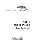
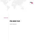
Pathport Model 6182 Touring Edition
User Manual
Version 1
May 2009
Product Description
The Pathway Connectivity Pathport® model 6182 Touring Edition is a one-port DMXover-Ethernet node, intended for use in entertainment and architectural lighting systems
employing DMX512 as the control protocol. The TE can either output or input 512
channels of DMX.
The Touring Edition (TE) node may be configured using Pathport Manager software (freely
downloadable from the Pathway Connectivity website) or by using the three-button/LCD
screen interface on its front. Certain signal testing and RDM tools are only available from
the three-button/LCD interface.
This manual describes the three-button/LCD interface. Please refer to the Pathport
Manager manual for instructions on configuring the Touring Edition via software.
Protocols Supported
Installation
Power
Menu Navigation and Parameter Configuration
Network Settings
Port Settings
DMX Port Monitor
RDM Tools
Test DMX Output
Changing the Battery
1
Pathway Connectivity Solutions
#103 – 1439 17 Ave SE Calgary AB T2G 1J9
P: +1 403-243-8110 F: +1 403-287-1281
www.pathwayconnect.com
Page
2
2
3
3
4
5
5
6
6
6
Protocols Supported
The Touring Edition supports:
ArtNet
Pathport xDMX Protocol
Strand Shownet
ETC Net2 eDMX (output only)
Streaming ACN (E1.31 sACN)/ETC Net3
The Touring Edition also supports RDM (E1.20 Remote Device Management) as a
controller device. The TE can discover RDM-enabled responders and can report and
reconfigure the DMX start address for those devices.
The TE supports the current DMX standard E1.11 DMX512-A and is backwards
compatible to USITT DMX512 (1990).
Features Supported
The Touring Edition has similar functionality to all other Pathport one-port nodes:
- address up to 128 universes
- discover up to 128 RDM devices
- output patch can be customized to merge/prioritize up to eight input sources
- output patch is definable on a channel-by-channel basis
- DMX output speed is user selectable
- signal loss behavior is user-definable
- cross-fade between inputs on loss of signal within a user-defined time
- will operate on any valid IP address/subnet combination
The Touring Edition also supports these testing features:
- reports incoming and outgoing DMX levels
- DMX output test drives user-selected channel levels up and down
- performs discovery and start address editing of RDM-enabled devices
Installation
The Touring Edition ships with a rear-mounted hanging bracket which will accept a ½”
(12.5mm) bolt, and is intended to be suspended using a standard C-Clamp or similar pipe
hanger. A separate anchor point is provided for a secondary safety. The hanging bracket
may be rotated in 90 degree increments.
The TE has an IP54 enclosure rating when mounted so that the cable connections
point straight down.
2
Pathway Connectivity Solutions
#103 – 1439 17 Ave SE Calgary AB T2G 1J9
P: +1 403-243-8110 F: +1 403-287-1281
www.pathwayconnect.com
Power
The Touring Edition will operate on IEEE802.3af Power-over-Ethernet (PoE) as a class I
device, drawing less than 5 watts. It will also operate on a standard 9V battery (included).
The TE will autosense the presence of PoE and will use it in preference to the battery.
However, the TE will not switch to battery if PoE is lost.
When operating on battery, the TE will shut down after 30 seconds without a button
push. One 9V battery will provide at least 30 minutes of configuration operations. For
normal show operation, the TE is intended to run on PoE.
Wiring Connections and Indicators
The TE has two connections: a female RJ45 Ethernet jack and a female 5-pin XLR jack for
DMX. The female XLR means the TE is natively a DMX output device, but the port
direction can be easily changed by the user.
The Ethernet jack will accept a standard male RJ45 connector or a Neutrik
Ethercon® connector.
The TE has two indicator LEDs beside the jacks. A blue LED indicates an active
network connection. A green LED indicates active DMX input or output, dependent on the
DMX port direction.
Display
The Touring Edition has a two-line, 16-character LCD display. In normal operation, the
backlight is turned off. The top line of the display will show the node’s name (if it has one)
or the node’s IP address by default. The lower line will show the universe number or patch
name and the DMX status (IdleOut/LiveOut or IdleIn/LiveIn).
Pressing any button will cause the backlight to come on. Pressing any button again
will cause the TE to enter the menu system.
Menu Navigation and Parameter Configuration
The three buttons below the LCD screen provide menu navigation. Typically, the left
button is NEXT and will display the next choice; while the middle button is OK, accepting
the displayed option or choice, and the right button is ESC, to go back a step without
making changes. Other uses of the keys are noted below.
Configuration changes must be explicitly saved (by pressing a SAVE button) to take
effect. The ESC button or a battery time out will cause changes to be lost.
3
Pathway Connectivity Solutions
#103 – 1439 17 Ave SE Calgary AB T2G 1J9
P: +1 403-243-8110 F: +1 403-287-1281
www.pathwayconnect.com
Top Level Menu
There are five choices at the top menu level, when the node is set as an output device:
- Network Settings
- Port Settings
- DMX Port Monitor
- RDM Tools
- Test DMX Output
Press the NEXT button to scroll through the choices. Press OK select. ESC exits the menu
system. The last two menu choices are not shown when the node is set as an input device.
Network Settings
Nine options may be configured from network settings.
1. IP Address. The address is shown on the upper display line. The left button
allows editing, the right button exits without saving. Press EDIT. The first octet of the IP
address will blink. Change the number by pressing the left button for UP and the middle
button for DOWN. Press the right button NEXT to accept the value for that octet and to
move onto the next octet. Pressing NEXT a fifth time will bring up the option to save the
new address. Once saved, press ESC to return to the top menu.
2. Subnet Mask. The subnet mask is shown on the upper display line. The left
button allows editing, the right button exits without saving. Press EDIT. The first octet of
the subnet mask will blink. Change the number by pressing the left button for UP and the
middle button for DOWN. Press the right button NEXT to accept the value for that octet
and to move onto the next octet. Pressing NEXT a fifth time will bring up the option to
save the new subnet mask. Once saved, press ESC to return to the top menu.
3. Default Gateway. The default gateway address is shown on the upper display
line. The left button allows editing, the right button exits without saving. Press EDIT. The
first octet of the default gateway will blink. Change the number by pressing the left button
for UP and the middle button for DOWN. Press the right button NEXT to accept the
value for that octet and to move onto the next octet. Pressing NEXT a fifth time will bring
up the option to save the new default gateway. Once saved, press ESC to return to the top
menu.
4. Tx Data Protocol (transmit protocol). This option determines what protocol the
node will use to send DMX information over the Ethernet wire, ie when the node is acting
as an input device. Pressing OK when the screen reads “Tx Data Protocol”, will cause the
current transmit protocol to be displayed. Press EDIT, then use the UP/DOWN buttons
to scroll through the choices. Pressing NEXT allows the displayed choice to be saved.
4
Pathway Connectivity Solutions
#103 – 1439 17 Ave SE Calgary AB T2G 1J9
P: +1 403-243-8110 F: +1 403-287-1281
www.pathwayconnect.com
Once saved, press ESC to return to the top menu. Only one transmit protocol may be
selected (enabled) at a given time.
5 thru 9. Receive protocols. Because a Pathport node can listen for multiple
protocols at the same time, the five choices are presented serially. To activate a specific
protocol, press OK. Its current status (disabled/enabled) will be displayed. Press EDIT
then use the UP/DOWN buttons to change it. Pressing NEXT allows the new choice to be
saved. Once saved, press ESC to return to the top menu. One, some or all receive
protocols may be enabled at the same time without performance penalty.
Port Settings
Three options may be configured from port settings.
1. Port Direction. This option determines if the node will act as an input or output
device. Press OK. Its current direction (DMX Output/DMX Input) will be displayed.
Press EDIT then use the UP/DOWN buttons to change direction. Pressing NEXT allows
the new choice to be saved. Once saved, press ESC to return to the top menu.
2. Patch/Universe. This option sets a simple, single universe patch. Complex
universes that include merging and/or prioritization can only be set using Pathport Manager
software. Refer to the software manual for generating custom patches.
Press OK. The current universe number will be displayed or, if a complex patch is
in use, the screen will read “Custom:” followed by the universe name. Press EDIT then use
the UP/DOWN buttons to scroll through the 128 standard, basic patches. Pressing NEXT
allows the new choice to be saved. Once saved, press ESC to return to the top menu.
Saving the patch overwrites all previous patch information.
3. DMX Speed. This option sets the DMX output refresh rate. Default is “Fast”,
which equals 40 packets per second. The choices are Slow (32pps), Medium(37pps), Fast 40
pps) and Max (44pps).
Press OK. The current output speed will be displayed. Press EDIT then use the
UP/DOWN buttons to change. Pressing NEXT allows the new choice to be saved. Once
saved, press ESC to return to the top menu.
DMX Port Monitor
This option reports DMX input or output levels, depending on the port direction setting.
The top line of the display shows a starting channel number, then four DMX levels. The
DMX level closest to the channel number corresponds to that channel. The other three are
the channel number ascending from the start channel number. Press UP/DOWN to change
the DMX start channel. Level information is shown as a percentage.
5
Pathway Connectivity Solutions
#103 – 1439 17 Ave SE Calgary AB T2G 1J9
P: +1 403-243-8110 F: +1 403-287-1281
www.pathwayconnect.com
RDM Tools
This option is only available when the node is configured to be an output device.
RDM Tools performs a discovery, and then lists all discovered RDM-enabled
devices attached to the port. The DMX start address of each discovered device can be
displayed and edited.
Press OK to begin discovery. Once discovery is complete, the total number of
devices found will be reported. If no devices are discovered, the message “None found” will
be shown.
After three seconds, the device with the lowest serial number will be displayed. The
device appears on the upper line of the display with a two-letter manufacturer identifier,
followed by the serial number.
Pressing the middle ID button will cause the device to start its identify behaviour
(typically an indicator light or screen will flash). Press EDIT to change its DMX start
address. Pressing NEXT allows the new choice to be saved. Once saved, press ESC to
return to the device list.
Initiating RDM Discovery from the three-button interface will override a ‘disabled’
setting previously sent to the node from Pathport Manager software.
Test DMX Output
This option is only available when the node is configured to be an output device.
Press OK and “Chan” with a blinking number “1” will appear on the upper line of
the display. Use the UP/DOWN buttons to select the desired DMX channel to test, then
push NEXT. (Press DOWN once to select ALL channels.) Press and hold the UP button to
ramp up the DMX value to full. From full, the value will drop to zero then ramp up again.
Press and release the FADE button to have the node fade the selected channel to full then
back down again.
DMX values are shown between 0 and 255. Press ESC to return to the top menu.
Changing the Battery
Using a small Phillips screwdriver, remove the two screws next to the Pathway label on the
rear of the TE. Gently remove the battery cover plate. Carefully remove the old battery
from the connector and replace with a new 9V battery. Observe correct polarity!
Replace the cover plate and reinstall the screws.
For any questions or clarifications, please contact [email protected].
6
Pathway Connectivity Solutions
#103 – 1439 17 Ave SE Calgary AB T2G 1J9
P: +1 403-243-8110 F: +1 403-287-1281
www.pathwayconnect.com