1
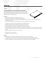
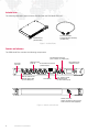
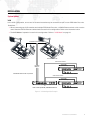
WWW.PRG.COM
PRG NODE PLUS
USER MANUAL
AutoPar®, Bad Boy®, PRG Series 400®, Mbox Extreme®, OHM™, V476™, V676™, Virtuoso®, Virtuoso® DX, Virtuoso® DX2,
and VL6C+™ are trademarks of Production Resource Group, LLC, registered in the U.S. and other countries.
All other brand names which may be mentioned in this manual are trademarks or registered trademarks of their respective companies.
This manual is for informational use only and is subject to change without notice. Please check www.prg.com for the latest version.
PRG assumes no responsibility or liability for any claims resulting from errors or inaccuracies that may appear in this manual.
PRG Node Plus User Manual
Version as of: October 19, 2011
PRG part number: 02.9801.0301 D
Production Resource Group
Dallas Office
8617 Ambassador Row, Suite 120
Dallas, Texas 75247
www.prg.com
PRG Node Plus User Manual
©2007-2011 Production Resource Group, LLC. All Rights Reserved.
IMPORTANT INFORMATION
Safety Notice
It is extremely important to read ALL safety information and instructions provided in this manual and any
accompanying documentation before installing and operating the products described herein. Heed all cautions and
warnings during installation and use of this product.
Safety symbols used throughout this manual are as follows:
CAUTION advising of potential damage to product.
WARNING advising of potential injury or death to persons.
WARNING: INSTRUCTIONS FOR CONTINUED PROTECTION AGAINST ELECTRICAL SHOCK
1) This equipment is designed for dry locations only. Exposure to rain or moisture may damage the equipment and/
or cause injury to persons.
2) Disconnect power before servicing.
3) Servicing to be performed by qualified PRG personnel only.
WARNING: RF INTERFERENCE
1) This is a Class A product. In a domestic environment this product may cause radio interference, in which case, the
user may be required to take adequate measures.
Revision History
This manual has been revised as follows:
Version
Release Date
Notes
BASIC
April 16, 2007
Initial Release
A
April 30, 2007
Miscellaneous revisions and corrections.
B
June 11, 2007
Added Series 400 system configuration details.
C
November 15, 2010
D
October 19, 2011
Updated book format. (No changes to technical information.)
Changed product name from "Virtuoso Node Plus" to "PRG Node Plus."
Added Vx76 system details.
Updated and expanded Art-Net (Series 400) system details.
Added Stand-Alone Software Loader instructions.
PRG NODE PLUS USER MANUAL
1
TABLE OF CONTENTS
Introduction
About This Guide .......................................................................................................................................................................... 3
Additional Documentation ............................................................................................................................................................ 3
Customer Service ......................................................................................................................................................................... 4
Description
Overview ....................................................................................................................................................................................... 5
Included Items .............................................................................................................................................................................. 6
Controls and Indicators ................................................................................................................................................................ 6
Installation
System Options ............................................................................................................................................................................ 7
Vx76....................................................................................................................................................................................... 7
Virtuoso Standard Ethernet ................................................................................................................................................... 8
Virtuoso NIF........................................................................................................................................................................... 9
Art-Net (Series 400) ............................................................................................................................................................. 10
AC Input...................................................................................................................................................................................... 10
Power Up Procedure .................................................................................................................................................................. 10
Configuration
Software Initialization.................................................................................................................................................................. 11
Working Around Performance Limitations .................................................................................................................................. 12
Vx76/Virtuoso Console Setup..................................................................................................................................................... 13
Operation
Using the Menu Display.............................................................................................................................................................. 14
Reset........................................................................................................................................................................................... 14
Operating Modes Overview ........................................................................................................................................................ 15
Important Note Regarding the Series 400 Setup Screen in Vx76 and Virtuoso Modes ............................................................. 15
Vx76 Mode.................................................................................................................................................................................. 16
Virtuoso Mode ............................................................................................................................................................................ 17
Art-Net (Series 400) Mode .......................................................................................................................................................... 18
Stand-Alone Software Loader
Overview ..................................................................................................................................................................................... 19
Using the VirtuosoLoader Application ........................................................................................................................................ 19
Specifications
Technical Specifications ............................................................................................................................................................. 21
2
PRG NODE PLUS USER MANUAL
INTRODUCTION
About This Guide
This guide provides necessary information regarding product safety, installation, and operation for the following PRG
equipment:
+ PRG Node Plus (20.9801.0300)
Familiarizing yourself with this information will help you get the most out of your PRG product.
WARNING: It is important to read ALL accompanying safety and installation instructions to avoid damage to
the product and potential injury to yourself or others.
Additional Documentation
For more information regarding the use of Node Plus units in PRG systems, refer to the following PRG manuals:
+ V676™ / V476™ Control Console User Manual (02.9814.0001.xx)
+ Virtuoso® Series Control Console User Manual (02.9651.0001.xx)
+ PRG Series 400® Power and Data Distribution System User Manual (02.9680.0001.xx)
+ PRG Lighting Systems Networking Guide (02.3004.1000.0)
For extended service information, refer to the following PRG manual:
+ PRG Node Plus Service Manual (02.9801.0310)
For more information regarding DMX512 systems, refer to the DMX512/1990 & AMX 192 Standards publication
available from United States Institute for Theatre Technology, Inc. (USITT).
USITT
6443 Ridings Road
Syracuse, NY 13206-1111 USA
1-800-93USITT
www.usitt.org
For more information regarding Art-Net protocol, refer to the specification for Art-Net II Ethernet Communication
Standard available from Artistic Licence Ltd.
Artistic Licence (UK) Ltd (Registered Office)
24 Forward Drive, Christchurch Avenue,
Harrow, Middlesex, HA3 8NT, United Kingdom
+44 (0)20 88 63 45 15 (phone)
+44 (0)20 84 26 05 51 (fax)
www.artisticlicence.com
For additional documentation, please visit our support tech center at: www.prg.com/support
PRG NODE PLUS USER MANUAL
3
Customer Service
For technical assistance, contact the PRG International Service Center or contact your nearest PRG office. Contact
information for all PRG office locations can be found on our website at: www.prg.com/about-us/locations/
PRG Dallas (International Service)
8617 Ambassador Row, Suite 120
Dallas, Texas 75247 USA
Phone: 214.630.1963
Fax: 214.630.5867
Service Fax: 214.638.2125
Service Email: [email protected]
For additional resources and documentation, please visit our website at: www.prg.com
4
PRG NODE PLUS USER MANUAL
DESCRIPTION
Overview
The PRG Node Plus provides a powerful and convenient interface
between Vx76, Virtuoso, or Art-Net compatible control consoles, pixel
mapping from media servers, and subsequent control equipment which
require either Art-Net or DMX512 control signals. The unit accepts high
level commands in either Vx76, Virtuoso, or Art-Net protocol and converts
the data into six universes of DMX512.
Features:
+ Accepts Vx76, Virtuoso, and Art-Net control protocols.
+ Compatible with 10Base-T or 100Base-TX standard signals.
+ Automatic detection and mode configuration according to input signal type when used with either a Vx76 or
Virtuoso control console.
+ Can be used as an Art-Net-to-DMX translator device when loaded with Series 400 software.
+ One Ethernet (Art-Net) output port supporting up to six DMX512 universes.
+ Six DMX512 serial output ports supporting one DMX512 universe each.
+ LEDs indicating Link, TX data, and RX data status for all Ethernet ports.
+ LEDs indicating DMX Tx, RDM Tx, and RDM Rx data status for all DMX ports.
+ Display support for configuration of the address, configuration of Art-Net outputs in Series 400 Mode, real-time
monitoring of DMX512 data on each output, display of network error information, and display of current software
version.
+ Neutrik® PowerCon® connector for input AC supply.
+ Front panel DC power status LED.
+ Standard 1U 19" rack mount chassis.
Modes:
The PRG Node Plus unit operates in one of three modes: Vx76, Virtuoso, or Series 400.
+ In Vx76 Mode, the unit will accept Vx76 protocol and generate both Art-Net and DMX512 outputs.
+ In Virtuoso Mode, the unit will accept Virtuoso protocol and generate both Art-Net and DMX512 outputs.
+ In Art-Net (Series 400) Mode, the unit will accept Art-Net protocol and convert it to DMX512.
PRG NODE PLUS USER MANUAL
5
Included Items
The following illustration shows all items included with the PRG Node Plus unit.
AC Line Cord 208V
PowerCon® Cable Assembly
(25.9801.0214)
PRG Node Plus
(20.9801.0300)
Figure 1: Included Items
Controls and Indicators
The PRG Node Plus contains the following components:
RJ-45 Ethernet Connector
(Vx76, Virtuoso, or Art-Net Input)
1
ON
Menu Display and
Software Control
DMX512 Output
Ports (6)
RJ-45 Ethernet Connector
(Art-Net Output)
DC Power
Input LED
2
3
4
5
DMX OUT
6
VIRTUOSO
LINK
DMX Tx
Tx
RDM Tx
Rx
RDM Rx
DMX OUTPUTS
MODEL 20-9801-0300
Push to Select
ETHERNET
FRONT PANEL
DMX Tx, RDM Tx and
RDM Rx Status LEDs
(for each DMX port)
Reset Button
Link, Tx Data, and Rx
Data Status LEDs
(for each Ethernet port)
REAR PANEL
Neutrik Connector Allows connection of AC Line Cord
208V PowerCon Cable (supplied).
Figure 2: Controls and Indicators
6
PRG NODE PLUS USER MANUAL
INSTALLATION
System Options
Vx76
In the Vx76 configuration, one or two Vx76 control consoles may be connected to one or more PRG Node Plus units.
Guidelines:
+ When connecting two Vx76 consoles and multiple PRG Node Plus units, a 100Mb Ethernet switch or hub must be
used. Standard CAT5e Ethernet cables should be used in this configuration. Refer to the illustration below.
+ The Vx76 Mode of operation is used in this configuration. Refer to "Vx76 Mode" on page 16.
CAT5e Ethernet Cables
V676 CONSOLE "B"
V676 CONSOLE "A"
Vx76 Protocol CAT5e *
Art-Net DMX
(to S400 Rack)
100 Meter
Maximum
PRG NODE PLUS
* PRG Belden Ethernet cable or equivalent.
6x XLR DMX512 Data Cable
Vx76 Protocol CAT5e *
Art-Net DMX
(to S400 Rack)
PRG 10-PORT (FIBER) ETHERNET SWITCH
PRG NODE PLUS
or
PRG 7-PORT (COPPER) ETHERNETSWITCH
6x XLR DMX512 Data Cable
Figure 3: Vx76 Configuration Example
PRG NODE PLUS USER MANUAL
7
Virtuoso Standard Ethernet
In the Virtuoso Standard Ethernet configuration, one or two Virtuoso control consoles may be connected to one or
more PRG Node Plus units.
Guidelines:
+ When connecting one Virtuoso console and one PRG Node Plus unit, an Ethernet Crossover cable (25.9651.0566)
must be used instead of an Ethernet switch or hub.
+ When connecting two Virtuoso consoles and multiple PRG Node Plus units, a 100Mb Ethernet switch or hub must
be used. Standard CAT5e Ethernet cables should be used in this configuration. Refer to the illustration below.
+ The Virtuoso Mode of operation is used in this configuration. Refer to "Virtuoso Mode" on page 17.
+ The PRG Node Plus unit can only be used with Virtuoso consoles running software version 5.6 or greater.
CAT5e Ethernet Cables
VIRTUOSO CONSOLE "B"
VIRTUOSO CONSOLE "A"
Virtuoso Protocol CAT5e *
Art-Net DMX
(to S400 Rack)
100 Meter
Maximum
PRG NODE PLUS
* PRG Belden Ethernet cable or equivalent.
6x XLR DMX512 Data Cable
Virtuoso Protocol CAT5e *
Art-Net DMX
(to S400 Rack)
PRG 10-PORT (FIBER) ETHERNET SWITCH
PRG NODE PLUS
or
PRG 7-PORT (COPPER) ETHERNET SWITCH
6x XLR DMX512 Data Cable
Figure 4: Virtuoso Standard Ethernet Configuration Example
8
PRG NODE PLUS USER MANUAL
Virtuoso NIF
In the Virtuoso NIF configuration, one or two Virtuoso control consoles may be connected to one or more PRG Node
Plus units through a NIF.
Guidelines:
+ When connecting one Virtuoso console/NIF and one PRG Node Plus unit, an Ethernet Crossover cable
(25.9651.0566) must be used instead of an Ethernet switch or hub.
+ When connecting two Virtuoso consoles/NIFs and up to three PRG Node Plus units, a 100Mb Ethernet switch or
hub must be used. Standard CAT5e Ethernet cables should be used in this configuration. Refer to the illustration
below.
+ The Virtuoso Mode of operation is used in this configuration. Refer to "Virtuoso Mode" on page 17.
+ The PRG Node Plus unit can only be used with Virtuoso consoles running software version 5.6 or greater.
Fiber Optic Cable **
Virtuoso Protocol CAT5e *
NIF UNIT +
Art-Net DMX
(to S400 Rack)
A
B
PRG NODE PLUS
6x XLR DMX512 D ata Cable
Virtuoso Protocol CAT5e *
CAT5e
Art-Net DMX
(to S400 Rack)
PRG 10-PORT (FIBER) ETHERNET SWITCH
PRG NODE PLUS
or
PRG 7-PORT (COPPER) ETHERNET SWITCH
6x XLR DMX512 D ata Cable
Fiber Optic Cable **
* PRG Belden Ethe rnet cable or equivalent.
** Console may be connected by CAT5e Ethernet
Cable instead of F iber Optic Cable.
+ Each NIF has a limit of 3 Node Plus connections.
VIRTUOSO CONSOLE "A"
VIRTUOSO CONSOLE "B"
Figure 5: Virtuoso NIF Configuration Example
PRG NODE PLUS USER MANUAL
9
Art-Net (Series 400)
In the Art-Net (Series 400) configuration, an Art-Net compatible control console may be connected to one or more
PRG Node Plus units.
Guidelines:
+ When connecting an Art-Net compatible console and multiple PRG Node Plus units, a 100Mb Ethernet switch or
hub must be used. Standard CAT5e Ethernet cables should be used in this configuration. Refer to the illustration
below.
+ The Series 400 Mode of operation should be used in this configuration. Refer to "Art-Net (Series 400) Mode" on
page 18.
+ When using a Node in this way, there are some important considerations that should be observed during setup
and operation. Refer to "Configuration" on page 11.
+ When using a Node as an Art-Net-to-DMX device, note that the Art-Net output does not pass data; it only mirrors
the DMX outputs. It is not possible to place the Art-Net output on the same network as the Art-Net input.
CAT5e Ethernet Cable *
* PRG Belden Ethernet cable or equivalent
PRG NODE PLUS
6x XLR DMX512 Data Cable
CAT5e
DMX512-OVER-ETHERNET
(ARTNET) CONSOLE
Art-Net Protocol
PRG 10-PORT (FIBER) ETHERNET SWITCH
PRG NODE PLUS
or
PRG 7-PORT (COPPER) ETHERNET SWITCH
6x XLR DMX512 Data Cable
Figure 6: Art-Net (Series 400) Configuration Example
AC Input
Connect the AC Line Cord power cable assembly to the rear panel Neutrik® PowerCon® connector.
MANUFACTURED BY:
THIS DEVICE COMPLIES WITH PART 15 OF THE FCC RULES. OPERATION IS SUBJECT TO
THE FOLLOWING TWO CONDITIONS: (1) THIS DEVICE MAY NOT CAUSE HARMFUL
CONFORMS TO
ANSI/UL STD 60950-1
R
INTERFERENCE, AND (2) THIS DEVICE MUST ACCEPT ANY INTERFERENCE RECEIVED,
INCLUDING INTERFERENCE THAT MAY CAUSE UNDESIRED OPERATION.
C
SUITABLE FOR DRY LOCATIONS ONLY
8617 AMBASSADOR ROW, DALLAS, TX 75247
Made in U.S.A.
INPUT RATING:
100-265VAC, 50/60 Hz, 1A MAX
0
0
OPERATING TEMPERATURE RANGE: -20 C to 50 C
LI
ST E D
3077774
US
CERTIFIED TO
CAN/CSA STD C22.2 NO. 60950-1
DENAN Category B
PS
E
JAPAN
REAR PANEL
Neutrik Connector
Figure 7: Connecting AC Input Cable
Power Up Procedure
To power up the Node Plus unit and set its address:
Step 1. Once the AC input cable is connected and power is applied, the unit will receive power. (It does not have a
power on/off switch.)
Step 2. Using Menu Display controls, set Node Plus thumbwheel starting address (refer to "Operation" on page 14).
Ensure that addresses are unique among all Nodes in system.
10
PRG NODE PLUS USER MANUAL
CONFIGURATION
Software Initialization
The Node Plus requires different software to run in each type of system/mode configuration. For the Node Plus, the
currently loaded software is shown at the top of the main menu screen. It will indicate either "Virtuoso Node", "Vx76
Node", or "Series 400 Node" as shown in the example below.
The Virtuoso and Vx76 consoles will automatically update the Node
software when it is connected to the system. However, when used
with Art-Net, the Node software must be loaded with Series 400
software.
Current Software Type
Series 400 Node
The Series 400 software should always be loaded in the shop. This
can be accomplished by one of three methods:
+ Series 400 Menu Loader (Breaker Module). Refer to the Series
400 System User manual for instructions.
+ S400 Tools Application (S400Loader). Refer to the Series 400
Tools User manual for instructions.
a
001
000 001 002 003 -- -Info
Addr
Setup
NODE PLUS MENU DISPLAY
+ Stand-Alone Loader (VirtuosoLoader). Refer to "Stand-Alone
Software Loader" on page 19.
S400 MENU LOADER
S400 TOOLS LOADER
STAND-ALONE LOADER
Software Info
a
Version: 3.0
r115
Date: 11/24/09
11:24
Boot: 1.1
r4
Date: 06/27/05
12:10
i/f
A
B
exit
Stored BO/Node Info a
Version: 3.0
r23
Date: 07/15/08
09:18
Node: 02/27/09
11:24
i/f
>BO >Nod
exit
CAUTION! Since the Virtuoso and Vx76 systems will update the Node software automatically, be careful not to
connect a Series 400 loaded Node to a console network or else the Series 400 software will be replaced!
The Series 400 software version that is currently loaded in the Node Plus
can be checked at any time by accessing the "Information" screen in the
menu display. An example Information screen is shown at the right:
Information
a
Vers: 05/07/10 16:00
Boot: OK
NetId 00C0 5E02 048B
NetSta Info Addr
NODE PLUS MENU DISPLAY
PRG NODE PLUS USER MANUAL
11
Working Around Performance Limitations
The embedded processor in the Node has limitations with its buffering and communication processing, and often
cannot keep up with modern computers that send data packets very close together.
In a Virtuoso or Vx76 system, the Node is doing all the calculations to generate DMX512 for the control channels
patched to it. In cases where large numbers of fixtures generating intensity-based traffic - such as LEDs - are patched
to the Node, the processing limitations will become evident during fast effects across many channels. A typical
symptom would be effects not keeping up or continuing to run after being stopped on the console.
In an Art-Net system, the Node is receiving network DMX512 packets and outputting the information on the DMX
ports. The limitation here is in the Node's limited available network packet buffering. If the network packets for
consecutive Art-Net universes are spaced less than about 100 microseconds apart, the Node may drop some of the
packets since they are being sent faster than the Node can receive and process them. A typical symptom would
appear as temporary freezes in the DMX outputs. (Note that this is generally not a problem when the universes are
input to the network by multiple sources.)
Suggestions:
+ Virtuoso/V676 Control Systems - The maximum number of control channels patched to a given Node should not
exceed 250 where there are a large number of LED fixtures patched to the Node.
+ Art-Net Systems - Configure the Art-Net source to increase the time between consecutive network packets, or to
interleave/alternate the universes in a different order. Most of the fast Art-Net devices allow adjustment of their
Art-Net output timing, so this can help to resolve any problems.
+ Spread out the universes mapped to a single Node, since the Node can discard unneeded universes more quickly
than processing mapped universes. For example, it is better to map every third universe to a Node instead of a
string of six consecutive universes.
+ As a general rule, limit the maximum number of universes a Node must process to four (4).
Note: If merging is enabled, the Node must listen to two universes (or more) per output, so the number of output
universes may need to be reduced to one or two with a high-speed Art-Net source. (Refer to "Merge Options" on
page 18.)
CAUTION! Since there can be quite a bit of variation in Art-Net controllers, it is always a good idea to test the
controller with all networking gear and Art-Net devices prior to a show situation!
12
PRG NODE PLUS USER MANUAL
Vx76/Virtuoso Console Setup
When using a PRG Node Plus with a PRG Vx76 or Virtuoso console, the Node can be set up using the console’s DMX
Setup window.
Step 1. At console, patch DMX fixtures and assign a DMX universe.
Step 2. At Setup menu, select DMX Setup. (DMX Setup window will open.)
Step 3. Select desired DMX universe.
Step 4. Enter Node thumbwheel address in "Thumb" field and select Node output (1-6)
in pop-up menu.
Step 5. Click Set button to assign universe to selected Node output.
Step 6. If patching sequential Nodes and outputs, pressing the [Return] button on the
keyboard will auto increment the patch. If not sequential, repeat Steps 3
through 5.
DMX Universe (A-ZZ)
Must be assigned to a
DMX Host (Node, etc.)
DMX512 channel
assignments for
selected universe
Orange highlights
show DMX channel
range for selected
fixtures
Node Address
DMX Output of Node
Enable/Disable Patch Editing
Set Button Press to enter current settings
and advance to the next line
Troubleshooting
Symptom
Indication
Remedy
Node Plus online,
but no control.
Appears in console configuration
window, but channels are not online.
Incorrect patch: verify Node Plus address and that universes
are set to ‘Node’ not ‘Con’ in DMX Setup window.
PRG NODE PLUS USER MANUAL
13
OPERATION
Using the Menu Display
The PRG Node Plus includes a display menu for configuring the unit and checking system status. The menu system
can be navigated using the joystick controller, which can be moved left, right, up, and down, and pushed in. In
general, left and right movements navigate the top level menus at the bottom of the display. Pushing in the joystick
enables editing for the current screen. Pushing in while editing, saves changes and exits.
Vx76 Node
Display
001
000 001 002 003 -- -DmxMon
Vx76
NetSta
Push to Select
Previous Menu
Joystick Navigation Control
Next Menu
Current Menu
Figure 8: Menu Display and Joystick
Reset
In the event a software reset is necessary, the Reset button may be pressed. The Reset button is recessed into the
front panel as shown.
1
ON
2
3
4
5
DMX OUT
6
Tx
RDM Tx
Rx
RDM Rx
DMX OUTPUTS
MODEL 20-9801-0300
Reset Button
Figure 9: Reset Button Location
14
PRG NODE PLUS USER MANUAL
VIRTUOSO
LINK
DMX Tx
Push to Select
ETHERNET
Operating Modes Overview
The PRG Node Plus unit operates in one of three modes: Vx76, Virtuoso, or Art-Net (Series 400). The mode will
depend on the system setup.
+ Vx76 Mode - In this mode, the unit will accept Vx76 protocol and generate both Art-Net and DMX512 outputs.
Vx76
Protocol
PRG NODE PLUS
[ Vx76 Mode ]
Art-Net and DMX512
+ Virtuoso Mode - In this mode, the unit will accept Virtuoso protocol and generate both Art-Net and DMX512
outputs.
Virtuoso
Protocol
PRG NODE PLUS
[ Virtuoso Mode ]
Art-Net and DMX512
+ Art-Net (Series 400) Mode - In this mode, the unit will accept Art-Net protocol and convert it to DMX512. (When
used with the Series 400 rack, the Node will follow the selected A, B, or C system.)
Art-Net
Protocol
PRG NODE PLUS
[ Art-Net Series 400 Mode ]
DMX512
Important Note Regarding the Series 400 Setup Screen in Vx76 and Virtuoso Modes
When operating in either the Vx76 or Virtuoso mode, a legacy "Series 400 Setup" screen is still available in the menu.
This is an obsolete screen and should no longer be used for Series 400 (Art-Net) setup. The new "Series 400 Setup"
screen is available when the Node has been loaded with Series 400 software, and should be used to setup the Art-Net
system as detailed in "Art-Net (Series 400) Mode" on page 18.
a
Series 400 Setup
Series 400 Setup
000 001 002 003 004 005
000 001 002 003 004 005
numeric
numeric noMerge
Info
Ser400
DmxMon
OBSOLETE "SERIES 400 SETUP" MENU
- Available in Vx76 and Virtuoso Modes DO NOT USE!
Addr Setup DmxMon
NEW "SERIES 400 SETUP" MENU
- Available in Series 400 Mode USE FOR ART-NET SETUP
PRG NODE PLUS USER MANUAL
15
Vx76 Mode
When the Node Plus is connected to a Vx76 series console, the menu system will provide "Vx76" screens which can
be used to set up and monitor the Vx76 system.
Vx76 Node Screen
The Vx76 Node screen displays the thumbwheel address and mapped
DMX512 universes (as patched from the console). In the sample image at
the right, this unit has been set to thumbwheel 001, and Vx76 universes
A-D have been patched to outputs 000 through 003 of this Node.
To edit the thumbwheel address, press the joystick. The first digit will be
highlighted. Use up/down to change the digit, left/right to move to
another digit, and press down to save and exit.
Vx76 Node
001
000 001 002 003 -- -DmxMon
Vx76
NetSta
Network Stats
The Network Stats screen displays transmit and receive statistics since
power-up.
This screen is not editable.
TX #: successful transmits
T/O: transmit time-outs
Mem: transmit memory errors
RX #: successful receives
Flag: receive invalid flag error
Buf: receive buffer shortage
fail: transmit failures
HwEr: transmit hardware errors
Apn: transmit buffer errors
HwEr: receive hardware errors
Cksm: receive checksum error
Msg: receive message item shortage
Information
The Information screen displays software version date/time, verification of
valid Boot module, and programmed Network ID.
Network Stats
TX #
T/O
Mem
RX #
Flag
Buf
Vx76
467
0
0
1262
0
0
fail
HwEr
Apn
HwER
Cksm
Msg
NetSta
0
0
0
0
0
0
Info
Information
Vers: 10/06/11 00:48
Boot: OK
NetId 00C0 5E02 04AC
NetSta Info Ser400
This screen is not editable.
DMX Monitor
The DMX Monitor screen displays the data for each active universe.
Press the joystick to cycle through all six ports. This screen is not
editable.
Series 400
The Series 400 screen is an obsolete menu item and should no longer be
used for Series 400 (Art-Net) setup. The new "Series 400 Setup" screen is
available when the Node has been loaded with Series 400 software, and
should be used to setup the Art-Net system as detailed in "Art-Net (Series
400) Mode" on page 18.
DMX Port 1 (000)
001: 000 127 255 127 255
006: 000 000 000 000 000
011: 000 000 000 000 000
016: 000 000 000 000 000
Ser400 DmxMon Vx76
Series 400 Setup
000 001 002 003 004 005
numeric
Info
Ser400
DmxMon
OBSOLETE MENU
16
PRG NODE PLUS USER MANUAL
Virtuoso Mode
When the Node Plus is connected to a Virtuoso series console, the menu system will provide "Virtuoso" screens
which can be used to set up and monitor the Virtuoso system.
Note: The PRG Node Plus unit can only be used with Virtuoso consoles running software version 5.6 or greater.
Virtuoso Node Screen
The Virtuoso Node screen displays the thumbwheel address and mapped
DMX512 universes (as patched from the console). In the sample image at
the right, this unit has been set to thumbwheel 001, and Virtuoso
universes A-D have been patched to outputs 000 through 003 of this
Node.
To edit the thumbwheel address, press the joystick. The first digit will be
highlighted. Use up/down to change the digit, left/right to move to
another digit, and press down to save and exit.
Network Stats
001
000 001 002 003 -- -DmxMon
Virt
NetSta
Network Stats
The Network Stats screen displays transmit and receive statistics since
power-up.
This screen is not editable.
TX #: successful transmits
T/O: transmit time-outs
Mem: transmit memory errors
RX #: successful receives
Flag: receive invalid flag error
Buf: receive buffer shortage
Virtuoso Node
fail: transmit failures
HwEr: transmit hardware errors
Apn: transmit buffer errors
HwEr: receive hardware errors
Cksm: receive checksum error
Msg: receive message item shortage
Information
The Information screen displays software version date/time, verification of
valid Boot module, and programmed Network ID.
TX #
T/O
Mem
RX #
Flag
Buf
Virt
467
0
0
1262
0
0
fail
HwEr
Apn
HwER
Cksm
Msg
NetSta
0
0
0
0
0
0
Info
Information
Vers: 02/22/07 12:36
Boot: OK
NetId 00C0 5E02 03EC
NetSta Info Ser400
This screen is not editable.
DMX Monitor
The DMX Monitor screen displays the data for each active universe.
Press the joystick to cycle through all six ports. This screen is not
editable.
Series 400
The Series 400 screen is an obsolete menu item and should no longer be
used for Series 400 (Art-Net) setup. The new "Series 400 Setup" screen is
available when the Node has been loaded with Series 400 software, and
should be used to setup the Art-Net system as detailed in "Art-Net (Series
400) Mode" on page 18.
DMX Port 1 (000)
001: 000 127 255 127 255
006: 000 000 000 000 000
011: 000 000 000 000 000
016: 000 000 000 000 000
Ser400 DmxMon Virt
Series 400 Setup
000 001 002 003 004 005
numeric
Info
Ser400
DmxMon
OBSOLETE MENU
PRG NODE PLUS USER MANUAL
17
Art-Net (Series 400) Mode
When the Node Plus has been loaded with Series 400 software, the menu system will provide "Series 400" screens
which can be used to set up and monitor the Art-Net system.
Setup
The "Series 400 Setup" screen is used to configure the Art-Net universes,
display options, and merge setting.
+ Universes - Specify the Art-Net universes (A-N) to be received and
translated (such as 000, 001, 002, 003, etc.).
+ Display - Specify whether the universes should be displayed as
numeric, alpha, or hex.
a
Series 400 Setup
000 001 002 003 004 005
numeric noMerge
Addr Setup DmxMon
+ Merge - Specify a merge setting (2-Way, 3-Way, 4-Way) or "no
merge." See below for details.
a
Series 400 Node
Status
The Address, DMX Monitor, and Network Stat screens provide status
feedback for the Art-Net system. These screens are not editable.
+ Address Screen - Shows the current system source (a, b, or c), active
universes, and thumbwheel address. (The thumbwheel address is for
ID purposes only).
+ DMX Monitor Screen - Shows the data for each active universe.
Press the menu toggle switch to cycle through all six ports.
+ Network Stats Screen - Shows transmit and receive statistics since
power-up.
TX #: successful transmits
T/O: transmit time-outs
Mem: transmit memory errors
RX #: successful receives
Flag: receive invalid flag error
Buf: receive buffer shortage
fail: transmit failures
HwEr: transmit hardware errors
Apn: transmit buffer errors
HwEr: receive hardware errors
Cksm: receive checksum error
Msg: receive message item shortage
Information
The Information screen displays software version date/time, verification of
valid Boot module, and programmed Network ID.
This screen is not editable.
001
000 001 002 003 -- -Info
Addr
Setup
DMX Port 1 (000)
a
001: 000 127 255 127 255
006: 000 000 000 000 000
011: 000 000 000 000 000
016: 000 000 000 000 000
Setup DmxMon NetSta
Network Stats
TX #
T/O
Mem
RX #
Flag
Buf
467
0
0
1262
0
0
DmxMon
fail
HwEr
Apn
HwER
Cksm
Msg
NetSta
0
0
0
0
0
0
a
Info
Merge Options
The merge options available on the "Series 400 Setup" screen allow
merging of data for multiple universes assigned to the same number. For
example, if two inputs are set to 001a and 2-way merge is enabled, then
the resulting output for outputs set to universe 001 would be the highest
value for each channel between the two inputs (HTP). If three inputs are
active at 001, the outputs would be disabled.
Options are as follows:
+ noMerge: no universe merging.
(This is the default setting: noMerge = 1.)
+ 2-Way: allows up to 2 universe inputs per universe.
+ 3-Way: allows up to 3 universe inputs per universe.
+ 4-Way: allows up to 4 universe inputs per universe.
18
PRG NODE PLUS USER MANUAL
Information
a
Vers: 05/07/10 16:00
Boot: OK
NetId 00C0 5E02 048B
NetSta Info Addr
When used with the Series 400 rack, the
Node will follow the selected A, B, or C
system. The current system source is
displayed in the top corner of each S400
menu screen. System "a" is the default
system source for Art-Net configurations.
STAND-ALONE SOFTWARE LOADER
Overview
The Virtuoso and Vx76 consoles will automatically update the Node software when it is connected to the system.
However, the stand-alone loader application (VirtuosoLoader) may be used in place of the console to update the
Node. (The application works the same as the console’s update software feature in the Version Info window.)
When used with Art-Net, the Node software must be loaded with Series 400 software. This can be done using the
VirtuosoLoader.
The VirtuosoLoader application will update the connected devices according to the software update *.bin module(s)
contained within its folder. For example, the "Node.srec.bin" module as shown below:
VirtuosoLoader Application Folder
VirtuosoLoader Application
Module
Using the VirtuosoLoader Application
The VirtuosoLoader application will run on any Windows® or Macintosh® computer. However, it may be necessary to
install Java Runtime if the jar file does not run on your computer. It is available from www.java.com.
Step 1. Connect computer to devices using one of the following methods:
SINGLE DEVICE
Ethernet
Mac / PC
Node or Node Plus
MULTIPLE DEVICES
Mac / PC
Ethernet
Ethernet
Switch
Node or Node Plus
Node or Node Plus
Node or Node Plus
PRG NODE PLUS USER MANUAL
19
Step 2. Download or copy the VirtuosoLoader application folder to your computer.
Step 3. Open VirtuosoLoader folder and double-click "VirtuosoLoader.jar" file. (This is a stand-alone Java
application.)
VirtuosoLoader Application
Step 4. Click Start Download button. The module will update all connected devices.
Click to start download
Device & Version
Information
20
PRG NODE PLUS USER MANUAL
SPECIFICATIONS
Technical Specifications
POWER REQUIREMENT:
90 to 264 VAC, 47 to 63 Hz
Draws less than 60 watts continuously.
COOLING:
Convection.
OPERATING TEMP:
-20°C to 50°C (-4°F to 122°F).
INPUT:
One control signal input which is fed from a console providing either Virtuoso or DMXover-Ethernet (Art-Net) protocol.
OUTPUT:
One Art-Net output carrying up to six DMX512 universes.
Six (non-isolated) standard DMX512 serial outputs, each carrying one DMX512 universe.
(Both output protocols are simultaneously active in Virtuoso mode.)
COMM INDICATORS:
Input and output status LEDs indicating DMX Tx, RDM Tx and RDM Rx data (DMX ports),
and Link, Tx data and Rx data (Ethernet ports).
POWER INDICATOR:
Green LED indicating that DC power has been applied.
CONTROL:
Built-in Menu Display with joystick and button controls.
HOUSING:
Standard 1U 19" rack mount chassis.
WEIGHT:
4.5 lbs (2.04 kg)
COMPLIANCE:
ETL and CSA Standards in CE and DENAN category B, Circle PSE.
1.72"
(44 mm)
PRG NODE PLUS USER MANUAL
21
Notes
22
PRG NODE PLUS USER MANUAL
PRG Node Plus User Manual
Version as of: October 19, 2011
PRG part number: 02.9801.0301 D
Production Resource Group
Dallas Office
8617 Ambassador Row, Suite 120
Dallas, Texas 75247
www.prg.com