1
Probe Installation
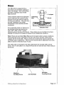
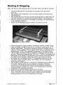
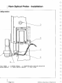
The Z-rail has a probe holder built into
the bottom of the rail. To install a hard
probe:
1. Loosen the locking lever on the
side of the Z-rail.
2. Insert the probe shank into the
Z-rail. A spring plunger detent
will help to hold the probe in
place (the probe tip is normally
3" (75mm) from the end of the
Z-rail).
3. Tighten the locking lever. Be
sure the probe is firmly clamped.
4. Adjust the Z-rail counterbalance
control to compensate for the
added weight of the probe. Unlock the Z-axis. Unlock the counterbalance
regulator by pulling the knob outward. Turn the knob clockwise to
increase the lift for heavy probes or counterclockwise for light probes.
When finished, push the knob in.
To install-a Touch Trigger Probe:
1. Loosen the locking lever on the side of the Z-rail.
2. Check the Touch Trigger Probe to be sure it has a stylus tip. If not, obtain
the required tip and install it onto the probe head sensing shaft, securing
the tip with the stylus tool provided. Refer to the probe manufacturer's
documentation for stylus installation instructions.
3. Insert the probe head mounting shaft into the Z-rail until it engages the
detent.
4. Rotate the probe head until the red light indicator faces the front of the
machine.
5. Hold the probe in this position and tighted the locking lever until the
. probe is firmly clamped.
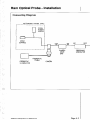
6. Connect the probe head lead to the probe connector located on the Z-rail.
7. If necessary, adjust the Z-rail counterbalance control to compensate for
the change in weight from the probe. The proper tip type must be selected
in the configure screen.
Note: These probe installation procedures are typical and included as an
example. The procedure for installing your probe may differ from these. Refer
to your probe manufacturer's documentation for installation instructions.
Note: Each tip must be qualified before it it used for measurements.
e1996 Brown & Shorpe Mfg. Co. All Rights Re,erved.
Page 3-19










![Manual Audition 4 [By Dr.J.]](http://vs1.manualzilla.com/store/data/005935757_1-4addafd8884e379cc6f9c4cc1fe5fdba-150x150.png)