1
·~~-
.8 . ... . .:. . . .. . . ... . .: '" \.
'~<\''''-\
?
•..
tv
1-
\ :t:t
,_
\...I!:'
USER'S MANUAL
MicroVal®
82-90001-4
~ \""'V- ~ ~
B"0'\.1 VI +-
./101 nL 0'2 0 0
~b
0 -
0
~ '6~ - \ it '6 ?::.
L."ci'
4"-;, 'I
.
L"'2."
THEME
{O
~"oi~
nsM
"'JI
J
@
.
I.B. EN ISO 91101
~ \~
e;;
© 1996 Brown&Sharpe Manufacturing Company
u
u
()
(
'j
"
I"
)'
.. ,
('.
{
'.
)
.,
Contents
CHAPTER 1 - Introduction .._............................................................ 1-1
Foreword ........................................................................................ , 1-3
Warranty ......................................................................................... 1-4
Software Warranty .......................................................................... 1-4
Warranty Service ............................................................................. 1-5
General Safcty ................................................................................. 1-6
Description ...................................................... , ............................... 1-7
Dimensions - Microva1343 .......................................................... 1-12
Dimensions - Microval 454 .......................................................... 1-13
Specifications - Microval343 ....................................................... 1-14
Specifications - Microval454 ....................................................... 1-15
CHAPTER 2 - Construction ............................................................... 2-1
Base ................................................................................................. 2-3
Work Table ..................................................................................... 2-4
Y-Rails ........................................................................................ :... 2-5
Bridge .............................................................................................. 2-6
ZX Carriage .................................................................................... 2-7
Z Rail .............................................................................................. 2·8
Air Control and Filter ...................................................................... 2·9
Air System .................................................................................... 2-10
Air Bearings .................................................................................. 2-11
Measuring System ......................................................................... 2-12
Reference Offsets .......................................................................... 2-13
Probes ............................................................................................ 2-14
TP·ES Probe .................................................................................. 2-14
MIP Probe ..................................................................................... 2-14
Electronic System ......................................................................... 2-15
Controllers ..................................................................................... 2-16
MAN 3 Controller Ports ................................................................ 2-17
Computer with Embedded Board .................................................. 2·17
MieroVal343 & 454 - Basie System ............................................ 2-18
MieroVa1343 & 454 - 2F System ................................................. 2·19
3B System Package - MINTA Computer ..................................... 2-20
3B System Package - AST Computer ........................................... 2-21
MicroVa1343 & 454 - 4M System ............................................... 2·22
CHAPTER 3 _ Operation ................................................................... 3-1
Operator Safety ............................................................................... 3·3
Computer Disks .............................................................................. 3-6
Use & Care: Computer Disks ......................................................... 3-8
Remote Hand Switch ...................................................................... 3-9
Q1996 Brown & Sh''Pe Mfg. Co. All Righ1.!l Re.erved.
Page 0·1
Contents
Using a Mouse .............................................................................. 3-10
Starting & Stopping ...................................................................... 3-13
Moving the Axes ........................................................................... 3-15
Hommg the Machine ..................................................................... 3-16
The Inspection Process ................................................................. 3-18
Probe Installation .......................................................................... 3-19
MeaSuring With a Ball Probe ........................................................ 3-20
Probe Compensation ..................................................................... 3-21
Measuring With an Electronic probe ............................................ 3-22
Touch Trigger Probe Repeatability ............................................... 3-23
Useful Probe Dimensions ............................................................. 3-25
Good Measurement Techniques .................................................... 3-27
CHAPTER 4 - Maintenance ............................................................... 4·1
Machine Maintenance & Safety ...................................................... 4-3
General Safety Practices ................................................................. 4-3
The Machine's Environement ......................................................... 4-3
Electronics ............................................................ , ............. ,............ 4-4
Covers .............. ,", ................ , ................ ,......................................... 4-4
Pneumatics ............................................................. " ............... ,....... 4-4
Maintenance Intervals ..................................................................... 4-5
Daily or Every 8 Hours ................................................................... 4-6
Monthly or 165 Hours ..................................................................... 4-6
Every Three Months or 500 Hours ............................................... ..4-6
Maintenance Log .. :: ............... :::::7.................................................... 4-7
Machine Troubleshooting ............................................................... 4-8
MicroMeasure Troubleshooting .................................................... 4-11
UNIX Boot Prompts ..................................................................... 4-14
PC Support Tips ............................................................................ 4-15
Cleaning Glass Scales ................................................................... 4-17
Changing the Air Filter ................................................................. 4-18
MAN 3 Power Entry Module Assembly ...................................... .4-19
Voltage Selection .......................................................................... 4-19
MAN 3 Powe;r Module Jumper Settings ....................................... 4-20
MAN 3 Power Entry Module Fuse Changing .............................. .4-21
c
c
.)
()
u
(.1
CHAPTER 5 • Glossary ...................................................................... 5-1
CHAPTER A • Ram Optical Probe .................................................. A-1
Installation ..................................................................................... A-I
Mounting Configuration .............................................................. ,' A-2
Connecting Diagram ,..................................................................... A-3
Adjustments ................................................................................... A-4
Qualification ........... " .................. ,................................ ,................ , A-6
Measuring ...................................................................................... A-7
( j
(
11H996 Brown &SharpcMfg: Co. All Righls' ru"crvcd.
CHAPTER 1
Introdu~
Chapter 1: MicroVal User's Manual Inti
['-l-;--M-iel'O¥a1-TJ-ser--'-s-Manual~Introduction~~~~~~~~~~~
( ..
I
;
c)
()
C)
o
Foreword
The Brown & Sharpe MicroVal® Series Coordinate Measuring Machines represent the accumulated experience of over 160 years in the design and manufacture
of dimensional measuring equipment This experience, combined with many
mechanical, pneumatic, and electronic features, has produced a machine which
meets the most rigid requirements for the control of dimensional quality.
The MicroVals are designed to meet production needs and to produce speedy,
accurate and economical verification of a variety of work pieces.
Imaginative engineering concepts make the MicroVal a practical choice for small
shops as well as for large operations. Such innovative design as a completely
weight balanced structure and a fully supportive air bearing system allow the
attainment and maintenance of high accuracies. Combining these features with
the many optional accessories and software packages available, allows the most
difficult measurements to be performed on a time-saving production basis.
Since minor changes may be made periodically by Brown & Sharpe to improve
machine performance, some components of your particular system may differ
from the description in this manual. In such cases, supplementary infonnation
will be furnished as needed.
This manual has been prepared to provide the proper procedures to be followed
in the installation, operation, and maintenance of the Micro V aI. Other manuals
and information are also provided where required.
CAUTION
This manual should be read in its entirety by all supervisory and
operating personnel prior to installation of the Micro Val. This will
help to prevent human injuries as well as damage to the machine
components and will assure proper installation, operation and
maintenance.
1C1996 Brown & Sharpe Mfg. Co. All Rights Re,erved.
Page 1-3
C)
o
Warranty
We warrant that within twelve (12) months from the date of shipment, ifthe
product manufactured by us and sold by us under this contract is in the possession of the original buyer (or lessee) from us (or from an authorized distributor),
we will replace or repair, at our option, free of charge, any part Of parts which
upon examination we find defective in workmanship or material, provided that,
on our request, the product or parts thereof are returned to our plant, along with
satisfactory documentation that the product has been installed, used, and maintained in accordance with instructions in the User's Manual and has not been
subjected to abuse.
We warrant that within twelve (12) months from the date of shipment, if the
software sold under this contract is in the possession of the original buyer (or
lessee), we will replace or correct, at our option, free of charge, any modules or
programs which upon examination we find defective in workmanship or function, provided that, on our request, the modules or programs are returned to our
plant and, provided further, that there is satisfactory documentation that the
software has been installed, maintained and operated in accordance with instructions in the User's Manual, and provided further that there is satisfactory documentation from the customer that a software defect exists.
()
c)
o
c)
In addition, there may be specified Occupational Safety & Health Standards
Warranties which, if applicable to the product, are set out in the attached schedule and incorporated by reference and subject to the provision hereof.
We shall not be responsible for any expense or liability for repairs due to the
making of or which result from any additions or modifications upon the product
without our written consent and approval Of which expense or liability for
repairs results from a failure to follow the Manufacturer's Preventive Maintenance Schedule as set forth in this Manual.
THIS WARRANTY IS IN LIEU OF ALL OTHER EXPRESS OR IMPLIED
WARRANTIES (INCLUDING WITHOUT LIMITATION ANY WARRANTY
OF MERCHANTABILITY OR FITNESS FOR A PARTICULAR PURPOSE).
IN NO EVENT SHALL WE BE LIABLE FOR ANY SPECIAL INDIRECT OR
CONSEQUENTIAL DAMAGES (INCLUDING, BUT NOT LIMITED TO,
LOST PROFITS OR OTHER DAMAGES FROM LOSS OF PRODUCTION)
CAUSED BY DEFECTIVE MATERIAL, OR BY UNSATISFACTORY
PERFORMANCE OF THE PRODUCT, OR BY ANY OTHER BREACH OF
CONTRACT BY US.
(j
( )
.
0
o
Page 1-4
@1996Brown &SharpeMfg.Co.AllRlghlSReserved.
warranty Service
During the warranty period, as defined previously, remedial service assistance on
the machine and control will be furnished at no charge by Brown & Sharpe when
this equipment is in operation in the USA or in Canada.
In the event that you should require information or service assistance for your
MicroVal, it is recommended that you call the dealer from whom the machine
was purchased or one of the Brown & Sharpe regional offices. Due to the
complexity of this machine, we recommend only Brown & Sharpe factory
authorized service centers be used.
For information and assistance in the United States contact one of the following:
Bmwn&st-pe
World Headquarters
Precision Park, 200 Frenchtown Road,
North Kingstown, RI 02852-1700
Tel: (800) 766-4673 Fax: (800) 933-2937
DEA spa, Corso Thrino, 70,
10024 Moncalieri (TO) Italy
Tel: 011 69351 Fax: 011 6610855
CD
Leitz Me8technik GmbH,
Siegmund-Riepe StraBe 2-12,
D-35578 Wetzlar, Germany
Tel: 6441 2070 Fax: 6441207 122
Brown & Sharpe-USA
Sunnyvale, CA
Tet (41)8) 733-1200 Fax: (41)8)733-0198
Brown & Sharpe-El
Ludwigsburg, Genna
Tel: 714187470 Fax
Brea, CA
Tel: (714) 256-5520 Fax: (714) 256-5522
Telford, United Kingl
Tel: 952681317 Fax:
Elk Grove Village, IL
Swindon, United Kin
Tel: (847) 593-5950 Fax: (847) 593-6619
Tel: 793 877633 Fax:
Farmington Hills, MI
Renens, Switzerland
Tel: (810) 553-9311 Fax: (810) 553-0267
Tel: 21 6341551 Fax:
Fridley, MN
Tel: (612) 571-7277 Fax: (612) 571-7399
Tel: 2771 848 Fax.: 2
Vilnius, Lithuania
Charlotte, NC
Villebon Sur Yvette C
Tel: (704) 525-0182 Fax: (704) 525-3154
Tel: 1 69318400 Fax::
Cincinnati, OH
Tel: (513) 942-0800 Fax: (513) 942-0804
Tel: 3 4740071 Fax:
Middleburg Heights, OH
Tel: (216) 816-0440 Fax: (216) 816-0536
Nashville, TN
Tel: (615) 331-0800 Fax.: (615) 331-0875
Kent, WA
Tel: (206) 251-5953 Fax: (206) 251-6172
Barcelona, Spain
~
Brown & Sharpe-As
Causeway Bay, Hong
Tel: 2 881 8007 Fax:
Kanagawa Pref., Japa
Tel: 462 346195 Fax:
Beijing, China
Tel: (10) 3186561 Fm
Singapore
Tel: 65 4635830 Fax:1
01996 Browo & Sharpe Mfg. Co. Ail RighlJ Reserved.
Page 1-5
c
()
General Safety
This manual should be read in its entirety by all supervisory and operating
personnel before installation, operation and maintenance. The Micro V al has
been designed to minimize possible hazards to the operator and sources of
damage to the machine. While it is impossible to anticipate every situation, strict
adherence to the safety rules in this manual will reduce the possibility of injury
to personnel and damage to the machine.
Set up personnel and operators should be completely familiar with the controls,
safety devices and operation of this machine. Safe operating procedures should
be defined and applied at all times during setup, operation and maintenance.
The procedures outlined in the following pages can be used as a guide to establish safe operating and maintenance procedures. Additional information on the
safe operation and guarding of machines is available from the United States
Department of Labor.
(,
(
()
Every effort should be made to keep your machine safe. A daily safety inspection should be made in addition to the normal maintenance inspection. Machine
operators should be aware of safe operating procedures and apply these proce- .
dures at all times during operation. Particular emphasis should be placed on
ensuring that all guards are on the machine, in good condition and fastened
securely. Never operate the macWne when its guards are removed.
Icons indicate the following:
(0 )
Note
This symbol informs you of special circumstances.
The following symbols denote that extra caution should be exercised.
Caution
..
(
'
\ ,~!
This symbol refers to safety information
Caution: High Voltage
lIDs symbol is associated with voltages that are dangerous to
life. Use extreme caution in areas where it is posted.
(.
0
Page 1,6
.
j
0
)
©1996 Brown & Sharpe Mfg. Co. AllRighl.li ReiCNOO .
... C........................................ .
(
Description
The MicroVal Machine
The MicroVal Coordinate Measuring Machine features a lightweight, table top,
bridge type design with a removable granite support.
This machine is designed to accommodate moderate sized work pieces with an
economical table mounted unit.
This series of machines incorporates the following features:
A granite worktable that provides a stable, precision measuring surface
that is practically maintenance free.
MIO threaded, stainless steel inserts imbedded into the granite table for
securing the workpiece.
Air bearings for frictionless movement of all axes.
A fully pneumatic, counterbalanced column, infinitely adjustable for
varying probe weights, with a built-in braking device.
A Z-Rail Probe Holder that accommodates a wide variety of probes and
accessories.
A machine construction that allows accurate measurement of steel
parts over a wide temperature range.
A video monitor or optional personal computer.
An optional selection of different levels of menu driven 2D/3D
interactive software.
@1996Brown&SbarpcMfg.Co.AllRigbI.';Reserved.
Page 1-7
c)
C·.>
Description
j
(.
,,)
()
(
The MicroVa1343 System consists of the following
main components:
1. Base
2. Granite Table
3. Y-Axis Rails
4. Bridge
5. Probe Locking Lever
6. Z-Rail
7. X-Z Carriage
8. Counterbalance Adjust Knob
9. Axis Lock Switches
10. Probe
11. Video Monitor or PC System
, Pagel-8
12. Bench (Optional)
13. ZMouse
14. Electronic Cabinet (Rear)
(Optional for IT)
15. Air Supply (Rear)
16. Air Bearings (Not visible)
17. Measuring System (Not visible)
18. Machine Leveling Feet
19. Anti-tip Bolts
20. Granite Leveling Feet (Not visible)
21. Hand Control (Optional)
22. Light Pen (Optional on some
systems)
© 1996 BTOwn & Sharpe Mfg. Co. All RighL' Re.erved.
()
C)
Description
2
3
The MicroVal454 System consists of the
following main components:
1. Base
2. Granite Table
3. Y-Axis Rails
4. Bridge
5. Probe Locking Lever
6. Z-Rail
7. X-Z Carriage
8. Counterbalance Adjust Knob
9. Axis Lock Switches/Fine Adjust
Engagement
10. Probe
11. Video Monitor or PC System
©1996 Brown & SharpcMfg. Co. All Rights R""crvcd.
18
12. Bench (optional)
13. ZMouse
14. Electronic Cabinet (rear)
(Optional for IT)
15. Air Supply (rear)
16. Air Beatings (not visible)
17. Measuring System (not visible)
18. Machine Leveling Feet
19. Anti-tip Bolts
20. Granite Leveling Feet (not
visible)
21. Hand Control (Optional)
22. Fine Adjustment Knob
Page 1-9
Description
1. BASE - Aluminum casting of open web design with three isolation-type
leveling pads. Its construction supports the granite table and provides
rigidity and stability for accurate machine operation and measurement.
2. GRANITE TABLE - Mounted on ball and "V" supports, the table
provides a means for locating and clamping parts to be inspected.
3.
Y-AXIS RAILS - Mounted to the base, they provide the means of
guiding the bridge in an accurate and straight line along the Y axis.
4.
BRIDGE - A movable structure that consists of the left and right legs
along with the X axis rail. This structure is movable on the rails for Y
axis measurements. The X axis rail forms the top portion of the unit and
provides the means for guiding the carriage in an accurate and straight
line along the X axis.
(
5. PROBE LOCKING LEVER - A lever that is used to clamp and release
the probe in the Z-rail probe holder.
6.
Z-RAIL - An adjustable, counterbalanced rail that is movable vertically
in the carriage for making Z axis measurements. The rail houses a
pneumatic counterbalance that is infinitely adjustable for varying probe
weights. It is also provided with the means for attaching various types of
probes and accessories.
7.
X-Z CARRIAGE - A structure movable on the rail for X axis measurements. The carriage contains the air bearings for the X rail as well as the
air bearings for the Z rail.
8.
COUNTERBALANCE ADJUST KNOB -This knob is used to adjust the
counterbalance cylinder for the varying probe weights.
9.
AXIS LOCK SWITCHES - On the Micro Val 343 these switches are used
to lock or release the machine axes. On the MicroVal 454 the switches
are used to engage or release the fine adjust mechanism.
(
.'
(
()
10. PROBE - Probes are either hard or touch trigger types and are used to
take measurements on the piece being measured.
11. VIDEO MONITOR - A video monitor with large, easy to read characters
and a choice of languages. The display provides XYZ readouts, software
menu selections and data input capabilities.
12. BENCH (OPTIONAL) - A support for the machine, the monitor, the
electronic cabinet and air supply. It supports-the machine at the proper
height for operator movements.
(_- j
o
C)
Page 1,10
'91996 Brown & Sh.rpcMfg. Co. All R;gbls Reserved.
Description
13. Z MOUSE - Used with the monitor for menu selection, measurement
point taking (1 T machines), and for data input.
14. ELECTRONIC CABINET - Mounted on the floor, the cabinet houses
the microprocessor control board, multiplier board and power supply.
15. AIR SUPPLY - Provides and distributes air to the air bearings for
smooth, frictionless travel of the bridge, carriage and Z rail. The air
supply is also used for the adjustable Z rail counterbalance ..
16. AIR BEARINGS - The air bearings provide noncontact, frictionless
movement of the bridge, carriage, and Z rail along their respective ways.
17. MEASURING SYSTEM - A highly accurate, oplo-electric system, consisting of a scale and an encoder head, which sends electronic signals to
the readout as it moves along the scale.
18. MACIDNE LEVELING FEET - Three screws and pads used to isolate
the machine from vibrations and to level the machine.
19. ANTI-TIP BOLTS - Two bolts in the machine base that prevent the
machine from tipping if it is bumped or has an unbalanced load.
20. GRANITE LEVELING FEET - Three ball-end screws in the top of the
base that provide a three point support [or the table. They are also used
to level the granite to the X and Y axes.
21. HAND CONTROL (Optional) - Used to take hits with a hard probe it
also contains a hit inhibit switch for use when a tOllch trigger probe and a
beeper is used to signify a touch probe hit. The handswitch has a
button that functions as either a "Done" key or a "More" key.
22. FINE ADJUSTMENT - Allows precise adjustment of all three axes by
means of knurled knobs (MicroVal454 only).
1tl1996 Brown & SltaIpcMfg. Co. AlIRighlS Reserved.
Page 1-11
I Dimensions - MicroVal 343
(
c
L
.---
.---
"
()
p::;
I
' " ,
~~
Jill
-, , ,-
w
0
'
@
~
,
0
0
n
@
r--
0
~
r:::b
I
~
f-L-
--
C!
()
@
@
@
@
t---~
~
457
5~
I-
356
(WORKING AREA)
,
I
N
!:I
o
;;;
( -j
N
;;
-
I
ro
I
~
~ §!
0
~
ro
ro
:e!
~
jg.
168
276
336
MICROV AL 343 MEASUREMENTS ARE LISTED ON THE
SPECIFICATIONS SHEETS
Page 1-12
iil1996 Brown & Sharpe Mfg. Cn. All Rights Re,erved.
c)
Dimensions - MicroVal 454
L
@
,
=
w
@
@
@
@
c
~
~
Ff\L
@
559
H
C
g0
458
(WORKING AREA)
m
I"
o
52
l
11
I '
~
~
n0111
~
~m
w
0
~
db
- "'",,"
W
~
!l
m!
'-"-
~ 186
304
372
MICROV AL 454 MEASUREMENTS ARE LISTED ON THE
SPECIFICATIONS SHEETS
~1996
Brown & Sharp<: Mfg. Co. All Rights Re,,,,,,oo.
Page 1-13
c!
Specifications - MicroVal 343
PERFORMANCE
Repeatability B89
Volumetric Accuracy B89
Linear Accuracy B89
Resolution
Display Range
Measuring Speed (Min.)
METRIC
ENGLISH
0.004mm
O.OlOmm
0.005mm
0.0005 mm
+/-9999.999 mm
760 rnmIsec
0.00016 in.
0.0004 in.
0.0002 in.
0.00002 in.
+/-999.99999 in.
30 in/sec
356 x 406 x 305 mm
743mm
730mm
1340mm
150 kg
168 kg
234 kg
227 kg
457 x 610 x 381mm
14x16x 12 in.
29.25 in.
28.75 in.
52.75 in.
3301bs
3701bs
5151bs
5001bs
18x24x 15 in.
(
DIMENSIONS
Measuring Range *
Length
Width
Height
Weight (Machine/granite)
Weight (Complete system)
Shipping Weight
Maximum Part Weight
Pan Size Capability (X, Y ,Z)
OPERATIONAL REQUIREMENTS
Calibration Temperature
20°C±1.1°C
Operating Temp. Range
100 to 40°C
Storage Temperature
_30 0 to 60°C
Minimum Air Input
Air Consumption
Power Requirements
Power Consumption-Elec.
Power Consumption-CRT
4.8 BAR
100 NL @ 3.75 BAR
100 to 240 VAC
SO/60HZ
200 Watts Max.
50 Watts Max.
(I
()
()
68'F±2'F
50' to 104'F
_22' to 140'F
70 psi
3.5 SCFM @ 55 psi
100 to 240 V AC
SO/60HZ
200 Watts Max.
50 Watts Max.
* Machine range when using 3.0" (75 mm) long probe.
B89 Repeatability is measured with a trihedral probe in the center of the
granite.
B89 Voluinetric Accuracy is measured with a 10" (250mm) Ball Bar and
Electronic Probe.
B89 Linear Accuracy is measured with a laser in the center of machine
travel.
u
()
u
Page 1-14
1!}1996 Brown & Sharpe Mfg. Co. AU Rlgh!.'l Reserved.
Specifications - MicroVal 454
PERFORMANCE
Repeatability B89
Volumetric Accuracy B89
Linear Accuracy B89
Resolution
Display Range
Measuring Speed (Min.)
METRIC
0.004mm
O.OlOmm
0.OCl5mm
0.0005 mm
+1-9999.999 mm
760 mm/sec
ENGLISH
0.00016 in.
0.0004 in.
0.0002 in.
0.00002 in.
+1-999.99999 in.
30 inlsec
DIMENSIONS
Measuring Range *
Length
Width
Height
Weight (Machine/granite)
Weight (Complete system)
Shipping Weight
Maximum Part Weight
Part Size Capability (X. Y.Z)
457 x 508 x 406 mm
895mm
885mm
1575 mm
180 kg
218 kg
300 kg
227 kg
559 x 750 x 483mm
l8x20x 16 in.
35.25 in.
34.8 in.
62 in.
395lbs
480lbs
660lbs
500lbs
22 x 29.5 x 19 in.
OPERATIONAL REQUIREMENTS
Calibration Temperature
20°C±1.1°C
Operating Temp. Range
Storage Temperature
Minimum Air Input
10° to 40°C
-300 to 60°C
4.8 BAR
Air Consumption
Power Requirements
100 NL @ 3.75 BAR
100 to 240 V AC
50/60 HZ
200 Watts Max.
50 Watts Max.
Power Consumption-Elec.
Power Consumption-CRT
68°F±2°F
50' to 104'P
_220 to 140°F
70 psi
3.5 SCFM @ 55 psi
100 to 240 VAC
50/60 HZ
200 Watts Max.
50 Watts Max.
* Machine range when using 3.0" (75 mm) long probe.
S89 Repeatability is measured with a trihedral probe in the center of the
granite.
B89 Volumetric Accuracy is measured with a 12.8" (325mm) Ball Bar and
Electronic Probe.
S89 Linear Accuracy is measured with a laser in the center of machine
travel.
1!l1996 Brown & Sh.rpe Mfg. Co. All Right. Re,erved.
Page 1-15
( ... J,
Micro Val Notes
c)
()
()
C)
()
()
C
(!
U
u
o
()
()
C)
Page 1-16
1D1996 Browu & Sharpe Mfg. Co. All Rights Re,",ved.
CHAPTER 2
Constru
Chapter 2: MicroVal User's Manual Co
er 2: MicroVal User's Manual Construction
u
u
o
(,)
CJ
(J
CJ
o
(J
()
o
C)
()
C)
()
Base
The Micro Valis supported by a
base that is an aluminum casting of
open web design. This construction
provides a structure that is both
light and stiff.
Three isolation pads with adjustable
screws and nuts are fastened to the
bottom of the base and are used for
leveling the machine. The pads also
prevent vibrations from being
transmitted to the machine and the
workpiece.
Adjusting
Nut
Isolation Pad
Two adjustable bolts are fastened to
the bottom of the base and are set
with .040"-.060" (lmm-1.5mm)
clearance above the top of the bench. These bolts prevent the MicroVal from
tipping, if it should be bumped or loaded in an unbalanced condition.
Note: These anti-tip bolts Must Not touch the bench under Donnal conditions.
Three ball-end screws, fastened in the top of the base, provide a three point
support for the work table. These screws are leveled at the factory and do not
nonnally require adjustment. These screws should only be adjusted if the work
table is not level with the X and Y axes.
The cable track is mounted to the base and houses the encoder cable and air
hoses. The Y axis cable is in a loop between the rail and the base. which reduces
hysteresis.
Leveling Screw
11)1996 Brown & Sharpe Mfg. Co. AU Rights Rcwrvoo.
Anti·tip Bolt
Machine
Leveling Screw
Page 2-3
(
(
WorkTable
The work table is granite with a flat lapped surface that serves as the support for
the parts to be measured. Three V -grooved blocks, mounted to the bottom of the
work table, rest on ball-end screws in the top of the base. The V -grooves are
oriented to allow the table to expand and contract with the machine.
The dark and light areas that appear in the granite are not defects but rather
natural concentrations or absences of black magnetite mineral. These color
variations do not affect the hardness, durability or accuracy of the granite
surface.
A number of stainless steel MIG threaded inserts are uniformly spaced throughout the measuring area for clamping work pieces to the table. Note: Bolts used
for clamping the work pieces must not be overtightened, or the inserts may
pull loose from the granite. Maximum torque is 15 ft-lbs.
(.j~,
(
c)
()
The top of the granite table is flat to within I" (25.4rnrn) of the table's edges.
The work table should be kept clean by wiping with alcohol, particularly when
this surface is being used as a datum.
I··········
"1
:~ 1,·--
(
(
,\... .
)
. ../
.......
/
..-~
. ..
()
c)
C)
Page 2-4
1§1996 Brown & SharpcMfg. Co. An Rights Reserved.
V-Rails
The Y-Rail is a lightweight, hard-coated
anodized, aluminum rail
that is both bolted and
epoxied to the left side of
the base. The top and
outside of the rail are the
positive sides. The YRail controls five (5)
degrees of freedom. It
also serves as a support
and guide for the left
outboard leg of the bridge.
The Y-axis measuring
scale is recessed into the
Y-Rail. Note: The scale
is protected by a cover
on the MicroVa1454
machine.
The V-Roll Rail is also a lightweight, hardcoated, aluminum rail that is both
bolted and epoxied to the right side of the base. This Roll Rail supports the right
inboard Jeg of the bridge with air bearings on top and underneath the rail.
It is very important that the rails be kept clean and not be bumped when parts are
loaded and unloaded. Never lift the Micro Vals by the Y -Rails.
Note: Although the guide
rails are hardcoated and
anodized, they can be
damaged by a bang or
bump from a hard object.
Never place objects
against the rails and avoid
. lifting over the rails when
loading or unloading
parts.
@1996Brown&Sh.rpeMfg.Co.AllRighIsReserved.
Page 2-5
Bridge
T,he Ml'CIOyV al,i,S a vet;tihcal, mOl vinghbrifrdge tYPfeth0f CMhN.I· Th]e ,Bridge tdrav, els
aongthe -rro atang tangetot e onto emac me. tlS0f rna uar
construction and consists of a left outboard leg, a right inboard leg and an X-Rail
which spans the two legs.
The left leg is an aluminum
casting that results in a member
that is both structurally light and
stiff. The leg contains seven (7)
air bearings which provide
virtually frictionless movement
and support in the Y direction.
An air harness contains the lines
for the air bearings as well as for
the axes air switches located at
C:j
()
()
G;J1f-----1
the front of the 'eft leg.
The air switches control the
lines from the manifold to the
preload bearings for each axis.
On the Micro Val an axis can be
locked by toggling the air switch
~
(,
off (down) and deflating the
preload bearings for that axis.
On the MicroVa1454 the air
switches are additionally used
to engage or release the fine
adjust mechanisms. These mechanisms, mounted on the X, Y and Z axes, are
used for precise adjustment of the individual axes.
The Y-axis encoder is mounted in the lower part of the leg, beneath an access
plate. Elastomeric bumpers on the leg act as stops when contacting the base at
the end of travel.
The right leg is also an aluminum casting and contains two (2) air bearings for
virtually frictionless movement. The bearings are preloaded for improved
accuracy of the Micro V al.
The X-rail is a lightweight, hardcoated, aluminum that spans the two legs and
serves as both support and guide for the X-Z carriage. The X-rail is both bolted
and epoxied to the left leg and bolted to the right leg. A cable track is provided
for the X-axis loop to reduce hysterisis and improve accuracy.
The X -axis measuring scale is recessed into the back side of the X -rail. The scale
is protected by a cover on the MicroVa1454 machine. The top and front sides of
the rail are the positive sides.
Note: Although the guide rails are hardcoated and anodized, they can be
damaged by a bang or bump from a hard object. Never place objects against the
rails and' avoid lifting over the rails when loading or unloading parts.
o
o
CJ
Page 2-6
©1996 Brown & Sharpe Mfg. Co. All Rights Rcscrvoo.
-----~-
u
.:,..;
..
ZX Carriage
The ZX Carriage travels along the X-rail parallel to the front of the machine.
The carriage is an aluminum casting that is both structurally light and stiff. The
carriage houses nine (9) air bearings which proyide virtually frictionless movement and support in the X direction.
.
The ZX Carriage also contains eight
(8) air bearings that support the
Z-rail. The X-axis encoder and the
Z-axis encoder are located under
removable covers at the back of the
machine. Removing these covers
provides access to the Z-axis scale.
Cable mounts are located at the rear
of the carriage and elastomeric
bumpers on each end act as stops
against the legs in the X direction.
A large knurled knob at the bottom
of the carriage is used for the precise
adjustment of the Z-rail on MicroVal
454 machines.
C1996 Brown & Sh.rpcMfg. Co. All Rights Reserved.
Page 2-7
(!
Z Rail
The Z-rail travels vertically at right angles to both the X and Yaxes. The rail has
an octagonal cross section and moves virtually without frictioTI. The rail is made
from a lightweight, hardcoated aluminum and is supported by eight (8) air
bearings in the ZX carriage.
A pneumatic counterbalance, adjustable for varying probe weights, is mounted in
the Z-rail. The counterbalance consists of a cable suspended piston in a cylinder.
(j
(I
The Z-axis measuring scale is recessed in the back of the rail. The scale is
partially exposed when the Z-rail is in its lowennost position. Two mechanical
stops with elastomeric bumpers control the travel of the Z-rail. Note: These
stops must not be removed or the rail will drop on the table.
The Z-rail has a built-in failsafe brake
that operates off the pneumatic system.
If air pressure is lost in the counterbalance, the Z-axis air bearings will
lock, preventing the rail from dropping
on the work table.
A probe holder built into the bottom
of the Z-rail has a locking lever and
spring plunger detent to hold the
probe in place while clamping. The
orientation of the locking lever can be
changed by pulling the lever out to
disengage it from its spline and
reengaging the lever in a new location.
When engaged, the lever can be turned
to clamp or release the probe. The
Z rail has a mouse with a button for
moving the cursor on the monitor
screen, a button for selecting menu
items amd a button to record measurement points.
()
(:
c·)
The machine is prewired to accept the
optional Touch Trigger Probe. A cable
is assembled thru the center of the
Z-rail with a socket at the lower end
of the rail for electronically connecting
the Touch Trigger Probe.
o
. Page 2-8
(:. )
_ _ _ _ _ _ _ _ _ _ _ _-'0:::'''"".996 Brown & Sharpe Mfg. c~~_~~~~~b_"_R"_=_"'_. ________________ _
Air Control and Filter
Air is used on the MicroVal for air bearing operation and for the Z-rail counterbalance. The system is designed to operate at 55+0/·1 PSI (3.75 BAR). The
inlet air supply should be a minimum 0[70 PSI (4,8 BAR) and should provide
for a minimum consumption of 3.5 SCFM (100 NL).
The supply line is connected to the input port. The air passes through a primary
filter and a secondary filter. A regulator connected after the filters is used to set
system pressure. When the pressure is set, the pressure adjusting knob should be
locked with the friction lock knob located at the bottom of the regulator.
To Machine
~
Air Flow
Release
~-+=I.-111..1~
Particle Filter
~Pressu"e Adjust
Lock Knob
Coalescing Filter
Automatic Drain
Manual Drain
The filter-regulator unit is nonnally mounted at the side of the support bench. A
bracket is supplied for mounting and can be attached to a customer supplied
bench. The nIter-regulator must be mounted vertically as shown. Failure to
do this will cause the unit to malfunction and void the machine warranty.
A second regulator controls the air pressure in the counterbalance cylinder. TIlls
regulator is mounted on the right side of the rear cover of the ZX cariage and is
adjusted to compensate for varying probe weights.
Always hold the Z-rail firmly when unlocking the Z-axis and adjusting the
counter- balance. The knob must be rotated clockwise to increase the lift for
heavier probes and counterclockwise to decrease the lift.
If the counterbalance is adjusted with the axis lock 'on', the safety brake may be
triggered because the air pressure is set too low. If this occurs, unlock the axis
and turn the pressure up until the counterbalance unlocks. Hold the Z-rail firmly
as it may move suddenly when the brake unlocks.
On the MicroVa1454 machine the air switches are used both as axis locks and
also to engage and release the fine adjust mechanism. The fine adjust mechanisms are used for precisely adjusting the machine's three axes.
01996 Brown & Sharpe Mfg. Co. All Rights R"".,voo.
Page 2·9
c
I Air System
COU~BALANCE
(
CYLINDER
/
o
LEGEND;
I
BEARING
I
I SWiTCH!
REGULATOR
Z bearings, Idt side
()
fineajus\
actuators
lEGE~~
i:)J
plug
p
c!J
straighlfttting
s::?
tee litting
o
C)
--_.
L
elb~w fitting
nipple
air filter
air filler,
coalescing
_________________~_~~~~_~_r_~.':'_~ __=~~_~~~_~~ Co. All Rights Re~<:rvcd.
Air Bearings
Twenty-six (26) air bearings are used on the MicroVal to provide virtually
frictionless, noncontact travel along the respective axes. Air supplied to the
bearings is forced through an orifice in the active surface and is unifonnly
distributed throughout the surface by a system of grooves. Air pressure between
the bearing and the rail causes the bearing to float, allowing air to escape. The
bearing retracts until the pressure is equalized by the preload or weight on the
bearing.
The X axis has nine (9) bearings. There are three (3) at the front of the X rail,
three (3) at the rear, one (1) at the bottom, and two (2) on the top. Five of the
bearings are positive and four are preloaded.
The Y axis has nine (9) bearings. There are seven (7) on the Y rail and two (2)
on the Y roll rail. The Y rail has two (2) on the top, two (2) on each side, and
one (1) on the bottom. The Y roll rail has one (1) on the top and one (1) on the
bottom. Five bearings are positive and four are preloaded.
The Z axis has eight (8) bearings, four (4) at the front and four (4) at the rear.
Five of the bearings are positive and three are preloaded.
The air bearings are adjustable, however, since the MicroVal is calibrated with
the air bearings at a given setting, any adjustments will require recalibration and
thus should be changed only by Brown & Sharpe service engineers.
@1996 Brow~ & Sharpe Mfg. Co. All Righi. R=r~ed.
Page 2-11
C)
Measuring System
The measuring system on the Micro Val features glass scales which are etched
alternately of lines and spaces of equal width. The glass scales are firmly
mounted to each of the axes rails. These mountings allow the scale to expand
and contract along with the machine.
This system is represented schematically and consists of the following:
1. A light source
2. A reticle
3. A spacer
4. A line scale
5. A receiver
Scale
I
An opto-electrical procedure is used to read the incremental scale divisions.
According to the principle of reflected light, the scale division at the scanning
point is lit at an angle by a light source. The reflected light strikes a receiver
which converts the light energy to electrical energy.
I.
(;
The lines on the scale consist of a highly reflective material while the gaps are
non-reflective. A reticle, with divisions at the same intervals as the scale, is
moved directly over the scale.
The reticle, like the scale, is made of optical glass with opaque lines and transparent divisions. As the reticle is moved over the scale, the reflective lines of the
scale are alternately covered and uncovered. As the reticle lies between the scale
and the light source, the intensity of the light reaching the receiver varies as the
reticle or scale moves.
( ;
The light reaching the receiver generates periodic signals depending upon the
variations in light intensity. These signals are converted into digital measurement
signals which are used to measure the distance traveled along the scale.
The reticle has additional grating or sets of lines which is physically offset 1/4 of
a division (90 degrees) from the first grating. This grating has its own light
source and receiver. Its output signal is offset 90 degrees from the signal on the
first grating so one signal either precedes or follows the other signal depending
on the direction of travel. These signals are electronically evaluated to track the
direction of movement.
2-12
11)1996 Brown & Sharpe Mfg. Co. AU Right.< Reserved.
u
Reference Offsets
All measurements are in millimeters.
Values fOf the TP-ES and MIP are for the probe pointing straight down.
(A = 0', B = 0')
Values were measured from the center of the hole in the bottom of the probe
holder in the MicroVal. Values are in terms of machine coordinates.
All values were measured with the probe detent engaged in the probe holder.
All values should be verified by the machine operator.
Ball Probe:
X Axis: 0
Y Axis: 0
Z Axis: -70
Renishaw TP-ES
X Axis:-IO
Y Axis: 0
ZAxis: -95
Renishaw MIP
X Axis: 0
Y Axis: -5.7
Z Axis: -76
The origin of the coordinate system shown represents the machine origin.
The arrows represent the positive direction of the machine's axes (in terms of
machine coordinates).
To verify the offsets, move the machine to the home position (upper, front, left
position) and read the machine posit:ion. This position (X,Y,Z) is the current
probe offsets.
«:11996 Brown & Sharpe Mfg. Co. All Rights Reserved.
Page 2-13
Probes
TP-ES Probe
()
Aenishaw shank for
r1
Brown & Sharpe
I
.
: L
~~~)
rrr~) /.'.
y/1..._((
t=---:l: 1 L
7
. . ·. ·. .----~~7
~
,<: __
)
...........•.
_
I ~;': ~;:,:,b;f:;
TurnthumbwheelCWto
hold"
~
--. -
Renishaw 5-pin DIN type
connector (not shown)
Ci: ' )
3mm Ball x 21 mm Ig Stylus -____ _
...... /j1(·
MIPProbe
Renishaw S-pin DIN type
connector (not shown) ~
Renishaw shank for
/
Brown & Sharpe
"
Tum thumbwheel CW to
unlock the probe for
repositioning
()
Body rotates ± 1800 about
B axis in 15° increments
Turret rotates 0 to gOoabout A axis
from vertical in 15° increments
l
()
3mm Ball x 21 mm Lg Stylus
c'
(
©1~96
Brown & Sharpe Mrg. Co. All Rights Rc.orvoo.
-- -- - ------------------
Electronic System
The display screen is a video monitor with large easy to read characters and a
choice of languages. The display will provide XYZ readout when operating
with optional computer assist.
A port is provided for connection of a printer
A remote handswitch is furnished and is used to record measurements with a
hard probe. This switch also contains a button to tum a touch trigger probe
either on or off and a button that functions as either a "Done" key or a "More"
key. This switch is not supplied with the MAN4 Control
Z-Rail Mouse
The entry of menu selections and the recording of
measurements are done by
means of the ZMouse™
with its cursor movement,
measurement and select
buttons.
Measurement
XYZ
To select a menu item or a
softkey, move the cursor
using the Cursor Movement
Button (Mouse) to highlight the item. Press the
"Select" button on the
mouse to activate the item.
Measurement points are
taken by pressing the
"Measurement (XYZ)"
button on the mouse after
positioning the hard probe
on the desired surface of
the part. Measurement
points can also be taken by
deflecting an electronic
probe (TIP) on the part
surface.
Cursor
Movement
UP
~~·I >~run
DOWN
Cursor Movement
t<1996 Brown & Sbarpe Mfg. Co. All Rights Re,erved.
Page 2-15
Controllers
c;
There are two types of electronic controllers for MicroVal machines. The
controller that is used by your syst~m depends primarily on the measuring
software that was ordered with your Micro Val.
The MAN4 controller is a metal cabinet
encloses an encoder multiplier board,
the power supply and a power entry
module. The MAN4 controller is used for
(j
f _~hat
machines running MicroMeasure II++.
The embedded board controner is a card
that reads the 3 axis scale encoders and
monitors the electronic probe and the
handswitch. It fits inside a computer. The
compensation data is stored on the hard
disk of the computer. At the time of
printing, the embedded board is used
with MicroVals shipped with
MicroMeasure III.
(I
DIIII
Power led _
D
_
01
Led
~\~
Turbo led
CAUTION
Do not attempt to connect or disconnect any cables when the power is "on".
Personal injury and/or electrical damage may occur.
(j
u
Page 2-16
©1996 Brown & Sharpe Mfg. Co. AI! Rights Reserved.
Controllers
MAN4 Controller Ports
~
[[]illJ Voltage
~~aID»»
~
~
Switch
~
~
@KeybOardCOnnBctar{nOIUSed)
o~
o~oo~o
I,
7
5e~al
ZMaus
6 Senall
@
Ground Stud
o~o VGA Video
IIlI
Prob
•
5 Output
4
3
0=0
0=0
,
oCQ7o
0=0
1
ROMDISK
Brown & Sharpe Computer
with Embedded Board
Embedded Board Controller
1D1996 Brown & Sb8l"pc Mfg. Co. All RlghlS Re'erved.
Page 2-17
Ci
CI
MicroVal 343 & 454 - System IT Package
()
o
C)
Ball Probe
o
C)
Monitor
(.)
,-j
Printer (Optional)
~D
=1
()
()
()
u
Parallel
r
Printer
Cable
L
Display
Video
Cable
(j
o
I
Page2-1S
@1996Brown&ShorpcMfg,Co.AlIRlghtsReserved.
MicroVal343 & 454 - System 3B/3T/4C/4MB Packages
or
Ball Probe
TP-ES Probe
Monitor
Hand Control
L~_~-,
Monitor Power Cable
Printer (Optional)
o
o
X Axis
Encoder
Y Axis
Encoder
Cable
Cable
o
o
o
000
o~o
000
o~o
l
ASSEMBL"O IN
u....
0
I
4x Embedded Board Controller
Bus Mom
Port
{Optional Co
Hand Control
1!}J996 Brown & Sharpe Mfg. Co. All Rights Rcscrvoo.
Page 2-19
()
C)
MicroVal Notes
()
o
o
()
()
u
()
(
)
()
()
()
Cl
()
o
()
Page 2-20
©l996 Brown & Sharpe Mfg. Co. All Rigbts Reserved.
CHAPTER 3
Operati~
I
Chapter 3: MicroVal Users Manual I
(
()
C)
C)
(-)
C)
()
IIieroV al User's Manual Operation
Operator Safety
The following are safety instructions that apply to the operation of the machine.
These instructions should be supplemented by the safety instructions of your
company/organization.
Every effort must be made to keep your machine safe. A daily safety inspection
should be made in addition to the normal maintenance inspection. Machine
operators should be aware of safe operating procedures and apply these proce~
dures at all times during operation. Particular emphasis should be placed on
ensuring that all guards are on the machine, in good condition and fastened
securely. Never operate the machine when its guards are removed.
The Micro Val has been designed to minimize possible hazards to the operator
and sources of damage to the machine. While it is impossible to anticipate every
situation, strict adherence to the safety rules in this manual will reduce the
possibility of injury to personnel and damage to the machine.
Develop personal safety awareness. Observe all safety regulations and
be alert for hazardous conditions. Discuss these conditions with your
supervisor. Use the personal protective equipment specified by your
employer. Brown & Sharpe and the National Safety Council recommend the use of safety glasses with side shields for all personnel in the
machining area.
Never remove Warning and/or Instruction plates from the machine.
Never wire, fasten, or override any interlock, overload, disconnect, or
other safety device to void its assigned function. These devices are
provided to protect the machine operator and the machine.
Do not load, unload, operate, or adjust this machine without proper
instructions.
If you are uncertain about the correct way to do ajob, ask for instructions before proceeding.
Always lock the machine axes when leaving the machine unattended.
<1:11996 Brown & SharpeMfll. Co. AU Right.. Re.crvcd.
Page 3-3
o
Operator Safety
Always lock the machine axes when leaving the machine unattended.
Make sure the machine is properly located and secured. Allow sufficient
access to the machine to prevent the danger of contacting other
machinery.
Ensure that all external cables are contained in their flexible cable
guides.
The electronics cabinet houses terminals that carry up to 220 V AC.
Shock hazards are present. Even low voltage shocks can cause death.
Make sure service is properly grounded. Be sure the electrical power
cord plug and receptacle are provided with a third terminal ground
connection.
(
(';
Always keep the machine's electrical cabinet closed. Allow only authorized electrical maintenance personnel access to the electrical cabinet.
Never route cords across aisles or through water or oil. If using extension cords, regularly check for worn insulation or exposed wires. Never
use defective cords.
(
Never touch electrical equipment when hands are wet. Never activate
electrical circuits while standing on a wet surface.
Be sure the main air line is securely attached to the air supply system
inlet port.
Police the work area. Remove any tools left on the machine. Tools
should be returned to their box after each use. Tools or materials
scattered around are a leading cause of damage/injury.
C)
Keep the machine clean. The work areas around the machine should be
clear of oil and chips. Clean the machine as required. Inspect daily for
loose, worn or damaged parts.
Never overload the machine. Always operate within the specified size
and weight limitation. (See specification section of this manual).
C)
Always use power equipment to lift or move heavy inspection piece into
the work area.
When lifting parts onto and off of the machine always ensure a safe
escape route in case the lifting apparatus fails
Be careful when handling workpieces. Cutting operations produce sharp
edges.
()
T,oad heavy P::Irts in the center of the table if possible.
()
Before mounting work holding devices or workpieces, be sure that all
mounting surfaces are clean and free of chips.
()
It is good practice to avoid loading and unloading parts over the rails.
C)
Page 3-4
©1996 Brown & SIIorpcMfg. Co. An RighISRe,ervcd.
Operator Safety
Never lay tools on the machine where they can interfere with its
operation.
Before using the machine, look for workpiece or other obstructions.
Report any unusual noise from the machine. Defects should be repaired
immediately. Never operate the machine in a defective condition.
Before mounting work holding devices or workpieces, be sure that all
mounting surfaces are clean and free of chips, particularly the bearing
surfaces.
Keep hands away from all guards and openings in covers when moving
the bridge or carriage.
Tables, rails, housings and their related parts can create pinch points. Be
sure you are clear of such locations before operating the MicroVal.
Never remove WARNING andlor INSTRUCTION plates from the
machine.
During service, it may be necessary to remove or open some guards. If
so, use great caution around exposed mechanisms. Make sure all guards
are returned and in place when set-up work is completed.
Do not allow the bridge, carriage or rail to impact the end stops with a
high amount of force at the ends of the measuring range. Bring the
machine to a gentle stop.
Do not allow the probe body or Z-rail to strike the workpiece or work
table.
Do not allow the probe to strike the workpiece with high force. Reference the probing technique section of this manual.
Do not attempt to move the bridge, carriage, or Z-Rail while air pressure
is below the value listed in the specification section. Serious damage to
the machine will result. Do not attempt to move the machine with the
axes switches down.
Always hold the Z rail firmly when unlocking the Z axis lock.
Lock the machine axes when the machine is not in use.
©1996 Brawn & SharpcMrg. Ca. All Rights Reserved.
Page 3-5
(;
Computer Disks
A floppy disk is a reusable storage device that holds information, like software
and data. The amount of space on a disk is measured in bytes. The information
on the disk is not volatile and is not deleted when the computer is turned off. If
you choose to, you can delete the information on a disk, and use the disk over
and over again.
There are two kinds of disk drives: a hard disk drive and ajloppy disk drive. A
hard disk drive contains a nonremovable disk built into your system. With a hard
u
disk drive, you can store large amounts of information in one convenient place,
instead of sloring it on many floppy disks. The storage capacity of hard disk
systems is measured in terms of Mega, or million, bytes (Mb). For example, a 40
Megabyte (Mb) hard disk drive has a storage capacity of approximately 40
million bytes. The read and write speeds to and from a hard disk drive are much
faster than those of a floppy drive. While under normal operation, the information on a hard drive is not considered volatile, the fare occurance of a hard drive
failure can result in the loss of valuable infonnation. FOf this reason, all important information/files should be copied or backed up to floppy disks.
A floppy disk is a reusable storage device that holds information, like software
and data. A floppy disk drive holds a removable floppy disk, which has less
storage capacity than a hard disk. The information on the disk is not volatile and
is not deleted when the computer is turned off. If you choose to, the information
on the disk can be deleted and the disk be reused. Storage capacities of floppy
disks are measured in either Kilo, or thousand, bytes (Kb), Or Megabytes (Mb).
Presently, 3.5" floppy disks store 1.44 Megabytes (Mb) ofinfonnation. When
your system writes or reads infonnation to or from a disk, the indicator light on
the drive goes on.
(
)
(:)
While the information stored on a floppy disk is not volatile, the information on
a floppy disk can be lost if the disk is handled improperly. The 3.5" floppy disk
is protected by a hard plastic cover.
Because of the fragile nature of magnetic media, always make backup copies
of your information. If you are storing important data to your hard disk, make a
backup onto a floppy disk. If you are removing data from your hard disk and
storing it on floppy disks, make two copies of the data. In general, always make
a backup of important information. Backups should be stored separately from
the original. Time invested in making backups will pay for itself.
Label each floppy disk so that you can identify the information stored on it.
Place the label on the front of the disk, at the top, so that the label does not stick
to any of the exposed areas of the disk.
(j
G
()
(J
Page 3-6
@1996Brown&Sh.rpeMfg.Co.AllRighLsRe,erved.
Computer Disks
3.5" Floppy Disk
the
sliding metal shutter.
Affix label: Date,
filename, version.
Store in shipping
carton or hard case.
01996 BTown & Sharpe Mfg. Co. All Rights Reserved.
Page 3-7
c)
(
Use & Care: Computer Disks
To ensure the integrity of the data on your disk and to prolong a floppy disk's
.
life, the following rules should be adhered to:
()
Store floppy disks in a safe place, away from dust, moisture, magnetic fields
(such as televisions, speakers and computer monitors).
()
(;
• Do not expose floppy disks to extremes in temperatures or excessive sunlight.
(
Do not bend or crush floppy disks.
For 3.5" disks, never open the diskette shutter.
• Do not drop floppy disks.
• Insert floppy disks carefully into the disk drives of the machine.
.
(. I
• Never write on a disk. It is better to write out a fresh label, then affix it.
Page 3-8
g1996 Brown & Sharpe Mfg. Co.
An Rights Reserved.
C)
Remote Hand Switch (Optional)
The functions of the remote hand switch:
The MEASURE button is llsed to measure or record the current X, Y and
Z machine position. This is referred to as taking a hit.
The DONE button fulfills a dual function. This button functions the same
as the DONE softkey to end a measurement. It will also function the same
as the MORE softkey, if activated in the Print Preview screen. In this case,
it will give an additional measurment of the same type or current type, S
lich as another Circle measurement.
The ENABLEIDISABLE button activates/deactivates the touch trigger
probe (TIP).
Measure Button
11)1996 Brown & Sharpe Mfg. Co. All RighlJ Reserved.
Done/More Button
Page 3-9
()
Using A Desk Mouse
An important tool in using MicroMeasure is the mouse. The mouse allows you to
select items by pointing at them. If you have never llsed a mouse before, you
may need a little practice to get comfortable with it. For the best control of the
mouse, hold it with the cable pointing away from you.
c
Without pressing any buttons, move the mouse around slowly and watch for a
small shape that moves on the screen. This shape is called the mouse cursor.
When you move the mouse on your desk, the mouse cursor makes the same
movement on the screen. If you run out of room, you can pick up the mouse and
place it on another spot. The pointer on the screen will not move while the
mouse is off the pad or another surface.
(j ,
Notice how the mouse cursor changes shape when it is in different places on the
screen (MM4 only). The shape of the mouse cursor indicates what the mouse is
ready to do. Refer to your software reference manual for further information.
In MicroMeasure, you press the mouse buttons to interact with different items on
the screen. First you move the mouse cursor to the item that you want, such as a
window or an icon. Then you click a mouse button to initiate some action
involving the item. An action is initiated by releasing, not pressing, the mouse
button on that item. Each button performs different functions.
C-J
Button 1:
For right handed mice, Button 1 is the leftmost button. It is used for all
MicroMeasure IV and X Windows functions. This button will also open the
Workspace Menu when the cursor is in the X Root window. In MicroMeasure
III, this button is equivalent to SelectIDonelEnter and selects the highlighted
feature even if the cursor is not on it.
Mouse Button 3 (MB 3)
MM3: Escape/ESC Soflkey
MM4/XWindows: Us.ed 10 select EditorforTextbox
(
)
Mouse Button 2 (MB 2)
MM3: Not used
MM4IXWindows: Used to access Pop Up Menu
Hold and drag 10 select option
Mouse Button 1 (MB 1)
MM3: EnlerfSeiectlDone Softkeys
MM4/XWindows: Used 10 Selector Execute
/
,/
C: }
Page 3-10
01996 BfOwn &
ShaIp~ Mfg.
Co. All Rights Rcsocvcd.
Using A Desk Mouse
Button 2:
For right handed mice, Button 2 is the center button. When the cursor is placed
over a window frame, this button opens the System Menu Window. shown
below. This is the same as pressing the System Menu Window button that
appears in the upper right comer of most windows in X Windows. A powerful
feature of button 2 is its ability to "paste" items highlighted using button 1. In
MicroMeasure III, this button is not used.
Button 3:
For right handed mice, Button 3 is the rightmost button. This button opens the
System Menu Window. This is the same as pressing the System Menu Window
button that appears in the upper right corner of most windows in X Windows. In
MicroMeasure III, this button is equivalent to ESC/Escape.
The cursor sensitivity of the mouse is adjustable. In MicroMeasure 3, the cursor
sensitivity is set within the AUTOEXEC.BAT file of your computer.
In the AUTOEXEC.BAT, the line:
LOADHIGH C:IBUSMOUSEIMOUSE,"* .05 bus
loads the mouse driver. The number after the s controls the cursor's sensitivity.
A value of 0 is the least sensitive (or slow), while a value of 10 is the most
sensitive (or fast).
In MicroMeasure IV, the cursor sensitivity is set in the startup file. Call Brown
& Sharpe for help to adjust the cursor speed.
Double click (two fast mouse clicks) using the
button 1 on an input field. The input field will
change from yellow to black.
Workspace Menu
Clients
----7
New Window
If you type while the field is highlighted black,
all text in the input field will be replaced with
what you type.
Using the mouse you can copy values from one field
and paste them into another field.
Double click on the field to be copied. The input
field will change from yellow to black.
Press the middle mouse button (button 2) on the
target field (the field to receive the information).
If the target field already contains some text, the
copied text will be inserted after the text cursor.
To replace the entire contents of the target field
with the copied filed, you must first delete all the
infonnation in the target field.
11:11996 Brown & Sharpe Mfg. Co. All RighlJ Re,erved.
Shuffle Up
Shuffle Down
Refresh
Restart
Quit
B.estore
Move
§jze
Minimize
Ma!lmize
Alt+5
Alt+ 7
Alt+B
!:..ower
Alt+9
Alt+O
Alt + minus
Qlose
Aft+4
Page 3-11
Using A Zmouse
(',,'\
,/
The Zmouse is similar to the desk mouse in that it moves a selection cursor on
the screen. The direction of motion is defined by the direction that the cursor
button is pressed (top of the button to move the cursor up, bottom of the button
to move the cursor down, etc.). The speed of the cursor is determined by how
hard the button is pressed. The cursor stops moving when pressure is removed
from the cursor movement button.
<7.)
The Select button is used
to activate a menu item
highlighted by the cursor.
The Measurement button is
used to record a measure-
mentpoint
Measurement
XYZ
c)
Cursor
Movement
Cursor Movement
(')
o
Page 3-12
@1996B rown &SharpeMfg.Ca.AllRightsReserved.
Starting & Stopping
Make sure that the following steps have been taken before starting the machine:
Check the packing list to ensure that all necessary items have been
received.
The machine and workstation is in a thermally stable environment (see
Specifications).
The machine has been leveled such that the bridge does not drift when all
axis lock switches are unlocked and the probe holder is not being held.
Check to ensure the machine was installed according to the specifications
in the Installation Manual.
Verify that all shipping brackets (yellow) have been removed.
Check the input air supply pressure. It should be between 70 and 120 psi
(4.9 to 8.2 BAR) and should provide for a minimum consumption of 3.5
SCFM (IOONUmin). The pressure should be relatively constant and not
subject to drastic changes. The air supply should also be relatively free of
contaminants. NOTE: The maximum air pressure is 120 psig (8.2 Bar)
The air supply is connected and the regulator is factory set to the correct
pressure. The pressure gage displays 55±! psi (3.7 BAR). The pressure has
been preset at the factory. If the pressure is not correct, unlock the knob at
the bottom of the regulator, adjust the pressure, and relock the knob.
All cables from the machine to the 1T or embedded controller (ie. RS232, hand control, encoder cables, mice, display, etc.) are connected
(reference schemtatics).
The computer system software is installed (if included) and the cables (ie.
PC, printer, display, mice, etc.) are properly connected. (reference
schematics). For additional information about peripheral equipment,
such as computers, printers, etc., refer to the manufacturer's technical
publications for operating procedures.
Verify that all machine guards and covers are in place.
Wipe all exposed ways and the table work surface with alcohol and a
clean, soft cloth to remove dust or residue. (Reference the Cleaning
Bearing Surfaces in Preventive Maintenance Section)
lH996 Brown &. Sharpe Mfg. Co. All RighlSRc,ervcd.
Page 3-13
c!
Starting & Stopping
Verify that the machine is properly grounded. Plug the power cords for the
MAN4 controller (if applicable), any probe accesories, and any computer
equipment supplied with your machine (if applicable) into a power supply
that agrees with the specifications in the Installation Manual.
Power up the machine. For machines with the MAN4 controller, push the
front panel switch on the controller. For machines with an embedded
board controller, tum on the computer.
(
(,
()
(
Power L.ed 1m
0
mm Di
~\~
Led
Turbo Led
Tum on the computer system and its peripherals, if not on already.
After the computer has booted, start your measurement software.
Depending on how your computer system is configured, this may be done
automatically.
The CMM's system parameters will be downloaded from the computer to
the CMM. This mayor may not be done automatically, depending on your
software.
0,
(
\
::.J
()
o
Page 3-14
~:H996
Brown &SharpeMfg. Co. All Rights Reserved.
Moving the Axes
A position at the fron~ of the machine is a comfortable one for most operations.
This permits easy access to the measuring envelope while watching the video
monitor.
The movement of each axis through the measuring envelope is accomplished by
pushing or pulling on the Z~rail. The Z-rail has finger pads at its lower end for
gripping. Stops are provided at both ends of the three axes to prevent overtravel.
Care should be taken to slow down when approaching the stops to prevent
banging.
On the Micro V al each axis is
provided with a locking system.
This system consists of three
switches, mounted on the left leg,
that control the flow of air to the
locking air bearings. Turning a
switch to "off" (down) deflates the
preloaded air bearings for that axis
and locks the axis.
y
z
The Z-rail counterbalance system
equalizes the weight of the rail so
that it moves easily up and down.
The regulator that controls the counterbalance is located at the right side of the
ZX carriage. It must be adjusted to compensate for varying probe weights. If
the counterbalance pressure is adjusted too low, it will trigger the safety valve
causing the Z-axis bearings to deflate and lock.
CAUTION
On the MicroVal do not attempt to move any axis with the air supply
to that axis turned off.
Do not attempt to adjust the Z-rail counterbalance with the axis
locked. Hold the Z-rail firmly when unlocking the Z-axis. The rail,
if not properly adjusted, may move suddenly when the axis lock
is released.
On the MicroVa1454, the axes can be precisely adjusted by means of a rod and
bearing arrangement that acts like a fine pitch screw. The rod is turned by
means of large, knurled knobs mounted on both ends of the X-axis and Y-axis
and at the lower end of the Z-axis. There are switches on each of the individual
fine adjust mechanisms that are used to engage or release the mechanism.
@1996Brown&SharpeMfg.Co.AllRightsReserved.
Page 3-15
Homing the Machine
The home position for the MicroVal is in the upper front left corner of the
machine. Before any measurements can be made, the machine must be moved to
its home position and that position must be recorded in the software. This is so
that the machine has a reference position to which it can relate all axes movements.
To home a manual MicroVal, release the axis lock switches so the machine
floats freely. Slowly move the Z axis to its highest point where it will hit
the Z axis end of travel stops. You do not want to slam the axis against
the end of travel stops. Slowly move the ZX carriage in the -X and -Y
directions until you hit the stops for the X and Y axes in the front left
corner of the machine. Without moving the machine, relock the axis
lock switches. You will have to tell the measurement software you are
using that you are now in the "Home" position. This process varies from
program to program.
o
o
()
(-""..,
Clean the reference sphere
and mount it to the table. Be
sure the connections are tight.
It should always be
positioned where it will not
interfere with the mounting
or measuring of workpieces.
NOTE: After the reference
sphere has been located using
the following technique, the
reference sphere should not
be moved!
If Your System Is Running
()
N",,;,~~
l
r
'-ij',,;~;
.>
-~
i
'<~ft::-::~;~,
"" f0"
.---
""'-l.......---MicroMeasure ll++ or ill,
Access the Reference Sphere
screen (reference the MM3
NOTE: The boxed letters refer to the movement
necessary for the BridgelXZ-CarriageJZ Rail to
Tutorial). Enter a reference
reach the "home" position.
sphere diameter, if the one
you are using is different
from the one shown on the screen.
Remove the probe from the probe holder if one is installed.
Unlock the machine's axes and move the probe holder/Z rail above the
reference sphere.
Place and hold the probe holder on the reference sphere so the sphere is
seated in the hole for the probe.
Press the DONE softkey, handcontrol or mouse. The qualification screen
will apprear.
For more information regarding location of the reference sphere using MM3,
refer to "Install the Reference Sphere" in the MM3 Tutorial.
C)
C·.·)
j
o
o
C)
C)
Page 3-16
m996 Brown & $barpcMfg. Co. All RighI' Re,erved.
Homing the Machine
Reattach the probe to the probe holder.
Adjust the Z Axis counterbalance for your probe. It should be adjusted so
the Z rail does not rise or fall when the probe holder is not being held.
Qualify your first tip.
Verify that the offsets and home position are correct by moving the
machine back to the home and reading the machine position. The machine
position (X,Y,Z) will be the current probe offsets.
Mount the workpiece if one is not already mounted to the table.
Begin the measurement session.
If the machine is to be stopped overnight or longer, it is recommended that
the air supply be shut off. Whenever the machine is left unattended, the
axis lock switches should be placed in the Fine Adjust or "locked"
position to prevent inadvertent operation.
After a power loss, the procedure for starting is the same as above. If your
computer was running when the power loss occurred and has a UNIX
operating system, the following (or a similar) messages will appear:
fsstat: root file system needs checking
OK to check the root file system (/dev/root):
Always answer (in lower case) y to this prompt, as UNIX will
attempt to correct whatever damage it can, and then report errors that it
was not able to fix. The following message will also appear:
Set filesystem to okay?
Always answer (in lower case) y to this prompt. UNIX will complete
repairs and then continue the boot sequence.
After a power loss. the machine homing sequence must be repeated.
It is recommended that the power switch be left ON at the end of a shift.
Remember. whenever the machine is left unattended, the axis lock
switches should be placed in the Fine Adjust or "locked" position to
prevent inadvertent operation.
a1996 Brown & SlIllrpc Mfg. Co. All Rights Rc,Cl"Vcd.
Page 3-17
o
The Inspection Process
The first step to approaching a measurement is to review the print or drawing
and identify all dimensions which must be verified. One prefered method is to
highlight all dimensions which must be verified. Once a good understanding of
the measurement task is in place then the setup and fixturing can be identified.
(' ,
~)
To mount a workpiece for measurement:
D
Remove all obstructions from the MicroVal's work table.
Ensure that the part to be measured does not exceed the machine's
weight or size capacity.
• Locate the part within the measuring envelope of the Micro Val,
ensuring that the sections to be measured are within the probe measuring
range and as close to the operator as possible. If table clamps are used, try
tolocate the workpiece conveniently with respect to the MIO threaded
table inserts
o
u
CAUTION
Do not overtighten clamp bolts or the threaded table inserts may pull
loose from the granite table. The maximum allowable torque on the
bolts is 15 ft. lbs,
Clamping is a very important aspect of planning a measuring strategy yet it is
often overlooked. Incorrect fixturing can lead to part deformation and use up a
significant portion of the part tolerance. The problem is magnified with temperature variation during the measurement period. It is impossible to define a
generic method for fixturing parts since this will vary due to part geometry,
material, cross section, etc. Let it surfice to say that the clamping or fixturing
method deserves serious consideration when creating an inspection plan. There
are many articles available on designing kinematic clamping I fixturing systems.
u
()
o
C'"j
()
()
()
o
Page 3-18
@199~
Brown & Sharpe Mfg. Co. All Rights Reserved.
Probe Installation
The Z-rail has a probe holder built into
the bottom of the rail. To install a hard
probe:
1. Loosen the locking lever on the
side of the Z-rail.
2. Insert the probe shank into the
Z-rail. A spring plunger detent
will help to hold the probe in
place (the probe tip is normally
3" (75mm) from the end of the
Z-rail).
3. Tighten the locking lever. Be
sure the probe is firmly clamped.
4. Adjust the Z-rail counterbalance
control to compensate for the
added weight of the probe. Unlock the Z-axis. Unlock the counterbalance
regulator by pulling the knob outward. Turn the knob clockwise to
increase the lift for heavy probes or counterclockwise for light probes.
When finished, push the knob in.
To install-a Touch Trigger Probe:
1. Loosen the locking lever on the side of the Z-rail.
2. Check the Touch Trigger Probe to be sure it has a stylus tip. If not, obtain
the required tip and install it onto the probe head sensing shaft, securing
the tip with the stylus tool provided. Refer to the probe manufacturer's
documentation for stylus installation instructions.
3. Insert the probe head mounting shaft into the Z-rail until it engages the
detent.
4. Rotate the probe head until the red light indicator faces the front of the
machine.
5. Hold the probe in this position and tighted the locking lever until the
. probe is firmly clamped.
6. Connect the probe head lead to the probe connector located on the Z-rail.
7. If necessary, adjust the Z-rail counterbalance control to compensate for
the change in weight from the probe. The proper tip type must be selected
in the configure screen.
Note: These probe installation procedures are typical and included as an
example. The procedure for installing your probe may differ from these. Refer
to your probe manufacturer's documentation for installation instructions.
Note: Each tip must be qualified before it it used for measurements.
e1996 Brown & Shorpe Mfg. Co. All Rights Re,erved.
Page 3-19
Measuring With a Ball Probe
Qualifying Probes
All probes must be qualified before accurate measurements can be made.
There are two primary purposes for this:
To calculate the effective tip diameter.
To learn the location of the center of the probe tip in the measuring
volume. This is important to obtain properly compensated data when the
positional feedback is filtered through the error map.
Before qualifying a probe,
Verify that the proper probe type is selected in the software.
Verify the probe shaft diameter for your machine.
Verify the reference offsets for your probe.
Verify that the qualification or reference sphere diameter is correct-within
the software configuration.
c'
()
Refer to your software manual for a detailed description of the probe calibration
process.
To measure with a ball probe, firmly hold the Z-rail and gently make contact
with the surface of the part with the ball probe. Be sure there are no vibrations or
bouncing and that the probe has come completely to rest against the part. To
measure a point with a hard ball probe, bring the probe into contact with the part
surface and press the "Measure" button on the 3 button hand control. On the IT
machine without a hand control, use the Measurement XYZ button on the
ZMouse to record the point measurement.
(1
The measurement software continually monitors the measuring direction or
"sense" and automatically corrects or "compensates" for the probe radius.
The measurement software also continually monitors the location of the measurement point within the measuring volume. The "approach" vector, or the
vector created from the last monitored point to the ftrst measurement point, is of
critical importance for all features. For planar surfaces, the approach vector is
used in the calculation of the positive direction of the feature's vector. The
approach vector should be as perpendicular to the feature's surface as possible.
After the first point is taken, it is OK to slide the probe on the feature's surface
between taking points.
( .~
..J
EJ
o
()
Page 3-20
11:119% Brawn & Sharpe Mfg. Co. All Right. Reserved.
Probe Compensation
"What is probe compensation?" When a point is measured with a probe, the
point recorded is at the center of the probe, not on the surface of the probe.
Probe compensation is the process of calculations that corrects the measured
feature for the probe radius error. The approach vector for the first point of a
feature is used in these calculations and is thus of critical importance.
The approach vector detennines:
The direction of probe radius compensation during measurement
calculations
A plane's vector direction
Which bonus tolerance calculation to use when true position tolerancing
circular features
Taking Points With a Hard Probe Against a Planar Surface
Tile approach of the probe to the first point should
be as perpendicular to the planar surface as possible.
The probe can be slid against the planar surface from
point to point only after the first point has been taken.
Taking Points With a Hard Probe on a Round Surface
The approach vector lor the firnt point
for a round surface should be radial.
C1996 Brown & Sharj1cMfg. Co. An RJghlS Reserved.
Points taken alter the
in~a1
point can
be tangential tothe round SUrfac6.
Page 3-21
(,-)
Measuring With an Electronic Probe
NOTE: Carefully read the probe user's guide before attempting to use the probe.
Measurement points are recorded when the stylus is deflected enough to either
break mechanical contacts or generate enough force to trigger pressure sensitive
circuitry. This generates a signal to the controller, which latches the counters and
records the "point". For manual measurements, the operator must be careful to
take measurement points at a velocity which will not create damage to the
probing system.
()
(_)
(
Nole that probe approaoh
veclo,", SfG perpondicular
10 the .u~.ce of the spi1ere
The arrangement of the contacts does cause slight errors in probing. These are
reduced during probe qualification. However, the longer the probe tip extension,
the larger the pre-travel error and the more residual error is left after probe
qualification. Also, longer probes tend to be not as stiff as shorter probes. The
more a stylus bends or deflects, the lower the accuracy. Therefore, probing with
very long stylus/extension combinations should be avoided.
Probe hits (also known as "points") should be taken perpendicular to the part
surface wherever possible. If hits are not taken perpendicular to the part, skidding may occur. Skidding (probe tip sliding on the part as probe contacts are
disturbed) produces inconsistent and non-repeatable results. If probe hits are
taken within 20 degrees of perpendicular, skidding errors will be much less than
one micron (0,000040 in.),
()
o
()
o
Page 3-22
1i:11996 Brown & Sharpe Mfg. Co, All Rights Reserved.
Touch Trigger Probe Repeatability
The touch trigger probe is designed to give optimum results when the probe hits
are taken perpendicular to the probe body (perpendicular to the axis of the
stylus). Wherever possible make hits perpendicular to the probe body. Probe hits
taken parallel to the probe body (along the axis of stylus) give results that are not
as repeatable as those taken perpendicular to the axis. Probe hits neither perpendicular nor parallel to the probe body give results that are less repeatable as
those taken parallel to the probe body. Probe hits taken parallel to the sty Ius axis,
but at an angle to the probe body, are not repeatable and should be avoided if
possible.
Probe configurations causing triggering forces which are neither parallel nor
perpendicular to the probe body should be avoided.
Highest Repeatability
Perpendicular to the Probe Body
Parallel to tho Probe Body
(Along axis 01 stylus)
Probe
Stylus Knuckle -
///////////////
1i)19% Brown & Sbarpe Mfg. Co. An Rigb15 RcscrvOO.
Page 3,23
Touch Trigger Probe Repeatability
Another possible cause of error is shanking, when the probe contacts the part
with the shank of the stylus and not the tip. The measuring system will assume
the hit was taken with the tip and large errors will OCCllI. Increasing the diameter
stylus ball increases the ball/stem clearance and lessens the likelihood of
shanking. The Effective Working Length (EWL) is the depth that can be
achieved by the stylus before its stem fouls (or shanks) against the feature.
Generally the larger the ball, the greater the EWL. Using a larger stylus ball also
reduces the effect of surface finish of the component being inspected. however,
the largest ball which can be llsed is limited by the smallest hole to be measured.
o
()
C)
()
c)
-_.. _-_. __._.•' :41",-"-,-,-,,,-,-, Ball/Stem Clearance
The probe should be treated as a precision measuring instrument. Keep it free of
dirt and handle it with care to ensure it maintains it's size and shape.
The stylus is made of industrial quality ruby that is very hard and provides good
wear resistance. The stylus ruby tip should always be kept free of contaminants.
A one micron (0.000040 inch) piece of grime causes a one micron measurement
error.
(~)
()
().
' ..
Page 3-24
©1996 Brown & Sharpe Mfg. Co. All Right' Re,crYoo.
Useful Probe Dimensions
Reni,haw TP6A Probe
··.• 025mm
O.9Sin
Renishaw TP2-S Way Probe
.'O.511n
3mrn
i
; Wj14"\
,-...1·......;
MtlJ(
@1996B r own&Sh'rpcMfg.Co.AURighl,R",orvcd.
xv OVerlfavet
Page 3-25
()
Useful Probe Dimensions
u
Renishaw MIP Manual Indexable Probe
c)
04Bmm (1.B9in)
(
;
MIPG
Shank mounting face
!
iii
RENrsHAW.
~
~
~
c- '.)
~
(
"
,
(
~
E
E
~
R54mm
.,
.)
(2.13in)
't.~
AAxis ~.
".. Stylus mounting lace
~_+
~
~~
-'"
liI--_______-'-N£
CI
Ls.7mm
(0.23io)
. ~IIIIIU 1111111,
B AxiS ...... "."
(
C" )
Renishaw MIH Manual Indexable Head
A."" B ~i'
pm,"m,,,
·i
u
I
/
/
/
o
(
Page 3-26
©1996 Brown & Sharpe Mfg. Co. All Righi' Reserved.
Good Measurement Techniques
The following are good techniques to use when operating the Microval as a
manual machine:
Operators should qualify their own tips because of differences in style.
Verify probe offsets after qualification.
Clamp the part so that it doesn't move when measuring.
Hold the Z-rail on the pads and not on the bearing surface to prevent heat
transfer to the machine.
Be sure the part, the qual sphere and the stylus are clean.
Recertify the qual sphere for size and form at least once a year. If the qual
sphere is dropped, it must be recertified.
If the granite is used as a datum it should be cleaned, periodically certified
for flatness, and realigned with the machine's X and Y rail plane surface.
Be sure the direction vector is correct when contouring with a hard probe
or when checking a complex surface contour.
Use a perpendicular approach vector whenever possible. Make your
measurements perpendicular to a surface when contouring with a Touch
Trigger Probe.
The machine should be level to the floor and the granite level to the
machine without anything on the granite.
When checking close tolerances, the fonn of the ball probe should be
checked.
When qualifying with extensions that could affect accuracy, check with a
ring gage. Use for interim gage checks or probing setup_
When qualifying tips. check form error. If not within 4flm (.0000\5").
requalify.
Don't use the machine or granite plate to rest on.
Practice your measurement techniques. You need constant practice to get
good results.
Locate the reference sphere and allow it to stabilize before measuring.
Check air pressure. An axis drag can affect machine perfonnance.
D1996 Brown &SharpeMfg. Co. All Rights Re.ervc<i.
Page 3-27
(J
c)
Notes
()
o
C)
()
()
C)
U
l
1
CJ
u
u
u
o
o
(',
Page 3-28
1D19% Brown & Sb.arpeMfg. Co. All Righl.8 Reserved.
( )
CHAPTER 4
Mainten
Chapter 4: MicroVal User's Manual M~
o
(J)
o
o
()
()
(
)
(j
o
()
o
n
()
t MicroVal User's Manual Maintenance
Maintenance Safety
Proper maintenance, on a regular scheduled basis, is vitally important in a plant
safety program. You should be thoroughly familiar with the Micro Val, including
its controls, safety devices, and operation, before attempting any maintenance
work. Since maintenance work often necessitates working on a machine with
safety guards and covers removed, you should approach every job with the
proper respect for established safety procedures.
Read this manual carefully before attempting any maintenance work on the
machine. Failure to follow procedures recommended in the manual can result in
injury to personnel or damage to equipment.
• If you are uncertain about the correct way to do a job, ask for instructions
General S
before proceeding.
• Your Brown & Sharpe machine represents a sizable investment. If maintained
and used properly, it will provide you with many years of excellent service. We
highly recommend that in its maintenance you use only genuine Brown &
Sharpe replacement parts in the interest of long machine life, production
efficiency and operator safety. Failure to do so may lead to unsafe operating
conditions and will invalidate warranty agreements.
III
Never remove the Warning and/or the Instruction plates from the machine.
• Never wire, fasten, or override any interlock, overload, disconnect, or other
safety device to void its assigned function. These devices are provided to
protect the machine operator and the machine.
• Use Isopropyl Alcohol as a solvent to clean the rails and worktable of the
MicroXcel.
CAUTION
Never use carbon tetrachloride as a solvent for cleaning. Provide proper
ventilation when chemicals and gases are used.
• Immediately report any unsafe practices or conditions you may observe.
• Make sure the machine is properly located and secured. Allow sufficient access
to the machine to prevent the danger of contacting other machinery.
• Keep wrenches, tools and other miscellaneous equipment off the work table
and aluminum rails. A void using the table as a workbench. Return tools to their
box after each use. Tools or materials scattered around are a leading cause of
damage or injury.
• Digging, grinding or chipping near the machine should be avoided.
©1996 Brown & Sharpe Mfg. Co. AU Rights Reserved.
Page 4-3
The Mach
Maintenance Safety
• Disconnect all Power sources before attempting to
perform maintenance or repairs. Make certain no one can
tum power ON without your knowledge. Attach warning
tags to prevent unauthorized use and/or unintentional
start.
• The electronics cabinet houses terminals that carry up to
220 V AC. Shock hazards are therefore present. Even low
voltage shocks can cause death. Make sure service is
properly grounded. Always keep the cabinet closed.
o
DO NOT
OPERATE
This tag must not be
removed, except by the
person who signed and
attached It.
• Never attempt to modify or rework the machine's
electrical system.
• Allow only authorized electrical maintenance personnel
access to the electrical cabinet of the machine.
u
• A good earth ground (less than 5 ohms) is required for relaiable operation
of the electronic controls. It man be necessary to ground the machine to an
independent ground level.
• This machine will operate satisfactorily at customer supplied line voltage
levels within ±IO% of the normal rating. Sharp line voltage changes such
as those that could occur when a welder or large motor is applied to the
line, can adversely affect machine operation and must be avoided.
• Never touch electrical equipment when hands are wet. Never activate electrical
circuits while standing on a wet surface.
• Solid state control circuits require proper grounding and shielding. Ensure that
all shields are properly connected after repairs. Any unauthorized addition to
machine wiring invalidates machine warranty and may result in unexpected
operation.
• During maintenance work, it may be necessary to remove or to open some
guards. If so, take extra care because of exposed mechanisms. Make sure all
guards are returned and in place when maintenance work is completed.
• When covers are removed, mechanical pinch points are exposed. Keep hands
or loose clothing away from all mechanisms, even those at rest. Pneumatics
• Never use compressed air to clean dust and chips from machines. Vacuum type
arrangements are best for these purposes.
• Pressure in the air system must be reduced to zero before the system can be
opened.
• Do not attempt to move the bridge, carriage, or Z Rail while air pressure is off.
Serious damage to the machine will result.
• Before repressurizing the system after maintenance, be sure the main air line is
securely attached to the air supply system inlet port.
Page 4-4
©1996 Brown & Sharpe Mrg. Co. All Rights Reserved.
(
)
C ,)
( .....,
'
,()
Maintenance Intervals
This schedule of maintenance inspections must be followed to ensure continuous
and safe operation of your machine. A maintenance log should be kept for each
machine and
work andlor replacements recorded for future reference. Failure
to follow this schedule will be cause for invalidation of the warranty. Any
components not functioning properly should be adjusted for proper operation or
immediately replaced.
all
Scheduled maintenance checks must be performed by assigning personnel who
are thoroughly familiar with maintenance procedures. The more complex
inspections must be done by trained maintenance personnel on a regular basis at
the minimum intervals shown.
The recommended intervals for preventive maintenance are: Daily, Monthly, and
Three Months. These intervals are based on eight hours per day and forty hours
per week of machine operation.
If the machine is operated on longer or extra shifts or for more than five days per
week,-the maintenance schedule must be adjusted as follows:
.. Daily or every 8 hours of operation
.. Monthly or every 165 hours of operation
II Three months or every 500 hours of operation
For example, if a machine is operated for two eight hour shifts per day, the
monthly maintenance should he scheduled every two weeks. If the machine is
used less than eight hours per day or less than forty hours per week, the regular
daily, monthly and three months schedules should be followed.
Copies of this Preventive Maintenance Schedule should be available to all
personnel involved.
CAUTION
Turn Main Disconnect Switch to OFF, tag and lock when making
adjustments, removing or replacing covers, guards and components and
when making inspections requiring physical contact with the machine.
Some inspections and adjustments require the Main Disconnect Switch
to be in the ON position to provide necessary power. In such
cases, use extreme caution to prevent injury.
©1996 Brown & Sharpe Mfg. Co. All Rights Reserved.
Page 4-5
(:
Maintenance Schedule
[ours
Give the machine an overall check daily. Pay particular attention to the fonowing
steps:
1. Check guards and covers. Repair any that are damaged. Replace any that are
missing.
2. Wipe all exposed air bearing paths and the work table surface with alcohol and
a clean, soft cloth. Use clean medical gauze or the equivalent.
3. Check the air supply. It should be 55 psi (3.7 BAR).
4. Check the air filters and drain or replace, if necessary.
CAUTION
Never attempt to remove any portion of the filtration system without
disconnecting the air supply to machine and bleeding off system pressure.
mrs
1. Inspect the machine visual1y for loose, worn or damaged parts. Tighten any
loose screws or nuts. Replace any that are missing.
2. Check air supply coalescing filter for buildup of water or oil. Press the rubber
knob on the filter sideways and drain the filter as required (always wear safety
glasses). The air supply must be on. If a buildup is constantly found, installation of additional filtering or an air drying system may be required.
3. Check the cable and cable connections for the Z-axis counterbalance.
4. Check electronic probes and cables.
5. Check measuring scales.
6. Check air system.
Ihs or 500
1. Visually check the electronic cabinet for dirt, oil or water and for loose wires
or damaged insulation.
2. Check all machine functions to ensure proper and accurate operation.
A simple program to test the repeatability, machine geometry and linear
accuracy is recommended.
3. Check the cable connections on the machine and at the electronic cabinet. Be
certain cables are fastened and safely routed to prevent accidents.
4. Check the air system for loose or cracked lines.
5. Check that the machine is level.
(
)
(i
()
<:
('./.
()
)
(j
CAUTION
Hazardous Voltages exist inside the electronic cabinet. Service must be
performed by trained, authorized personnel only. Use extreme caution in
making tests and adjustments. Safety glasses should be worn while
servicing the electronic cabinet.
)
(.)
(.
Page 4-6
©1996 Brown & Sharpe Mfg. Co. All Rights Reserved.
Maintenance Log
D
Check guards and covers
D
Wipe ways and table
D
D
Check measuring scales and clean if required
Drain coalescing air filter
o
Check air supply
D
Check machine functions
o
Check regulator pressure
o
Inspect machine for loose, worn or damaged parts
o
o
o
o
o
o
o
o
o
o
Daily
Monthly
Check air filters
Check Z-axis counterbalance cable
Check electronic probes and cables
Check measuring scales
Check air system
Check that the machine is level
ThreeMo
Check air system lines
Check an machine functions
Check electronic cabinet
Check cable connections
©1996 Brown & Sharpe Mfg. Co, All Rights Reserved.
Page 4-7
Machine Troubleshooting
Axes won't move
• Is the axis lock switch off?
• Is the air filter clogged?
• Is the air regulator set to correct pressure?
• Is the air regulator broken or leaking?
• Is the air inlet connected to air supply? Is the air supply on?
• Are any air lines broken? Broken air lines are indicated by excessive air
escaping.
• Is the counterbalance regulator broken, leaking, locked, or is adjusted
incorrectly?
• Is the counterbalance regulator set too low? Tum clockwise to increase.
Axes drag
• Is the axis lock switch off?
• Is the air filter clogged?
• Is the regulator set for the correct pressure.
• Is the counterbalance regulator adjusted correctly?
• Are any air lines broken? Broken air lines are indicated by excessive air
escaping,
• Are the rails dirty?
• Are the axis loop cables too tight or positioned wrong?
• Is an air hose dragging on one of the rails?
(
.
(
o
u
()
()
Machine X or Y axes drift
• Is the machine level? Place a level on top of the X and Y rails.
• Check for axis loop cables interference.
Axes locks do not work
• Are any air lines broken? Broken air lines are indicated by excessive air
escaping.
• Are the air lines properly connected?
• Are the pressures correct at the air regulator and counterbalance regulator?
(>
Machine won't turn on
• Is the air pressure correct?
• Is the power cord plugged in?
• Is the voltage supply correct?
• Is power supplied to the receptacle?
• Check the fuse next to on/off switch on the controller cabinet.
(;
()
o
Page 4-8
©1996 Brown & SblU]le Mfg. Co. All Rights Reserved.
Machine Troubleshooting
Machine won't repeat measurement
~ Are excessi ve vibrations occurring in the area of the machine?
• Is the part secure on the table?
• Is the probe tight in Probe Holder? Check that locking knob is tightened.
• Is the probe broken?
• Verify that the trigger force is correct for the stylus length. An incorrectly
adjusted stylus is a source of non-repeatability.
• Shorter stylus lengths will give more repeatable results than longer stylus ..
• Review your probing technique.
• Is the diameter of the stylus ball too small? Make sure the stem of the stylus
does not hit against the part being measured.
• Is the temperature of the part, machine and the measuring environment stable
and within specification?
• Is the TP2 (if supplied) screwed tightly into the probe body?
• Is the stylus screwed in tightly?
• Is the probe shanking on the part?
• Is the proper measurement plane selected (XY, YZ, ZX)?
Inaccurate measurements
• Is the part dirty or oily?
.. Is the surface finish on the part poor? Using a larger diameter stylus ball will
reduce the effect of surface finish of the part being inspected.
• Was the homing/initialization procedure followed correctly?
• Is an unqualified tip being used?
• Has the tip been moved after qualification?
.. Has the qualification sphere been moved since the first tip was qualified? The
reference offsets and tip 1 measurements must be repeated if sphere is moved .
.. Has the probe been damaged?
• Check the temperature of the part, machine and the measuring environment.
Are they stable and within specification?
• Are the DIP switches on the controller (if supplied) set correctly?
Probe does not take hits
• Are the cables correct and properly connected?
• Is the probe inhibit switch activated on the hand control? A "P", indicating that
the TIP is enabled, should appear in the softkey area of the screen (MMII++ or
MMIII),
• Is the probe interface (PI~6) loose or not present?
• Has the probe reseated? The red light on the probe should blink off and on each
time a hit is registered. If the light remains off after a hit has been taken, gently
move the stylus or the probe with your finger. The probe light should tum back
on.
• Are the machine and computer cables correct and properly connected?
©1996 Brown & Sharpe Mfg. Co. All Rights Reserved.
Page 4-9
(--,
\.'j
Machine Troubleshooting
The Micro Val is running, but MicroMeasure is offline.
• A download failure has occurred (MMIII). At the DOS commaod prompt
C:\mm3> type c:\mm3\servo\dwnload aod press RETURN.
Movement is not smooth I Bearing is rubbing
• Stop using the machine immediately! Continued use could damage the guideway system.
Check to ensure that the air pressure for the machine is set to 55 psi.
• If the machine air pressure is set to 55 psi, consult Brown & Sharpe for help.
Oil appears from under the air bearings
Clean the rails as described in "Cleaning the Bearing Surfaces"
• Check the machine's air filters and replace the cartridge if necessary.
• If oil appears frequently, the air supply may be particularly poor. It may be
advisable to add a larger coalescing filter to the air supply upstream from the
machine.
(.
'.~
()
c)
c:
(.J
(
()
c)
~.
()
()
o
Page 4-10
©1996 Brown & Sharpe Mfg. Co. All Rights Reserved.
MicroMeasure Troubleshooting
Message: Alignment Failed
Location: Alignment
Information: It was impossible to calculate the alignment. Probe the working
plane andlor the elements again. Check working plane selection.
Message: Axis Error X, Y, Z
Location: Measurements
Information: An axis error indicates an axis or scale miscount has occurred.
The indicated axis scale may need cleaning. If this error persists, contact Brown
& Sharpe. In all cases DO NOT CONTINUE until this situation has been
corrected.
Message: Calculating
Location: Anywhere
Information: Mathematical calculation being perfonned.
Message: DiT. Point (1 Hit required)
Location: Measurements
Information: The measurement sense required for probe tip correction is
unknown or uncertain. Your data may be questionable. lbis direction point is an
extra point to indicate from which direction the feature is being measured. In all
cases, position the probe at the appropriate area and take a hit. The approach
vector of your measurement points should be as perpendicular as possible to the
working plane. For round objects, take hits towards the center of the radius. Do
not take glancing hits. Reference "Probe Compensation" in the "Measurement!
Qualification" section of your MicroMeasure User's Manual for additIonal
information.
Message: Divide by 0 Stack Dump
Location: Startup, after MicroMeasure logo screen
Information: Check the configuration of MicroMeasure. MicroMeasure looked
for the VGA light pen and encountered problems. Check the correct screen type
(EGA or VGA). Check the AUTOEXEC.BAT - was the light pen driver loaded?
Is the light pen board seated in the expansion slot receptacle of the motherboard?
Record the screen information and send it to your Brown & Sharpe representative. Restart the controller or computer and rehome the machine.
Message: Features Shifted
Location: Anywhere
Information: A warning that indicates the maximum number of 20 measurement names has been reached. The next measurement named, number 21, will
shift out the first feature and so on.
Message: Foreground Overlap
Location: Anywhere in the program
Information: A system error occurred. Power the machine down and up and try
again. If the error persists, contact Brown & Sharpe.
©1996 Brown & Sblll'Jlc Mfg. Co. All Rights Reserved.
Page 4-11
MicroMeasure Troubleshooting
Message: Illegal Entry
Location: Anywhere
Information: Incorrect format followed for entry. Clean and try again.
Message: Last Block
Location: Learn Mode
Information: A warning in the "Learn" mode that indicates you are nearing the
end of the "block storage buffer".
Message: Memory Allocation Error (Unable to Allocate)
Symptom: Some functions work, some do not.
Location: Anywhere
Information: Something other than MicroMeasure is running on your system
(i.e. menu system, program manager, etc.). Brown & Sharpe will support computers and software as they are shipped/rom Brown & Sharpe without additional software. Problems arising from the use of other software packages are not
the responsibility of Brown & Sharpe.
Message: No Solution for Element
Location: Measurements
Information: The best fit algorithm did not find a solution. Probe the element
again. Improper data points or wrong working plane selected. A 3D element
cannot be calculated from a 2D dataset. i.e. A sphere cannot be defined by
measuring the equator of a circle. Try to cover the object with probing points.
Message: No Solution for Opt
Location: Measurements
Information: A mathematical solution for these elements could not be found.
Improper data points or wrong working plane selected. Verify that you are taking
the measurement properly.
Message: Not an Integer
Location: Keypad
Information: The program required an integer and you may have mistyped.
Select C to clear and enter an integer number.
Message: No VolComp Table
Location: Measurements
Information: A table of compensation values cannot be found. For 1T machines
contact Brown & Sharpe.
Message: Out of Range
Location: Keypad
Information: This entry is not allowed here. Clear and try again.
Page 4-l2
©1996 Brown & Sharpe Mfg. Co. All Rights Reserved.
u
()
(~)
"
o
(\
j
(.../"
o
()
o
MicroMeasure Troubleshooting
Message: Text Overflow
Location: Keypad
Information: There were too many keys pressed. The system will not accept
any more. Re-enter correctly
Message: Tip Already Used
Location: Multi-tip Qualification
Information: You have selected to qualify a tip that was qualified earlier.
Qualification of this new tip will overwrite the currently assigned tip number. If
you want to overwrite, keep going. Uyou want to abort, press ESCAPE key.
Message: Tip Not Qualified
Location: Qualification
Information: Tip not previously qualified. Qualify tip and try again.
©1996 Brown & Sharpe Mfg. Co. All Rights Reserved.
Page 4-13
()
PC Support Tips
Monitor picture is unstable (swimming) or flashes
• The monitor is too close to another electronic or magnetic device.
• Are the cables between the monitor and the rear panel of the system unit
properly installed?
• Are the integrated VGA switches, or the switches and jumpers on the video
adapter board correct?
• Is the display getting enough power?
l
Characters on screen out of focus
• Adjust the brightness control.
Printer doesn't work or prin~ very slowly/sporadically
• Is the printer cable plugged into the correct port?
• Is the printer out of paper?
• Is the printer jammed?
• Is the power cord plugged into the printer and electrical outlet?
• Are the printer settings correct?
• Is the printer ribbon working?
• Does the printer have the proper cable?
• Is the printer "on line" (selected by button on printer)?
• Reset printer by turning printer off, waiting for 10 seconds then turning the
printer back on.
• Make sure the printer cable is completely secured to the computer printer port.
I
A serial or parallel device attached to a serial or parallel port on the rear
panel of the system unit does not work properly.
• Is the attached device turned on?
• Is the cable properly installed between the device and the port?
Pressing the <Caps Lock>, <Num Lock>, or <Scroll Lock> keys does not
light the corresponding lights on the keyboard.
• Is the keyboard cable installed properly?
u
The cursor appears on the monitor, but nothing happens when you press
the keyboard keys.
• Is the cable between the keyboard and the connector on the rear panel properly
installed?
• If the Num Lock, Caps Lock, and Scroll Lock lights are blinking, the keyboard
password has been activated; enter the password to unlock the keyboard.
When MicroMeasure 11++ or III is started, "OFFLINE" flashes in the lower
part of the screen.
.. The signnl from one of the encoders is not rcaching the processor. Make sure
that the encoder cables are secured to the controller.
.ne
o
C)
Page 4-16
©11}1}6 Brown & Sharpe Mfg. Co. All Rights Reserved.
Cleaning Glass Scales
If it is necessary to clean the glass scales on the MicroVa1343, proceed as
follows:
Cleaning the X Axis Scale
• Move the bridge to the rear of the
machine.
X Scale
• Move the ZX cariage to one end
of its travel. Lock the machine's
axes .
.. Clean the measuring scale with a
soft, anti-static cloth that is
Z Scale
moderately wetted with pure
alcohol. Use only pure alcohol.
Allow the alcohol to dry.
NOTE: Do not use any other
type of cleaning fluid.
e Unlock the axes and move the
bridge or carriage to the other
Y ~"",I.--r
end of its travel. Lock the
machine axes. Clean the exposed
part of the scale. It is important
that all residue be removed from the scale.
• Check all surfaces for smudges and reclean as required.
• Unlock the axes and move the ZX carriage to the middle of the X-axis rail and
lock the machine's axes.
Cleaning the Y Axis Scale
• Move the bridge to the rear of the machine. Lock the machine's axes.
• Clean the measuring scale with a soft, anti-static cloth that is moderately wetted
with pure alcohol. Use only pure alcohol. Allow the alcohol to dry.
NOTE: Do not use any other type of cleaning fluid .
.. Unlock the axes and move the bridge to the other end of its travel. Lock the
machine axes. Clean the exposed part of the scale. It is important that all
residue be removed from the scale.
• Check all surfaces for smudges and reclean as required.
Cleaning the Z Axis Scale
.. Move the bridge to the rear of the machine .
.. Lower the Z-axis rail to its lowest point.
• Lock the machine axes .
.. Clean the exposed end of the measuring scale with a soft, anti-static cloth that
is moderately wetted with pure alcohol. Use only pure alcolwl. Allow the
alcohol to dry. It is important that all residue be removed from the scale. Check
all surfaces for smudges and reclean as required.
NOTE: Do not use any other type of cleaning fluid.
NOTE: Because the end of the scale on the Z-axis is not normally exposed
during operation, it is not anticipated that it will require periodic cleaning.
The procedure for cleaning the scales on the MicroVa1454 is similar to the
MicroVal343. On the Microval454 the scales are fitted with covers that must be
removed before the scales can be cleaned. Be sure the covers are cleaned and
returned after cleaning the scales.
©1996 Brown & Sharpe Mfg. Co. All Rights RClIcrved.
Page 4-17
Changing the Air Filter
CAUTION
Be sure air pressure is shut off before attempting maintenance work on
the air system. Make sure the bowl is properly in place and latched
before turning on air pressure.
If it becomes necessary to replace an air filter or a filter element, obtain one
from the factory. To replace the filter:
1. Tum off air to machine at supply_ Make sure air pressure has gone to zero.
2. Using the release latch, remove steel bowl guard shield from filter.
3. Remove plastic filter bowl.
4. Unscrew filter element.
()
o
(
,
o
5. Assemble the new filter element and replace bowl and shield.
Lubricator Sight Dome
65 psi (4.4 BAR)
Lubricator Fill Plug
(
Pressure Gage
Pressure Adjust
Air Inlet - - -
Lor:kKnob
70-120 psi (4.9-8.4 BAR)
Quick Disconnect
Bowl Latch
Quick Dis<Xlnnec;t
Bowl Latch
Particle Filler
Coal6Scing Filter
-------..
C,)
-----. Automatic Draio
Manuat Drain
• The coalescing filter element may be washed in safety solvent and then dried
and reused once or twice and then replaced. Air filters should be washed or
replaced at intervals of 6 months if the air line is dirty.
• The coalescing filter has an O-ring on its upper surface. Be sure the O-ring-is
seated properly in the groove before reinstalling.
• If the filter gets dirty fairly quickly, place another air filter/regulator upstream
of the machine.
• If excessive water is present within the air system at your facility use a Refrigerated Air Dryer (B&S # 80-462-113)
Page 4-18
©1996 Brown & Sharpe Mfg. Co. All Rights Reserved.
(
()
()
Power Module: Voltage Selection
Power En
Assembly
"'- VC)ltalQe selector card
Fuseblock~.[::~~
Power entry module has switchable voltage input selection.
The required fuse is shown below:
100 & 120 VAC: Use one 3 Amp slow blow fuse. 0.25 x 1.25 (B&S #80-404-104)
220 & 240 V AC: Use two 3.15 Amp slow blow fuse. 5 x 20rnrn (B&S #80-404-112)
Local electrical codes may determine exceptions to the fuse selection shown
above. One or two fuses may be required depending on power line grounding.
To Change Selected Voltage:
Voltage S,
Open cover, using small blade screwdriver or similar tool; set aside cover/fuse
block assembly.
• Pull voltage selector card straight out of housing, using indicator pin.
• Orient selector card so that desired voltage is readable at the bottom.
• Orient indicator pin to point up when desired voltage is readable at bottom
(note that when indicator pin is fixed, successive voltages are selected by
rotating the card 90 0 clockwise).
• Insert voltage selector card into housing, printed side of card facing toward lEe
connector, and edge containing the desired voltage first.
• Replace cover, and verify that indicator pin shows the desired voltage.
It
tleJ9Q
A A A
100V
120V
©1996 Brown & Sharpe Mfg. Co. All Rights Reserved.
220V
240V
Page 4-19
c
Power Module: Voltage Selection
nper
)0 and
100 VOLT SELECTION INDICATED BELOW
POWER
ON-OFF
SWITC~
NEUTRAL
~
C
3AMP
SlO·BlO
HIGH
GROUND
~
r,
H
---<f
()
B
c:
~
<)
@J
~ GROUND
CHASSIS
200VOLT SELECTION INDICATED BELOW
POWER
ON-OFF
SWITCH
NEUTRAL
3.1SAMP
SlO·BlO
C
3.1SAMP
SlO-BlO
HIGH
GROUND
~
c:
o---§---=@J
~
@]
r
c:
,
o---ffi-------I
@J
~ GROUND
CHASSIS
(j
240 VOLT SELECTION INDICATED BELOW
POWER
ON-OFF
SWITCH
NEUTRAL
3.5 AMP
Slo·alO
C
3.SAMP
SLO-BLO
HIGH
.
Page 4-20
GROUND
k
I
,
CD
1
@J
~
c:
o---ffi-------I
@]
CHASSIS
GROUND
©1996 Brown & Sharpe Mfg. Co, All Rights Reserved.
o
Power Module: Changing Fuses
To Change from North American to European Fusing:
• Open cover, using small blade screwdriver or similar tool.
• Loosen Phillips screw 2 turns.
Go Remove fuse block by sliding up, then away from Phillips screw and lifting up
from pedestal.
• Change fuses (note that two European fuses are required, although a dummy
fuse may be used in the neutral (lower) holder).
• Invert fuse block and slide back onto Phillips screw and pedestal.
• Tighten Phillips screw, and replace cover (note that fusees) that go into the
housing first are the active set).
European Fusing Arrangement
Fuse
blclck-lO·~~.:.'
Cover
North American Fusing Arrangement
Jumper bar -----,-;'-"',.,."\
Fuse block
Fuse Block/Cover Assembly
Fuse
I:!:=:::!::====::!:!:::==- Cover
©1996 Brown & Sharpe Mrg. Co. All Rights Reserved.
Page 4-21
Notes
(j
()
o
Page 4-22
©1996 Brown & Sharpe Mfg. Co. All Rights Reserved.
CHAPTERS
Glossar,.
Chapter 5: MicroVal User's Manual
(-
,
~ /
()
(j
,
(
c)
c.
i
o
()
o
( ."'I
j
5: MicroVal User's Manual Glossary
Glossary
Abort
To stop (cancel) an impending action or command.
Absolute Move
In DeC, the direct movement of the probe from one
position to another by specified coordinates.
Absolute Touch
In DeC, the movement of the probe by coordinates from
a position to a specified point on the part.
Absolute Value
A value which disregards the plus or minus signs of
numbers and adds their values together.
Acceleration
The rate of change of velocity.
Accuracy
The deviation of a part or a measuring system from a
known standard. The quantitative measure of the degree
of comformance to recognized standards of measure-
ment.
Active Plane
The plane in which you are currently working.
Actual Probe
Diameter
The true size of the probe diameter.
Actual Valoe
The measured value of a feature.
Air Bearings
An accurate form of support for the moving axis elements of the machine. Air is forced by pressure through
the space between the bearing pad and the axis way
surface creating a film of air which permits movement of
the machine's members with almost no friction.
Alignment
The procedure of relating the XYZ coordinates of a part
to the coordinates of the machine, compensating for the
fact that the part is not perfectly square to the machine's
table. It shows the CMM where the workpiece lies.
Altitude
In DCC, the distance from the probe tip down to an
inside or outside diameter.
Angle
The degree of difference between two features eventually meeting in a point.
Angle of Lines
A measurement routine that computes an angular
distance between 2 line elements.
Angle of Planes
A measurement routine which computes an angular
distance between 2 plane elements.
©l996 Brown & Sharpe Mfg. Co. All Rights Re,erved.
Page 5-3
Glossary
The measured angle between two features.
u
An American National Standards Institute standard for
dimensioning of drawings.
()
Append
To add to an existing part program.
()
Applications
Software
Software that provides the computer with instructions
for a specific task, such as inspecting a part.
Approach Vector
The vector that the measurement software takes to
Angularity
A.N.S.I. Y14.S
calculate a pre-measurement position and approach the
surface point on the part.
(
\-.
Array
An allocation of memory to be used in a program.
Automatic Probe
Changer
A rack holding different probe tips and extensions.
The machine can be programmed to pick up probes and
Axial Length
Accuracy
The deviation from the known length of a standard
placed parallel to the axis measured. Includes probe
error.
Axis
A reference line from which distances or angles are
measured in a coordinate system.
Axis Direction
The direction of any line parallel to the motion direction
of a linear moving component.
Axis Feature
The centerline of a cone, cylinder or step cylinder.
B89.1.12
The American Standard (ANSY ASME) for determining
Coordinate Measuring Machine accuracy and
performance.
Backoff Distance
The distance the probe backs off the part after a touch.
Backup Copy
A duplicate of a part program.
Ban Bar
A three-dimensional gage consisting of two precision
balls of the same diameter, separated by a bar and used
for detennining volumetric accuracy. The bar must be
sufficiently rigid that its length is constant during a set of
measurements.
Ban Bar (Socketed)
A ball bar held by a socket which allows repeatable
relocation at one or both ends.
extensions from the rack to use in measuring a part.
Page 5-4
@1996 BTown & Sharpe Mfg. Co. All Righ15 Re,erved.
(
(I
()
Glossary
Ball Probe
A type of rigid probe used for measuring curves, lines
and holes.
Bandwidth
The total bidirectional deviation from a nominal value
(Maximum-Minimum range).
Best-Fit Feature
A feature constructed through the measurement points
that most approximate a perfect feature.
Bilateral Tolerancing A tolerancing method where the feature dimension is
allowed to vary in both the positive and negative directions from the nominal.
Bolt Circle
A measurement routine which constructs a circle
through previously measured circle center points.
Booting a System
The process of activating or loading the software into the
computer. Powering the computer system so that the
operating software becomes functional.
Boss
A circular raised projection on the surface of the work
piece.
Bridge
The bridge is an inverted "U" shaped member that
moves in the Y direction and supports the X and Z
moving members.
Buffer
A storage (holding) area in a computer for measurement
data.
CAD/CAM
Computer-Aided Design, Computer-Aided Manufacture.
Calibrate
To adjust a measuring instrument or inspect it for
accuracy.
Calibration Sphere
An accessory used in qualifying the probe. A master
sphere.
Cartesian
Feature output expressed as X, Y, and Z.
Cartesian
Coordinates
A system used to describe points in space in tenns of X,
Y, and Z axes. The axes are perpendicular to each other.
The points are expressed in relation to some fixed origin
(zero point).
Cartesian Coordinate A measuring system that uses three independent,
mutually perpendicular, axes to form a grid. The
Measuring System
coordinates of a point are measured as distances from
each of these axes.
€:I19% Brown & Sharpe Mfg. Co. All Rights Reserved.
Page 5-5
(
Glossary
Centroid
The weighted center of all points that make up an
element.
Character
Any letter, number, or punctuation mark that can be
typed from a keyboard or displayed on a screen.
Circle
A geometric element defined by a minimum of three
points equidistant from a centerpoint. A measurement
routine used to compute the diameter and location of a
bored hole or a cylinder.
Circle-Circle
Distance
A measurement routine which computes the shortest
two-dimensional distance (working plane) between 2
()
('J
circle center points.
Circularity
The condition of a circle as it lies in a tolerance zone
formed by two concentric circles. Also called roundness.
Clearance
In DeC, a system computation that determines if the
probe has proper clearance td enter a hole based on
information provided in the part program.
CMM
Coordinate Measuring Machine. A machine that performs physical movements necessary to inspect a part in
three dimensions.
CMS
Coordinate Mesuring System. A system for part
inspection that includes a coordinate measuring
machine, controller, system computer and software.
Computer Assist
The use of a computer to process raw data into meaningful measurements. Probe movements are directed
manually by the operator.
Concentricity
The location of a feature's axis in relation to another
axis. A measurement routine that computes the TIR
(Total Indicator Reading) between two circle centers.
Cone
A three dimensional space formed by a base and angled
sides running from the base to the tip or apex. A minimum of six points are required to define a cone.
Contact Probes
Probes which must touch the part in order to make a
measurement. They can be either rigid or electronic.
Contact Velocity
The speed of the probe as it actually takes a measurement and touches the part.
( -)
(
()
u
(
Page 5-6
(()199~
Brown & ShorpeMfg. Co. All Rights Rcserved.
)
Glossary
Coordinate
The X, Y, and Z values that identify the location of a
point in space.
Coordinate System
A method of locating a point in space by assigning it a
value according to its distance from a reference. Two
types are Cartesian coordinates and polar coordinates.
Cosine Error
The measurement error in the motion direction caused
by angular misalignment between the measuring system
and the part being measured.
CPU
Central Processing Unit. The 'brain' of the computer.
CRT
Cathode Ray Tube. Another name for the computer
screen or video display.
Cursor
An underline mark, arrow or rectangle that appears on
the computer screen and marks the position of the next
character to be entered.
Cylinder
A circular three dimensional space. A minimum of five
points are required to define a cylinder.
Cylindrical
Coordinates
Expressing a point in space by its Cr, phi, z) in relation to
some fixed origin. The same as Polar Coordinates.
Cylindricity
When all points of a cylinder surface are an equal
distance from a common axis.
Data
Information that a computer understands and stores.
Database
An area of computer storage that holds the part pro-
grams.
Data Fit
Coordinate points in space that are put together by a
computer to form geometric features such as planes,
circles, lines, spheres, etc.
Datum
An origin or starting point for measurement, usually a
major feature or surface. A reference point, line or plane
to which the location or geometric characteristic of a
feature is related.
Datum Feature
An actual, physical part feature on which -a reference
point is established.
01:11996 Brown &Sharpc Mfg. Co. All RighL' Re,,,""".
Page 5-7
(j
Glossary
Datum Reference
Frame
The perpendicular intersection of the primary, secondary
and tertiary datum planes
Dee
Direct Computer Control. A type of coordinate meaSllfM
ing machine that uses motors to move the axes under
computer control. DeC machines can automatically
position a probe and record measurements without
operator assistance.
o
Default
The preset value that a computer will assign to a variable
if the operator does not enter a value.
()
Deviation
The difference between the actual measured dimension
and the nominal dimension. Deviation is positive if the
actual dimension is larger than the nominal Deviation is
negative if the actual dimension is smaller than the
(
nomina1.
Device
An auxiliary storage unit, such as a disk drive.
Diameter of a
Rotary Axis
The maximum diameter of a rotary table supplied with a
measuring machine. This is the maximum diamter on
which a part can be fixtured.
Direction Cosine
One of three trignometric directional values (I, J and K)
used to identify a feature's orientation in space.
Directory
A storage area for programs located in the database.
Disk
A storage device used to store part programs and other
data collected by the computer.
(
•
(" ,:,
,
Disk Drive
A device used to read and write information from the
computer to a disk.
Distance
The shortest length between features.
Done
A function that signifies completion of the current
display by the user.
Drift Test (Thermal)
A type of test for measuring temperature variation error
on a machine.
Driven Manual
A mode of CMM operation where the machine probe is
moved from point to point by drive mechanisms that are
manually controlled.
Mode
J
J
(!
(
Page 5-8
1i:11996 Brown & Sharpe Mfg. Co. AllRignts Reserved.
( ,
Glossary
Drive Point
In DeC, the point from which the probe moves to
prepare for a measurement. Drive points are used so the
probe does not touch the part while moving between
measuring points.
Drive Speed
The speed of the probe between measurement points.
Edge Finding Probe
A rigid probe with a flat side for measuring the edges of
parts.
.
Edit
A mode in which the user or programmer may make
changes to an existing part program or routine.
Effective Probe
Diameter
The actual probe diameter minus the response time of
the touch trigger probe.
Element
A feature on the part that requires machine input. There
may be more than one element for a feature.
Envelope
The measuring range of the CMM
Error Mapping
Computer correction of local errors with the measuring
envelope of a Coordinate Measuring Machine. It requires a stiff, stable mechanical structure.
E-Stop
Emergency stop. A button that will immediately stop all
systems.
Execute
The process of executing previously learned moves and
measurements on the CMM. To run a part program.
Feature
A feature is the same as a measurement or alignment
routine name. A feature contains elements which in tum
contain CMM hits (measurements). An actual portion of
a part such as a hole, slot or surface.
Feature Name
A user defined name assigned to a measurement
routine's measured values.
Feature Substitute
In a multi-element routine, it gives the user the ability to
substitute a previously saved feature routine.
Feature Type
Denotes the menu level feature name, such as Circle,
Point, etc.
File
An organized collection of information stored in the
computer as a unit.
0;}1996 Brown & Sharpe Mfg. Co. All RighI' Reservcd.
Page 5-9
(
(
Glossary
FileName
A name used to store a file in the computer.
Firmware
Specific program functions stored on PROMs rather than
in software.
First-Named Axis
The first letter in the name of the working plane. For
example, in the XY working plane the first-named axis
is X.
Flatness
A measurement routine that computes the deviation from
true flatness of a plane.
Floppy Disk
A flexible disk for storing data collected by the computer.
Form
The amount a feature deviates from perfect. If fonn
equals zero, the feature is perfect.
Form Tolerance
A type of geometric tolerance that controls the shape of
a feature. Fonn tolerances include flatness, roundness,
straightness, etc.
Free Floating
Manual Mode
A mode of CMM operation where the probe is moved
manually from point to point without use of a motor
drive. Used only on machines with nearly frictionless
bearings.
Gage
A mechanical artifact used either for checking a part or
for checking the accuracy of a machine. A measuring
device with a proportional range and some form of
indicat~r, either analog or digital.
Geometric
Dimensioning
The use of geometric shapes to define part features.
Geometric Elements
Seven shapes used to define a part and its features. The
shapes are point, line, plane, circle, cylinder, cone, and
sphere.
Granite
Hard Disk
A dense, wear resistant, mineral used in the construction
ofCMM work tables. It is capable of being finished to
excellent flatness.
A rigid disk used for storing programs and data collected
by the computer. It is usually permanently installed
inside the computer.
(j
o
u
()
c)
()
(
()
()
(
j
()
()
u
Page 5-10
©1995 Brown & Shorpe Mfg. Co. All RighI' Re,erved.
Glossary
Hard Probes
Solid probes. Mechanical probes terminating in balls,
cylinders or taper shapes, or as rotating edgefmders. Can
only be used with manual machines.
Hardware
The physical components of a computer system, induding the CPU, keyboard, disk drive, monitor and printer.
Hit
A CMM input point of the current X, Y, Z coordinates
originated by the user through a switch or touch trigger
probe signal. A measurement.
Home
Machine zero. The 0, 0, 0 point (intersection) of the
three machine axes X, Y and Z.
Host Computer
The computer that controls the CMM.
Hysteresis
A component of bi-directional repeatability caused by
mechanisms such as drive train clearance, guideway
clearance, mechanical deformations, friction and loose
joints. The three types of hysteresis are setup, machine
and probe.
UK
A three-dimensional line that defines the direction of a
vector. The directional components (cosine) of a vector
in XYZ space.
Included Angle
An angle of less than 1800 that is located between
vectors.
Input
The information entered into a computer system.
Inspect
To manually check a part, not using the DCC mode of
the machine. A mode where the operator uses all measurement capabilities yet does not save the steps to a part
file.
Intersection
The creation of new geometric elements when two
existing geometric elements cross each other.
Joystick
A lever on the joystick box used to control the movement of the axes of the CMM.
Joystick Box
A remote box used to manually move the axes on a DCC
machine.
©l996 Brown & Sh.rpe Mfg. Co. All R;ghu Re,erved.
Page 5-11
Glossary
Keyboard
Laser
A part of the workstation resembling a typewriter used
for communicating with the computer.
Laser interferometers are used to determine scale
accuracy of Coordinate Machines as well as to check
geometry. They are considered an absolute length
light.
(J
C)
To manually inspect a part with all moves and measurements being saved for future use under a specifically
(J
standards, since they use the unchanging wavelength of
Learn
c)
o
named program.
Least Square
Method
The interpolation of a function to all points in a given
data set.
Level
A part feature specified as a reference that is used during
an alignment.
Length
A measurement routine that determines a measured
perpendicular distance between a point and a line.
Lift
The thickness of the air film in an air bearing.
Light Pen
A pen used to input data into a program on machines
with a touch screen.
Limit Tolerancing
A method of tolerancing that specifies the maximum and
minimum size of a feature.
Line
A geometric element that consists of two points and has
direction from one point to the other point.
Linear Coordinates
A method of locating a point by its distance from zero
point along any of the three axes (X,Y,Z). Also called
Cartesian Coordinates.
o
()
)
C)
C)
()
u
o
A non-specific tenn sometimes used in reference to
positional accuracy or to axial length accuracy.
o
Linear Displacement The difference between the true displacement of the
Acuracy
probe along a straight line and that indicated by the
machine measuring system.
()
Linear Accuracy
List
To display a part program on the CRT.
C)
o
Page 5-12
01996 BTown & Sh.rpcMfg. Co. All Rights Reserved.
Glossary
LLF
The learned list file or the part program.
Lobing
A systematic error in the measuring accuracy of probing
systems such that a measured value depends on the
displacement direction of the probe tip.
Login
The procedure performed to boot a computer. It usually
involves typing a password.
Machine Axes
The X, Y, and Z axes built into the CMM. Each type of
machine (vertical, horizontal. etc.) has different axes
arrangements.
Machine
Coordinates
X, Y, and Z values that have not been altered by part
alignment compensation.
Machine Hysteresis
The hysteresis of the machine system when subjected to
loads.
Machine Named
Axes
The two axes of the machine's working plane. In the XY
working plane, X is the first-named axis and Y is the
second-named axis. The Unnamed Axis is the axis not
named in the working plane, in this case Z.
Machine Setup
The routine operations performed on a CMM, such as
calibrating probes and selecting measurement units.
Major Radius
The greatest possible distance between the outennost
edge of an ellipse and its center.
ManualCMM
A Coordinate machine without motor drives on the axes.
Manual Control
The user controls the movements of the X, Y, and Z axes
as well as the setup parameters.
Master Sphere
Same as Calibration Sphere. An accessory used in
qualifying the probe.
Maximum Traverse
Speed
The maximum speed along any given machine axis.
Mean Ambient
Temperature
The mean temperature of the ambient environment
surrounding a machine. It should be computed from at
least two readings taken at the center of the machine's
work zone during the interval of the test.
01996 Brown & SharpcMfg. Co. All Righls Reserved.
Page 5-13
(J
C)
Glossary
Mean Gage
Temperature
The mean temperature of a gage used for machine
testing. It should be computed from at least two readings
taken on the gage during the interval of the test.
Mean Scale
Temperature
The mean temperature of a machine scale computed
from at least two temperature readings taken on the scale
during the test interval.
Mean Temperature
The average temperature computed from a number of
temperature measurements at a specified location at
equally spaced time intervals.
Measure
A mode where the operator uses the measurement
capabilities and creates a part program saving all the
steps into a learn list file.
u
()
(
Measurement
Machine inputs taken on the surface of the work piece
where the location, diameter, etc. are computed.
Measurement Line
A line in the machine's work zone along which measurements are taken.
Measurement Point
A point in the machine's work zone at which machine
coordinates are recorded as part of a measurement.
Measurement
Software
Memory
The instruction program that tells the computer how to
calculate the measurement data.
A part of the computer that stores information and
program instructions.
Menu
A list of items displayed on the computer screen for
selection.
Microprocessor
A device that performs the function of a computer
except that the intelligence is built into the hardware and
is not accessable for change by the user.
Menu
A screen showing choices of the activities the software
can perform.
Midplane
A plane located between two points or lines and perpendicular to an imaginary line connecting them.
Midpoint
A point located at the center of a line segment. An
alignment routine that locates the origin for the part's
coordinate system midway between two elements and
where the Minor axis is perpendicular to the Major axis.
Page 5-14
(
(
()
o
c)
c)
(; ..
01996 Brown &Sharpe Mfg. Co. All Righlli Reserved.
}
Glossary
Minor Radius
The smallest possible distance between the outermost
edge of an ellipse and its center.
Minus Tolerance
The negative amount that an actual measurement can
deviate from its nominal value.
MMC
Maximum Material Condition. The condition of a
feature in which that feature contains the maximum
amount of material that is allowed by the toleranced
dimensions (i.e. the smallest hole or the largest shaft).
Moire Fringe
An optical principle used on most Coordinate Measuring
machines. It consists of a fixed glass or reflective steel
scale and a moving reader head that counts (measures
distance) as it passes along the scale.
Monitor
The video display on a computer. Also a screen.
Movable Component A major structural component of the CMM which is
movable relative to the machine base during measurement.
Multiplier
A value that effectively pushes the target point deeper
into the part.
Named Axes
The two axes of the machine's working plane. Same as
Machine Named Axes.
Nominal
The standard or desired dimension or size of a feature.
The print values for the measurement as opposed to the
measured values.
Nominal Coefficient
of Thermal
Expansion
An estimate of the coefficient of thennal expansion of a
body. The effective coefficient of a scale and its mounting to the mcahine as measured in line with the scale.
Nominal Differential
Expansion
The difference in thennal expansion between a
machine's scales and a test part
Non-Contact Probes
Probes which do not touch the part being measured.
using vision or laser scanning to measure the part.
Non-Seating Probes
A hard probe that requires force applied by the operator
to maintain its position with respect to a measurement
point.
11)1996 Brown & Sharpe Mfg. Co. All Righ19 Roservoo.
Page 5-15
()
( i
Glossary
Normal
A surface, plane or axis that forms a 90 degree angle
with a datum plane or axis.
Normal Vector
The vector that is normal to the surface of the part at a
particular point. The negative of the Approach vector.
Numeric Variable
A value which contains only numbers.
Off-line
The condition in which a device, such as a printer, is not
connected to or communicating with the computer
OIT
Operator Interface Terminal
c)
(
A method of creating a part program on the CMM. This
allows the programmer to create a program as the
)
(. )
machine takes measurements.
Operating System
The software that controls the computer. It includes user
commands, input and output routines, and normal
computer operations.
Orientation (Part)
The alignment of an object with respect to a known
reference.
(. )
Orientation (Probe)
The process of establishing the center of the probe tip
with respect to an object, feature or other reference.
Origin
The zero point or center of the current coordinate system
and alignment. It is a designated reference point for all
measurements taken of the part.
()
Out-of- Tolerance
The condition in which a feature is larger or smaller than
its specified dimension.
Output
Information displayed or printed by a computer.
Overdrive Distance
In DCC, the extra distance a probe travels to touch a
point if the point is not at the specified position.
()
Parallelism
The condition in which all points on a surface or axis are
equidistant from a datum plane or axis. A measurement
routine where two features are parallel within a specified
tolerance of size. One feature is the datum and the other
is the toleranced line.
u
C)
o
o
Page 5-16
©1996 Brown & Sh.rpc Mfg. Co. An Righls Rescrved.
Glossary
Part Alignment
The process of mathematically aligning the measurement
axes of the CMM with the part axes.
Part Axes
The X, Y, and Z axes of a part.
Part Coordinates
X, Y, and Z values that have been modified by part
alignment.
Part Orientation
The alignment of an object with respect to a" known
reference.
Part Program
A list of coded instructions that tells the system how to
measure a part on a CMM.
Part Program
Directory
A storage area that holds part programs.
Part Program Name
A label assigned to a part program. It is saved, retrieved
and reused by means of this name.
Part Reference
Frame
The axes alignment, datum position and working plane
under which measurements are made.
Part Unnamed Axis
The axis not named in the part's working plane.
Passive Probe
A solid or hard probe which mechanically fixes the
movable components relative to the workpiece.
Password
A word entered at the computer keyboard to gain access
to programs or infonnation stored in a computer.
Performance Test
Any of a number of test procedures used to measure
machine perfonnance.
Periodic Error
An error in the linear displacement accuracy of a machine that is periodic over an interval which normally
coincides with a natural period of the machine scales.
Perpendicularity
The condition of a feature forming a 90 degree angle
with another feature one of which is a datum feature. An
alignment routine where the origin for the part's coordinate system is located at the intersection of the major
and minor axes.
Perpendicular
An alignment routine where the origin for the part's
coordinate system is located at the intersection of
perpendicular lines fonned by the major and minor axes.
Intersect
11)1996 Brown & Sharpe Mfg. Co. An Righl.S Reserved.
Page 5-17
Glossary
Pitch
Vertical deviation from a level plane, as applied to the
travel of a CMM component along a given axis. The
angular motion of a carriage, designed for linear motion,
about an axis perpendicular to the motion direction and
perpendicular to the yaw axis.
Pixel
The smallest element into which an image is divided,
such as the dots on a television screen.
Plane
The surface of a part defined by at least three points. It is
always straight in two directions.
Plus Tolerance
The positive amount that a measurement can deviate
from the nominal value.
Point
A measurement routine consisting of one element
(CMM input) which yields an X, Y, Z location,
A point is the simplest geometric element.
Point Distance
A measurement routine used to compute the straight line
distance between two X, Y, Z locations.
Point of Origin
Polar
The zero point or datum point.
Feature output expressed as a radius and an angle.
Polar Angle
In a polar coordinate system, the angle between the polar
radius and the fixed reference line.
Polar Coordinates
Points in space that are described in terms of radius and
_angle (r,.phi, z}in rel~tion to some fixed origin. Another
type of coordinate system.
Polar Coordinate
A method of locating a point by its distance from
zero along a measurement line and by the angle between
the measurement line and a reference line.
System
Polar Radius
The line that measures the distance from zero point to
the located point in polar coordinates.
Positional Accuracy
Deviation in readings between the CMM's display and
those of a laser interferometer, usually taken at 1"
intervals over the length of a single axis. It is not a
measure of machine accuracy but indicates the linearity
of the scales.
Position Velocity
Page 5-\8
The speed of the probe between measurements.
@1996Brown&SharpcMfg.Co.AIIRightsRe,crvcd.
C)
(J",
C)
()
,,-.:
('
,
o
u
Glossary
Post Hit Multiplier
Same as multiplier. A value that pushes the target point
deeper into the part.
Prehit Distance
The distance of the probe from the part when it changes
from position velocity to contact velocity. Also called
the Probe Approach Distance.
Primary Datum
The datum established with at least three points of
contact between the most important functional surface
and the inspection surface.
Probe
On a CMM the component that touches and measures
the part.
Probe Approach
Distance
The distance to the part at which the machine traverse
speed is reduced to the probe approach rate for measurement.
Probe Approach
Rate
The nominal speed of the probe approach toward the
part during measurement.
Probe Body
The cylindrical part of a probe into which the stylus is
mounted.
Probe Diameter
The diameter of the probe tip whose value (radius) is
used to compensate for measurements.
Probe Head
The mounting portion of a probe that attaches to the
Z Rail of the machine. The probe body is attached to the
probe head.
Probe Hysteresis
The hysteresis of the mechanical or electrical elements
of a probe.
Probe Sense
The inner or outer (+/-) consideration of the probe when
measuring.
Probe Tip
The part of the probe that actually makes contact with
the part.
Profile
A cross-section of a part, projected into some reference
plane.
Program Listing
A line-by-line list on the computer screen or on a
printout showing the steps in a part program.
I!)] 996
Brown & Sbarpe Mfg. Co. All Rigbl.! RcsCI"Vcd.
Page 5-19
Glossary
Projection
The reproduction of an existing feature on another
existing feature.
Projection Plane
The plane to which a feature is moved during a projected
measurement, usually the working plane.
Prompt
A question or statement on the video screen of a computer. A prompt asks for information or gives
u
(
instructions.
Proportional Probe
A probe that gives a signal proportional to its displacement from the free position.
Prototype
A sample part that serves as- a mode for production parts.
Qualification
A procedure for establishing true size, such as probe
qualification against a known reference sphere.
Qualification Sphere An accurate sphere with a known diameter, mounted on
Qualify
Ram
a post that can be fastened to the machine's table. Used
to qualify the machine and the probes to be used.
To inform the computer of the location and size of the
probe.
(
,
I
The moving component of a machine that carries the
probe.
(
Range
The difference between the maximum and minimum
values of a set of measurements.
Readout
The display of X, Y, and Z coordinates.
Recall
To retrieve information that is stored in a computer.
Rectangular
Coordinates
Expressing a point in space by its (X,Y,Z) position in
relation to a fixed origin. A Cartesian coordinate measuring system.
Reference Sphere
Same as Qualification Sphere.
Repeatability
Deviation among multiple measurements of a feature or
part. A measure of the ability of an instrument to produce the same measured value when sequentially
sensing the same quantity under similar mesurement
conditions.
()
,
(.~)
I
\_'
'
-'
()
Page 5·20
1!}1996 Brown & Sharpe Mfg. Co. All RighI. Re.erved.
Glossary
Repeatable Socket
A socket that allows the accurate repositioning of one
end of a ball bar.
Resolution
The least increment of a measuring device. On a CMM,
the least reading on the display.
Response Time
The distance traveled by the probe from the time of
actual contact with the part until the computer registers
that contact.
Retract
The distance the probe backs up after contacting the part.
RFS
Regardless of Feature Size. A method of tolerancing that
does not allow increased tolerance as the feature size
varies. The tolerance must be met regardless of the size
of the feature.
Right Hand Rule
A rule based on the right hand that defines the major,
minor and third axis of a coordinate system.
Roll
The twist of an axis about a centerline. It is most obvious
in the Z axis when using an extended horizontal probe.
The angular motion of a carriage, designed for linear
motion, about the linear motion axis.
Rotate
An alignment function used to rotate the part's coordinate system about the origin the specified amount of
degrees.
Roundness
The condition of a circle as it exists within a tolerance
zone formed by two concentric circles. Also known as
cirCUlarity. A measurement routine which computes the
deviation of a circle from true roundness.
Run
To execute a part program.
Runout
The deviation of a feature fonn fTom nominal during
rotation of the part on the datum axis.
Safe Operating
The temperature reange in which a CMM may be
expected to operate without physical damage to the
machine or its support systems.
Temperature Range
@1996Brown&SharpeMfg.Co.AllRighl.Roservoo.
Page 5-21
Glossary
Scale
Scaler
The fixed portion of a measuring device.
A modifier to a feature that defines a specific
characteristic.
Screen
The video display on a computer.
Seating Probe
A hard probe that will maintain its location with respect
to a measurement point without operator contact.
Secondary Datum
The datum established by at least two points of contact
between a datum feature and the inspection surface.
Second Named Axis
The second letter in the name of the working plane.
Select
To choose from a list displayed on the computer screen.
Separate Origin
An alignment routine that requires three features and
locates the origin at the third feature. The minor axis is
perpendicular to the major axis.
Settling Time
The device that interacts between the computer and the
CMM to control motion.
The time required between contact of a hard probe with
a measurement point and the time at which valid data
may be taken.
Setup
A softkey function used to access the setup screen.
Setup Hysteresis
The hysteresis of various elements in a test setup,
normally due to loose mechanical connections.
Setup Parameters
Values such as position velocity, contact velocity,
acceleration, retract distance, and prehit distance that are
programmed into the system.
Servo
The change in mean ambient temperature surrounding a
Significant Mean
Temperature Change CMM that, in the manufacturer's judgment, will cause
c
(
()
()
sufficient degradation in machine performance to require
the performance evaluation to be repeated.
Single Tip
A qualification procedure for a single tipped probe.
Slot
A measurement routine that computes a slot length and
center distance from the origin.
c)
c)
(
Page 5-22
@1996 Brown & Sh.<pc Mfg. Co. All Rights Reserved.
)
Glossary
Software
The intelligence of a system. Stored in chips or on
diskettes, it contains the mathematical and geometric
capability to perfonn inspection routines and to commu-
nicate with the operator.
Sphere
A three dimensional space in which all points on its
surface are equidistant from the centerpoint. A measurement routine that computes a diameter and the center
distance from the origin of a spherical shape. A sphere is
defined by at least four points.
Spherical
Coordinates
Expressing a point in space by its (r, phi, rho) in relation
to some fixed origin.
Spline
The interpolation of a series of functions between two
given data points, for all the points in the set.
Squareness
Deviation of the axes from 900 in their relationship to
each other.
Staging
The moving of a gage from first position to second
position.
Static
Motionless.
Statistical Analysis
The examination of numerical information.
Step Gage
A gage consisting of a rigid bar with calibrated steps
used for determining the accuracy of distance measurements in a direction of linear motion.
Straightness
A measurement routine that computes the deviation of a
line from true straightness. Also, the deviation of an axis
from a perfect path.
Stnre
To save information into a computer memory.
Stylus
The portion of a probe that contacts the part. Usually a
synthetic ruby ball mounted on a steel shank.
Symmetry
The midpoint between two features. A symmetry feature
is the mathematical bisector of two features.
Systematic Error
That portion of a machine error that results from computing the mean of a very large number of similar
measurements.
1In996 Brown & Sharpe Mfg. Co. AU RighlJ Rosorved.
Page 5-23
(~.\
j
Glossary
Taper Probe
A type of rigid probe used primarily for hole location.
Ci
Target
In DeC, a specified point on the part that is being
measured.
(i
Target Tolerance
Zone
A zone around each specified target that allows for
minor eITors in the position of the target.
Temperature
Variation Error
An estimate of the maximum possible measurement
error induced solely by deviation of the environment
from average thermal conditions.
Tertiary Datum
The datum established by at least one point of contact
between a datum feature and the inspection surface.
Tolerance
Limiting values added to nominal dimensions that allow
variations of a measured feature.
Tolerance Value
An acceptable deviation from a specified dimension.
Touch Point
In DeC, a point on the part, specified by coordinates,
where the system records a touch.
A senitive video screen that allows inputs to be made to
a measuring program by means of a light pen.
Touch Screen
In DCC, the speed at which the probe is moving when it
contacts the part during a measurement.
Touch Trigger
Probe (TTP)
A precise switching device (contact probe) that holds a
stylus. The stylus deflects slightly upon contact with a
surface causing a mechanical change in the probe that is
converted into a change of electrical voltage. Since the
system knows its location at that moment, the X,Y,Z
position of the probe is known.
Transformation
Conversion of machine coordinates into part
coordinates.
Translate
An alignment function used to move the part's origin by
a specified amount in the X, Y, Z direction.
Translation
The deliberate shifting of a datum to a predetermined
location through numerical input to the computer.
Page 5-24
(i
j
(-
Touch Speed
Travel
j
The measuring range of a CMM.
@199~
Brown & Sharpe Mfg. Co. All Rights Re,crvorl.
(
()
()
U
(,
,-j
Glossary
Traverse Speed
The speed of the tip of the ram of a CMM, measured
with respect to the part mounting surface, when the
machine is moved between nominal locations without
measuring.
True Position
The exact location of a point line or plane with respect to
a datum or other feature.
True Position MMC
Allows for an increase in positional tolerance as the size
of the feature changes.
True Position RFS
Refers to the feature having a true position regardless of
a change in the size of that feature.
Unexpected
Probe Hit
In DeC, any touch that occurs on an unspecified target.
Also referred to as 'unexpected touch' .
Unnamed Axis
The axis not named in the machine's active working
plane. For example, in the XY working plane, Z is the
unnamed axis.
UValue
The value of the polar radius in the polar coordinate
system.
Variable
Any value that is subject to change or revision.
Vector
Referred to as I, J, K. It indicates the direction of a
feature's centerline. In the case of a plane, the vector is
orthogonal to the measured surface, pointing in the
direction from which the plane was probed.
Vibration Amplitude Peak-to-peak amplitude of a given frequency
component.
Video Terminal
A CRT. Another name for the computer screen.
V Value
The value of the polar angle in the polar coordinate
system.
Volumetric Accuracy Deviation among measurements of a ball bar or length
standard.
Working Plane
Any of the orthogonal planes or surfaces of the part!
machine in which the operator may take measurements.
The active plane in which features are measured.
01996 Brown & Sha.pc Mfg. Co. All Rights Reservcd.
Page 5-25
Glossary
Workpiece
The object to be measured.
Work Zone
The measurement volume of a CMM.
Working Tolerance
The maximum acceptable range in the measurements for
any performance test. This applied to repeatability.
linear displacement accuracy. volumetric performance.
bi-directional1ength measurement capability and pointto-point probing performance measurement results.
X-Axis
The axis of a CMM that goes from left to right as you
stand in front of the machine. Positive direction is to the
right. One of the reference lines or axes in a Cartesian
()
(
()
coordinate system.
Y-Axis
Yaw
The axis of a CMM that goes from front to rear. Positive
direction is to the rear. One of the reference lines or axes
in a Cartesian coordinate system.
Side to side deviation from a straight line, as applied to
the travel of a CMM component along an axis. The
angular motion of a carriage designed for linear motion,
about a specified axis perpendicular to the motion
direction. In the case of a carriage with horizontal
motion, the specified axis shall be vertical, unless
otherwise specified.
Z-Axis
The vertical axis of a CMM. Positive direction is up.
One of the reference lines or axes in a Cartesian
coordinate system.
Zero Point
The point in a coordinate system where the X, Y, and Z
axes intersect.
ZRaiI
The vertical moving component that holds the probe.
Also called Z Ram.
l
()
()
(
.)
CJ
....,
(
( ....
Page 5-26
~1996
Brown &SharpcMfg. Co. All RighI' Re,CTVcd.
Ram Optical Probe - Installation
CAUTION
The optical probe is a delicate instrument and must be handled with
care. When not in use it should be stored in its original foam lined
box with the protective cap on the objective lens.
To install the optical video probe on the Micro V al refer to the mounting configuration and the connecting diagram and proceed as follows:
I. Lock the MicroVal Z-rail.
2. Mount the optical probe in the probe holder at the end of the Z-rail and
tighten the clamping handle (2).
CAUTION
Never unlock the Z-rail until you are sure that the counterbalance
pressure is set correctly or the rail is firmly held.
3. If necessary, set the counterbalance pressure by holding the probe and
unlocking the Z-rail and then adjusting the counterbalance regulator (3).
4. To measure tall parts it may be necessary to invert the mounting bracket (4)
as shown. The two #10~32 screws that mount the bracket to the probe body
must be securely tightened.
5. Attach the cable support bracket (5) to the middle of the black cable tray
behind the X-rail.
6. Tie the fiberoptic cable, the video cable, and the zoom control wire (motorized
probes only) together using stay straps (6).
7. Secure the cables to the brackets (4 and 5) with stay straps. The cables
must not interfere with the movements of the Z~rail or the ZX carriage.
S. Connect the components as shown in the connecting diagram. The
fiberoptic illuminator must be located as far away as possible because of the
heat generated by the illuminator.
Refer to the RAM Optics Instruction Manual for additional information.
C1996 Brown & Sharpe Mfg. Co. All Righlll Reserved.
Page A-I
()
I Ram Optical Probe - Installation
c)
c)
mfiguration
()
(
(;
0
3
~
e
e
!.
I!
iI
~,
()
c
5
(
2
6
(I
C
4
TICAL PROBE
Z. CLAMPING HANDLE
l. COUNTERBALANCE PRESSURE REGULATOR
'UNTING BRACKET
5. CABLE SUPPORT BRACKET
6. STAY STRAP
()
l/
C,
I
(.
I
Page A-2
@1996Brown&SharpeMfg.Co.AURigllISResorved.
.
.
Ram Optical Probe - Installation
Connecting Diagram
MOTORIZED PROBE ONLY
,----------------,I
I
I
I
I
ZOOM I
POWER I
SUPPLyl
I
I
I
I
I
I
I
I
I
I
I
I
I
I
I
ZOOM
CONTROL
I
I
I
:
'-+'--l
IL ________________ I
~
CAMERA
DRIVE
UNIT
FIBEROPTIC
ILLUMINATOR
FIBEROPTIC
CABLE
01996 Brown &Shorpo Mfg. Ca, All RighlS Rc.crvcd.
CROSSHAIR
GENERATOR
CAMERA
Page A-3
(-:1
'.",/
()
Ram Optical Probe - Adjustments
(
Probe Parfocality
If you plan to change the magnification (use zooming) while measuring, check to
see that the probe remains in focus (parfocal) throughout the zooming range as
follows:
f)
"
G)
1. Focus on a part or on the MicroVal's granite table using the probe's
highest magnification.
2. Zoom to the lowest magnification while observing the image on the
monitor screen. If the image goes out of focus, the parfocality of the probe
should be adjusted.
3. Refer to the RAM Instruction Manual for the procedure on parfocality
adjustment.
C
()
()
Crosshair generator
The crosshair generator provides two pairs of reference lines on the monitor
sere_en (two vertical and two horizontal). The location can be electronically
controlled. The lines can be made black or white, solid or dashed. The ideal
placement of the reference crosshair is in the middle of the screen.
C'
>'
-
Note: Never change the location of the reference crosshair on the screen
while performing measurements.
\Origin
r--h---",~-
a. General Purpose
:--~
t~
I
Reference
Crosshair
(Channell)
-:----
'-Move the Remaining Crosshair
to the Border of the Screen
to A void Confusion
b. Can be Used for Referencing
Straight Edges and Lines
"
"
___IL __ _
---"lr---
""
c. Convenient for Referencing
Small Fealures uf the Same Size
Do Not Zoom During Measurements
PageA-4
o
o
o
@1996Brown &SharpeMfg.Co.AlIRigbtsRc,crvcu.
Ram Optical Probe - Adjustments
The possible configurations of the reference crosshairs are shown on the
preceeding page. If you change magnification (use zooming) while measuring,
be sure that the reference crosshair is coincident with the optical axis of the
probe. Refer to the RAM Instruction Manual for the procedure on adjustment of
the crosshair position.
Crosshair Alignment
It is recommended that the crosshairs on the monitor screen be aligned to the
X-axis and Y-axis of the MicroVal. To align the crosshairs:
1. Lock the Y-axis.
2. Using a sharp pencil, draw a line on the surface of the granite by holding
the pencil tight to the Z-rail and moving the ZX carriage along the X-axis.
3. Using the lowest magnification, focus the probe on the pencil mark on
the granite table.
4. Holding the optical probe with one hand, release the clamp (2) and
rotate the probe in the Z-rail until the crosshair is parallel to the image
of the pencil line.
5. Tighten the clamp (2).
PENCil
PRESS FIRMLY
TO Z-RAll
v
PENCIL LINE
!!rqv#f~~
I __ ...lI __ _
~--------------
MICROVAL 9RANITE
TABLE
~1996
Brown & Sharpe Mfg. Co. All Rights Re,,,,,,cd.
PageA-5
Ram Optical Probe - Qualification
Probe Qualification
To qualify the optical probe:
1.
2.
3.
Tum the MicroVal electronic cabinet "Off" and then "On".
Remove the probe from the Z-rail.
Clamp the MicroVal qualification sphere to the granite table in the right
rear comer (or any location where it will not interfere with the part being
measured).
4. Home the MicroVal and press "Done". Tell the system it has an optical
probe.
5. Place the MicroVal Z-rail on the qualification sphere and press "Done".
6. Clamp the optical probe in the Z-rail.
7. Align the crosshairs on the monitor screen to the X-axis and the Y-axis
of the Micro Val.
8. Focus the probe on the equatorial plane of the qualification sphere using
the-lowest-magnification.
9. Take three measurement points equally spaced on the circumference
(refer to the following section on measuring with the optical probe).
10. Focus the probe on the top point of the sphere and bring this point to the
origin of the reference crosshair on the monitor screen.
11. Take a measurement point and press "Done".
(
Part Alignment
To perform a part alignment:
1.
2.
3.
4.
5.
6.
Select the appropriate alignment routine from the Main Menu.
Select the X-Y plane as your working plane ..
Focus on the plane to be measured by moving the probe towards the
part (as if measuring with a hard probe).
Focus on and measure at least three points on the working plane spaced
as far apart as practical. Press "Done".
If a direction point is requested, elevate the probe and take it. lbis will
insure the consistent orientation of the part coordinate system.
Define the major axis and the origin of the part coordinate system in
accordance with the selected alignment routine.
(,,)
Page A-6
1111996 Brown & Sharpe Mfg. Co. AllRigbls RC'CIVOO.
"
Ram Optical Probe - Measuring
The Fine Adjust Option (Brown & Sharpe #682-102-1) is required for the
MicroVal for most measurement operations using the optical probe. The
MicroVa1454 is equipped with a fine adjust mechanism.
When positioning the probe, hold the end of the Z-rail and not just the body of
the probe. Use the X anf Y fine adjusts for accurate positioning of the probe and
use the Z fine adjust for focusing.
The optical probe has a variable magnification up to l25X (250X if an auxiliary
lens is installed). To get the highest accuracy, zoom the probe to the highest
magnification. Use the lower magnification to get a wider field.of view and a
larger depth of field.
It is helpful to consider the optical probe as a solid ball with a ball diameter of
zero or as an edge probe. You must "tell" the Micromeas)Jre software when to
record the coordinates of the selected point on the part surface. This is done by
pressing the appropriate button on the MicroVal hand control ("taking a hit").
The principles of referencing part features with the optical probe are similar to
those for projectors and measuring microscopes:
.
~
I
1. Manually position the probe so that the edge to be measured is in sharp
focus on the monitor screen.
2. Using the X and Y fine adjust mechanisms
of the Micro Val, position the origin of the
reference crosshair on the edge to be
probed.
3. Record the coordinates of this point ("take
a hit").
4. Take more measurements on this edge or
go to another feature .
Note: The location of features is most easily done at the lowest magnification
settings. To get the highest measuring accuracy, however, the highest magnification should be selected. When zooming during measurements, be sure that
parfocality and crosshair position are properly adjusted.
(_.
,
.~
The optical probe is used primarily to perform measurements in the X-Y plane.
Heights of features in the Z-direction can also be measured. To do this:
1. Select the "Step" routine from the Distance Menu.
2. Focus the probe on the top plane of the feature, take two measurement
points on this plane and press "Done".
3. Focus on the bottom plane of the feature, take a measurement and press
"Done".
Use the highest practical magnification during this procedure for the best
accuracy.
11)1996 BroWD.& Sharpe Mrg. Co. An Rights Re,",rvcd.
Page A-7
(
!,
Notes
r
(
(
()
(
u
()
()
(!
, '
Page A-8
11:11996 Brown &Sharpe Mfg. Co. All Rights Reserved.


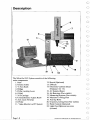
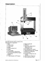

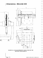
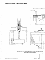
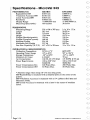


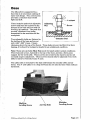
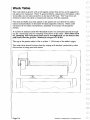
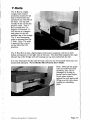
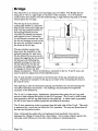
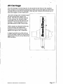
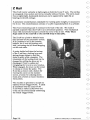
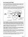
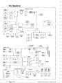
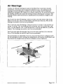
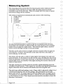
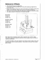

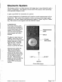
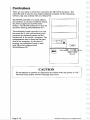
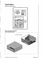
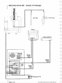
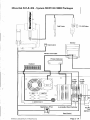


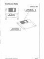
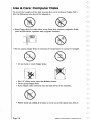
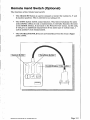
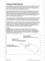
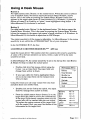
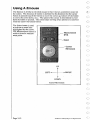
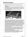
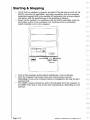
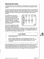
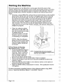
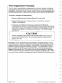
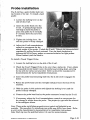
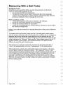
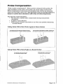
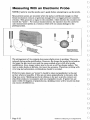
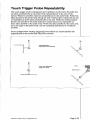
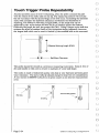
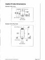
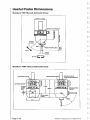


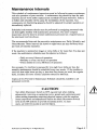
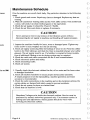
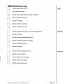
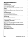
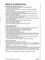
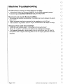
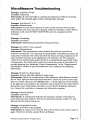
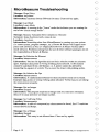
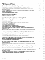
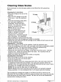
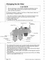
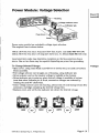
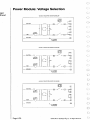
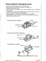


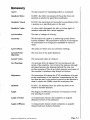
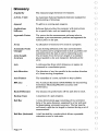

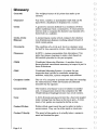
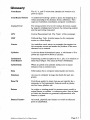
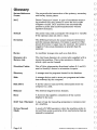
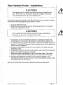
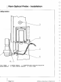
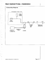
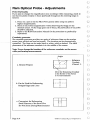

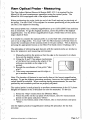


![Manual Audition 4 [By Dr.J.]](http://vs1.manualzilla.com/store/data/005935757_1-4addafd8884e379cc6f9c4cc1fe5fdba-150x150.png)