1
®
Advanced
Test Equipment Rentals
Jan. 2010
PART NO. Z1-004-702, IB019881
www.atecorp.com 800-404-ATEC (2832)
E stablished 1981
General
Description
1
Installation and
Preparation
2
Panel Operation
Basics
3
Performing Discharge
Testing
4
Performing Sequence
Testing
5
Using the Application
Software
6
Specifications
7
User’s Manual
Electrostatic Discharge Simulator
KES4022A
App
DANGER
This product generates high voltage!
• Improper operation can lead to serious accidents.
• Keep this manual close to the product so that the operator
can read it at anytime.
Thank you for purchasing the KES4022A Electrostatic
Discharge Simulator.
About this manual
About Operation Manual
The operation manual for the KES4022A is consisting of the
"User's Manual"(this manual) and the "Communication
Interface Manual".
User’s manual (this manual)
The User’s manual is intended for first-time users of this
product. It provides an overview of the product and notes on
usage. It also explains how to configure the product,
operate the product, perform maintenance on the product,
and so on.
The communication interface manual
The communication interface manual describes the content
of the commands.
The interface manual is provided in HTML format on the
supplied CD-ROM (a portion of the manual is in PDF
format). You can view it using Microsoft Internet Explorer
5.5 or later. You can view the PDF file using Adobe Reader
6.0 or later.
Operation manual has been prepared with the utmost care;
however, if you have any questions, or note any errors or
omissions, please contact Kikusui distributor/agent.
If the operation manual gets lost or soiled, a new copy can be
provided for a fee. In either case, please contact Kikusui
distributor/agent, and provide the “Kikusui Part No.” given on
the cover page.
Read this manual thoroughly to use the functions of the
product effectively. You can also review this manual when you
are confused about an operation or when a problem occurs.
After reading, always keep the manual nearby so that you may
refer to it as needed. When moving the product to another
location, be sure to bring the manual as well.
If you find any misplaced or missing pages in this manual, it
will be replaced.
Product firmware
manual covers
versions
that
this
This manual applies to products with firmware versions 1.0X.
When contacting us about the product, please provide us with:
The model (marked in the top section of the front panel)
The firmware version (see page 25)
The serial number (marked in the bottom section of the rear
panel)
How to read this manual
This manual is designed to be read from beginning to end. We
recommend that you read it thoroughly before using this
product for the first time.
Intended readers of this manual
Trademark acknowledgements
This manual is intended for users of the product or persons
teaching other users on how to operate the product.
Microsoft and Windows are registered trademarks of Microsoft
Corporation in the United States and/or other countries.
The manual assumes that the reader has knowledge about
electrical safety testing.
Other company names and product names used in this
manual are generally trademarks or registered trademarks of
the respective companies.
Copyrights
The contents of operation manual may not be reproduced, in
whole or in part, without the prior consent of the copyright
holder.
The specifications of this product and the contents of
operation manual are subject to change without prior notice.
© 2010 Kikusui Electronics Corporation
2
KES4022A
Notes to the supervisor
If the operators cannot understand the language used in this
manual, translate the manual into the appropriate language.
Make sure that the operators understand the information in
this manual before they operate this product.
Keep this manual close to the product so that the operators
can read it at anytime.
Dangerous operations
You will receive a potentially fatal electric shock if:
• You touch the tip of the discharge gun while the KES4022A
output is on.
• You touch the cup of the discharge gun while the
KES4022A output is on.
• You touch the EUT while the KES4022A output is on.
• You touch a component that is electrically connected to the
EUT immediately after the KES4022A output is stopped.
You may receive a potentially fatal electric shock if:
• You operate the KES4022A without grounding it.
• You go near a component that is electrically connected to
the EUT while the KES4022A output is on.
• You go near a component that is electrically connected to
the EUT immediately after the KES4022A output is shut
down.
Conditions that can shorten the service
life of the high-voltage switch
Safety Symbols
For the safe use and safe maintenance of this product, the
following symbols are used throughout operation manual and
on the product. Note the meaning of each of the symbols to
ensure safe use of the product. (Not all symbols may be
used.)
or
Indicates that a high voltage (over 1 000 V) is used here.
Touching the part causes a possibly fatal electric
shock. If physical contact is required by your work,
start work only after you make sure that no voltage is
output here.
DANGER
Indicates an imminently hazardous situation which, if
ignored, will result in death or serious injury.
WARNING
Indicates a potentially hazardous situation which, if
ignored, could result in death or serious injury.
CAUTION
Indicates a potentially hazardous situation which, if
ignored, may result in damage to the product and other
property.
Indicates a prohibited act.
Indicates a warning, caution, or danger. When
this symbol is marked on the product, see the
relevant section in this manual.
The high-voltage switch in the discharge gun that is used to
generate discharges wears out over time. The high-voltage
switch will wear out rapidly if you use the KES4022A:
Protective conductor terminal.
• With a test voltage that exceeds the IEC test level.
Chassis (frame) terminal.
• With the discharge interval set to less than 1 second.*1
• In conditions other than those specified for IEC or ISO
standard testing.
On (power supply).
• In combination with the optional C unit and discharge
resistor.
Off (power supply).
In position of a bi-stable push control
Out position of a bi-stable push control
*1. The mechanical life of the high-voltage switch is 1,000,000
operations. This calculates to about 14 hours of continuous
operation if testing is performed using contact discharge at
20 pulses/second.
KES4022A
3
Notations used in this manual
• The KES4022A Electrostatic Discharge Simulator is also
referred to as the KES4022A.
• The entire system that includes the main unit and the
discharge gun is referred to as the product or the
KES4022A.
• The discharge gun and the high-voltage cable are
collectively referred to as the discharge gun.
• The panel control unit (everything except for the discharge
gun) is referred to as the main unit.
• IEC 61000-4-2 Ed.2.0 2008-12 is referred to as the IEC
61000-4-2 standard.
• ISO 10605 Ed.2.0 2008-07 is referred to as the iSO 10605
standard.
• The following markings are used in this manual.
WARNING
Indicates a potentially hazardous situation which, if
ignored, could result in death or serious injury.
Safety Precautions
The following safety precautions must be observed to avoid
fire hazards, electric shock, accidents, and device failures.
Keep them in mind and make sure to observe them.
Using the product in a manner that is not specified in this
manual may impair the protection functions provided by the
product.
ration
Ope
al
Manu
Users
• This product must be used only by qualified personnel who
understand the contents of this operation manual.
• If an unqualified personnel is to use the product, be sure the
product is handled under the supervision of qualified
personnel (those who have electrical knowledge). This is to
prevent the possibility of personal injury.
• If you have a heart condition, if you are pregnant or believe
you may be pregnant, or if you use a pacemaker or other
medical device, do not use this product.
CAUTION
Indicates a potentially hazardous situation which, if
ignored, may result in damage to the product or other
property.
Purpose of use
• Never use the product for purposes other than the product’s
intended use.
Indicates information that you should know.
DESCRIPTION
Explanation of terminology or operation principle.
• This product is not designed or manufactured for general
home or consumer use.
Line
Voltage
Input power
See
Indicates reference to detailed information.
SHIFT+key name (marked in blue)
Indicates an operation that requires you to press a key
indicated in blue letters while holding down the SHIFT key.
• Use the product within the rated input line voltage range.
• For applying power, use the power cord provided. For
details, see the respective page in this manual.
• This product is an equipment of IEC Overvoltage Category
II (energy-consuming equipment supplied from the fixed
installation).
Cover
Some parts inside the product sare hazardous. Do not remove
the external cover.
G N L
Grounding
This product is IEC Safety Class I equipment (equipment with
a protective conductor terminal). To prevent electric shock, be
sure to connect the protective conductor terminal of the
product to electrical ground (safety ground).
4
KES4022A
Installation
• This product is designed for safe indoor use. Be sure to use
the product indoors.
• When installing this product, be sure to observe the
precautions regarding the installation location. For details,
see the respective pages in this manual.
Relocation
Discharge gun
• When the high-voltage indicator or DANGER indicator is
illuminated, do not bring your hand close to the discharge tip
or cup.
• Do not drop the discharge gun, CR unit, or discharge tips. If
any of these are dropped, contact your Kikusui agent or
distributor to arrange an inspection of the dropped
component.
• Turn off the POWER switch, and disconnect the cables
before relocating the product.
• When relocating the product, be sure to include the manual.
Che
ck?
Operation
• Before use, visually check for problems in the power cord,
discharge gun, and high-voltage cable. When checking for
these problems, remove the power cord plug from the
outlet.
• If you notice a malfunction or abnormality in the product,
stop using it immediately, and remove the power cord plug
from the outlet. Make sure the product is not used until it is
completely repaired.
• Do not disassemble or modify the product. If you need to
modify the product, contact your Kikusui distributor or agent.
Maintenance and inspection
• To prevent electric shock, be sure to unplug the product
before carrying out maintenance or inspection. Do not
remove the external cover.
• Check periodically that there are no tears or breaks in the
power cord.
• If the panel needs cleaning, gently wipe it using a soft cloth
with water-diluted neutral detergent. Do not use volatile
chemicals such as benzene or thinner.
• To maintain the performance and safety of the product, we
recommend periodic maintenance, inspection, cleaning,
and calibration.
Service
Kikusui service engineers will perform internal service of the
product. If the product needs adjustment or repairs, contact
your Kikusui distributor or agent.
KES4022A
5
Contents
About this manual 2
Notes to the supervisor 3
Dangerous operations 3
To Start Testing 48
To Pause and Redo Testing 52
Completion of Testing 52
Sequence
5 Performing
Testing
Conditions that can shorten the service life
of the high-voltage switch 3
Sequence Operation Procedure 54
Starting Sequence Operation 55
Creating a New Step 56
Editing a Step’s Testing Conditions 58
Copying a Step’s Testing Conditions 59
Moving a Step’s Position 60
Deleting Steps 60
Examples of How to Create Sequences 62
Starting Sequence Operation 66
Stopping Sequence Operation 68
Safety Symbols 3
Notations used in this manual 4
Safety Precautions 4
Contents6
Search by Topic7
Front panel8
Discharge gun10
1
2
General Description
Product Overview 12
Options 13
6
Application Software Overview 70
Installing the Application Software 71
Configuring RS232C 72
Starting the Application 73
Configuring Manual Operation 74
Configuring IEC Test Level operation 76
Configuring Step Operation 78
Configuring Sequence Operation 80
Configuring Communication Settings 82
Saving and Loading Test Conditions 83
Communication with the KES4022A 86
Installation and
Preparation
Checking the Package Contents 18
Precautions about the Installation Location 19
Precautions for Moving the Product 20
Preparing the Discharge Gun 21
Connecting the Power Cord 24
Turning the power on 25
Steps to Be Taken in an Emergency 26
3
Panel Operation
Basics
Selecting the Discharge Test 28
Selecting the Discharge Mode 29
Setting Test Voltages 30
Setting the Polarity 33
Setting the Number of Discharges 34
Setting the Discharge Interval 35
Setting the Discharge Points 36
Setting the Trigger Used to Start Testing 36
Configuring the Wait Feature 37
Specifying the CONFIG Settings 38
Other Settings 42
4
Using the Application
Software
7
Specifications
Appe A How Discharging Works 94
ndix B List of Default Settings 95
C Troubleshooting98
D Maintenance 99
E About Errors 104
INDEX105
Performing Discharge
Testing
Before Testing 46
Setting Test Conditions 47
Putting the KES4022A into standby 47
6
KES4022A
Search by Topic
Preparation
Setup
• What accessories are included in the
package?
➔“ Checking the Package Contents”
• How do I change the CR unit?
➔“ Checking and replacing the CR
unit”
p.21
• How do I replace the discharge tip?
➔“ Attaching the discharge tip”
p.22
• What are the different test types?
➔“ Selecting the Discharge Test”
p.28
• What are the voltages that are set for the ➔ “ Setting the IEC61000-4-2 test level (in
manual or IEC test level operation)”
different IEC test levels?
• How do I set the step voltage?
➔“ Specifying the CONFIG Settings”
➔“ Changing the Resolution”
• How do I change the resolution when
setting the test voltage or discharge count?
• What is the RS232C protocol that the
KES4022A uses?
➔“ Protocol”
• How do I reset the KES4022A to its factory ➔“ Initializing the KES4022A”
default settings?
Operation
p.31
➔“ Setting step operation test voltages” p.32
• What polarity switch patterns can I use in ➔“ Setting the Polarity”
automatic testing?
• How do I change the discharge counter
mode and gun trigger mode?
p.18
p.33
p.38
p.43
p.72
p.95
• How do I save the current test conditions ➔“ Storing test conditions to memory”
p.40
and use them later?
• When a test is redone, which step does it ➔“ Redoing a test”
restart from?
p.42
• How many times has the discharge gun's ➔ “ Displaying the number of times the highvoltage discharge switch has been used” p.43
high-voltage switch been used?
Maintenance
• What kind of displays appear during
sequence testing? What kind of buzzer
sounds at the end of a step?
➔“ Displayed information during
testing”
• How do I send the settings that I
configured using the application to the
KES4022A?
➔ “ Sending the test conditions that have
• How do I inspect the KES4022A before
testing?
➔“ Preliminary inspection”
been saved in the application to the
KES4022A”
• How should I clean the KES4022A and the ➔”“ Cleaning
discharge gun?
• How do I calibrate the KES4022A?
➔“ Calibration”
p.66
p.86
p.23
p.99
p.101
To solve problems
See “Troubleshooting” on page 98.
KES4022A
7
Front panel
Display
10 11 12
13
14
15
8
9
16
17
18
19
20 21 22
NO.
FIN
WAIT
RMT
kV
COUNT
POINT
2
DANGER
HIGH VOLTAGE
s
MODE
C
A
20
COUNT
RST CLEAR
NB00XXX-1
HIGH VOLTAGE
OUTPUT
±30kV MAX
TRIGGER
P
G
RESET
CONFIG
MODE
TRIGGER OPERATION
WAIT
IEC
STEP
SEQ
LOCAL
SELECT
NB00928-1
SET-V
EDIT
4
5
NB00XXX-1
ON
COARSE
/FINE
OFF
ENTER
SHIFT
3
ELECTROSTATIC
DISCHARGE SIMULATOR
RECALL
STORE
GOOD
NG
POLARITY
TOTAL COUNT
TEST
1
KES4022A
IEC TEST LEVEL
2
3
4
RECALL(MEMORY 1-4)
OPTION
POWER
RS232C
IEC61000-4-2 Ed.2.0 2008
6
7
1
29 30 31
23
32
24
25
26
33
34
27
28
35
TOTAL COUNT
36 37
No.
8
38
Name
Function
See
1
POWER switch
Turns the power on and off.
p.25
2
DANGER indicator
Illuminates when high-voltage power is being delivered or when
the KES4022A is in standby.
p.47
3
HIGH VOLTAGE OUTPUT
Delivers high voltage. The discharge gun’s high-voltage cable is
connected to this terminal. You cannot remove the discharge gun.
4
HIGH VOLTAGE ON switch
Turns high-voltage power output on.
p.47
5
HIGH VOLTAGE OFF switch
Shuts down high-voltage power output.
p.52
6
OPTION connector
Do not connect anything to this connector.
7
RS232C connector
RS232C interface.
p.72
8
NO. display
Displays the step number and other information.
p.72
9
Lower display
Displays the discharge points, number of discharges, discharge
interval, etc.
—
10
Upper display
Displays the test voltage, etc.
—
—
—
KES4022A
No.
Name
Function
See
11
FIN LED
Illuminates when a test finishes.
p.49
12
WAIT LED
Illuminates when the KES4022A is in the wait state.
p.49
13
RMT LED
Illuminates when the KES4022A is communicating with the PC.
p.82
14
kV
Illuminates when the upper display indicates the test voltage.
p.30
15
COUNT
Illuminates when the lower display indicates the number of
discharges.
p.34
16
POINT
Illuminates when the lower display indicates the number of
discharge points.
p.36
17
s
Illuminates when the lower display indicates the discharge interval.
p.35
18
MODE LED
The selected discharge mode illuminates: C for contact, A for air,
and 20 for 20 discharges/s.
p.29
19
TRIGGER LED
The selected trigger illuminates: P for TEST key and G for trigger
switch.
p.36
20
IEC LED
Illuminates when an IEC test level operation is selected.
p.28
21
STEP LED
Illuminates when the step operation is selected.
p.28
22
SEQ LED
Illuminates when the sequence operation is selected.
p.28
COUNT RST key
Resets the number of discharges.
p.42
RESET key
Resets tests.
p.42
MODE key
Switches the discharge mode between contact mode, air mode,
and 20 discharges/s mode.
p.29
WAIT key
Configures the wait feature.
p.37
TRIGGER key
Sets the trigger to the TEST key or trigger switch.
p.36
SET-V key
Sets the step operation test voltage.
p.32
SHIFT key
Activates the features indicated by blue letters below the keys
p.4
RECALL key
Recalls settings from panel memory
p.41
GOOD key
No functionality.
STORE key
Saves settings to panel memory.
NG key
No functionality.
CLEAR key
Resets errors.
p.104
CONFIG key
For configuring the KES4022A.
p.38
30
LOCAL key
Switches local mode.
—
31
SELECT key
Switches the item that you will configure between the voltage,
number of discharges, discharge points, or discharge interval.
—
32
Rotary knob
Changes the value.
—
COARSE/FINE key
Switches the resolution of the test voltage and number of
discharges.
ENTER key
Confirms the sequence operation settings.
OPERATION key
Selects the test method.
EDIT key
For setting sequence operation steps.
POLARITY key
Switches the set voltage polarity.
p.33
TOTAL COUNT key
Switches the displaying the number of times the high-voltage
discharge switch has been used.
p.43
36
TEST LED
Illuminates during testing.
p.49
37
TEST key
Starts and stops testing.
p.48
IEC TEST LEVEL key
Selects the IEC61000-4-2 standard test level from 1 to 4.
p.31
RECALL (MANUAL STEP) key
Recalls settings from panel memory using the direct recall feature.
p.41
23
24
25
26
27
28
29
33
34
35
38
KES4022A
—
p.40
—
p.43
—
p.28
—
9
Discharge gun
1
2
3
4
5
6
7
8
9
10
No.
11
Name
Function
See
1
Protective cap
Protective cap for the contact discharge tip.
p.22
2
Discharge tip
Emits electrostatic discharges to the EUT.
p.22
3
Cup
Forms the discharge current waveform.
4
High-voltage indicator
Illuminates when high-voltage power is being delivered or when the
KES4022A is in standby.
p.47
5
CR unit
A unit that is inserted into the discharge gun.
p.21
6
CR unit cap
Holds the CR unit in place.
p.21
7
Discharge gun stand
attachment
Used when the discharge gun is mounted on the optional discharge
gun stand.
8
Trigger
For starting and stopping testing by using the discharge gun.
9
Grip
For holding the discharge gun.
10
Discharge return cable
Functions as a line for the discharge current to return through.
11
High-voltage cable
Composite cable that consists of a shielded high-voltage wire and
signal wires.
—
—
p.48
—
p.23
—
Rear panel
1
2
No.
10
3
4
Name
Function
1
Cord holder
For winding the power cord for storage (one in each corner).
2
AC INPUT connector
AC inlet.
3
Protective conductor terminal For earth grounding the KES4022A.
4
Serial number
—
See
—
p.24
p.24
—
KES4022A
1
General Description
This chapter gives an overview of the
KES4022A and the options that are
available for it.
Product Overview
Electrostatic discharge is a commonly occurring phenomenon. An arc current or
electromagnetic wave caused by electrostatic discharge entering an electronic circuit can
cause errors and failures. This is a serious problem today, because the vast majority of
electric and electronic devices use semiconductors. Standards that define electrostatic
discharge immunity and that specify methods for testing immunity have been established to
deal with this problem.
The KES4022A Electrostatic Discharge Simulator is used to perform immunity testing on
electric and electronic devices subject to electrostatic discharges. It can perform testing that
conforms to the IEC61000-4-2 standard.
Features
● Testing based on the IEC 61000-4-2 standard
The KES4022A complies with IEC 61000-4-2 Ed.2.0 2008-12.
IEC/ISO-compliant model conform to the ISO 10605 Ed. 2.0 2008-07 standard for the
electrostatic discharge testing of automotive electronics.
● Maximum test voltage: ±30 kV
The maximum test voltage is ±30 kV. This allows you to perform preliminary tests and
allowance tests.
The KES4022A can perform contact discharge and air discharge testing.
● Easy operation
The panel is designed for easy operation. You can select test levels from the panel.
● Memory features
Twenty sets of test conditions can be stored separately for manual, IEC test level, step,
and sequence modes.
● Step operation
You can set step voltages and perform testing by changing the test voltage by small
amounts.
● Sequence operation
You can perform testing by combining various test conditions. You can easily configure
the test conditions from a PC through the RS232C interface.
● Multi-point discharges
Because you can set multiple discharge points (up to 10 points), you can save time in
testing.
● Configuration of test conditions using a PC
You can use the application software (that is stored in KES4022A_SAMPLE_APPLICATION_
SOFTWARE.xls) to set test conditions and transmit test conditions to the KES4022A through
RS232C. You can also edit the test conditions set from the panel.
12
KES4022A
Options
For information about options, contact your Kikusui agent or distributor.
CR units and discharge tips for ISO10605:2001
General Description
1
We offer discharge tips and CR units. A CR unit consist of an energy storage capacitor and a
discharge resistor.
CR units
Calibration is necessary if you want to change the CR unit that is included as standard, and
perform testing based on standards such as IEC 61000-4-2 and ISO 10605. To have your
KES4022A calibrated, contact your Kikusui distributor or agent.
CR32-KES
330 pF/330 Ω
CR33-KES
150 pF/2 kΩ
CR34-KES
330 pF/2 kΩ
Discharge tips
AT32-KES
Air discharge tip (2 kΩ)
CT32-KES
Contact discharge tip (2 kΩ)
ST31-KES
Sphere discharge tip (330 Ω)
ST32-KES
Sphere discharge tip (2 kΩ)
C units and discharge resistors
IEC61000-4-2 specifies the combination of a 150-pF energy storage capacitor and a 330-Ω
discharge resistor. These options are used to test other combinations.
C unit
Discharge resistor
EC21-KES: 150 pF
DR21-KES: 330 Ω
DR28-KES: 1 kΩ
EC22-KES: 100 pF
DR22-KES: 100 Ω
DR29-KES: 1.5 kΩ
EC23-KES: 200 pF
DR23-KES: 150 Ω
DR30-KES: 2 kΩ
EC24-KES: 250 pF
DR24-KES: 200 Ω
DR31-KES: 5 kΩ
EC25-KES: 300 pF
DR25-KES: 300 Ω
DR32-KES: 10 kΩ
EC26-KES: 330 pF
DR26-KES: 400 Ω
DR33-KES: 10 Ω
EC27-KES: 400 pF
DR27-KES: 500 Ω
Discharge resistance
C unit
—
EC28-KES: 500 pF
KES4022A
13
Options
Electrostatic discharge immunity testing environment
IEC61000-4-2 defines electrostatic discharge immunity testing apparatus based on the
characteristics of the EUT. These options can be combined to create an apparatus for
performing electrostatic discharge immunity testing that is appropriate for the EUT.
Vertical coupling plane
Horizontal coupling plane
Tabletop equipment
Insulation sheet
Ground wire
Resistance cable
Ground reference plane
Test table
Resistance cable
Vertical coupling plane
Floor-standing
equipment
EUT
Resistance cable
Ground wire
Ground reference plane
Insulation pallet
Ground reference plate (GP21-KES)
Three aluminum plates are joined together to create the ground reference plane whose
dimensions are 1800 mm × 2700 mm × 1.6 mm. The size of each aluminum plate is 1800
mm × 900 mm.
14
KES4022A
Options
The horizontal coupling plane measures 1600 mm × 800 mm and is a metal plate with the
same thickness and material as the ground reference plane.
Vertical coupling plane (VC21-KES or VC22-KES)
The vertical coupling plane is used to perform indirect discharge testing. The vertical coupling
plane measures 500 mm × 500 mm and is a metal plate with the same thickness and material
as the ground reference plane.
VC21-KES
Tabletop type
VC22-KES
Floor-standing type
1
General Description
Horizontal coupling plane (ZC21-KES)
Resistance cable (CL21-KES)
This cable is used to connect the horizontal or vertical coupling plane to the ground reference
plane. A 470-kΩ resistor is attached to each end.
Insulation sheet (IS21-KES)
This 0.5-mm-thick sheet is used to electrically isolate the horizontal coupling plane from the
EUT.
Testing table (TT21-KES)
This table is used to test EUTs that are designed to be used on a tabletop. It is a wooden
table that is 800 mm in height whose tabletop measures 1600 mm × 800 mm.
Insulation pallet (IP21-KES)
This 10-cm-thick pallet is placed on the ground reference plane to insulate the EUT from the
ground reference plane.
Discharge gun stand (GS21-KES)
This stand is used to hold the discharge gun.
Dimensions: 402 mm × 200 φ mm
Weight: Approx. 3 kg.
KES4022A
15
Options
16
KES4022A
2
Installation and Preparation
This chapter describes how to unpack and
prepare this product before you use it.
Checking the Package Contents
When you receive the product, check that all accessories are included and that the
accessories have not been damaged during transportation.
If any of the accessories are damaged or missing, contact your Kikusui agent or distributor.
We recommend that you keep all packing materials, in case the product needs to be
transported at a later date.
or
Rated voltage: 125 Vac
PLUG: NEMA5-15
[85-AA-0003]
Power cord (1 pc.)
or
Rated voltage: 250 Vac
PLUG: CEE7/7
[85-AA-0005]
Rated voltage: 250 Vac
PLUG: GB1002
[85-10-0790]
The power cord that is provided varies depending on the
destination for the product at the factory-shipment.
Model display
Model display
Contact discharge tip (330 Ω)
(with a protective cap)
[CT31-KES]
Air discharge tip (330 Ω)
[AT31-KES]
CD-ROM (1 pc.)
[SA-6034]
Operation manual (1 copy)
[Z1-004-702]
IEC/ISO-compliant model only
Model display
Air discharge tip (2 kΩ)
[AT32-KES]
Model display
Contact discharge tip
(with a protective cap)
[CT32-KES]
Model display
Sphere discharge tip
(330 Ω) [ST31-KES]
Model display
Sphere discharge tip
(2 kΩ) [ST32-KES]
Model
display
CR unit
(330 pF/330 Ω)
[CR32-KES]
Model
display
CR unit
(150 pF/2 kΩ)
[CR33-KES]
Model
display
CR unit
(330 pF/2 kΩ)
[CR34-KES]
The CR31-KES unit (that consists of a 150-pF energy storage capacitor and a 330-Ω
discharge resistor) is built into the discharge gun.
18
KES4022A
Precautions about the Installation Location
You must observe the following precautions when installing the product.
To prevent the possibility of explosion or fire, do not use the product near alcohol, thinner,
or other combustible materials, or in an atmosphere containing such vapors.
● Avoid locations where the product is exposed to high temperature or direct
sunlight.
Do not install the product near a heater or in areas subject to drastic temperature
changes.
Operating temperature range:
+10 °C to +40 °C (+50 °F to +104 °F)
Storage temperature range:
-5 °C to +70 °C (+23 °F to +158 °F)
● Avoid humid environments.
Do not install the product in high-humidity locations such as near a boiler, humidifier, or
water supply.
Operating humidity range:
10 %rh to 80 %rh (no condensation)
Storage humidity range:
10 %rh to 80 %rh (no condensation)
2
Installation and Preparation
● Do not use the product in a flammable atmosphere.
Condensation may form even within the operating humidity range. If this happens, do not
use the product until the condensation dries up completely.
● Use the product indoors at up to 1300 m above sea level.
This product is designed for safe indoor use. The operating altitude limit is 1300 m above
sea level.
● Provide adequate space around the power cord plug.
Do not insert the power cord plug into an outlet that is not easily accessible. Do not place
objects near the power cord plug that would make it difficult to access.
● Do not install the product in a corrosive atmosphere.
Do not install the product in a corrosive atmosphere or in environments containing sulfuric
acid mist, etc. This may cause corrosion of various conductors or reduce the quality of the
connector contacts inside the product, and this could lead to malfunction, failure, and
possibly fire.
● Do not install the product in a dusty location.
Dust accumulation can lead to electric shock or fire.
● Do not use the product in a poorly ventilated location.
Provide adequate space around the product for air to circulate around it.
● Do not place objects on top of the product.
Placing heavy objects on top of the product may cause malfunction.
● Do not install the product on an inclined surface or in a location subject to
vibrations.
The product may fall or tip over and cause damage and injury.
● Do not use the product in a location subject to strong magnetic or electric fields or
in a location where the input power supply signal contains large amounts of
distortion or noise.
Doing so may cause the product to malfunction.
KES4022A
19
Precautions for Moving the Product
● Do not use the product near medical, electronic, or communication devices other
than the EUT.
This product emits strong electromagnetic noise. We recommend that you use the
product in a shielded room. Keep it sufficiently away from medical, electrical, electronic,
and communication devices that may be adversely affected by electromagnetic noise.
● Do not place objects near the product that will injure the operator if the operator
bumps into them.
If the operator receives an electric shock by mistake, the operator may react by abruptly
pulling his or her hand or by jumping back. In addition to direct injuries caused by electric
shock, the operator may suffer secondary injuries from bumping into objects or from
falling over when the operator reacts to the shock. Perform testing in a place with
sufficient space.
● Do not perform testing if a dangerous condition would result when the EUT power
supply shorts.
The power supply may short-circuit if the EUT breaks. Take measures so that a
dangerous condition will not result even if a short circuit occurs. We recommend that you
use an isolation transformer with the AC power supply used for testing to separate it from
other power supply systems.
● Be sure to adhere to the testing environment that the standard specifies.
The standard specifies various test conditions such as the size of the ground reference
plane, the distance from walls, the use of the horizontal coupling plane, and the use of the
vertical coupling plane. For details on the testing environment, see the respective
standard.
Precautions for Moving the Product
When moving or transporting the product to the installation location, be sure to:
● Turn the POWER switch off.
Moving the product with the POWER switch turned on may cause electric shock or
damage to the product.
● Disconnect all wiring and the discharge tip.
Moving the product with the cables connected may cause wires to break or injuries due to
the product falling over.
● Hold the product with both hands while making sure that the discharge gun does
not fall.
You cannot remove the discharge gun from the main unit.
● Use the original packing materials (when transporting the product).
Otherwise, damage may result from vibrations or from the product falling during
transportation.
● Include this manual.
20
KES4022A
Preparing the Discharge Gun
To avoid electric shock, wait at least 1 minute after turning the POWER switch off
before checking the CR unit, removing the discharge tip, and connecting the
discharge return cable.
Do not drop the discharge gun. If you drop it, do not use it.
To maintain good insulation characteristics, be sure to clean the red discharge gun cup before
testing.
See p. 99
CR units and discharge tips can distinguish discharge resistor value with the color of the
model display label.
330 Ω discharge resistors: Purple
2 kΩ discharge resistors: Green
2
Installation and Preparation
WARNING
Checking and replacing the CR unit
The CR unit consists of an energy storage capacitor that generates electrostatic discharge
and a discharge resistor that limits the discharge current.
WARNING
To avoid electric shock, turn the POWER switch off before checking or replacing the CR
unit. A buzzer will sound if you remove the CR unit cap while the POWER switch is on.
Do not remove the CR unit's internal discharge resistor. If you do so, the generated
waveform is no longer guaranteed.
CR unit cap
CR unit
Label
MODEL CR31 - KES
I
CR UNIT 150pF 330 O
I
KIKUSUI ELECTRONICS CORP.
MADE IN JAPAN
Resistance and capacitance
KES4022A
1
Check that the POWER switch is off.
If it is on, turn it off, and wait at least 1 minute. The KES4022A will naturally discharge
down to a safe voltage.
2
3
Remove the CR unit cap, and remove the CR unit from the discharge gun.
4
5
Put the CR unit back into the discharge gun.
Check the capacitor and discharge resistor values (150 pF and 330 Ω for a
standard setting).
Securely attach the CR unit cap.
21
Preparing the Discharge Gun
Attaching the discharge tip
Discharge tips are metallic electrodes for applying electrostatic discharges to the EUT. There
are three types of discharge tips: contact discharge tip, air discharge tip, and sphere
discharge tip. Attach the appropriate tip according to the test objective.
Model
display
Air discharge tip
Model
display
Contact discharge tip
Model
display
Sphere discharge tip
(IEC/ISO-compliant
model only)
The contact discharge tip is sharp. Put the protective cap on it when it is not in use. The
protective cap is made of vinyl. If you apply strong force to the cap when it is on the tip, the tip
may pierce through the cap.
CAUTION
Dropping the discharge tip or applying strong shock to it may break the tip or cause
waveforms to be distorted.
Attach
Detach
22
1
Check that the POWER switch is off.
If it is on, turn it off, and wait at least 1 minute. The KES4022A will naturally discharge
down to a safe voltage.
2
Securely attach the discharge tip to the discharge gun.
KES4022A
Preparing the Discharge Gun
Connecting the discharge return cable
WARNING
To avoid electric shock, securely connect the discharge return cable to the ground
reference plane.
2
Installation and Preparation
The discharge return cable is a line for the discharge current to return through. Do not use it
in a wound or bundled condition.
Ground reference plane
Example of a connection
Discharge return cable
1
Check that the POWER switch is off.
If it is on, turn it off, and wait at least 1 minute. The KES4022A will naturally discharge
down to a safe voltage.
2
Securely connect the discharge return cable to the ground reference plane.
Preliminary inspection
Be sure to perform a preliminary inspection to prevent electric shock and to maintain the
KES4022A’s long-term performance.
See p. 99
KES4022A
1
Check that the insulation of the high-voltage cable and discharge return cable is
clean and not broken.
2
Check that the cable insulation at the HIGH VOLTAGE OUTPUT terminal and at
the root of the discharge gun is not misaligned or loose.
3
Check that the discharge gun does not have cracks and that the screws are
fastened securely.
4
5
Check that the CR unit cap is securely fastened.
Check that the red discharge gun cup is not dirty.
To maintain good insulation characteristics, clean the cup if it is dirty.
23
Connecting the Power Cord
This product falls under IEC Overvoltage Category II (energy-consuming equipment supplied
from the fixed installation).
WARNING
To avoid electric shock, observe the following precautions.
• This product is IEC Safety Class I equipment (equipment with a protective conductor
terminal). Be sure to earth ground the product to prevent electric shock.
• Connect the protective conductor terminal to earth ground.
• Use the supplied power cord to connect to an AC power line.
If the supplied power cord cannot be used because the rated voltage or the plug shape is
incompatible, have a qualified engineer replace it with an appropriate power cord that is 3
m or less in length. If obtaining an appropriate power cord is difficult, consult your Kikusui
agent or distributor.
• A power cord with a plug can be used to disconnect the product from the AC line in an
emergency. Connect the plug to an easily accessible power outlet so that the plug can be
removed from the outlet at any time. Be sure to provide adequate clearance around the
power outlet.
• Do not use the supplied power cord for other devices.
To a properly grounded outlet
1
2
Check that the POWER switch is off.
3
4
Connect the power cord to the rear-panel AC INPUT.
Check whether or not the AC power line is compatible with the input rating of the
product.
The product can receive a nominal line voltage in the range of 100 Vac to 240 Vac at
50 Hz or 60 Hz.
Connect the power cord plug to an outlet with a ground terminal.
You can also ground the KES4022A through the protective conductor terminal. Have a
qualified engineer construct a proper cable and connect it. Use appropriate tools and
securely connect the cable.
Proper ground
24
KES4022A
Turning the power on
Turning the POWER switch on
1
2
3
Perform preliminary inspection on the discharge gun.
4
Check the firmware version on the screen.
After all LEDs on the front panel illuminate, the upper display shows the model name,
and the lower display shows the firmware version for several seconds.
Check that the power cord is connected properly.
Press the front-panel POWER switch so that it is on (the I position).
If you notice strange sounds, unusual odors, fire, or smoke around or from inside the
KES4022A, remove the power cord plug from the outlet.
Installation and Preparation
See p. 23
2
Model (KES4022A)
Firmware version (1.00)
Example of firmware version 1.00
When you turn the POWER switch on for the first time after purchase, the KES4022A starts
with its factory default settings.
You can use CONFIG setting 7 (the panel settings at power-on) to specify the panel settings
that will be in effect when the POWER switch is turned on.
See p. 38
Turning the POWER switch off
CAUTION
To avoid breakdown, allow at least 10 seconds to turn the KES4022A’s POWER switch on
after it has been turned off, or off after it has been turned on. Do not needlessly turn the
switch on and off repeatedly.
1
Check that the DANGER indicator is not illuminated.
If it is, press the HIGH VOLTAGE OFF switch to stop the output.
2
3
4
Connect the discharge tip to GND to discharge the remaining electric charge.
Press the front-panel POWER switch so that it is off (the O position).
Clean the test area so that it is free of obstacles.
Except for in an emergency, do not turn the POWER switch off while the output is on. The
KES4022A protective features may not activate. If you turn the POWER switch off while the
output is on in an emergency, be sure to eliminate the dangerous condition, and do not use
the KES4022A until safety has been assured.
KES4022A
25
Steps to Be Taken in an Emergency
If an emergency situation such as electric shock or EUT breakdown occurs due to problems
with the KES4022A or the EUT, turn the POWER switch off immediately, and remove the
power cord plug from the outlet. The KES4022A high-voltage power supply will be shut down,
and discharging will stop.
Record the KES4022A conditions, and contact your Kikusui agent or distributor.
■ Emergency and abnormal situations
•
Electric shock
•
EUT breakdown
•
Operation errors in devices other than the EUT
•
Constant ringing of the KES4022A buzzer
•
Abnormal set voltage
•
Abnormal sounds inside the discharge gun or the main unit
■ Turning the power on after an emergency situation occurred in a device
other than this KES4022A
1
2
3
26
Eliminate the dangerous condition.
Make sure that everything is safe.
Turn the POWER switch on.
KES4022A
3
Panel Operation Basics
This chapter describes how to set basic
items.
WARNING
To avoid electric shock, observe the following precautions.
• By design, the KES4022A has exposed parts that generate high
voltages that are greater than or equal to 30 kV. When the
KES4022A is generating high voltage, do not bring your hands
close to such parts.
• During or after testing, the EUT and metal parts within the
testing environment may also be charged with high voltage. Do
not touch anything other than the ground reference plane
during testing. Metal parts that are not electrically connected to
the reference plane remain charged even after testing has been
completed. Do not touch the parts until you discharge the
electrical charge.
• Discharge only to the EUT, vertical coupling plane, horizontal
coupling plane, or ground reference plane.
• If you notice anything abnormal about the KES4022A, turn the
POWER switch off, and remove the power cord plug from the
outlet. After correcting the problem, check carefully to make
sure that everything is safe, and then turn the power on.
Selecting the Discharge Test
There are two types of discharge test modes: manual and auto. There is one manual
operation. There are three auto operations: IEC test level, step, and sequence. Each time
you press OPERATION, the selected operation switches.
Manual operation
Auto operation
Tests using the specified
test conditions
Test consisting of
several test condition
combinations
Single operation (all off)
The selected operation
illuminates.
IEC test level operation (IEC)
Step operation (STEP)
Sequence operation (SEQ)
OPERATION key
Manual operation (single operation)(
)
When testing is performed, the test conditions remain the same unless you change them. If
the IEC LED, STEP LED, and SEQ LED are all off, single operation is selected.
You can also select the IEC61000-4-2 test level.
Auto operation
An auto operation test uses several sets of test conditions. Each set of test conditions is
tested in order.
■ IEC test level operation (
)
Auto operation in which you set the IEC test levels and polarities.
Testing is performed in order from the lowest IEC61000-4-2 test level to the selected test
level. The IEC LED illuminates.
■ Step operation (
)
Auto operation in which you set the step voltage and polarities.
Testing is performed in order according to the set starting, ending, and step voltages. The
STEP LED illuminates.
If you select step operation, the upper display shows “– – – – –”.
■ Sequence operation (
)
Auto operation in which you set appropriate test conditions.
Testing is performed in order from step 1 using to the set test conditions. The SEQ LED
illuminates.
You set sequence operation test conditions after switching to the sequence editing screen
by pressing EDIT (SHIFT+OPERATION). For details, see the “Performing Sequence Testing”
in chapter 5.
28
KES4022A
Selecting the Discharge Mode
The IEC61000-4-2 standard defines Contact Discharge and Air Discharge. For more details,
see the IEC61000-4-2 standard.
■ Contact Discharge mode
Contact discharge can be divided into direct discharge and indirect discharge.
In indirect discharge, you discharge to the vertical or horizontal coupling plane that is
installed near the EUT.
■ Air Discharge mode
In air discharge, you hold the discharge gun grip and bring the air discharge tip closer to the
EUT. Air discharge takes place in this process.
Selecting the discharge mode
Select which discharge mode you will use for testing.
3
Panel Operation Basics
In direct discharge, you touch the EUT with the discharge tip.
In addition to the Contact Discharge and Air Discharge modes, the KES4022A has a 20
discharges/s Contact Discharge mode (with a discharge interval of 0.05 s) that is useful in
preliminary testing.
The discharge mode switches in order each time you press MODE. The LED corresponding
to the selected discharge mode illuminates.
• C: Contact Discharge
• A: Air Discharge
• 20: 20 discharges/s Contact Discharge
Example when C (contact discharge) is selected
The selected mode
illuminates.
If the EUT has insulation coating on it, perform air discharge testing.
KES4022A
29
Setting Test Voltages
Setting the voltage (in manual or sequence operation)
Carry out the procedure below to set the test voltage.
On
Example when 2.00 kV is set
Set the voltage using the rotary knob
Press to change the polarity
See p. 33
30
1
Press SELECT key to turn the kV LED on.
Press SELECT key repeatedly until the kV LED turns on.
2
Turn the rotary knob to set the test voltage (in the range of 0.00 kV to 30.50 kV in
manual operation or 0.01 kV to 30.50 kV in sequence operation).
3
To change the test voltage polarity, press POLARITY key.
The polarity switches each time you press POLARITY.
KES4022A
Setting Test Voltages
Setting the IEC61000-4-2 test level
(in manual or IEC test level operation)
Press IEC TEST LEVEL1, 2, 3, or 4 to set the IEC61000-4-2 test level voltage. The selected
key illuminates.
The test voltage varies depending on the discharge mode.
Example when IEC test level 2 is selected
The key that you press illuminates
Test level
C or 20: Contact
Discharge mode
A: Air Discharge mode
LEVEL 1
2.0 kV
2.0 kV
LEVEL 2
4.0 kV
4.0 kV
LEVEL 3
6.0 kV
8.0 kV
LEVEL 4
8.0 kV
15.0 kV
Panel Operation Basics
3
■ Manual operation
Testing is performed only at the selected test level. If you change the test voltage, the key
turns off. The test voltage polarity switches each time you press POLARITY key.
■ IEC test level operation
See p. 33
KES4022A
Testing is performed in order from the lowest level to the selected level.
Set the test voltage polarity using the POLARITY key after setting the voltage.
31
Setting Test Voltages
Setting step operation test voltages
See p. 33
You can set the step operation start, stop, and step voltages.To test using decreasing steps,
set the stop voltage lower than the start voltage.
Set the test voltage polarity using the POLARITY key after setting the voltage.
Setting step operation voltages
If a step voltage exceeds the stop voltage, the stop voltage is used. For example, if you set
the start voltage to 0.5 kV, the stop voltage to 1 kV, and the step voltage to 0.45 kV, the
KES4022A tests 0.5 kV and 0.95 kV. The next voltage would be 1.4 kV, but the KES4022A
tests the stop voltage of 1 kV and stops the test.
Example when the starting voltage is 2.00 kV
Lower display
Set the start
voltage
On
Set the stop voltage
On
Blinking
Set the step voltage
Set the voltage using
the rotary knob
SELECT key
You can press IEC TEST LEVEL1, 2, 3, or 4 to set an IEC61000-4-2 test level voltage. When
you set the start or end voltage, the selected key illuminates. If you change the test voltage,
the key turns off.
32
1
Check that the STEP LED is turned on.
If it is not, press OPERATION key to turn the STEP LED on so that step operation is
selected. If you do not select step operation, you cannot set the step operation
voltages.
2
Press SET-V (SHIFT+TRIGGER) key to switch to the start voltage setup screen.
The lower display shows “StArt.”
3
4
Turn the rotary knob to set the start voltage in the range of 0.01 kV to 30.50 kV.
5
Turn the rotary knob to set the stop voltage in the range of 0.01 kV to 30.50 kV.
To test using decreasing steps, set the stop voltage lower than the start voltage.
6
Press SELECT key to switch to the step voltage setup screen.
The lower display shows “SteP.”
7
8
Turn the rotary knob to set the step voltage in the range of 0.01 kV to 30.50 kV.
Press SELECT key to switch to the stop voltage setup screen.
The lower display shows “StoP.”
Press SET-V (SHIFT+TRIGGER) key to close the step operation voltage setup
screen.
The upper display shows “- - - - -”, and the settings are confirmed.
KES4022A
Setting the Polarity
Press POLARITY key to select the output voltage polarity.
Manual operation or sequence operation
The output voltage polarity switches each time you press POLARITY key. When negative is
selected, a minus sign appears at the left of the upper display.
3
Panel Operation Basics
Example when -2.00 kV is set
The polarity changes each
time you press this key
IEC test level operation or step operation
Example when Pos is selected
Lower display
PoS
nEG
P-n
n-P
The polarity changes each
time you press this key
PA-nA
nA-PA
POLARITY key
In the IEC test level and step operations, you can configure the KES4022A to switch the
polarity for each step, to test all steps using positive voltages and then all steps using
negative voltages, or to test all steps using negative voltages and then all steps using positive
voltages. Each time you press POLARITY key, the setting changes in order as shown below.
The lower display shows the selected setting.
KES4022A
PoS
Test only positive voltages
nEG
Test only negative voltages
P-n
Start with a positive voltage and switch the polarity for each step
n-P
Start with a negative voltage and switch the polarity for each step
PAnA
Test all steps using positive voltages and then all steps using negative
voltages
nAPA
Test all steps using negative voltages and then all steps using positive
voltages
33
Setting the Number of Discharges
A minus sign appears at the left of the upper display when nEG is selected during an IEC test
level operation or when you are setting test conditions for step operation. When you have
selected P-n, n-P, PA-nA, or nA-PA, a minus sign blinks at the left of the upper display. A plus
sign does not appear when PoS is selected.
The following figure illustrates how the polarity changes for different settings in an IEC test
level operation.
PoS
nEG
Start
Start
LEVEL1 +
LEVEL1 −
LEVEL2 +
LEVEL2 −
End
End
P-n
n-P
PA-nA
nA-PA
Start
Start
Start
Start
LEVEL1 +
LEVEL1 −
LEVEL1 +
LEVEL1 −
LEVEL1 −
LEVEL1 +
LEVEL2 +
LEVEL2 −
LEVEL2
End +
LEVEL2 −
LEVEL1 −
LEVEL1 +
LEVEL2 −
LEVEL2 +
LEVEL2 −
LEVEL2 +
End
End
End
End
Test conditions:
IEC test level operation
Test voltage: Level 2
Setting the Number of Discharges
Set how many times the KES4022A will discharge at each discharge point or step.
Electrostatic discharge immunity testing places electrical stress on the EUT. Set an
appropriate number of discharges.
In the IEC61000-4-2 standard, the minimum number of discharges for each point is 10.
In manual operation, you can specify infinity. If you specify infinite testing, testing continues
until you pause it or until you press HIGH VOLTAGE OFF switch.
34
KES4022A
Setting the Discharge Interval
Example when the number of discharges is set to 10
On
1
Check that the DANGER indicator is off.
If not, press HIGH VOLTAGE OFF switch.
2
Press SELECT to turn the COUNT LED on.
Press SELECT key repeatedly until the COUNT LED turns on.
3
Turn the rotary knob to set the number of discharges to a value from 1 to 99999
or to “-----.”
“-----” corresponds to infinite (available only in manual operation). To select “-----,” turn
the rotary knob fully counterclockwise.
Press COARSE/FINE key to change the resolution.
See p. 43
Panel Operation Basics
3
Set the discharge count
using the rotary knob
Setting the Discharge Interval
Set the discharge interval.
The discharge interval is 1 second in the IEC61000-4-2 standard.
Example when the discharge interval is set to 1.0 s
On
Set the discharge interval
using the rotary knob
KES4022A
1
Check that the DANGER indicator is off.
If not, press HIGH VOLTAGE OFF switch.
2
Press SELECT key to turn the s LED on.
Press SELECT key repeatedly until the s LED turns on.
3
Turn the rotary knob to set the discharge interval in the range of 0.1 s to 99.9 s.
35
Setting the Discharge Points
Set how many times to repeat the discharges using the same test conditions. This option is
valid when auto operation is selected.
See p. 37
This option is useful for discharging to multiple locations.
When you specify multiple discharge points, we recommend that you perform testing with the
wait feature turned on.
Example when the number of discharge points is 3
On
Set the discharge points
using the rotary knob
1
Check that the DANGER indicator is off.
If not, press HIGH VOLTAGE OFF switch.
2
Press SELECT key to turn the POINT LED on.
Press SELECT key repeatedly until the POINT LED turns on.
3
Turn the rotary knob to set the discharge points in the range of 1 to 10.
Setting the Trigger Used to Start Testing
Select whether to start testing by using the discharge gun trigger or by using the front-panel
TEST key. The front-panel TEST key is used when the discharge gun is mounted on the
optional discharge gun stand.
The trigger mode switches each time you press TRIGGER key. The selected trigger LED
illuminates.
• P (PANEL): Start the test by using the front-panel TEST key.
• G (GUN): Start the test by using the discharge gun trigger.
Example when the trigger is set to discharge gun
The selected trigger
illuminates.
See p. 38
36
If you set the trigger mode to GUN, you can set how the gun trigger will operate.
KES4022A
Configuring the Wait Feature
If you enable the wait feature, the KES4022A pauses testing at each discharge point and
step. Before the next point or step is tested, another trigger is required. If the wait feature is
off, the testing of the next point or step starts after approximately 3 seconds.
This option is valid when auto operation is selected. It is invalid when air discharge mode is
selected.
Example when the wait feature is on
On
Blinking
Set the wait feature using the rotary knob
KES4022A
1
Press WAIT (SHIFT+MODE) key.
The WAIT LED turns on, and the WAIT (SHIFT+MODE) key blinks.
2
Turn the rotary knob to enable or disable the wait feature.
Turn the knob to the right to enable (on) the feature or to the left to disable (oFF) it.
3
Press WAIT (SHIFT+MODE) key again.
The wait feature is enabled.
3
Panel Operation Basics
The wait feature is useful when you want to check the EUT condition at each discharge point
or step or when multiple discharge points are specified.
37
Specifying the CONFIG Settings
This section explains how to set the KES4022A operating conditions.
SELECT key
Example when the discharge gun
trigger mode is Push
1. Set the RS232C baud rate
2. Buzzer volume
(when a test ends)
3. Buzzer volume
(when an alarm occurs)
Blinking
Change the setting
using the rotary knob
4. Display brightness
5. Discharge counter mode
6. Discharge gun trigger mode
7. Power-on panel settings
8. Memory protect
38
1
To set the discharge counter mode or gun trigger mode, select the appropriate
testing mode (manual, IEC test level, step, or sequence).
Set the discharge counter mode and gun trigger mode separately for each testing
mode. Select the testing mode that you want to set first.
2
Press CONFIG (SHIFT+CLEAR) key.
The CONFIG screen appears, and the CONFIG (SHIFT+CLEAR) key blinks.
3
Press SELECT key to select the CONFIG item you want to configure.
Each time you press SELECT key, the CONFIG item changes in order as shown as
following. Press SELECT key repeatedly until the appropriate CONFIG item is
selected.
4
5
Turn the rotary knob to set the condition.
To continue setting CONFIG items, press SELECT key. To stop setting CONFIG
items, press CONFIG (SHIFT+CLEAR) key.
When you stop setting CONFIG items, the operating conditions are confirmed.
KES4022A
Specifying the CONFIG Settings
■ 1. RS232C baud rate
Set the RS232C baud rate. Other RS232C settings are fixed.
Values: 1200 bps, 2400 bps, 4800 bps, 9600 bps, 19200 bps, 38400 bps
The supplied application software’s baud rate is 9600 bps.
■ 2. Buzzer volume when a test ends
Set the volume of the buzzer that sounds when a test ends in the range of 0 to 100.
Set the volume of the buzzer that sounds when an alarm occurs or when an invalid key is
pressed in the range of 0 to 100.
■ 4.Display brightness
Sets the display brightness in the range of 0 to 7.
■ 5. Discharge counter mode
Sets whether to display the number of discharges using an incrementing or decrementing
counter.
Set the mode separately for manual tests, IEC test level tests, step tests, and sequence tests.
Values: dn (
):
Decrementing counter
The counter value decreases for each discharge.
uP (
):
Incrementing counter
The counter value increases for each discharge.
Panel Operation Basics
3
■ 3. Buzzer volume when an alarm occurs
■ 6. Discharge gun trigger mode
Sets the discharge gun trigger switch mode for the case when the trigger is set to the
discharge gun.
Set the mode separately for manual tests, IEC test level tests, step tests, and sequence tests.
Value:
PuSH (
): Push
Testing is performed while the trigger switch is being pulled.
toGG (
): Toggle
Testing starts when the trigger switch is pulled. It stops
when the trigger switch is pulled again.
You do not have to hold down the trigger switch in this
mode.
■ 7. Power-on panel settings
Set the condition that the KES4022A will be in when the power is turned on.
Value:
init (
):
cont (
Start the KES4022A with all of its settings, except for the
CONFIG items and memory contents, set to their factory
default.
):
Start the KES4022A with the panel settings that were used
the last time the power was on.
■ 8.Memory protection
Set whether or not to protect the contents in memory.
Value:
on(
oFF (
KES4022A
):
Enable memory protection. You
conditions to memory.
):
cannot store test
Disable memory protection. You can store test conditions
to memory.
39
Storing and Recalling Test Conditions to/from Memory
You can store up to 20 test conditions for each operation.
Manual operation
IEC
STEP
STORE
IEC test level operation
SEQ
IEC
RECALL
Manual operation
memory stores 20 tests
STEP
STORE
SEQ
RECALL
IEC test level operation
memory stores 20 tests
Step operation
IEC
STEP
STORE
Sequence operation
SEQ
RECALL
Step operation memory
stores 20 tests
IEC
STORE
STEP
SEQ
RECALL
Sequence operation
memory stores 20 tests
KES4022A
Storing test conditions to memory
Example of saving to memory 3
Set the memory number using the rotary knob
On
See p. 38
Press any key other than
STORE key to cancel the
store operation.
See p. 38
40
1
Check that CONFIG setting 8 (memory protection) is off.
If it is on, turn it off.
2
3
Set up the configuration that you want to store.
4
Turn the rotary knob to select the appropriate memory number.
You can also press IEC TEST LEVEL 1, 2, 3, or 4 key to select memory number 1, 2, 3,
or 4. If you select a memory number by using an IEC TEST LEVEL key, the lower
display shows “donE” for a few seconds, and the settings are stored to memory. The
STORE key light turns off, and the normal screen returns.
5
If you select a memory number by using the rotary knob, press STORE key to
store the settings.
The lower display shows “donE” for a few seconds, the STORE key light turns off, and
the normal screen returns.
Press STORE key.
The STORE key illuminates, and the storage screen appears. The upper display
shows “Sto,” and the lower display shows the memory number.
You can use a CONFIG setting to enable memory protection to prevent overwriting the
memory by mistake.
KES4022A
Storing and Recalling Test Conditions to/from Memory
Recalling Test Conditions from Memory
To recall test conditions from memory, you can press RECALL key and select a memory
number or press an IEC TEST LEVEL key (this feature is called direct recall).
Example of recalling memory 3
Set the memory number using the rotary knob
On
Panel Operation Basics
3
For direct recall, press SHIFT+the
memory number to recall
You can cancel the recall
operation by pressing a
key other than RECALL
key.
1
2
Press OPERATION key to select the test conditions you want to recall.
3
Turn the rotary knob to select the appropriate memory number.
If you select a memory number by using an IEC TEST LEVEL key, the lower display
shows “donE” for a few seconds, and the settings are recalled from memory. The
RECALL light key turns off.
4
If you select a memory number by using the rotary knob, press RECALL key to
recall the settings.
The lower display shows “donE” for a few seconds, the RECALL key light turns off,
and the memory contents are recalled.
Press RECALL key.
The RECALL key illuminates, and the recall screen appears. The upper display shows
“rcL,” and the lower display shows the memory number.
Direct recall
You can recall the contents saved to memory numbers 1 to 4 by pressing one key.
When you recall contents from memory, the upper display shows “rcl,” and the lower display
shows the memory number for a few seconds.
Press SHIFT+IEC TEST LEVEL 1 key to recall contents from memory number 1.
Press SHIFT+IEC TEST LEVEL 2 key to recall contents from memory number 2.
Press SHIFT+IEC TEST LEVEL 3 key to recall contents from memory number 3.
Press SHIFT+IEC TEST LEVEL 4 key to recall contents from memory number 4.
KES4022A
41
Other Settings
Redoing a test
See p. 52
You can pause a test and redo the test. There are two ways in which you can redo it.
•
Clear the number of discharges and redo the test (restart the test from number of
discharges 0 at the discharge point or step that the test was paused)
Press COUNT RST key while the test is paused to clear the number of discharges. When
the test is restarted, the KES4022A starts from the paused step at number of discharges
0. The discharge point is not cleared.
•
Start the test from the beginning (restart the test from step 1)
Press RESET (SHIFT+COUNT RST) key while the test is paused to restart the test from
step 1. In manual operation, this produces the same effect as clearing the number of
discharges.
The following figure illustrates how the two ways of restarting a test are different in IEC test
level operation.
IEC test level operation
Test voltage (L): Level 1
Polarity: P-n
Number of discharges: 10
Discharge points (P): 2
Pause when delivering negative level 1 voltage at discharge
point 2 in the middle of discharge count 3
Not pause
Pause, reset the discharge
Pause and redo the testing
count, and continue
from the beginning
Start
Start
Start
L1, +, P1
L1, +, P1
L1, +, P1
L1, +, P2
L1, +, P2
L1, +, P2
L1, -, P1
L1, -, P1
L1, -, P1
L1, -, P2
L1, -, P2
End
Pause
Pause
Press COUNT RST
Press RESET.
Start
Start
L1, -, P2
End
Discharge count
1 to 3
Discharge count
1 to 10
L1, -, P2
Discharge count
1 to 3
L1, +, P1
L1, +, P2
L1, -, P1
L1, -, P2
End
42
KES4022A
Other Settings
Changing the Resolution
When setting test voltages, press COARSE/FINE key to switch the resolution between 10 V
and 1 kV. When the decimal point is blinking, the resolution is set to 1 kV.
When setting the number of discharges, press COARSE/FINE key to switch the resolution
between 1 and 1000. When the decimal point is blinking, the resolution is set to 1000.
Example of setting the test voltage
Example of setting the number of discharges
When the decimal is blinking,
these digits change when
you turn the rotary knob.
When the decimal is blinking,
these digits change when
you turn the rotary knob.
Blinking
Blinking
On
On
3
Panel Operation Basics
The resolution switches each time you press COARSE/FINE key.
Set using the rotary knob
Displaying the number of times the high-voltage discharge
switch has been used
Press TOTAL COUNT (SHIFT + POLARITY) key to display the number of times that the
discharge gun's internal high-voltage discharge switch has been used. Use this as a
reference for replacing the discharge gun.
The unit for the upper display area is 100000 times. The unit for the lower area is 1 time. Add
the values in the upper and lower display areas to get the total number of times that the
switch has been used.
Press TOTAL COUNT (Shift + POLARITY) key again to return to the normal screen.
1 000 uses
1 000 000 uses
The mechanical life of the high-voltage switch is 1000000 uses. The mechanical life is
approximately 1000000 uses when performing the IEC 61000-4-2 standard's level 4 test. If
the voltage is twice the value that is used in this test, the mechanical life is reduced to
approximately 1/4th of the expected value.
The number of times that the high-voltage switch has been used is cleared when you change
the KES4022A's backup battery.
KES4022A
43
Other Settings
44
KES4022A
4
Performing Discharge Testing
This chapter describes manual operation, IEC
test level operation, and step operation. For
details on sequence operation, see the Chapter 5.
WARNING
To avoid electric shock, observe the following precautions.
• By design, the KES4022A has exposed parts that generate high
voltages that are greater than or equal to 30 kV. When the
KES4022A is generating high voltage, do not bring your hands
close to such parts.
• During or after testing, the EUT and metal parts within the
testing environment may also be charged with high voltage. Do
not touch anything other than the ground reference plane
during testing. Metal parts that are not electrically connected to
the reference plane remain charged even after testing has been
completed. Do not touch the parts until you discharge the
electrical charge.
• Do not discharge to items other than the EUT, vertical coupling
plane, horizontal coupling plane, or ground reference plane.
• If you notice anything abnormal about the KES4022A, turn the
POWER switch off, and remove the power cord plug from the
outlet. After correcting the problem, make sure that everything
is safe, and then turn the power on.
• If fire, explosion, or electric shock occurs during testing, turn
the KES4022A’s POWER switch off, and remove the power cord
plug from the outlet.
• To completely discharge the KES4022A, connect the discharge
tip to GND (the ground reference plane). After discharging, turn
the POWER switch off.
• Do not drop the discharge gun.
Before Testing
Prepare for testing.
CAUTION
To protect the PC from breakdown and from operation errors, be sure to remove the
RS232C cable.
1
Check that the appropriate discharge tip for the test mode is attached to the
discharge gun. 2
Check that a PC is not connected through the RS232C connector.
If it is, remove the cable.
See p. 28
3
See p. 29
4
Press OPERATION key to select the test mode.
The selected test mode LED illuminates. If all test mode LEDs are off, the test mode is
set to manual.
Press MODE key to select the discharge mode.
The LED corresponding to the selected discharge mode illuminates on the display.
See p. 22
When you are finished preparing, set the test conditions.
Using the optional discharge gun stand (GS21-KES)
See p. 36
You can use the optional discharge gun stand to mount the discharge gun and perform
testing. For more details, see the GS21-KES Operation Manual.
When using the gun stand, specify the panel as the test-starting trigger, and press TEST key
instead of pulling the discharge gun trigger.
Discharge Gun Stand
(GS21-KES)
46
KES4022A
Setting Test Conditions
When you finish the test preparation, set the test conditions.
The settings vary depending on the test mode. For details on sequence operation, see
“Performing Sequence Testing” in chapter 5.
Test voltage
Must be set.
An IEC test level is
Step operation
See
Set the IEC test level.
Set the start voltage, stop
voltage, and step voltage.
p. 30
also selectable.*1
Polarity
Enable
Enable
Enable
p. 33
Number of
discharges
Enable
Enable
Enable
p. 34
Discharge
interval
Enable*2
Enable*2
Enable*2
p. 35
Discharge
points
Disable
Enable
Enable
p. 36
Wait feature
Disable
Enable*3
Enable*3
p. 37
*1.
*2.
*3.
See p. 38
In manual mode, only the selected level is tested.
If 20 discharges/s or air discharge mode is selected, you cannot set the discharge interval.
Cannot be set if air discharge mode is selected.
In addition to the settings listed above, you can set the discharge counter mode and gun
trigger mode with the CONFIG settings.
4
Performing Discharge Testing
IEC test level
operation
Manual operation
When you are finished setting the test conditions, put the KES4022A into standby.
Putting the KES4022A into standby
After setting the test conditions, press HIGH VOLTAGE ON switch to put the KES4022A into
standby. When you press HIGH VOLTAGE ON switch, the front-panel DANGER indicator and
the discharge gun’s high-voltage indicator turn on.
On
On
For safety reasons, the KES4022A does not generate high voltage even when you press
HIGH VOLTAGE ON switch. The energy storage capacitor starts charging when you pull the
discharge gun’s trigger switch or when you press the front-panel TEST key. It takes
approximately 0.3 seconds for the capacitor to charge.
KES4022A
47
To Start Testing
You can start discharge testing when the KES4022A is in standby.
Test procedure
If the wait feature is off, the testing of the next point or step starts approximately 3 seconds
after the testing of the current point or step finishes. If the wait feature is on, a trigger starts
the testing of the next point or step.
In auto operation, the buzzer sounds once when the KES4022A finishes testing a discharge
point.
The buzzer sounds twice when the KES4022A finishes a step.
When all tests are finished, the buzzer sounds three times.
The following figure illustrates the test procedures for three different test conditions.
Manual operation
Discharge points
cannot be set
Start
test
e
Thre ng End
Lo
p
Bee
IEC test level operation
Discharge points: 1
IEC test level operation
Discharge points: 2
Test voltage: Level 2
Output polarity: P-n
Test voltage: Level 2
Output polarity: P-n
Start
Step 1
Step 1
Start
Discharge point 1
Level 1 pos. test
Two rt Level 1 pos. end
Sho
p
Bee
Step 2
Level 1 pos. test
One rt
Sho Level 1 pos. end
p
Bee
Discharge point 2
Approx. 3 s
If the wait feature is on,
a trigger is needed.
Level 1 neg. test
Two rt Level 1 neg. end
Sho
p
Bee
Step 3
Level 1 pos. test
Two rt Level 1 pos. end
Sho
p
Bee
Step 2
Level 2 pos. test
Two rt
Sho Level 2 pos. end
p
Bee
Step 4
Level 2 neg. test
e
Thre ng
Lo
p
Bee
End
Discharge point 1
Level 1 neg. test
One rt Level 1 neg. end
Sho
p
Bee
Step 4
Discharge point 2
Level 2 neg. test
e
Thre ng
Lo
p
Bee
48
End
KES4022A
To Start Testing
Displayed information during testing
The upper display shows the test voltage.
You can use the SELECT key to change the lower display.
When the COUNT LED is illuminated, the number of discharges is displayed.
When the POINT LED is illuminated, the current discharge point is displayed.
When the s LED is illuminated, the discharge interval is displayed.
The discharge interval is not displayed in air discharge mode. The current discharge point is
not displayed in manual operation.
The TEST LED illuminates during testing.
When all tests are finished, the FIN LED illuminates, and the TEST LED turns off.
Example of a display
during testing
Displays the test voltage
Example LED indications
WAIT LED
Off
TEST LED FIN LED
Off
Off
Start
Step 1
Off
Discharge point 1
Blinking
Displays the discharge
count, discharge points,
or discharge interval
On
Discharge point 2
Off
Blinking
Step 2
Discharge point 1
On
Off
Off
On
Off
4
Performing Discharge Testing
The WAIT LED blinks from the end of the testing of a discharge point or step until the start of
the testing of the next discharge point or step (approximately 3 seconds). If the wait feature is
on, the WAIT LED blinks for approximately 3 seconds. Then, the WAIT LED illuminates until
the next trigger.
Blinking
Step 4
Discharge point 2
Off
End
Off
■ IEC test level operation
The key corresponding to the selected test level illuminates, and the key corresponding to the
current IEC TEST LEVEL that the KES4022A is testing blinks.
IEC TEST LEVEL key indications
during IEC test level operation
When level 3 is selected
Testing level 1
Blinking
On
Testing level 2
Blinking
Testing level 3
Blinking
End
On
KES4022A
49
To Start Testing
Performing contact discharge testing
On during testing
Example of a display
after testing
On
When the discharge gun mode is
set to Push, testing is performed
while you pull the trigger switch.
When the mode is set to Toggle,
pull the trigger switch and then release it.
Testing is continues until you pull the trigger switch again.
1
Connect the contact discharge tip to the EUT, vertical coupling plane, or
horizontal coupling plane.
2
If the trigger mode is set to PANEL, press TEST key.
If the trigger mode is set to discharge GUN and the gun trigger mode is set to
PUSH, hold down the trigger switch.
If the trigger mode is set to discharge GUN and the gun trigger mode is set to
TOGGLE, pull the trigger switch.
The KES4022A will start discharging. The front panel is locked during testing except
for the SELECT key and HIGH VOLTAGE OFF switches. It takes approximately 0.3
seconds for the first discharge to take place.
If the wait feature is on, you need to supply a trigger after each discharge point or
step is finished.
When all specified tests are finished, the FIN LED illuminates, and the buzzer sounds
three times.
If you pull the trigger switch when the FIN LED is illuminated, testing will restart.
Performing air discharge testing
CAUTION
Bring the discharge tip into contact with the EUT as quickly as possible. Be sure not to break
the EUT when the discharge tip makes contact with it.
On during testing
Example of a display
after testing
On
When the discharge gun mode is
set to Push, testing is performed
while you pull the trigger switch.
When the mode is set to Toggle,
pull the trigger switch and then release it.
Testing is continues until you pull the trigger switch again.
50
KES4022A
To Start Testing
If the gun trigger mode is set to PUSH, while holding down the trigger switch,
bring the air discharge tip close to the EUT as quickly as possible, and make the
tip come into contact with the EUT.
If the gun trigger mode is set to Toggle, pull the trigger switch, bring the air
discharge tip close to the EUT as quickly as possible, and make the tip come into
contact with the EUT.
Air discharge takes place in this process. The front panel is locked during testing
except for the SELECT key and HIGH VOLTAGE OFF switches.
2
3
Move the discharge gun away from the EUT.
4
If the gun trigger mode is set to PUSH, release the trigger switch.
If the gun trigger mode is set to TOGGLE, pull the trigger switch again.
The discharge counter keeps track of the number of times step 1 to step 3 are
repeated.
Repeat step 1 to step 3 until the set number of discharges is reached.
When all specified tests are finished, the FIN LED illuminates, and the buzzer sounds
three times.
If you pull the trigger switch when the FIN LED is illuminated, the discharge counter
will be cleared, and testing will restart.
Pass/fail judgment
4
Performing Discharge Testing
1
If the pass/fail criteria of EUT is not defined in the product specifications, it is decided upon
the manufacturer of the EUT and the buyer. The following four classifications of test results
are available. For more details, see the IEC61000-4-2 standard.
•
Class a
Normal performance within specification limits
•
Class b
Temporary loss of function or degradation of performance that the EUT can recover from
on its own
•
Class c
Temporary loss of function or degradation of performance, the correction of which
requires operator intervention or system reset.
•
Class d
Temporary loss of function or degradation of performance due to damage to the hardware
or software, or loss of data.
KES4022A
51
To Pause and Redo Testing
You can pause testing by releasing the trigger switch (by pulling the trigger switch when the
gun trigger mode is set to toGG or by pressing the TEST key when the trigger is set to Panel).
The TEST LED blinks while testing is paused. The discharge counter stops at the value
where testing was paused. You can resume testing from the previous value by pulling the
trigger switch.
Blinks while testing is paused
See p. 42
The KES4022A allows you to reset the number of discharges and restart testing from the
discharge point or step that you paused the test at, or to restart testing from the first step.
Completion of Testing
When all tests are finished, the FIN LED illuminates, and the buzzer sounds three times.
You can stop testing before the specified number of discharges is reached by pressing HIGH
VOLTAGE OFF switch.
You must perform post-testing procedures after testing has finished. Do not leave the test
location without performing post-testing procedures.
Performing post-testing procedures
52
1
When testing is finished, press HIGH VOLTAGE OFF switch.
The DANGER indicator turns off.
2
Connect the discharge tip to GND (ground reference plane) to discharge the
remaining electric charge.
3
If you are using the contact discharge tip, cover it with the protective cap.
The contact discharge tip is sharp. Be sure to cover the tip with the protective cap
when it is not in use. The protective cap is made of vinyl. If you apply strong force to
the cap when it is on the tip, the tip may pierce through the cap and cause injury.
KES4022A
5
Performing Sequence Testing
This chapter describes how to create,
execute, and edit sequence tests.
Sequence operation allows you to perform
various tests continuously.
Sequence Operation Procedure
In sequence operation, you can configure up to 20 steps with different test conditions, and
then perform those steps sequentially.
To perform sequence operation, press OPERATION key to switch to sequence mode.
Then, create the test conditions.
You create test conditions by adding and editing steps. (These commands appear on the
screen as follows: Add, and Edit.)
You can also select steps and then insert, paste, copy, delete, erase or move them.
(These commands appear on the screen as follows: inS, PAStE, coPy, dEL, ErASE, and
trAnS.)
When you have finished creating the steps, execute testing.
SELECT key
Upper display
Edit test conditions
Edit
Displays the
selected
step number
Add a step
Add at the end
Add before the step
Edit the step
Copy
Select sequence operation
OPERATION key
Switch to the sequence editing screen
EDIT (SHIFT+OPERATION) key
Add a step
You can also add a step
by selecting where you
want to insert the step.
Edit the test conditions
Add a step
Add before the step
You can copy and
delete a step.
Finished editing the step?
No
Edit the step
Move
Yes
Save the test conditions
STORE key
Delete
Start testing
Delete all
54
KES4022A
Starting Sequence Operation
Press OPERATION key until the SEQ LED turns on. The display switches to the sequence
operation screen.
Step number
Example of sequence operation step 1 display
On
Select the step number using the rotary knob
By factory default, the KES4022A is configured with step 1 that contains default values.
KES4022A
5
Performing Sequence Testing
On this screen, you can view the test conditions of each step. If multiple steps are configured,
you can view the test conditions of other steps by turning the rotary knob.
55
Creating a New Step
You can create a new step after you switch the panel display to the sequence operation
screen.
You can:
• Create a new step after the last step.
• Create a new step before the step that you are currently editing.
• Create a new step before the step number you select.
Creating a new step after the last step
Carry out the following procedure to create a duplicate of the last step and add it to the end of
the step sequence.
Example of an Add display
Blinking
You can press EDIT
(SHIFT+OPERATION) key
to cancel the operation.
1
Press EDIT (SHIFT+OPERATION) key.
The EDIT (SHIFT+OPERATION) key blinks, and the display switches to the sequence
editing screen.
2
Press SELECT key until the upper display shows Add (
Press SELECT key until Add appears.
3
Press ENTER (SHIFT+COARSE/FINE) key.
A new step is created after the last step.
).
Creating a new step before the step that you are currently
editing
Carry out the following procedure to create a duplicate of the step that you are currently
editing and insert it before the current step. This procedure is valid when there are multiple
steps that have been configured.
56
KES4022A
Creating a New Step
Example of an inS display
Blinking
Turn the rotary knob to display the step that contains the test conditions that you
want to add.
2
Press EDIT (SHIFT+OPERATION) key.
The display switches to the sequence editing screen.
3
Press SELECT key until the upper display shows Ins (
Press SELECT key until Ins appears.
4
Press ENTER (SHIFT+COARSE/FINE) key.
A new step is inserted before the current step.
).
Creating a new step before the step number you select
Carry out the following procedure to create a duplicate of the step that you are currently
editing and insert it before the selected step number. This procedure is valid when there are
multiple steps that have been configured.
5
Performing Sequence Testing
You can press EDIT
(SHIFT+OPERATION) key
to cancel the operation.
1
Example of copying the
contents of step 2 and
inserting them before step 1
Blinking
You can press EDIT
(SHIFT+OPERATION) key
to cancel the operation.
KES4022A
1
Turn the rotary knob to display the step that contains the test conditions that you
want to edit.
2
Press EDIT (SHIFT+OPERATION) key.
The EDIT (SHIFT+OPERATION) key blinks, and the display switches to the sequence
editing screen.
3
Press SELECT key until the upper display shows PAStE (
).
Press SELECT key until PAStE appears. The lower display shows the step number that
the new step will be inserted into.
4
Turn the rotary knob to select the step number you want to insert the new step
into.
5
Press ENTER (SHIFT+COARSE/FINE) key.
A new step is inserted before the selected step number.
57
Editing a Step’s Testing Conditions
You can change the following step testing conditions.
Test conditions that can be set individually for each step
• Test voltage
• Polarity
• Number of discharges
• Discharge interval
Test conditions that affect all steps
• Discharge mode
• Trigger
• Discharge points
• Wait feature
For test conditions that affect all steps, the test conditions that you set last take effect.
Example of an edit display
Example of step editing
Blinking
Change the setting
using the rotary knob
Blinking
You can press EDIT
(SHIFT+OPERATION) key
to cancel the operation.
See Chapter 3
1
2
Turn the rotary knob to select the step you want to edit.
3
Press SELECT key until the upper display shows Edit (
Press SELECT key until Edit appears.
4
Press ENTER (SHIFT+COARSE/FINE) key.
The ENTER (SHIFT+COARSE/FINE) key blinks, and the display switches to the step
editing screen.
5
Change the test conditions.
The methods for changing the test conditions are the same as with manual operation.
In sequence operation, you can set the discharge points and the wait feature in
addition to all of the test conditions that you can set in manual operation.
6
When you have finished editing the test conditions, press ENTER (SHIFT +
COARSE/FINE) key.
The test conditions change.
Press EDIT (SHIFT+OPERATION) key.
The EDIT (SHIFT+OPERATION) key blinks, and the display switches to the sequence
editing screen.
).
Setting the gun trigger mode and the discharge counter
mode for sequence operation
See p. 38
58
In CONFIG settings, set the gun trigger mode and the discharge counter mode. These
settings affect all steps. You cannot set these settings separately for each step.
KES4022A
Copying a Step’s Testing Conditions
You can copy the test conditions of one step to another step. This procedure is valid when
there are multiple steps that have been configured.
Example of Copying the
contents of step 2 to step 1
Blinking
KES4022A
Turn the rotary knob to display the step that contains the test conditions that you
want to copy.
2
Press EDIT (SHIFT+OPERATION) key.
The EDIT (SHIFT+OPERATION) key blinks, and the display switches to the sequence
editing screen.
3
Press SELECT key until the upper display shows coPy (
).
Press SELECT key until coPY appears. The lower display shows the copy destination
step number.
4
5
Turn the rotary knob to select the step number you want to copy to.
Press ENTER (SHIFT+COARSE/FINE) key.
The test conditions are copied.
5
Performing Sequence Testing
You can press EDIT
(SHIFT+OPERATION) key
to cancel the operation.
1
59
Moving a Step’s Position
You can move the position of a step. This procedure is valid when there are multiple steps
that have been configured.
Example of moving step 2
before step 1
Blinking
You can press EDIT
(SHIFT+OPERATION) key
to cancel the operation.
1
Turn the rotary knob to display the step that contains the test conditions that you
want to move.
2
Press EDIT (SHIFT+OPERATION) key.
The EDIT (SHIFT+OPERATION) key blinks, and the display switches to the sequence
editing screen.
3
Press SELECT key until the upper display shows trAnS (
).
Press SELECT key until trAnS appears. The lower display shows the move destination
step number.
4
5
Turn the rotary knob to select the step number you want to move the step to.
Press ENTER (SHIFT+COARSE/FINE) key.
The step moves in front of the selected step number.
Deleting Steps
You can delete a specific step, or you can delete all steps at once. This procedure is only valid
when there is at least one configured step.
Deleting a specific step
Example of a dEL display
Blinking
60
KES4022A
Deleting Steps
You can press EDIT
(SHIFT+OPERATION) key
to cancel the operation.
1
2
Turn the rotary knob to select the step you want to delete.
3
Press SELECT until the upper display shows dEL (
Press SELECT until dEL appears.
4
Press ENTER (SHIFT+COARSE/FINE).
The step number is deleted. If there are no steps after you delete the step, the No.
display shows “—”.
Press EDIT (SHIFT+OPERATION).
The EDIT (SHIFT+OPERATION) key blinks, and the display switches to the sequence
editing screen.
).
Deleting all steps
Example of an ErASE display
Blinking
You can press EDIT
(SHIFT+OPERATION) key
to cancel the operation.
See p. 56
KES4022A
1
Press EDIT (SHIFT+OPERATION) key.
The EDIT (SHIFT+OPERATION) key blinks, and the display switches to the sequence
editing screen.
2
Press SELECT key until the upper display shows ErASE (
Press SELECT key until ErASE appears.
3
Press ENTER (SHIFT+COARSE/FINE) key.
All step numbers are deleted, and the No. display shows “—”.
If you want to create a step at this point, press EDIT (SHIFT+OPERATION) key.
Performing Sequence Testing
5
).
61
Examples of How to Create Sequences
This section explains how to create an ISO test level 3 sequence, as defined by performing a
direct contact discharge test for category 3 of “Component immunity test method (power-up
test)” in the ISO10605:2008 standard, from scratch.
•
•
Test conditions that can be set individually for each step
Step
Test voltage
Polarity
Number of
discharges
Discharge
interval
1
4 kV
Positive
3
5s
2
6 kV
Positive
3
5s
3
8 kV
Positive
3
5s
4
4 kV
Negative
3
5s
5
6 kV
Negative
3
5s
6
8 kV
Negative
3
5s
Test conditions that affect all steps
Only the test conditions for discharge mode are defined by the ISO standard. The procedure
to create a sequence will be explained using the following test conditions.
Discharge mode:
Contact Discharge
Trigger:
Discharge gun
Discharge points:
3
Wait feature:
On
Gun trigger mode:
PuSH
Discharge counter mode:
uP
Creating a sequence
Selecting sequence operation
Press OPERATION key until the SEQ LED turns on.
The display that appears when you switch the KES4022A to sequence operation varies
depending on the current KES4022A conditions.
See p. 60
See p. 40
62
If the NO. display shows “—,” the KES4022A has no configured steps. This section will
explain the procedure to create a sequence in this condition.
If the NO. display shows a step number and you want to try the procedure explained here,
delete all the steps first.
If you need these steps, save them to memory before deleting them. You can store up to 20
steps for one memory.
KES4022A
Examples of How to Create Sequences
Configuring step 1
Create step 1 and edit its test conditions. Then, set the discharge points and the wait feature
that affect all steps in the sequence.
Press EDIT (SHIFT+OPERATION) key and then ENTER (SHIFT+COARSE/FINE)
key.
When you press EDIT (SHIFT+OPERATION) key, the display switches to the sequence
editing screen. Because there are no steps at this point, you can only select Add. In
this condition, simply press ENTER (SHIFT+COARSE/FINE) key. Step 1 is created with
the default settings.
2
Press EDIT (SHIFT+OPERATION) key.
The EDIT (SHIFT+OPERATION) key blinks, and the display switches to the sequence
editing screen.
3
Press SELECT key until the upper display shows Edit (
), and then
press ENTER (SHIFT+COARSE/FINE) key.
The ENTER (SHIFT+COARSE/FINE) key blinks, and the display switches to the step
editing screen.
Next, change the test conditions for step 1. In this example, the discharge mode and
trigger settings will not be changed and the default settings will be used.
4
Press SELECT key until the kV LED turns on, and then use the rotary knob to set
the test voltage to 4.00 kV.
5
Press SELECT key until the s LED turns on, and then use the rotary knob to set
the discharge interval to 5 s.
6
Press SELECT key until the POINT LED turns on, and then use the rotary knob to
set the discharge points to 3.
7
Press SELECT key until the COUNT LED turns on, and then use the rotary knob
to set the number of discharges to 3.
8
Press WAIT (SHIFT+MODE) key.
The WAIT LED illuminates.
9
Use the rotary knob to set the wait feature to on, and then press WAIT
(SHIFT+MODE) key again.
5
Performing Sequence Testing
1
ENTER (SHIFT+COARSE/FINE) key.
10 Press
You have finished setting the test conditions for step 1.
KES4022A
63
Examples of How to Create Sequences
Configuring steps 2 and 3
For step 2, you will duplicate step 1 and change the test voltage. Likewise, you will create step
3 and change the test voltage.
1
Press EDIT (SHIFT+OPERATION) key.
The EDIT (SHIFT+OPERATION) key blinks, and the display switches to the sequence
editing screen.
2
Press SELECT key until the upper display shows Add (
press ENTER (SHIFT+COARSE/FINE) key.
Step 1 is duplicated to create step 2.
3
Press EDIT (SHIFT+OPERATION) key.
The EDIT (SHIFT+OPERATION) key blinks, and the display switches to the sequence
editing screen.
4
Press SELECT key until the upper display shows Edit (
), and then
press ENTER (SHIFT+COARSE/FINE) key.
The ENTER (SHIFT+COARSE/FINE) key blinks, and the display switches to the step
editing screen.
Next, change the test conditions for step 2.
5
Press SELECT key until the kV LED turns on, and then use the rotary knob to set
the test voltage to 6.00 kV.
6
Press ENTER (SHIFT+COARSE/FINE) key.
You have finished setting the test conditions for step 2.
7
Repeat procedure 1 to procedure 6 to create step 3. For procedure 5 , change
the test voltage to 8.00 kV.
You have finished configuring steps 2 and 3.
), and then
Configuring step 4
For step 4, you will copy the test conditions for step 1 and change the polarity.
64
1
Press SELECT key until the upper display shows Add (
), and then
press ENTER (SHIFT+COARSE/FINE) key.
Step 3 is duplicated, and step 4 is created. Next, you will copy the test conditions of
step 1 to step 4.
2
Turn the rotary knob so that the upper display shows step 1.
The upper display indicates the copy source step number.
3
Press EDIT (SHIFT+OPERATION) key.
The EDIT (SHIFT+OPERATION) key blinks, and the display switches to the sequence
editing screen.
4
5
Press SELECT key until the upper display shows coPy (
6
Press ENTER (SHIFT+COARSE/FINE) key.
The test conditions of step 1 are copied to step 4.
7
Turn the rotary knob so that step 4 is displayed.
The upper display indicates the step number that you want to edit.
).
Turn the rotary knob so that the lower display shows 4.
The lower display indicates the copy destination step number.
KES4022A
Examples of How to Create Sequences
8
Press EDIT (SHIFT+OPERATION) key.
The EDIT (SHIFT+OPERATION) key blinks, and the display switches to the sequence
editing screen.
9
Press SELECT until the upper display shows Edit (
ENTER (SHIFT+COARSE/FINE) key.
), and then press
POLARITY key to display a minus sign at the left of the upper display.
10 Press
This changes the polarity of step 4.
ENTER (SHIFT+COARSE/FINE) key.
11 Press
You have finished configuring step 4.
Configuring steps 5 and 6
KES4022A
1
Press EDIT (SHIFT+OPERATION) key.
The EDIT (SHIFT+OPERATION) key blinks, and the display switches to the sequence
editing screen.
2
Press SELECT key until the upper display shows Add (
press ENTER (SHIFT+COARSE/FINE) key.
Step 4 is duplicated, and step 5 is created.
3
Press EDIT (SHIFT+OPERATION) key.
The EDIT (SHIFT+OPERATION) key blinks, and the display switches to the sequence
editing screen.
4
Press SELECT key until the upper display shows Edit (
), and then
press ENTER (SHIFT+COARSE/FINE) key.
The ENTER (SHIFT+COARSE/FINE) key blinks, and the display switches to the step
editing screen. Next, change the test conditions for step 5.
5
Press SELECT key until the kV LED turns on, and then use the rotary knob to set
the test voltage to -6.00 kV.
6
Press ENTER (SHIFT+COARSE/FINE) key.
You have finished setting the test conditions for step 5.
7
Repeat procedure 1 to procedure 6 to create step 6. For procedure 5 , change
the test voltage to -8.00 kV.
You have finished configuring all the steps in this sequence creation example.
), and then
5
Performing Sequence Testing
For step 5, you will copy step 4 and change the test voltage. You will create step 6 in the same
way.
65
Starting Sequence Operation
See p. 40
See p. 38
We recommend that you save the steps that you created before starting sequence operation.
You can configure up to 20 steps with different test conditions in a single sequence test.
You cannot save the steps if memory protection is enabled. Use CONFIG setting 8 to turn
memory protection off.
Starting Testing
To start discharge testing by using the steps stored in memory, first recall the steps from
memory.
CAUTION To protect the PC from breakdown and from operation errors, be sure to
remove the RS232C cable.
See p. 22
1
Check that the appropriate discharge tip for the test mode is attached to the
discharge gun.
2
Check that a PC is not connected through the RS232C connector.
If it is, remove the cable.
3
4
Press OPERATION until the SEQ LED turns on.
5
Pull the trigger switch.
If the trigger mode is set to panel, press TEST key.
Press HIGH VOLTAGE ON switch.
The DANGER indicator illuminates.
When testing starts
Displayed information during testing
If the wait feature is off, the WAIT LED blinks when one discharge point or step is finished.
After approximately 3 seconds, the WAIT LED turns off, and the next discharge point or step
starts.
If the wait feature is on, the WAIT LED blinks for approximately 3 seconds when one
discharge point or step is finished. Then, the WAIT LED illuminates until the next trigger.
The NO. display shows the current step number.
The upper display shows the test voltage.
You can use the SELECT key to change the lower display. When the COUNT LED is
illuminated, the number of discharges is displayed. When the s LED is illuminated, the
discharge interval is displayed.
The discharge interval is not displayed in air discharge mode.
66
KES4022A
Starting Sequence Operation
See p. 48
The buzzer sounds once when the KES4022A finishes the testing of a discharge point. The
buzzer sounds twice when the KES4022A finishes a step. When all tests are finished, the FIN
LED illuminates, and the buzzer sounds three times.
Current step number
Test voltage
Example of a display during sequence operation
Discharge count, discharge points, or disharge interval
You can pause testing by releasing the trigger switch (by pulling the trigger switch when the
gun trigger mode is set to toGG or by pressing the TEST key when the trigger is set to Panel).
The TEST LED blinks while testing is paused. The discharge counter stops at the value when
testing was paused. You can resume testing from the previous value by pulling the trigger
switch.
See p. 52
You can reset the discharge counter and restart testing from the last discharge point, or you
can restart testing from the first step.
Pass/fail judgment
See p. 51
KES4022A
5
Performing Sequence Testing
Redoing a test
If the pass/fail criteria of an EUT is not defined in the product specifications, the criteria is
determined between the manufacturer of the EUT and the buyer. The test results are
classified into class a to d. For more details, see the IEC61000-4-2 standard.
67
Stopping Sequence Operation
See p. 52
68
You can stop testing before all steps are finished by pressing HIGH VOLTAGE OFF switch.
You must perform post-testing procedures after testing has finished. Do not leave the test
location without performing post-testing procedures.
KES4022A
6
Using the Application Software
This chapter explains how to configure and
edit test conditions using the application
software
(KES4022A_SAMPLE_APPLICATION_S
OFTWARE.xls).
Application Software Overview
In addition to using the front panel, you can configure the KES4022A test conditions from a
PC through the RS232C interface. There are two methods you can use to configure the test
conditions from a PC. One is to use the application software, and the other is to use
commands.
The application software (KES4022A_SAMPLE_APPLICATION_SOFTWARE.xls) runs as a
VBA macro on Microsoft Excel 2003.
The application software runs on Windows XP Professional (SP2 or later, 32-bit version).
■ Commands
For details on commands, see the Communication Interface Manual on the supplied CDROM.
The communication interface manual is provided in HTML format (a portion of the manual is
in PDF format). You can view it using Microsoft Internet Explorer 5.5 or later. You can view
the PDF file using Adobe Reader 6.0 or later.
You can view the Communication Interface Manual by double-clicking Index.html in the
if_manual folder on the CD-ROM.
Test procedure when using the application software
This section explains the test procedure when you use the application software. You cannot
remotely execute or pause testing.
KES4022A
Application software
Memory Operation
Panel control
STORE
Save the test conditions to
the application software
RECALL
Memory
RECEIVE
Stores up to 20 tests
for each operation mode
SAVE
SAVE
Stores up to 20 tests
for each operation mode
SEND
70
LOAD
CSV files
LOAD
Data Transfer
File Operation
Communication between
the application software
and the KES4022A
Save and load from CSV files
Configure the test conditions using the application software.
See p. 83
1
2
See p. 86
3
Send the test conditions that have been saved in the application software to the
KES4022A memory.
See p. 48
4
Remove the RS232C cable, and execute the test from the panel.
You cannot remotely execute or pause testing.
Save the test conditions in the application software.
You can save the test conditions that have been saved in the application software to a
CSV file. You can also load the test conditions from a CSV file.
KES4022A
Installing the Application Software
This section explains how to install the application software in the supplied CD-ROM to your
PC.
1
2
3
Load the CD-ROM into the CD-ROM drive.
Double-click setup.exe in the CD-ROM’s apps folder.
Follow the instructions on the screen.
During the installation, a window for selecting the installation folder opens. Do not change
the folder. If you do, the application software will not run.
When the installation is finished, the KES4022A_SAMPLE_APPLICATION_SOFTWARE.xls
shortcut is created on the desktop.
Using the Application Software
6
KES4022A
71
Configuring RS232C
RS232C connection
The KES4022A’s RS232C port is a standard D-sub, 9-pin male connector.
Check that the KES4022A and your PC are off, and connect them with a standard cross
cable (null-modem cable).
Use a D-sub, 9-pin, female-to-female AT cross cable.
The KES4022A does not use hardware handshaking (which means that cross cable example
2 will suffice).
1: CD (carrier detection)
2: RXD (receive data)
3: TXD (transmit data)
4: DTR (data terminal ready)
5: GND (signal ground)
#4-40UNC
inch screw
#4-40UNC
inch screw
9: RI (ring indicator)
8: CTS (clear to send)
7: RTS (Request to send)
6: DSR (data set ready)
Viewed from the KES4022A front panel
1
1
1
1
2
2
2
2
3
3
3
3
4
4
4
4
5
5
5
5
6
6
6
6
7
7
7
7
8
8
8
8
9
9
9
D-sub 9-pin
female
D-sub 9-pin
female
Cross cable example 1
9
D-sub 9-pin
female
D-sub 9-pin
female
Cross cable example 2
Protocol
See p. 38
72
Use CONFIG settings to set the baud rate.
The application software’s baud rate is 9600 bps (by factory default).
Baud rates
1200 bps, 2400 bps, 4800 bps, 9600 bps, 19200 bps, and 38400 bps
Data length
8 bits (fixed)
Stop bits
1 bit (fixed)
Parity
None (fixed)
Flow control
XFLOW (fixed)
KES4022A
Starting the Application
RS232C transmission and reception
Use flow control for RS232C transmission and reception. Device Control (DC) codes are
used for this purpose.
Data may not be received properly if flow control is not used.
Code
Function
ASCII code
DC1 (Xon)
Send request
11H
DC3 (Xoff)
Stop-sending request
13H
KES4022A
TXD
DC3
Stop
DC1
Restart transmission
RXD
Within 10
characters
After receiving DC3, the RS232C terminal must
stop transmission within 10 characters.
Starting the Application
After configuring the RS232C, start the application software. The application software uses
the Microsoft Excel macro feature. If the macro security level is set to “High” or “Very High,”
you cannot use the macro. Set the macro security level to “Medium.”
See p. 82
KES4022A
1
Check that the KES4022A is connected to your PC.
If it is not, check that the KES4022A and your PC are off, and connect them with a
standard cross cable (null-modem cable).
2
Double-click KES4022A_SAMPLE_APPLICATION_SOFTWARE.xls.
The application software starts in Microsoft Excel.
If the KES4022A is not connected to your PC or the communication port is not
configured properly, the message “OPEN err of communication port” appears. Click
OK.
If the communication port is configured properly, the RMT LED illuminates.
The Confirmation of user name dialog box opens.
3
4
Enter the user name.
Using the Application Software
6
If the message “OPEN error of communication port” appears, configure the
communication port properly.
73
Configuring Manual Operation
Select the Manual sheet, and configure manual operation.
1
2
3
4
7
9
10
74
5
6
8
11
12
13
14
15
16
KES4022A
Configuring Manual Operation
Panel settings
Memory operation
File Operation
Data Transfer
KES4022A
No.
Name
Description
1
Voltage
Enter the test voltage.
p. 30
2
Polarity
Select the polarity.
Positive
Negative
p. 33
3
Discharge Interval
Enter the discharge interval.
p. 35
4
Discharge Mode
Select the discharge mode.
Contact Discharge
Air Discharge
20 Discharge/s (20 discharge/s Contact Discharge)
p. 29
5
Test Level
Set Test Level to test IEC test levels.
Level1 to Level4
p. 31
6
Number of
Discharges
Enter the number of discharges.
Enter 0 for infinity.
p. 34
7
Discharge Count
Select the discharge counter mode.
Increments
Decrements
p. 39
8
Trigger
Select the trigger mode.
PANEL
GUN-PUSH (discharge gun in push mode)
GUN-TOGGLE (discharge gun in toggle mode)
p. 36
p. 39
9
No.
Select the memory number you want to edit.
Memory1 to Memory20
p. 40
10
Comment
Enter comments (up to 20 characters).
p. 83
11
LOAD
Load test conditions.
p. 85
12
SAVE
Save test conditions.
p. 83
13
LOAD
Load data from a CSV file.
p. 85
See
14
SAVE
Save data to a CSV file.
p. 84
15
SEND
Send saved test conditions to the KES4022A memory.
p. 86
16
RECEIVE
Receive the KES4022A memory contents.
p. 86
6
Using the Application Software
Type of operation
75
Configuring IEC Test Level operation
Select the IEC Test Level sheet, and configure the IEC test level operation.
1
2
3
4
8
10
11
76
5
6
7
9
12
13
14
15
16
17
KES4022A
Configuring IEC Test Level operation
Panel settings
Memory operation
File operation
Data Transfer
KES4022A
No.
Name
Description
Test Level
Select the IEC test level.
Level1 to Level4
p. 31
2
Polarity
Select the polarity.
Positive
Negative
P->N (Alternation): Start with a positive voltage and switch the polarity for
each step
N->P (Alternation): Start with a negative voltage and switch the polarity
for each step
P->N (One by One): Test all positive steps and then all negative steps
N->P (One by One): Test all negative steps and then all positive steps
p. 33
3
Discharge Interval
Enter the discharge interval.
p. 35
4
Discharge Mode
Select the discharge mode.
Contact Discharge
Air Discharge
20 Discharge/s (20 discharge/s Contact Discharge)
p. 29
5
Discharge Point
Enter the discharge points.
p. 36
6
Number of
Discharges
Enter the number of discharges.
p. 34
7
Wait
Wait feature
ON
OFF
p. 37
8
Discharge Count
Select the discharge counter mode.
Increments
Decrements
p. 39
9
Trigger
Select the trigger mode.
PANEL
GUN-PUSH (discharge gun in push mode)
GUN-TOGGLE (discharge gun in toggle mode)
p. 36
p. 39
10
No.
Select the memory number you want to edit.
Memory1 to Memory20
p. 40
11
Comment
Enter comments (up to 20 characters).
p. 83
12
LOAD
Load test conditions.
p. 85
13
SAVE
Save test conditions.
p. 83
14
LOAD
Load data from a CSV file.
p. 85
15
SAVE
Save data to a CSV file.
p. 84
1
See
16
SEND
Send saved test conditions to the KES4022A memory.
p. 86
17
RECEIVE
Receive the KES4022A memory contents.
p. 86
6
Using the Application Software
Type of operation
77
Configuring Step Operation
Select the Step sheet, and configure step operation.
4
1
2
3
6
7
8
12
14
15
78
5
9
10
11
13
16
17
18
19
20
21
KES4022A
Configuring Step Operation
Voltage settings
(panel settings)
No.
Name
Description
1
Starting Voltage
Enter the start voltage.
p. 32
2
Test Level (Starting
Voltage)
Select the test level when setting the start voltage in terms of an IEC
test level.
Level1 to Level4
p. 31
3
Step Voltage
Enter the step voltage.
p. 32
4
Stop Voltage
Enter the stop voltage.
p. 32
5
Test Level (End
voltage)
Set Test Level to set the stop voltage in terms of an IEC test level.
Level1 to Level4
p. 31
6
Polarity
Select the polarity.
Positive
Negative
P->N (Alternation): Start with a positive voltage and switch the polarity
for each step
N->P (Alternation): Start with a negative voltage and switch the polarity
for each step
P->N (One by One): Test all positive steps and then all negative steps
N->P (One by One): Test all negative steps and then all positive steps
p. 33
7
Discharge Interval
Enter the discharge interval.
p. 35
8
Discharge Mode
Select the discharge mode.
Contact Discharge
Air Discharge
20 Discharge/s (20 discharge/s Contact Discharge)
p. 29
9
Discharge Point
Enter the discharge points.
p. 36
10
Number of
Discharges
Enter the number of discharges.
p. 34
11
Wait
Wait feature
ON
OFF
p. 37
12
Discharge Count
Select the discharge counter mode.
Increments
Decrements
p. 39
13
Trigger
Select the trigger mode.
PANEL
GUN-PUSH (discharge gun in push mode)
GUN-TOGGLE (discharge gun in toggle mode)
p. 36
p. 39
14
No.
Select the memory number you want to edit.
Memory1 to Memory20
p. 40
15
Comment
Enter comments (up to 20 characters).
p. 83
16
LOAD
Load test conditions.
p. 85
17
SAVE
Save test conditions.
p. 83
18
LOAD
Load data from a CSV file.
p. 85
19
SAVE
Save data to a CSV file.
p. 84
20
SEND
Send saved test conditions to the KES4022A memory.
p. 86
21
RECEIVE
Receive the KES4022A memory contents.
p. 86
Panel settings
Memory operation
File operation
Data Transfer
KES4022A
See
6
Using the Application Software
Type of operation
79
Configuring Sequence Operation
Select the Sequence sheet, and configure sequence operation.
1
80
5
2
3
6
6
8
9
10
11
12
14
13
17
18
19
20
7
15
16
KES4022A
Configuring Sequence Operation
Panel settings
Memory operation
File operation
Data Transfer
KES4022A
No.
Name
Description
1
Voltage
Enter the test voltage.
p. 30
2
Polarity
Select the polarity.
Positive
Negative
p. 33
3
Discharge Interval
Enter the discharge interval.
p. 35
4
Discharge Mode
Select the discharge mode.
Contact Discharge
Air Discharge
20 Discharge/s (20 discharge/s Contact Discharge)
p. 29
5
Test Level
Set Test Level to test IEC test levels.
Level1 to Level4
p. 31
6
Discharge Point
Enter the discharge points.
p. 36
7
Number of
Discharges
Enter the number of discharges.
p. 34
8
Wait
Wait feature
ON
OFF
p. 37
9
Discharge Count
Select the discharge counter mode.
Increments
Decrements
p. 39
10
Trigger
Select the trigger mode.
PANEL
GUN-PUSH (discharge gun in push mode)
GUN-TOGGLE (discharge gun in toggle mode)
p. 36
p. 39
11
No.
Select the memory number you want to edit.
Memory1 to Memory20
p. 40
12
Step
Select the step number you want to edit.
Step1 to Step20
p. 83
13
End Step
Select the end step number (testing is performed up to the selected
step).
Step1 to Step20
p. 83
14
Comment
Enter comments (up to 20 characters).
p. 83
15
Step LOAD
Load test conditions.
p. 85
16
Step SAVE
Save test conditions.
p. 83
17
LOAD
Load data from a CSV file.
p. 85
18
SAVE
Save data to a CSV file.
p. 84
19
SEND
Send saved test conditions to the KES4022A memory.
p. 86
20
RECEIVE
Receive the KES4022A memory contents.
p. 86
See
6
Using the Application Software
Type of operation
81
Configuring Communication Settings
Select the Setting sheet, and configure communication settings. You can also save and load
all testing conditions from a CSV file.
1
2
3
4
6
5
Type of operation No.
Name
Description
Communication
settings
1
Communication port
Displays the communication port.
p. 82
2
Communication port Search
Search for communication ports.
p. 82
3
OK
Confirm the selected communication port.
p. 82
4
User-name change
Change the user name.
5
ALL LOAD
Load a CSV file that has been saved with the ALL SAVE
command.
p. 85
6
ALL SAVE
Save up to 20 test conditions of each testing to a CSV file.
p. 84
User name
setting
File operation
See
—
Setting the communication port
If you start the application software and the message “OPEN err of communication port”
appears, configure the communication port properly. If the communication port is configured
properly, the RMT LED illuminates.
82
1
2
Select the Setting sheet.
3
4
Select the appropriate port, and click OK.
5
Restart the application.
Click Communication port Search.
Search for communication ports.
Close the application.
Click OK when the following message appears: “Setting is updated!! This workbook
will be closed.” The communication port is confirmed, and the application closes.
KES4022A
Saving and Loading Test Conditions
Saving test conditions
This section explains how to save the test conditions in the application software and how to
export the saved test conditions to a CSV file.
Saving test conditions in the application software
Save the test conditions in the application software. You can save up to 20 sets of test
conditions for each operation to memories 1 to 20.
■ Manual operation, IEC test level operation, and step operation
Select the testing sheet you want to save, and set the test conditions.
3
If you want to, enter comments in the Comment box under Memory Operation.
You can enter comments using up to 20 characters.
4
Click SAVE under Memory Operation.
The test conditions are saved in the application software.
In the No. box under Memory Operation, enter the memory number you want to
save to.
■ Sequence operation
In sequence operation, save the test conditions for each step (up to 20 steps in one memory
location).
KES4022A
1
2
Select the Sequence sheet, and set the step’s test conditions.
3
In the Step box under Memory Operation, enter the step number you want to
save.
4
In the End Step box under Memory Operation, enter the end step of the memory
location.
If you specify different end step values for a given memory location, the last value that
you specify takes effect. Even if you set the end step to a value less than the step
number, the step is saved. However, when testing is actually performed, it stops at
the step number specified for End Step.
5
If you want to, enter comments in the Comment box under Memory Operation.
You can enter comments using up to 20 characters. If you specify different comments
for a given memory location, the last comment that you enter takes effect.
6
Click Step SAVE under Memory Operation.
The step’s test conditions are saved in the application software. To configure other
steps, repeat procedure 1 to procedure 6 .
In the No. box under Memory Operation, enter the memory number you want to
save to.
6
Using the Application Software
1
2
83
Saving and Loading Test Conditions
Exporting test conditions to a CSV file
This section explains how to export the test conditions that have been saved in the
application software to a CSV file. Do not change the contents of the CSV file directly.
■ Exporting the test conditions of a specific operation
Carry out the procedure below to export the test conditions of a specific operation.
See p. 83
1
2
Select the operation sheet that you want to save.
3
4
Click SAVE under File Operation.
Click SAVE under Memory Operation to save the test conditions in the application
software.
You can save up to 20 sets of test conditions for each operation.
Enter the file name and save the file.
■ Exporting the test conditions of all operations
Carry out the procedure below to export all test conditions that have been saved in the
application software.
See p. 83
1
Click SAVE under Memory Operation to save the test conditions in the application
software.
You can save up to 20 sets of test conditions for each operation.
2
3
Select the Setting sheet, and click ALL SAVE.
Enter the file name and save the file.
Loading test conditions
This section explains how to recall the test conditions that have been saved in the application
software. You can also load the test conditions that have been exported to a CSV file.
Do not change the contents of the CSV file directly. If you load a file that you have changed
directly into the application and send the test conditions to the KES4022A, an unexpected
error may occur, or the KES4022A may stop working.
84
KES4022A
Saving and Loading Test Conditions
Recalling the test conditions that have been saved in the
application software
You can recall test conditions from the application software to view or change them.
■ Manual operation, IEC test level operation, and step operation
1
2
Select the operation sheet that you want to recall.
3
Click LOAD under Memory Operation.
The test conditions are recalled.
Enter the memory number you want to recall from in the No. box under Memory
Operation.
■ Sequence operation
In sequence operation, test conditions are recalled in steps.
Select the Sequence sheet.
3
Enter the step number you want to recall in the Step box under Memory
Operation.
4
Click Step LOAD under Memory Operation.
The test conditions are recalled.
Enter the memory number you want to recall from in the No. box under Memory
Operation.
Loading a CSV file
You can load the test conditions that have been exported to a CSV file into the application
software.
■ Loading the test conditions for a specific operation
6
Using the Application Software
1
2
Carry out the procedure below to load the test conditions of a specific operation.
1
2
3
Select the operation sheet that you want to load the test conditions into.
Click LOAD under File Operation.
Select the name of the file you want to load, and load the test conditions.
■ Loading the test conditions of all operations
Carry out the procedure below to load the test conditions of all operations.
1
2
KES4022A
Select the Setting sheet, and click ALL LOAD.
Select the name of the file you want to load, and load the test conditions.
85
Communication with the KES4022A
This section explains how to send the test conditions that have been saved in the application
software to the KES4022A memory and how to load test conditions from the KES4022A
memory into the application software.
WARNING • To avoid electric shock, do not allow the KES4022A communicate with the
PC when the KES4022A’s DANGER indicator is illuminated.
CAUTION • To perform a discharge test, be sure to remove the RS232C cable. If you do not remove the
cable, the PC may break or operate improperly.
Sending the test conditions that have been saved in the
application to the KES4022A
Carry out the procedure below to send the test conditions of a specific operation that have
been saved in the application software to the KES4022A.
See p. 83
1
Check that the KES4022A’s DANGER indicator is off.
If not, press HIGH VOLTAGE OFF switch.
2
3
Select the operation sheet that you want to send.
4
Click SEND under Data Transfer.
The test conditions that have been saved in the application software are sent to the
KES4022A.
Click SAVE under Memory Operation to save the test conditions in the application
software.
You can save up to 20 sets of test conditions for each operation.
Retrieving the test conditions from the KES4022A memory
using the application software
Carry out the procedure below to load the test conditions of a specific operation from the
KES4022A memory into the application software.
86
1
Check that the KES4022A’s DANGER indicator is off.
If not, press HIGH VOLTAGE OFF switch.
2
3
Select the operation sheet that you want to load the test conditions into.
Click RECEIVE under Data Transfer.
The test conditions are loaded into the application software.
KES4022A
7
Specifications
This chapter contains the KES4022A
specifications and outline drawings.
Unless specified otherwise, the specifications are for the following settings and conditions.
• The warm-up time is 30 minutes.
• rdng: Indicates the readout value.
• set: Indicates the setting value.
Discharge current waveform (Contact Discharge mode)
Meets the waveform parameter requirements indicated in the IEC61000-4-2 Edition 1.2 20014 standard (using the waveform monitoring apparatus specified in Annex B of the IEC610004-2 Edition 1.2 2001-4 standard).
The items and values are excerpts from the IEC61000-4-2 standard.
In the range of 15 °C to 35 °C and 30 %rh to 60 %rh (no condensation).
1st peak
I peak
100%
2nd peak
90%
It1
I at t1
It2
I at t2
10%
t1
t
t2
tr
IEC-compliant mode (150 pF/330 Ω (CR31-KES))l
IEC test level
LEVEL1
LEVEL2
LEVEL3
LEVEL4
Charge voltage
2 kV
4 kV
6 kV
8 kV
1st peak current*1
7.5 A ± 10 %
15 A ± 10 %
22.5 A ± 10 %
30 A ± 10 %
Rise time*2 (tr)
0.8 ns
Current at 30 ns (I 30) 4 A ± 30 %
8 A ± 30 %
12 A ± 30 %
16 A ± 30 %
Current at 60 ns (I 60) 2 A ± 30 %
4 A ± 30 %
6 A ± 30 %
8 A ± 30 %
*1.
*2.
+25 %
-12.5 %
Defined in accordance with ISO standards. The accuracy is defined as
Defined in accordance with ISO standards. The accuracy is defined as
15 % in the IEC standard.
25 % in the IEC standard.
IEC/ISO-compliant model
(ISO-standard waveforms produced by the 150 pF/330 Ω CR unit (CR31-KES) is defined
according to the specifications of IEC-compliant model.)
CR unit
330 pF/ 330 Ω
(CR32-KES)
150 pF/ 2 kΩ
(CR33-KES)
1st peak current*1
3.75 A/kV ± 10 %
3.75 A/kV
Rise time (tr)*1
0.7 ns to 1.0 ns (from 10 % to 90 %)
Current at t1 (It1)*1
2 A/kV ± 30 %
(t1: 65 ns)
0.275 A/kV ± 30 %
(t1: 180 ns)
0.275 A/kV ± 30 %
(t1: 400 ns)
Current at t2 (It2)*1
1 A/kV ± 30 %
(t2: 130 ns)
0.15 A/kV ± 30 %
(t2: 360 ns)
0.15 A/kV ± 30 %
(t2: 800 ns)
*1.
88
330 pF/ 2 kΩ
(CR34-KES)
+30 %
-0%
Defined according to IEC test level.
KES4022A
Features and Performance
Compliant
standard
IEC-compliant model
IEC61000-4-2 Ed.2.0 2008-12
IEC/ISO-compliant model
IEC61000-4-2 Ed.2.0 2008-12
ISO 10605 Ed.2.0 2008-07
Discharge methods
Test voltage
*1
Air discharge and contact discharge
Setting range
*2
0.5 kV to 30 kV
Accuracy*3
±5 % of set (2 kV or higher)
Resolution
0.01 kV
±(5 % of set + 5 digits) (less than 2 kV)
CR unit
Polarity
Positive or negative
Energy storage
150 pF ± 10 %
capacitor*4
330 pF ± 10 %*5
Discharge resistor*3
330 Ω ± 10 %
2 k Ω ± 10 %
Charge resistor
50 MΩ*6
Operations
Manual operation, IEC test level operation, step operation,
and sequence operation*7
0.05 s, 0.1 s to 99.9 s ± (2 % of set + 1 ms)
Number of discharges
1 to 99999, or infinity*8
Discharge points*9
1 point to 10 points
Wait feature*9
On or off
Memory
Stores 20 sets of testing conditions for each operation (a
total of 80 sets)
Method to start discharge
Trigger switch or TEST key
*1.
*2.
*3.
*4.
*5.
*6.
*7.
*8.
*9.
Voltage across the energy storage capacitor terminals
Allowable range of the setting: 0 kV to 30.50 kV
Out of range of the specification: 0 kV to 0.5 kV, 30 kV to 30.50 kV
Ambient temperature: At 15 °C to 35 °C
Temperature coefficient: Approx. -0.5 %/°C, Ambient temperature: At 23 °C
IEC/ISO-compliant model only
Nominal value
You can configure up to 20 steps with different test conditions in a single sequence test.
Infinity is only valid for manual operation.
Excludes manual operation
7
Specifications
Discharge interval
Safety features
DANGER indicator
KES4022A
Illuminates when the internal high-voltage source is on.
High-voltage indicator
Illuminates when the internal high-voltage source is on.
High-voltage stop
feature
Stops the generation of high-voltage source when the discharge gun’s CR unit
cap is not closed.
Protective cap
Protective cap for the contact discharge tip.
Charge method
The high-voltage source is off in standby.
The high-voltage source output turns on approximately 0.3 seconds before the
start of discharge.
89
RS232C interface
Connector
Front-panel D-sub, 9-pin connector (complies with EIA-232D)
Protocol
Data length: 8 bits
Stop bits: 1 bit
Parity bit: None
Flow control: XFLOW
Baud rates: 1200 bps, 2400 bps, 4800 bps, 9600 bps, 19200 bps, and 38400 bps
Application software (KES4022A_SAMPLE_APPLICATION_SOFTWARE.xls)
90
Operating system
Windows XP Professional (SP2 or later, 32-bit version)
Application requirement
Microsoft Excel 2003 VBA
Runs as a macro program.
Baud rate
9600 bps
KES4022A
General specifications
Nominal input rating
100 Vac to 240 Vac, 50 Hz to 60 Hz
Input voltage range
90 Vac to 250 Vac
Power consumption
90 VAmax (at 30 kV output)
Inrush current (at 250 Vac)
Max. 100 Apeak (20 ms or less)
Operating temperature and humidity ranges
10 °C to 40 °C (50 °F to 104 °F) and
10 %rh to 80 %rh (no condensation)
Storage temperature and humidity ranges
-5 °C to 70 °C (23 °F to 158 °F) and
10 %rh to 80 %rh (no condensation)
Operating environment
Indoors
Maximum altitude
1300 m above sea level
Between the primary circuit and
the chassis
Withstand voltage Between the primary circuit and
the chassis
No abnormality at 1500 Vac over 1 minute
Earth continuity
Between the ground pin of AC
inlet and the chassis
25 Aac, 0.1 Ω or less
Outline drawing
Discharge gun
See the outline drawing.*1
Main unit
Wight
Discharge gun
See the outline drawing.
Approx. 1.5 kg (3.3 lb)
*2
Main unit
Approx. 8 kg (17.6 lb)
Backup battery life
Accessories
*3
Power cord
1 pc. (330 Ω)
AT32-KES*5
1 pc. (2 kΩ)
CT31-KES*4
1 pc. (330 Ω) with protective cap
CT32-KES*5
1 pc. (2 kΩ) with protective cap
Sphere
ST31-KES
1 pc. (330 Ω)
discharge tip*5
ST32-KES
1 pc. (2 kΩ)
CR32-KES
1 pc. (330 pF, 330 Ω)
CR
*4.
*5.
1 pc.
AT31-KES*4
Contact
discharge tip
*1.
*2.
*3.
7
Approx. 3 years
Air discharge tip
KES4022A
30 MΩ or greater at 500 Vdc
unit*5
CR33-KES
1 pc. (150 pF, 2 kΩ)
CR34-KES
1 pc. (330 pF, 2 kΩ)
User’s manual
1 copy
CD-ROM
1 pc.
Specifications
Insulation
resistance
The high-voltage cable is approximately 2.5 m.
Including the high-voltage cable.
The CR unit (150 pF, 330 Ω, complies with the IEC 61000-4-2 standard) is built into the discharge
gun.
Complies with the IEC 61000-4-2 standard.
Complies with the ISO 10605 standard and is included with IEC/ISO-compliant model.
91
Outline drawing
63 (2.48)
Discharge gun outline drawing
268 (10.55)
195 (7.68)
232.5 (9.15)
218 (8.58)
Unit: mm (inch)
293 (11.54)
4-M screw hole
(max. depth 6 mm
(0.24 inch))
MAX90
(3.54)
52.5
(2.07)
80 (3.15)
226 (8.90)
MAX500 (19.69)
370 (14.57)
64 (2.52)
24.5
(0.96)
Main unit outline drawing
59 24 49
(0.23) (0.95) (1.93)
MAX455 (17.91)
430 (16.93)
MAX155 (6.10)
132 (5.20)
MAX10
(0.39)
59
(2.325)
312 (12.28)
59
(2.325)
Unit: mm (inch)
92
KES4022A
Appendix
A How Discharging Works
B List of Default Settings
C Troubleshooting
D Maintenance
E About Errors
A How Discharging Works
Charge switch
DC high-voltage
source
Discharge switch
RC charge
resistor
RD discharge
resistor
Discharge tip
Cs energy storage
capacitor
Discharge return connection
terminal (GND)
The charge and discharge switches open and close alternately. When the charge switch is
closed, the DC high-voltage source passes through Rc and charges Cs. When charging is
complete, the charge switch opens and the discharge switch closes. The electrical charge
stored in Cs is discharged to the EUT through Rd.
1st peak
I peak
100%
2nd peak
90%
It1
I at t1
It2
I at t2
10%
t1
t2
t
tr
The discharge waveform is defined by the current and is determined by the distribution
capacitance*1 (Cd) and the characteristics of the discharge switch. This distribution
capacitance primarily affects the first peak. Cd + Cs primarily affects the second and
subsequent peaks.
The length and shape of the discharge return cable that is connected to the discharge return
connection terminal (GND) also affect the waveform characteristics.
See p. 102
The current waveform generated from the electrostatic testing device is required to be
observed properly complied with the measuring environment standard (described in the IEC
61000-4-2 standard, ISO 10605 standard).
*1.
94
The distribution capacitance (Cd) is formed between the generator and the EUT, between the
generator and the ground reference plane, and between the generator and the coupling
planes. This capacitance is distributed over the entire system and varies depending on the
present conditions. Thus, it cannot be shown in the circuit diagram.
KES4022A
B
List of Default Settings
Initializing the KES4022A
There are two ways to initialize the KES4022A. You can either initialize all of the settings, or
you can initialize all of the settings except for the memory contents and baud rate. Use the
appropriate initialization method.
■ Initializing all settings except the memory contents and the baud rate
While holding down SHIFT key, turn the POWER switch
on. The KES4022A displays the firmware version and then
displays “ini.” Then, all settings except the memory
contents and baud rate are set to their factory default
values.
■ Initializing all settings
While holding down SHIFT, RECALL, and STORE keys,
turn the POWER switch on. After displaying the firmware
version, the KES4022A displays “ini” in the upper display
and “ALL” in the lower display. Then, the KES4022A is
initialized.
App.
Default values
Item
Manual operation
IEC test level
operation
KES4022A
Test voltage
Default value
2.00 kV
Number of discharges
10
Discharge interval
1.0 s
Polarity
Positive
Discharge mode
C: Contact discharge
Trigger
G: Discharge gun
Test level
2
Number of discharges
10
Discharge interval
1.0 s
Discharge points
1
Polarity
P-n: Start with a positive
voltage and switch the polarity
for each test
Discharge mode
C: Contact discharge
Trigger
G: Discharge gun
Wait feature
oFF
95
List of Default Settings
Item
Step operation
Start voltage
2.00 kV
Stop voltage
4.00 kV
Step voltage
0.50 kV
Number of discharges
10
Discharge interval
1.0 s
Discharge points
1
Polarity
P-n: Start with a positive
voltage and switch the polarity
for each test
Discharge mode
C: Contact discharge
Trigger
G: Discharge gun
Wait feature
oFF
Sequence
Test voltage
0.01 kV
operation*1
Number of discharges
10
Discharge interval
1.0 s
Discharge points
1
Polarity
Positive
Discharge mode
C: Contact discharge
Trigger
G: Discharge gun
Wait feature
oFF
CONFIG settings
*1.
96
Default value
RS232C baud rate
9600 bps
Buzzer volume when a
test ends
30
Buzzer volume when an
alarm occurs
30
Panel brightness
7
Discharge counter mode
(common)
uP
Gun trigger mode
(common)
PuSH: Performs testing while
the trigger switch is held down
Power-on panel settings
init: Factory default settings
Memory protection
on
Only step number 1 is valid.
KES4022A
List of Default Settings
Default memory settings
There are 20 panel memory locations for each operation, with 80 memory locations total.
In the tables containing default memory settings, the following notations are used.
C:
Indicates Contact Discharge mode.
A
Indicates Air Discharge mode.
PoS:
Indicates that only positive voltage will be tested.
nEG:
Indicates that only negative voltage will be tested.
P-n:
Indicates that testing will start with a positive voltage and that the polarity will
switch for each step.
n-P:
Indicates that testing will start with a negative voltage and that the polarity will
switch for each step.
PA-nA: Indicates that all positive voltages will be tested and then all negative voltages will
be tested.
nA-PA: Indicates that all negative voltages will be tested and then all positive voltages will
be tested.
oFF:
Wait feature off
Manual operation and sequence operation
The default settings of each operation are set in memory numbers 1 to 20. Only step 1 is set
in sequence operation.
IEC test level operation
Except for the items in the following figure, the default settings of IEC test level operation are
set in memory numbers 1 to 20.
App.
Memory number
Item
1
2
3
4
5
6
7
8
9
10 to
20
Test level
2
2
2
3
3
3
3
4
4
1
Discharge
mode
C
C
C
A
A
A
C
C
A
C
P-n
Pos
nEG
P-n
Pos
Neg
P-n
P-n
P-n
P-n
Polarity
Step operation
Except for the items in the following figure, the default step test settings are set in memory
numbers 1 to 20.
Item
KES4022A
Memory number
1
2
3
4
5
6
7 to 20
Start voltage (kV)
2.00
2.00
-2.00
2.00
2.00
-2.00
0.01
Stop voltage (kV)
-4.00
4.00
-4.00
-8.00
-8.00
-8.00
0.01
Step voltage (kV)
0.50
0.50
0.50
0.50
0.50
0.50
0.01
Polarity
P-n
Pos
nEG
P-n
Pos
nEG
Pos
97
C
See p. 95
Troubleshooting
This appendix explains troubleshooting measures for typical problems. Check whether or not
your problem corresponds to any of the items listed below. In some cases, the problem can
be solved easily.
If your problem does not correspond to any of the listed items, we recommend that you
initialize the KES4022A to its factory default settings. If you carry out the corrective action but
the situation does not improve, contact your Kikusui distributor or agent.
The power does not turn on.
Problem
The KES4022A does not
operate even when the
POWER switch is turned on.
Items to check and corrective actions
See
• Is the power cord disconnected?
• Is the power cord broken?
p. 24
Is the rated line voltage being applied to the KES4022A?
Use the KES4022A at the nominal input rating.
p. 24
The KES4022A cannot be configured.
Problem
Items to check and corrective actions
Keys do not work.
Keys that cannot be used are disabled.
Unable to store to memory.
Is memory protection on?
Use CONFIG setting 8 to turn memory protection off.
See
—
p. 38
Unable to configure sequence Press EDIT (SHIFT+OPERATION) to switch to the sequence
operation
editing screen, and then set the sequence operation conditions.
p. 55
The buzzer sounds.
Securely fasten the CR unit cap.
p. 21
“Batt Err” is displayed.
When the backup battery is low, the KES4022A cannot store test
conditions, etc.
Press CLEAR to clear the error. The panel settings will be
initialized, and you will be able to use the KES4022A.
To replace the backup battery, contact your Kikusui distributor or
agent.
p. 103
Unable to perform testing properly
Problem
Cannot start testing.
98
Items to check and corrective actions
See
Is the trigger setting appropriate?
Check the trigger setting.
p. 36
Is the DANGER indicator illuminated?
Press HIGH VOLTAGE ON to switch the KES4022A to standby.
p. 47
KES4022A
D
Maintenance
Cleaning
WARNING
To avoid electric shock, be sure to turn the POWER switch off and remove the power
cord plug from the outlet.
CAUTION
Do not use volatile chemicals such as benzene or thinner. They may discolor the surface,
erase printed characters, cloud the display, and so on.
If the main unit or discharge gun needs cleaning, gently wipe it using a soft cloth with waterdiluted neutral detergent.
• To maintain good insulation characteristics, be sure to periodically clean the red
discharge gun cup.
• After cleaning, allow it to dry completely before use.
Inspection
Check the cables periodically for tears and breaks.
WARNING
App.
To avoid electric shock or fire, immediately stop using the KES4022A if you find
breaks or tears in the insulation.
To purchase accessories or options, contact your Kikusui agent or distributor.
■ Power cord
Check that there are no tears in the insulation and that the plug is not wobbly or broken.
■ High-voltage section of the discharge gun
Check that the discharge gun is not cracked and that its screws are not loose.
■ High-voltage cables (including the discharge return cable)
Check that the insulation is not dirty or damaged and that the high-voltage cables are not broken.
Check that the cable insulation at the HIGH VOLTAGE OUTPUT terminal and at the root of
the discharge gun is not misaligned or loose.
You can determine whether or not the high-voltage cable is broken by performing an air
discharge test.
See p. 50
KES4022A
1
2
3
In the air discharge testing procedure, set the test voltage to 2 kV.
Bring the air discharge tip close to the discharge return cable’s terminal.
Check that discharge occurs in this process.
If it does, the cable is not broken.
If it does not, the cable may be broken. Stop using the KES4022A immediately, and
contact your Kikusui distributor or agent to have the cable repaired.
99
Maintenance
Overhaul
For internal inspection and cleaning, we recommend that the KES4022A be overhauled
periodically. We recommend that the KES4022A be overhauled (inspected and cleaned)
periodically by a Kikusui service engineer.
The high-voltage switch in the discharge gun that is used to generate discharges wears out
over time. The high-voltage switch will wear out rapidly if you use the KES4022A:
With a test voltage that exceeds the IEC test level.
With the discharge interval set to less than 1 second.
In conditions other than those specified for IEC or ISO standard testing.
In combination with the optional C unit and discharge resistor.
The high-voltage waveform output switch inside the discharge gun may break after numerous
discharges or intensive use. If you notice strange switch operation sounds or changes in the
output waveform, we recommend that you get the KES4022A inspected and calibrated.
Maintenance parts
The following maintains parts are available.
If you replace the CR unit that is supplied with the standard product with another unit, the
KES4022A needs to be calibrated.
• Contact discharge tip (CT31-KES, CT32-KES)
• Air discharge tip (AT31-KES, AT32-KES)
• Sphere discharge tip (ST31-KES, ST32-KES)
• CR unit 150 pF/330 Ω (CR31-KES)
• CR unit 330 pF/330 Ω (CR32-KES)
• CR unit 150 pF/2 kΩ (CR33-KES)
• CR unit 330 pF/2 kΩ (CR34-KES)
For information about other options, contact your Kikusui agent or distributor.
100
KES4022A
Maintenance
Calibration
The KES4022A is calibrated before shipment. To maintain long-term performance, we
recommend periodic calibration. To have your KES4022A calibrated, contact your Kikusui
distributor or agent.
To change an IEC-compliant KES4022A to an IEC/ISO-compliant model, you must purchase
options and have the KES4022A calibrated.
The current waveform generated from the electrostatic testing device is required to be
observed properly complied with the measuring environment standard (described in the IEC
61000-4-2 standard, ISO 10605 standard).
WARNING
To avoid electric shock, do not calibrate the KES4022A yourself. Contact your Kikusui
distributor or agent.
■ IEC-compliant model
The KES4022A calibration is performed on the combination of the main unit, discharge gun,
standard CR unit (CR31-KES), and contact discharge tip (CT31-KES).
If you have multiple CR units, make sure that the standard CR unit is installed in the
discharge gun before requesting calibration.
Other combinations that do not include the standard CR unit (CR31-KES) do not meet the
IEC 61000-4-2 standard requirements. Therefore, they will not be calibrated. However, the
main unit can be calibrated for performance.
■ IEC/ISO-compliant model
The KES4022A calibration is performed on the combination of the main unit, discharge gun,
standard CR unit (CR31-KES, CR32-KES, CR33-KES, CR34-KES), and discharge tip (CT31KES, CT32-KES).
KES4022A
App.
101
Maintenance
Proper measuring environment
This section uses an example to explain the proper measuring environment that is based on
the IEC 61000-4-2 standard.
For the detail of IEC standard, please refer to the IEC61000-4-2 Ed.2.0 2008-12. For the
detail of ISO standard, please refer to the ISO 10605 Ed.2.0 2008-07.
■ Observing the waveform of discharge current
The following equipments are required for observing the waveform of discharge current.
• Coaxial current target (will be provided through a special order)
• Faraday cage (Front area: A square with each side 1.2 m in length or greater; will be
provided through a special order)
• Oscilloscope (Required higher than 2 GHz (ISO standard: higher than 1 GHz) of the
frequency bandwidth
Faraday cage
Coaxial current
target
Discharge
gun
To the rear (so the cable forms
an isosceles triangle)
Oscilloscope
KES4022A
in the floor
Ground reference plate
The standards specify that triggers be set to 10% of the first peak current value. Depending
on the oscilloscope that is used, triggers may occur again on signals that are not the main
discharge (such as charge noise). If these unwanted triggers occur, use the oscilloscope's
hold-off function (set the hold-off time to approximately 40 ms), and observe the signal.
102
KES4022A
Maintenance
Confirm the output voltage.
The IEC 61000-4-2 standard is required for the following output voltage.
At contact discharge: 8 kV or higher
At air discharge: 15 kV or higher
For measuring of the output voltage, the custom-designed voltage measurement device
(Model SPEC80562 : manufactured by Kikusui) is required.
The standards specify that measurements be performed at the discharge gun's discharge tip.
However, the KES4022A is designed to prioritize the single discharges that are required by
the standards, so measurements cannot be performed at the discharge tip.
The following describes the outline of the electrostatic testing device and an example of measuring environment for the output voltage using the custom-designed voltage measurement
device Model SPEC80562.
Charge switch
RC charge
resistor
DC high-voltage
source
Discharge switch
RD discharge
resistor
Discharge tip
Cs energy storage
capacitor
Discharge return connection
terminal (GND)
Black cable of the
voltage measurement
device
Red cable of the
voltage measurement
device
High voltage meter
To KES4022A
App.
Discharge
return cable
HIGH
LOW
Backup battery replacement
The KES4022A uses a lithium battery for memory backup.
See p. 40
When the battery is low, the KES4022A cannot store test conditions, etc. (Battery life varies
depending on the environment.)
We recommend that you save the contents of the memory in the application software.
As a guideline, we recommend that the battery be replaced once every three years. You can
also have the KES4022A inspected and cleaned at the same time.
You must open the cover to replace the backup battery. For battery replacement, contact
your Kikusui distributor or agent.
KES4022A
103
E About Errors
The KES4022A displays errors when it is used improperly, when it suspects a malfunction, or
when there is a possibility that it will be damaged. When an error occurs, the upper display
shows the error type, and the lower display shows “Err.”
Example of a discharge gun error
Error type
Description and corrective action
CAL (
)
An error occurred in the calibration data. You cannot clear this error.
Contact your Kikusui distributor or agent to get the KES4022A
repaired.
bArr (
)
The backup battery is low. Press CLEAR to clear the error. The panel
settings will be initialized, and you will be able to use the KES4022A.
To replace the backup battery, contact your Kikusui distributor or
agent.
VoLt (
)
An error occurred in the output voltage. You cannot clear this error.
Contact your Kikusui distributor or agent to get the KES4022A
repaired.
—
Gun (
)
The discharge gun’s CR unit cap is off. Put the cap on securely, and
then press CLEAR to clear the error.
p. 21
See
—
p. 103
If the corrective actions that you take do not clear the error, the KES4022A may be broken.
Stop using it immediately, and contact your Kikusui agent or distributor for help with the error.
104
KES4022A
INDEX
A
accessories .............................................................. 18
Air Discharge mode ................................................. 29
application software ................................................. 70
communication with the KES4022A ............. 86
installation .................................................... 71
saving and loading ....................................... 83
auto operation .......................................................... 28
B
backup battery replacement .................................. 103
buzzer ...................................................................... 48
buzzer volume ......................................................... 39
C
calibration .............................................................. 101
cleaning ................................................................... 99
Communication Interface Manual ............................ 70
communication ports ................................................ 82
Communication with the KES4022A ........................ 86
CONFIG settings ..................................................... 38
Contact Discharge mode ......................................... 29
CR unit, checking and replacing .............................. 21
D
default settings ......................................................... 95
direct recall .............................................................. 41
discharge chip, attachment ...................................... 22
discharge counter mode .......................................... 39
Discharge current waveform .................................... 88
discharge gun .......................................................... 10
CR unit, checking and replacing ................... 21
discharge chip, attachment .......................... 22
discharge return cable, connection .............. 23
preliminary inspection ................................... 23
discharge gun stand ................................................ 46
discharge interval, setting of .................................... 35
discharge mode ....................................................... 29
discharge points, setting .......................................... 36
discharge return cable, connection .......................... 23
discharge test .......................................................... 28
discharges, setting the number of ............................ 34
discharging, process ................................................ 94
display brightness .................................................... 39
E
emergency, steps to be taken in .............................. 26
errors ..................................................................... 104
F
firmware version ..................................................2, 25
KES4022A
first peak .................................................................. 94
front panel .................................................................. 8
G
gun trigger mode ..................................................... 39
H
High-voltage discharge switch ................................. 43
I
IEC test level operation ........................................... 28
IEC Test Level sheet ............................................... 76
IEC61000-4-2 standard, voltage .............................. 31
inspection ................................................................ 99
K
KES4022A_SAMPLE_APPLICATION_SOFTWARE.xls
............................................................................ 70
M
maintenance parts ................................................. 100
manual operation ..................................................... 28
Manual sheet ........................................................... 74
memory
protection ..................................................... 39
recall ............................................................. 41
storage ......................................................... 40
N
names and functions
discharge gun ............................................... 10
front panel ...................................................... 8
rear panel ..................................................... 10
O
operating humidity range ......................................... 19
operating temperature range ................................... 19
options ..................................................................... 13
outline drawing ........................................................ 92
P
panel settings
power-on ...................................................... 39
polarity, setting ........................................................ 33
power cord ............................................................... 24
POWER switch ........................................................ 25
protocol .................................................................... 72
R
rear panel ................................................................ 10
105
recall .........................................................................41
resolution ..................................................................43
RS232C
baud rate .......................................................39
connection .....................................................72
protocol .........................................................72
S
second peak .............................................................94
Sequence operation .................................................28
sequence operation
examples of creating .....................................62
starting ..........................................................66
Sequence sheet .......................................................80
Setting sheet ............................................................82
single operation ........................................................28
specifications ............................................................87
standby .....................................................................47
step
copying ..........................................................59
creating .........................................................56
deleting ..........................................................60
editing ............................................................58
moving ...........................................................60
step operation ...........................................................28
voltage, setting ..............................................32
Step sheet ................................................................78
storage .....................................................................40
Storage humidity range ............................................19
storage temperature range .......................................19
T
test
air discharge testing ......................................50
contact discharge testing ..............................50
display ...........................................................49
pause ............................................................52
post-testing procedures .................................52
preparation ....................................................46
starting ..........................................................48
TOTAL COUNT ........................................................43
trigger .......................................................................36
troubleshooting .........................................................98
V
version .................................................................2, 25
voltage, setting .........................................................30
step operation ...............................................32
W
wait feature ...............................................................37
warm-up time ............................................................88
106
KES4022A


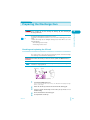

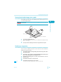


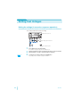


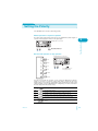
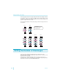
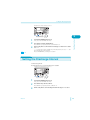
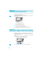
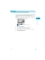
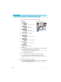

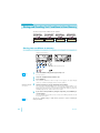
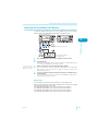
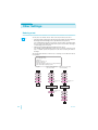
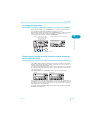


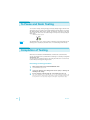

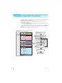
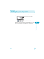
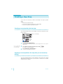
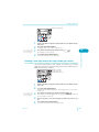
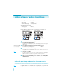


![静電気放電シミュレータ[KES4021A/4022A]](http://vs1.manualzilla.com/store/data/006582924_2-c8b53339fcebb946ab6b00af6a3f94bc-150x150.png)