1
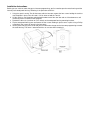
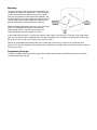
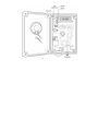
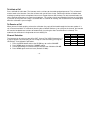
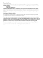
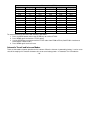
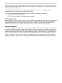
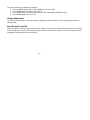
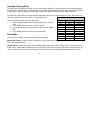
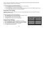
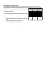
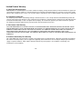
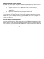
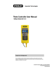
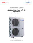
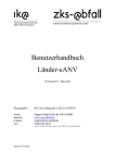
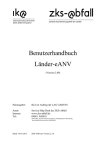
IO-738 User Manual
MURS Multi-Mile Wireless Communication System
User Guide Version 1.1
Table of Contents
Introduction........................................................................................................................................................................................ 3
Federal Communications Commission (FCC) Warnings ................................................................................................................... 3
MURS Frequencies ........................................................................................................................................................................... 3
Power Supply .................................................................................................................................................................................... 4
Power and Gate Control Relay Connector......................................................................................................................................... 4
Antenna Connector............................................................................................................................................................................ 4
Antenna Mounting.............................................................................................................................................................................. 4
Installation Instructions ...................................................................................................................................................................... 5
Mounting............................................................................................................................................................................................ 6
Programming Changes...................................................................................................................................................................... 6
To Initiate a Call................................................................................................................................................................................. 8
To Receive a Call .............................................................................................................................................................................. 8
Channel Selection.............................................................................................................................................................................. 8
Transmitter Power ............................................................................................................................................................................. 9
Interference Eliminator Codes ........................................................................................................................................................... 9
Automatic Turnoff and Intercom Modes........................................................................................................................................... 10
Battery Power Alert.......................................................................................................................................................................... 11
Squelch Adjustment......................................................................................................................................................................... 11
Volume Adjustment.......................................................................................................................................................................... 12
Busy Channel Lock Out ................................................................................................................................................................... 12
Gate/Door Opening Relay ............................................................................................................................................................... 13
Relay Mode ..................................................................................................................................................................................... 13
Relay Closure Time Setting ............................................................................................................................................................. 14
Change to Default Settings.............................................................................................................................................................. 14
Monitor Mode Tone Code Selection ................................................................................................................................................ 15
Limited Product Warranty ................................................................................................................................................................ 16
Specifications .................................................................................................................................................................................. 18
-2-
Introduction
The IO-738 MURS Multi-Mile Wireless Communication System is for use at locked entrances or remote gates and it
not only enables two-way voice communication, but you can also use its built in switch to unlock a door or gate that
has an electric opener. Its metal housing, stainless steel front, and water-tight internal housing make it both vandal
and weather resistant. You can use this intercom at residential gates, office building main entrances, or anywhere
two-way communication is needed.
The intercom also has a monitor mode that enables you to listen in to the sounds around the intercom for 15 seconds
when it receives a 2-Tone signal from a radio (not included).
The intercom uses an externally mounted antenna that you can mount away from the intercom and as high as
possible to increase the range the intercom will transmit. The back of the intercom has mounting holes for wall or
gooseneck pole mounting, plus a cable routing hole so you can route the antenna cable, switch control wires, and
power supply wires for an attractive installation.
Federal Communications Commission (FCC) Warnings
This device is intended to be used in such a way that a separation distance of at least 40 centimeters (15.75 inches)
is maintained between the antenna and any part of the user’s body. Ensure that the antenna is mounted at least that
far from the intercom, and for greater range, as high as possible. This device is certificated in accordance with Part
95, Subpart J of the Commission’s rules. Per these rules, operation of this device must not cause harmful
interference and it must accept any interference that may cause undesired operation.
MURS Frequencies
MURS is short for Multi-Use Radio Service. This is service created by the FCC in the United States. It is a low power
service in the VHF (Very High Frequency) 150 MHz two-way radio spectrum in which you do not need a license to
-3-
operate a station. With MURS you can use the external antenna to improve range. You can add an unlimited number
of MURS units together.
Power Supply
The intercom can be powered from any 9-13 Volt DC power source that supplies a minimum of 1 amp of current.
This power could be from an AC to DC adapter, a 12-volt car battery, 12V power from a gate controller, or a solarpanel power source with a battery.
Wire Color Function
Red
+9-13 Volts
Power and Gate Control Relay Connector
Brown
Ground
The cable for external power and the switch relay routes out the bottom of the housing
Yellow
Relay
Pin 1
through a liquid-tight nylon cable gland, also known as a cord grip. This allows connection
Pink
Relay
Pin
2
of a power source, and a 1-amp contact switch closure output. The same cable also has
Blue
Call
Btn.
1
wire pairs for the call button. See the table for colors and functions.
Green
Call Btn. 2
Antenna Connector
At the bottom of the internal waterproof housing is an SMA Female connector that is used to connect an external
antenna (one is provided). Simply route the antenna cable through the back of the vandal-proof steel housing and
screw the connector of the cable onto the antenna connector. After routing all wires through the center hole on the
back, insert the provided cable bushing to protect the cable and prevent excess moisture from entering the housing.
Antenna Mounting
The antenna kit for the intercom consists of the antenna, mounting bracket, and cable. The cable provided with the
antenna is about three feet long. You can also use cable extenders to extend the cable at least 20 feet with minimal
signal loss (MURS antennas cannot legally be higher than 60 feet above the ground). The mounting bracket included
enables you to attach the antenna in a convenient location using screws or bolts you provide.
-4-
Installation Instructions
Before you can install or make changes to intercom programming, you first need to open the metal housing and the
internal plastic waterproof housing. Following is the procedure to do this:
1. Using the special security Torx bit that came with the intercom, remove the four screws holding the stainless
steel faceplate in place. You will need a 1/4" bit driver to hold the Torx bit.
2. Lift the stainless steel faceplate and attached hardware out of the steel box and set it face down on a soft
surface to prevent scratches to the faceplate.
3. Remove the four nuts (use 9mm or 5/16" socket) on the waterproof housing mounting brackets.
4. Flip the waterproof housing over and loosen the four screws holding its plastic cover in place using a Philips
screwdriver (the screws will remain in the top cover).
5. Set the plastic housing cover aside and you can now make changes to the intercom programming or mount
the steel housing. The cover is attached to wires so use care when removing it.
-5-
Mounting
The vandal-resistant steel housing can be mounted using
standard 5/16” lag bolts or regular bolts. There are two sets
of holes on the back of the steel housing. One set of four
holes are designed for use with gooseneck pedestals, and
the other two can be used for mounting to a pole or any flat
surface. Nylon washers are provided to use with the 5/16
bolts for the purpose of sealing out excess moisture.
Gooseneck pole mounting will require four (4) 3/4 inch long
5/16 inch carriage bolts with washers on both sides.
Galvanized or stainless steel bolts and washers are
recommended for maximum weather resistance.
In the middle of the intercom is a hole for the antenna, power supply, and relay wires. If you are using a gooseneck
pole, you can route the wires through the pole. For other installations you can mount the intercom over an electrical
box or you can drill a hole in the mounting surface for the cables.
Hole plugs are provided for mounting holes that are not being used so excess moisture can be kept out of the
housing. The steel housing does have drainage holes in the bottom so condensation or any water that gets inside the
housing can escape.
Programming Changes
The next illustration shows the positioning of the DIP switches, Menu button and Up/Down keys that are used for
making programming changes.
-6-
-7-
To Initiate a Call
Press and hold the call button. The intercom sends a call tone to alert radio equipped personnel. This call tone will
also be heard at the intercom. Once the call tone ends you will hear a beep. Continue to hold the call button down
and begin speaking into the microphone from an arm's length distance after the beep. For best communication, the
caller should be three feet or less from the microphone. The call tone is only transmitted the first time the call button
is pressed, or every time until a reply is received. After 15 seconds of inactivity, the call tone will be transmitted again
when the call button is pressed again.
To Receive a Call
When you are finished speaking, release the call button. Any reply will be heard through the intercom speaker. If a
call is not received within 15 seconds of releasing the call button and there is no activity on the channel, the intercom
will sound a low double tone and turn-off automatically (assuming the Auto Turnoff feature is activated). This
automatic turn-off feature is designed to conserve battery life.
Channel Frequency Bandwidth
Channel Selection
1
151.820 MHz 11.25 KHz
2
151.880 MHz 11.25 KHz
The intercom can be set to use one of five VHF “License Free” MURS frequencies. If
3
151.940 MHz 11.25 KHz
a channel appears on the display you can change to a new channel by pressing the
4
154.570 MHz 11.25 KHz
UP/DN keys. If not, follow this procedure:
5
154.600 MHz 11.25 KHz
1. Press the MENU button and use the UP/DN keys to scroll to CHANNE.
2. Press MENU again to select the CHANNE setting.
3. Use the UP/DN keys to select one of the channels from CH-001 to CH-005.
4. Press MENU again to exit and save. (Default: CH-001)
-8-
Transmitter Power
Power is limited to a maximum of 2 watts, but the intercom can also be set to 1 watt for shorter range or batterypowered applications. This setting is done via a single DIP switch. To change the power setting move DIP switch
number 1 as follows:
1. HI for 2 Watts
2. LO for 1 Watt. (default setting)
If you don’t need to communicate over long distances, you’ll want to try the one-watt setting first, even if you are
using an AC to DC converter. The two-watt setting may transmit your communications farther than required so other
people nearby could pick up your conversations if they are on the same channel and using the same interference
eliminator codes. Also, if you are using the 6-D battery pack, your batteries will be quickly discharged using the 2watt setting.
Interference Eliminator Codes
For any of the five channels, there are 38 interference eliminator codes. These are also called privacy codes or
CTCSS which stands for Continuous Tone Coded Squelch System.
These codes enable a two-way radio to keep the radio squelched (quiet) if the chosen code is not received with a
transmission. In other words, the speaker of the intercom is not turned on even though a transmission is received.
Technically speaking, a CTCSS tone code is a sub-audible tone/code which allows you to ignore (not hear) calls from
other parties who are using the same channel. With CTCSS it may seem like you have your own private channel but
other parties can still hear your calls if they set up their transceiver with the same tone code or no tone code.
The radio used to reply to a call from the intercom must be set to the same interference eliminator/CTCSS code or
the intercom will not hear a response (the transmitting radio may also not hear the intercom if it has a different
programmed interference eliminator code. The following table lists the available codes.
-9-
Code
EC01
EC02
EC03
EC04
EC05
EC06
EC07
EC08
EC09
EC10
EC11
EC12
EC13
Frequency
67.0
71.9
74.4
77.0
79.7
82.5
85.4
88.5
91.5
94.8
97.4
100.0
103.5
Interference Eliminator Codes (CTCSS)
Code
Frequency
EC14
107.2
EC15
110.9
EC16
114.8
EC17
118.8
EC18
123.0
EC19
127.3
EC20
131.8
EC21
136.5
EC22
141.3
EC23
146.2
EC24
151.4
EC25
156.7
EC26
162.2
Code
EC27
EC28
EC29
EC30
EC31
EC32
EC33
EC34
EC35
EC36
EC37
EC38
EC00
Frequency
167.9
173.8
179.9
186.2
192.8
203.5
210.7
218.1
225.7
233.6
241.8
250.3
None
To set the interference eliminator code, follow this procedure:
1. Press the MENU button and use the UP/DN keys to scroll to CTCSS.
2. Press MENU again to select the CTCSS setting.
3. Use the UP/DN keys to select one of the CTCSS codes from EC00 to EC38 (Code EC00 is interference
eliminator off. Default: EC01).
4. Press MENU again to exit and save.
Automatic Turnoff and Intercom Modes
There are two modes of power operation for the intercom. When the intercom is powered by battery, it can be set to
shut off the majority of its functions between calls to conserve battery power. In Automatic Turn Off mode the
- 10 -
intercom automatically shuts off whenever there is no activity for fifteen (15) seconds (activity means either the call
button has been pressed or a call has been received). Once the unit has turned itself off, it can only be turned back
on by pressing the call button. When Automatic Turn Off is enabled, the intercom is OFF and cannot receive a call
until the intercom first initiates a call.
If you want to operate the intercom in full intercom mode where it can receive calls at any time, then it is
recommended that you power it by a non-battery power source.
To change the power operation mode for the intercom, DIP switch 2 should be set as follows:
1. INT: Auto Turn Off enabled (default)
2. EXT: External AC adapter is used for full Intercom Mode
Battery Power Alert
If battery power is used, a low battery alert tone is transmitted when battery voltage drops below an acceptable level.
This low battery tone notifies receiving radios that the batteries should be replaced. During normal operation, the
receiving radio hears the normal call tone sound the first time the button is pressed. When batteries are low, an
audible multi-tone sound is transmitted to receiving radios every time the intercom button is pressed.
Squelch Adjustment
The squelch setting adjusts the threshold at which signals will open (un-mute) the audio channel. It acts to suppress
the audio output of the receiver in the absence of a sufficiently strong desired input signal. With the squelch level
correctly set, you will hear sound only when actually receiving a signal. Backing off the control will turn on the audio,
and the operator will hear white noise (also called squelch noise) if there is no signal present. There are 10 levels
from for the squelch adjustment. Select a level at which the background noise is just eliminated when no signal is
present. The larger the level number you select, the stronger the signal you need to receive, and the smaller the
receiving range. When squelch control is at level 0, the callbox will be in receiving mode only and cannot transmit.
- 11 -
To set the squelch level, follow this procedure:
1. Press the MENU button and use the UP/DN keys to scroll to SQL.
2. Press MENU again to select the SQL setting.
3. Use the UP/DN keys to select one of the SQL codes from L00 to L09 (Default: L04).
4. Press MENU again to exit and save.
Volume Adjustment
The volume of the intercom is adjusted simply by rotating the volume control. Turn the control right to make the
volume louder.
Busy Channel Lock Out
When the callbox is receiving, you cannot transmit. If there is activity on the channel when you press the call button,
a descending series of tones will alert you that you cannot transmit until the channel is clear. This feature prevents
two people from trying to talk at the same time.
- 12 -
Gate/Door Opening Relay
The intercom has the ability to activate a set of relay contacts (120VAC, 1-Amp relay) that can be used to activate a
gate controller, switch on a light, sound an alarm or any other application where remote control of an ON/OFF switch
is required. The intercom does this by decoding 2-tone signals from handheld and base station intercoms.
The table to the right shows the 2-tone decode combinations that can be used to activate the relay. Each of the five
channels is able to receive these tones and activate the relay.
Programmable 2-Tone Decode (Receive) Code
Code
Tone 1
Tone 2
D00
*
*
D01
330.5
569.1
D02
349.0
600.9
D03
368.5
634.5
D04
389.0
669.9
D05
410.8
707.3
D06
433.7
746.8
D07
457.9
788.5
Relay Mode
D08
483.5
832.5
The relay has two modes of operation, Momentary and Toggle:
D09
330.5
600.9
Momentary Closure: The relay switch is closed for 1-255 seconds when correct 2-Tone Decode Code is received.
This is the default operation.
To set the relay tone code, follow this procedure:
1. Press the MENU button and use the UP/DN keys to scroll to R1
TON.
2. Press MENU again to select the R1 TON setting.
3. Use the UP/DN keys to select one of the channels from D00 to
D09.
4. Press MENU again to exit and save. (Default: D08)
Toggle Closure: Switch alternately closes and opens when the correct 2-Tone Decode Code is received. After the
2-tone code is received the intercom transmits a single beep if the switch has been opened and a double beep if the
switch has been closed. The switch opens when the intercom turns off if it is programmed for Automatic Turn-Off.
- 13 -
There are two wires connected to the internal relay (yellow and pink) and they are routed outside the waterproof
enclosure through the liquid tight nylon cable gland.
To set the relay mode, use the following procedure:
1. Press the MENU button and use the UP/DN keys to scroll to R1 MOD.
2. Press MENU again to select the R1 MOD setting.
3. Use the UP/DN keys to select one between MOMENT (Momentary Closure) and TOGGLE (Toggle Closure).
4. Press MENU again to exit and save. (Default: MOMENT)
Relay Closure Time Setting
If Momentary Closure is chosen for the relay, then you can choose how long the relay stays closed. The setting is
between 1 and 255 seconds.
To set the relay timing, use the following procedure:
1. Press the MENU button and use the UP/DN keys to scroll to R1 TIM.
2. Press MENU again to select the R1 TIM setting.
3. Use the UP/DN keys to select from 001s to 255s.
4. Press MENU again to exit and save. (Default: 001s)
Change to Default Settings
To change all settings back to default value follow this procedure:
1. Press the MENU button. Use the UP/DN keys to scroll to CHANNE.
2. Press and hold MENU button for 3 seconds. Display shows “RESET”.
3. Use the UP/DN keys to select between YES or NO.
4. Press MENU again to exit and save.
- 14 -
Default Settings
Setting
Default
01
Channel
Relay
Momentary Closure
D08
Relay 2-tone code
001s
Relay time
D09
Monitor 2-tone code
EC01
CTCSS
L04
Squelch
Monitor Mode Tone Code Selection
The intercom has a Monitor feature that enables you to send a 2-Tone signal (default code D09) to the intercom
which activates the transmitter for 15 seconds so you can listen in to the area around the intercom. This feature does
not work when the unit is in Auto Turnoff Mode. During those 15 seconds,
Programmable 2-Tone Decode (Receive) Code
the button on the intercom can override the Monitor feature so a call can
still be made, however Monitor Mode will be deactivated then. You will not
Code
Tone 1
Tone 2
be able to transmit to the intercom until Monitor Mode times out or the a
D00
*
*
caller presses the Talk button.
D01
330.5
569.1
D02
349.0
600.9
If you are using the gate or door opening capability, make sure you select
D03
368.5
634.5
a different tone code than you chose for it unless you want to listen in as
D04
389.0
669.9
the caller is entering. The two features can be used together.
D05
410.8
707.3
D06
433.7
746.8
To set the monitor tone code, use the following procedure:
D07
457.9
788.5
D08
483.5
832.5
1. Press the MENU button and use the UP/DN keys to scroll to MT
D09
330.5
600.9
TON.
2. Press MENU to enter Monitor Tone Code setting.
3. Use the UP/DN keys to select D00 to D09.
4. Press MENU again to exit and save. (Default: D09)
- 15 -
Limited Product Warranty
A. What This Warranty Covers
Multi-Mile Wireless Communications, (hereafter called the Company) hereby warrants that this product manufactured, supplied or
repaired by the Company shall be free from material defects in materials and workmanship for a period of 12 consecutive months
after the date of shipment. Accessories such as power supplies and antennas have a 90-day warrantee after the date of shipment.
B. Limitation of Remedies
The Company and Customer acknowledge and agree that the Customer’s sole remedy under this Limited Warranty shall be the
repair or replacement of the Products or any components thereof which are determined by the Company to be materially defective
in material or workmanship or, at the sole option of the Company, the refund of the purchase price of the Products in question.
The Company shall not be liable for injury to property other than the Products themselves.
C. Disclaimers from Warranty
THIS LIMITED WARRANTY IS GIVEN IN LIEU OF ALL OTHER WARRANTIES, WHETHER EXPRESS OR IMPLIED. THERE
ARE NO WARRANTIES THAT EXTEND BEYOND THE FACE OF THIS LIMITED WARRANTY AS TO THE FITNESS OF THE
PRODUCTS HEREUNDER FOR ANY PARTICULAR PURPOSE. THE COMPANY HEREBY DISCLAIMS ANY WARRANTY,
WHETHER EXPRESS OR IMPLIED, THAT THE PRODUCTS HEREUNDER ARE MERCHANTABLE. DUE TO THE
UNIQUENESS OF EACH INSTALLATION, THE COMPANY DISCLAIMS ANY LIABILITY FOR RANGE OR COVERAGE OF THE
PRODUCTS.
D. Products Covered by This Warranty
This Limited Warranty shall extend to the Products and components thereof manufactured, supplied or repaired by the Company,
but shall not extend to products, parts or equipment supplied by other manufacturers and used by the Company to manufacture,
supply or repair the Products, which shall be warranted only for the period, purposes and conditions extended by such
manufacturers to the Company.
- 16 -
E. Automatic Termination of Warranty Obligations
Any obligation of the Company under this Limited Warranty shall automatically and immediately terminate, without notice from or
any further action by the Company, and the Company shall have no responsibility for damages of any kind as a result of the
occurrence of any of the following:
(i)
(ii)
(iii)
(iv)
Acts of God, accident, misuse, abuse or negligent use of the Products or any component thereof;
any repair or alteration of the Products or any component thereof made outside the Company’s facility, except
by an employee of the Company authorized to do so;
improper installation, use or operation (including both mechanical and electrical) of the Products or any
component thereof;
failure to provide normal maintenance for the Products or any component thereof.
F. Limitation on Damages (Consequential Damages Excluded)
The Company shall not be responsible for, nor does this Limited Warranty extend to, any consequential or incidental damages or
expenses of any kind or nature, regardless of the cause thereof or any knowledge which the Company may have regarding the
probability of the occurrence of such damages or expenses including, without limitation, injury to persons or property, loss of use
of the Products, lost goodwill, lost resale profits, work stoppage, impairment of other goods, breach of contract, negligence or such
other actions as may be deemed or alleged to be the cause of a loss or damage to the Customer, its agents, sub-distributors,
customers or any other persons.
G. No Other Warranties, Statements are Opinions
This Limited Warranty is in lieu of all other express or implied warranties of the Company and the Company does not assume, nor
does it authorize any person to assume on its behalf, any other obligation or liability, either verbally or in writing. The Company
and Customer agree that any statements and representations made by the Company outside of this Limited Warranty are only the
Company’s opinion, are not a part of the basis of the bargain and are not warranted to be accurate. The Company and Customer
further agree that if any statement by the Company in this Limited Warranty or in any agreement or correspondence, whether oral
or written, between the Company and Customer is construed as an affirmation or promise, it shall nevertheless not constitute a
warranty that the Products or any component thereof will conform to such affirmation or promise.
- 17 -
H. How to Get Warranty Service
To receive warranty service during the warranty period, you must send the defective product to the Company via a prepaid,
insured, trackable shipping method such as UPS or FedEx. Send packages to: Multi-Mile Wireless Communications, Attn.
Warranty Department, 8161 Highway 100, #194, Nashville, TN 37221. Please do not return the metal housing or support
brackets. Remove the plastic housing containing the electronics from inside the unit and just send that. Please specify in
as much detail as possible as to the nature of the problem. You must provide written proof of purchase date and deliver it along
with the product. The Company may choose to repair or replace a defective product with reconditioned product or parts, or totally
replace the product. The Company shall ship, at the Company’s expense, said replacement or repaired Product or component to
Customer via the lowest priced transportation available to the Company. However, the Company shall be obligated to ship and
pay only for deliveries within the United States of America. Replacements are covered for the balance of the original warranty
period.
I. Other Rights
This Limited Warranty gives Customer specific legal rights, and Customer may also have other rights which may vary
from state/province to state/province.
Specifications
Water-tight Enclosure Material: Polycarbonate (UL94-HB)
Transmission Maximum Output Power: 1.9408 Watts
FCC Emission Designator: 11K0F3E
Included Antenna Gain: 3 dB
Measurements: 7.2"H x 6.6"W x 3.6"D
38 CTCSS interference eliminator codes
Current draw... Auto Turn Off: 19mA - Receiving: 100mA Transmitting: 1-watt transmit: 570 mA - 2-watt transmit: 750 mA
- 18 -
Antenna Connector: 50 ohm Female SMA
Frequency Tolerance: 3.715 PM
Temperature Operation: -30C to +50C
On-board relay: 120 VAC @ 1 amp
2-Tone Decode
9-13 Volt DC power source, minimum of 1 amp of current
Frequencies: 151.820MHz; 151.880MHz; 151.940MHz;
154.570MHz; 154.600MHz