1
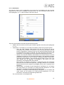
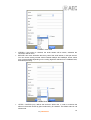
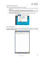
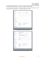
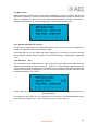
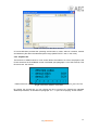
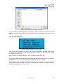
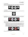
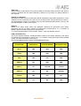
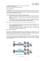
AEQ PHOENIX PC
USER’S MANUAL
ED. 01/12
CONTENTS
1. BASIC DESCRIPTION.............................................................................................................. 4
2. INTERNAL MENU..................................................................................................................... 6
2.1. Top bar............................................................................................................................. 7
2.1.1. FILE drop-down menu............................................................................................ 8
2.1.1.1. Open file for playing. ................................................................................. 8
2.1.1.2. Choose file to record to. ............................................................................ 9
2.1.1.3. Add Phonebook......................................................................................... 9
2.1.1.4. Add Station.............................................................................................. 10
2.1.2. TOOLS drop-down menu. .................................................................................... 13
2.1.2.1. Select a station........................................................................................ 13
2.1.2.2. Select audio I/O....................................................................................... 15
2.1.2.3. Go Live. ................................................................................................... 15
2.1.2.4. About. ...................................................................................................... 15
2.2. Main screen. .................................................................................................................. 16
2.2.1. Remote equipment to connect. ............................................................................ 16
2.2.2. Record to… File. .................................................................................................. 16
2.2.3. Playback file . ....................................................................................................... 17
2.2.4. On screen Vumeters. ........................................................................................... 18
2.3. Operating keys............................................................................................................... 19
2.3.1. Recording. ............................................................................................................ 19
2.3.2. Playback............................................................................................................... 20
2.3.3. Local audio source activation .............................................................................. 20
2.3.4. Connection to remote equipment. ........................................................................ 21
2.4. Sliding controls............................................................................................................... 22
3. OPERATION. .......................................................................................................................... 23
3.1. Installation...................................................................................................................... 23
3.2. Launching the application. ............................................................................................. 25
3.3. Initial configuration ........................................................................................................ 25
3.4. Establishing a connection . ............................................................................................ 26
3.5. Ending a connection. ..................................................................................................... 27
4. TECHNICAL SPECIFICATIONS. ........................................................................................... 28
4.1. Audio inputs/outputs. ..................................................................................................... 28
4.2. Supported hardware. ..................................................................................................... 28
4.3. Connectivity. .................................................................................................................. 28
4.4. Operating modes. .......................................................................................................... 28
4.5. IPv4................................................................................................................................ 28
4.6. SIP. ................................................................................................................................ 28
4.7. STUN. ............................................................................................................................ 28
4.8. Audio coding algorithms. ............................................................................................... 28
4.9. Disk size......................................................................................................................... 28
4.10. Recording format. ........................................................................................................ 28
5. AEQ WARRANTY................................................................................................................... 29
APPENDIX A: GENERAL CHARACTERISTICS OF CODING ALGORITHMS. ....................... 30
APPENDIX B: PROTOCOLS USED IN 3G AND IP NETWORKS. ........................................... 32
B1. Circuit switching versus packet switching. ..................................................................... 32
B1.1. Circuit switching. ................................................................................................... 32
B1.1.1. Advantages.............................................................................................. 33
B1.1.2. Disadvantages. ........................................................................................ 33
B1.2. Packet switching. .................................................................................................. 33
B1.2.1. Switching modes...................................................................................... 33
B1.2.2. Advantages.............................................................................................. 33
2
AEQ PHOENIX PC
B1.2.3. Disadvantages. ........................................................................................ 34
B2. IP Protocol. ..................................................................................................................... 34
B2.1. IP addressing. ....................................................................................................... 35
B2.2. Unicast vs. Multicast. ............................................................................................ 35
B2.3. 3G Communications. ............................................................................................ 36
B2.4. WIFI Communications........................................................................................... 36
B3. RTP Protocol. ................................................................................................................. 37
B4. SIP Protocol.................................................................................................................... 37
B4.1. Operating modes. ................................................................................................. 38
B4.2. Possible work scenarios. ...................................................................................... 40
B5. STUN Protocol................................................................................................................ 40
3
AEQ PHOENIX PC
1. BASIC DESCRIPTION.
AEQ Phoenix PC is a software application that turns your Windows based PC (MAC in future
updates) into a high quality audio codec (coding algorithms include MP2, AAC, AAC-HE, AACHEV2, G711, G722, ULCC, from 44.1 to 384 kbps) that connects bidirectionally -using raw RTP
traffic over UDP, direct SIP or Proxy-based SIP signaling protocols- with your Phoenix
audiocodec through IP networks, allowing your reporters to transmit their chronicles and
interviews and your collaborators to lively participate in your broadcastings, with radio quality
and using their own personal computer as the only technical equipment.
In order to achieve this, a connection with your Phoenix Studio, Phoenix Mobile or other unit of
the AEQ Phoenix family that is connected to the Internet is established thanks to the help of the
SIP server that AEQ provides. For more information, please check Appendix B of this manual.
Phoenix PC allows you to record while you send live audio, and playback pre-recorded files and
send them live, too.
AEQ Phoenix PC running in a laptop
AEQ Phoenix PC is available for download at the AEQ website. Once downloaded, ask your
AEQ dealer for a registration in the AEQ SIP server in order to be able to link to any of your
AEQ Phoenix codecs connected to the Internet through their IP port. With this data, your AEQ
Phoenix PC software is ready to send audio from a PC (MAC also in future versions) and
receive it from your Phoenix, establishing a high quality bidirectional link with low to moderate
delay (introduced by the network) that will make conversations possible. Paragraph 3.1 and
following ones of this manual describe the AEQ Phoenix PC download, installation and
activation procedures in detail.
AEQ Phoenix PC Logo
Even when the complete reading of this manual is strongly recommended before using the
product in order to gain a deep understanding of its different options and possibilities, a quick
start guide can be found in Chapter 3, describing the basic operation of AEQ Phoenix PC.
AEQ Phoenix PC is presented as a unit with professional performance, but simple operation
and low cost, within the Phoenix family of AEQ audiocodecs. At the time of writing this
document, the AEQ Phoenix family is composed of Phoenix Mobile, an audiocodec for portable
applications, Phoenix Studio, for stationary dual-channel uses, and a couple of software Apps
for iPhone.
4
AEQ PHOENIX PC
For more information about these products, please check:
http://www.aeq.es/spn/pr_phoenixstudio.htm
http://www.aeq.es/spn/pr_phoenixmobile.htm
http://www.aeq.es/spn/pr_phoenixpocket.htm
http://www.aeq.es/spn/pr_phoenixlite.htm
AEQ provides a PHOENIX STUDIO unit installed and available for testing that has the URI
“[email protected]“ (IP address: 212.170.163.189), as well as a SIP Proxy server
that is guaranteed to operate under the SIP official standard, with domain name
sip.aeq.es or IP address 82.165.157.20 (at the time of writing this manual).
5
AEQ PHOENIX PC
2. INTERNAL MENU.
AEQ Phoenix PC application, once downloaded and installed in your PC, presents a dedicated
access inside the Programs section in the Windows Start MENU.
Phoenix PC in Programs section of Windows Start Menu
The main screen of this software is divided into four main blocks or work areas:
•
•
•
•
Top bar: where the FILE and TOOLS drop-down menus are located.
Main screen: where you can see, from top to bottom, the remote equipment to be
connected, the file where you want to store a copy of the transmitted audio (if this option
is activated), the playback file you want to transmit live audio from (if this option is
activated), and a pair of VU-Meters showing the output and input audio levels from/to
the application.
Operating keys: that provide quick access to the most common operations: recording,
playout, ON/OFF for the local microphone, and connection to the remote equipment.
Sliding volume controls for the headphone output (at the bottom left of the screen) and
for the audio input defined in the PC (at the bottom right of the screen).
Phoenix PC main screen
6
AEQ PHOENIX PC
2.1. Top bar.
AEQ Phoenix PC top bar includes two drop-down menus: FILE and TOOLS.
The drop-down menu “FILE” allows you to manage the files where you want to store a copy of
the transmitted audio at, the source files to be played back real-time, as well as the remote units
you may want to establish a connection with.
FILE menu detail
The drop-down menu “TOOLS” provides access to the selection of the remote equipment to
connect to, among a previously created options list, as well as to the set up of the physical input
and output interfaces currently available at the PC (or MAC) hardware used.
TOOLS menu detail
7
AEQ PHOENIX PC
2.1.1. FILE drop-down menu.
You can find five options inside this menu:
•
•
•
•
•
Open file for playing: allows you to choose the source file from which you can’t to play
live audio from.
Choose file to record to: provides the selection of the file where a copy of the
transmitted audio may be stored at.
Add Phonebook: allows adding the contact information for a remote equipment from a
file or link.
Add Station: allows you to manually add the contact information for a remote unit.
Exit: option for quitting the application (Warning! NO confirmation is asked for when
performing this action).
Detail of FILE menu
2.1.1.1. Open file for playing.
Using this option you can use a file that will be played when the PLAY key is activated. (See
paragraph 2.2.3 of this manual).The file must have .wav format
Detail of the browsing for the playback file
In order to select the file to be played, follow the standard Windows procedures to browse
drives, folders, subfolders, etc. until you find the desired file. Then confirm by clicking on the
OPEN button.
We recommend that you double check that the name of the file is correctly displayed at the
second line of the main screen, as well as it duration in the format mins:secs.
8
AEQ PHOENIX PC
By default, files to be played back are stored in the path <LOCAL drive>/Program Files/Phoenix
PC, although this can be modified for your or your particular application’s convenience.
2.1.1.2. Choose file to record to.
Using this option you can choose or create a new file where the transmitted audio will be
recorded to, or simply to record audio from the physical audio input associated to the control
“Activate external audio source” (see paragraph 2.2.2. of this manual), when the REC control is
activated. The format of this file must be .wav.
Detail of browsing for the file to record to
Of course Windows provides the software operating environment to create, select & overwrite,
rename and delete any file within the selected options range (WAVE FILES *.wav, in this case).
By default, recorded files will be stored in the path <LOCAL drive>/Program Files/Phoenix PC,
although this can be modified for your or your particular application’s convenience.
2.1.1.3. Add Phonebook.
Using this option, agenda-like contacts can be added. Two working options are available: add a
contact From a File, or add a contact from its internet Address (From the Internet).
Detail of the FILE drop-down menu
In case you add contacts from a file, it must have the “comma separated values” (CSV) format,
and for addresses from internet, the usual “http://” format.
9
AEQ PHOENIX PC
2.1.1.4. Add Station.
This submenu allows for the configuration of a remote unit to be added to the list of remote
equipment you may want to establish connections with. For more information about this list,
check paragraph “2.1.2.1. Select a station” within this manual.
Detalle submenú ADD STATION
There are several fields to fill within the ADD STATION menu:
•
•
NAME: that the remote unit will be given inside the global contact list (check paragraph
2.1.2.1).
PROTOCOL: a list where you can select the operating mode among several options:
o RTP: the audio between AEQ Phoenix PC and the remote unit will be
transmitted using a stream of IP packets in RTP format (using UDP protocol).
No SIP configuration is required, that’s why the ADD STATIONS submenu will
be deactivated if this option is selected. For more information about RTP audio
transmission, check paragraph B3 of the Appendix B following this manual.
o N/ACIP: the connection between AEQ Phoenix PC and the remote unit will be
established according to the international standard for interoperability between
professional audiocodecs over IP networks, developed by EBU in their EBUTech3326 recommendation. This supposes that the audio is sent in RTP over
UDP packets and call signaling is exchanged in SIP format. For more
information, check Appendix B of this manual.
AEQ Phoenix PC supports connections in mode Direct SIP (the equipment
names will have the URI format equipment_name@IP_address) or Proxy-based
SIP (URI has the format: equipment_name@SIP_proxy_name, requiring user &
password).
o SHOUTCAST: a third-party format employed by third-parties. Do not employ
this mode unless you are asked to by AEQ technical department. For more
information, check http://en.wikipedia.org/wiki/SHOUTcast
o ICECAST: a third-party format employed by third-parties. Do not employ this
mode unless you are asked to by AEQ technical department. For more
information, check http://en.wikipedia.org/wiki/Icecast
For more information, check Appendix B.
10
AEQ PHOENIX PC
PROTOCOL options
•
•
•
•
•
SERVER: indicates the address of the SIP server to be used as a mediator in the
communication establishment. AEQ provides its own server, and is guaranteed to work
under the official SIP standard. Its name is sip.aeq.es
For more information relating to SIP servers, check Appendix B.4 of this manual.
STUN: indicates the address of the STUN server (useful to resolve private IP address in
public IP networks such as the Internet). Usually, public and freely available STUN
servers, available in Internet, are used. One of the most popular and reliable ones (at
the time of writing this document) is stun.voxgratia.org
For more information relating to STUN services, check Appendix B.5 of this manual.
USER: name for this license of AEQ Phoenix PC within the AEQ SIP Server. This
information is provided separately from the software by the AEQ sales department or
authorized dealers.
PASSWORD: associated to the user license registered in the AEQ SIP server. This
information is provided separately from the software by the AEQ sales department or
authorized dealers.
FORMAT: allows the selection of the audio coding algorithm to be used during the
connection with the remote equipment. You can choose among several options: MP2,
AAC-HE, G711, G722… Check Appendix A for more information.
11
AEQ PHOENIX PC
FORMAT menu detail
•
•
STEREO: if this option is checked, the audio stream will be stereo, otherwise the
connection will be mono.
BITRATE: this menu will define the binary rate of the audio stream, in bits per second.
You can choose among several values between 32Kbps and 384Kbps. Some values
may not be available depending on the coding algorithm selected in the FORMAT field,
described previously.
BITRATE list detail
•
JITTER – BUFFER (ms), defines the receiver’s buffer size, in order to minimize the
effects in the audio caused by jitter introduced by IP networks. The default value is 100
miliseconds.
12
AEQ PHOENIX PC
2.1.2. TOOLS drop-down menu.
There are four available options within this drop-down menu:
•
•
•
•
Select a station: allows the choice of the equipment to connect to from a previously
defined list.
Select audio I/O: defines the audio input and output hardware used by Phoenix PC
among the devices installed in the PC platform the software is running in.
Go Live: this option should be permanently selected in order to guarantee that the audio
transmission is made in real time.
About: offers some information about the software version and its manufacturer.
TOOLS drop-down menu detail
2.1.2.1. Select a station.
This submenu allows the selection of a remote equipment to connect within a list. The content
of this list, equivalent to a kind of agenda, has been previously defined with the option ADD
STATION from the FILE menu.
ADD STATION menu detail
13
AEQ PHOENIX PC
This ADD STATION submenu is not only a quick access to a list of remote units, but you can
also create new contacts (option “+”) or edit the existing ones (option EDIT).
In both cases (creating or editing a contact), the options you can find are identical to the ones
already described in paragraph 2.1.1.4. (ADD STATION) in this manual.
Option “+” for creating a new contact
Use option “EDIT” to modify an existing contact
14
AEQ PHOENIX PC
2.1.2.2. Select audio I/O.
This submenu is intended for the configuration of the audio input and output hardware, to be
selected among the several devices that may be installed in the PC platform the software is
running in.
SELECT AUDIO I/O submenu detail
2.1.2.3. Go Live.
By selecting this option you will return to the main screen directly, when you are inside some
configuration submenu.
It is very important that the GO LIVE option is selected in order to guarantee the operation of
this professional audio codec in real time.
2.1.2.4. About.
Provides information about the software version. This information is mandatory for any question
sent to the After Sales Technical Support.
ABOUT submenu detail
15
AEQ PHOENIX PC
2.2. Main screen.
Within this screen several pieces of information are displayed. From top to bottom, the name of
the remote equipment to connect, the file where the transmitted audio must be recorded (if this
option is configured), the file you want to be played and transmitted in real time (if this option is
configured), and a pair of vu-meters displaying the output and input audio levels.
Phoenix PC main screen
2.2.1. Remote equipment to connect.
The first line in AEQ Phoenix PC audiocodec displays the name of the remote equipment to
connect to (“AEQ test codec” in the previous image).
By clicking this line you can change the remote equipment, by choosing one from the list that
was previously created inside the SELECT A STATION submenu, as described in paragraph
2.1.2.1.
2.2.2. Record to… File.
The second line of the AEQ Phoenix PC main screen shows the name of the audio file (or its
absence) by displaying the legend “Record to… press me”. If this message is displayed you can
choose where to store the audio that is transmitted or simply present in the external audio input
selected, as described in paragraph 2.3.3 of this manual, once the REC symbol is pressed. This
file will be recorded in .wav format.
Detail of the main screen when the software is configured to record the transmitted audio to the
file “demo2 (003)”
By clicking this second line you can choose the file to record to in the standard Windows way,
as described in paragraph “2.1.1.2. Choose file to record to” of this manual.
16
AEQ PHOENIX PC
Detail of browsing for the file to record to
Of course Windows provides the operating environment to create, select & overwrite, rename
and delete any file within the selected options range (WAVE FILES *.wav, in this case).
2.2.3. Playback file .
The third line of AEQ Phoenix PC main screen allows the selection of a file to be played to the
IP line whenever the PLAYBACK control is activated (see paragraph 2.3.2 of this manual). This
file must have .wav format.
Detail of the main screen when the software is configured to play back “demo2_001” file. The
length of the file is shown in mins:secs
By clicking this second line you can choose the file to record to by following the standard
Windows procedures, as described in paragraph “2.1.1.1. Open file for playing” of this manual.
17
AEQ PHOENIX PC
Detail of the browsing for the file to play back
You can follow the standard Windows procedures in order to search for the file to play back
inside drives, folders, subfolders, etc. Once located, confirm your selection by clicking on Open
button.
2.2.4. On screen Vumeters.
Example of AEQ Phoenix PC main screen
Here you can see 2 horizontal vu-meters. The top one corresponds to the audio level received
from the remote equipment, and the bottom one displays the level of the physical audio input to
be transmitted or recorded.
Both vu-meters are calibrated between -50 and +2dB, with marks each 1dB.
The outgoing audio vu-meter (top one) will automatically display its level once the connection is
established. For more information please check paragraph 3.4 of this manual.
The bottom vu-meter indicates the level of the signal to be transmitted / recorded, and it is
directly related to the activation of the MIC or local audio source button. For more information,
please read paragraph 2.3.3 of this manual.
18
AEQ PHOENIX PC
2.3. Operating keys.
This buttons provide quick access to the most common operations to be performed with
Phoenix PC, such as recording, playout, activation of a local microphone (or other audio source)
and connection to a remote equipment.
Operating keys of Phoenix PC
2.3.1. Recording.
The recording key is the leftmost one, and is represented by the universally accepted circle
symbol. When activated, its color changes from grey to red.
Recording control key
The function of the recording key is not essential for the usual operation of AEQ Phoenix PC
when used as a real time portable audiocodec, although it may prove as a very useful feature
always at hand.
AEQ Phoenix PC connected to a remote unit (rightmost key) and recording the incoming signal
There exist several working modes for the RECORDING option, depending on the status of the
rest of operating keys:
•
•
When pressed together with the local audio source activation key (MIC icon), the
software operates as an autonomous recording station, as the incoming audio from the
physical input (either a microphone or a line input) is recorded to a file for your own
storing needs. That audio doesn’t exit the PC, except when the PLAYOUT function is
activated as described in paragraph 2.3.4 of this manual.
When activated together with the remote connection and local audio source activation
keys, the audio transmitted to the remote unit is also recorded live locally in a .wav file.
AEQ Phoenix PC offline and recording audio from a local source
All audio files are stored in .wav format.
19
AEQ PHOENIX PC
2.3.2. Playback.
The Playback key is located in the second position (starting by the left) among the four
operating keys. It is represented by the commonly accepted PLAY symbol (a triangle). When
activated, its color changes from grey to red and it changes to the PAUSE symbol (two parallel
rectangles).
Playback control key
The function of the Playback key is not essential for the normal operation of AEQ Phoenix PC
working as a real-time portable audiocodec. Nevertheless, it supposes a useful additional
feature always at hand. This key is associated to .wav audio files, which may be previously
captured using the RECORDING option of this program.
Playback key activated. During this phase, the PLAY symbol is changed to a PAUSE symbol
that can be used to temporarily stop playback.
There are several operation modes of the Playback function, depending on how it is combined
with the rest of operating keys:
•
•
•
When activated together with the remote equipment connection activation, the software
sends the content of the selected audio file to the other end.
When activated together with the local audio source activation key, it allows AEQ
Phoenix PC sending the contents of the file to the remote equipment, together with the
audio present in the local audio source. NOTE: during playback, the input from the local
source is muted, and when the file ends, it becomes unmated again.
When activated exclusively, the contents of the selected audio file is monitored at the
physical output that has been configured at the hardware the application is running in.
2.3.3. Local audio source activation .
The local audio source activation key is located in the third position (starting by the left) among
the four operation keys. It is represented by a microphone drawing. Its activation is denoted by
a change in color from grey to red. When no external microphone is activated but an audio
capture hardware is set up, the software may also work with line-level signals.
Local audio source activation key
There are several operation modes of the Playback function, depending on how it is combined
with the rest of operating keys:
20
AEQ PHOENIX PC
•
•
When activated together with the connection to remote equipment key, the audio
present at the defined hardware input will be sent to the other end of the
communication.
When activated together with the recording key, it allows recording the audio present at
the hardware input to the previously defined .wav file, thus using the software as a
portable audio recorder.
Local audio source activation key, together with remote connection key.
2.3.4. Connection to remote equipment.
The key for connection to remote equipment is the rightmost one. It is represented graphically
with an antenna symbol.
Connection to remote equipment key
The activation of this key implies launching a call or SIP connection to the previously configured
remote equipment (see paragraph 2.1.1.4 of this manual). There are three states associated to
the call, denoted by the different colors this key can be:
•
•
•
Grey: connection is not established, because it hasn’t been launched, or because it has
been rejected. This is an important difference that can only be determined by carefully
studying the following phases described.
Orange: connection is in progress. The call has been launched and negotiation of the
different communication parameters between the affected IP equipments is taking
place. This negotiation can end two ways: rejection or acceptation/establishment of the
call.
Red: connection has been successfully established. From this moment AEQ Phoenix
PC is in direct communication with the remote unit, exchanging full-duplex audio with it.
Connection in progress
Connection established successfully
21
AEQ PHOENIX PC
In order to complete the connection, it is necessary to click on the local audio source activation
key. From that very moment, AEQ Phoenix PC starts sending audio signal to the other unit and
the full-duplex connection is open, so incoming audio is now received from the remote unit.
NOTE: once the signal from the other end is received, the local audio input can be deactivated if
desired and it won’t affect the rest of the connection.
2.4. Sliding controls.
The lower part of the main screen shows two sliding level controls. The leftmost one represents
the volume of the output associated with the incoming audio, and the rightmost one represents
the gain of the audio input to be transmitted to the other end.
Volume control: -20dB to +20dB
Input gain control: -20dB to +20dB
Detail of sliding controls
Clicking over HP icons, audio output will be muted.
Clicking over Mic icon, audio from audio input is directly routed to local audio monitoring output.
22
AEQ PHOENIX PC
3. OPERATION.
In this section, a summarized guide of the operation of AEQ Phoenix PC is provided. A reading
of the former paragraphs is recommended in order to get a better understanding of the
described procedures.
Several basic points are assumed to be well-known along this manual and of course in this
operation guide, that are not described in greater detail because they are obvious. However,
they are enumerated below as a basic check list:
•
•
•
AEQ Phoenix PC is a PC-based professional audiocodec in software form that must be
installed on a PC platform running Windows operating system.
AEQ Phoenix PC is an IP professional audiocodec, so access to an IP (v4) network
must be available. It is designed as a public-network application, although it can of
course run flawlessly within private IP infrastructures, so it can be connected to either
type of network depending on each particular application. However, the first installation
must be performed on a PC with internet access in order to get the activation code
granted by AEQ as well as the registration data at AEQ SIP proxy server.
AEQ Phoenix PC is a software application running in protected mode, and doesn’t
include any hardware for audio input/output. In consequence, the PC it is installed on
must have is own sound adapter installed in order to operate as an audiocodec.
For more information about the technical characteristics of AEQ Phoenix PC, we recommend
the reading of section “4. TECHNICAL SPECIFICATIONS” in this manual.
3.1. Installation.
AEQ Phoenix PC software can be provided in many ways: as an attached file, via ftp or remotemailbox service, pre-stored on a CD, USB memory dongle or any other storage media. In any
case, it will be provided as a compressed ZIP file with the name PhoenixPC.zip and a size of
approximately 7MB.
The user must copy this file to the PC desktop and double-click on it, in order to launch the
installer for the application:
1. Some information will be gathered related to the application to be installed and
confirmation to create start-menu shortcuts. You must click on NEXT to go to the
following step, with no changes in the options checked by default.
Phase 1 of installation
23
AEQ PHOENIX PC
2. The installer will ask for a destination folder where the program will be installed at. By
default, it is Program Files\Phoenix PC. You must click on NEXT to go to the next step,
avoiding making any changes to the default parameters.
Phase 2 of installation
3. A progress bar will show the progress of the installation. This phase may take from 2-3
seconds to half a minute, depending on the processing power of the computer we are
installing AEQ Phoenix PC at.
Phase 3 of installation
4. Once correctly finished, a “Completed” message over the progress bar will appear.
Click on CLOSE to exit the installer.
5. The option Show Details will provide additional details if any problem occurs. Contact
AEQ Technical Assistance Service or an authorized dealer providing this data in case
that this happens.
Screen with details about the installation
24
AEQ PHOENIX PC
3.2. Launching the application.
In order to run AEQ Phoenix PC software, you only need to click on the AEQ Phoenix PC icon
located inside Programs/PhoenixPC folder within Windows Start menu.
Detail of Phoenix PC access inside Windows start menu.
AEQ Phoenix PC main screenshot
3.3. Initial configuration .
Following the procedure described in this paragraph is mandatory ONLY the first time
that AEQ Phoenix PC application is used.
The first time AEQ PHOENIX PC is run, it shows a license registration screen, that shows two
options:
•
REGISTER: allows for the registration of the application, permitting access to 100% of
its functionality. In order to accomplish this, the following fields must be filled in:
o NAME: name of the person, place, application or department that is going to
work with this license of AEQ Phoenix PC.
o ORGANIZATION: name of the company where the person, place, application or
department that is going to work with this application works for.
o EMAIL: address where the registration information/confirmation will be
received.
25
AEQ PHOENIX PC
ACTIVATION CODE: alphanumeric code required to activate the AEQ Phoenix
PC license. This information, together with the AEQ SIP proxy registration data
(user and password), are provided by AEQ sales department or authorized
dealers.
DEMO: allows the use of this application in demo / evaluation mode with limited
functionality (for example, one silence second is inserted every 20 seconds of
transmitted or received audio). No other field must be filled in this screen.
o
•
Detail of the license registering screen of AEQ Phoenix PC
3.4. Establishing a connection .
In order to establish a connection, the following steps must be followed, simply:
•
•
Define a remote equipment to connect to. For more information, read paragraph
“2.1.1.4 Add Station” in this manual.
Launch the connection by clicking on the “connection to remote equipment” key. For
more information, read paragraph “2.3.4. Connection to remote equipment” in this
manual.
In order to complete the connection, it is necessary to click on the local audio source activation
key. From that very moment, AEQ Phoenix PC starts sending audio signal to the other unit and
the full-duplex connection is open, so incoming audio is now received from the remote unit.
NOTE: once the signal from the other end is received, the local audio input can be deactivated if
desired and it won’t affect the rest of the connection.
26
AEQ PHOENIX PC
Example of established connection in AEQ Phoenix PC
•
In this situation, the software is reliably connected to a remote unit and several actions
can be performed:
o
o
o
o
Sending local audio from the physical audio input, by clicking on the “local
audio activation” key. THIS IS RECOMMENDED, because its activation
generates bi-directional RTP traffic that helps guarantying a reliable connection.
Play-back audio from a previously-recorded file, by clicking on the playback
key.
Record the transmitted audio to a file by clicking on the Recording key.
Any combination of the above modes.
3.5. Ending a connection.
In order to finish an already established connection, you only need to click on the “connect to
remote equipment” key. The key then changes its color from red (denoting active mode) to grey
(default inactive state). AEQ Phoenix PC is now ready to make a new call.
27
AEQ PHOENIX PC
4. TECHNICAL SPECIFICATIONS.*
4.1. Audio inputs/outputs.
The audio input/output characteristics are ultimately determined by the hardware used to run
the application. Check paragraph “2.1.2.2. Select audio I/O” in the present manual.
4.2. Supported hardware.
PC, laptop and netbooks running Windows XP, Windows Vista or Windows 7.
4.3. Connectivity.
The PC, laptop or netbook must have an IP connection, either wired-ethernet or wireless (WiFi
or 3G), and access to the Internet at least during the registration phase.
4.4. Operating modes.
•
•
•
•
RTP
N/ACIP (EBU-Tech3326 compliant)
Shoutcast
Icecast
4.5. IPv4.
IETF RFC1780 compliant
Transport protocol: RTP according to IETF RFC1889, RFC1890, RFC3550, RFC3551 and
RFC3711
4.6. SIP.
IETF RFC3261 compliant
AEQ SIP server address: 88.2.202.39
Ports: 5060 / 5061
Domain name: sip.aeq.es
User/User-ID: on demand (alphanumeric)
Password: on demand (alphanumeric)
4.7. STUN.
IETF RFC3489 compliant
Default STUN server: stun.voxgratia.org
Port: 3478
4.8. Audio coding algorithms.
•
•
•
•
•
•
•
G711 A-law
G711 µ-law
G722
MP2
HE-AAC
HE-AACv2
PCM16
4.9. Disk size.
7MB approx (ZIP compressed file with name “PhoenixPC.zip”)
Minimum disk free space for installation: 16MB
4.10. Recording format.
Raw WAV format
* Characteristics subject to change without notice.
28
AEQ PHOENIX PC
5. AEQ WARRANTY.
AEQ guarantees that this product has been designed and manufactured under a homologated /
certificated Quality Assessment System. Thus we guarantee that all the necessary test protocols
have been followed in order to ensure the correct functionality and that the specified technical
characteristics are met. The general design and manufacturing protocols as well as the details of this
product are documented properly.
AEQ guarantees that the delivered Phoenix PC software performs according to the technical and
functional characteristics described in the present manual.
•
This warranty doesn’t exclude or limit any customer’s legally-recognized right.
•
The warranty period extends for twelve months from the date of purchase by the first
customer.
In order to make use of this warranty the customer is required to inform of the problem to an
authorized dealer, any AEQ sales office, or AEQ technical support department within thirty
days from its appearance, and within the warranty period, as well as to provide a copy of the
purchase invoice and product serial number.
Technical Assistance Service AEQ Madrid
C/ Margarita Salas, 24
Parque Científico Leganes Tecnológico
28919 Leganes – Madrid - SPAIN
Tel: +34 91 686 13 00
Fax: +34 91 686 44 92
Email: [email protected]
Web: http://www.aeq.es/spn/soporte.htm
Technical Assistance service AEQ Miami
4121 SW 47 Avenue, Suite 1303
Fort Lauderdale FL 333314 USA
Tel: +1 954 581 7999
Fax: +1 954 581 7733
Email: [email protected]
Web: http://www.aeqbroadcast.com/soporte.htm
At the same time, AEQ Technical Assistance department’s previous and express acceptance
is required for the substitution or repair of the product in application of the present warranty.
Returns not meeting these conditions will not be accepted.
•
AEQ will repair or substitute failed the hardware dongles, which must be previously returned.
This includes the labor cost necessary to undertake this repair, provided that the failure is
caused by a defect in the materials, design or manufacturing. The repair will take place in
the AEQ Technical Assistance Service installations. This warranty doesn’t include the
shipping to the workshop nor the return. AEQ will replace the defective storing media or its
contents. In case that hidden faults appear, not known at the time of delivery of the software,
AEQ will provide a new version that will solve the issue(s).
•
Functional defects derived from a hardware that has not been homologated by AEQ fall
outside this warranty. Defects caused by the use of software, operating systems or versions
of them that have not been expressedly homologated or provided by AEQ fall outside this
warranty as well.
29
AEQ PHOENIX PC
APPENDIX A: General characteristics of coding algorithms.
This appendix briefly describes the different kinds of audio coding algorithms included in AEQ
Phoenix family of audiocodecs.
A summary is presented as well at the end of this appendix. This is a strongly
recommended reading, especially for new users, as it allows a better understanding of
the possibilities of interconnection between the different products within the AEQ
Phoenix family of audiocodecs.
G.711:
ITU-T standard for audio compression. This standard is mainly used in telephony, and its
license was made free in 1972.
G.711 is a standard for representation of audio signals within the human voice audio band, by
means of compressed digital audio samples with an 8KHz sampling rate. The G.711 encoder
generates a binary rate of 64Kbits/s. There are two common algorithms developed for this
algorithm: µ-law (used in North-America and Japan) and A-law (used in Europe and the rest of
the world where µ-law is not used)
Bandwidth: 3.5KHz
For more information, please check:
http://www.itu.int/rec/T-REC-G.711/e
G.722:
ITU standard for audio coding, based on ADPCM for audio signal processing in the humanvoice audio band, by means of compression of audio samples taken at a rate of 16KHz, for a
better sound quality and clarity.
This is the globally accepted mode for bidirectional communications due to its low delay, and
because of this it is widely used in commentary and sports reporting applications.
For more information, please check:
http://www.itu.int/rec/T-REC-G.722/e
Comparative of different audio coding algorithms
MPEG LAYER II:
This is a well-known and widely accepted coding mode, used when low delay is not mandatory,
as this family of algorithms always have a longer delay than G.722. There are several coding
modes variations at 64Kbps and 48, 32 or 24KHz sampling rates, and 128Kbps at 32 and
48KHz sampling rates.
Bandwidth: 10KHz to 15KHz.
For more information, check: ISO/IEC 11172-3 and ISO/IEC 13818-3.
30
AEQ PHOENIX PC
AEQ LD-2:
AEQ proprietary mode based on the previous AEQ-LD extended mode) where the low delay of
G.722 is combined with the wider bandwidth of MPEG, thus providing an optimal solution to
both aspects.
AAC-HE v1 (AACplus):
High Efficiency AAC is lossy compression method optimized for digital radio applications. It is an
extension of Low Complexity AAC (AAC-LC) for low binary rates, as audio streaming. Version 1
was standardized in 2003 by the MPEG group and was published within MPEG-4 group in the
document ISO/IEC 14496-3, Amd.1:2003.
AAC-LD:
MPEG-4 Low Delay Audio Codec was designed combining the perceptual audio coding
techniques with the low-delay required for bidirectional communications. It is a variation of
MPEG-2 Advance Audio Coding (AAC) coding format.
For more information please check: ISO/IEC 13818-7:1997 and ISO/IEC 13818-3.
PCM (12/16/20/24 bits):
This is the simplest waveform encoding possible, based on the regular sampling of the signal,
and subsequent quantification in binary form. It is a lossless coding providing the best possible
quality. For more information, please check:
http://www.digitalpreservation.gov/formats/fdd/fdd000016.shtml
ALGORITHM
PHOENIX PC
PHOENIX MOBILE
PHOENIX STUDIO
G711
YES
YES
YES
G722
YES
YES
YES
MP2
YES
YES
YES
AEQ LD
NO
YES
YES
AAC-LC
NO
OPTION
OPTION
AAC-LD
NO
NO
OPTION
HE-AAC
YES
YES
NO
PCM
L16
NO
YES
Summary of coding algorithms available In the AEQ Phoenix family of audiocodecs
31
AEQ PHOENIX PC
APPENDIX B: Protocols used in 3G and IP networks.
Communications through 3G or IP (3G are really IP networks) differ substantially from other
traditional communication architectures used in broadcast applications such as POTS and
ISDN, mainly because there are no dedicated resources in IP networks or guaranteed quality of
service implemented in most of the systems, what supposes several challenges to signaling,
establishment, keeping and releasing protocols of the communication.
These problems have their origin in the technical characteristics that are intrinsic to the
definition and operation of IP communications systems. The standard EBU-TECH 3326,
developed by N/ACIP working group provides several tools that help simplifying the operation,
making use of numerous protocols associated to IP communications, which will be described
below.
N/ACIP
• Signaling, including establishment and releasing the connection, as well as negotiation
of its parameters (audio coding algorithms, ports, etc.).
o SDP (Session Description Protocol) for the description of the parameters of the
connection.
o SAP (Session Announcement Protocol) for unidirectional multicast links.
o SIP (Session Initiation Protocol) simulates the operating mode (calling, hanging,
etc.) of conventional telephone networks.
• Transport, define the transport protocols over IP networks.
o RTP (Real-Time Transport Protocol) over UDP and IPv4.
o RTCP (Real-Time Control Transport Protocol) for synchronization and active
recovery functions.
o Defined IP ports: 5004 (RTP) and 5005 (RTCP).
This appendix doesn’t pretend to be a reference document for all technical questions, but at
least to serve as a first contact that provides familiarity with the new work method over 3G or IP
networks to the user of AEQ Phoenix family of audiocodecs, and hence eases operation. We
recommend that any user interested in getting a deeper knowledge of the underlying
technologies get access to the widely available IP technologies didactic material.
Along most of this appendix, technical concepts will be treated in a generic way for IP and 3G
connections, because although both protocols look different a priori, 3G networks are only a
particular case of IP networks with the particularity that the connections are wireless (the same
case as with WiFi networks) and that voice traffic is also supported. In a nutshell, all IP matters
treated here are equally valid for 3G, although this kind of wireless networks will be described
specifically in paragraph B2.3.
B1. Circuit switching versus packet switching.
The communications systems traditionally used in the broadcast environment for applications
with portable codecs have been mostly telephone or ISDN networks—that is, circuit switching
networks; PHOENIX, on the other hand, uses a packet switching network in its IP or 3G
interface.
B1.1. Circuit switching.
In a circuit switching network, the switching equipment must establish a physical path between
the communication media prior to the connection between users. This path remains active
during the communication between the users, and is cleared down or released when the
communication ends. Example: Switched telephone network.
Its operation passes through the following stages: request, establishment, file transfer and
connection release.
32
AEQ PHOENIX PC
B1.1.1. Advantages.
•
•
•
•
•
The transmission is made in real time.
Dedicated resources. The nodes that are involved in the communication use the
established circuit exclusively as long as the session lasts.
Once the circuit has been established, the parties can communicate with each other at
the highest speed that the medium allows, without having to share neither the
bandwidth nor the use time.
The circuit is fixed. Because a physical circuit is specifically dedicated to the
communication session in question, once the circuit is established there are no losses
of time for calculation and decision-making regarding routing through the intermediate
nodes. Each intermediate node has a single route for the incoming and outgoing
packets that belong to a specific session, which means it is impossible for the packets
to be disordered.
Simplicity in the management of intermediate nodes. Once the physical circuit has been
established, no further decisions are required to route the data from source to
destination.
B1.1.2. Disadvantages.
•
•
•
•
Delay in initiating communication. A time interval is required to make the connection,
which entails a delay in the transmission of the information.
Blockage of resources. No use is made of the circuit during the moments when there is
no transmission between the parties. Bandwidth is wasted while the parties are not
communicating with each other.
The circuit is fixed. The communication route is not readjusted; it is not adapted at each
opportunity to the least costly path between the nodes. Once the circuit has been
established, no use is made of the alternative, less expensive pathways that may
become available during the session.
Poor fault tolerance. If an intermediate node fails, the entire circuit crashes. The
connections then have to be re-established from zero.
B1.2. Packet switching.
The sender divides the message to be sent into an arbitrary number of packets of the same
size, to which a header and the originating and destination addresses are added, as well as
control data that will then be transmitted through different communication media between
temporary nodes until they reach their destination. This switching method is the one that is used
in today's IP networks. It has emerged to optimize transmission capacity through existing lines.
The temporary nodes store the packets in queues in their memories, which need not be very
large.
B1.2.1. Switching modes.
•
•
Virtual circuit: Each packet is routed through the same virtual circuit as the preceding
ones. Therefore the order of arrival of the packets to their destination is controlled and
ensured.
Datagram: Each packet is routed independently from the rest. Thus the network cannot
control the path followed by the packets, nor ensure the order in which they reach their
destination.
B1.2.2. Advantages.
•
•
•
In case of error in a packet, only that packet will be resent, without affecting other
packets that arrived without errors.
Interactive communication. Limiting the maximum packet size ensures that no user can
monopolize a transmission line for very long (microseconds), which means that packet
switching networks can handle interactive traffic.
Packet switching increases network flexibility and profitability.
33
AEQ PHOENIX PC
•
•
The pathway a communication takes can be altered from one moment to the next (for
example, in case one or more of the routers breaks down).
Theoretically, priorities can be assigned to the packets in a given communication. Thus,
a node can select, from its queue of packets waiting to be transmitted, the ones that
have higher priority.
B1.2.3. Disadvantages.
•
•
•
•
Greater complexity of the intermediate switching devices, which need to have higher
speed and greater processing power to determine the appropriate route for each
packet.
Packet duplication. If a packet takes too long to reach its destination, the receiving
device may conclude that it has been lost, in which case it will send a packet
retransmission request to the sender, which gives rise to the arrival of duplicate
packets.
If the routing calculations account for an appreciable percentage of the transmission
time, the channel throughput (useful information / transmitted information) decreases.
Variations in the mean transit delay of a packet in the network. This parameter is
commonly known as jitter.
B2. IP Protocol.
The Internet Protocol (IP) is a non-connection-oriented protocol used both by the origin and the
destination in data transmission over a switched packet network.
The data in an IP-based network are sent in blocks known as packets or datagrams (in the IP
protocol these terms are used interchangeably). In particular, in IP there is no need for
configuration before a device attempts to send packets to another with which it has not
communicated previously.
The Internet Protocol provides an unreliable datagram service called UDP (User Datagram
Protocol), also known as “best effort”, a phrase that expresses good intentions but offers few
guarantees, IP does not offer any mechanism to determine whether a packet reaches its
destination, and only provides security (by means of checksums) to cover its headers, and not
the transmitted data. For example, since it gives no guarantee that the packet will reach its
destination, it could arrive damaged, in the wrong order with respect to other packets,
duplicated, or simply not arrive. If reliability is needed, it is provided by transport layer protocols
such as TCP (Transport Control Protocol).
Reliability over TCP is obtained through the use of retransmissions. Real-time applications such
as an audio link, with the timing requirements inherent in the information contained in the link,
do not offer any useful guarantee. Since the data that are not received, and whose
retransmission is requested of the sender by the receiver, will in most cases arrive out of order,
they will end up as useless information that will have served only to overload the network. For
all these reasons, the protocol selected to serve as a communication substrate in real-time
applications is UDP.
UDP datagram
Protocols for transport over IP, independently of the reliability they offer, add new functionalities
to the basic ones provided by IP, such as packet numbering to facilitate, on the receiving end,
the detection of losses (although not their correction) and of disordering in the information
received; and the advent of the port concept as an identifier of different logia connections over
the same IP interface.
34
AEQ PHOENIX PC
For complete information on IP protocol, we recommend consulting:
http://tools.ietf.org/html/rfc791
http://www.iana.org/assignments/port-numbers
B2.1. IP addressing.
An IP address is a number that logically and hierarchically identifies an interface of a device in
a network that uses the IP protocol. The format used is X.X.X.X, where each X represents a
group of eight bits translated into decimal form—that is, whose minimum value is 0.0.0.0 and
whose maximum value is 255.255.255.255.
IP addresses are classified in two major groups: static and dynamic.
• It is typical for a user to connect to the Internet from his or her home using an IP
address. This address may change when the user reconnects, and this manner of
assigning IP addresses is called a dynamic IP address (normally abbreviated as
dynamic IP).
• The Internet sites that, by nature, need to be continuously connected generally have a
static IP address (as with the dynamic address, a similar abbreviated form is used:
static or fixed IP)—that is, an address that does not change over time.
Another possible IP address classification can be made according to address validity:
•
•
Public: IP addresses that are valid in the entire Internet network. Currently, due to the
poor management that has traditionally been applied to the available IP addresses, they
are a scarce, highly costly resource.
Private: addresses that are only valid in a closed section of the IP network, typically
corporate and not subject to free access, with only one point of connection to the
Internet, called a gateway, constituted by a router.
B2.2. Unicast vs. Multicast.
Unicast is the transmission of information from a single sender to a single receiver. It is
distinguished from multicast (transmission to certain specific recipients—more than one—from a
single sender), broadcast (in which the recipients are all the stations in the network) and
anycast (transmission to a single recipient—any unspecified recipient).
The unicast method is the one currently being used on the Internet, and is applied for both live
and on-demand transmissions. The multicast method can only be used in corporate
environments, despite some isolated efforts to introduce it on the Internet, and is applied only
for live transmissions.
Graphic Comparison: Unicast vs. Multicast
35
AEQ PHOENIX PC
The effect that unicast transmission has on network resources is accumulative consumption.
Each user who connects to a multimedia transmission consumes as many kilobits per second
as the content encoding will permit.
B2.3. 3G Communications.
3G is the acronym for third-generation voice and data mobile communications. The technically
correct definition is UMTS (Universal Mobile Telecommunications System).
3G is an expression commonly used to designate the transmission of data through a mobile
link, as the one provided by a 3G modem or a mobile device. This kind of communication could
be described in a very simple way as an IP connection using a 3G link. Thus we are referring to
the technology used to access a particular network, in this case Internet.
As stated before, once we abstract from the physical wireless transmission layer over UMTS
standard, the operation and technical characteristics are identical to the previously described IP
protocol.
For more information, consult your telecommunications provider.
B2.4. WIFI Communications.
Wi-Fi is a trade mark of the Wi-Fi Alliance (formerly known as WECA: Wireless Ethernet
Compatibility Alliance), the commercial organization that adopts, tests and certifies that each
particular equipment accomplish 802.11 standard related to wireless local area networks.
Official WiFi logo
There exist several Wi-Fi types, each one
IEEE 802.11 standard. These are some of them:
•
•
•
based
on
a
particular
approved
Standards IEEE 802.11b, IEEE 802.11g and IEEE 802.11n have a wide international
acceptance due to the fact that the 2.4 GHz radio band is almost universally licensefree. These standards provide a data rate of up to 11 Mbps , 54 Mbps and 300 Mbps,
respectively.
A recent addition is the IEEE 802.11a standard, also known as WIFI 5, operating in the
5 GHz band, that enjoys a relatively clean spectrum: the 5 GHz band has been recently
enabled and there are no other standard technologies using it ( (Bluetooth, microwave
links, ZigBee, WUSB), so it is almost interference-free. Its range is somewhat shorter
than that of the standards working at 2.4GHZ (10% less approximately) due to the
higher frequency (the higher the frequency, the shorter the range, generally speaking).
A first draft of IEEE 802.11n standard working at 2.4 GHz with a speed of 108 Mbps is
available. Several commercial devices are already available that allow the use of this
technology, known as Pre-N. However, 802.11g is already capable of those speeds,
thanks to different speed increase techniques.
There are other wireless technologies such as Bluetooth operating in the 2.4 GHz band, which
can produce interference with Wi-Fi. That’s why 1.2 version of Bluetooth specification was
updated to avoid interferences when both technologies are simultaneously used, and also
requires 40.000 k speed.
36
AEQ PHOENIX PC
For more information, please read:
http://en.wikipedia.org/w/index.php?title=File%3AWireless_Networking_in_the_Developing_Wor
ld.pdf&page=1
B3. RTP Protocol.
RTP are the initials of Real-time Transport Protocol. It is a transport level protocol used for the
transmission of information in real time, as occurs with audio and video. Normally it is paired
with RTCP (RTP Control Protocol) and is located on UDP.
The IP ports defined for its use are 5004 (RTP) and 5005 (RTCP).
The functions of the RTP/RTCP protocol are:
•
•
•
Management of the reception buffer in order to minimize the jitter effect introduced by
the network.
Recovery of the reference clock based on information inserted by the transmitting
equipment.
Test tools to permit the user to verify the bandwidth, the delay and estimated jitter in the
connection.
RTP Header
For complete information on RTP/RTCP protocol, we recommend consulting:
http://tools.ietf.org/html/rfc1889
http://tools.ietf.org/html/rfc1890
http://tools.ietf.org/html/rfc3550
http://tools.ietf.org/html/rfc3551
http://tools.ietf.org/html/rfc3711
B4. SIP Protocol.
Session Initiation Protocol (SIP) is a protocol developed by the IETF MMUSIC Working Group
with the intention of establishing the standard for initiating, modifying and finalizing interactive
user sessions involving multimedia elements such as video, voice and instant messaging.
SIP is used simply to initiate and terminate voice and video calls. Once the communication is
established, the exchange of voice / video information is conducted only over RTP.
One of the objectives of SIP was to contribute a set of processing functions to apply to calls and
capabilities present in the public switched telephone network. Thus, it implemented typical
functions that a common telephone terminal offers, such as: calling a number, making a
telephone ring when called, hearing a dial tone or busy tone. The implementation and
terminology in SIP are different.
37
AEQ PHOENIX PC
SIP requires proxy servers and register elements to give a practical service. Although two SIP
terminals can communicate with each other without the mediation of SIP infrastructures through
the use of URIs of the name@IP-address type (which is why SIP is defined as a point-to-point
protocol), this approach is impracticable for a public service because of the problems inherent in
IP addressing, where obtaining static public addresses is nearly impossible and extremely
costly.
SIP makes use of elements called proxy servers to help route the requests toward the user’s
current location, authenticate users to give them service, enable call routing policies to be
implemented, and contribute added capabilities to the user.
SIP also contributes register functions that enable the user to inform the proxy servers of his or
her location.
To simplify the operation of the Phoenix family of audiocodecs, AEQ offers, at no
additional cost, the services of its own SIP Proxy server, although it cannot guarantee its
operation 100% of the time, nor be held responsible for the inconveniences that this may
produce for the end user. The unit leaves the factory preconfigured with the parameters
required to work with the resources of this SIP server.
For complete information on the SIP protocol, we recommend consulting:
http://tools.ietf.org/html/rfc3261
B4.1. Operating modes.
AEQ PHOENIX PC will start in N/ACIP mode and it will connect and register automatically in the
SIP proxy server configured in its memory, by indicating its name (URI: name@domain –
“name” is enough under certain circumstances) and position (IP Address).
In order to establish any communication, the unit that wishes to start the communication will
search the SIP Proxy server register for the information regarding the called device and will
redirect the call—in a way that is transparent to the user—toward the real physical place where
the device is located.
38
AEQ PHOENIX PC
1
2
3
SIP protocol operation diagram. Phase 1: Registration. Phase 2: Search for the called device in
the SIP server database. Phase 3: Establishment of the connection
39
AEQ PHOENIX PC
This working method, supported by external SIP servers, enables the physical position of a
device to be made independent from its logic identifier and, through the use of the SIP protocol,
makes it unnecessary to know more data regarding the called device than its URI.
During the establishment of the communication phase, the encoding algorithm is negotiated
simultaneously, based on the Link Profiles / SIP Codec Profiles defined in each of the devices
at the two ends of the connection circuit.
B4.2. Possible work scenarios.
Depending on the type of network to which the PHOENIX STUDIO is connected, the codec will
have one or another type of IP address available to it.
•
•
Static public IP addresses offer the ideal situation, since they guarantee that the IP
interface of the codec will always be assigned to a fixed address (regardless of whether
it is turned off and then powered up again) and directly accessible to the rest of the
network users. This situation, as stated before, is not common, due to the high cost and
limited number of available IP addresses.
Dynamic public IP addresses, corresponding to use an Internet access by means of a
single workstation router and a dynamic IP (the most usual). Allows the use of URIs of
the name@domain (PROXY SIP) or name@IP-address (DIRECT SIP) type, but it is
advisable always to work with an associated SIP server (PROXY SIP), since the IP
address assigned to the equipment may change each time the user powers up the unit.
This is the common situation in 3G connections and also for some Wi-Fi connections.
Private IP addresses, both static and dynamic, corresponding to connections in a local
network with several workstations, that access to the Internet through a router with
NAT. Those do not allow the use of URIs of the name@IP-address type because the IP
address of the identifier is not public, and is only valid in the section of the network to
which it has been assigned; it lacks a universal meaning. In this case the use of an
associated SIP server and a STUN server is imperative to get past the NAT (Network
Address Translation) implemented in the router that acts as an interface between the
private network and the public one. This is a very unlikely situation in 3G networks
although depending on the network structure it may be quite typical in Wi-Fi
connections on corporate networks.
B5. STUN Protocol.
STUN (Simple Transversal of UDP over NATs) is a network protocol of the client /server type
that allows NAT clients to find their public IP address, the type of NAT where it is located and
the Internet port associated with the local port through NAT. This information is used to
configure a UDP communication between two hosts located behind NAT routers.
NAT (Network Address Translation) is a mechanism used by IP routers to exchange packets
between two networks that assign each other incompatible addresses. It consists of converting,
in real time, the addresses used in the transported packets. It is also necessary to edit the
packets to enable the operation of protocols that include address information within the protocol
conversation. It is most commonly utilized to enable the use of private addresses and still
provide connectivity with the rest of the Internet.
AEQ PHOENIX codecs include a STUN client that sends a request to a STUN server. The
STUN server then informs the client of its public IP and which port has been opened by NAT to
permit incoming traffic to enter the client’s network. This information enables the AEQ PHOENIX
codec to identify its position within the SIP server.
40
AEQ PHOENIX PC
Registering in the STUN server
Notification from the server of the corresponding NATs detected
41
AEQ PHOENIX PC
The response further enables the STUN client to determine the type of NAT being used, since
different NAT types handle incoming UDP packets in different ways. STUN supports three of the
four main existing types of NAT: Full Cone, Restricted Cone and Port Restricted Cone. It does
not, however, support Symmetric NAT, also known as bidirectional NAT.
Once the client has discovered its public address, it can advise its peers of that address.
STUN is useful as a complement to protocols like SIP. SIP uses UDP packets to signal sound,
video and text traffic over the Internet, but does not enable communication to be established
when the devices at the ends of the communication circuit are behind NAT routings. This is why
STUN is customarily used in these applications, to permit communication to be established.
The connection with the STUN server is normally made through port 3478 by means of UDP.
The STUN server can then provide the client with an alternate IP and communication port.
For complete information on the STUN protocol, we recommend consulting:
http://tools.ietf.org/html/rfc3489
It is not common (although not impossible) that STUN configuration presents problems within
normal operation of AEQ Phoenix, although of course it depends heavily on the 3G network
configuration and the gateways to Internet each telecom provider offers.
However, these issues associated with NAT traversal are more commonly found in
transmissions over WiFi networks using AEQ Phoenix PC and especially in standard IP
networks with AEQ Phoenix Studio, AEQ Phoenix Mobile or AEQ Phoenix PC connected inside
private LANs with public router.
RECOMMENDATION: in order to avoid the inherent configuration complexity of the STUN
associated parameters, arising from the very wide NAT casuistry for the different networks (and
from the fact that highly skilled technicians are required to undertake that configuration), AEQ,
basing on its long experience in the design and deployment of STUN-equipped codecs,
recommends the subscription of a ADSL dedicated access (single-host) for the receiving end
of the communication (usually implemented with AEQ Phoenix Studio or AEQ Phoenix Mobile
units). For more information, please ask our Technical Assistance Service or one of our
authorized dealers.
42
AEQ PHOENIX PC