1
O
Operating Manual
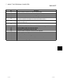
Operating Manual
GX RemoteService-I Version 1 Operating Manual
MODEL
SW1D5-RAS-O-E
MODEL
CODE
13JU23
SH(NA)-080204-A(0112)MEE
HEAD OFFICE : 1-8-12, OFFICE TOWER Z 14F HARUMI CHUO-KU 104-6212,JAPAN
NAGOYA WORKS : 1-14 , YADA-MINAMI 5 , HIGASHI-KU, NAGOYA , JAPAN
When exported from Japan, this manual does not require application to the
Ministry of Economy, Trade and Industry for service transaction permission.
Specifications subject to change without notice.
SW1D5C-RAS-E
• SAFETY PRECAUTIONS •
(Always read these instructions before using this equipment.)
Before using this product, please read this manual and the relevant manuals introduced in this manual
carefully and pay full attention to safety to handle the product correctly.
The instructions given in this manual are concerned with this product. For the safety instructions of the
programmable controller system, please read the CPU module user's manual.
In this manual, the safety instructions are ranked as "DANGER" and "CAUTION".
DANGER
Indicates that incorrect handling may cause hazardous conditions,
resulting in death or severe injury.
! CAUTION
Indicates that incorrect handling may cause hazardous conditions,
resulting in medium or slight personal injury or physical damage.
!
Note that the ! CAUTION level may lead to a serious consequence according to the circumstances.
Always follow the instructions of both levels because they are important to personal safety.
Please save this manual to make it accessible when required and always forward it to the end user.
[Design Instructions]
!
CAUTION
• The user should take necessary measures when the PLC system must be secured against
illegal access from external devices via the Internet.
A-1
A-1
REVISIONS
* The manual number is given on the bottom left of the back cover.
Print Date
Dec., 2001
* Manual Number
SH (NA) 080204-A First edition
Revision
Japanese Manual Version SH-080203-B
This manual confers no industrial property rights or any rights of any other kind, nor does it confer any patent
licenses. Mitsubishi Electric Corporation cannot be held responsible for any problems involving industrial property
rights which may occur as a result of using the contents noted in this manual.
2001 MITSUBISHI ELECTRIC CORPORATION
A-2
A-2
INTRODUCTION
Thank you for choosing the Mitsubishi MELSOFT series Integrated FA software.
Read this manual and make sure you understand the functions and performance of MELSOFT series
thoroughly in advance to ensure correct use.
Please make this manual available to the end user.
CONTENTS
SAFETY PRECAUTIONS..............................................................................................................................A - 1
REVISIONS ....................................................................................................................................................A - 2
CONTENTS....................................................................................................................................................A - 3
About Manuals ...............................................................................................................................................A - 5
How to Use This Manual................................................................................................................................A - 6
About the Generic Terms and Abbreviations ...............................................................................................A – 8
Product Makeup ............................................................................................................................................A – 9
1. OVERVIEW
1- 1 to 1- 4
1.1 Features ................................................................................................................................................... 1- 1
1.2 About Automatic Operation and Manual Operation................................................................................ 1- 3
2. SYSTEM CONFIGURATION
2- 1 to 2-12
2.1 System Device List................................................................................................................................... 2- 1
2.1.1 Connection from the serial port......................................................................................................... 2- 2
2.1.2 Connection from the interface boards .............................................................................................. 2- 5
2.1.3 System equipment lists ..................................................................................................................... 2- 7
2.2 Operating Environment............................................................................................................................ 2-11
2.2.1 Server (personal computer) .............................................................................................................. 2-11
2.2.2 Personal computer ............................................................................................................................ 2-12
3. FUNCTION LIST
3- 1 to 3- 2
3.1 Server (Personal Computer) Function List.............................................................................................. 33.2 Personal Computer Side Function List.................................................................................................... 33.2.1 Monitor functions ............................................................................................................................... 33.2.2 Functions to cut off server (personal computer) line from personal computer................................ 34. PRE-OPERATION SETTINGS AND PROCEDURES
1
2
2
2
4- 1 to 4- 4
4.1 Server (Personal Computer) Setting Procedure ..................................................................................... 4- 2
4.2 Personal Computer Setting Procedure ................................................................................................... 4- 4
5. INSTALLATION OF WEB SERVER SOFTWARE
5- 1 to 5- 9
5.1 Windows 98 ............................................................................................................................................ 5- 1
5.2 Windows NT 4.0 ..................................................................................................................................... 5- 4
5.3 Windows 2000........................................................................................................................................ 5- 7
R
R
R
A-3
A-3
6. SETTING THE GX RemoteService-I FUNCTIONS
6- 1 to 6-19
6.1 Setting Wizard .......................................................................................................................................... 6- 2
6.2 Main Screen ............................................................................................................................................. 6- 3
6.3 Setting the Server (Personal Computer) Functions ................................................................................ 6- 5
6.3.1 E-mail setting..................................................................................................................................... 6- 5
6.3.2 Dialup setting..................................................................................................................................... 6- 7
6.3.3 PLC type setting ................................................................................................................................ 6- 8
6.3.4 Connection setup .............................................................................................................................. 6-10
6.3.5 Device range setting ......................................................................................................................... 6-14
6.3.6 Tag setting......................................................................................................................................... 6-15
6.3.7 Automatic operation setting .............................................................................................................. 6-17
6.3.8 Device display format setting............................................................................................................ 6-19
7. ABOUT THE PERSONAL COMPUTER
7- 1 to 7- 6
7.1 List of Personal Computer Setting Items................................................................................................. 77.2 Providing Tag Display .............................................................................................................................. 77.3 Monitoring the Devices ............................................................................................................................ 77.4 Setting the Server (Personal Computer) Line Connection ..................................................................... 78. GETTING STARTED WITH GX RemoteService-I!
1
3
4
6
8- 1 to 8-16
8.1 Setting GX RemoteService-I to the Server (Personal Computer).......................................................... 8- 1
8.2 Varying of Monitor Devices and Arrival of E-mail.................................................................................... 8-11
8.3 Receiving E-mail and Looking at Devices on Personal Computer......................................................... 8-12
8.3.1 Until looking at tag............................................................................................................................. 8-12
8.3.2 Until looking at devices ..................................................................................................................... 8-14
9. TROUBLESHOOTING
APPENDICES
9- 1 to 9- 3
App- 1 to App- 2
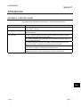
APPENDIX 1 RESTRICTIONS..................................................................................................................App- 1
INDEX
A-4
Index- 1 to Index- 2
A-4
About Manuals
The following lists the manuals for this software package.
Refer to the following table when ordering manuals.
Related Manuals
Manual Number
(Model Code)
Manual Name
GX Developer Version7 Operating Manual
Describes the online functions of GX Developer including the programming procedure, printing out
procedure, monitoring procedure, and debugging procedure.
A-5
SH-080166
(13JU14)
(Sold separately.)
A-5
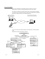
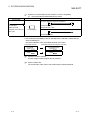
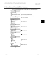
How to Use This Manual
"How to Use This Manual" is described purpose by purpose for use of GX
RemoteService-I. Refer to the following description and use this manual.
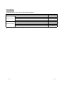
This system is divided into a personal computer and a server (personal computer).
The system can be introduced smoothly by making actual setting while checking the
purposes and setting sequence in the following flowchart.
Server (Personal computer)
Personal computer
Personal computer
Internet
Mobile phone
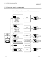
For the server (personal computer) setting, set the automatic or manual operation
mode.
The personal computer side setting is required.
Use GX RemoteService-I
Server (personal
computer) side
Set the server
(personal computer) or
personal computer
side setting
Grasp the setting items and
procedure on the personal computer.
Refer to Section 4.1
Personal computer side
Prepare the personal
computer to be used on
the personal computer side.
Refer to Section 4.2
Automatic
operation mode
Select the operation
mode
Manual
operation mode
Personal computer side
functions
Refer to Chapter 7
Set the GX RemoteService-I
functions corresponding to
automatic operation
Set the GX RemoteService-I
functions corresponding to
manual operation
Refer to Chapter 6
Refer to Chapter 6
Operation start
Operation method
Getting started with
GX RemoteService-I!
Refer to Chapter 8
Operation start
A-6
A-6
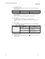
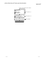
(1) When you want to know features or automatic or manual operation
(Section 1.1, Section 1.2)
Section 1.1 gives the features.
Section 1.2 describes automatic operation and manual operation.
(2) When you want to know the operating environment of GX
RemoteService-I (Section 2.2)
Describes the specifications of the personal computer used on the server
(personal computer) side.
(3) When you want to know the initial setting of the server (personal
computer) and personal computer (Section 4.1, Section 4.2)
Describes the procedures for setting the personal computer used on the server
(personal computer) side and the personal computer used on the personal
computer side.
(4) When you want to know the functions set with the server
(Chapter 6)
Provides the detailed explanation of the functions to be set.
Also gives the explanation of the easy and convenient Wizard for use.
(5) When you want to know the functions of the personal computer
(Section 7.1 to Section 7.4)
Describes the procedure for monitoring devices and comments from the personal
computer.
(6) When you want to operate GX RemoteService-I anyhow (Chapter 8)
Explains the procedures for setting the server (personal computer), sending email and making access from the personal computer to the server (personal
computer).
(7) When you want to know the actions to be taken at occurrence of
problems (Chapter 9)
Describes the troubleshooting to avoid trouble.
(8) When you want to know restrictions (Appendices)
Describes the restrictions on use of GX RemoteService-I.
A-7
A-7
About the Generic Terms and Abbreviations
Unless otherwise specified, this manual uses the following generic terms and abbreviations to describe GX
RemoteService-I.
Generic Term/Abbreviation
GX RemoteService-I
PWS
IIS
Web server software
Windows 2000
WindowsNT 4.0
Windows 98
R
R
R
Windows
R
Description
Generic product name of the product types SWnD5C-RAS-E, SWnD5C-RAS-EA.
Generic term for Personal Web Server.
Generic term for Internet Information Server.
Generic term for Personal Web ServerInternet Information Serve.
Microsoft Windows 2000 Professional Operating System.
Microsoft WindowsNT Workstation 4.0 Operating System.
Microsoft Windows 98 Second Edition Operating System.
Microsoft Windows 98 Operating System.
Microsoft WindowsNT Workstation 4.0 Operating System.
Microsoft Windows 2000 Operating System.
Generic term Q02(H),Q06H,Q12H,Q25HCPU.
Generic term Q00J,Q00,Q01CPU.
Generic term Q02(H)-A,Q06H-A.
Generic term Q2A,Q2AS(H),Q2AS1,Q2AS(H)S1,Q3A,Q4A,Q4AR.
Generic term A0J2H,A1FX,A1S(S1),A1SJ,A1SH,A1SJH,A1N,A2C,A2CJ,A2N(S1),
A2S(S1),A2SH(S1),A3N,A2A(S1).
Generic term A2U(S1),A3U,A4U, A2AS(S1),A2AS-S30,A2AS-S60,A3A.
Generic term A171SH,A172SH,A173UH(S1)A273UH(S3).
Generic term FX0(S),FX0N,FX1,FXU,FX2C,FX1S,FX1N,FX2N(C).
Generic termA1SJ71C24-R2,A1SJ71C24-R4,A1SJ71C24-PRF,A2CCPUC24,
A2CCPUC24-PRF,A1SCPUC24-R2.
Generic term AJ71UC24,A1SJ71UC24-R2,A1SJ71UC24-R4,A1SJ71UC24-PRF.
Generic termAJ71QC24,AJ71QC24-R2,AJ71QC24-R4,AJ71QC24N,A1SJ71QC24,
A1SJ71QC24-R2,AJ71QC24N-R2,AJ71QC24N-R4,A1SJ71QC24N,
A1SJ71QC24N-R2.
Generic term QJ71C24,QJ71C24-R2.
Computer link Unit, Serial Communication Unit.
AJ71QE71AJ71QE71-B2AJ71QE71-B5A1SJ71QE71-B5.
AJ71E71-S3,A1SJ71E71-B2-S3,A1SJ71E71-B5-S3,A1SJ71E71-B2,A1SJ71E71-B5.
Generic term QJ71E71,QJ71E71-B2,QJ71E71-100.
Generic term A70BDE-J71QLP23/A70BDE-J71QLP23G/A70BDE-J71QLR23/
A70BDE-J71QBR13 MELSECNET/10 interface board.
Generic term Q80BD-J71LP21-25/Q80BD-J71LP21G(E)/Q80BD-J71BR11
MELSECNET/H interface board.
Ethernet PC card, Ethernet I/F board.
Generic term A80BDE-J61BT11/A80BDE-J61BT13 CC-Link interface board.
Generic term A80BDE-A2USH-S1 PLC CPU board.
R
R
R
R
R
Qn(H)CPU
Q00J,Q00,Q01CPU
QCPU(A mode)
QnACPU
AnN,AnA,AnS,AnSHCPU
AnU,A2AS
MOTION(SCPU)
FXCPU
For A series
For AnU
For QnA
Serial
communication series
unit
For Q series
C24
QE71
E71
Q series-compatible E71
MELSECNET/10 board
MELSECNET/H board
Ethernet board
CC-Link board
CPU board
A-8
R
R
R
Computer link
Unit
R
R
R
R
A-8
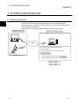
Product Makeup
GX RemoteService-I are made up of the following products.
Product Name
GX RemoteService-I Version1 (1-license product)
SW1D5C-RAS-E
1
License agreement
Software registration Card
1
End-user software license agreement
1
GX RemoteService-I Version1 (Multiple license product)
SW1D5C-RAS-EA
Quanity
1 (CD-ROM)
1 (CD-ROM)
1
License agreement
Software registration Card
n 1
End-user software license agreement
1
1: The same number of software registration card as that of license are packed with the product.
A-9
A-9
1 OVERVIEW
MELSOFT
1. OVERVIEW
1
1.1 Features
GX RemoteService-I allows you to monitor/diagnose the PLC CPU status (read
devices and comments) from a remote location using the Internet.
1-1
1-1
1 OVERVIEW
MELSOFT
(1) PLC CPU can be monitored/diagnosed via the Internet
The personal computer allows you to know the PLC status.
1
(2) This system can be introduced without any modification to the
existing system
No dedicated special modules are required to use this product.
In addition, you need not change the parameter values since this product does
not require I/O points.
(3) Wizard ensures ease of various settings
Using the Wizard for settings, you can easily set the following items necessary
for the server (personal computer).
Setting items
• e-mail setting
• Dialup setting
• PLC type setting
• Connection setup
• Device range setting
• Tag setting
• Automatic operation setting
• Device display format setting
1-2
1-2
1 OVERVIEW
MELSOFT
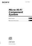
1.2 About Automatic Operation and Manual Operation
GX RemoteService-I allows you to select the automatic or manual operation mode.
The features of the automatic and manual operation modes are explained below. They
will be helpful for you when constructing a system.
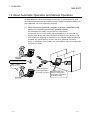
(1) When the server (personal computer) is always connected to the
system for monitoring (automatic operation mode)
GX RemoteService-I always monitors the PLC CPU devices.
If a fault has occurred in the system, GX RemoteService-I connects with the
Internet automatically and informs the personal computer of the fault by e-mail.
(The condition for triggering the transmission of e-mail that notifies the personal
computer of a system fault is to be set to the server (personal computer).)
Hence, a serviceman can be notified of an error definition within a short time after
occurrence of a fault.
Serviceman
Displays the PLC's device value
and comment/tag by a single click
Internet
Belt conveyor
stopped on line A!
System diagnosis is
enabled by using the
device with comments.
GX RemoteService-I
detects a system error
and notifies a serviceman
by sending e-mail.
Serviceman
1-3
1-3
1 OVERVIEW
MELSOFT
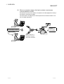
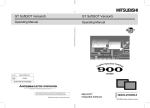
(2) When an operator judges a fault and contacts a serviceman
(manual operation mode)
If a fault has occurred in the system, an operator can make judgment to notify a
serviceman of the faulty condition.
The serviceman can diagnose the actual system from a remote location to run
more in-depth diagnostics.
Serviceman
Displays the PLC's device value
and comment/tag by a single click
Operator
sends e-mail
to serviceman.
Internet
Belt conveyor
stopped on line A!
Operator
System diagnosis is
enabled by using the
device with comments.
Serviceman
1-4
1-4
2 SYSTEM CONFIGURATION
MELSOFT
2. SYSTEM CONFIGURATION
2.1 System Device List
2
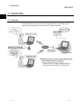
This section explains the system configuration that uses GX RemoteService-I.
Refer to Section 2.1.1, Section 2.1.2 and Section 2.1.3 for the system device lists of
the server (personal computer).
Refer to Section 2.2.2 for the system device list of the personal computer.
Personal computer side
Server (personal computer) side
Personal computer
Internet
The following environment is required for the personal computer.
1. You need to make a contract with a provider.
(Dialup connection)
Mobile phone
Refer to Section 2.2.2.
2. Applications that must be installed into the server
(personal computer)
(1) GX RemoteService-I
(2) Web server software
Personal Web Server 4.0 (PWS4.0) : Windows 98/
Windows NT 4.0
Internet Information Server (IIS5.0) : Windows 2000
R
R
R
Refer to Section 2.1.1.
Refer to Section 2.1.2.
Refer to Section 2.1.3.
Refer to Section 2.2.1.
2-1
2-1
2 SYSTEM CONFIGURATION
MELSOFT
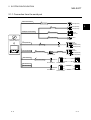
2.1.1 Connection from the serial port
USB communication
1
QCPU(Qmode)
USB cable
2
QC30R2
QCPU(Qmode)
QCPU(Amode)
Converter/cable
ACPU
QnACPU
3
Serialport communication
3
Converter/cable
GX RemoteService-I
(SW1D5C-RAS-E)
FXCPU
4
Computer link
5
RS-232C
C24
CC-Link (via G4)
3
Converter/cable
CC-Link
ACPU
QnACPU
QCPU(Qmode)
QCPU(Amode)
G4module
G4-S3 module
MELSECNET(||)
ACPU
QnACPU
QCPU(Qmode)
QCPU(Amode)
3
Converter/cable
Remote station
Remote module
Master station
Remote sation
Remote module
Control station
MELSECNET/10
MELSECNET/H
2-2
2-2
2
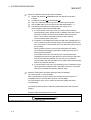
2 SYSTEM CONFIGURATION
MELSOFT
1: About the USB cable (QCPU (Q mode) compatible)
(1) Usable with Windows 98/ME/2000 when the USB driver has been
installed.
(2) Unusable for Windows 95, WindowsNT 4.0.
(3) Use of the USB cable allows only one PLC CPU to be connected.
(4) Use the UBS cable which conforms to the USB Standard Rev. 1.1.
(5) The following indicates the precautions for and restrictions on
communications made using the USB cable.
1) A communication error may occur if you set the resume function,
suspend setting, power saving function or standby mode of the server
(personal computer) to make communications with the PLC CPU.
Hence, do not set any of the above functions when making
communications with the PLC CPU.
2) Frequently connecting/disconnecting the USB cable, resetting the PLC
CPU or switching power OFF/ON during communications with the PLC
CPU may cause a communication error from which the system may not
be recovered.
Where possible, therefore, exit from GX RemoteService-I before
connecting/disconnecting the USB cable, resetting the PLC CPU or
switching power OFF/ON.
If the system cannot be recovered from the communication error,
completely disconnect the USB cable once and reconnect it after more
than five seconds have elapsed. (An error may occur at the first
communication after this operation, but the system will function properly
after the second time and later.)
3) A communication error may occur depending on the combination of the
server (personal computer) model, USB cable and others. In that case,
refer to the messages and perform operation again.
R
R
R
2: About the cable (QCPU (Q mode), QCPU(A mode) compatible)
For communication in 115.2/57.6kbps
Fast communication cannot be made if the Personal computer used is not
compatible with the communication speed of 115.2/57.6kbps.
If a communication error occurs, reduce the baud rate setting and restart
communication.
The following cable has been confirmed by Mitsubishi Electric that it will work
properly.
Using the cable of Mitsubishi Electric make
RS-232 cable
QC30R2 (when Personal computer connector is D-sub, 9-pin)
2-3
2-3
2 SYSTEM CONFIGURATION
MELSOFT
3: About the converter/cable (ACPU, QnACPU, FXCPU compatible)
(1) Using the products of Mitsubishi Electric make.
RS-232 cable
For ACPU, QnACPU, FX1/FXU, FX2CCPU
FX-422CAB (0.3m)
F2-232CAB-1
FX-422CAB-150 (1.5m)
(when Personal
computer connector is D-
FX-232AW(C)
For FX0/FX0S/FX0N/FX1S/FX1N/FX2N/FX2NCCPU
sub, 9-pin)
FX-422CABO (1.5m)
• How to identify compatibility of the F2-232CAB and F2-232CAB-1 cables with the
ACPU and QnACPU
Check the indication of the model label attached to the cable.
Incompatible products
Compatible products (with indication of F/FX/A)
F2-232CAB
Y990C
F2-232CAB(F/FX/A)
Y990C
F2-232CAB-1
Y990C
F2-232CAB-1(F/FX/A)
Y990C
4: About the modems relayed
Use the straight cables supplied with the modems.
5: About computer link
For the RS-232C cable, refer to the GX Developer Operating Manual.
2-4
2-4
2 SYSTEM CONFIGURATION
MELSOFT
2.1.2 Connection from the interface boards
The following system configuration is made up by connection from the interface
boards.
Refer to the corresponding board manuals for the way to connect the boards and
install the drivers.
1
MELSECNET/10 board
A70BDE-J71QLP23
(Optical loop)
A70BDE-J71QLP23GE
(Optical loop)
A70BDE-J71QBR13
(Coaxial bus)
A70BDE-J71QLR23
(Coaxial loop)
Driver
SW3DNF-MNET10
ACPU
QnACPU
QCPU(Q mode)
QCPU(A mode)
Other satation PLC
MELSECNET/H board
Q80BD-J71BR11
(Coaxial bus)
Q80BD-J71LP21-25
(Optical loop)
Q80BD-J71LP21G
(Optical loop)
Q80BD-J71LP21GE
(Optical loop)
Driver
SW0DNC-MNETH-B
ACPU
QnACPU
QCPU(Q mode)
QCPU(A mode)
Other satation PLC
2
CC-Link board
GX RemoteService-I
(SW1D5C-RAS-E)
Driver
A80BDE-J61BT11
A80BDE-J61BT13
SW4DNF-CCLINK-B
ACPU
QnACPU
QCPU(Q mode)
QCPU(A mode)
Other satation PLC
3
Ethernet board
Driver
Commercially Ethernet board
Driver supplied with
commercially available
Ethernet board
ACPU
QnACPU
QCPU(Q mode)
QCPU(A mode)
Other satation PLC
CPU board
Driver
SW1DNF-ANU-B
A80BDE-A2USH-S1
4
SSCNET board SSCNET board
Driver
A30BD-PCF
Motion Controller
(SCPU)
A30CD-PCF
Other station PLC
2-5
2-5
2 SYSTEM CONFIGURATION
MELSOFT
1: MELSECNET/10 board
The following table indicates the drivers that cannot be used with the specific
Operating Systems.
Driver Name
SW3DNF-MNET10
SW0DNC-MNETH-B
Operating Systems
Cannot be used with Windows
R
Me/2000.
Cannot be used with Windows
R
Me.
If a communications error takes place, an error code is indicated in the least
significant 4 digits.
Refer to the error code list of the MELSECNET/10 board manual.
2: CC-Link board
The A80BDE-J61BT11 allows setting of the master/local station.
The A80BDE-J61BT13 is accessible only when local station setting has been
made.
3: Ethernet board
(1) The following Ethernet boards/cards have been confirmed by Mitsubishi
Electric to operate properly.
Maker Name
Model
3COM make
Ethernet Link III LAN PC Card
Allied Telesis make
Center COM LA-PCM Ethernet PC
Card LAN Adapter
Ethernet board/card
TDK make
10BASE-T LAN card
Allied Telesis make
RE2000 (ISA)
(Model: LAN-CD021BX)
Ethernet board
4: SSCNET board/card
Use the personal computer where Windows NT 4.0 (Service Pack 2) or later
has been installed.
R
2-6
2-6
2 SYSTEM CONFIGURATION
MELSOFT
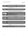
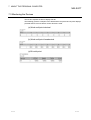
2.1.3 System equipment lists
(1) The following list indicates module connectable from the serial port.
PC Series
Module Name
PLC CPU module
Module Model
Q00J, Q00, Q01, Q02(H), Q06H, Q12H, Q25H
Q02(H)-A, Q06H-A
Q Series
Serial communication module 1
QJ71C24, QJ71C24-R2
MELSECNET/H network remote I/O module
QJ72LP25, QJ72BR15
G4-S3 module
AJ65BT-G4-S3
PLC CPU module
Q2A, Q2AS(H), Q2AS1, Q2AS(H)S1, Q3A, Q4A, Q4AR
AJ71QC24, AJ71QC24-R2, AJ71QC24-R4,
Serial communication module 2
AJ71QC24N, A1SJ71QC24, A1SJ71QC24-R2,
AJ71QC24N-R2, AJ71QC24N-R4, A1SJ71QC24N,
A1SJ71QC24N-R2
QnA Series
MELSECNET/10 network remote I/O module
AJ72QLP25, AJ72QBR15, A1SJ72QLP25,
A1SJ72QBR15
G4 module
AJ65BT-G4
G4-S3 module
AJ65BT-G4-S3
A0J2H, A1S(S1), A1FX, A1SJ, A1SH, A1SJH, A1N,
PLC CPU module
A2C, A2CJ, A2N(S1)A2S(S1), A2SH(S1), A3N,
A2A(S1), A3A, A2U(S1), A2AS(S1), A2AS-S30,
A2AS-S60, A3U, A4U
AJ71UC24, A1SJ71UC24-R2,
Computer link module 3
A Series
A1SJ71UC24-PRF, A1SJ71C24-R2, A1SJ71C24-PRF,
AJ71C24-S6, AJ71C24-S8, A1SCPUC24-R2,
A2CCPUC24, A2CCPUC24-PRF
MELSECNET(II) data link remote I/O module
FX Series
MOTION
(SCPU)
2-7
AJ72P25, AJ72R25
MELSECNET/B data link remote I/O module
AJ72T25B, A1SJ72T25B
MELSECNET/10 data link remote I/O module
AJ72LP25, AJ72LP25, AJ72BR15
G4 module
AJ65BT-G4
G4-S3 module
AJ65BT-G4-S3
PLC CPU module
FX0(S), FX0N, FX1, FXU, FX2C, FX1S, FX1N, FX1N, FX2N(C)
PLC CPU module
A171SH, A172SH, A173UH(S1), A273UH(S3)
2-7
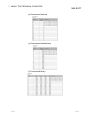
2 SYSTEM CONFIGURATION
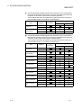
MELSOFT
(2) The following table indicates the modules which can be connected from the USB
PC Series
Q Series
Module Name
Module Model
PLC CPU module
Q02H, Q06H, Q12H, Q25H
(3) The following table indicates the modules which can be connected from the
MELSECNET/H board.
PC Series
Q Series
Module Name
QJ71LP21, QJ71BR11, QJ71LP21-25
(4) The following table indicates the modules which can be connected from the
MELSECNET/10 or MELSECNET/H (MELSECNET/10 mode) board.
PC Series
Q Series
Module Name
QJ71LP21, QJ71BR11
QJ71LP21, QJ71BR11, QJ71LP21-25
QnA Series
AJ71QLP21, AJ71QBR11, A1SJ71QLP21, A1SJ71QBR11
A Series
AJ71LP21, AJ71BR11, A1SJ71LP21, A1SJ71BR11
(5) The following list indicates modules connectable from the CC-Link board.
PC Series
Q Series
Module Name
QJ61BT11
QnA Series
AJ61QBT11, A1SJ61QBT11
A Series
AJ61BT11, A1SJ61BT11
(6) The following list indicates modules connectable from the Ethernet board.
PC Series
Module Name
Q Series
QJ71E71, QJ71E71-B2, QJ71E71-100
QnA Series
AJ71QE71, AJ71QE71-B5, A1SJ71QE71-B2, A1SJ71QE71-B5
A Series
AJ71E71-S3, A1SJ71E71-B2-S3, A1SJ71E71-B5-S3, A1SJ71E71-B2, A1SJ71E71-B5
(7) The following table indicates the modules which can be connected from the
SSCNET board
PC Series
MOTION(SCPU)
2-8
Module Name
A171SH, A172SH, A173UH(S1), A273UH
2-8
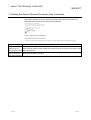
2 SYSTEM CONFIGURATION
MELSOFT
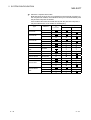
1: The following table indicates whether the interfaces may be connected to
the personal computer when the PLC CPU is accessed from the personal
computer via the serial communication module (Q series).
If the module cannot be connected directly with the personal computer, it
may be usable as the "n"th module of multidropping.
Type
QJ71C24
QJ71C24-R2
Interface
1:1
Connection
Multidropping
First module
"n"th module
RS-232C
RS-422/485
RS-232C
RS-232C
2: The following table indicates whether the interfaces may be connected to
the personal computer when the PLC CPU is accessed from the personal
computer via the serial communication module (QC24).
If the module cannot be connected directly with the personal computer, it
may be usable as the "n"th module of multidropping.
Type
AJ71QC24
AJ71QC24N
AJ71QC24-R2
AJ71QC24N-R2
AJ71QC24-R4
AJ71QC24N-R4
A1SJ71QC24
A1SJ71QC24N
A1SJ71QC24-R2
A1SJ71QC24NR2
2-9
Interface
1:1
Connection
Multidropping
First module
"n"th module
RS-232C
RS-422/485
RS-232C
RS-422/485
RS-232C
RS-232C
RS-232C
RS-232C
RS-422
RS-422/485
RS-422
RS-422/485
RS-232C
RS-422/485
RS-232C
RS-422/485
RS-232C
RS-232C
RS-232C
RS-232C
2-9
2 SYSTEM CONFIGURATION
MELSOFT
3: About the computer link module
Note that when the PLC CPU is accessed from the personal computer via
the computer link module, the modules that may be connected directly with
the personal computer are limited.
If the module cannot be connected directly with the personal computer, it
may be usable as the "n"th module of multidropping.
Type
AJ71UC24
AJ71C24-S6
AJ71C24-S8
Interface
1:1
Connection
Multidropping
First module
"n"th module
RS-232C
RS-422/485
RS-232C
RS-422
RS-232C
RS-422
A1SJ71UC24-R2
RS-232C
A1SJ71C24-R2
RS-232C
A1SJ71UC24PRF
RS-232C
A1SJ71C24-PRF
RS-232C
A1SJ71UC24-R4
RS-422/485
A1SJ71C24-R4
RS-422/485
A1SCPUC24-R2
RS-232C
RS-232C
A2CCPUC24
RS-422
RS-422/485
RS-232C
A2CCPUUC24PRF
RS-422
RS-422/485
2 - 10
2 - 10
2 SYSTEM CONFIGURATION
MELSOFT
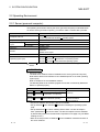
2.2 Operating Environment
2.2.1 Server (personal computer)
The operating environment used by the server (personal computer) is indicated below.
To use the server (personal computer), you need to make a contract with a provider.
Item
Description
Pentium
Computer main unit
R
200 MHz or faster (recommended) based personal computers
that are compatible with Windows
Required memory
R
operating system
64MB or more (recommendation)
Required hard disk
For installation
100 MB or more
space
For operation
100 MB or more
Disk drive
CD-ROM drive
Resolution
Monitor
800x600 dot or higher
Modem
Modem that can be connected to the provider
Operating system (OS)
: Windows
server.
R
Microsoft
R
Windows
Microsoft
R
WindowsNT
Microsoft
R
Windows
R
R
98 Second Edition Operating System
R
Workstation 4.0 Operating System
2000 Professional Operating System
Me cannot be used with this product since it does not support the PWS
IMPORTANT
1) Required software
The Web server software must be installed into the server (personal computer).
Note that the Web server software to be installed depends on the used operating
system (OS).
Refer to Chapter 5 for the installation method.
The following Web server software programs have been confirmed by Mitsubishi
Electric to operate properly.
Used OS
Microsoft
R
R
Windows
Microsoft
R
WindowsNT
R
Windows
Installed Software
98 Second Edition Oprating System Personal Web Server 4.0
R
Workstation 4.0 Operating
(PWS4.0)
System
Microsoft
R
2000 Professional Operating
System
Internet Information
Server 5.0(IIS5.0)
• Any server software other than the above is unusable.
• Set up Windows 98 or Windows 2000 when installing the operating system
(OS).
• Set up WindowsNT 4.0 when installing Service Pack 3 or later and Option
Pack. (WindowsNT 4.0 Service Pack 3 or later and Option Pack are available
by downloading them from the Microsoft Corporation home page or by CD-ROM
sending service.)
• Refer to the help function of Windows for the installation method and others of
the server software.
R
R
R
R
R
2 - 11
2 - 11
2 SYSTEM CONFIGURATION
MELSOFT
2) Contract with provider
Prepare a server (personal computer) that can browse home pages and send
e-mail.
3) Dialup connection
You must dial up your provider to connect with the Internet.
2.2.2 Personal computer
The necessary environment is as follows.
Used Device
Description
When using a personal
Personal computer where the Web browser has been installed
computer.
(Microsoft Corporation's Internet Explorer 4.0 or later or Netscape
When using a mobile
Communication Corporation's Netscape Communicator 4.0 or later)
i mode compatible mobile phone
J-Sky compatible mobile phone
phone.
R
Ezweb compatible mobile phone
:This product can be used only in Japan.
! You need to make a contract with a provider.
2 - 12
2 - 12
3 FUNCTION LIST
MELSOFT
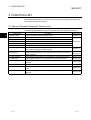
3. FUNCTION LIST
This chapter lists the items to be set on the server (personal computer) and the items
to be set on the personal computer.
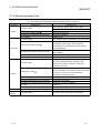
3.1 Server (Personal Computer) Function List
The following table lists the functions to be set on the server (personal computer).
Function Name
3
Description
Operating mode
Sets the automatic or manual operation mode.
Starts AUTO run
Starts the continuous monitoring of devices in the automatic operation mode.
Dial up execute
Makes dialup connection to connect with the Internet.
URL copy
Copies the URL of the server (personal computer).
Send e-mail
Sends e-mail created with GX RemoteService-I.
Product information
Displays the version and others of the product.
E-mail setting
Makes settings related to e-mail (mail server, account name, etc.).
Also creates a message for manual operation.
Dial up setting
Selects the dialup connection name. Also selects the method for terminating
dialup connection.
PLC type selection
Reference
Section 6.1
Section 6.2
Section 6.3.1
Section 6.3.2
Selects the PLC type of the PLC to be monitored on the personal computer.
Section 6.3.3
Transfer setup
Selects the path of the PLC to be monitored on the personal computer.
Section 6.3.4
Device range setting
Makes settings related to the device to be monitored on the personal
computer.
Tag setting
Makes setting for handling the read devices as tags.
Auto run setting
Sets the device to be monitored continuously in the automatic operation
mode.
Dev. disp. setting
Changes the display format of the screen displayed on the personal
computer.
3-1
Section 6.3.5
Section 6.3.6
Section 6.3.7
Section 6.3.8
3-1
3 FUNCTION LIST
MELSOFT
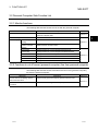
3.2 Personal Computer Side Function List
3.2.1 Monitor functions
The following table lists the functions to be set with the personal computer.
Reference
Description
Tag display
Performs one-shot monitoring of the tag set on the server
(personal computer) side.
Transfer setup
Device display
Reference
Section 7.2
3
Sets the PLC series, PC side I/F, PLC side I/F and other station.
Device range
Sets the device to be monitored.
Section 7.1
setting
Device comment
Makes a device comment search.
search
Word (Dec)
Displays devices in a word multi-point decimal format.
Word (Hex)
Displays devices in a word multi-point hexadecimal format.
Bit
Displays devices in a bit multi-point format.
Comment Dec
Displays devices in a commented decimal format.
Comment Hex
Displays devices in a commented hexadecimal format.
Comment Bin
Displays devices in a commented binary format.
Section 7.3
3.2.2 Functions to cut off server (personal computer) line from personal computer
The following table lists the functions that disconnect the server (personal computer)
line from the personal computer.
Reference
Server Side Circuit Settings Time to
Description
Sets the server (personal computer) line disconnection timer.
disconnect the circuit
Server Side dialup disconnect
Reference
Disconnects the server (personal computer) line.
Section 7.4
execution
3-2
3-2
4 PRE-OPERATION SETTINGS AND PROCEDURES
MELSOFT
4. PRE-OPERATION SETTINGS AND PROCEDURES
This chapter explains the setting items and procedures necessary for the server
(personal computer) and personal computer.
Personal computer side
(See Section 4.2)
Server (personal computer) side
(See Section 4.1)
Personal computer
Internet
4
Mobile phone
4-1
4-1
4 PRE-OPERATION SETTINGS AND PROCEDURES
MELSOFT
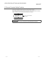
4.1 Server (Personal Computer) Setting Procedure
This section explains the procedure for setting the server (personal computer).
Start
Sign-up for provider
Installation and setting
of dialup network
Installation and setting of browser
Installation of e-mail software
Installation and setting of
GX RemoteService-I
Before installing GX RemoteService-I and
Web server software, prepare the server
(personal computer) where e-mail and
Internet have been confirmed to operate properly.
Refer to the data packed.
E-mail setting
Send mail (SMTP) server
Send mail (POP3) server
Account name
Password
E-mail address
SendTo setting
Refer to Section 6.3.1.
Dial up setting
Dial up setting
Auto circuit disconnection method
Enable disconnection of dial up
connection on client side
Refer to Section 6.3.2.
PLC type selection
PLC type series
PLC type selection
Refer to Section 6.3.3.
Transfer setup
PC side I/F
PLC side I/F
Other station
Network route
Refer to Section 6.3.4.
Device range setting
Device
Points
Program
Target memory
Comment date
Comment type
Refer to Section 6.3.5.
Tag setting
Tag name
Index
Set each device of the tag
Refer to Section 6.3.6.
4
1)
4-2
4-2
4 PRE-OPERATION SETTINGS AND PROCEDURES
MELSOFT
1)
When manual operation mode is selected
Auto run setting
Monitor time interval
Watch
Trigger condition
Subject of message
SendTo setting
Refer to Section 6.3.7.
Dev.disp.setting
Bit device display format
Monitor screen display format
Refer to Section 6.3.8.
Installation of Web server software
Refer to Chapter 5.
End
4-3
4-3
4 PRE-OPERATION SETTINGS AND PROCEDURES
MELSOFT
4.2 Personal Computer Setting Procedure
This section explains the items to be set on the personal computer.
When making access from the personal computer to the server (personal computer),
make a contract to use the Internet with the personal computer.
Start
Make a contract to use
the Internet.
Make a contract according to
the provider.
End
POINT
Refer to Section 2.2.2 for the environment of the usable personal computer.
4-4
4-4
5 INSTALLATION OF WEB SERVER SOFTWARE
MELSOFT
5. INSTALLATION OF WEB SERVER SOFTWARE
For the installation and uninstallation operations of this product (GX RemoteService-I),
refer to "How to Install the MELSOFT Series" packed with the utility package.
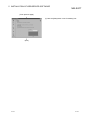
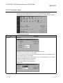
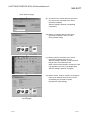
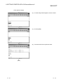
5.1 Windows 98
R
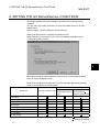
The following indicates how to set up the Web server.
(Start)
(1) Set the CD-ROM included with the used server
(personal computer) into the CD-ROM drive and
execute C:\add-ons\pws\Setup.exe.
If the above file is not found on the CD-ROM, the
installer is stored in\Windows\Options\Cabs
\Pws in the drive where Windows 98 has been
installed. (Screen shown on the left)
R
5
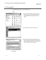
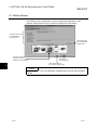
(2) Start the Web server (Personal Web Server 4.0).
(3) As the screen on the left appears, click [Advanced].
(To next page)
5-1
5-1
5 INSTALLATION OF WEB SERVER SOFTWARE
MELSOFT
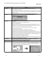
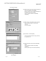
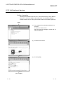
(From previous page)
(4) Choose Home from the virtual list and click the
[Add] button.
(5) As the Add Directory dialog box appears, make the
following settings.
1) Directory:
Specify "C:\MELSEC\RAS\home\index". (Specify
a new folder when you changed the installation
destination folder at the installation of GX
RemoteService-I.)
2) Alias: Enter "INDEX".
3) Access: Enable "Read" and "Scripts".
(6) An alias (INDEX) is added to the virtual directory.
Click [Main] after confirming that the alias has been
added.
(To next page)
5-2
5-2
5
5 INSTALLATION OF WEB SERVER SOFTWARE
MELSOFT
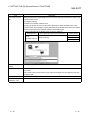
(From previous page)
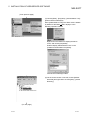
(7) Click the [Start] button in the "Publishing" list.
(End)
POINT
If you have added the alias with Web issue ON, stop Web issue once and click the
[Start] button again to turn Web issue ON.
5-3
5-3
5 INSTALLATION OF WEB SERVER SOFTWARE
MELSOFT
5.2 Windows NT 4.0
R
The following indicates how to set up the Web server.
(Start)
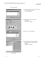
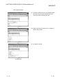
(1) Set Option Pack into the CD-ROM drive and
double-click setup.exe.
Installation starts.
(2) Choose [Program] - [Windows NT 4.0 Option Pack]
- [Microsoft Personal Web Server] - [Personal Web
Manager].
(3) As the screen on the left appears, click [Advanced].
(To next page)
5-4
5-4
5 INSTALLATION OF WEB SERVER SOFTWARE
MELSOFT
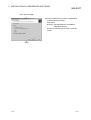
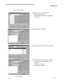
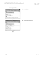
(From previous page)
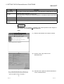
(4) Choose Home from the Virtual list and click the
[Add] button.
(5) As the Add Directory dialog box appears, make the
following settings.
1) Directory:
Specify "C:\MELSEC\RAS\home\index". (Specify
a new folder when you changed the installation
destination folder at the installation of GX
RemoteService-I.)
2) Alias: Enter "INDEX".
3) Access: Enable "Read" and "Scripts".
(6) An alias (INDEX) is added to the virtual directory.
Click [Main] after confirming that the alias has been
added.
(To next page)
5-5
5-5
5 INSTALLATION OF WEB SERVER SOFTWARE
MELSOFT
(From previous page)
(7) Click the [Start] button in the "Publishing" list.
(End)
5-6
5-6
5 INSTALLATION OF WEB SERVER SOFTWARE
MELSOFT
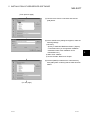
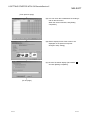
5.3 Windows 2000
R
The following indicates how to set up the Web server.
(Start)
(1) Set the CD-ROM included with the used server
(personal computer) into the CD-ROM drive and
open [Add/Remove Programs] from [Control
panel].
(2) Click Add/Remove Windows Components.
(3) Since the Windows Components Wizard screen
starts, enable [Internet Information Service (IIS)]
and click [Next]. (Installation starts. Installation ends
when the completion screen appears.)
(To next page)
5-7
5-7
5 INSTALLATION OF WEB SERVER SOFTWARE
MELSOFT
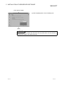
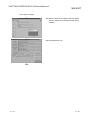
(From previous page)
(4) Choose [Start] - [Programs] - [Administrative Tool] [Internet Services Manager].
Since [Administrative Tool] in the Start menu is hidden
by default on Windows 2000, display it in the
following operation method.
R
Right-click on the taskbar to display the above
menu, and choose [Properties].
Enable "Display Administrative Tools" in the
[Taskbar and Start Menu Properties].
Internet Service Manager starts.
(5) On the screen shown on the left, choose [Default
Web Site] and right-click to choose [New] - [Virtual
Directory].
(To next page)
5-8
5-8
5 INSTALLATION OF WEB SERVER SOFTWARE
MELSOFT
(From previous page)
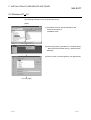
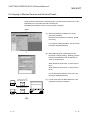
(6) Since Virtual Directory Creation Wizard starts,
make the following settings.
Alias: Index
Directory: GX RemoteService-I installation
destination directory
Set Access Permissions as shown on the left
screen.
(End)
5-9
5-9
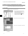
6 SETTING THE GX RemoteService-I FUNCTIONS
MELSOFT
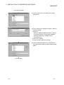
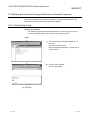
6. SETTING THE GX RemoteService-I FUNCTIONS
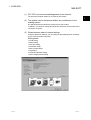
This chapter explains the function settings to be made on the server (personal
computer).
You may make each setting as desired, but using the Wizard allows you to make
settings easily.
Refer to Chapter 4 for the setting items and procedures.
Starting GX RemoteService-I displays the following screen.
Refer to Section 6.2 and Sections 6.3.1 to 6.3.8 for detailed explanation of the
corresponding setting screens.
6
Select the automatic or manual operation mode and then click the [Setting wizard]
button to display the Wizard screen.
Whether the setting items must be set or not in the automatic and manual operation
modes is as indicated in the following table.
manual operation mode
Setting Item
automatic operation modes
When e-mail function of When mail software
GX RemoteService-I is such as Microsoft
used
R
Outlook Express is used
E-mail setting
Dial up setting
PLC type selection
Transfer setup
Device range setting
Tag setting
Auto run setting
Dev. disp. setting
: Setting required
: Setting not required
6-1
6-1
6 SETTING THE GX RemoteService-I FUNCTIONS
MELSOFT
6.1 Setting Wizard
The following screen is displayed by clicking the [setting wizard] button on the
operation mode selection screen. Follow the messages to make setting.
The check mark moves
in accordance with
the setting item.
Click here to open
the corresponding
setting screen.
The focus moves to
the item to be set to
indicate which is being set.
Click here to
set the next item.
Click here to return to
the previous setting screen.
6
POINT
Refer to Section 6.3 for the explanation of detailed items to be set with the Setting
Wizard.
6-2
6-2
6 SETTING THE GX RemoteService-I FUNCTIONS
MELSOFT
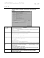
6.2 Main Screen
This section explains the server URL, dialup execution, e-mail send and other
functions.
Item
Server URL
Description
Shows the URL with the IP address.
Shows "---.---.---.---" instead of the IP address if the IP address assigned by the Internet service
provider cannot be acquired.
This product cannot be used when the IP address is not displayed.
Log information
Shows error definition in the automatic operation mode.
• Shows the errors and operation of the personal computer.
• Shows the time and date.
• The log can be copied in the selected range.
• The log is up to 100 lines long. If it exceeds 100 lines, the older lines are deleted in due order.
Clear log
Clears the message in log information.
Dail up time
Shows the elapsed time after dialup execution.
The time is updated at intervals of five seconds.
"--:--:--" appears if:
• Dialup is not executed; or
• Dialup is executed from other than GX RemoteService-I.
If the time has exceeded 9999:59:59 (9999 hours 59 minutes 59 seconds), it returns to 00:00:00.
Dail up disconnection
Appears when the automatic line disconnection system is access time monitoring or dialup
time
disconnection timer in the line disconnection setting. ("--:--:--" appears if the setting is not made.)
Counts down to zero.
The time is updated at intervals of five seconds.
For access time monitoring, countdown starts from the preset time every time access is made.
The line is disconnected when the time is zeroed.
Starts auto run
Always executes monitoring.
The button name changes to "stop auto run" during automatic operation, and clicking it
terminates the automatic operation.
6-3
6-3
6 SETTING THE GX RemoteService-I FUNCTIONS
Item
MELSOFT
Description
Dial up execute
Starts dialup connection with the preset connection name (this button is masked when the dialup
connection name is not yet set).
URL copy
Copies the address displayed in the Server URL.
When sent from the e-mail function of GX RemoteService-I, the address is added to the mail text
automatically.
Send e-mail
Sends e-mail to the preset send destination.
Product information
Displays the version of the product.
Return to mode
selection
Returns to the automatic operation mode/manual operation mode selection screen.
REMARK
The following gives a procedure for sending in the manual operation mode using the email software such as Microsoft Outlook Express.
R
(Start)
(1) Start the mail software and create a mail text.
(2) Click the "URL copy" button on GX
RemoteService-I.
(3) Paste the URL copied from GX RemoteServiceI to the created mail text.
6-4
6-4
6 SETTING THE GX RemoteService-I FUNCTIONS
MELSOFT
6.3 Setting the Server (Personal Computer) Functions
6.3.1 E-mail setting
Set as required since the items to be set differ between the automatic and manual
operation modes.
We recommend you to read "Description for Use" or like sent from the provider to
make settings.
Item
Description
Send mail (SMTP)
Specify the server to be used when sending e-mail from GX RemoteService-I.
server
Set the address supplied by the provider.
Number of acceptable characters: 1 to 256 characters
Send mail (POP3)
Enter the server to be used when receiving e-mail.
server
Set the address supplied by the provider.
Number of acceptable characters: 1 to 256 characters
Account name
Specify the account name for POP3 server authentication.
Set the account name supplied by the provider.
Number of acceptable characters: 1 to 255 characters
Password
Specify the password of the account name for POP3 server authentication.
Set the password of the account name supplied by the provider.
Number of acceptable characters: 1 to 255 characters
E-mail address
Specify the returning mail address.
You can set 1 to 255 characters.
Note: Though GX RemoteService-I does not have the function to receive e-mail, set this address
since it is needed when sending e-mail.
Subject of message
Set the subject of e-mail.
Number of acceptable characters: 1 to 256 characters
Note: All the subject may not be displayed depending on the model used.
6-5
6-5
6 SETTING THE GX RemoteService-I FUNCTIONS
Item
Body of message
MELSOFT
Description
Enter the text of e-mail. Number of acceptable characters: 0 to 256 characters
Since the URL of the server is added to the character string sent actually, create a message in
consideration of the number of URL characters.
Description
"SendTo setting"
You can set the send destination in the manual mode only.
button
Item
Description
SendTo e-mail
address
Set the e-mail address of the personal computer.
Set it within the range 1 to 255 characters.
Remarks
Can be used to make a memo of a company name, person's name and like.
Enter them within 256 characters.
Mail
Can be set in the manual operation mode only.
Set whether e-mail will be sent or not.
In the automatic operation mode, the status set for automatic operation setting
appears.
watch 1 to watch 10
Can be set in the automatic operation mode only.
Set whether the system will be monitored or not in the automatic operation
detail setting.
"Copy" button
Used to copy the selected row.
To choose the row, click any of numbers 1 to 20.
You cannot copy the row unless the whole row is selected.
"Paste" button
Used to paste the copied row.
"Delete" button
Used to delete the selected row.
To choose the row, click any of numbers 1 to 20.
You cannot delete the row unless the whole row is selected.
"All clear" button
Used to delete all rows.
E-mail SendTo
Mail
: Select whether e-mail will be sent or not.
specification during
Can be set in the manual operation mode only.
manual run
SendTo e-mail address
: Shows the e-mail send destination.
Remarks
: You can set the additional information on the e-mail send
destination.
Use mail send of GX
RemoteService-I
6-6
Can be selected in the manual operation mode.
Automatically set in the automatic operation mode.
6-6
6 SETTING THE GX RemoteService-I FUNCTIONS
MELSOFT
6.3.2 Dialup setting
This section explains the dialup setting.
Item
Description
Dial up connection
Select the connection name set in the dialup setting.
name
The number of displayed characters is up to 16.
Redial
Count: Set within 0 to 99.
Interval: Set within 0 to 999.
Access timer watch
Disconnects the dialup connection if there is no access to the server (personal computer) for a
predetermined period of time.
Hour: Set within 0 to 99.
Minutes: within 0 to 59.
Note that you cannot set 0 hours 0 minutes.
Dial up disconnection
Disconnects the dialup connection in a predetermined period of time.
timer
Hour: Set within 0 to 99.
Minutes: within 0 to 59.
Note that you cannot set 0 hours 0 minutes.
Enable dial up
Set whether or not the line disconnection timer can be set again from the personal computer.
disconnection timer
Made valid only when the line disconnection timer has been selected.
setting on client side
Enable disconnection
Enables the dialup connection of the server (personal computer) to be made by the personal
of dial up connection
computer.
on client side
With the exception of the personal computer that has disconnected the line, the line is
disconnected without previous notice to disable communication with the server (personal
computer).
6-7
6-7
6 SETTING THE GX RemoteService-I FUNCTIONS
MELSOFT
6.3.3 PLC type setting
As the PLC type, set the PLC series and PLC type of the PLC to be accessed first from
the personal computer.
Item
Description
PLC series
Set the items when selecting or changing the PLC Series and/or PLC type of the PLC to be
PLC type
accessed first from the personal computer.
PLC series
ACPU
PLC type
AnN, AnA, AnS, AnSH
Remark
A0J2H, A1FX, A1S, A1SJ, A1SH,
A1SJH, A1N, A2C, A2CJ, A2N(S1),
A2S, A2SH, A3N, A2A(S1), A3A
AnU, A2AS
A2U(S1), A2AS(S1), A2AS-S30,
A2AS-S60, A3U, A4U
QnACPU
QCPU-Q
Qn (H)
SCPU
FXCPU
6-8
Q2AS(H)S1, Q3A, Q4A, Q4AR
Q02(H), Q06H, Q12H, Q25H
Q00J,Q00,Q01
QCPU-A
Q2A, Q2AS(H), Q2AS1,
Q00J, Q00, Q01
Q02(H)-A, Q06H-A
A171SH
A171SH
A172SH
A172SH
A173UH (S1)
A173UH(S1)
A273UH (S3)
A273UH(S3)
FX0(S), FX0N, FX1, FXU, FX2C,
FX1S, FX1N, FX2N(C)
6-8
6 SETTING THE GX RemoteService-I FUNCTIONS
Item
MELSOFT
Description
PLC series
If you have chosen the PLC Series and/or PLC type other than the one currently set, the following
PLC type
dialog box appears for confirmation.
Click the "Yes" button to change the following settings and indications.
• Changes the PLC type.
• Changes the connection setup to the PLC CPU direct-coupled path.
• Changes the device range setting to the default value.
• Changes the tag setting to the default value.
• Changes the automatic operation setting to the default value.
Clicking the "No" button does not change the settings.
6-9
6-9
6 SETTING THE GX RemoteService-I FUNCTIONS
MELSOFT
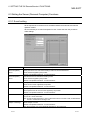
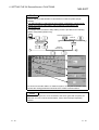
6.3.4 Connection setup
Set the connection setup between the server (personal computer) and PLC.
This setting also specifies the PLC to be accessed first from the personal computer.
(1) Access to the host
Item
PC side I/F
Description
For Q series
• USB may be set only when the QCPU (Q mode) has been selected.
• Precautions for communication at 115.2/57.6kbps
Fast communication cannot be made if the personal computer used is not compatible with the
communication speed of 115.2/57.6kbps.
If communications delay due to communications tries or a communication error occurs, reduce
the baud rate setting and restart communication.
• Precautions for making USB communication
Refer to the GX Developer Operating Manual.
QnA/A/FX series
6 - 10
6 - 10
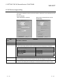
6 SETTING THE GX RemoteService-I FUNCTIONS
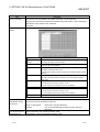
Item
PC side I/F
MELSOFT
Description
• The baud rate that can be selected depends on the PLC Series and PLC type.
• Choose 9.6kbps for the A Series.
• For the QnA Series, the PLC CPU that can communicate at the 38.4kbps speed is the QnACPU
of unction version B or later. Refer to the GX Developer Operating Manual for the way to identify
the module version.
• When using the A6TEL as a converter, refer to the GX Developer Operating Manual.
PLC side I/F
Choose the PLC series of the PLC to be connected with GX RemoteService-I.
Other station
No specification
Specify when the access target is in a multiple PLC system.
Other station (Single network)
It indicates a system which is configured by a single network and a multilevel system, e.g., only
MELSECNET/10 or only Ethernet. (Since Ethernet is regarded as the MELSECNET/10, specify
Single network for an MELSECNET/10 and Ethernet mixed system.)
If a time-out or other error occurs in communications with the PLC CPU, set a longer
communications time check period.
Until the error appears, during execution is displayed in Monitor status.
The longest time until the error appears can be found by the following expression.
(Time specified for communications time check)
3
(Count specified for the number of retries + 1)
For example, when the communications time check is specified as 30 seconds and the number of
retries as 0 times, the resultant time is (30 seconds)
3
(0 + 1) = 90 seconds, and the error
appears after a maximum of 90 seconds have elapsed.
Choose No specification when specifying the own station.
When power-off, hardware reset or the like of the PLC CPU is performed during ladder monitor, it
will take time until a communications error appears.
Network route
Choose the network type, network No., station number and first I/O No. to be accessed.
The setting items depend on the network type that has been set.
Multiple PLC Setting
Specify when the access target is in a multiple PLC system.
Connection channel
You can set the connection target while looking at the Connection channel list.
list
As clicking [OK] automatically sets the connection channel on the Connection Setup screen,
settings can be made easily if a complicated system is configured. Set the network number, station
number and others as desired according to the access target.
Click OK
6 - 11
6 - 11
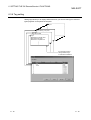
6 SETTING THE GX RemoteService-I FUNCTIONS
Item
MELSOFT
Description
Connection channel
Clicking the [OK] button automatically sets the connection path (area enclosed by a circle) on the
list
Connection setup screen.
About display changing
Convenient use of display selected routes
Specifying the PC side I/F and PLC side I/F and selecting the display selected routes on the
Connection setup screen displays only the paths within the accessible ranges in the other station,
network communication path and mixed network communication path.
A system configuration list of different series can also be displayed.
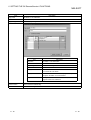
Request Source
Server
(personal computer)
PLC direct coupled
Server (Personal Computer) Connected PLC
Access Target
Q Series
QCPU (Q mode)
QnA Series
A Series
Useful for changing Other station to Host.
setting
Connection test
Tests whether normal access can be made to the access target PLC CPU set on the Connection
setup screen.
When normal access can be made, the type of the access target PLC CPU appears in the CPU
type display field.
System image
Illustrates the set connection target path.
Line connection
Cannot be set.
(Q/A6TEL, C24)
6 - 12
6 - 12
6 SETTING THE GX RemoteService-I FUNCTIONS
MELSOFT
POINT
Screen setting for MELSECNET/10 and Ethernet combined system (Single
network)
In an MELSECNET/10 and Ethernet mixed system configuration, specify Single
network to access the other station. (Since Ethernet is equivalent to the
MELSECNET/10)
An example of the Connection Setup setting screen is provided for the following
system configuration (Q/QnA only).
Request target (Station 1)
Ethernet
Network No.3
MELSECNET/10
Network No.1
Ethernet
Network No.2
For access to the other station or multilevel system, not only the Connection Setup
but also the routing parameters should be set to enable communications.
POINT
When connecting the PLC to be accessed to the server (personal computer) via
Ethernet, CC-Link or serial communication, refer to GX Developer Operating
Manual.
6 - 13
6 - 13
6 SETTING THE GX RemoteService-I FUNCTIONS
MELSOFT
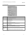
6.3.5 Device range setting
This section explains the name, points and others of the device to be read first from the
PLC CPU.
Screen examples
When Qn(H)CPU is selected
When ACPU is selected (AnU, AnUS,
AnUSHCPU)
Item
Description
Device
Set the device + device No.
Points
Set any of 1, 16, 32, 64, 128 and 256 points.
Program
Set the program name when monitoring the T/C.
Target memory
When you have set the Qn(H)CPU or QnACPU, make selection from the following memories.
You cannot make setting when the set PLC Series is other than the Qn(H)CPU or QnACPU.
Qn(H)CPU
Comment data
QnACPU
Program memory/Device memory
PLC RAM/Device memory
Memory card (RAM)
IC Card A (RAM)
Memory card (ROM)
IC Card A (ROM)
Standard RAM
IC Card B (RAM)
Standard ROM
IC Card B (ROM)
Set the comment data name to be displayed or searched for by the personal computer.
Fixed to "COMMENT" when the set PLC Series is other than the Qn(H)CPU or QnACPU.
Comment type
Set the comment data name to be displayed or searched for by the personal computer.
You need not make setting when the Qn(H)CPU or QnACPU has been set as the PLC Series.
6 - 14
6 - 14
6 SETTING THE GX RemoteService-I FUNCTIONS
MELSOFT
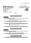
6.3.6 Tag setting
Setting tags allows you to display different devices you want to read (up to 10 device
types) together on the personal computer.
Tag 10
Tag 3
M105 Rotary pump fault
Tag 2
Thermal fault
Tag 1
M100 Robot controller fault
M101 Robot arm fault
M102 Servo amplifier fault
...........
On personal computer,
change between tags
to check device statuses.
6 - 15
6 - 15
6 SETTING THE GX RemoteService-I FUNCTIONS
Item
MELSOFT
Description
Tag name
Set within 1 to 16 characters.
Index
Set within 0 to 64 characters.
Tag setting
Shows the tag setting status.
"Edit" button
Item
Tag name
Description
Set within 1 to 64 characters.
Index
Set within 0 to 64 characters.
Tag setting
Set whether the tag function is made valid or invalid.
Device name
Set the device + device No.
Display
Set decimal or hexadecimal.
You cannot set a bit device.
Display name
Set the device name that will be displayed on the personal
computer. Set within 1 to 32 characters.
Program
When you set the T/C as the device name, set the
program name to be referred to.
"Clear" button
Used to clear the selected tag.
"All clear" button
Used to clear all tags.
6 - 16
6 - 16
6 SETTING THE GX RemoteService-I FUNCTIONS
MELSOFT
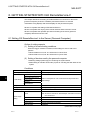
6.3.7 Automatic operation setting
When performing automatic operation, set an e-mail sending trigger condition, an
e-mail message, etc.
Item
Description
Monitor time interval
Set within the range 30 to 9999 seconds.
Index
Set within 0 to 64 characters.
Watch setting
Shows the monitor setting status.
"Edit" button
6 - 17
6 - 17
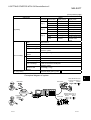
6 SETTING THE GX RemoteService-I FUNCTIONS
Item
MELSOFT
Description
"Edit" button
Item
Description
Watch
Set whether monitoring will be performed or not.
Index
Set within 1 to 64 characters.
Trigger condition
Set the trigger condition for bit or word device.
The following are the condition enabled examples when the
present value of D33 is 100.
Display
=
<
>
<=
>=
<>
Subject of message
Description
Condition is enabled when the value
is equal to 100.
Condition is enabled when the value
is less than 99.
Condition is enabled when the value
is more than 101.
Condition is enabled when the value
is not more than 100.
Condition is enabled when the value
is not less than 100.
Condition is enabled when the value
is other than 100.
Refer to Section 6.3.1.
Body of message
"SendTo setting" button
"Clear" button
Used to delete the selected continuous monitoring setting.
"All clear" button
Used to delete all continuous monitoring settings.
POINT
• If the device set for the trigger condition has already met its condition before a
start of automatic operation, e-mail is sent immediately after automatic operation
is started.
• E-mail is sent when the status of the device set for the trigger condition turns from
OFF to ON.
Note that once e-mail is sent, next e-mail will not be sent until the device status
changes from ON to OFF to ON.
6 - 18
6 - 18
6 SETTING THE GX RemoteService-I FUNCTIONS
MELSOFT
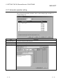
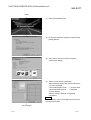
6.3.8 Device display format setting
Set the formats in which the devices read on the personal computer will be displayed.
Item
Bit device display
Description
Choose the bit device display format.
format
Monitor screen display Choose the combination of the character color and background color.
format
6 - 19
6 - 19
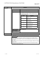
7 ABOUT THE PERSONAL COMPUTER
MELSOFT
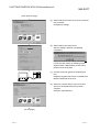
7. ABOUT THE PERSONAL COMPUTER
This chapter explains the setting items and display methods on the personal computer.
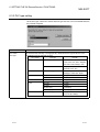
7.1 List of Personal Computer Setting Items
Making access to the address added to e-mail displays the following screen.
1)
2)
3)
4)
5)
6)
7
7)
8)
9)
10)
11)
12)
13)
14)
15)
16)
17)
7-1
7-1
7 ABOUT THE PERSONAL COMPUTER
No.
MELSOFT
Description
1)
Set the PLC series, PC side I/F, PLC side I/F and other station.
2)
Set the time when the line is disconnected from the personal computer.
3)
Shows the connection form between the server (personal computer) and PLC.
4)
Set the details of the port or board used by the server (personal computer).
5)
6)
7)
Set the details of the module used on the PLC side.
(The screen on the left is an example of a serial communication screen.)
Set within the range 1 to 9999.
Set within the range 0 to 5.
Set the head I/O No., station number and network No. of the module.
The setting items change depending on the module selected for the PLC side I/F.
8)
Specify the PLC No. to be accessed when a multi PLC system is configured.
9)
Choose the display format on the personal computer.
10)
Set the device to be read and its number of points.
11)
Choose the number of read points of the device to be diagnosed.
12)
Choose the program to be diagnosed.
13)
Choose the memory to be accessed.
14)
Choose the comment data to be diagnosed.
15)
Set the keyword for device comment search. (Within 32 characters)
16)
Execution makes access to the PLC.
17)
Choose when monitoring the tag.
7
7-2
7-2
7 ABOUT THE PERSONAL COMPUTER
MELSOFT
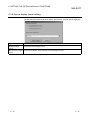
7.2 Providing Tag Display
This section explains the tag display screen.
1)
2)
3)
4)
Item
Description
1)
When TC is displayed, (Contact), (Coil), (Set value) or (Present value) is added to its display name.
2)
Select the tag you want to display from the tag list.
Monitors a list of devices chosen by tag selection.
3)
Note that the statuses of the devices read to the personal computer are those when start is clicked.
Note: The read devices do not vary in real time.
4)
7-3
Moves to the device monitor page.
7-3
7 ABOUT THE PERSONAL COMPUTER
MELSOFT
7.3 Monitoring the Devices
This section explains the device display formats.
The following gives the examples of the Web browser and personal computer displays
provided when the remote device monitor function is used.
(a) Word multi-point decimal
(b) Word multi-point hexadecimal
(c) Bit multi-point
7-4
7-4
7 ABOUT THE PERSONAL COMPUTER
MELSOFT
(d) Commented decimal
(e) Commented hexadecimal
(f) Commented binary
7-5
7-5
7 ABOUT THE PERSONAL COMPUTER
MELSOFT
7.4 Setting the Server (Personal Computer) Line Connection
This section explains the server (personal computer) side line disconnection timer
setting and line disconnection on the personal computer.
Item
Description
Server Side Circuit
Set the time until the line is disconnected.
Settings Time to
When making this setting, preset "Enable disconnection of dial up connection on client side" on the
disconnect the circuit
dialup setting screen.
Server side dialup
Disconnects the dialup connection.
disconnect execution
7-6
7-6
8 GETTING STARTED WITH GX RemoteService-I!
MELSOFT
8. GETTING STARTED WITH GX RemoteService-I!
This chapter describes the setting of GX RemoteService-I functions on the server
(personal computer) under the conditions presented in Section 8.1 and the
confirmation of tag displays and device displays on the personal computer.
Section 8.1 explains the setting of GX RemoteService-I.
Section 8.2 explains the varying of the monitor devices and the arrival of e-mail.
Section 8.3 explains the operation procedure of looking at the server (personal
computer) after the arrival of e-mail.
8.1 Setting GX RemoteService-I to the Server (Personal Computer)
Outline of setting example
(1) Setting of e-mail sending conditions
When the trigger condition is enabled, make settings to send e-mail to two
persons.
• When M1000 turns on, Mr. A is informed of a "robot" fault.
• When M1001 turns on, Mr. B is informed of a "press" fault.
(2) Setting of devices read by the personal computer
• Make tag settings (three tags) for confirming the system status.
• Make setting to read the annunciator (F) first for checking the fault status of the
system.
Conditions
Setting item
Operating mode
Setting
Automatic operation mode
Send mail (SMTP) server
8
Send mail (POP3) server
E-mail setting
Account name
Password
Refer to "Description for Use" or like sent from the provider and
make settings.
E-mail address
Dial up connection name
GX Remoteservice-I
PLC type
QCPU (Q mode), Qn (H)CPU
Transfer setup
PLC direct connection
F0
Device
Note: Set the F0 comment on GX Developer and write it to the PLC
CPU in advance.
Device range
setting
Points
16 points
Program
MAIN
Target memory
Program memory/device memory
Comment data
COMMENT
(Continued on next page)
8-1
8-1
8 GETTING STARTED WITH GX RemoteService-I!
MELSOFT
(From previous page)
Setting item
Tag setting
Setting
Tag name
Device name
Robot
M100
Robot controller fault
(Tag 1)
M101
Robot arm fault
M102
Servo amplifier fault
Press
X100
(Tag 2)
D100
Display format
Display name
Thermal fault
Decimal
Coolant pressure low
X130
Die fault
Transfer
M105
Rotary pump fault
(Tag 3)
X150
D110
Stocker cylinder fault
Decimal
Transfer motor
speed
Index
Plant A Line A
Trigger condition
M1000 turns on
Subject of message
1 Body of message
Fault occurred in robot.
A fault occurred in the line A robot.
Check the system.
SendTo e-mail
Mr. A aaa@***.co.jp
address
Auto run setting
Index
Plant A Line B
Trigger condition
M1001 turns on
Subject of message
Fault occurred in press
2 Body of message
A fault occurred in the line B press.
Check the system.
SendTo e-mail
Mr. B bbb@***.ne.jp
address
Dev. disp. setting
Character display (ON:
OFF:
)
Conceptual diagram of system
Robot fault
Internet
Press fault
8-2
Robot fault
Line A
Mr. A
Mr. B
When M1000 turns on,
e-mail is sent to Mr. A.
M1000
M1000
When M1001 turns on,
e-mail is sent to Mr. B.
M1001
M1001
Press fault
Line B
8-2
8
8 GETTING STARTED WITH GX RemoteService-I!
MELSOFT
(Start)
(1) Start GX RemoteService-I.
(2) Choose the automatic operation mode and click
[setting wizard].
(3) Set e-mail to notify the personal computer.
Click [E-mail setting].
(4) Set the e-mail common information.
Set the following data of the provider with whom
you have contracted.
• Send mail (STMP) server
• Account name
• Send mail (POP3) server
• Password
• E-mail address
After the setting is finished, click [Setting
completion].
Remark
For the settings, refer to "Description for Use" or like
sent from the provider.
(To next page)
8-3
8-3
8 GETTING STARTED WITH GX RemoteService-I!
MELSOFT
(From previous page)
(5) Set the dialup connection name to be connected
to the provider.
Click [Dial up setting].
(6) Set the dialup connection name.
After the setting is finished, click [Setting
completion].
Always make the dialup setting of Windows .
If it has not been made, the following screen
appears and the dialup setting screen of this
product cannot be opened.
R
(7) Connect the server (personal computer) and
PLC.
Prepare a program that can turn on M1000 and
M1001 beforehand for the PLC.
(8) Set the PLC series and PLC type of the PLC
CPU to be accessed first by the personal
computer.
Click [PLC type selection].
(To next page)
8-4
8-4
8 GETTING STARTED WITH GX RemoteService-I!
MELSOFT
(From previous page)
(9) Choose the PLC series and PLC type of the
PLC CPU to be connected to the server
(personal computer).
After the setting is finished, click [Setting
completion].
(10) Set the connection path from the server
(personal computer) to the PLC CPU.
Click [Transfer setup].
(11) Set the path for connection of the server
(personal computer) and PLC CPU.
After the setting is finished, click [Connection
test] to start a communication test.
When normal communication is made, the CPU
type appears in the CPU Type display field.
After the setting is finished, click [OK].
(12) Set the device, number of points, and program
name to be read first when the PLC CPU is
accessed by the personal computer.
Click [Device range setting].
(To next page)
8-5
8-5
8 GETTING STARTED WITH GX RemoteService-I!
MELSOFT
(From previous page)
(13) Set the device name (F0), number of points (16
points), and program name (MAIN).
Refer to Section 6.3.5 for detailed explanation of
the target memory and comment.
After the setting is finished, click [Setting
completion].
(14) Make setting to read different types of devices
(up to 10 types) together to the personal
computer.
Click [Tab setting].
(15) Choose No. 1 and click [Edit].
Out of the three tags to be set, Tag 1 will only
be explained here.
(16) Set the tag name, device names and display
names.
After the setting is finished, click [Setting
completion].
(Set Tag 2 and Tag 3 in the same procedure.)
(To next page)
8-6
8-6
8 GETTING STARTED WITH GX RemoteService-I!
MELSOFT
(From previous page)
(17) When editing Tag 2 or Tag 3, move the cursor
to No. 2 or 3 and click [Edit].
To end, click [Close].
(18) Make setting to monitor the system
automatically.
Click [Auto run setting].
(19) Choose No. 1 and click [Edit].
(20) Set the Watch, Index, Trigger condition
(M1000), Subject of message, Body of
message.
Click [SendTo settings].
(To next page)
8-7
8-7
8 GETTING STARTED WITH GX RemoteService-I!
MELSOFT
(From previous page)
(21) Set the SendTo e-mail address.
Setting Mr.A at watch 1.
After the setting is finished, click [Setting
completion].
(22) Click [Setting completion].
(23) Move the cursor to No. 2 and click [Edit].
(24) Set the Watch, Index, Trigger condition
(M1001), Subject of message, Body of
message.
Enable 2 under "Mail".
Click [SendTo settings].
(To next page)
8-8
8-8
8 GETTING STARTED WITH GX RemoteService-I!
MELSOFT
(From previous page)
(25) You can check the combinations for sending email on the left screen.
When the check is finished, click [Setting
completion].
(26) Set the display format of the screen to be
displayed on the personal computer.
Click [Dev. disp. setting].
(27) Choose "Character display (ON:
and click [Setting completion].
OFF:
)"
(To next page)
8-9
8-9
8 GETTING STARTED WITH GX RemoteService-I!
MELSOFT
(From previous page)
(28) Start the Web server software and click [Start].
Refer to Chapter 5 for starting the Web server
software.
(29) Click [Start auto run].
(End)
8 - 10
8 - 10
8 GETTING STARTED WITH GX RemoteService-I!
MELSOFT
8.2 Varying of Monitor Devices and Arrival of E-mail
Using the device test function of GX Developer, vary the monitor devices set on GX
RemoteService-I and make sure that e-mail arrives.
Preinstall GX Developer into the server (personal computer).
(Start)
(1) Start GX Developer installed in the server
(personal computer).
Read the PLC program from [Online] - [Read
from PLC].
For program reading operation, refer to the GX
Developer Operating Manual.
(2) After stating program monitoring from GX
Developer, choose [Online] - [Debug] - [Device
test] and set M1000 for "ON" and M1001 for
"ON" on the left screen.
When M1000 is turned "ON", e-mail is sent to
Mr. A.
When M1001 is turned "ON", e-mail is sent to
Mr. B.
For GX Developer operation, refer to the GX
Developer Operating Manual.
(3) E-mail is sent from GX RemoteService-I and
notifies the personal computers.
e-mail is sent to Mr. A
when M1000 turns on.
GX RemoteService-I
Mr. A
e-mail is sent to Mr. B
when M1001 turns on.
Mr. B
(End)
8 - 11
8 - 11
8 GETTING STARTED WITH GX RemoteService-I!
MELSOFT
8.3 Receiving E-mail and Looking at Devices on Personal Computer
This section explains how to perform operation to check the e-mail sent from GX
RemoteService-I and check the tag and device displays.
8.3.1 Until looking at tag
Outline of operation
The following operation example explains how to choose Tag 2 (press) and
check the operating status of the system after receipt of e-mail.
(Start)
(1) The e-mail sent from GX RemoteService-I is
received.
Check the received e-mail.
After confirming the message, click the URL of
"Tag reference".
(2) The left screen appears.
Choose [Tag select].
(To next page)
8 - 12
8 - 12
8 GETTING STARTED WITH GX RemoteService-I!
MELSOFT
(From previous page)
(3) As a list of tag names appears, choose "Press".
(4) Choose [Start].
(5) The devices set for the press are read.
(End)
8 - 13
8 - 13
8 GETTING STARTED WITH GX RemoteService-I!
MELSOFT
8.3.2 Until looking at devices
Outline of operation
Following the operation in Section 8.3.1, monitor the device (F) using "Device
reference" to check the details of the faulty status. The following operation
example explains how to change the monitored device to the data register (D).
(Start)
(1) The e-mail sent from GX RemoteService-I is
received.
Check the received e-mail.
After confirming the message, click the URL of
"Device reference".
(2) Scroll the screen down.
(3) Choose [Start].
(To next page)
8 - 14
8 - 14
8 GETTING STARTED WITH GX RemoteService-I!
MELSOFT
(From previous page)
(4) 16 points, starting from F0, in the MAIN program
where the device range has been set on the
server (personal computer) are read.
(5) After confirming the contents of F0, change the
device data to D100.
(6) Change F0 to D100.
(To next page)
8 - 15
8 - 15
8 GETTING STARTED WITH GX RemoteService-I!
MELSOFT
(From previous page)
(7) Choose [Start].
(8) The D100 value can be read.
(End)
8 - 16
8 - 16
9 TROUBLESHOOTING
MELSOFT
9. TROUBLESHOOTING
The following is the troubleshooting of the server (personal computer).
Phenomenon
Check
Corrective Action
Check that the dialup network has
Make sure that the dialup network exists in the
been installed.
Control Panel.
Check that "Dial up connection name"
Make sure that the connection target has been
of the dial up network has been set.
registered within the dialup network in the Control
Panel.
Connection cannot be made Check that the modem driver has been Make sure that the modem used for the modem
from the dialup network to
installed.
properties in the Control Panel is displayed.
the provider.
The modem does not dial.
Check by clicking the icon of the connection target
within the dialup network in the Control Panel.
The modem dials but connection
Check by clicking the icon of the connection target
cannot be made to the host.
within the dialup network in the Control Panel.
The line was connected but you cannot Check by clicking the icon of the connection target
log in.
within the dialup network in the Control Panel.
Dialup connection is
Connection is made from a place of
For dialup connection, enter ", (pause)" before the
instable.
weak radio wave with a mobile, or a
phone number.
(Connection cannot be
local line is used.
made sometimes.)
Check that the e-mail of GX
Make sure that correct values have been set to the
RemoteService-I has been set.
e-mail of GX RemoteService-I.
• Check that mail can be set to the
Check the settings for error.
specified destination from
Contact the provider for confirmation.
commercially available e-mail.
e-mail cannot be sent from
GX RemoteService-I.
• Check that the software can send
mail.
Check that the SMTP and POP3
server settings are correct.
• Check that the set character string is correct
(e.g. periods, colons).
• Check the SMTP and POP3 server settings
presented by the provider.
Check that the account name and
Confirm the account name and password
password have been set.
presented by the provider.
9
9-1
9-1
9 TROUBLESHOOTING
MELSOFT
The following is the troubleshooting of the personal computer.
Phenomenon
Check
Error appears in commented
monitor.
Error appears in T/C device
monitor.
Tag names cannot be
displayed.
Using GX Developer, check that device comments
have been written.
Check that the device comments are Display the device setting screen of the server
correct.
(personal computer) and check the registered device
comment names.
Check that the program name is
correct.
Display the device setting screen of the server
(personal computer) and check the registered
program name.
Check that tag setting has been made Display the tag setting screen of the server (personal
to the server (personal computer).
computer) and make sure that the tag names have
been registered and the setting is valid.
Check that disconnection from the
personal computer is enabled on the
server (personal computer).
The line cannot be
disconnected.
Common
to clients
Corrective Action
Check that device comments are
written to the PLC CPU.
Display the dialup setting screen of the server
(personal computer) and make sure that "Server Side
Circuit Settings Time to disconnect the circuit" has
been turned on.
Check that dialup disconnection timer
The dialup disconnection timer setting from the personal computer is
enabled on the server (personal
cannot be set.
computer).
Display the dialup setting screen of the server
(personal computer) and make sure that "Server Side
Circuit Settings Time to disconnect the circuit" has
been turned on.
When devices or comments are Check the script time-out period on
the server (personal computer).
displayed, a time-out occurs
frequently and they cannot be
displayed on the browser.
Change the script time-out period.
Refer to REMARKS for the changing method.
Communication cannot be
made with the PLC.
01802001
01802002
01802005
010*4030
010*4031
010*4032
(*: Any of 0 to F enters.)
An unusable device name or range is Check the device name and range in the PLC CPU
used.
manual.
REMARK
The following is the way to change the script time-out period.
(Start)
9
(1) Start Internet Information Service.
(To next page)
9-2
9-2
9 TROUBLESHOOTING
MELSOFT
(From previous page)
(2) Right-click the virtual directory "index" of GX
RemoteService-I.
(3) Click the "Configuration" button in the <Virtual
Directory> tab.
(4) Choose the <App Options> tab and change the
time-out period of the ASP script to about 200
seconds.
(End)
9-3
9-3
APPENDICES
MELSOFT
APPENDICES
APPENDIX 1 RESTRICTIONS
The following table indicates the restrictions on use of GX RemoteService-I.
Item
Monitor
Restrictions
The monitor display or like (inquiry to the personal computer) is slow or the monitor
display results in a time-out.
Setting check
Checks on set values, such as device names and ranges, are made by the server
(personal computer).
Line connection
The URL of the server (personal computer) must be mailed to the personal computer
every time the server (personal computer) dials up.
The IP address assigned by the provider that the server (personal computer) dials up
must be the global IP address.
The number of personal computers connectable to PWS simultaneously is up to 10.
If there are more than 10, HTTP error 403 is displayed on the browser.
When connection is made from the browser designed for the server (personal computer),
PWS counts the number of connected personal computers as 2.
A response from the server (personal computer) may be slow depending on the line
conditions and like of the provider and between the relayed Internet servers.
App
App - 1
App - 1
APPENDICES
MELSOFT
MEMO
App
App - 2
App - 2
INDEX
Ind
[A]
Automatic operation mode
About automatic operation ......................... 1- 3
Automatic operation setting .......................... 6-17
Setting GX RemoteService-I to server
(personal computer)....................................8- 1
Setting and procedure
Server (personal computer) ........................4- 2
Personal computer ......................................4- 4
[C]
Connection setup .......................................... 6-10
[T]
Tag setting......................................................6-15
[D]
Dialup setting.................................................. 6- 7
Displaying tags ............................................... 7- 3
Device/comment display examples ............... 7- 4
Device setting ................................................ 6-14
Device display format setting........................ 6-19
[E]
e-mail setting .................................................. 6- 5
[U]
Until looking at tags........................................8-12
Until looking at devices ..................................8-14
[W]
Web server installation
Windows 2000..........................................1- 1
Windows NT 4.0.......................................5- 4
Windows 98 ...............................................5- 7
R
R
R
[F]
Function list
Server (personal computer) ....................... 3- 1
Personal computer ..................................... 3- 2
[M]
Main screen .................................................... 6- 3
Manual operation mode
About manual operation ............................. 1- 4
[O]
Operating environment
Server (personal computer) ...................... 2-12
Personal computer .................................... 2-13
[P]
Personal computer
Line connection setting....................... 3- 2, 7- 6
PLC type setting ............................................. 6- 8
[S]
System device list
Connection from interface board................ 2- 6
Connection from serial port ........................ 2- 2
Types of usable modules ........................... 2- 8
Setting Wizard ............................................ 6- 2
Index - 1
Index - 1
MEMO
Ind
Index - 2
Index - 2
O
Operating Manual
Operating Manual
GX RemoteService-I Version 1 Operating Manual
MODEL
SW1D5-RAS-O-E
MODEL
CODE
13JU23
SH(NA)-080204-A(0112)MEE
HEAD OFFICE : 1-8-12, OFFICE TOWER Z 14F HARUMI CHUO-KU 104-6212,JAPAN
NAGOYA WORKS : 1-14 , YADA-MINAMI 5 , HIGASHI-KU, NAGOYA , JAPAN
When exported from Japan, this manual does not require application to the
Ministry of Economy, Trade and Industry for service transaction permission.
Specifications subject to change without notice.
SW1D5C-RAS-E