1
PARIS DESIGNER
REFERENCE MANUAL
© 1998 XLPrint Software Pty. Limited. All rights reserved.
This work is copyright. This manual and its accompanying software may not be reproduced by any means,
mechanical, electronic or otherwise, without the prior agreement and written consent of XLPrint Software Pty.
Limited or an appointed representative.
The Paris Designer Reference Manual
First Published, August 1998
Second Edition, May 1999
Revised, August, 1999
Third Edition, January, 2000
CD-ROM Edition, First Published, February, 2000
CD-ROM Second Edition, December 2000
Paris Designer is an XLPrint Software product.
The Paris Document System is a trademark of XLPrint Software Pty. Limited, Sydney, Australia
This document may contain or refer to information and products protected by copyright or patents and does not
convey any license under the patent rights of XLPrint Software Pty. Limited nor the rights of others. All product
names used in this manual are trademarks of their respective owners.
The information in this document is provided for reference only. Names and data used in examples are fictitious
and are provided for explanatory purposes only.
Written and produced by XLPrint Software Pty. Limited,
Suite 401, 220 Pacific Highway,
Crows Nest,
Sydney, NSW, 2065, Australia.
Printed in Australia
2
The Paris Designer Reference Manual
CONTENTS
AB OU T T H IS M AN U AL
20
S YMBOLS USED IN THIS MANUAL
20
PART 1: U S I N G T H E F U N C T I O N S I N T H E
ENVIRONMENT EDITOR
C H AP T E R 1 :
FUNCTIONS IN THE ENVIRONMENT
EDITOR FILE MENU
22
23
O PENING AN E NVIRONMENT
25
S AVING AN E NVIRONMENT
26
S AVING AN E NVIRONMENT U NDER A N EW N AME
27
R ECORDING E NVIRONMENT I NFORMATION
28
Recording design information
29
Modifying a Paris Job Ticket
30
Modifying a job ticket for an environment
31
L OADING A S AMPLE OF THE P RINTSTREAM D ATA
The Paris Designer Reference Manual
32
3
Contents
C APTURING A S AMPLE OF THE P RINTSTREAM D ATA
34
How do I capture a data file from the Serial port?
35
How do I capture data from a Novell print queue?
39
How do I capture data from an LPD Queue?
43
C REATING /E DITING M ODEL P RINTSTREAM D ATA
45
Creating a model of the printstream data
45
Editing a sample of the actual printstream
45
File size in the Edit Data function
45
Using the keyboard in the Edit Data File function
46
Creating a model printstream data file
47
Editing the currently loaded model/sample data file
49
Loading a model/sample data file into the Edit Data File
dialogue
52
P RINTING A P ROOF OF THE C URRENT P AGE
53
S ELECTING A P RINT D ESTINATION
54
ADDING , M ODIFYING AND R EMOVING A P RINT D ESTINATION 55
Adding a printer
56
Managing Printer Resources
69
Using Barcodes in Paris
81
Physical Page Shift
87
Saving the printer definition
88
Modifying/Removing a printer
89
R ESET R ESOURCES FUNCTION
92
4
The Paris Designer Reference Manual
Contents
C H AP T E R 2 :
FUNCTIONS IN THE ENVIRONMENT
EDITOR SYSTEM MENU
D EFINING THE S YSTEM S ETTINGS
93
94
The Grid
95
Edit Options
96
Autosave and Save Options
97
V IEWING THE DOCUMENT
98
S WITCHING E DITORS
99
P REVIEWING A DOCUMENT BEFORE PRINTING
C H AP T E R 3 :
FUNCTIONS IN THE ENVIRONMENT
EDITOR VIEW AND TOOLS M ENUS
100
101
V IEW M ENU
101
T OOLS M ENU
102
C H AP T E R 4 :
FUNCTIONS IN THE TEXT EDITING
MENU
T EXT E DITING O PTIONS
The Paris Designer Reference Manual
103
104
5
Contents
C H AP T E R 5 :
FUNCTIONS IN THE ENVIRONMENT
MENU
T HE I NPUT F ILTER F UNCTION
107
109
Why is an Input Filter needed?
109
Do I need to modify the Input Filter for my print files?
120
When would I not use the standard Input Filter values?
121
Using the Input Filter to set the character functions
122
How do Input Character settings interact with PCC byte
instructions (Spacing Settings)?
128
T HE T RANSLATION T ABLE FUNCTION
129
What is the purpose of a Translation Table and why is it needed?130
What are the translation tables supplied with the Paris Designer?132
What is the scope of the Translation Table?
134
At what stage of processing is the Translation Table
applied?
135
What relevance does the Translation Table have to
Control Bytes?
136
How is the Translate Control Bytes option turned
on and off?
137
Using the Translation Table
139
T HE I NPUT S ETTINGS FUNCTION
6
143
What is the function of Input Settings?
143
Using the Input Settings ‘Skip at start of Report’
function
144
The Input Settings ‘Input Processor Plug In’ function
145
Using Input Settings
146
The Paris Designer Reference Manual
Contents
T HE S PACING S ETTINGS FUNCTION
147
What is the function of Spacing Settings?
147
What are PCC bytes?
148
How do I know if the printstream contains PCC bytes?
149
How do I avoid printing the PCC byte?
149
Which spacing method takes priority?
150
Using the Spacing Settings function
151
Adding a PCC character
162
T HE O UTPUT S ETTINGS FUNCTION
163
How does Font Indexing work?
165
How does Color Indexing work?
168
How do I use the Copies options
169
What is the effect of the Copy Sensitive Processing
Required option?
170
How do the Collate/Copy-Sensitive options affect
processing?
171
What are the differences between the Engine or the
Output Device handling Copy Processing?
173
Using Output Settings
174
T HE P RINT O RDER FUNCTION
182
T HE C URRENT P AGE D EFINITION FUNCTION
183
Using the View/Change Page Definition function
T HE F IELDS FUNCTION
184
187
Field Value
187
Fields and Events
187
The Paris Designer Reference Manual
7
Contents
The order of Field actions
187
Defining Fields
188
Adding and editing a Field
189
Field Calculations
201
T HE I NDEXING FUNCTION
220
T HE O PERATOR M ESSAGES FUNCTION
221
Using the Reply feature
222
Using the Operator Messages function
223
T HE CEP FUNCTION
224
T HE V IEW P AGE ATTRIBUTES FUNCTION
225
T HE S ELECT T EXT B LOCK FUNCTION
227
C H AP T E R 6 :
FUNCTIONS IN THE ENVIRONMENT
EDITOR MOVE MENU
228
U SING THE M OVE FUNCTIONS
228
C H AP T E R 7 :
229
FUNCTIONS IN THE EVENTS MENU
U SING T ESTS
8
230
About events and tests
230
How tests work
231
Setting the test conditions
239
The Paris Designer Reference Manual
Contents
Setting up two tests
242
P AGE /P ARA E VENTS
243
Types of Page/Para events
244
Adding and editing a Page/Para event
245
T HE P AGE /P ARA C HANGE F ORM E VENT FUNCTION
247
When would I use a Page/Para Change Form event?
247
Adding a Page/Para Change Form event
248
T HE P AGE /P ARA C HANGE B ACK F ORM E VENT FUNCTION
249
When would I use a Change Back Form event?
249
Adding a Change Back Form event
250
T HE P AGE /P ARA C HANGE P AGE D EFINITION E VENT
251
FUNCTION
When would I use a Change Page Definition event?
251
Adding Change Page Definition event
252
T HE P AGE /P ARA C HANGE O UTPUT E VENT L IST E VENT
254
FUNCTION
Adding a Change Output Event List event
T HE P AGE /P ARA E ND C URRENT P AGE E VENT FUNCTION
255
256
How would I use an End Current Page event?
257
Adding an End Current Page event
258
T HE P AGE /P ARA E ND T EXT B LOCK E VENT FUNCTION
Adding an End Text Block event
The Paris Designer Reference Manual
260
262
9
Contents
T HE P AGE /P ARA S ELECT I NPUT T RAY E VENT FUNCTION
Adding a Select Input Tray event
264
264
T HE P AGE /P ARA S ELECT O UTPUT T RAY E VENT FUNCTION 265
Adding a Select Output Tray event
T HE P AGE /P ARA U PDATE F IELD E VENT FUNCTION
Adding a Page/Para Update Field event
265
266
267
T HE P AGE /P ARA S ELECT D EVICE F EATURES E VENT
FUNCTION
268
T HE P AGE /P ARA P AGE S UPPRESS E VENT FUNCTION
269
Adding a Page Suppress event
R UNTIME E VENTS
270
271
What is a Runtime event?
272
CEP DJDE compatibility
273
How do Runtime events differ from other input events?
274
Why are Runtime events used?
275
How are embedded Runtime events activated?
277
Using the Runtime Event Modifications option
280
E NVIRONMENT C HANGE E VENTS
285
Packing the Environment Change event list
286
Adding an Environment Change Event
287
Editing an Environment Change Event
288
10
The Paris Designer Reference Manual
Contents
C H AP T E R 8 :
FUNCTIONS IN THE UTILITIES
MENU
T HE R ESOURCE M ANAGER
289
290
How does Resource Packing work?
291
Packing Resources
292
Setting the Packer Options
293
Packing Files
295
Unpacking Resources
298
Resource Manager: FAQs and Troubleshooting
300
F ONT R EFERENCE U TILITY
Using the Font Reference Utility
E URO R ATES U TILITY
303
304
306
Euro Rates, Fields and Events
306
Access levels in the Euro Rates utility
308
E URO F UNCTIONS IN THE P ARIS D ESIGNER
318
U SING THE E URO R ATES U TILITY AND E URO
325
FUNCTIONS
Adding a currency value to the Euro Rates table
326
Adding fields to the field list for use in currency
conversion
328
ISO 4217 Currency Codes
341
C H AP T E R 9 :
FUNCTIONS IN THE HELP MENU
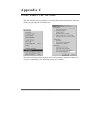
Tip of the Day
350
351
The Paris Designer Reference Manual
11
Contents
Multiple Licensing
351
Paris Designer Help
352
PART 2: U S I N G T H E F U N C T I O N S I N T H E
FORM EDITOR
C H AP T E R 1 0 :
FUNCTIONS IN THE FORM EDITOR
FILE MENU
354
355
C REATING A NEW ( BLANK ) FORM
357
L OADING A FORM
358
S AVING A FORM
359
S AVING A FORM UNDER A NEW NAME
360
C HANGING FORM PAGE ATTRIBUTES
361
C REATING A SUMMARY OF THE FORM FILE
362
Summarizing the form file
363
M ERGING FORM S TO CREATE A NEW FORM
364
O V E R L AYIN G A F OR M T O AC T AS A T E M P L AT E
365
Removing an overlaid form
12
The Paris Designer Reference Manual
366
Contents
P RINTING A PROOF OF THE CURRENT FORM
367
S ELECTING A PRINT DESTINATION
368
M ODIFYING A P RINT D ESTINATION
369
R ESETTING R ESOURCES
370
C H AP T E R 1 1 :
FUNCTIONS IN THE FORM EDITOR
SYSTEM MENU
D EFINING THE S YSTEM S ETTINGS
371
372
The Grid
373
Edit Options
374
Autosave and Save
375
V IEWING THE DOCUMENT
376
S WITCHING E DITORS
377
P REVIEWING A DOCUMENT BEFORE PRINTING
378
C H AP T E R 1 2 :
FUNCTIONS IN THE FORM EDITOR
VIEW MENU
The Paris Designer Reference Manual
379
13
Contents
C H AP T E R 1 3 :
FUNCTIONS IN THE FORM EDITOR
TOOLS MENU
P ARIS F ORM E DITOR H ELP M ENU
380
381
PART 3: E D I T I N G T H E S E T T I N G S F O R D Y N AM I C
AN D S T AT I C F O R M E L E M E N T S
383
C H AP T E R 1 4 :
EDITING TEXT SETTINGS
384
Default Text Settings dialogue
384
View/Change Text Settings dialogue
385
Setting Text Attributes
386
Setting the Position for Added Text
388
Setting the Properties for a Dynamic Text Element
390
Setting Text Alignment, Word Wrapping and Color attributes
from the Tools Bar
391
Pasting text into the Environment or Form Editor
C H AP T E R 1 5 :
EDITING LINE SETTINGS
392
393
Default Line Settings dialogue
393
View/Change Line dialogue
394
Setting Line Attributes
395
Setting the Line Position
396
Setting the Properties for a Dynamic Line Element
397
Setting Line weight, style and color attributes from the
Tools Bar
397
14
The Paris Designer Reference Manual
Contents
C H AP T E R 1 6 :
EDITING CIRCLE SETTINGS
398
Default Circle Settings dialogue
398
View/Change Circle dialogue
399
Setting Circle Attributes
400
Setting the Circle Position
401
Setting the Properties for a Dynamic Circle Element
402
Setting Circle line and fill color attributes from the
Tools Bar
402
C H AP T E R 1 7 :
EDITING BOX SETTINGS
403
Default Box Settings dialogue
403
View/Change Box dialogue
404
Setting Box Attributes
405
Setting Box Corners
406
Setting the Position for a Box
407
Setting the Properties for a Dynamic Box Element
408
Setting the Box line and fill color attributes from the
Tools Bar
408
C H AP T E R 1 8 :
EDITING GRAPHIC SETTINGS
409
Default Graphic Settings dialogue
409
View/Change Graphic dialogue
410
Previewing a Graphic before adding
411
Setting Graphic Attributes
412
Setting the Properties of a Dynamic Graphic Element
413
Setting the Frame for the Graphic
414
Re-Scaling a Graphic
415
The Paris Designer Reference Manual
15
Contents
C H AP T E R 1 9 : E D I T I N G C H A R T S E T T I N G S
417
Default Chart Settings dialogue
417
View/Change Chart Settings
418
Chart Types
419
Simple Plot Chart
420
Complex Plot Chart
424
Simple Bar Chart
434
Complex Bar Chart
439
Pie Chart
453
C H AP T E R 2 0 : E D I T I N G T E X T B L O C K S E T T I N G S
462
T EXT B LOCK S ETTINGS
464
Setting the Text Block Attributes
465
Setting the Text Block Position
467
Setting Text Block Options
469
Adding Local Text Block events
472
How are Data Change events used?
473
How are Update Field Events used?
495
How are Change Form events used?
501
How are Change Back Form events used?
504
How are Select Device Features events used?
507
Editing, deleting and copying Local Text Block events
509
C H AP T E R 2 1 : U S I N G T H E F O N T L I S T F U N C T I O N
511
C REATING A F ONT L IST
512
Adding Fonts to the Font List
16
The Paris Designer Reference Manual
513
Contents
L OADING , E DITING AND S AVING THE F ONT L IST
514
Loading the Font List
515
Saving the Font List
515
Editing the Font List
516
PART 4 : C O M M O N F U N C T I O N S I N T H E
P AR I S D E S I G N E R
C H AP T E R 2 2 : T H E C O L O R P A L E T T E F U N C T I O N
518
519
Load Palette
520
Save Palette
521
Custom Palette
521
What Color Palettes are available?
522
How is a color applied to an element?
525
How is a Color mixed?
525
How is the Color Palette saved?
525
U SING THE C OLOR P ALETTES
526
Adding a color to an element using the default
color palette
526
Adding the color to an element using a Paris system
Palette
527
Mixing a Custom color
530
Creating a Custom Palette
533
Saving the color palette
534
Loading a Color Palette (.PAL file)
535
The Paris Designer Reference Manual
17
Contents
C H AP T E R 2 3 :
THE INTERNAL CLIPBOARD
FUNCTION
U SING THE C LIPBOARD
536
537
Copying fonts onto the Clipboard
538
Copying fonts from the Clipboard
540
Copying Local Text Block Events onto the Clipboard
543
Copying Local Text Block Events from the Clipboard
545
Copying Fields to and from the Clipboard
547
Copying a page definition to and from the Clipboard
553
A P P E N D I X A:
USING THE M EDIA M APPING
FUNCTION
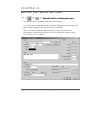
S ETTING UP M EDIA M APPING
562
563
Adding ‘*XLPInputMedia’ statements
563
Using Media Mapping in an Environment
564
Matching the mappings to the printer
571
Paris StockSet Support
572
AP P E N D IX B: CR E AT IN G AN D PR E P AR IN G NOV E L L PR IN T
QUEUES FOR INPUT INTO PARIS
578
How do I create a new Novell queue for input?
579
How do I prepare a Novell queue for input?
581
AP P E N D IX C:
USING XEROX CEP OPTIONS
588
General Options
589
Spacing Options
591
DJDE Options
592
18
The Paris Designer Reference Manual
Contents
AP P E N D IX D:
DEVICE SPECIFIC FEATURES IN THE
PARIS SYSTEM
594
U SING D EVICE S PECIFIC F EATURES
595
Inserting Code
595
Implementation of the Device Specific feature
595
Example of an XPD file using Device Specific features
601
INDEX
609
The Paris Designer Reference Manual
19
AB O U T T H I S M AN U AL
This manual describes the use of the PARIS Designer system and is to be used in
conjunction with the Paris Designer User’s Manual and the Paris Spooler
Technical Manual.
????
While every effort is made to keep the information in this manual up-todate, you may find that the PARIS Help available in your PARIS system
provides the most current information.
PARIS Help contains all the information available in the PARIS
manuals, is fully indexed and is constantly updated and improved.
????
SYMBOLS
U S E D I N TH I S M AN U AL
Symbols will appear regularly in the text or in the column adjacent to the text to
mark special information that supplements the textual theme or topic.
The symbols may flag additional information such as suggestions, advice or
warnings or may be an illustration of the topic of the text. The symbols used in this
manual are as follows:
NOTE:
This symbol indicates information supplementary to the current text.
TIP: This symbol indicates a practical hint.
WARNING!
This symbol is to draw your attention to a significant item or topic.
20
The Paris Designer Reference Manual
P ART O NE
U SING THE F UNCTIONS
E NVIRONMENT E DITOR
IN THE
I N THIS P ART :
CHAPTER 1: FUNCTIONS IN THE ENVIRONMENT EDITOR FILE MENU
CHAPTER 2: FUNCTIONS IN THE ENVIRONMENT EDITOR SYSTEM MENU
CHAPTER 3: FUNCTIONS IN THE ENVIRONMENT EDITOR VIEW AND
TOOLS MENUS
CHAPTER 4: FUNCTIONS IN THE ENVIRONMENT EDITOR TEXT EDITING
MENU
CHAPTER 5: FUNCTIONS IN THE ENVIRONMENT MENU
CHAPTER 6: FUNCTIONS IN THE ENVIRONMENT EDITOR MOVE MENU
CHAPTER 7: FUNCTIONS IN THE EVENTS MENU
CHAPTER 8: FUNCTIONS IN THE UTILITIES MENU
CHAPTER 9: FUNCTIONS IN THE HELP MENU
PART ONE
USING THE FUNCTIONS IN THE ENVIRONMENT
EDITOR
The Environment Editor is introduced to you in Chapter 2 of the Paris Designer
User’s Manual where the editor window and the Tools Bar are described.
Part One of this manual takes you through each of the functions in the
Environment Editor’s menus. The use of each function is explained and illustrated,
as are any associated dialogues.
22
The Paris Designer Reference Manual
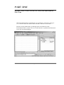
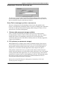
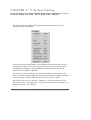
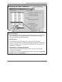
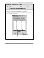
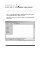
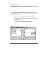
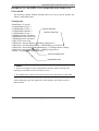
CHAPTER 1:
File
FUNCTIONS IN THE ENVIRONMENT EDITOR
FILE MENU
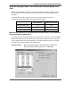
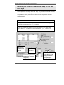
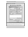
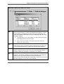
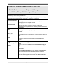
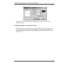
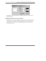
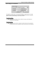
The File Menu lists the functions relevant to loading and saving environment files,
opening, capturing and editing data files, printing, selecting and modifying printers
and resetting resources
Below the Exit option, up to four of the most recently used environments will be
displayed.
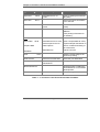
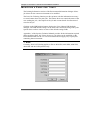
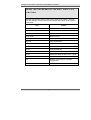
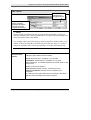
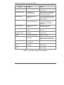
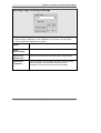
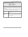
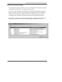
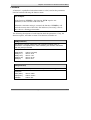
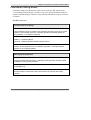
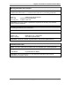
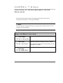
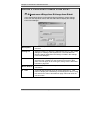
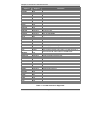
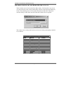
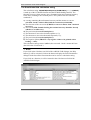
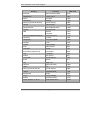
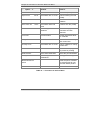
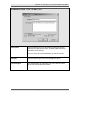
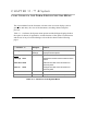
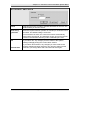
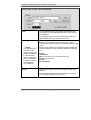
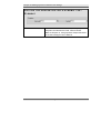
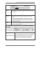
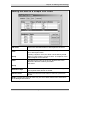
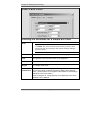
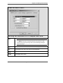
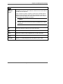
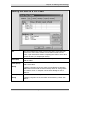
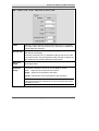
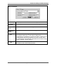
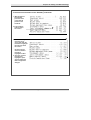
Table 1 - 1 shows the File menu options, the dialogue displayed when the option is
chosen (if applicable), and the function of the option.
Each function and the use of any associated dialogue are described in detail on the
following pages.
The Paris Designer Reference Manual
23
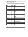
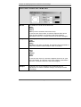
Chapter 1: Functions in the Environment Editor File Menu
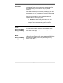
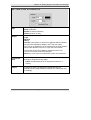
Function
Dialogue
Open Env
Alt+O
Save Env
Alt+S
Select/Enter File To
Load
Used to:
Open an existing environment
file (.ENV)
Save environment information
to an .ENV file.
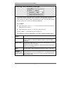
Save Env As Alt+A
Select/Enter Save File
name
Create an environment file
(.ENV).
Env Info
File Information
Record information about the
.ENV file.
Enter printing information for
job ticketing.
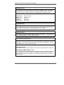
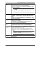
Data:
Open Data
Alt+D
Capture Data
Edit Data
Print
Select/Enter File to Load
Open a sample data file .DTA).
Select Input Source for
Data Capture
Capture sample data stream to
use for creation and testing of
an environment
Edit Data File
Edit the .DTA file
Alt+P
Send the current page to the
printer for proofing
Select Printer
Select Print Destination
Select the print destination
Modify Printers
View/Change Print
Destinations
Modify printer settings.
Reset Resources
Reset the printer, initialize the
download list for non-hard disk
based printers.
Exit
Exit the Designer.
Table 1 - 1: Functions in the Environment Editor File Menu
24
The Paris Designer Reference Manual
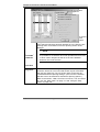
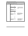
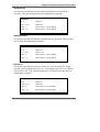
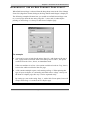
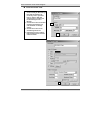
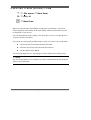
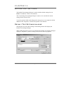
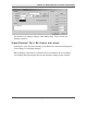
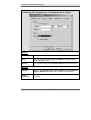
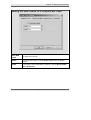
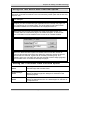
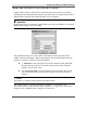
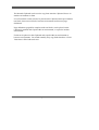
OPENING AN ENVIRONMENT
File menu
Open Env
Alt + O
Select/Enter File To Load dialogue
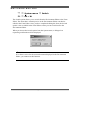
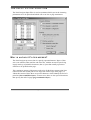
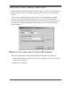
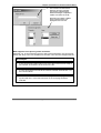
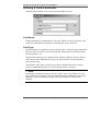
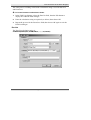
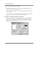
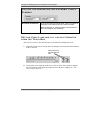
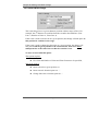
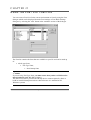
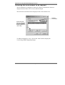
Selecting the Open Env option from the File menu (or using the shortcut keys
Alt+O), will display the Select/Enter File to Load (.ENV) dialogue for loading an
environment file into the Environment Editor.
NOTE: The Select/Enter File To Load dialogue is displayed when any files are
to be loaded in the Designer. The extension in the File field indicates the file type.
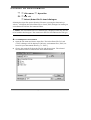
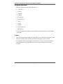
To load/open an environment:
1. Open the File menu and choose Open Env. The Select Enter File To Load
(*.ENV) dialogue will be displayed. [In Paris, environment files (.ENV) are
stored in a pre-determined directory, i.e. \ENV.]
2. Choose the required file from the File list and choose Open. The selected
environment will be loaded into the Environment Editor.
The Paris Designer Reference Manual
25
S AV I N G A N E N V I R O N M E N T
File menu
Save Env
Alt + S
Save Button
If you have made changes to the current environment, you can save the changes by
selecting Save Env from the File menu, using the shortcut keys Alt+S or clicking
on the Save button in the Files Bar.
Save Button
If no changes have been made to the environment, the option will not be available
in the menu and the Save button will be inactive in the Files Bar.
If you want to save an environment under another name, or create a new
environment, the Save Env As option is used (refer to the following section).
NOTE:
If you try to exit the Designer without saving an environment you have changed, a
message dialogue will appear. You can choose to save or discard any changes you
have made.
26
The Paris Designer Reference Manual
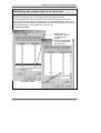
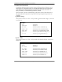
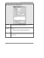
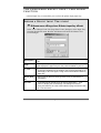
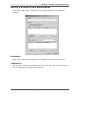
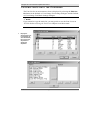
S AV I N G A N E N V I R O N M E N T U N D E R A N E W
NAME
File menu
Save Env As
Alt + A
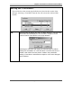
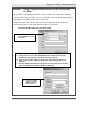
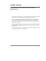
Select/Enter Save File Name dialogue
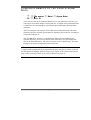
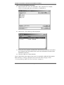
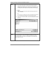
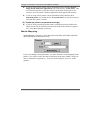
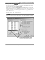
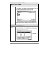
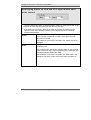
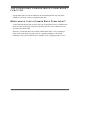
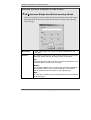
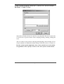
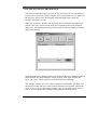
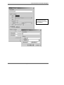
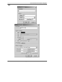
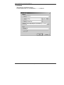
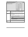
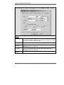
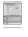
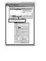
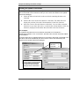
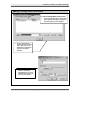
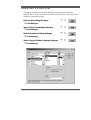
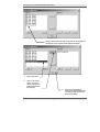
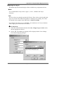
Selecting the Save Env As option (or using the shortcut keys Alt+A), displays the
Select/Enter Save File Name (.ENV) dialogue to save an environment under
another name or create a new environment.
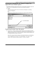
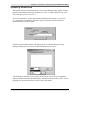
To save an environment under a new name:
1. Open the File menu and choose Save Env As from the menu (or press Alt+A).
The Select/Enter Save File Name dialogue will be displayed.
2. Type the new filename in the ‘File’ field and choose Save. If the environment
name already exists, you will be prompted with an ‘Overwrite Yes/No’
message, otherwise the environment will be saved under the new filename.
2. Type the new
filename, then
The Paris Designer Reference Manual
27
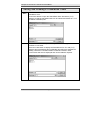
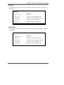
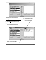
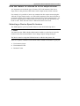
R E C O R D I N G E N V I R O N M E N T I N F O R M AT I O N
File menu
dialogue
Env Info
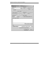
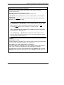
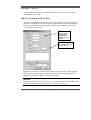
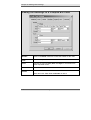
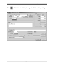
Environment Information
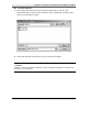
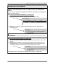
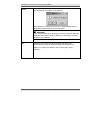
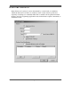
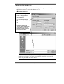
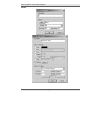
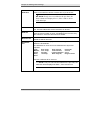
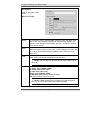
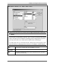
Selecting the Env Info option from the File menu displays the Environment
Information dialogue. Design and printing information on the current environment
file can be recorded in the dialogue.
Whenever the environment is opened, the dialogue can be displayed to confirm
and update the information. The date and time are automatically updated by the
system to reflect the last save.
28
The Paris Designer Reference Manual
Chapter 1: Functions in the Environment Editor File Menu
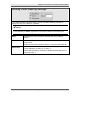
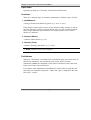
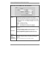
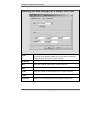
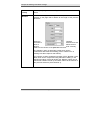
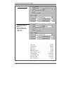
RECORDING
D E S I G N I N F O R M ATI O N
D E S I GN I N FOR M AT I ON
Selecting the Env Info option from the File menu displays the Environment
Information dialogue.
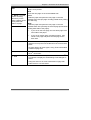
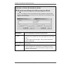
To enter the Design Information for the current environment, proceed as follows:
Designer
Description
Enter the name of the designer of the environment.
Enter a description of the environment file (for example,
monthly invoice, quarterly statement, monthly bonus points).
Up to 255 characters (or 5 lines of text) can be entered
Last Changed
29
This field displays an automatic log of the date and time when
the environment file was last saved.
The Paris Designer Reference Manual
Chapter 1: Functions in the Environment Editor File Menu
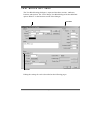
MODIFYING
A
P AR I S J O B T I C K E T
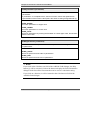
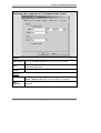
The Printing Information section of the Environment Information dialogue allows
job tickets for the current environment to be modified.
The Paris Job Ticketing function provides printers with the information necessary
to create banner sheets for print jobs. The banner sheet can contain the name of the
user sending the job, a description of the job and account details for allocation of
costs for the job.
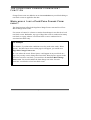
Clicking on the LPR Defaults button displays the View/Change LPR Defaults
dialogue. The LPR default settings can be used if the control file being read by the
Spooler does not have entries in some of the default settings fields.
Appendix C of the Spooler Technical Manual provides all the information required
about modifying Paris Job Tickets, however a job ticket can be modified via the
Environment Editor for the current environment and will apply only to print jobs
containing that environment.
NOTE:
Currently, Paris Job Ticketing applies to Xerox 4050 NPS, 4850 NPS, 4090 NPS,
4890 NPS and 4635 NPS printers only.
30
The Paris Designer Reference Manual
Chapter 1: Functions in the Environment Editor File Menu
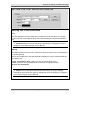
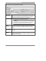
MODIFYING
A J O B TI C K E T F O R AN E N V I R O N M E N T
PRINTING INFORMATION
Selecting the Env Info option from the File menu displays the Environment
Information dialogue. This will contain the Design Information for the environment.
To modify a job ticket for the environment, enter the Printing Information as follows:
User Name
A name associated with the print job, usually the sender.
Title
A name associated with the job, usually the name of the type of
document.
Accounting
The name of the account that will be charged for the printing
costs associated with the job.
The accounting details will appear in the comma delimited file on
NPS and are available from there if required.
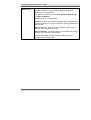
LPR Defaults
Clicking on the LPR Defaults button will display the View/Change
LPR Defaults dialogue.
The dialogue displays settings for the Host, User, Class, Job and
Input names and the Title of the job.
If the control file being read by the Spooler does not have an
entry in some of these fields, these settings are used to insert a
default name.
For example, a job name that may not be in the control file may
be inserted by the user as a default name.
The default job name may be passed on through the Spooler’s
LPR control file as if it was in the control file being read by the
Spooler.
31
The Paris Designer Reference Manual
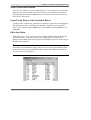
LOADING A SAMPLE OF THE PRINTSTREAM
D ATA
File menu
Data
Open Data
Alt + D
To be able to create an environment that processes your print files correctly, you
will require an accurate sample of each print file. A sample of the printstream data
is loaded into an environment by selecting the Open Data option from the Data
sub-menu.
The Paris Designer will list up to four of the last used data files below the Data
sub-menu, the most recently opened data file appearing first in the list. Clicking on
a listed file will open it.
The ‘\PARIS\DTA’ directory is a default only. Data can be loaded from any
available directory, however it would be more efficient to store all sample data
files in the default directory. The .DTA extension is also a default only. The Paris
Designer can accept any legitimate DOS extensions.
NOTE
A sample of the printstream can be captured from your data files or can be created in
the Edit Data File dialogue. Refer to Capturing a Sample of the Printstream Data on
page 34 and Creating a model of the printstream data on page 45.
18
The Paris Designer Reference Manual
Chapter 1: Functions in the Environment Editor File Menu
To load a data file:
1. Choose the Open Data option (or using the shortcut keys Alt+D). The
Select/Enter File to Open (.DTA) dialogue will be displayed, listing the data
files in your Designer system.
2. Select the required file from the File List, then choose Open.
NOTE:
Loading a sample printstream data file is also explained in Chapter 3 of the Paris
Designer User’s Manual.
33
The Paris Designer Reference Manual
CAPTURING A SAMPLE OF THE PRINTSTREAM
D ATA
File menu
Data
Capture Data
Designing a Paris environment that processes your print files correctly requires an
accurate sample of the corresponding input data (print file).
It is possible to create sample data files via the Data/Edit Data function, however
you must ensure that the data file is identical to any live data that will be used by
the Paris Spooler. Alternatively, the Paris Designer’s ‘Capture Data’ function can
be used.
In order to capture an accurate sample of data from your print files, Paris includes
a ‘Capture Data’ function that allows you to direct sample data files to disk for
future use in the Environment Editor. In this way you can be sure that your
environment is configured for ‘live’ data.
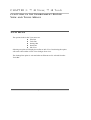
The Capture Data function allows you to capture data to disk from either:
the PC’s Serial port,
LPD,
a Novell print queue.
NOTE:
Novell print queues will only be displayed if you have the Novell client 32 bit
netware on your PC.
18
The Paris Designer Reference Manual
Chapter 1: Functions in the Environment Editor File Menu
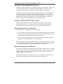
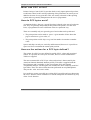
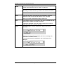
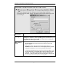
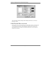
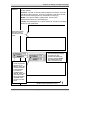
HOW DO I
PORT?
C AP TU R E A D ATA F I L E F R O M TH E
S E R I AL
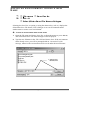
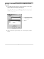
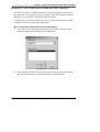
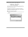
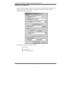
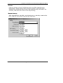
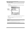
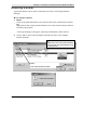
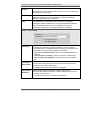
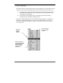
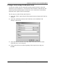
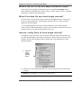
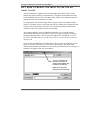
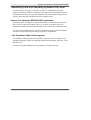
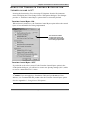
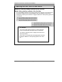
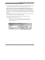
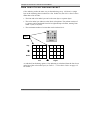
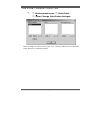
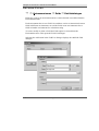
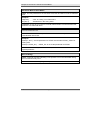
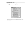
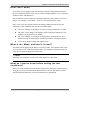
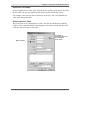
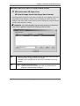
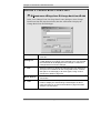
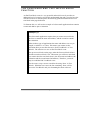
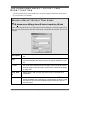
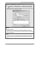
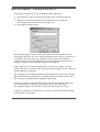
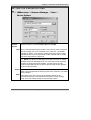
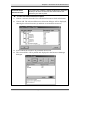
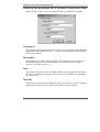
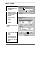
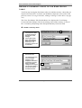
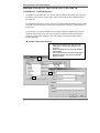
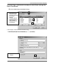
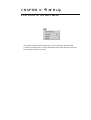
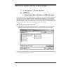
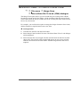
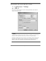
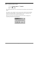
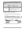
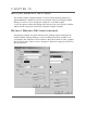
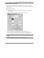
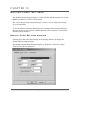
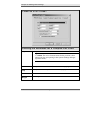
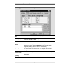
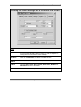
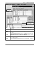
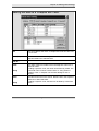
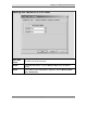
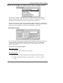
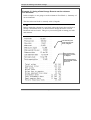
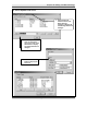
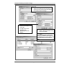
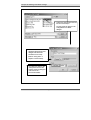
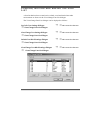
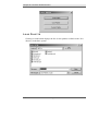
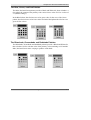
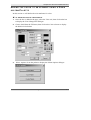
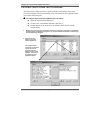
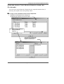
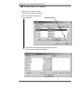
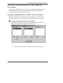
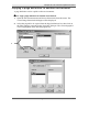
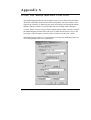
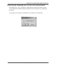
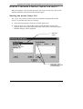
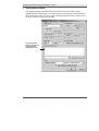
1. Choose the Capture Data option from the Data sub-menu. The Select Input
Source for Data Capture dialogue will be displayed.
In the Input Type section of the dialogue, the ‘Type’ drop-down menu will
display a list of available options, including ‘Serial Port’, and any available
Novell or LPD print queue.
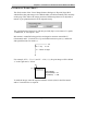
2. Select Serial Port from the
drop-down menu to display a
list of serial ports.
2. Select the ‘Serial Port’ option to display a list of four serial ports, COM1 to
COM4.
35
The Paris Designer Reference Manual
Chapter 1: Functions in the Environment Editor File Menu
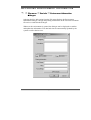
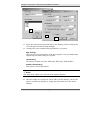
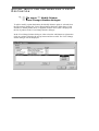
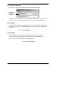
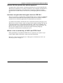
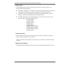
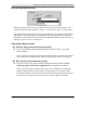
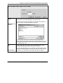
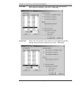
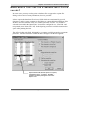
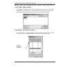
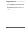
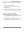
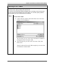
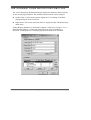
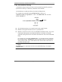
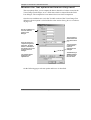
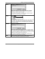
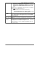
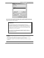
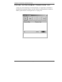
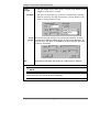
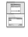
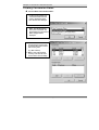
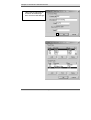
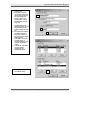
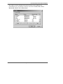
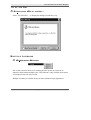
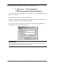
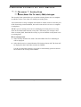
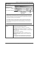
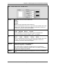
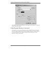
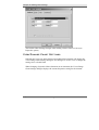
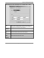
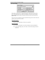
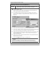
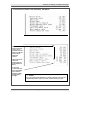
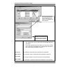
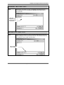
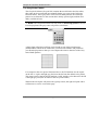
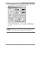
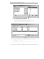
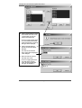
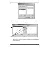
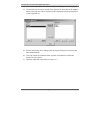
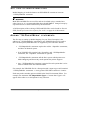
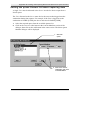
3
4
5
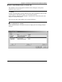
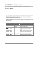
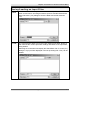
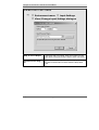
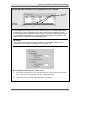
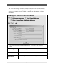
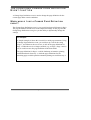
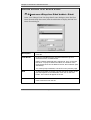
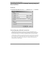
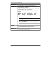
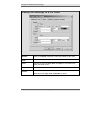
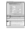
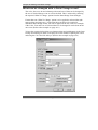
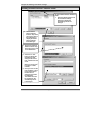
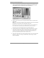
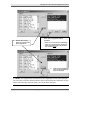
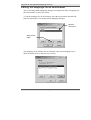
3. Select the required serial port and click on the ‘Settings’ button to display the
View/Change Serial Port Settings dialogue.
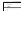
4. Configure the serial communications parameters, as required:
Byte Settings
These must be set to match those of the host computer. Ask your maintenance
engineering staff what settings are required.
Handshaking
The options available are None; DTR Only; RTS Only; DTR and RTS.
Software Handshaking
This option is selected by default.
NOTE:
The ‘Page Eject’ option is not relevant in the Capture function.
5. Once the settings are configured, choose OK to exit the dialogue, choose OK
again to exit the next dialogue to display the Select/Enter Save File Name
dialogue.
36
The Paris Designer Reference Manual
Chapter 1: Functions in the Environment Editor File Menu
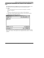
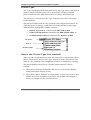
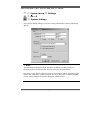
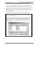
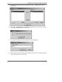
Defining the destination file name for the captured
data
The default path displays \PARIS\DTA as the directory location in which to store
the sample file. It is recommended to always use the default destination.
6. Either:
Select a file from the File List to overwrite an existing file, (a warning
message will appear),
Or:
Type the new file name in the ‘File’ box (with a .DTA extension).
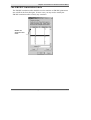
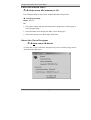
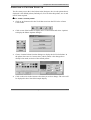
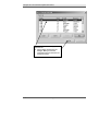
7. Choose OK. The File Capture/Transfer dialogue will be displayed and the
capture process will begin immediately.
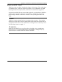
The destination directory and filename will be displayed in the ‘Name’ box in the
dialogue. The ‘Status’ of the capture will be displayed and the number of ‘Blocks’
captured.
37
The Paris Designer Reference Manual
Chapter 1: Functions in the Environment Editor File Menu
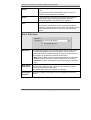
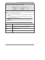
Status
The Status is ‘Active’ when receiving, ‘Waiting’ when inactive and ‘Error’ when a
problem occurs.
Blocks
The number of Blocks indicates the data captured. As a Block is 256 bytes, you
can estimate the amount of data captured and exit the process when required.
Exit
At any time you can select ‘Exit’ to stop the capture process. This will close the
file at that point.
Once a data file has been captured you can use it repeatedly within the Environment
Editor. Refer to ‘Loading a Sample of the Printstream Data’ on page 32 and
‘Creating/Editing Model Printstream Data’ on page 45.
38
The Paris Designer Reference Manual
Chapter 1: Functions in the Environment Editor File Menu
H OW DO I
CAPTURE DATA FROM A
N OVELL PRINT QUEUE ?
The Paris Spooler can receive input directly from a Novell print queue. Again, in
order to ensure that the environment you design is configured for ‘live’ data, you
will need to capture a sample of the print file to disk from the appropriate input
(Novell) queue.
The method is similar to capturing data from a serial port, except that a Novell
queue is selected.
NOTE:
1. It is recommended that you dedicate a ‘Test’ queue for Design/Capture
purposes.
2. So that Paris can input from a Novell queue the current User name
must be defined as the Server. In most cases the production print queue
will be defined with the Spooler’s user as the server.
Refer to Appendix B, Creating and Preparing Novell Print Queues for Input into
Paris.
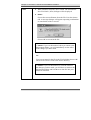
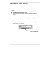
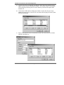
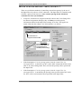
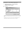
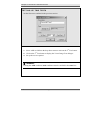
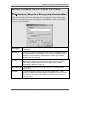
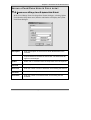
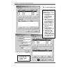
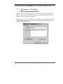
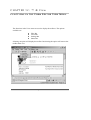
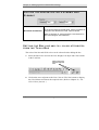
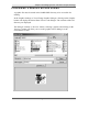
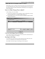
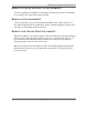
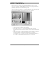
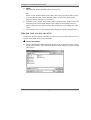
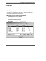
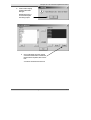
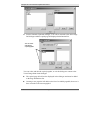
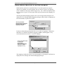
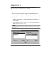
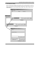
To capture data from a Novell print queue:
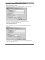
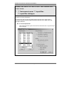
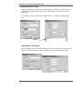
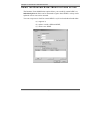
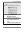
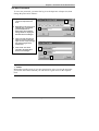
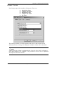
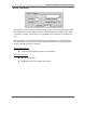
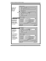
1. Choose the Capture Data option from the Data sub-menu. The Select Input
Source for Data Capture dialogue will be displayed.
39
The Paris Designer Reference Manual
Chapter 1: Functions in the Environment Editor File Menu
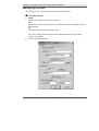
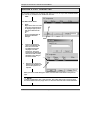
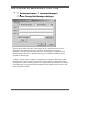
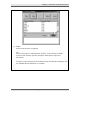
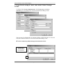
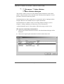
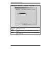
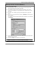
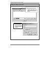
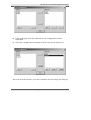
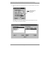
2. Select the required Novell print queue from the drop-down menu. If present, a
list of queued print files will be displayed.
(If a queue is selected that does not have the current Novell username as the
server, an error ‘Unable to initialize input’ will be encountered.)
NOTE:
Novell print queues will only be displayed if you have the Novell client 32 bit
netware on your PC.
Paris will automatically detect available Novell queues. If none are detected, the
only option available in the drop-down menu will be Serial Port and LPD.
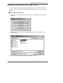
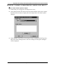
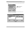
3. Select the
required print file
from the list.
3. Select the required print file from the list, then choose ‘OK’. The Select/Enter
Save File Name dialogue will be displayed.
40
The Paris Designer Reference Manual
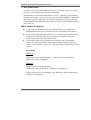
Chapter 1: Functions in the Environment Editor File Menu
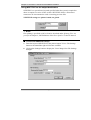
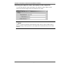
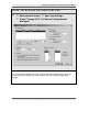
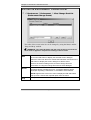
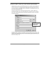
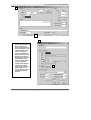
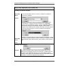
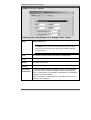
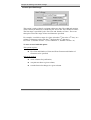
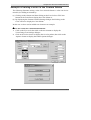
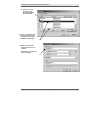
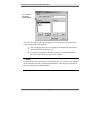
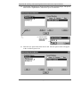
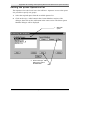
Defining the destination file name for data to be
captured from a Novell queue
The default path displays the DTA directory as the location in which to store the
sample file. It is recommended to always use the default destination.
4. Either:
Select a file from the File List to overwrite an existing file, (a warning
message will appear),
Or:
Type the new file name in the ‘File name’ box (with a .DTA extension).
File name entered
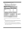
Capturing the data from the queue
5. Choose Save. The File Capture/Transfer dialogue will be displayed and the
capture process will begin immediately. (If the current Novell username is not
defined as being the server, an error message ‘Unable to Initialize Input’ will
be displayed and the capture will abort.)
In the File Capture/Transfer dialogue, the destination directory and filename
will be displayed in the ‘Name’ box in the dialogue. The ‘Status’ of the
capture will be displayed and the number of ‘Blocks’ captured.
41
The Paris Designer Reference Manual
Chapter 1: Functions in the Environment Editor File Menu
Status
The Status is ‘Active’ when receiving, ‘Waiting’ when inactive and ‘Error’ when a
problem occurs.
Blocks
The number of Blocks indicates the data captured. As a Block is 256 bytes, you
can estimate the amount of data captured and exit the process when required.
Exit
At any time you can select ‘Exit’ to stop the capture process. This will close the
file at that point.
Once a data file has been captured you can use it repeatedly within the Environment
Editor. Refer to ‘Loading a Sample of the Printstream Data’ on page 32 and
‘Creating/Editing Model Printstream Data’ on page 45.
42
The Paris Designer Reference Manual
Chapter 1: Functions in the Environment Editor File Menu
HOW
DO
I
C AP TU R E D ATA F R O M AN
LPD QUEUE?
If you have created a job definition in which you have defined an LPD Queue as
the input source in the Spooler (refer to Chapter 2 of the Paris Spooler Technical
Manual), you can capture a data file from the LPD queue.
To begin with, on your host computer, create a test file and configure your LPR
(with the test file) to go to the Paris LPD Queue.
To select LPD as the Input Source for Data Capture:
1. Choose the Capture Data option from the Data sub-menu. The Select Input
Source for Data Capture dialogue will be displayed.
2. Select LPD as the input source from the Type drop-down menu, then choose
OK. The Select/Enter Save File name dialogue will be displayed.
43
The Paris Designer Reference Manual
Chapter 1: Functions in the Environment Editor File Menu
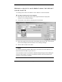
To create a destination file name:
1. Enter a name in the ‘File’ text field with a .DTA extension, for example,
TEST3.DTA (the path name will default to \PARIS\DTA).
2. Choose Save. The LPD Log will be displayed.
3. From your host computer send the LPR. The LPD Log on your PC will reflect
the reception of the data which will be sent to the destination file name in the
PARIS\DTA directory.
4. Close the LPD server when finished.
Once a data file has been captured you can use it repeatedly within the Environment
Editor. Refer to ‘Loading a Sample of the Printstream Data’ on page 32 and
‘Creating/Editing Model Printstream Data’ on page 45.
44
The Paris Designer Reference Manual
C R E AT I N G / E D I T I N G M O D E L P R I N T S T R E A M
D ATA
File menu
Data
Edit Data
Edit Data File dialogue
When designing an environment, in the majority of cases you will need to work with an
accurate sample of the actual printstream. In some cases, however, data does not exist
and a model printstream will need to be created which can then be used to help design
the application which will generate the actual printstream.
C R E ATI N G
A M O D E L O F TH E P R I N TS TR E AM D ATA
The Edit Data function is used to create a model printstream data file. Your model
printstream can contain all the parameters you have in your larger print files. Once
created and saved in the Edit Data File dialogue, your data file can be loaded into
the Environment Editor, divided into text blocks and have other elements added to
test its modeling parameters.
If further changes are required, the file can be reloaded into the Edit Data File
dialogue and edited as required.
EDITING
A S AM P L E O F TH E AC TU AL P R I N TS TR E AM
The Edit Data function can also be used to edit a sample of the actual printstream to
simulate any conditions that may be required in your larger print files. The file can be
displayed in Text View or Hex View.
In the same way as the model printstream, the edited sample printstream can be
saved and loaded into the Environment Editor for testing then reloaded into the
Edit Data File dialogue if further changes are required.
FILE
SIZE IN THE
E D I T D ATA
FUNCTION
The Edit Data function has a file size limit of 32,000 characters. If you attempt to
load a file greater than 32,000 characters, you will be prompted with a dialogue
that gives you the option to truncate the file.
If you accept the truncate option, the first 32,000 bytes of the file will be loaded.
Your original file is not overwritten unless you choose to do so by using the Save
option in the Edit Data file dialogue.
45
The Paris Designer Reference Manual
Chapter 1: Functions in the Environment Editor File Menu
USING
TH E K E Y B O AR D I N TH E
FUNCTION
E D I T D ATA F I L E
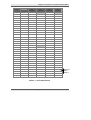
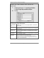
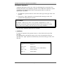
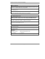
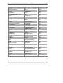
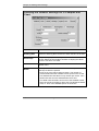
The table below shows the keys that can be used when editing in the Edit
Data File dialogue. Entered text can be blocked and copied, cut and pasted
and deleted.
Key
46
Result
Left arrow
Forward one character
Right arrow
Back one character
Up arrow
Up one line
Down arrow
Down one line
Page Up
Page Upwards
Page Dn
Page Downwards
Home
Start of line
End
End of line
Ctrl+X
Cuts selected text
Ctrl+C
Copies selected text
Ctrl+V
Pastes text that has been cut or copied
Ctrl+Z
Undo Clear
Del
Deletes next character or deletes
selected text
Backspace key
Deletes previous character
The Paris Designer Reference Manual
Chapter 1: Functions in the Environment Editor File Menu
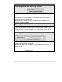
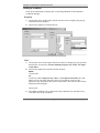
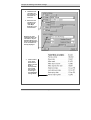
C R E ATI N G
A M O D E L P R I N TS TR E AM D ATA F I L E
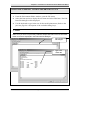
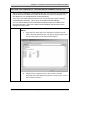
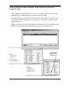
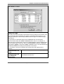
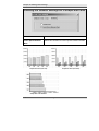
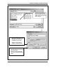
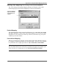
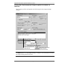
To create a model printstream in the Edit Data File dialogue:
1. From the Environment Editor window, open the File menu.
2. Select the Data option to display the sub-menu and select Edit Data. The Edit
Data File dialogue will be displayed.
3. Use the keyboard to type in the text for the model printstream. (Refer to the
previous page for a description of the available editing keys).
NOTE:
Make sure you have not previously loaded a sample data file into the Environment
Editor as it will be displayed in the Edit Data File dialogue.
47
2.
Open the Edit Data
File dialogue
3.
Type in the
model data
The Paris Designer Reference Manual
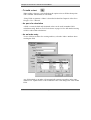
Chapter 1: Functions in the Environment Editor File Menu
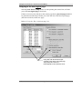
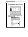
Save
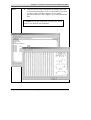
4. To save the file you have created, select the Save button to
display the Select/Enter Save File Name (.DTA) dialogue. You
can choose the required view of the files (list, details etc.) by
clicking on the View Menu icon in the header of the dialogue.
5. Either:
Type a new name for the file in the File field (give the file a
.DTA extension),
or:
To overwrite an existing file, choose the filename from the File
List. The filename will appear in the Selected File field.
6. Choose Save. The file will be saved to the PARIS/DTA default
directory.
Close
48
Choose this button to exit the Edit Data File dialogue and return to the
Environment Editor. To load your model printstream file into the
Environment Editor and create an environment, use the Open Data
option in the File menu.
The Paris Designer Reference Manual
Chapter 1: Functions in the Environment Editor File Menu
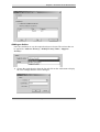
EDITING THE CURRENTLY LOADED MODEL/SAMPLE DATA FILE
After you have created your model printstream file, your next step is to load the file
into the Environment Editor and create an environment for the model data. This
also applies to your sample data file of the printstream.
Once you have created the environment, you may find that you wish to edit the
model/sample printstream. This is done via the Edit Data File dialogue.
You can edit the data file in the Edit Data File dialogue while it is loaded in the
Environment Editor, return to the editor and immediately view the effect of the
changes you have made.
Edit Data
To edit the sample data file currently loaded in the Environment
Editor:
1. Open the File menu and select Edit Data from the Data sub-
menu. The Edit Data dialogue will appear, displaying the data
file currently loaded in the Environment Editor.
2. Edit the file as required (refer to the section Using the
keyboard in the Edit Data File function on page 46 for a list of
the available edit keys).
49
The Paris Designer Reference Manual
Chapter 1: Functions in the Environment Editor File Menu
Save
3. When finished, select the ‘Save’ button. The Select/Enter
Save File Name (.DTA) dialogue will be displayed.
4. Either:
Choose the current filename from the File List, then choose
OK. A message dialogue will appear requesting confirmation
or cancellation of the overwrite.
Choose OK to overwrite the file.
NOTE: If you use this method, when you return to the
Environment Editor, you will immediately see the effect
of the changes you have made.
Or:
Type a new name for the file in the File field then choose OK.
The new file will be saved to the source directory.
NOTE: If you use this method, to view the effect of
the changes you have made, you will have to return to the
Environment Editor and load the new data file into your
model environment.
50
The Paris Designer Reference Manual
Chapter 1: Functions in the Environment Editor File Menu
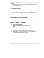
Close
6. Choose Close to exit the Edit Data File dialogue and return
to the Environment Editor. You can repeat the process until
you have achieved all the conditions in your model
printstream that you wish to apply to your main printstream
files.
NOTE: If you click on the Hex View tab, you will be
able to view the data in hexadecimal
51
The Paris Designer Reference Manual
Chapter 1: Functions in the Environment Editor File Menu
L O AD I N G A M O D E L / S AM P L E
D ATA F I L E D I AL O G U E
D ATA F I L E I N TO TH E
EDIT
The Load button in the Edit Data File dialogue is used to load a data file from
the PARIS/DTA directory. For example, you could use this method to load and
edit a model or sample data file for which you have already created an
environment.
You cannot view the effect of any changes you make until you save the file, exit
the Edit Data File dialogue then load the edited file into the Environment Editor.
Refer to the previous section ‘Editing a model data file’.
Load
To open a data file into the Edit Data File dialogue:
1. Select the Load button to display the Select/Enter File To Load
(.DTA) dialogue.
2. Select the required file from the File list, then choose OK. The
file will be loaded into the Edit Data File dialogue. You can
view and edit the file in Text View (ASCII) or Hex View
(Hexadecimal) by selecting the appropriate tab.
Save
3. Edit the file as required, then click on the Save button to save
the file.
4. Either:
Type a new name for the file in the File field then choose Save.
Or:
Choose the current filename from the File List, then choose
Save. A warning will appear requesting confirmation of the
overwrite. Choose OK to overwrite the file.
Close
5.
Click on the Close button to return to the Environment Editor.
6. To load your model printstream file into the Environment Editor
and create an environment, use the Open Data option in the File
menu.
52
The Paris Designer Reference Manual
P R I N T I N G A P R O O F O F T H E C U R R E N T PA G E
File menu
Print
Alt + P
The ‘Print’ option in the File menu is used to print a proof of the page that is
currently displayed on your screen. The proof print will contain all form and
environment elements that have been created. For example, when you have created
an environment and form for your sample data, you could use this option to view a
hard copy of the document.
Choosing Print from the File menu (or using the shortcut keys Alt+P), will print
the current page and form of your environment on the printer currently selected for
your PC.
The proof page will print from the current input tray, however Duplex functions
will not be honored.
NOTE
Refer to the following section re selecting the print destination for the proof print.
To print a proof of the current page:
1. Display the page to be printed on-screen.
2. Choose Print from the File menu. The page currently displayed will be sent to
the printer selected for your PC.
53
The Paris Designer Reference Manual
S E L E C T I N G A P R I N T D E S T I N AT I O N
File menu
Select Printer
Select Printer dialogue
This option is used to select one of the defined print destinations as the current
printer. All proof prints will be directed to the currently selected printer. It is not
possible to select more than one printer.
Print destinations are those output devices available to the PC running the
Designer that have been added to the list of print destinations. Print destinations
are added via the View/Change Printers dialogue. (Refer to ‘Adding, Modifying
and Removing a Print Destination’ on page 55).
To print to a selected print destination:
1. Choose Select Printer from the File menu. The Select Printer dialogue will be
displayed.
2. Choose the required print destination from the list then choose OK.
The Paris Designer Reference Manual
54
A D D I N G, M O D I F Y I N G A N D R E M O V I N G A P R I N T
D E S T I N AT I O N
File menu
Modify Printers
View/Change Printers dialogue
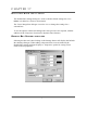
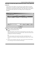
To add or modify a print destination, the Modify Printers option is selected from
the File menu to display the View/Change Printers dialogue. When Paris is first
installed, a default printer driver is supplied (Generic PCL5) and is displayed in
the list of printers in the View/Change Printers dialogue.
In the View/Change Printers dialogue, either select the Add button or right-mouse
click on a printer to display the pop-up menu and choose Add. The View/Change
Printer dialogue will be displayed.
55
The Paris Designer Reference Manual
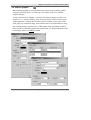
Chapter 1: Functions in the Environment Editor File Menu
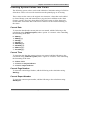
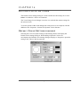
AD D I N G
A PRINTER
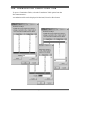
The View/Change Printer dialogue is used to add a print destination and define the
added printer’s attributes, resource management capabilities and print image
positioning (physical page shift).
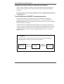
The dialogue is divided into three sections:
Printer,
Resources,
Physical Page Shift.
56
The Paris Designer Reference Manual
Chapter 1: Functions in the Environment Editor File Menu
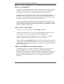
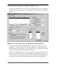
Printer Attributes
The Printer section of the dialogue deals with the printer attributes.
Enter printer
‘File Name’ and
‘Full Name’
A printer is given a ‘File Name’ and a ‘Full Name’. Both names must be entered
and each is entered in the relevant box in the View/Change Printer dialogue.
File Name
The ‘File Name’ (default setting NEWPRT) is used to identify the printer in the
Paris system and must be a valid DOS filename, up to 8 characters and must also
be unique.
For example MRKTL3
Full Name
The ‘Full Name’ is displayed in the Printer list in the Select Printer and
View/Change Printers dialogues. The default setting is NEW_PRINTER.
Up to 16 characters can be used. Spaces are allowed.
For example: Marketing L3
57
The Paris Designer Reference Manual
Chapter 1: Functions in the Environment Editor File Menu
Printer Type
The ‘Type’ field displays the default printer driver. The Type refers to the physical
printer to which formatted output is to be directed and is displayed with the
printers Full Name in the Select Printer and View/Change Printers dialogue.
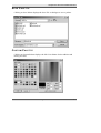
The printer type is selected from the ‘Type’ drop-down list in the View/Change
Printers dialogue.
The printers available in the list vary according to the configuration of the PC on
which the Spooler is running. Usually the list is broken into three general types
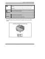
differentiated by small graphic symbols as follows:
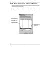
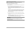
•
HP-PCL type printers, indicated by the BLUE HP symbol.
•
Adobe Postscript printers, indicated by the RED stylized Adobe ‘A’.
•
Available Windows devices, indicated by the Windows symbol.
HP Symbol
Adobe ‘A’
Windows Symbol
How is the Printer Type List created?
When you add a print destination to Paris, the printer type is selected from a list of
printer (output device) drivers in the ‘Type’ drop-down menu. The printer drivers
in the list vary according to the configuration of the PC on which Paris is running.
The printers displayed in the list are a result of two searches the software
performs:
1. The software checks the /PARIS/PRT directory to see what XPD (XLPrint
Printer Description) files are present.
2. The software queries Windows as to what printer (or device) drivers have been
loaded. This allows the Spooler to format for any Windows GDI supported
device, for example Fax drivers or PDF drivers.
58
The Paris Designer Reference Manual
Chapter 1: Functions in the Environment Editor File Menu
What are XPD Files?
XPD files are the way Paris describes the features of the printer. They work either
as standalone files, in the case of HP-PCL printers, or in combination with PPD
(Postscript Printer Description) files, in the case of Adobe Postscript printers.
In general terms XPD files are created and supplied by your distributor. PPD files
are those files supplied by the Printer manufacturer. An XPD for a PostScript
printer simply contains a reference to include a corresponding PPD file in the
XPD.
NOTE:
XPD files contain command options to manage printer resources. These options
enable you to tailor Paris resource management for the particular requirements of
your printer. Refer to the section XPD Resource Management Commands for PCL
and PostScript printers on page 71.
WARNING!
Both XPD and PPD files are text files and can be edited using a standard text
editor, however, it is recommended that these should NOT be changed except by
experienced users or under instructions from the distributor.
59
The Paris Designer Reference Manual
Chapter 1: Functions in the Environment Editor File Menu
Windows GDI supported devices
When using GDI to print there are important points to be considered. Firstly, GDI
was not really designed as a production printing method. As a result, it is not
optimized for speed and can struggle to keep up with high speed printers.
Secondly, when using GDI, Paris is passing responsibility for the final output over
to Windows and in turn the manufacturer supplied GDI driver. As a result, the
outcome cannot be guaranteed to print exactly as intended. There could be font
substitutions or incomplete support for some of the Paris features, because the
printer is incapable of imaging the page as originally designed.
How do XPD and PPD files work?
XPD (XLPrint Printer Description) files are the way Paris describes output
destinations. XPD files are a superset of the Adobe PPD (PostScript Printer
Description) files used to describe the features of PostScript output devices.
What is the purpose of an XPD file?
An XPD file serves a dual purpose in the Designer:
• First, it makes the various printer features described in the XPD file available in
the editor. For example, if a printer has support for 10 different page sizes, the
XPD file makes this information available in the editor.
• Second, the task of an XPD file is to put the appropriate instructions into the
output file to call the features that are on the printer.
PostScript printers also use XPD files. In this case the XPD is really just a pointer
to the appropriate PPD file. Normally an XPD file for a PostScript printer contains
a single line which simply incorporate the PPD files into the XPD.
What is the purpose of a PPD file?
Devices that contain PostScript interpreters may contain a wide variety of features
such as different page sizes, different methods of paper handling; the type of fonts
available and so on. Not all devices have the same set of features, nor are these
features called up in the same way.
PPD (PostScript Printer Description) files are text files that have the purpose of
providing a uniform approach to using the features of such devices.
60
The Paris Designer Reference Manual
Chapter 1: Functions in the Environment Editor File Menu
How do PPD files provide this uniform approach?
An output device that contains a PostScript interpreter has an associated PPD file.
When such an output device is made accessible to a host computer, the PPD file is
stored on the host computer. The applications on the host computer can then
determine the available features on a device by interrogating the associated PPD
file.
How does an application interrogate a device’s PPD file?
There is no need for an application to understand the device’s features as PPD files
contain structures that allow this interrogation. From the list of features found in
selected device’s PPD file applications can then build a user interface.
To summon each feature, the PPD file also contains the PostScript language code.
When a user selects a feature, such as manual feed or duplex printing, the code for
each selected feature is extracted from the PPD file. This code is included in the
appropriate place in the output file before the output file is sent to the device. (In
this case, the output file refers to the file having the PostScript language
description of the document created by the user.)
What is the availability of XPD and PPD files?
During installation, some XPD and PPD files are copied to your system. If you
require further XPD or PPD files, contact your Paris distributor.
Refer also to the section XPD Resource Management Commands for PCL and
PostScript printers on page 71.
61
The Paris Designer Reference Manual
Chapter 1: Functions in the Environment Editor File Menu
Rebuilding the Printer Type List
Paris maintains a list of available printers. It is this list that contains the PCL and
Adobe printer entries that are shown in the Printer Type drop-down menu.
The list must be kept up-to-date, as the number of printer types supported by Paris
will constantly grow as new printers are released on the market. That is the
purpose of the Rebuild Printer List button that is within the View/Change Printer
dialogue.
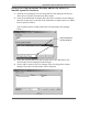
To support the features of a new printer:
1. Place the distributor supplied XPD and\or PPD files in the PARIS/PRT
directory.
2. Once the new files have been added, choose Modify Printers from the File
menu to open the View/Change Printers dialogue.
3. Choose the ‘Add’ button to open the View/Change Printer dialogue and click
on the Rebuild Printer List button to make the printers available to the
software.
Selecting the button causes the software to scan the directory and update the
list with any new entries. If no new XPD\PPD files have been added the
existing list will not be changed.
2.
62
Click on the Rebuild Printer
List button to make added XPD
or PPD files available to the
software.
The Paris Designer Reference Manual
Chapter 1: Functions in the Environment Editor File Menu
Defining the Output destination
Part of the printer definition is to instruct the software where to send the output
once it has been formatted. The output destination is entered in the ‘Output To’
box.
NOTE:
If the printer (or device) driver selected is a Windows GDI device, the Output To
option is not available. Refer to the previous section ‘Printer Type’ on page 58.
Output can be directed to physical LPT ports, for example, LPT1, LPT2. These
may be directly connected to the printer or possibly re-mapped to go to Novell
print queues or a TCP/IP address.
The queue name for output directed to a Novell queue is entered into the box or, if
to a disk file, the destination drive, directory and file name is entered into the box
(for example: D:\OUTPUT\OUT.DTA).
63
The Paris Designer Reference Manual
Chapter 1: Functions in the Environment Editor File Menu
Using NEXTFILE as the output destination
NEXTFILE is a special Paris keyword specified when the system is required to
direct its output to a series of files on disk. NEXTFILE allows a file name or
extension to be incremented to avoid overwriting previous files.
NEXTFILE settings are printer bound, not global.
NOTE:
File splitting is specified at job level and is described under Splitting Files in a
print job in Chapter 2, Job Definitions of the Paris Spooler Technical Manual.
To define the NEXTFILE settings:
1. Enter the keyword NEXTFILE in the printer Output To box. The Settings
button to the immediate right will become available.
2. Click on the Settings button to display the View/Change Next File Settings
dialogue.
64
The Paris Designer Reference Manual
Chapter 1: Functions in the Environment Editor File Menu
Settings
Under the Settings section of the dialogue are the text fields Output directory;
Output Name; Output extension. Next to each text field is a drop-down menu
which lists the options that can be used for the Output directory, file name or file
extension (each menu is the same for each output setting).
Output directory
In the Output Directory text field, specify the directory to which you want the files
to be written, or select a name from the drop-down menu.
65
The Paris Designer Reference Manual
Chapter 1: Functions in the Environment Editor File Menu
Output name
In the Output Name text field, either type in the name of the file required, or
choose a name from the menu.
•
The entries <@INPUT> or <INPUT> are equally valid. Either passes the name
of the input file through to output and applies to disk based input only.
•
<fieldname> where a field name is entered in the angled brackets, uses the
contents of the nominated field for the output file name,
•
The LPR control file can be scanned and any of the following entries can be
extracted and used for the output filename:
- <@LPR_HOST>
- <@LPR_USER>
- <@LPR_CLASS>
- <@LPR_JOB>
- <@LPR_INPUT>
- <@LPR_INPUT_PATH>
- <@LPR_INPUT_NAME_
- <@LPR_INPUT_EXTN>
- <@LPR_TITLE>
Output extension
In the Output extension text field, either type in the name of the file required, or
choose a name from the menu (as above)
Once the filename and extension are specified you can choose to increment either
of them.
Maximum File Number
In the Maximum File Number text field, enter the maximum file number required.
66
The Paris Designer Reference Manual
Chapter 1: Functions in the Environment Editor File Menu
Appending the Number to the file name or extension
Append the Number to ‘Name’
To increment the file name, select the Append Number to ‘Name’ checkbox.
For example, as per the dialogue above, the resultant files would be
PRINT001.OUT, PRINT002.OUT and so on.
Append Number to ‘Extension’
To increment the file extension, select the Append Number to ‘Extension’
checkbox.
For example, as per the dialogue above the resultant files with be PRINT.001,
PRINT.002, PRINT.003 and so on.
67
The Paris Designer Reference Manual
Chapter 1: Functions in the Environment Editor File Menu
Retaining the input file name and number for the output file
To retain the input file name and number, the character string <input> can be
entered in both the Output Name and Extension text fields.
NOTE:
<input> can also be entered as the Directory name, however this would result in
the overwriting of the input files by the output files and should only be used with
caution.
68
The Paris Designer Reference Manual
Chapter 1: Functions in the Environment Editor File Menu
M AN AG I N G P R I N TE R R E S O U R C E S
The Resources section of the View/Change Printers dialogue deals with printer
resource management. (The Id number is the internal identifier used by Paris for
that set of printer resources and cannot be edited.)
How Paris manages printer resources
Resource management, the downloading of fonts, forms and graphics to the
printer, is automatically controlled by Paris, but varies according to the capabilities
of the device and Page Description Language (PDL) being used. There are four
general levels of resource management:
I. Printers with permanent storage available.
Paris is capable of permanently storing the font resources of some printers.
For these printers, when a resource is first sent to the printer, Paris sets a flag to
indicate the resource is permanently stored and it is not sent again unless
specifically instructed. (For full details of which printers are currently supported,
contact your distributor.)
II. PCL printers (no permanent storage).
When printing to PCL printers (those with no permanent storage), Paris uses its
resource flag system to indicate that resources are stored in the printers memory.
Because this is memory-based storage, these resources are lost if the printer is
turned off, or overwritten if another application sends output to the printer.
If the printer is turned off or reset, you must use the ‘Reset at start of next job’
option in the Paris Spooler to reset the flags to their initial state. Also, if the printer
is being shared with other applications, (e.g. for word-processing), Paris must be
instructed to reset the resources at the beginning of each job. This naturally means
the resources will be sent every time the job is printed and has the effect of
increasing the transmission time to the printer.
Refer to the section XPD Resource Management Commands for PCL and
PostScript printers on page 71.
69
The Paris Designer Reference Manual
Chapter 1: Functions in the Environment Editor File Menu
PCL4 printers
PCL4 printers are not supported by Paris.
NOTE:
Paris provides you with the option to control the number of characters downloaded
in a character set. This may be necessary if you are using a printer that requires the
resources to be sent every time a job is printed. Refer to Appendix A, ‘Modifying
the Character Selection Table’ of the Paris Spooler Technical Manual.
III. PostScript printers (no permanent storage)
As part of its job end processing, Postscript printers go through a clean-up. As a
result, when printing to PostScript printers (those with no permanent storage),
Paris must send all resources required for a job at the beginning of each job. Refer
to the section XPD Resource Management Commands for PCL and PostScript
printers on page 71.
IV. Windows GDI
When printing using a manufacturer supplied GDI driver, Paris passes total
responsibility for the downloading and management of resources to Windows.
WARNING!
Windows GDI does not understand bitmap fonts. If the application contains bitmap
fonts, Windows passes the information to the driver. It is up to the printer driver to
provide a solution to managing the fonts.
Note also that bitmap fonts will not appear in the Font List if a GDI printer driver
is selected. Refer to Chapter 20, ‘Using the Font List function’ of this manual and
‘Adding a font to the font list’ in Chapter 11 of the Paris Designer User’s Manual.
70
The Paris Designer Reference Manual
Chapter 1: Functions in the Environment Editor File Menu
XPD Resource Management Commands for PCL and
PostScript printers
XPD files contain command options to manage printer resources. These options
enable you to tailor Paris resource management according to the particular
requirements of your printer. Some Paris supplied XPDs have these entries already
added.
WARNING!
XPD files can be edited using a standard text editor, however changing XPDs
without proper instruction can be detrimental. It is recommended that XPD files should
NOT be changed except by experienced users or under instructions from the
distributor. A full description of the working of XPD and PPD files can be found on
page 60.
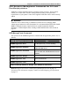
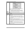
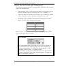
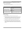
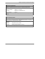
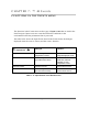
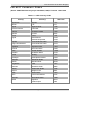
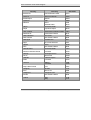
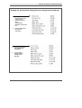
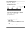
XPD ManageFonts Command
The options for the XPDManageFonts command and the applicable printers are as
follows:
XPD ManageFonts Command
Use
*XPDManageFonts: None
For Docuprint only, no font handling.
*XPDManageFonts: Harddisk
For 4517, 4220, 4230 printers. Downloads
to the hard disk once.
*XPDManageFonts: Download
For PCL and PostScript printers which
have no hard disk. Downloads the fonts as
needed.
*XPDManageFonts: Always
Default for Post Script.
*XPDManageFonts: True
Same as Download.
*XPDManageFonts: False
Same as None.
NOTE: PostScript defaults to ‘Always’. PCL defaults to ‘Download’.
Refer to: Support for Printer resident fonts (PostScript) in Paris on page 74,
Substitution file information on page 75 and Font Name Mapping file information
on page 75.
71
The Paris Designer Reference Manual
Chapter 1: Functions in the Environment Editor File Menu
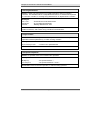
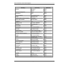
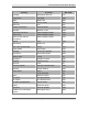
XPD ManageForms Command
The options for the XPDManageForms command and their use are as follows:
XPD ManageForms Command
Use
*XPDManageForms: None
For Docuprint only, no form handling.
*XPDManageForms: Harddisk
For 4517, 4220, 4230 printers. Downloads to
the hard disk once.
*XPDManageForms: Download
for PCL and PostScript printers which have
no hard disk. Downloads the forms as needed.
*XPDManageForms: Always
Default for Post Script.
*XPDManageForms: True
Same as Download.
*XPDManageForms: False
Same as None.
NOTE: PostScript defaults to ‘Always’. PCL defaults to ‘Download’.
XPD ManageGrafs Command
The options for the XPDManageGrafs command and their use are as follows:
XPD ManageGrafs Command
Use
*XPDManageGrafs: None
For Docuprint only, no graphic handling.
*XPDManageGrafs: Harddisk
For 4517, 4220, 4230 printers. Downloads to
the hard disk once.
*XPDManageGrafs: Download
For PCL and PostScript printers which have
no hard disk. Downloads the graphics as
needed.
*XPDManageGrafs: Always
Default for PostScript printers.
*XPDManageGrafs: True
Same as Download.
*XPDManageGrafs: False
Same as None.
NOTE: PostScript defaults to ‘Always’. PCL defaults to ‘Download’.
72
The Paris Designer Reference Manual
Chapter 1: Functions in the Environment Editor File Menu
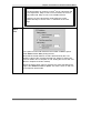
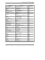
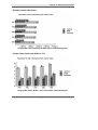
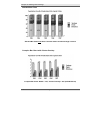
XPD Graphics Compression commands
Paris offers you the option to compress graphics using XPD Graphics Compression
commands. Using graphics compression will make the output files created by Paris
considerably smaller, an important benefit when color applications are involved.
Using XPD Graphics Compression commands
Graphics compression is activated in Paris via an XPD entry in the XPD file as
follows: *XPDGrafCompression type, where type can be either None; RLE or
Flate. Using either RLE or Flate invokes the graphics handling system.
None
Using ‘None’ restores the original Paris graphics handling system. The benefit of
size reduction to output files is not available using this type.
RLE
Using RLE achieves a 20% reduction in size of simple images (e.g. black and
white), less on color graphics (only 1% - 2% in some cases).
RLE can be used with PostScript Level 2 printers and up. It has little effect on
increasing Paris Engine throughput.
Flate
Flate uses Zlib flate/deflate compression and can be used with PostScript Level 3
printers only. It is effective with all types of graphics, with compression typically
around 65% on color images and 85% on simpler images, such as black and white.
Flate has significant effect on increasing Paris Engine throughput. (NOTE: It is
recommended that *XPDManageGrafs: Download is used with Flate so that
graphics are compressed at the beginning of the job, thus avoiding the need for
graphics to be compressed every time they are used.)
For example, to enable zlib deflate/flate compression, the following line would be
added to the XPD: *XPDGrafCompression: Flate
If the XPDGrafCompression keyword is not present within the file, then the
default is None.
73
The Paris Designer Reference Manual
Chapter 1: Functions in the Environment Editor File Menu
Support for Printer resident fonts (PostScript) in
Paris
Paris supports calling resident fonts from a printer. There are two main activities
when working with resident Type 1 fonts.
•
Selecting the font in the Designer, and
•
Printing with the font.
Using Type 1 PostScript fonts under Windows also involves encoding changes to
resolve problems caused by international characters and differences between the
Windows default character map and the font’s internal mapping.
Refer to the previous section XPD Resource Management Commands for PCL and
PostScript printers on page 71.
Substitution and Font Name Mapping files
To support resident fonts, Paris contains several files including the Substitution
file and the Font Name Mapping file.
The Substitution file details what alternative font to use as a screen font and the
width table if a requested font is not available.
The Font Name Mapping file is used to find a Windows style name for a given
PostScript font name.
There are two separate files used for both of these areas:
•
The 'base' file is created and maintained by XLPrint Software. The user
should not modify this file. The ‘base’ file may be updated or modified
by reinstalling the Paris software.
•
The second file is the 'user' version of the file, it is freely modifiable by
the user and will not be overwritten when the system is reinstalled or
updated.
This system of 'base' and 'user' files allows us to easily update our basic
information without causing backward compatibility problems for existing users.
74
The Paris Designer Reference Manual
Chapter 1: Functions in the Environment Editor File Menu
Substitution file information
The Substitution file FontSub.xfs is a standard file in XPD format that is created
and maintained by XLPrint Software. The first line of this file is an *Include:
UserSub.xfs. This file (UserSub.xfs) is initially empty, but can be modified by the
user to add new substitutions, or to replace standard substitutions.
Each *XPDFontSubstitution: “family,style=subFamily,subStyle” entry matches
a Windows family name (which can include spaces, but not commas) and style to
another Windows family name and style.
For example:
*XPDFontSubstitution: “Helvetica,Regular=Arial,Regular”
Font Name Mapping file information
The Font Name-Mapping file FontName.xfs consists of entries that map a
PostScript internal name to a Windows name and style. This file is necessary
because PostScript fonts have an internal name which MUST be used when calling
this font from the printer. However, the Windows name for a PostScript font is
often not the same, and this file provides the link. It gives us the mapping between
the PostScript internal name and the Windows name.
The syntax is *XPDFontName postscriptName/Windows family name:
"style".
For example:
*XPDFontName Helvetica-Narrow/Helvetica Narrow: "Regular"
75
The Paris Designer Reference Manual
Chapter 1: Functions in the Environment Editor File Menu
Making a Type 1 font available to Paris
Paris determines the Type 1 fonts that can be used and how to use them when
printing in two slightly different ways, depending upon whether Adobe ATM is
loaded or not.
If Adobe Type Manager® (ATM) is loaded…
A list of available fonts is requested from ATM,
1. The system looks at the currently selected printer,
2. A list of the fonts resident on the printer and for which we can locate a width
table is added to the list from ATM,
3. This printer resident list is created by first cross-referencing the '*font' entries
from the printer's XPD/PPD with the '*XPDFontName' entries from the
'FontName.xfs' file. This gives us the Windows equivalent name and style for
the printer font.
4. This Windows name and style is then checked against the
*XPDFontSubstitution' entries from the 'FontSub.xfs' file.
- If a match is found then we know we can find a width table for this font. The
original windows name and style are then checked against the fonts added by
ATM.
- If there is no match, then this font is added.
The check against the ATM list simply prevents a problem where ATM and the
printer PPD both reference the same font name, such as Helvetica.
If ATM is not loaded…
The list of available Type 1 fonts is built by comparing the Printer resident fonts
with the 'FontName.xfs' and 'FontSub.xfs' files, as in the above process.
76
The Paris Designer Reference Manual
Chapter 1: Functions in the Environment Editor File Menu
Adding a new resident font to Paris
There are 3 ways to make a resident printer font available to Paris.
1. Add a *font entry to the XPD/PPD for the printer. Most manufacturer supplied
PPD files will already contain these entries.
2. Add an *XPDFontName entry to the UserName.xfs file. This maps the
internal name from the *font entry to a Windows family name and style.
If ATM is loaded and can supply a font with the same Windows name and
style as entered, then that is all that needs to be done.
3. Add an *XPDFontSubstitution entry to the UserSub.xfs file that maps the
Windows family name and style values from Step 2 to an existing Windows
family and style.
This step is only required if:
(a) ATM is not loaded, or
(b) ATM is loaded, but does not supply a Windows family name and style to
match the values from Step 2.
WARNING!
XPD files can be edited using a standard text editor, however changing XPDs
without proper instruction can be detrimental. It is recommended that XPD files should
NOT be changed except by experienced users or under instructions from the
distributor.
A full description of the working of XPD and PPD files can be found on page 60.
Printing with resident fonts
If a font has been made available using the above steps, then the Spooler Engine
will recognise it as a resident font during printing, and will not attempt to
download the file.
77
The Paris Designer Reference Manual
Chapter 1: Functions in the Environment Editor File Menu
Suggested setup for using Type 1 fonts within Paris
The best set up for using Type 1 fonts within Paris is:
1. Install Adobe Type Manager® (ATM).
2. Examine the XPD/PPD of the printer to be used for printing, and check the
'*Font' entries. For each '*Font' entry, check or add an entry to the
'FontName.xfs' or 'UserName.xfs' files to establish a connection between the
printer name and the windows name and style.
3. Ensure that ATM has a font with the same windows name and style as each
entry in step 2.
4. If there are 'font' entries that have a '*XPDFOntName' that does not match any
ATM supplied font, then add an '*XPDFOntSubstitution' entry to the
'UserSub.xfs' file to allow Paris to use this font.
With the above setup, all Type 1 fonts that ATM or the printer understands will be
available for use in designing forms and jobs, and any font that the printer has
resident will not used without downloading.
WARNING!
XPD files can be edited using a standard text editor, however changing XPDs
without proper instruction can be detrimental. It is recommended that XPD files should
NOT be changed except by experienced users or under instructions from the
distributor.
A full description of the working of XPD and PPD files can be found on page 60.
78
The Paris Designer Reference Manual
Chapter 1: Functions in the Environment Editor File Menu
PostScript Type 1 Font Re-encoding
Type 1 fonts are normally supplied (in either downloadable or resident versions) as
Adobe 'standard' encoding. This differs significantly from the default Windows
encoding for font characters, mostly above ASCII 128.
Type 1 font designers expect Windows applications (normally the PostScript
driver) to re-encode fonts when sending them to the printer. Re-encoding involves
copying the font to a new name and changing the Encoding entry (an array of 256
character glyph names) to the required encoding. The font is then called by this
new name.
Paris implements re-encoding in two different ways
The main support for re-encoding is a new XPD entry, *XPDFontEncoding:
Standard/ISOLatin1. The default is 'Standard'. This means 'do not re-encode
fonts'.
Although this will produce incorrect output for many fonts if characters above 128
are used, it is the default for backward compatibility with earlier versions of
Paris/Lapres. If the value is ISOLatin1 then Paris will re-encode Type 1 fonts into
the Adobe ISOLatin1 encoding when printing.
1. Re-encoding downloaded Type 1 fonts
Downloaded Type 1 fonts are re-encoded by changing the Standard encoding
vector prior to downloading any fonts. The built-in ISOLatin1 vector is copied
into the Standard vector, so that any downloaded font that calls for the Standard
vector actually gets the ISOLatin1 vector.
2. Re-encoding resident Type 1 fonts
Resident Type 1 fonts are re-encoded according to the Adobe recommendations.
The font is copied to a new name, and the Encoding entry in the new font library
is replaced with the required vector. A resident font is re-encoded only if the
*Font entry in the printer PPD indicates that the font uses the Standard encoding
as a default.
NOTE:
Support for the exact Windows encoding will be added as a new value: WinStandard.
79
The Paris Designer Reference Manual
Chapter 1: Functions in the Environment Editor File Menu
How Paris handles TrueType fonts for PostScript
Printers
When using TrueType fonts in a job being sent to a PostScript printer, Paris
converts the TrueType fonts into bitmap fonts (Type3) before sending them
instream. This technique, although effective and transparent to the user, does have
the effect of increasing the size of the PostScript output file.
In some cases where there is a heavy use of large TrueType fonts in the job, the
amount of font data contained in the output file could actually exceed the amount
of actual data.
Code has been introduced into Paris to eliminate this problem in those cases where
the printer has the required functionality (i.e. a TrueType rasterizer).
As a result of this new code instead of converting each different size and style
TrueType font to a bitmap Paris now sends down a single Type42 outline font per
family.
Paris sends Type42 outline fonts by default
At print time during the normal scan of the printer PPD file the code now looks for
the PPD entry: *TTRasterizer: Type42
This entry indicates that the printer is capable of taking in Type42 fonts. If this
entry is found in the PPD file Paris will automatically send Type42 outline fonts
rather than converting to bitmaps. If the entry is not in the PPD file bitmaps will be
sent. This is now the default function of the Paris software.
Overriding Type42 downloading
If necessary, this function can be overridden and TrueType font handling can be
returned to the bitmap method even if the PPD has the Type42 rasterizer entry.
To turn off Type42 downloading, add the following line into the printer’s XPD
file: *XPDType42: False
WARNING! XPD files can be edited using a standard text editor, however
changing XPDs without proper instruction can be detrimental. It is recommended
that XPD files should NOT be changed except by experienced users or under
instructions from the distributor.
A full description of the working of XPD and PPD files can be found on page 60.
80
The Paris Designer Reference Manual
Chapter 1: Functions in the Environment Editor File Menu
U S I N G B AR C O D E S
IN
P AR I S
Paris offers as an optional extra, the ‘Barcodes Kit’, which can be added to any
installed Paris system. The kit consists of a number of TrueType fonts and
supporting program code that enable Paris to prepare and format barcodes
according to user requirements.
NOTE:
The ‘Barcodes Kit’ must be purchased and installed separately. Contact your
distributor for details.
Simple to Use
The barcode kit is simple to use. A Paris function that allows incoming data to be
recognised and used anywhere in a document also allows application of the
‘Barcodes Kit’ option to format data for printing as a barcode.
Create and Print from any Data
With the ‘Barcodes Kit’, barcodes may be created and printed from virtually any
data. Formatted data can be placed on a page, using any of the standard Paris
methods for adding data to a document, with the required TrueType barcode font
selected as the current font.
Current users of the Paris system will be able to use the ‘Barcodes Kit’ without
additional training.
81
The Paris Designer Reference Manual
Chapter 1: Functions in the Environment Editor File Menu
Supported Barcodes
Barcodes supported by the ‘Barcodes Kit’ are:
• Code 3 of 9.
• Code 93.
• Code 128
• Codabar
• EAN/JAN-8
• EAN/JAN-13
• UPC-A
• UPC-E
• PostNet
• Interleaved 2 of 5
• MSI Plessey
For barcode types that support variable numbers of check digits, a user parameter
is available.
Fonts
Since the ‘Barcodes Kit’ support is based upon a set of TrueType fonts, these fonts
must be available to the PC that runs the Paris Designer or Paris Spooler.
For example, if the Paris Designer is installed on a server in a network, then the
TrueType fonts must be installed on every network workstation that runs the
Designer.
82
The Paris Designer Reference Manual
Chapter 1: Functions in the Environment Editor File Menu
Updating Resources
The Update function in the Resources section of the dialogue only applies to those
printers with permanent storage facilities (see item ‘1’ in the earlier section ‘How
Paris manages printer resources’).
In rare circumstances, such as the hard disk failing on the printer, or a resource
(e.g. font) being accidentally deleted, it may be necessary to instruct Paris to
download these resources again.
Clicking on the Update button will display the View/Change Resource Flags
dialogue which gives you access to the individual Paris resources.
The dialogue permits the user to select the necessary resource(s) to be updated
and turn off the permanent download flag. This means the next time a job is set for
printing, the selected resource(s) will be sent to the printer.
83
The Paris Designer Reference Manual
Chapter 1: Functions in the Environment Editor File Menu
To update a resource:
1. Click on the Update button to open the View/Change Resource Flags dialogue.
2. Select the type of resource required from the drop-down menu (Forms, Fonts
or Graphics).
A list will be displayed of all the resources of this type that Paris has flagged
as being permanently stored on the printer.
3.
Highlight the
required
resources to
reset the flag.
3. Highlight the resource or resources on which you require to have the flag set to
‘OFF’.
4. Click on Clear. The internal flags for the selected resources will be
automatically set to ‘OFF’.
5. Click on Exit.
NOTE:
Flags are set to ‘OFF’ only when the Clear button is selected.
The next time an application that requires these resources is run they will be sent
to the printer and the download flag will be set to ‘ON’ again.
84
The Paris Designer Reference Manual
Chapter 1: Functions in the Environment Editor File Menu
Resetting Resources
The Reset options allow the user to instruct Paris when to reset the printer. The
options in the drop-down menu are ‘Never’, ‘At Job’ Start’ and ‘At System Start’.
The option chosen depends on the storage capabilities of the printer being defined
and whether or not the printer is being shared with other applications. These are
described as four general levels of resource management in the section ‘How Paris
manages printer resources’ on page 69.
Choosing a Reset option
(A) Printers with permanent storage facilities
• If you are defining a printer with permanent storage facilities, you would
choose ‘Never’.
If it necessary to instruct Paris to download the resources again for this printer,
you would use the Update button. Refer to Updating Resources on page 80.
(B) PCL printers (no permanent storage)
• If you are using a PCL printer with no permanent storage facilities that is
NOT being shared with other applications you would choose ‘Never’.
However, if the printer is turned off or reset, you would have to modify the
printer definition and select the ‘Reset at start of next job’ checkbox. This
causes the Spooler to reset the resources at the beginning of the next job. Once
the resources are sent, the ‘Reset at start of next job’ option is canceled.
85
The Paris Designer Reference Manual
Chapter 1: Functions in the Environment Editor File Menu
•
If you are using a PCL printer with no permanent storage facilities that IS
being shared with other applications you would choose ‘At Job Start’. This
will cause the Spooler to reset the resources at the start of each job (as the
resources are overwritten if another application sends output to the printer).
•
If you are using a PCL printer with no permanent storage facilities as a
dedicated printer you would choose ‘At System Start’ to reset the resources
each time the system is started.
(C) PostScript printers (no permanent storage)
• If you are using a Postscript printer with no permanent storage facilities the
option chosen will be irrelevant as Paris must send all the resources required
for a job at the beginning of each job.
Media Mapping
Media Mapping is specific to Xerox Docuprint 4050 NPS, 4850 NPS, 4090 NPS,
4890 NPS and 4635 NPS printers only.
If you are defining a Docuprint printer, you must define the media mapping for the
printer if you wish to create jobs that use different media types within a single job.
This is explained in Appendix A, ‘Using the Media Mapping Function’ of this
manual.
86
The Paris Designer Reference Manual
Chapter 1: Functions in the Environment Editor File Menu
P H Y S I C AL P AG E S H I F T
The final section of the View/Change Printers dialogue is Physical Page Shift
which allows the print image to be shifted either or both horizontally and vertically
on the page. This allows the image position of different printers to be adjusted to
match, or pre-printed material can be aligned exactly.
The specified unit of measure is 300 dots per inch (dpi) so a measure of 1 equals
1/300th inch, or 300 equals 1 inch.
Movement is controlled using positive and negative measure around the X
(Horizontal) and Y (Vertical) axis. Up and left directions are plus (+) and down
and right directions are minus (-).
X
+=
Up
Left
-=
Down
Right
Y
For example, if H = -75 (-¼”) and Y = -150 (-½”), the print image will be shifted
¼” to the right and ½” down.
¼”
½”
Shift the page to the right
for a quarter of an inch
and down for half an inch
For example:
X (Horizontal) = -75
Y (Vertical)
= -150
To shift the image, enter the required number of units (dots) in the Horizontal
and/or Vertical boxes as required.
87
The Paris Designer Reference Manual
Chapter 1: Functions in the Environment Editor File Menu
S AV I N G
THE PRINTER DEFINITION
To save the printer definition, choose the OK button in the View/Change Printer
dialogue.
Once a printer has been defined and saved, Paris creates an .XDD file in the
PARIS\PRT directory.
88
The Paris Designer Reference Manual
Chapter 1: Functions in the Environment Editor File Menu
MODIFYING/REMOVING
A PRINTER
The attributes of an existing printer definition can be changed, or the printer
definition can be removed.
NOTE
Changes in the Designer to printer attributes take effect immediately, however they
will not appear in the Spooler unless it is closed and restarted.
In the same way, changes in the Designer or Spooler do not take effect unless the
Engine is closed and restarted.
(This does not apply when adding a new printer definition.)
To modify/remove a printer:
Select ‘Modify Printers’ from the File menu to display the View/Change Printers
dialogue.
89
The Paris Designer Reference Manual
Chapter 1: Functions in the Environment Editor File Menu
Modifying a printer
The settings for an existing print destination can be modified.
To modify a printer:
1. Either:
Double-click on the printer to be modified
Or:
Right-mouse click on the printer to be modified, then choose Settings from the
pop-up menu.
Or:
Select the printer then the Settings button.
The View/Change Printer dialogue will be displayed. Modify the existing
settings as required.
2. Choose OK when finished.
90
The Paris Designer Reference Manual
Chapter 1: Functions in the Environment Editor File Menu
Removing a printer
A print destination can be removed from the list in the View/Change Printers
dialogue.
☛ To remove a printer:
1. Either:
Click on the print destination to be removed, then click on the Remove button.
Or:
Right-mouse click on the print destination to be removed, then choose Remove
from the pop-up menu.
A message dialogue will appear, requesting confirmation of the removal.
2. Choose OK to remove the destination from the list in the View/Change
Printers dialogue.
Or:
Right-mouse click on the print destination
to be removed, then choose Remove from
the pop-up menu.
Either:
Then select the Remove button
91
The Paris Designer Reference Manual
RESET RESOURCES FUNCTION
File menu
Reset Resources
Alt + R
During the setup of your printers, you will have instructed Paris when to reset each
printer, depending on the storage capabilities of the printer being defined and
whether or not the printer is being shared with other applications. (Refer to the
sections ‘How Paris manages printer resources’ on page 69 and ‘Resetting
Resources’ on page 85.)
The Reset Resources option from the File menu is used to reset the default printer
before you print for the first time for the day, or if the printer has been turned off.
This is necessary for Paris to send the special characters for drawing elements
before the printer can print them correctly.
92
The Paris Designer Reference Manual
CHAPTER 2:
System
FUNCTIONS IN THE ENVIRONMENT EDITOR
SYSTEM MENU
The System Menu lists the functions relevant to the on-screen display, the view of
the document, switching editors and print preview. Table 2 - 1 indicates the
System menu options and the dialogue displayed when the option is chosen (if
applicable), and the function of the option.
Each function and the use of any associated dialogue are described in detail on the
following pages.
Function
Settings
Alt+E
Dialogue
Used to:
System
Settings
Set the grid attributes, time and date
display and edit options
Zoom:
Full Page
Alt+1
Display full document scaled to fit
screen
Zoom Out
Alt+2
Reduce document on screen by 50%
Zoom In
Alt+3
Enlarge view of document by 50%
Switch
Alt+W
Switch to Form Editor
Preview
Alt+V
Display the document as it will print
Table 2 - 1: Functions in the Environment Editor System Menu
The Paris Designer Reference Manual
93
DEFINING THE SYSTEM SETTINGS
System menu
Settings
Alt + E
System Settings
The Systems Setting dialogue is used to set the grid attributes, display and editing
options.
NOTE:
All measurements displayed in the Designer, including size and position of
elements, will be expressed in the units you select for the grid settings.
Grid units are not stored as part of a form or environment, and are a function of the
editors only. Therefore, a form created in one set of units can be edited in another,
or units can be changed at any time during the editing process.
94
The Paris Designer Reference Manual
Chapter 2: Functions in the Environment Editor System Menu
THE GRID
Enter the unit of
measurement in
the adjacent boxes
A check indicates the
option is selected.
Display the drop-down
menu to choose the
required measurement
NOTE:
Different units of measurement may be used for Horizontal and Vertical grid
spacing. Preferably, the Vertical grid should be set equal to the line spacing used
in the text blocks in the environment.
For example, when you need to design a form or pagedef to fit data with a given
number of lines per inch (the text blocks may be 6 lines per inch), it is easier to
align form elements if the vertical grid spacing is set to the same line spacing.
Horizontal and
Vertical
Horizontal and Vertical drop-down menus provide options for
setting the grid measurement as follows:
Inches: Grid divisions in multiples of 1 inch apart.
Centimeters: Grid divisions in multiples of 1 cm apart.
Dots (1/300 inch): The default resolution of a laser printer is 300
dots per inch.
Points: (1/72 inch; 0.353mm)
Units per inch: Number of lines, characters per inch.
Units per centimeter: Number of lines, characters per
centimeter.
The spacing for the grid measurement is entered in the boxes
adjacent to the Horizontal and Vertical measure.
95
The Paris Designer Reference Manual
Chapter 2: Functions in the Environment Editor Systems Menu
Visible
If the Visible box is checked, the grid displays as a dotted array.
The grid can be made visible whether active or not as a visual aid to
the positioning of elements.
Active
If the Active box is checked, an element being placed will
automatically align to the nearest grid-line, ensuring consistent
alignment and positioning of elements.
Half
The Half option is only effective if the Active box is checked.
Selecting the Half checkbox turns on grid points half-way between
the horizontal and vertical units. This assists in more exact
positioning of elements. The half-way points do not display.
EDIT OPTIONS
Movement
The Movement pop-up menu provides options for the control of the
horizontal and vertical movement of elements. This is useful for
precise placement of related elements and groups of elements. The
grid settings do not affect the behavior of this option.
‘Can move in both directions’ allows unrestricted placement of
elements.
‘Can only move vertically’ restricts movement to Vertical only.
‘Can only move horizontally’ restricts movement to Horizontal
only.
Auto Scroll
With Cursor
Select the Auto Scroll With Cursor checkbox to be able to move the
pointer around freely with the mouse and click and place the text
cursor when entering or editing text.
The default setting is for the option to be selected.
Show Block
Numbers
Select the Show Block Numbers checkbox to display the
environment’s text block numbers. These numbers don’t print, but
are useful as a reference.
The default setting is for the option to be selected.
96
The Paris Designer Reference Manual
Chapter 2: Functions in the Environment Editor System Menu
AU TO S AV E
Active
AN D
S AV E O P TI O N S
Selecting the Active checkbox activates autosave for the
environment. The default setting is autosave Active.
Enter the required interval (number of minutes) for Autosave in
this text field. The default setting is 5 minutes.
Save every: [ ]
minutes.
Once Autosave is active, the current environment will be
automatically saved at the set interval. The Autosave version of
any environment file will remain in the Paris/Env directory until it
is deleted by the user.
OK
OK and Save
97
If you select OK, any changes you have made to the System
settings will apply during the current editor session.
If you select OK and Save, any changes you have made to the
System settings will apply each time you open the editor until the
next time you change them and select OK and Save again.
The Paris Designer Reference Manual
VIEWING THE DOCUMENT
System menu
Zoom
Choosing the Zoom option displays the options listed below to zoom to different
views of the document currently displayed on-screen.
The amount of the page displayed on-screen at any given time is a result of both
the zoom level and the screen resolution of the monitor.
Option
98
Shortcut Keys
Action
Full Page
Alt+1
Displays the full document
scaled to fit the screen
Zoom Out
Alt+2
Reduces the view of the
document on screen by 50%
Zoom In
Alt+3
Enlarges the view of the
document on screen by 50%
The Paris Designer Reference Manual
SWITCHING EDITORS
System menu
Switch
Alt + W
The Switch option allows you to switch from the Environment Editor to the Form
Editor. The form that is currently active in the Environment Editor can then be
edited in the Form Editor. Once you have completed editing the form, the Switch
option is also available in the Form Editor so that you can switch back to the
Environment Editor.
When you choose the Switch option from the System menu, a dialogue box
requesting confirmation will be displayed.
NOTE
If no form is active for the current document displayed in the Environment
Editor, you cannot use this function.
The Paris Designer Reference Manual
99
PREVIEWING A DOCUMENT BEFORE PRINTING
System menu
Preview
Alt + V
Preview
The Preview option allows you to preview the currently displayed document to see
how it will look when printed. This preview is useful when proofing a document
with color added.
In the Environment Editor, environment elements are displayed in BLACK and
form elements are displayed in BLUE. Choosing the Preview option switches this
off and any other of the Designer system colors. The document is displayed as it
will print, with any colors that have been added on view.
While in Preview mode, all edit functions are disabled, however you can use the
Page tools to page through the document.
To choose the Preview option, choose the Preview button from the Files Bar OR
the Preview option from the System menu OR the Alt+V keys.
To cancel the Preview option, choose the Preview button or option again (or press
Alt+V) to return to editing mode.
NOTE:
Any colors that have been added to the environment or form can only be seen in
Preview mode.
100
The Paris Designer Reference Manual
CHAPTER 3:
View;
Tools
FUNCTIONS IN THE ENVIRONMENT EDITOR
VIEW AND TOOLS MENUS
VIEW MENU
The options in the in the View menu are:
Files Bar
Tools Bar
Settings Bar
Status Bar
Info View
Selecting an option will display the toolbar or Info View. Deselecting the option
will remove the toolbar or Info View dialogue from view.
The Settings Bar option is activated when an Element tool is selected from the
Tools Bar.
The Paris Designer Reference Manual
101
TOOLS MENU
The options in the Tools menu produce the same editing tools as the buttons on the
Tools Bar. The options offer both mouse and control key activation of the tools.
Selecting a tool option from the Tools menu activates the tool (this will be
indicated in the Tools Bar). The currently active tool is indicated in the
Tools menu by a black dot.
Selecting the Tool Settings option will display the Default Settings
dialogue for the tool that is currently active.
Each tool’s Default Settings and View/Change Settings dialogue is explained in
Part Three of this manual. The use of the tools to add dynamic or static form
elements is explained in Chapters 10 and 11 respectively of the Paris Designer
User’s Manual.
Select the
option to
activate
the Tool
Use the shortcut
keys to activate
the Tool
Select this option or
use the shortcut keys
Ctl+S to display the
Default Settings
dialogue for the
active tool.
The Paris Designer Reference Manual
102
CHAPTER 4:
Text Editing
FUNCTIONS IN THE TEXT EDITING MENU
The Text Editing menu displays the options and associated shortcut keys for
editing text in an environment.
To activate the Text Editing menu, select the Edit tool and click on the text to be
edited (either added text or in a text block). The menu is context sensitive, that is
depending on what action is being performed in the Designer, the appropriate
options will be available or ‘ghosted’.
For example, if you are marking text using the Start Mark (Ctl+M) option, once
the text is marked, the Stop Mark (Ctl+Q) option will be made available. Similarly,
if you are editing a field the Fill Field (Ctl+U) option will be available.
Refer also to ‘The Info View Window’, Appendix A, ‘Using the Keyboard in the
Environment Editor’ and Appendix B, ‘Using the Keyboard in the Form Editor’ in
the Paris Designer User’s Manual.
The Paris Designer Reference Manual
103
Chapter 4: Functions in the Text Editing Menu
TEXT EDITING OPTIONS
To use any option, select the Edit tool and place the cursor at the required position
in the text or text block then use the shortcut keys.
Option
Shortcut
Keys
Used to:
Start Mark
Ctl+M
Enter ‘Mark’ mode to mark text for insertion of
events.
Stop Mark
Ctl+Q
Exit ‘Mark’ mode once required text has been
marked.
Cut
Ctl+Y
Cut any added or inserted text that has been
marked.
Copy
Ctl+C
Copy any added or inserted text that has been
marked.
Paste
Ctl+P
Paste any cut or copied text.
Insert Field
Ctl+I
Display the Add/Edit Field dialogue to insert a
field.
Fill Field
Ctl+U
Display the Update Field Event dialogue to fill a
field with marked text.
Change Data
Ctl+F
Insert a Data Change event at the cursor
position.
Edit Event
Ctl+E
Edit the event at the cursor position (displays
the event dialogue).
Next Event
Ctl+N
Go to the next event in the text block.
Search/Replace
Ctl+R
Display the Search/Replace dialogue to search
for and replace added text.
Read Text File
Ctl+T
Display the Read From File dialogue to import
text from an ASCII text file.
Read Next Text
Ctl+W
Load the next line of text in the ASCII text file
(see above).
Font View
Ctl+V
Display the Font View dialogue to add a nonkeyboard character to added text.
104
The Paris Designer Reference Manual
Chapter 4: Functions in the Text Editing Menu
Filling a field using Ctl+M and Ctl+U
A field can be filled with text extracted from the printstream data by using the
shortcut keys Ctl+M and Ctl+U. The benefits of this method are that the line and
character position and the number of characters to be extracted are immediately
displayed in the Update Field Event dialogue
The first step is to add a Field to the Field List.
1. Select the ‘Fields’ option from the Environment menu to display the Field List
dialogue.
2. Select the Add button and enter the Field Name in the Add/Edit Field
dialogue. Choose OK.
3. Select the Edit tool from the Tools Bar, then click on the text block from
which the text is to be extracted.
4. Click to place the cursor at the beginning of the required text and press
Ctl+M.
105
The Paris Designer Reference Manual
Chapter 4: Functions in the Text Editing Menu
5. Use the arrow keys to mark the required text. Once the text is marked (it will
appear on your screen in RED) press Ctl+U. The Update Field Event dialogue
will be displayed showing the Line and Character position and length of the
marked text.
6. Click on the Field button to display the Field List and select the previously
added field from the list. Choose OK. The field will be displayed in the Update
Field Event dialogue.
7. Enter a description for the event and choose OK. The field will now be filled
with the extracted text.
106
The Paris Designer Reference Manual
CHAPTER 5:
Environment
FUNCTIONS IN THE ENVIRONMENT MENU
The options listed in the Environment menu are the functions used to control an
environment’s processing of incoming printstream data and incorporation of the
form design to produce the desired output.
Table 5 - 3 shows the Environment menu options, the dialogue displayed when the
option is chosen, and the function of the option.
Each function, its purpose and use is described on the following pages.
The Paris Designer Reference Manual
107
Chapter 5: Functions in the Environment Menu
Dialogue
Used to:
Input Filter
View/Change Input Filter
Set the input filter for an
environment.
Translation Table
View/Change
Translation Table
Set the translation of individual
characters in the printstream,
e.g. EBCDIC to ASCII
Input Settings
View/Change Input
Settings
Change input settings which are
to be repeated for each report
within a print job.
Spacing Settings
View/Change PCC and
Channel Assignments
Specify how the environment is
to deal with vertical spacing
controls (Printer Carriage
Controls).
Output Settings
View/Change Output
Options
Determine basic output
processing options.
Print Order
View/Change Print
Order
Define default page definitions
and forms.
Current Page
Definition Ctl+J
View/Change Page
Definition
Edit the page definition currently
on the screen.
Fields
View/Change Field List
Add and edit fields.
Operator Messages
View/Change Print
Messages
Insert operator messages to
appear on-screen prior to the
commencement of the print job.
CEP Options
View/Change Xerox
CEP Options
Set the CEP options
View Page Attributes
Ctl+K
View Current Page
Attributes
Display the properties of the
current page.
Select Text Block
Ctl+N
Select Text Block
Link a text block to a dynamic
form element.
Function
Table 5 - 3: Functions in the Environment Menu
108
The Paris Designer Reference Manual
T H E I N P U T F I LT E R F U N C T I O N
The Paris Designer Input Filter is used to nominate which bytes in the incoming
printstream are to be printed and which will act as line or page terminators.
WHY
I S AN
INPUT FILTER
NEEDED?
The Paris Designer processes data in a purely sequential manner. Bytes of data
arrive one after the other until the end of the file, with the stream of bytes being
largely made up of printable characters, that is, bytes that actually represent a
character to be printed on the page.
This continuous stream of characters needs to be divided into separate print lines
(otherwise the data would print in one single line off the edge of the page), so
within this stream of bytes there are special characters which identify the end of a
print line (line termination bytes). In most cases, there are also special characters
that specify the end of a page (page termination bytes).
The Paris Designer Reference Manual
109
Chapter 5: Functions in the Environment Menu
What is the use of line and page termination bytes?
These special line and page termination bytes are normally not printed and are
only required to signal the end of a line or page. In other words, a ‘filter’ is applied
to the bytes, in this case the Input Filter.
What if the data file has fixed length records?
In some cases, an input data file may contain fixed-length print lines. This type of
file is rare and generally less efficient than other data files as each line must be
padded to the fixed length.
‘Fixed Length Input Record’ types of files normally do not contain carriagereturn, line-feed and form-feed bytes (as they are not required). Therefore you will
usually not have to modify the Input Filter in any way.
How do I notify Paris of fixed length records?
If it applies to your data files, you will need to notify the Paris Designer that you
are using fixed length records with no terminators. This is done by selecting ‘CEP
Options’ from the Environment menu to display the View/Change Xerox CEP
Options dialogue.
2.
Select the
‘Fixed
Length
Records’
option.
2. Select the ‘Fixed Length Input Records’ option and specify the record length
in bytes.
NOTE: See Appendix C ‘Using Xerox CEP Options’.
110
The Paris Designer Reference Manual
Chapter 5: Functions in the Environment Menu
What are the printable and non-printable byte values?
The printable range of bytes is relatively standard and will normally include all
bytes with decimal values of 016 through to 255.
The bytes with values below decimal 016 are generally reserved for special
functions such as line terminators and page ends, and also includes communication
protocol bytes, escape bytes and many other special functions which will not be
required by the Paris Designer.
Which of these special function values should I be concerned
with?
In almost all situations, the Input Filter should be set up to ignore all bytes less
than decimal 016 with the exception of line and page terminators. Refer to the
section ‘What do carriage-return, line-feed and form-feed bytes look like?’ on
page 115 for descriptions and illustrations.
The Paris Designer Reference Manual
111
Chapter 5: Functions in the Environment Menu
What does a line terminator look like?
A very simple analogy is that of a typewriter…
Imagine that the Paris Designer is a person typing onto an oldfashioned typewriter.
As the person types, they will mainly press keys corresponding to
a hammer which delivers the image of a character onto the paper.
When they reach the end of the line they will need to perform two
functions (otherwise they will type off the edge of the paper).
1. They will need to move the carriage of the typewriter so that
the next character is positioned at the start of a line (left most
position).
2. They will then need to feed the paper up one line so that the
next line starts on a new line at the left-most position.
This carriage-return and line-feed function is normally conducted
in one move with a mechanical lever.
…in the vast majority of cases, computer print data contains corresponding
carriage-return and line-feed functions.
Each line of printable bytes will normally be terminated by a carriage-return and
line-feed combination of bytes to emulate the simple typewriter function.
In most cases the print data will contain a pair of bytes representing the two
actions, however in some cases the carriage-return function is not required because
the line-feed function implies the return to the left of the page. In these cases each
print line will be terminated by a single line-feed byte.
112
The Paris Designer Reference Manual
Chapter 5: Functions in the Environment Menu
When do I need to act on the carriage-return byte?
As we have just pointed out, the carriage-return byte is normally superfluous and
could be ignored. Although in some cases print lines will be terminated by a single
line-feed byte only, the majority of cases will still use the carriage-return, line-feed
pair of bytes. This is because most print files are still conditioned to print to a
simple line printer.
These line printers are really just automated typewriters and produce very simple
pages. Formatting of the page is limited due to the mono-spaced (fixed pitch)
character set, however they usually do include a ‘bolding’ function to highlight
various elements of the page. Bolding is achieved simply by overprinting a line (or
portion of a line) to obtain the effect of a darker impression.
The method used to achieve bolding involves a single carriage-return byte as
follows:
The line (or portion of the line) to be bolded needs to be printed
twice (in some cases more than twice). The second time must be
exactly over the top of the previous line - hence the term ‘overprinting’. Therefore, while most lines will be terminated by a
carriage-return and line feed pair, lines to be over-printed will
be terminated by a single carriage-return only.
It is in these instances where we need to act on the carriage-return byte.
How do I act on the carriage-return bytes?
It is very important to honor these over-print lines, otherwise the line count will be
affected. Although laser printers can overprint, they do not involve the impact of a
hammer and are more accurate, with the result that an overprinted line will be
indiscernible from a normal (single) line.
While the over-print lines are being honored, some other method of bolding will be
required. Bolding is normally just a change to a new font (or the bold version of
the current font) and must be achieved either by Local Text Block Font Change
events (Chapter 7 of the Paris Designer User’s Manual), or by the use of font
indexes (refer to the section The Input Filter Function on page 109).
The Paris Designer Reference Manual
113
Chapter 5: Functions in the Environment Menu
What is done about page-ends (form-feeds)?
Carriage-return and line-feed functions are important because they define the basic
unit of data for the Paris Designer, that is, a line.
A collection of lines forms a page, which in turn needs to be terminated. To
achieve this and to make print data more efficient, many systems make use of a
third special character to terminate pages, a form-feed.
What are form-feeds?
In simple terms, form-feeds are just a ‘super’ line-feed and are usually employed
as a replacement of the line-feed in a carriage-return/line-feed pair. Therefore the
last line on a page is quite often terminated with a carriage-return, form-feed pair
of bytes.
Form-feeds are not as vital as carriage-return and line-feed functions because most
pages are terminated after a given amount of lines (for example 66 lines per page).
However, this implied page end becomes inefficient in cases where only a few
lines are to be printed on a given page, and to make up the 66 required lines, a set
of blank lines (a series of carriage-returns and line-feeds with no characters on
them) will need to be sent.
Some print files use form feeds while others rely on a fixed number of lines to
achieve page ends. If your data does make use of form-feeds you will need to make
sure that your input filter is set correctly (refer to the section The Input Filter
Function on page 109).
114
The Paris Designer Reference Manual
Chapter 5: Functions in the Environment Menu
What do carriage-return, line-feed and form-feed bytes look
like?
Binary representation of functions such as printable characters, carriage-returns,
line-feeds and form-feeds are purely arbitrary, however certain standards have
emerged.
In almost all cases the carriage-return, line-feed and form-feed bytes are
represented by the following decimal/hexadecimal values:
Decimal Value
Hexadecimal Value
Carriage-return byte
(13)
(0D)
Line-feed byte
(10)
(0A)
Form-feed byte
(12)
(0C)
What is the best way to interpret the carriage-return, line-feed and
form-feed input characters?
As carriage-returns and form-feeds may or may not be required, it is recommended
that the following actions be defined for each of these functions. In this way they
will be interpreted correctly should they be included in the data, however simple
line-end-only terminated lines will still function.
Carriage-return:
Return the print position to the left but do not feed a line.
Do not print the character. [OD: Hex, 13 Decimal]
The Paris Designer Reference Manual
115
Chapter 5: Functions in the Environment Menu
Line-feed:
Return the print position to the left and feed a line after printing.
Do not print the character. [OA: Hex, 10 Decimal]
Form-feed:
Return the print position to the left and end the logical page after
printing. Do not print the character. [OC: Hex, 12 Decimal]
116
The Paris Designer Reference Manual
Chapter 5: Functions in the Environment Menu
With a form-feed character, how and when do I use the
‘Skip’ option?
The Paris Designer permits you to create multiple logical pages on a single page.
A logical page is just another term for a text block and their use has extended
beyond the original concept of simple logical pages.
When the form-feed character is defined in the Input Filter, using a ‘Line End’, it
can be instructed to ‘Skip’ to the next logical page before or after printing the
current line. You can also instruct the form-feed character to ‘Skip’ to the next
physical page, and in such cases a ‘Page End’ would be used.
The function of skipping to a new page becomes a little more confusing when you
are using more than one logical page (text block) on a physical sheet of paper as:
•
Selecting the Skip option will always end the current logical page only.
•
The print position will move to the next available logical page, which may
be on the same physical page.
For example:
A simple example would be printing ‘Two-Up’ to save paper, where two logical
pages are printed on the one side of a piece of paper.
When the first logical page is terminated with a form-feed character, we do not
want it to go to the next physical page (as it would normally do), but rather skip
to the next logical page.
The Paris Designer Reference Manual
117
Chapter 5: Functions in the Environment Menu
Skipping to the next logical page
Selecting Line End and Skip (before or after printing the current line) will take
you to the next logical page (text block).
If there are no more text blocks on the current page then a physical page feed will
be performed and the skip will take you to the first line of the next logical page
(the first text block) on the new page.
Refer to Using the ‘Skip’ option on page 126.
Using ‘Skip’ with the form-feed input
character to skip to the next logical page
after printing the current line.
NOTE: Display can be in Decimal, Hex or
118
The Paris Designer Reference Manual
Chapter 5: Functions in the Environment Menu
Skipping to the next physical page
In some cases you may find that you do not want to skip to the next logical page
but would rather skip to the next physical page.
In this case you would select the Page End option in the Character section of the
Input Filter dialogue as well as Line End. This will have the effect of ignoring any
remaining text blocks on the current page and starting a new page at the first text
block of the new page.
Refer to Using the ‘Skip’ option on page 126.
NOTE
In most cases you will need to skip to the new page after printing the current line.
Use ‘This character is a Page End’ with the
form-feed input character to skip to the next
physical page after printing the current line
The Paris Designer Reference Manual
119
Chapter 5: Functions in the Environment Menu
DO I
NEED TO MODIFY THE
PRINT FILES?
INPUT FILTER
FOR MY
The Paris Designer is supplied with a default Input Filter (DFLT.FIL) which
should cater for the majority of printstreams. If required, the default Input Filter
can be modified and saved as a new Input Filter which can be loaded at any time
and applied to the environments you create.
It is important to note that the Input Filter only acts on the environment within
which it is defined. In most cases print data will be coming from a single host and
will have the same structure from job to job. Therefore the Input Filter would
normally be the same within all your environments.
The common practice of users of the Paris Designer is to set up the default
environments DFLTP.ENV and DFLTL.ENV to suit their print files, including
modifying the Input Filter. The first time the Input Filter is modified, it can be
saved as a .FIL file (refer to Using the Input Filter to set the character functions
on page 122).
Once you have modified and saved the Input Filter to suit your print files you do
not have to load it each time you create a new environment. The Input Filter
defined in the default environment (or any existing environment you are using as a
template) will apply to the new environment.
To save a new Input Filter,
select the Save button to
display the Select/Enter Save
File Name (.FIL) dialogue.
USER.FIL will appear by
default in the File name field.
120
The Paris Designer Reference Manual
Chapter 5: Functions in the Environment Menu
WHEN
WOULD
V AL U E S ?
I
N O T U S E TH E S TAN D AR D
INPUT FILTER
In some cases you may need to print a database file as opposed to a print file.
Doing so does involve many limitations, but it is possible.
It does require the database file to have fields which are terminated by special
characters, and it is quite common to find these as comma-delimited database files.
In these cases the decimal value of a comma (Decimal: 44, Hex: 2C) would be
selected from within the Input Filter. It would be configured as a ‘Line End’ and
not printed (turn ‘Print Char’ off). In the Spacing section it would be instructed to
space after printing the line.
The effect is that each field, delimited by a comma, would be treated as a separate
print line. All other functions within the Paris Designer can then be applied.
Input Character 044 (decimal value of a comma)
selected and set to: ‘Line End’, ‘Printable’
character off, ‘After printing the current line’
‘Space 1 line’.
The Paris Designer Reference Manual
121
Chapter 5: Functions in the Environment Menu
USING
THE INPUT
FUNCTIONS
FILTER
Environment menu
TO S E T TH E C H AR AC TE R
Input Filter
Input Filter dialogue
The Input Filter is simple to use, however it is also easy to make mistakes if its
function is not fully understood.
It can be seen from the previous pages that the function of the Input Filter is
extremely important in that it defines the basic elements of the page, lines and
printable characters.
To use the Input Filter:
Select the Input Filter option from the Environment menu to open the Input
Filter dialogue.
122
The Paris Designer Reference Manual
Chapter 5: Functions in the Environment Menu
Modifying an Input Character
Current settings for
the selected character
Selected
character
Display
options
Input Characters
The Input Filter lists all possible byte values (Input Characters) on the left hand
side of the dialogue. On the right hand side, the settings for the currently
selected Input Character will be displayed.
Display options
Input Characters can be displayed in Hex, Decimal or Literal notation
Any given Input Character is modified by selecting the character from the list on
the left. The character’s current settings will be displayed on the right and are
available for modification.
Defining the Character Attributes
Under the ‘Character Attributes’ setting the basic function of the selected
character can be defined.
In the majority of cases a character will be only one of the following: bypassed,
printed or used as a line delimiter.
The Paris Designer Reference Manual
123
Chapter 5: Functions in the Environment Menu
Input Character
bypassed
Any given character could be a ‘Printable’ character or a special
‘Line End’ character. It is also possible for a character to be
neither in which case it is bypassed and not sent to the output
stage.
If the selected character has been defined as a Line End, the line
spacing action to be taken is set in the Spacing section of the
dialogue.
NOTE:
’Printable’
character
It is possible for a character to be both printable and a line-end
in which case it will print as well as act as a line delimiter.
However, this is not common.
Line End
Page End
124
When ‘This character is a Page End’ option is selected, the
character will act as a form feed and should only be associated
with the form-feed byte. The use of this option should also be
coordinated with the Spacing settings. (The ‘Line End’ checkbox
will also have to be selected to activate the Spacing options.)
Refer to the section, ‘With a form-feed character, how and when
do I use the ‘Skip’ option? on page 117 and ‘Using the ‘Skip’
option’ on page 126.
The Paris Designer Reference Manual
Chapter 5: Functions in the Environment Menu
Defining the ‘Spacing’ options
The line spacing action for a character is set in the Spacing section of the
dialogue.
Print the current line
‘Print the current line’ specifies that the line which the selected character
terminates is to be printed. By not selecting this option the line will not be printed,
which is a very rare requirement.
Spacing Before or After Printing
When a line is terminated the print position will need to be vertically ‘spaced’ down
one line unless you wish to over-print the current line. You have the choice to space
down one line before you print the line or after. It is also possible to space before
and after but this is rare and would result in double line spacing.
Before printing the current line, Space 1 line
Select Before printing the current line checkbox and the Space 1 line radio
button if you wish to space down one line before printing the current line.
After printing the current line, Space 1 line
Select After printing the current line checkbox and the Space 1 line radio button
if you wish to space down one line after printing the current line.
The Paris Designer Reference Manual
125
Chapter 5: Functions in the Environment Menu
Using the ‘Skip’ option Before and After Printing
The Skip option can be used to skip to the next logical page or the next physical
page before or after the current line is printed. (Refer to the section, With a
form-feed character, how and when do I use the ‘Skip’ option? on page
117.)
NOTE: In most cases you will need to skip to the new page after printing the
current line.
Before printing the current line, Skip to ‘channel 1’
Select the Line End’ and ‘Before printing’ checkboxes and the ‘Skip’ radio button
if you wish to skip to the next logical page before printing the current line.
After printing the current line, Skip to ‘channel 1’
Select the ‘Line End’ and ‘After printing’ checkboxes and the Skip’ radio button if
you wish to skip to the new page after printing the current line.
For example:
Selecting the spacing options for a Line-feed character
In the case of a Line-feed character, you would normally space after printing the
line, in the same way as a typewriter does
Selecting the spacing options for a Carriage-return character
It possible to perform no spacing at all and this is how the carriage-return byte
should be set. By not selecting any spacing action, the next line will overprint
the same line.
The above spacing settings are illustrated on pages 115 and 92.
126
The Paris Designer Reference Manual
Chapter 5: Functions in the Environment Menu
Saving/Loading an Input Filter
Save
The Save function allows you to save the current input filter for use in
other environments. Choosing this button opens a standard Select/Enter
Save File Name (.FIL) dialogue. Save the table with the file extension
‘.FIL’.
Load
The Load function allows you to load a pre-existing Input Filter. Doing so
will overwrite the current Input Filter settings with those of the Input Filter
being loaded.
Selecting the Load button will display the Select/Enter File To Load (.FIL)
dialogue. Any Input Filter displayed in the list (including DFLT.FIL) can be
loaded.
The Paris Designer Reference Manual
127
Chapter 5: Functions in the Environment Menu
HOW
PCC
I N P U T C H AR AC TE R S E TTI N G S I N TE R AC T W I TH
B Y TE I N S TR U C TI O N S ( S P AC I N G S E TTI N G S ) ?
DO
As you can see from the previous sections, the Input Filter can determine some
basic vertical spacing properties of the print file.
In the cases where your print file employs Printer Carriage Control (PCC) bytes,
there could be conflict between the PCC spacing instruction and that of the Input
Filter. In these cases you can instruct the Paris Designer to ignore the Input Filter’s
spacing instructions. The Line Termination function will still be honored, however
the vertical spacing will then be controlled by the PCC byte.
The Input Filter's spacing control is disabled by de-selecting the ‘Use Line
Terminators as default’ option in the View/Change PCC and Channel Assignments
dialogue (refer to ‘The Spacing Settings function’ on page 147).
128
The Paris Designer Reference Manual
T H E T R A N S L AT I O N T A B L E F U N C T I O N
To open a Translation Table, select the Translation Table option from the
Environment menu..
A translation table can be displayed in Decimal, Literal or Hex format.
The Paris Designer Reference Manual
129
Chapter 5: Functions in the Environment Menu
W H AT
IS THE PURPOSE OF A
WHY IS IT NEEDED?
T R AN S L ATI O N T AB L E
AN D
The purpose of a Translation Table in the Paris Designer is to translate individual
characters in the printstream character set to another character set. Why is this
necessary? To begin with, let’s consider the data in the input printstream.
An input printstream consists of a series of bytes, each representing either a
printable character or line/page terminator. Of the 256 possible byte combinations,
the lowest 16 are normally reserved for special characters such as line feeds and
form feeds while the rest correspond to printable characters.
These byte combinations are relevant to the way computers communicate as the
computers must agree on which byte value corresponds to which character. This is
done according to a recognized encoding system and is best explained by revising
the way a computer organizes data.
About ‘bits’ and ‘bytes’
Computers store data as 1s and 0s, or binary digits called bits.
A bit has two possible states, ‘on’ or ‘off’ and in the binary numbering system
(base 2) and in written text, the on-bit is a 1 and the off-bit is a 0.
According to a recognized encoding system, a series of bits are combined to
represent a character. This combination of bits is called a byte.
A byte is made up of eight binary bits, therefore each byte (eight bits) could have
one of 256 (28) possible configurations of ‘on’ and ‘off’ states. For example, in the
ASCII encoding system the bit configurations of 01000001 and 01000010 represent
the characters A and B.
ASCII and EBCDIC encoding systems
Unfortunately there is no absolute standard of encoding systems, however two
general standards do exist. Of these, ASCII (American Standard Code for
Information Interchange) has generally emerged as the standard by which PC and
network systems communicate. The other standard called EBCDIC (Extended
Binary-Code Decimal Interchange Code), is used primarily by mainframe
computers.
130
The Paris Designer Reference Manual
Chapter 5: Functions in the Environment Menu
Translating from one encoding system to the other
In order for these two types of encoding systems to communicate they must
employ a translation from one ‘language’ to the other. This translation function is
normally performed by the ‘gateway’ hardware and software that bridges the two
systems and is therefore transparent to most computer users.
If there is no automatic EBCDIC/ASCII translation…
The Paris system, residing in an ASCII environment, would normally expect the
data to arrive in the ASCII format. However, in some cases there may be no
automatic translation and the Paris Designer will be required to perform the task.
You may also find that there are variances within the encoding system standards,
in which case the Paris Designer may be required to compensate.
…the Translation Table will be required
A Translation Table performs the translation of one byte value to another. Two
standard Translation Tables are supplied with the Paris Designer, ASCII.TLT and
EBCDIC.TLT.
It must be noted that translations are performed on single bytes only.
The Paris Designer Reference Manual
131
Chapter 5: Functions in the Environment Menu
W H AT AR E TH E TR AN S L ATI O N
TH E P AR I S D E S I G N E R ?
TAB L E S S U P P L I E D W I TH
The standard Translation Tables supplied with the Paris Designer are ASCII.TLT
and EBCDIC.TLT. Both tables can be loaded, modified and saved as new tables
by using the Load and Save functions in the Translation Table dialogue.
The ASCII translation table
The ASCII table is a ‘straight-through’ table. By default each input value is equal
to its output value. This table should be used for any ASCII printstreams.
ASCII.TLT
displayed in
Hex mode.
132
The Paris Designer Reference Manual
Chapter 5: Functions in the Environment Menu
The EBCDIC translation table
The EBCDIC translation table should be used to translate an EBCDIC printstream
into ASCII for the Paris Designer. In some cases you may need to modify the
EBCDIC translation table to satisfy any variations.
EBCDIC.TLT
displayed in Hex
mode
The Paris Designer Reference Manual
133
Chapter 5: Functions in the Environment Menu
W H AT
IS THE SCOPE OF THE
T R AN S L ATI O N T AB L E ?
Modified Translation Tables apply only to the environment in which they exist and
will be saved with the environment.
Using the Save function within the Translation Table dialogue will allow you to
save the current settings for use in other environments (by way of the Load
function).
Use the Load button to
load a Translation
Table (either the
supplied ASCII.TLT or
EBCDIC.TLT tables or
one you have
previously saved after
modification.
Use the Save
button to save the
settings of a
Translation Table.
134
The Paris Designer Reference Manual
Chapter 5: Functions in the Environment Menu
AT W H AT S TAG E O F
T AB L E AP P L I E D ?
PROCESSING IS THE
T R AN S L ATI O N
The Translation Table is applied after the Input Filter but before most other
processes in the Paris Designer. The section ‘The Input Filter Function’ on page
109 describes the Input Filter and its use.)
•
The Translation Table is applied after the Input Filter.
•
The Translation Table is applied before:
−
the Printer Character Control (PCC) interpretation (Refer to The
Spacing Settings function on page 147.)
−
the Run Time Event (DJDE) interpretation. (Refer to Run Time
Events in Chapter 6 of this manual.)
−
any Input Record Events including Record Selection/Deletion and
Job Separation. (Refer to Input Record Events in Chapter 6 of this
manual.)
−
all conditional output processing, that is before the processing of any
conditional Local Text Block events. (Refer to Adding Local Text
Block Events in Chapter 20 of this manual and Chapter 7, Using
Events in The Paris Designer User’s Manual.)
The Paris Designer Reference Manual
135
Chapter 5: Functions in the Environment Menu
W H AT
R E L E V AN C E D O E S TH E
H A V E TO C O N T R O L B Y T E S ?
T R AN S L ATI O N T AB L E
Control Bytes are the bytes at the start of a print record which are not included in
the printable portion.
Control Bytes normally contain Printer Carriage Control (PCC) bytes and
possibly Font Indexes. They are defined in the Printline Size Offset in the
View/Change Output Options dialogue. (Refer to the section, Defining Printline
Size on page 177.)
… to Font Indexes
Font Indexes rely on the bit pattern of a character and not its display value. It is
therefore very important not to translate these. (For more information refer to the
section, ‘How does Font Indexing work? on page 165.)
By turning the translation function off for Control Bytes, the Font Index will be
preserved while the printable portion of the line will be translated.
… to Printer Carriage Control bytes
Unlike Font Indexes, Printer Carriage Control (PCC) bytes usually make use of the
display value of characters. For this reason they are normally not affected by the
Translation Table, in fact the standard PCC control tables supplied with the Paris
Designer rely on the display value of the PCC bytes.
136
The Paris Designer Reference Manual
Chapter 5: Functions in the Environment Menu
HOW
I S TH E T R AN S L ATE
TU R N E D O N AN D O F F ?
CONTROL BYTES
OPTION
Pressing the function key F6 or choosing CEP Options from the Environment
menu will display the View/Change Xerox CEP Options dialogue. The dialogue
provides a ‘Translate Control Bytes’ option which is selected by default.
Translate Control Bytes ‘ON’
When selected (‘turned on’), the Translate Control Bytes option allows the control
bytes to be translated before being implemented.
The selected Translate
Control Bytes option will
translate the control Bytes
before being implemented.
Translate Control Bytes “OFF”
If you decide to de-select (‘turn off’) the Translate Control Bytes option in the
9700 Options dialogue, you will have to create new Spacing Settings (PCC) tables
to react to ‘untranslated’ PCC values.
NOTE: If you are applying a Translation Table and you do not use Font
Indexes, it is recommended that you do select the Translate Control Bytes option.
See also Appendix C ‘Using Xerox CEP Options’.
The Paris Designer Reference Manual
137
Chapter 5: Functions in the Environment Menu
If the printstream data is EBCDIC and Font Indexes
are used…
In cases where the printstream data is originally EBCDIC and Font Indexes are
used, it is recommended that the data not be translated before arriving at the Paris
Designer. In this way the Designer can perform the EBCDIC/ASCII translation
while preserving the Font Index.
If you are taking print files to the Paris Designer from a host computer that
produces EBCDIC data, you must ensure that the method used to move the files
refrains from translating to ASCII in order to preserve the Font Index.
If the printstream data is EBCDIC and Font Indexes
and PCC bytes are used…
If you do use Font Indexes and you also use PCC bytes and your data is originally
non-ASCII, you will need to create special ‘untranslated’ Printer Carriage Control
(PCC) tables. (Refer to The Spacing Settings function on page 147.)
This is because the Font Index determines that you cannot translate Control Bytes
and the default Spacing Settings (PCC) tables rely on translated data.
138
The Paris Designer Reference Manual
Chapter 5: Functions in the Environment Menu
USING
THE
T R AN S L ATI O N T AB L E
Environment menu
Translation Table
Character Translation dialogue
The Translation Table can display the 256 possible byte values in Decimal,
Literal and Hexadecimal notation. The table displays the input byte value on the
left with it's corresponding output (translated) value to the right.
The prompt ‘Double-click in the ‘Output Char’ column to change a translation
code’ is displayed in the dialogue.
Output byte value
Input byte value
The Paris Designer Reference Manual
139
Chapter 5: Functions in the Environment Menu
Displaying the character set
Display
The Display drop-down menu allows you to select decimal, hex or
literal characters for the display of the current character set.
The Decimal table ranges from
0 to 255 and uses ten different
characters, usually the decimal
digits.
Hexadecimal is a base 16
numbering system using the
digits 0 to 9, then the letters A to
F (eg. decimal 12 equals
hexadecimal C).
Literal units directly represent
a value, for example, 14
represents the integer
fourteen; ‘April’ represents the
character string ‘April’.
140
The Paris Designer Reference Manual
Chapter 5: Functions in the Environment Menu
Modifying the output value of a character
You can modify the output value for the relevant input value directly in the
Translation Table dialogue. Any modified values are displayed in RED.
In the example below, we have selected the decimal input character 38 (which
represents the character £ in the ASCII table), and modified the output value to 36
(which represents the character $). Therefore, any time Paris Designer encounters a
£ in the input stream, it will translate the output to a $.
To modify any entry:
1. Double-click in the
‘Output Char’ column on
the character to be
changed.
2. Enter the required output
value in the Output Char,
then press Enter.
The modified value will
be displayed in RED.
The Paris Designer Reference Manual
141
Chapter 5: Functions in the Environment Menu
Saving and Loading a Translation Table
Save
The Save button is provided so you only have to define a set of character
translations once.
Choose this button to open the Select/Enter Save File Name (.TLT)
dialogue so that the translation table can be named and saved as a .TLT
(character translation) file.
Load
The Character Translation process may involve converting EBCDIC data
to ASCII or vice-versa.
Select the Load button to display the Select/Enter File To Load (TLT)
dialogue where translation files for EBCDIC and ASCII are available for
loading. Character Translation tables created and saved in other
environments will also be displayed and can be loaded if required.
142
The Paris Designer Reference Manual
THE INPUT SETTINGS FUNCTION
Input settings determine how many characters (bytes) or lines are to be ignored at
the start of each report in a print job. In this context, a report is a logical split in
the job.
You can also set up the number of times a page is to be repeated, for example,
where you are using multi-part stationery in a line printer. The environment
processes each physical page the set number of times. Each copy of the page will
be treated as a separate output page, allowing the use of cycle forms and cycle
page definitions.
W H AT
IS THE FUNCTION OF
INPUT SETTINGS?
The View/Change Input Settings dialogue provides the following functions:
• Skip at start of Report, used to skip or remove a number of bytes or print lines
at the start of each job,
• Input Processor Plug In.
The Paris Designer Reference Manual
143
Chapter 5: Functions in the Environment Menu
USING THE INPUT SETTINGS ‘SKIP
REPORT’ FUNCTION
AT S TAR T O F
It is possible in Paris to skip a series of bytes or print lines at the start of every
print job. This is most commonly required when the job contains unprintable
characters or ‘junk’. It is preferable to ensure that they are not included in the
original print files at all but in some cases this is not possible.
These headers are normally made of a sequence of printer commands and are not
required to print. In fact they could cause problems with Paris because they could
possibly contradict printer commands from Paris with unpredictable results. It is
always best to remove these to avoid problems.
Removing the ‘junk’ printer commands
Unprintable characters, or ‘junk’ headers can be removed by employing the ‘Skip
at start of Report’ function in the View/Change Input Settings dialogue.
• This function is only performed at the start of each logical job.
• The amount of data to skip can be specified in bytes or lines. When
specified in bytes it will include all possible byte values, including special
characters such as line-feeds and carriage-returns.
• This stripping process is performed before any other process in Paris,
including the Input Filter process.
The strip can also be specified in lines, a line being determined by either the Line
End function of the Input Filter or Fixed Length Record processing. The strip will
include the line terminator.
It is possible to specify a number of bytes and a number of lines. In this case the
bytes are stripped first and then the lines. The result is an accumulation of the two.
144
The Paris Designer Reference Manual
Chapter 5: Functions in the Environment Menu
THE INPUT SETTINGS ‘INPUT PROCESSOR PLUG IN’
FUNCTION
Input Plug-Ins provide a mechanism for a separate program to process input data
before being delivered to the Paris Engine for final formatting.
Creation of these ‘Plug-Ins’ can only be done by XLPrint or XLPrint accredited
developers. Please contact XLPrint for details.
The Paris Designer Reference Manual
145
Chapter 5: Functions in the Environment Menu
USING INPUT SETTINGS
Environment menu
Input Settings
View/Change Input Settings dialogue
Skip at start of Report
In the Bytes and Lines fields, enter the number of bytes
and/or lines to be ignored at the start of each new report.
Input Processor Plug
In
If you have an Input Plug-In (see previous page), enter
the name in the text box or select from the drop-down
menu.
146
The Paris Designer Reference Manual
T H E S PA C I N G S E T T I N G S F U N C T I O N
The Spacing Settings function is accessed via the Environment menu. Selecting the
Spacing Settings option displays the View/Change PCC and Channel Assignments
dialogue.
W H AT
IS THE FUNCTION OF
S P AC I N G S E TTI N G S ?
The Paris Designer Spacing Settings function is also referred to as the ‘Vertical
Formatting’ or ‘Printer Carriage Control’ (PCC) function. It is only applicable to
printstreams that contain Printer Carriage Control (PCC) bytes and is necessary for
Paris to interpret the PCC bytes in the correct manner.
In some cases, during the process of moving the data from the host computer to the
network, it is possible for the PCC bytes contained in a printstream to have been
interpreted into assorted carriage-return/line-feed combinations and stripped on the
way to Paris. In these cases the Spacing Settings function becomes redundant.
The Paris Designer Reference Manual
147
Chapter 5: Functions in the Environment Menu
W H AT
AR E
PCC
BYTES?
Printer Carriage Control (PCC) bytes date back to early impact printer days when,
to add extra control to the vertical positioning of the print-head, an extra byte was
added to the start of every print line. This was usually a function of the spooling
system and was generally transparent to the user or programmer.
How do PCC bytes work?
As mentioned above, they are a special byte that is placed at the start of each print
line. They are generally interpreted but not printed. The printer, or in this case
Paris, is programmed to react to different values in a particular way.
There are essentially only two general types of action that can be performed:
• The print position can be made to ‘space’ a given number of lines down the
page in reaction to a given value, or
• The print position could ‘skip’ to a given line number in reaction to another
value.
Spaces and skips can only act vertically and downward, however it is possible to
space zero lines to maintain the current print position.
How are the actions for a PCC byte defined?
The actions for a PCC byte are defined in a table of PCC values and associated
actions. It is possible to create your own table, however certain standard PCC
Tables are supplied.
The most common table of PCC byte values and actions is that created by the
American National Standards Institute (ANSI). This table is supplied with the
Paris Designer and is available via the View/Change PCC and Channel
Assignments dialogue. The Designer also includes two other commonly used PCC
byte tables. These are derived from functions performed on early IBM printers.
They are the ‘1401’ and ‘1403’ tables.
It is possible to create or modify any existing PCC byte tables and save them using
the ‘Save’ function. These can then be re-used in subsequent environments by way
of the ‘Load’ function.
148
The Paris Designer Reference Manual
Chapter 5: Functions in the Environment Menu
HOW
DO
I
K N O W I F TH E P R I N TS TR E AM C O N TAI N S
PCC
BYTES?
You need to examine the data file you wish to print. You can do this by using the
Edit Data option in the File menu in the Environment Editor where you can view
the file in hexadecimal format (refer to Chapter 1).
Data in general is one of two formats; Carriage-Return/Line Feed or PCC based.
(For more details on Carriage-Return/Line Feed files refer to ‘The Input Filter
Function’ on page 109.)
It is normally easy to identify a PCC based file. Each printline will have a single
character at the beginning of each line. For example, the first line would normally
have the character ‘1’ in the first position, indicating ‘Skip to the top of the page’.
Each subsequent line would have a PCC byte in the first position, for example a ‘-’
or a space.
The spacing action for PCC (Printer Carriage Control) bytes is sometimes a
function of the application program. For full details of the values and resultant
actions you may need to contact the application programmer.
HOW
DO
I
AV O I D P R I N TI N G TH E
PCC
BYTE?
If your data stream contains PCC bytes you will obviously wish to interpret them,
usually however, you will not wish to actually print them. It is possible to remove
them from the output by defining the printable portion of each print record.
In the majority of cases the PCC byte is the first byte of each print record, in these
cases the printable portion of the print record should be offset by one byte. This is
specified in the Printline Size settings in the View/Change Output Options
dialogue and is described in the section Defining Printline Size Settings on page
177.
The Paris Designer Reference Manual
149
Chapter 5: Functions in the Environment Menu
WHICH
S P AC I N G M E TH O D TAK E S P R I O R I TY ?
There are two distinct methods of controlling vertical line spacing, by the use of
the Input Filter or by the use of PCC characters. The Input Filter is essentially used
to define a print record, however it also contains spacing details which may
contradict the PCC byte definition.
•
If any PCC characters are assigned in the PCC table in the View/Change PCC
& Channel Assignments dialogue, they will always override spacial
information defined in the Input Filter settings for its line. This applies no
matter what state the setting is for ‘Print Options’ (see below).
PCC characters are
assigned in the PCC table
Print Options
‘Use the spacing options
from the ‘Input Filter’ for
unassigned PCCs’ is
checked (default setting)
150
•
If the Print Option ‘Use the spacing options from the ‘Input Filter’ for
unassigned PCCs’ is checked, any PCC values NOT assigned in the PCC table
(that is, all values falling under ‘Def’) will use the spacing values specified in
the Input Filter.
•
If the Print Option ‘Use the spacing options from the ‘Input Filter’ for
unassigned PCCs’ is unchecked, the spacing values specified in the PCC table
for ‘Def’ will be used instead of those specified in the Input Filter.
The Paris Designer Reference Manual
Chapter 5: Functions in the Environment Menu
USING
THE
S P AC I N G S E TTI N G S
Environment menu
FUNCTION
Spacing Settings
View/Change PCC & Channel Assignments
dialogue
To use the Spacing Settings function, select the Spacing Settings option from the
Environment menu to open the View/Change PCC and Channel Assignments
dialogue.
The Paris Designer Reference Manual
151
Chapter 5: Functions in the Environment Menu
Loading a PCC table
Load
Clicking on the Load button displays the Select/Enter File To Load
(.PCC) dialogue. The standard PCC tables supplied with Paris and
any that you may have created and saved are listed.
Select a PCC table from the list and choose OK to display it in the
View/Change PCC & Channel Assignments dialogue.
Display mode for PCC table
Display
The PCC table of values can be displayed in Hex, Decimal or
Literal mode by selecting the appropriate option. These display
modes do not influence the actual actions of the PCC table. ANSI
tables are best viewed in Literal mode.
Loaded ANSI table,
Literal mode
152
The Paris Designer Reference Manual
Chapter 5: Functions in the Environment Menu
Defining the action for a specific PCC value
PCC byte
action
Selected
PCC value
PCC Assignments displays each PCC value and action for a loaded table. Each
possible PCC value is displayed in the Char column with the Spacing or Skip
action displayed in the Before or After columns. The Print column always shows
Print by default (see below). Any character that occurs that is not defined in the
table will act as specified in the default (Def) entry.
NOTE:
You can add a PCC value if you are creating your own table, however such
instances are rare. Refer to Adding a PCC on page 162.
To define the attributes for a PCC value:
1. Select the required PCC byte value from the list. The current action for the
PCC value will be displayed in the PCC Attributes table.
2. Define the action to Print, Skip and Space as follows:
The Paris Designer Reference Manual
153
Chapter 5: Functions in the Environment Menu
The default setting is for the ‘Print the current line’ checkbox to be
selected. Only in rare cases is this not selected.
Print the
current
line
•
Selecting the Print checkbox determines if any print lines
containing this particular PCC byte value are to be printed.
•
De-selecting the print checkbox will cause lines containing this
PCC byte value to be ignored (not printed).
Before or After printing:
Skip to
channel
When Skip is selected, the value to the right specifies the channel to
which to skip.
• A channel is a shorthand method of specifying actual line
numbers which are relative to text blocks. That is, each text block
in a page definition will contain a ‘Line 1’. Motion is always
downwards within a text block. It is not possible to ‘Skip’ back up
the text block.
• A channel can contain one or more line numbers and can be
modified in the ‘Channel Assignments’ table.
• The ‘Skip’ instruction defines the Channel number only. The line
number is defined in the ‘Channel Assignments’ table. Refer to the
section ‘Defining the channel number to ‘skip’ to for the PCC byte’
that follows.
• Channel 1 is normally assigned to Line 1. In this case a line
containing a ‘1’ in the PCC byte will normally force that line to ‘Skip’
to the next Line 1, which is normally on the next page (in other
words a form feed).
154
The Paris Designer Reference Manual
Chapter 5: Functions in the Environment Menu
For example:
th
If the print position is currently on the 5 line of a text block and
a PCC byte with a ‘Skip’ to Line 2 is encountered, the current
print position will ‘Skip’ to Line 2 in the next text block.
If there are no more text blocks on the page the current
st
position will ‘Skip’ to Line 2 of the 1 text block on the next
page.
Space
lines
The ‘Space’ function will determine the number of lines to space
down before and/or after printing the line.
Note that the actual distance moved is determined by the ‘Line
Spacing’ value of the currently selected font. (Refer to ‘Setting the
Font for Added Text’ in Chapter 14 and ‘Setting the Font for the Text
Block’ in Chapter 20 of this manual).
When the ‘Space lines’ action is selected, the value specified to the
right is the number of lines to space. The value can be ‘0’ and if so
no movement will be made.
The Paris Designer Reference Manual
155
Chapter 5: Functions in the Environment Menu
Defining the channel number to ‘skip’ to for the
PCC byte
Using PCC bytes, it is possible to define a particular channel (or line) number to
which a particular PCC byte value is to ‘Skip’. Any channel number can be used,
however Channel 1 is normally reserved as the ‘Skip to Line 1’ channel.
It is possible to specify more than one line number to a particular channel.
Assigning multiple line numbers to a channel can be useful as shown in the
example below:
For example:
You want to be able to skip to 4 particular line locations within a single text
block. The four lines are Line 1, 6, 31 and 46.
To skip to each line you dedicate a PCC byte value of ‘2’ to ‘Skip’, then
select Channel ‘4’ and define the four line numbers, 1, 16, 31 and 46 as
follows:
1. ANSI PCC
table has been
loaded and PCC
byte value ‘2’ is
selected.
2. Channel ‘4’
is entered in
the ‘Skip to
channel’ field
3. Channel 4 is selected in
the ‘Channels’ list (and is
then reflected in the PCC
Assigns list)
156
4. To add the line values
to the channel, the Add
line button is selected to
display the Add Line
Value dialogue. (Line 1 is
already displayed)
The Paris Designer Reference Manual
Chapter 5: Functions in the Environment Menu
5.
The Line Value is entered in the
dialogue, then OK is selected.
The process of displaying the
Add Value dialogue is repeated to
add the Line Values 31 and 46.
Each time a Line Value is added
to the selected channel, it is
displayed in the Lines list.
What happens to the printing of the document:
Whenever a ‘2’ is encountered in the PCC byte of the printstream, the current print
position will ‘Skip’ to the next available line number in the Channel Assignments list.
For example:
•
If the current print position was on line 20 of the text block it will ‘Skip’ to
line number 31 because it is the next on the list.
•
If it was encountered on line 50 the next line number would be line 1 of
the next text block.
•
If there were no more text blocks on the page the current page would be
ejected and line 1 of the first text block on the next page would be
selected.
The Paris Designer Reference Manual
157
Chapter 5: Functions in the Environment Menu
Specifying where to find the PCC byte within each
print record
The PCC byte must exist in a constant position relative to each print record. In the
majority of cases this will be the first byte of every print line.
If the PCC byte is not in the first byte of each print record, its position can be
specified in the ‘PCC Identifier’ section of the View/Change PCC & Channel
Assignments dialogue.
Offset
The position of a PCC byte is specified as an offset. The offset
is the number of characters to skip in each print record to
reach the PCC byte.
The offset for a PCC byte is entered in the ‘Offset’ field in the
dialogue.
Mask
It may be necessary to ‘mask’ a PCC byte, however this is
extremely rare.
The mask function will perform a binary ‘AND’ on the decimal
value of the PCC byte. The interpretation of the PCC byte will
be performed after adding the mask.
The mask for a PCC byte is entered in the ‘Mask’ field in the
dialogue. The value is 255, which is the same as adding ‘0’.
158
The Paris Designer Reference Manual
Chapter 5: Functions in the Environment Menu
Using the Print Options
Use the spacing options from the ‘Input Filter’ for unassigned
PCCs
The Print Option ‘Use the spacing options from the ‘Input Filter’ for unassigned
PCCs is used as follows:
(A) If the printstream data DOES NOT use PCC bytes:
1. Clear all entries from the PCC Assignments list (except for Def).
2. Select the checkbox for ‘Use the spacing options from the ‘Input Filter’ for
unassigned PCCs.
WARNING!
Any values left in the PCC table other than ‘Def’, will override the Input Filter settings.
(B) If the printstream data DOES use PCC bytes:
1. Set the PCC table as required. Any PCC values not assigned will be processed
as ‘Def’.
2. Deselect the checkbox for ‘Use the spacing options from the ‘Input Filter’ for
unassigned PCCs. This is so that the spacing value of ‘Def’ will be taken from
the Spacing Settings function and not from the Input Filter function.
(If necessary, refer to ‘Which spacing method takes priority?’ on page 150.)
The Paris Designer Reference Manual
159
Chapter 5: Functions in the Environment Menu
Spacing the first line in a text block
Apply the ‘Before printing’ options of the first line
Apply ‘After printing’ options of the first line.
For compatibility reasons, PCC spacing values of the first line in a text block will
be ignored. However this can be modified in the Print Options section of the
dialogue by selecting the checkbox to apply the Before or After printing options of
the first line.
For example:
You have set the spacing action for a PCC value that
occurs on the first line and other lines in a text block.
You want the spacing action to apply to the first line as
well as the others.
In this case, you would select the appropriate checkbox
to apply the Before or After printing options of the first
line
160
The Paris Designer Reference Manual
Chapter 5: Functions in the Environment Menu
Saving a PCC table
Once you have defined the spacing settings for your data files, when you save the
environment the spacing settings are also saved.
To have the same spacing settings available when you design new environments,
you can save the current settings as a PCC table. You can then quickly load the
table and apply it to your environments as required.
Save
To save a PCC table:
1. Click on the Save button. The Select/Enter Save File Name
dialogue will be displayed.
The first time you save a PCC table, the default ‘USER.PCC’
will appear in the ‘File name’ field.
2. Type the name for your file in the ‘File name’ field, then
choose Save.
The PCC table will be saved. When required, you can use the
Load button to load the table.
The Paris Designer Reference Manual
161
Chapter 5: Functions in the Environment Menu
AD D I N G
A
PCC
C H AR AC TE R
If you wish to add a PCC character that does not occur in any of the available tables
you can do so, however such instances are rare.
Add
To add a PCC value:
1.
Either:
Right-mouse click on a value
in the PCC Assignments list
to display the pop-up menu
and choose Add from the
menu,
Or:
Click on the Add button to
display the Add Value
dialogue.
2.
Enter the required PCC
value in the Add PCC Val
field, then choose OK.
The added value will be
displayed in the PCC
Assigns list. The action
assigned to the added PCC
value will be that currently
displayed in PCC Assigns
and can be edited.
3.
Select the PCC value and
edit the PCC Attributes and
Channel Assignments as
required.
When you have finished adding PCC values, save the table as described on the previous
page.
NOTE:
To delete an added PCC value, select the value, then either right-mouse click on the value
and choose Delete from the pop-up menu, or select the value and click on the Delete button.
162
The Paris Designer Reference Manual
THE OUTPUT SETTINGS FUNCTION
Output Settings are used to determine the way the printer output is managed by
Paris and can be defined for:
• Page Printing, which allows you to specify Simplex or Duplex printing
(depending on the capabilities of your printer), and the page shift for the front
or back of the page.
• Printline Size, which is used to define the printable portion of a print record.
• Font Indexing, which allows you to specify the font for every line.
• Color Indexing, which is similar to font indexing but is a list of colors rather
than a list of fonts.
• Event Handling, which allows you to suppress blank lines generated by the
Paris software.
• Device Specific Features, which allow you to insert code to activate device
specific features such as stapling, binding, collating, folding and so on.
• Copies, which allows you to specify the number of copies and the type of
collation required.
Two different approaches are available for Copies,
1. Either the Paris Engine can handle the copy request, or
2. The output device can handle the copy request.
Which approach is used depends upon the collation and copy sensitive
options selected in the Paris environment.
For Collation, three different types are available for selection: Collate on
Page, Report or File Boundaries.
The Paris Designer Reference Manual
163
Chapter 5: Functions in the Environment Menu
164
The Paris Designer Reference Manual
Chapter 5: Functions in the Environment Menu
HOW
DOES
FONT INDEXING
WORK?
It is possible to change fonts within text blocks via text block events. These events
can be configured to change at fixed line and column positions or by test.
In some cases however, you may wish to change fonts explicitly by using a ‘Font
Index’ within your data. If you do, you must dedicate a given character position
within every line - usually the 1st (or 2nd if using PCC bytes). Font index bytes
must therefore exist in the print data and be added by the application producing the
data. (This feature is common amongst print files being printed on Xerox CEP type
printers.)
If included within your data, the font index byte acts as an index to determine the
font in the pagedef’s Font List to be used on each line.
A numeric value is derived from the index that will call the font in the
corresponding position in the Font List.
• The first font in the list can be referred to as Font ‘0’ or Font ‘1’.
• Selecting ‘Start At One’ determines that the first font in the list is
referenced as Font ‘1’.
The Paris Designer Reference Manual
165
Chapter 5: Functions in the Environment Menu
How is the font index byte interpreted?
The numeric value of the font index is determined by the number of bits (from the
right) of the font index byte.
•
If the right-most 4 bits are examined, the maximum possible number of fonts
that can be indexed will be 16 (if starting at ‘0’) or 15 (if starting at ‘1’).
•
Using 5 bits allows for a maximum of 32 fonts, 6 bits a maximum of 64 fonts,
7 bits a maximum of 128 fonts and 8 bits a maximum of 256 fonts.
•
The number of bits examined is determined by nominating the maximum
number of fonts in ‘Max’ option drop-down menu.
No. Bits
Max Value
4
16
5
32
6
64
7
128
8
256
Refer to Table 5 - 4: Font Index Values on page 167 which illustrates possible
values when 4 and 5 bits are examined.
For example:
If you had an application with 30 fonts and you wished to call font 28,
you would first need to set the maximum value in the Font Indexing
section of the dialogue to 32. Call the font with the character < in the
fontindex position. (initial = 1, see table opposite).
The character < has an ASCII hexadecimal value of 3C. This in turn has
a binary representation of 00111100. If you extract the 5 low order bits,
that is 11100, this is equal to 28.
166
The Paris Designer Reference Manual
Chapter 5: Functions in the Environment Menu
Display
Char
HEX
Font No.
4 bit
(Initial=0)
@
40
1
Font No.
4 bit
(Initial=1)
Font No.
5 bit
(Initial=0)
Font No.
5 bit
(Initial=1)
1
A
41
2
1
2
1
B
42
3
2
3
2
C
43
4
3
4
3
D
44
5
4
5
4
E
45
6
5
6
5
F
46
7
6
7
6
G
47
8
7
8
7
H
48
9
8
9
8
I
49
10
9
10
9
J
4A
11
10
11
10
K
4B
12
11
12
11
L
4C
13
12
13
12
M
4D
14
13
14
13
N
4E
15
14
15
14
O
4F
16
15
0
30
1
1
31
2
2
32
3
33
4
5
16
15
17
16
1
18
17
3
2
19
18
4
3
20
19
34
5
4
21
20
35
6
5
22
21
6
36
7
6
23
22
7
37
8
7
24
23
8
38
9
8
25
24
9
39
10
9
26
25
:
3A
11
10
27
26
;
3B
12
11
28
27
<
3C
13
12
29
28
=
3D
14
13
30
29
>
3E
15
14
31
30
?
3F
16
15
32
31
Value of <
where
initial = 1
Table 5 - 4: Font Index Values
The Paris Designer Reference Manual
167
Chapter 5: Functions in the Environment Menu
HOW
DOES
COLOR INDEXING
WORK?
Color indexing works the same way as font indexing (see p. 165) that is a single
byte in the incoming data is indexed to a list. In this case, the list is a list of colors
rather than a list of fonts.
• The font and color index byte can be the same byte or separate bytes.
• The color index byte indexes to the Paris color palette. The palette consists of
16 squares and is numbered from left to right and top to bottom, starting from
either 1 (one) or 0 (zero).
• The maximum number of colors that can be indexed is 16.
START
(0 or 1)
Top
Down
0
1
2
3
1
2
3
4
4
5
6
7
5
6
7
8
8
9
10
11
9
10
11
12
12
13
14
15
13
14
15
16
Left
Right
As with the Font Indexing option, Color Indexing is calculated from the four lower
order bits of the color index byte (see Table 5 - 4: Font Index Values on page 167
for details.).
168
The Paris Designer Reference Manual
Chapter 5: Functions in the Environment Menu
HOW
DO
I
USE THE
COPIES
OPTIONS
In the Copies section of the View/Change Output Settings dialogue, three different
types of collation are offered in the drop-down menu:
• Collate on Page Boundaries
• Collate on Report Boundaries
• Collate on File Boundaries
Collate on Page Boundaries
This is the same as the Xerox CEP ‘Uncollated’ option. Basically, a copy count of
'3' will cause the final output to contain 3 copies of page 1, followed by 3 copies of
page 2, and so on.
Collate on Report Boundaries
This is the same as the Xerox CEP ‘Collated’ option. A copy count of '3' will cause
all the pages of the first report to be printed, followed by a 2nd copy of all the
pages, followed by a 3rd copy. Then the second report will be printed.
Collate on File Boundaries
This type of collation prints the entire input file, regardless of whether it contains
logical reports, then repeats 'x' number of copies.
NOTE:
The collate option also affects how copies are applied. If the collate option is
'Report' then the Paris Engine will handle copy requests. The input data is
processed 'x' number of times, and the data output will be 'x' times larger.
If an input file contains only one logical report, then there is no difference in the
output between ‘report’ and ‘file’ collation. However, there may be a difference as
to where the copy request is handled.
The Paris Designer Reference Manual
169
Chapter 5: Functions in the Environment Menu
W H AT I S TH E E F F E C T O F TH E C O P Y S E N S I TI V E
PROCESSING REQUIRED OPTION?
Selecting the 'Copy Sensitive Processing Required' option for a print job has two
effects on the print job.
(a) It tells Paris that the Engine rather than the output device must handle all copy
requests. This applies no matter what collate option is selected.
Turning on 'Copy Sensitive Processing Required’ means that the collation
option has no effect on where the copy request is handled, it is always handled
by the Engine.
For example, if 3 copies are required, the input file will be processed 3 times
and 3 times as much output data will be generated. Because of the potential for
a huge increase in the processing time and the size of output, the default
setting for ‘Copy Sensitive Processing Required’ is OFF. It should only be
turned on when necessary!
(b) Any DJDE command that has a copy sensitive element will now be applied
only to the copies that it relates to. If this option is OFF, all DJDEs are applied
to all copies.
Selecting ‘Copy-Sensitive Processing’ when the Collate option is set to
'Collate on Page Boundaries', causes the Engine to reprocess each input page
'x' times. However, copy sensitive DJDE's will not be applied.
WARNING!
The rule for using the Copy Sensitive Processing feature is very simple:
If the input data contains copy sensitive commands, then turn this on.
Otherwise, leave it OFF!
170
The Paris Designer Reference Manual
Chapter 5: Functions in the Environment Menu
HOW
D O TH E C O L L ATE / C O P Y - S E N S I TI V E O P TI O N S
AF F E C T P R O C E S S I N G ?
The following table details the combinations of the various collate/copy-sensitive
options and how it affects the processing.
Options
Copies Handled by
Copy Sensitive, Page Collate
Engine. DJDE Copy Sensitive commands are
NOT handled.
Copy Sensitive, Report Collate
Engine
Copy Sensitive, File Collate
Engine
No Copy Sensitive, Page Collate
Output Device
No Copy Sensitive, Report Collate
Engine
No Copy Sensitive, File Collate
Output Device if copy-capable, otherwise
Engine
DJDE Handling
If a COPIES= DJDE is encountered, the copies value may be used.
•
If the Engine is handling copy requests, then DJDE COPIES will be honored,
no matter where they occur in the data stream. This allows a single input file
containing multiple reports to print each report with it's own copy count.
•
If the output device is handling copy requests, then DJDE COPIES will be
honored only if the DJDE occurs before the first print line of the job.
•
If a single input job contains multiple reports, and each report uses a different
ENV, the collation and copy -sensitive options that will be applied to all
reports are taken from the start-up ENV. In other words, it is not possible to
change copy-sensitive or collation options on a report boundary within a single
input file.
The Paris Designer Reference Manual
171
Chapter 5: Functions in the Environment Menu
DJDE FORM= and BFORM= commands
The DJDE FORM= and BFORM= commands are fully supported, the ‘first’ and
‘count’ options will be read and stored and will be actioned if ‘Copy Sensitive
Processing’ is active in the startup environment.
RTEXT and RFORM
DJDE RTEXT and RFORM options are fully supported, including copy sensitive
RTEXT commands. The full CEP syntax is supported. The fonts and positioning
are taken from the first text block of the first page definition used in the
environment.
172
The Paris Designer Reference Manual
Chapter 5: Functions in the Environment Menu
W H AT
AR E TH E D I F F E R E N C E S B E TW E E N TH E
O R TH E O U TP U T D E V I C E H AN D L I N G C O P Y
ENGINE
PROCESSING?
When selecting the number of copies of a file, report or page to be processed, two
different approaches are available:
(a) The Paris Engine can handle the copy request, or
(b) The printer can handle the copy request.
Which approach is used depends upon the collation and copy sensitive options
selected in the environment.
Using the Engine to handle the copy request
If the Engine handles the copy request, then the input data is reprocessed 'x'
number of times.
• The advantage of this is that the Engine can implement copy sensitive
processing and the copies can be printed on printers that do not support copies.
• The disadvantage of this is that the processing time for the job is increased in
direct proportion to the number of copies requested and the size of the output
file can also be greatly increased.
Using the printer to handle the copy request
If the printer handles the copy request, the Engine processes the input once then
the output is forwarded to the printer along with a command to apply the copies at
the printer.
•
The advantage here is that the Engine processes the input once only and the
output file is kept to a minimum.
•
The disadvantage is that copy sensitive process cannot be performed, and only
some printers support copies/collate.
The Paris Designer Reference Manual
173
Chapter 5: Functions in the Environment Menu
USING OUTPUT SETTINGS
Environment menu
Output Settings
View/Change Output Settings dialogue
Choose Output Settings from the Environment menu to display the View/Change
Output Settings dialogue and define Page Printing, Printline Size, Font Indexing,
Color Indexing, Event Handling, Device Specific Features and Copies.
174
The Paris Designer Reference Manual
Chapter 5: Functions in the Environment Menu
Defining Page Printing Settings
Page Printing settings are used to set up the conditions for Simplex printing or
Duplex printing, depending on the capabilities of your printer. The drop-down
menu provides the following list of options:
Simplex
Prints one side of the page only.
Duplex
(Head-to-Head)
Prints front and back of page.
Duplex Invert
(Head-to-Tail)
Prints front and back when the back page is upside-down.
Duplex (9700
Compatible)
Converts output to be compatible with Xerox CEP and allow
‘natural duplexing’ which is head-to-head in portrait
orientation, and head-to-tail in landscape orientation.
The Paris Designer Reference Manual
175
Chapter 5: Functions in the Environment Menu
Page Shift
Adjusts the printer image in relation to the sides of the page,
for example to allow for encroachments on the page such
as hole punching, or when printing onto pre-printed
stationery.
Page Shift applies to front and back pages and to form and
variable data and is specified in dots per inch (dpi). There
are 300 dots per inch, so a value of 1 placed in a field would
move the image 1/300th of an inch. A value of 300 = 1 inch.
Specify a positive value to move down the page and a
negative value to move up the page.
NOTE: Page Shift is fully functional in PCL and
PostScript and is activated in the Output Settings
dialogue when a duplex printing option is chosen.
Front:
Along Long Edge,
Along Short Edge
Back:
Along Short Edge,
Along Short Edge
176
A value entered in either or each of the Front text fields
moves the image accordingly on the front page along the
long and/or short edge.
If you are printing in Duplex (on both sides of the paper), a
value entered in either or each of the Back text fields moves
the image accordingly on the back page along the long
and/or short edge.
The Paris Designer Reference Manual
Chapter 5: Functions in the Environment Menu
Defining Printline Size Settings
Printline Size settings are used to define the printable portion of a print record.
All output events (local text block events) are based on this portion and not the
portion offset. That is all offsets are in relation to the printable portion and not the
print record.
The Offset in Printline Size settings is the number of characters to disregard at
the beginning of the line. This avoids the printing of control characters (the bytes
at the start of a print record) such as PCC bytes or Font Index bytes.
Offset
The number of characters to be ignored is entered in the
Offset field.
Length
The Length is used to limit the length of printstream data
lines.
The number of characters for the maximum line length is
set in the Length field.
The Paris Designer Reference Manual
177
Chapter 5: Functions in the Environment Menu
Defining Font Indexing Settings
If your data contains font index bytes you can use the Font Indexing function to
specify the font for a printline. You can modify your mainframe programs to
send a number in each line that is then indexed to a font. The font index number
directly relates to the Font List in the Page Definition.
For example:
•
If the initial font is set to ‘1’, a ‘3’ in the font index position will select the
third font in the Font List.
•
If the initial font is set to ‘0’ it will select the fourth font.
Refer to Table 5 - 4: Font Index Values on page 167.
Font Indexing is ONLY applicable if your data contains font index bytes.
Active
Selecting the Active checkbox activates the font indexing option.
Offset
The Offset specifies the position of the Font Index byte in the print
record. Offset ‘0’ is the first character, Offset ‘1’ is the second
character.
Start at One
‘Start at One’ determines if the first font in the pagedef Font List is
referred to as Font ‘0’ or Font ‘1’.
When this checkbox is selected, it denotes that the first font in the
list is Font ‘1’ (i.e. not ‘0’).
Max:
The drop-down menu provides the options 16, 32, 64, 128, 256.
Replace
invalid index
with first font
Selecting this checkbox will replace any invalid indexes with the
first font in the Font List. For example, if a ‘7’ is entered in the font
index position and there are only 4 fonts in the list, the first font in
the list will be used.
178
The Paris Designer Reference Manual
Chapter 5: Functions in the Environment Menu
Defining Color Indexing Settings
If your data contains color index bytes, you can use Color Indexing function to
specify the color of the data for a printline.
NOTE:
Color Indexing is ONLY applicable if your data contains color index bytes.
Active
Selecting the Active checkbox activates the color indexing
option.
Offset
The Offset specifies the position of the Color Index byte in the
print record.
Offset ‘0’ is the first character, Offset ‘1’ is the second character.
Start at One
‘Start at One’ determines if the first color in the pagedef Color
List is referred to as Color ‘0’ or Color ‘1’.
When this checkbox is selected, it denotes that the first color in
the list is Color ‘1’.
The Paris Designer Reference Manual
179
Chapter 5: Functions in the Environment Menu
Choosing the Event Handling option
Suppress Generated Blank Lines
The Event Handling option is used in direct relation to an environment with dynamic
boxes that contain columns of data in which tests are specified over a range of
characters and columns. In such a case the Paris software will generate a series of
blank lines to accommodate the data.
In this instance, to suppress the lines, the Suppress Generated Blank Lines
checkbox should be selected.
Device Specific Features
Device Specific Features are options that open up ‘hooks’ in the output data stream
generated by the Engine. This allows the user to insert custom code at specific
points in the code to activate device specific features such as stapling, binding,
collating and so on. For more information, refer to Appendix D, ‘Device Specific
Features in the Paris System’.
Defining the Copies Options
The Copies options allow you to specify the number of copies and the type of
collation required within the environment.
When selecting the number of copies to be processed, either the Engine or the
printer can handle the copy request, depending on the collation and copy sensitive
options selected.
Number of Copies
180
The number of copies required is entered in the Number of
Copies text box.
The Paris Designer Reference Manual
Chapter 5: Functions in the Environment Menu
Collate on Page
Boundaries
Collate on Report
Boundaries
This is the same as the Xerox CEP ‘Uncollated’ option.
Basically, a copy count of 3 will cause the final output to
contain 3 copies of page 1, followed by 3 copies of page 2,
and so on.
This is the same as the Xerox CEP ‘Collated’ option. A copy
count of '3' will cause all the pages of the first report to be
nd
printed, followed by a 2 copy of all the pages, followed by a
rd
3 copy. Then the second report will be printed.
This type of collation prints the entire input file, regardless of
whether it contains logical reports, then repeats 'x' number of
copies.
Collate on File
Boundaries
NOTE:
The collate option also affects how copies are applied. If
the collate option is 'Report' then the Paris Engine will
handle copy requests. The input data is processed 'x'
number of times, and the data output will be 'x' times
larger.
If an input file contains only one logical report, then there
is no difference in the output between ‘report’ and ‘file’
collation. However, there may be a difference as to where
the copy request is handled.
Copy Sensitive
Processing
Required
The rule for using the Copy Sensitive Processing feature is
very simple: If the input data contains copy sensitive
commands, then turn this on. Otherwise, leave it OFF!
Refer to ‘What is the effect of the Copy Sensitive Processing
Required option?’ on page 170 and ‘How do the
Collate/Copy-Sensitive options affect processing?’ on page
171.
The Paris Designer Reference Manual
181
THE PRINT ORDER FUNCTION
Environment menu
Print Order
View/Change Print Order dialogue
Refer to Chapter 9 of the Paris Designer User’s Manual where the use of the Print
Order function is explained in detail.
The Paris Designer Reference Manual
182
T H E C U R R E N T PA G E D E F I N I T I O N F U N C T I O N
The View/Change Page Definition dialogue displays the attributes and text blocks
for the current page definition. The attributes and text blocks can be changed.
•
Double-click on a text block name to display the View/Change Text Block
Settings dialogue for the text block.
•
Right-mouse click on the text block name to display the Add, Edit Delete dropdown menu.
Setting the page definition is described in Chapter 3 of the Paris Designer User’s
Manual and in Chapter 9 of the same manual the use of page definitions is
described, including the use of multiple page definitions in an environment.
183
The Paris Designer Reference Manual
Chapter 5: Functions in the Environment Menu
USING
THE
FUNCTION
V I E W / C H AN G E P AG E D E F I N I TI O N
Environment menu
Current Page Definition
View/Change Page Definition dialogue
Ctl + J
Setting the Page Attributes:
Page Definition
Id
Displays the name of the current page definition. This field can
not be edited.
Input Tray
The current printer input tray. The drop down menu provides
options according to the printer connected to the PC running the
Paris Designer
Output Tray
The current printer output tray. The drop down menu provides
options according to the printer connected to the PC running the
Paris Designer
Orientation
The current page orientation for the page definition. The options
are Landscape or Portrait.
Page Size
The current page size for the page definition.
The drop-down menu provides a list of page size options. If
‘Custom’ is selected, the Width and Height fields are activated
for entry of the required sizes.
184
The Paris Designer Reference Manual
Chapter 5: Functions in the Environment Menu
Editing the Text Blocks:
The text blocks in the current page definition are listed in this section of the
dialogue. Selecting a Text Block from the list will activate the Add and Edit
buttons.
Add
Selecting Add will display the Add Text Block dialogue. The New Text
Block Num field will display the next number in sequence to the
current number of text blocks in the page definition.
Selecting the OK button will display the View/Change Text Block
Settings for the addition of a new text block. Once the text block is
added, it will contain the next portion of data in the printstream.
Adding a Text Block is described in Chapter 3 of the Paris Designer
User’s Manual.
The Paris Designer Reference Manual
185
Chapter 5: Functions in the Environment Menu
Delete
Selecting a text block then the Delete button will display a message
box requesting confirmation of the deletion.
If the deletion is confirmed, the text block will be deleted and the
printstream data will flow to the next text block.
WARNING!
Care must be taken when deleting a text block, as this will affect all
subsequent text blocks. Refer to Deleting a Text Block in the Paris
Designer User’s Manual.
Edit
Selecting a text block then the Edit button will display the
View/Change Text Block Settings dialogue for the text block.
(Refer to Creating Text Blocks in the Paris Designer User’s
Manual).
186
The Paris Designer Reference Manual
THE FIELDS FUNCTION
Paris uses the concept of Fields to allow the user to achieve a wide variety of data
manipulations. Basically, a Field is a user defined ‘container’ that holds
information. The steps to creating a field (the container) are:
•
Define the Field (that is describe the container)
- Name the field
- Assign the field type
- Add the field to the Field List
•
Fill the Field (fill the container)
- Set the Field Value by filling the field with static or extracted text.
F I E L D V AL U E
The current contents of a field are known as the ‘Field Value’. The value is set by
filling the field, and read whenever the field is used.
Fields can also contain ‘calculation strings’, which are used to modify the field’s
current value. This feature provides many powerful ways to prepare a field for use
on the page.
FIELDS
AN D
EVENTS
In most cases, fields are used as an extension of events. In their simplest form,
fields are filled by specifying an ‘Update Field’ event. The contents of fields are
inserted into a page via an ‘Insert Field’ command (Ctl+I) or ‘Data Change’ event
(refer to Chapter 8, ‘Using Fields’ of the Paris Designer User’s Manual).
THE
ORDER OF
FIELD
AC TI O N S
An important aspect to the correct use of Fields is to understand the order in which
the various field actions (filling, calculating and using) are performed when a page
is being constructed.
Depending upon the way in which a field is filled, the way in which it is read and
its calculation string, a field’s value can change at various stages when
constructing a page.
187
The Paris Designer Reference Manual
Chapter 5: Functions in the Environment Menu
DEFINING FIELDS
Environment menu
Fields
Field List dialogue
Fields are a part of an environment and are created, deleted or modified from the
Environment Editor.
Each environment has its own Field List, and there can be no interaction between
fields in different environments, nor can the fields in one environment refer to
fields in another environment in a calculation string.
To create, modify or delete a field, the Fields option is selected from the
Environment menu. This opens the Field List dialogue.
Selecting the Add button in the Field List dialogue displays the Add/Edit Field
dialogue.
188
The Paris Designer Reference Manual
Chapter 5: Functions in the Environment Menu
AD D I N G
AN D E D I TI N G A
FIELD
Environment menu
Fields
Field List dialogue
Add
Click on the Add button to display the Add/Edit Field dialogue. Once a
field is added, it is displayed in the list in the Current Fields list. The
order of the Fields in the Field List can be changed by using the ‘Drag
and Drop’ method.
1. Using the mouse, move the pointer over the required field, then
click and hold the left mouse button.
2. ‘Drag’ the selected field to the required position in the list.
Release the mouse button.
Edit
Either double-click on the field or select a field from the list, then click
on the activated Edit button to display the selected field’s dialogue.
Delete
Select a field from the list, then click on the activated Delete button. A
dialogue will display requesting confirmation of the deletion.
Clip
Select the Clip button to display the Internal Clipboard. The Clipboard
allows you to copy events to and from other environments.
The use of the Internal Clipboard is described in ‘Common Functions in
the Paris Designer’, in Part Four of this manual.
The Paris Designer Reference Manual
189
Chapter 5: Functions in the Environment Menu
Defining a Field’s Attributes
The following attributes can be specified and edited for a field.
Field Name:
Each field must have a unique name. The name cannot exceed 10 characters, and
can be any combination of characters, including the ‘space’ character.
Field Type:
Each field must be assigned one of four possible types. The Field Type determines
how the value of a field is stored internally and what checks are performed when
the Field Value is set.
The possible Field Types are AlphaNumeric, Numeric (Whole), Numeric (Float)
and Currency. The AlphaNumeric type is the most common and is intended for
most general usage.
The Numeric and Currency types are provided to simplify the task of creating
fields for mathematical purposes, such as running totals or averages.
NOTE:
By defining calculation strings to convert a Field’s Type it is possible to use any
type of field for any purpose. The Type attribute merely simplifies this process by
telling the system to implicitly manage some of the details of working with
numbers.
190
The Paris Designer Reference Manual
Chapter 5: Functions in the Environment Menu
AlphaNumeric:
This is the default option when creating a new field.
• The current Field Value is stored as a string of characters.
• No checks or conversions are performed when setting an AlphaNumeric value.
Numeric (Whole) :
The current Field Value is stored as a numeric whole number.
• Setting an AlphaNumeric string or value into this type of field results in a
current Field Value of 0 (zero).
• Numeric strings or values are stored after any fractions have been removed.
• The Field Value can be negative.
Examples:
Input string
= ‘abc’ Current Value = 0 (zero)
Input string
= ‘75.45’ Current Value = 75
Input string
= ‘-75’
Current Value = -75
Input string
= ‘75F’
Current Value = 0 (zero) [‘F’ causes invalid number!]
Numeric (Float) :
The current Field Value is stored as numeric floating point number.
• Setting an AlphaNumeric string or value into this type of field results in a
current value of 0.0 (zero).
• Numeric strings or values are stored as floating point numbers.
• The Field Value can be negative.
Examples:
Input string
= ‘abc’ Current Value = 0.0 (zero)
Input string
= ‘75.45’ Current Value = 75.45
Input string
= ‘-75’
Current Value = -75.0
Input string
= ‘75F’
Current Value = 0.0 (zero) [‘F’ causes invalid number!]
The Paris Designer Reference Manual
191
Chapter 5: Functions in the Environment Menu
Currency:
The current Field Value is stored as a numeric floating point number, rounded to
two decimal points.
• Setting an AlphaNumeric string or value into this type of field results in a
current value of 0.0 (zero).
• Numeric strings or values are stored as floating point numbers, rounded to 2
decimal places..
• The Field Value can be negative.
Examples:
Input string = ‘abc’
Current Value = 0.00 (zero)
Input string = ‘75.455’
Current Value = 75.46
Input string = ‘-75.454’
Current Value = -75.45
Input string = ‘109’
Current Value = 109.00
Input string = ’31.1’
Current Value = 31.10
Input string = ‘46.05’
Current Value = 46.05
Input string = ‘-75’
Current Value = -75.00
Input string = ‘75F’
Current Value = 0.0 (zero) [‘F’ causes invalid number!]
Index
This option is only available if the Paris Document Interface function has been
purchased. Refer to your Paris distributor.
192
The Paris Designer Reference Manual
Chapter 5: Functions in the Environment Menu
Reset:
The ‘Reset’ attribute determines when a field’s current value will be reset to its
Default Value
The possible ‘Reset’ values are ‘At Job Start’, ‘At Page Start’ and ‘At Block
Start’. The default for a new field is ‘At Job Start’. If a Field has no Default Value
specified, the current value is reset to an empty string for AlphaNumeric Fields, or
0 (zero) for Numeric Fields.
At Job Start
The field’s current value is set to its specified default value at the start of a job
only.
Select this option to create a Field that can hold its contents from one page to the
next.
At Page Start
The field’s current value is set to its specified default value at the start of each
page.
Select this option to create a Field that can hold its contents from one text block to
the next.
At Block Start
The field’s current value is set to its specified default value at the start of each text
block on a page.
Select this option to create a field that is used with a single text block only.
Calculate
A ‘Calculation String’ can be entered in the Calculate field. The ‘Calculation
String’ of a field is applied to the current value to produce an output value
whenever the field is used. Refer to ‘Field Calculations’ on page 201 for full
details on creating calculations.
The Paris Designer Reference Manual
193
Chapter 5: Functions in the Environment Menu
Setting the Field value
A Field always has a Value. The Current Value can be set in one of the following
ways:
• By specifying a Default Value;
• By an ‘Update Field’ event;
• By a Calculation String (of any Field);
• By a Runtime Event.
…by specifying a Default Value
A Field’s ‘Default Value’ determines the initial contents of the Field. At Job
startup, and at times specified by the ‘Reset’ attribute, the Current Value of a field
is set to the Default Value.
If no Default Value is entered, then numeric Fields are set to 0 (zero), and
AlphaNumeric Fields are set to “” (empty).
…by an ‘Update Field’ Event
The most common way to change the Current Value of a field is to create an event
that extracts data from an input line and places it into the field. The ‘Update Field’
event provides this capability.
The event is created like any other, and when the event conditions are TRUE the
specified characters are extracted from the input line and placed in the field.
An ‘Update Field’ Event can be of two types - ‘Fill’, or ‘Increment’:
• A ‘Fill’ event replaces the previous Current Value with the extracted data.
• An ‘Increment’ event adds the extracted data to the Current Value.
If the field is a Numeric field, the extracted data is converted to a number and
added to the Current Value.
For Alphanumeric Fields, the extracted data is appended to the end of the Current
Value.
194
The Paris Designer Reference Manual
Chapter 5: Functions in the Environment Menu
…by a Calculation String
A value can to stored in a field by using the SET function in a calculation string
(refer to Field Calculations on page 201 for full details on creating calculations
and Functions on page 209 for more information on the SET function).
System values such as the current date, time, page number and report number can
also be used within the Calculation string of a Field. Refer to Inserting System
Values into Fields on page 219.
…by a Runtime Event
The Runtime Event ‘VAL’ can be used to assign a value to a Field. The syntax for
this event is:
$XLP VAL=(fieldname,fieldvalue),END;
Any VAL events encountered are applied at the next physical page boundary.
The value of the named field is replaced by the new value. This is equivalent to an
‘Update Field’ event of type ‘Fill’.
The Paris Designer Reference Manual
195
Chapter 5: Functions in the Environment Menu
Using a Field’s Value
There are several ways in which the value of a field can be used when constructing
a page:
• Insert the value into dynamic text attached to a text block.
• Insert the value into a text block.
• Use the value to select a graphic for placement on the page.
• Use the value as a point in a chart.
• Use the value in the calculation of another field.
• Create an index entry in an archive.
…to insert a field into text
To insert a Field’s Current Value into added text in a Page
Definition:
1. Select ‘Edit’ mode and then select the required piece of text.
2. Move the text cursor to the position in the text where the Field is to be
inserted, and press Ctrl+I.
3. Select the required field from the list of available fields. The Current Value of
the field (after calculations) is converted to an alphanumeric string if it is
numeric and inserted.
NOTE:
The step-by-step process of inserting a field into added text is described in detail in
Chapter 8 of the Paris Designer User’s Manual.
To remove an inserted field:
1. Move the text cursor over the inserted text (it will display in RED).
2. Press the Delete key.
☺
TIP:
Pressing the Esc key while in Edit mode will undelete a deleted field.
196
The Paris Designer Reference Manual
Chapter 5: Functions in the Environment Menu
…to insert a field into a text block
A field's current value can be inserted into a text block using either the ‘Fill Field’
option or the ‘Text’ option in the Data Change event dialogue.
To insert a field’s value into a text block using the ‘Fill Field’ option:
1. Select the Edit tool, then click on the required text block and place the cursor
at the position for insertion of the field.
2. Press Ctl+F to display the Data Change Event dialogue. The selected position
will be displayed ‘At Specified Position’ and the First Line and First Char.
3. Click on the Fill Field checkbox to activate the Options button then click on
the ‘Options’ button to display the Fill Field Settings dialogue then click on
the Field button in the dialogue to display the field list.
4. Choose the required field from the list then choose OK.
5. Choose OK to return to the Environment Editor. The inserted field will be
displayed in the text block.
6. Click on the Right mouse button to exit Edit mode.
To insert a field’s value into a text block using the ‘Text’ option:
1. Select the Edit tool, then click on the required text block and place the cursor
at the position for insertion of the field.
2. Press Ctl+F to display the Data Change Event dialogue. The selected position
will be displayed ‘At Specified Position’ and the First Line and First Char.
3. Select the ‘Text’ checkbox, then click in the adjacent box to place the cursor.
4. Enter the text string in the EXACT format: ~[fieldname]. This inserts the
field’s contents.
For example, if you had created a field named AccntNum, you would enter:
~[AccntNum]
5. Choose OK to return to the Environment Editor. The inserted field will be
displayed in the text block.
6. Click on the Right mouse button to exit Edit mode.
NOTE: The step-by-step process of inserting a field into a text block is
described in detail in Chapter 8 of the Paris Designer User’s Manual, including an
illustrated example
The Paris Designer Reference Manual
197
Chapter 5: Functions in the Environment Menu
To delete an inserted field:
EITHER:
1. Click on the Edit tool then click on the text block that contains the inserted
field.
2. Move the cursor to the insert position of the field which will be displayed in
the Status Bar as [Field=fieldname].
3. Press the Del key. (You cannot delete the field if you have placed the cursor
WITHIN the field.)
OR:
1. Choose the View Tool then click on the text block that contains the inserted
field. The View/Change Text Block Settings dialogue will be displayed.
2. Click on the Events button to display the View/Change Event List.
3. Select the Data Change event from the list that contains the inserted field.
4. Press the Delete key.
☺ TIP: To check the contents of the Data Change event before deletion, click on
the Edit button.
198
The Paris Designer Reference Manual
Chapter 5: Functions in the Environment Menu
…to select a graphic
When adding a graphic to a page definition the option exists to add the graphic
using the ‘Select By Name’ or ‘Select By Field’ option in the View/Change
Graphic dialogue.
‘Using a Field to load a Graphic’ is described in detail in Chapter 8 of the Paris
Designer User’s Manual. Briefly, if the ‘Select By Field’ option is chosen and a
valid Field name is entered, this tells the system to read the current value of the
field, apply any calculation string, and treat that value as an AlphaNumeric string.
The resulting string is assumed to be a valid graphic name (including extension,
but not path). If a matching graphic file can be found, it is loaded and added to the
current page, otherwise nothing is added.
The Paris Designer Reference Manual
199
Chapter 5: Functions in the Environment Menu
…To build a chart
When adding a chart to a page definition, the option exists to fill the chart points
with ‘constant’ information, or with fields.
‘Using Fields to generate a Chart’ is described in detail in Chapter 8 of the Paris
Designer User’s Manual.
…As part of a calculation
A field’s current, default and calculated values can be used in another field’s
calculation string. Refer to Field Calculations on page 201 for full details on using
a field’s value within calculations.
…As an index entry
To use a field as an index for creating archives, select the ‘Index’ attribute when
creating the field.
Any field marked as an index will automatically generate an archive index entry
whenever an ‘Update Field’ event or Runtime VAL event changes the value of that
Field.
200
The Paris Designer Reference Manual
Chapter 5: Functions in the Environment Menu
F I E L D C AL C U L ATI O N S
The calculation string for a field is a series of instructions detailing how to prepare
or modify the current value to produce the output value.
If you click in the Calculate text field of the Add/Edit Field dialogue, the Browse
button [?] will be activated. Click on the button to display the Field Calculations
dialogue. The dialogue lists all the Paris field calculations that can be used in a
calculation string, and shows the function name, brief description and syntax.
If you click on a function, the correct syntax for the command will be inserted into
the Calculate edit box of the Add/Edit Field dialogue when OK is selected.
The Paris Designer Reference Manual
201
Chapter 5: Functions in the Environment Menu
The Calculation String
A calculation string is made up of one or more operands separated by operators.
Operands are made up of functions, field names and constants.
All calculations are made up of these four basic building blocks.
For example, the calculation string NUM(F1)+F2-5 consists of:
a function ‘NUM’, the operators ‘+’ and ‘-’, the field names ‘F1’ and ‘F2’,
and the constant ‘5’.
Operators
Function
Constant
NUM(F1)+F2-5
Field names
•
All calculation strings are executed in strict left to right
•
Brackets must appear around a function’s parameter list.
•
Brackets can also be used to create an embedded calculation string. Any series
of operands and operators surrounded by brackets is treated as a separate
calculation string and will be executed to determine the value of the embedded
string.
order.
For example, the string F1+(NUM(F2)-F3) is a calculation string containing
the embedded string NUM(F2)-F3. This embedded string is executed and a
value produced. This value is then added to the current value of the field ‘F1’
to produce the final value.
NOTE:
For many functions a parameter can also be an embedded string, for example,
NUM(F1+F2).
202
The Paris Designer Reference Manual
Chapter 5: Functions in the Environment Menu
Operators
In any calculation string each operand (constants, field names and functions) must
be separated from the next by an operator (unless there is only one [1]).
Starting from the left side of the string, the combination of a pair of operands and
the separating operator is evaluated, and the resulting value used as the first
operand for the next operator.
For example:
F1 + NUM(F2) - 5 is a calculation string in which the first operand is a field
name ‘F1’, and the second is a function call ‘NUM(F2)’.
The operator ‘+’ means that the value of field ‘F1’ is added to the returned
value from the function ‘NUM(F2)’.
The result of this addition is a temporary value that becomes the first operand
for the ‘-’ operator.
The ‘-’ operator subtracts the constant value 5 from the temporary value,
yielding the final calculation value.
Operators can be divided into two categories, arithmetic operators and comparison
operators.
The Paris Designer Reference Manual
203
Chapter 5: Functions in the Environment Menu
Arithmetic Operators
Arithmetic Operators create a new value by combining the two operands. The
meaning and effect of an arithmetic operator can be different for Numeric (whole
or floating) and AlphaNumeric fields. Some operators have no effect on
alphanumeric operands.
• An arithmetic operator returns a value of the same type as the type of the ‘left’
operand.
• If necessary, ‘right’ operands are converted to the same type as the ‘left’
operand before applying the operator.
For example:
In “Text” + 5.6, the type of the ‘left’ operand is alphanumeric, so the ‘+’
operator converts the ‘right’ operand (the numeric float constant 5.6) to the
string ‘5.6’ before adding. The final result is the string “Text5.6”.
The following Arithmetic Operators are available:
+ (Addition)
For numeric operands, this operator returns a value which is the sum of the
operands.
For Alphanumeric operands the return value is the concatenation of the two
operands. The ‘right’ operand is automatically converted to the type of the ‘left’
operand.
Examples:
204
5+6
returns 11
12.6 + “6.2”
returns 18.8
55 + “a”
returns 55 (“a” is not a valid number)
“abc” + “xyz”
returns “abcxyz”
“abc” + 5
returns “abc5”
The Paris Designer Reference Manual
Chapter 5: Functions in the Environment Menu
- (Subtraction)
For numeric operands this operator returns the difference between the two
operands. This operator has no effect for alphanumeric operands.
Examples:
6-2
returns 4
15.4 - “10.2”
returns 5.2
“abc” - 5
returns “abc” (‘-’ has no effect)
“abc” - “a”
returns “abc” (‘-’ has no effect)
* (Multiplication)
For numeric Operands this Operator multiplies the two operands. This Operator
has no effect for alphanumeric operands.
Examples:
6*2
returns 12
1.1 * “10.0”
returns 11.0
“abc” * 5
returns “abc” (‘*’ has no effect)
“abc” * “a”
returns “abc” (‘*’ has no effect)
/ (Division)
For numeric Operands this Operator divides the ‘Left’ operand by the ‘Right’
operand, unless the Right operand is zero. If the ‘Right’ operand is zero, then the
return Value is the ‘Left’ Operand unchanged. This Operator has no effect for
alphanumeric operands.
Examples:
6/2
returns 3
15.6 / “3.0”
returns 5.2
“abc” / 5
returns “abc” (‘/’ has no effect)
“abc” / “a”
returns “abc” (‘/’ has no effect)
The Paris Designer Reference Manual
205
Chapter 5: Functions in the Environment Menu
Comparison Operators
Comparison Operators always return a numeric floating value of either 0.0 or 1.0.
They perform a comparison of the two operands and then return the appropriate
value. Strings are compared character by character until either the end of one
string is reached, or a non-matching character is found.
The result of the operator is determined by the ASCII values of the characters at
the point where the comparison stops. The following Comparison operators are
available:
> (Greater Than)
This operator returns 1.0 if the ‘Left’ operand is greater than the ‘Right’, otherwise
it returns 0.0.
Examples:
5>7
returns 0.0
44.2 > 21.6
returns 1.0
52 > “abc”
returns 1.0 (“abc” converts to 0.0)
32.67 > “100”
returns 0.0 (“100” converts to 100.0)
“abc” > “ab”
returns 1.0 (“c” is greater than no char)
“xyz” > 5.1
returns 1.0 (5.1 converts to string “5.1”)
“3” > “21”
returns 1.0 (“3” is greater than “2”)
< (Less Than)
This operator returns 1.0 if the ‘Left’ operand is less than the ‘Right’, otherwise it
returns 0.0.
Examples:
206
2 < 17
returns 1.0
4.7 < 32.76
returns 0.0
3.5 < “text”
returns 0.0 (“text” converts to 0.0)
13.4 < “56”
returns 0.0 (“56” converts to 56.0)
“text” < “char”
returns 0.0 (“t” is greater than “c”)
“word” < 55
returns 0.0 (“w” is greater than “5”)
“45.8” < “9”
returns 1.0 (“4” is less than “9”)
The Paris Designer Reference Manual
Chapter 5: Functions in the Environment Menu
= (Equal)
This operator returns 1.0 if the ‘Left’ operand is equal to the ‘Right’, otherwise it
returns 0.0.
Examples:
5=7
returns 0.0
44.2 = “44.2”
returns 1.0
52 = “abc”
returns 0.0 (“abc” converts to 0.0)
“abc” = “ab”
returns 1.0 (“c” is not equal to no char)
0 = “abc”
returns 1.0 (“abc” converts to 0)
“abc” = 0
returns 0.0 (“a” is not equal to “0”)
# (Not Equal)
This operator returns 1.0 if the ‘Left’ operand is not equal to the ‘Right’, otherwise
it returns 0.0.
Examples:
3#7
returns 1.0
54.21 # “54.21”
returns 0.0
52 # “abc”
returns 1.0 (“abc” converts to 0.0)
“abc” # “ab”
returns 1.0 (“c” is not equal to no char)
0.0 # “abc”
returns 0.0 (“abc” converts to 0.0)
“abc” # 0.0
returns 1.0 (“a” is not equal to “0”)
The Paris Designer Reference Manual
207
Chapter 5: Functions in the Environment Menu
Operands
Operands are made up of Constants, Field Names and Functions.
Constants
There are 3 different types of constants, matching the 3 different types of fields:
1. AlphaNumeric
A string of characters delimited by quotes (e.g. “text” or ‘text’).
Either single or double quotes can be used to delimit a string constant, as long as
the same character is used to start and end the string. It is not possible to include
both a single and double quote character in a string constant, as one of them
MUST be a delimiter.
2. Numeric (Whole)
A numeric whole number (e.g. 34).
3. Numeric (Float)
A numeric floating point number (e.g. -52.107)
NOTE: Numeric values can be negative.
Field Names
Whenever a Field name is encountered in a calculation string, the current value of
that field is substituted. Any calculation string for the field is executed
immediately (before the completion of the current calculation), unless the Field
Name is the name of the current field.
For example, if the Alphanumeric field F1 had a current value of “xyz” then the
following two calculation strings: F1 + “abc” and “xyz” + “abc” have the same
final value: “xyzabc”
208
The Paris Designer Reference Manual
Chapter 5: Functions in the Environment Menu
Functions
A function is a predefined action that returns a value, based on the parameters
listed in brackets following the function name.
For example:
In the function ‘NUM(F1)’, the function ‘NUM’ requires one
parameter, in this case the Field Name ‘F1’.
When this calculation string is executed, the function ‘NUM(F1)’ will
fetch the current value of the field ‘F1’ and then (if necessary) convert
that value to a floating point number.
The following descriptions of each function detail the parameters, if any, the
function requires, and what it returns. The functions available are:
NUM(parameter)
This function converts ‘parameter’ into a Numeric Floating Value. If
‘parameter’ is an alphanumeric value containing non-numeric characters,
then 0.0 (zero) is returned.
Examples:
NUM(“XYZ”)
NUM(“-61”)
NUM(“1.24”)
NUM(35.76)
NUM(45)
returns 0.0 (zero)
returns -61.0
returns 1.24
returns 35.76
returns 45.0
STR(parameter)
This function converts ‘parameter’ into an alphanumeric string.
Examples:
STR(“ABC”)
STR(34.67)
STR(83)
returns “ABC”
returns “34.67”
returns “83”
The Paris Designer Reference Manual
209
Chapter 5: Functions in the Environment Menu
RND(parameter)
This function converts ‘parameter’ into a Numeric (whole) number. If ‘parameter’
is an alphanumeric value containing non-numeric characters, then 0 (zero) is
returned. Numeric Floating Values are rounded down to a whole number.
Examples:
RND(“ABC”)
RND(“-45”)
RND(“3.01”)
RND(23)
RND(45.99)
returns 0 (zero)
returns – 45
returns 3
returns 23
returns 45
CUR(parameter)
This function returns the current value of the field ‘parameter’. If ‘parameter’ is
not a valid field Name, an error will be reported. The calculation string for this
field is NOT executed before returning the field’s current value.
DEF(parameter)
This function returns the Default Value of the Field ‘parameter’. If ‘parameter’ is
not a valid Field Name, an error will be reported.
SET(parameter1,parameter2)
This function evaluates ‘parameter2’ and stores the value in the field
parameter1’. The function also returns the stored value. If ‘parameter1’ is not a
valid Field Name, an error will be reported.
Examples:
SET(AgeLimit,18)
This function sets the Field ‘AgeLimit’ to the Value 18, and returns the Value 18.
SET(AveAge,NUM(TotalAge) / 10.0)
This function sets the field ‘AveAge’ to the value of the field ‘TotalAge’ divided by
10. (‘TotalAge’ is converted to numeric floating to prevent loss of information.
This is only necessary if ‘TotalAge’ is not a numeric floating Field). The Value is
also returned.
210
The Paris Designer Reference Manual
Chapter 5: Functions in the Environment Menu
IF(parameter1,parameter2,paramerter3)
This function provides a way to select which of two values is returned.
The function works by:
First, evaluating ALL 3 parameters in order.
Secondly, ‘parameter1’ is tested to see if it is equal to 0.0
If ‘parameter1’ is an alphanumeric or numeric whole value, it is converted to
numeric float.
If ‘parameter1’ IS NOT 0.0, then the function returns the Value ‘parameter2’;
otherwise, it returns ‘parameter3’.
NOTE
If ‘parameter2’ or ‘parameter3’ are not constants (that is, they are field
names, function calls or embedded calculations), then they are both
evaluated before the check of ‘parameter1’. In other words:
The IF function always evaluates the 3 parameters, but returns either
‘parameter2’ or ‘parameter3’.
The ‘parameter2’ or ‘parameter3’ includes the SET function. In this
case, the SET will always be executed, even if it is the parameter which is
NOT returned by the IF function.
Examples:
IF(LatePay,17.5,12.5)
The field ‘LatePay’ is evaluated. If it is not zero, then the numeric floating Value
17.5 is returned, otherwise the Value 12.5 is returned.
IF(TaxRate>12.5,”High”,SET(TaxDesc,”Standard”))
The Field ‘TaxRate’ is compared to 12.5. If it is higher, then the alphanumeric
Value “High” is returned, otherwise the Value “Standard” is returned.
Note that the SET function (which updates the Field ‘TaxDesc‘ with the Value
“Standard”) will always be executed, even if the TaxRate is greater than 12.5.
The Paris Designer Reference Manual
211
Chapter 5: Functions in the Environment Menu
CASE(parameter1,parameter2)
This function performs case conversion on ‘parameter1’ according to the value of
‘parameter2’.
If ‘parameter1’ is not alphanumeric, then this function returns the alphanumeric
representation of the numeric value (this is the same as calling STR(parameter1)).
Valid values for ‘parameter2’ are:
CASE_UPPER
Converts ‘parameter1’ to Upper case.
CASE_LOWER
Converts ‘parameter1’ to Lower case.
CASE_TITLE
Converts ‘parameter1’ by making the first letter of a word Upper case, and all other
letters Lower case.
STRIP(parameter1,parameter2)
This function removes space characters from ‘parameter1’ according to the value
of ‘parameter2’.
Valid values for ‘parameter2’ are:
STRIP_START
Removes spaces from the start of ‘parameter1’.
STRIP_END
Removes spaces from the end of ‘parameter1’.
NOTE:
If you click in the Calculate text field of the Add/Edit Field dialogue, the Help
button [?] will be activated. Click on the button to display the Field Calculations
dialogue which lists all the Functions that can be used in a calculation string.
If you click on a function, it will be inserted in the Calculate text field of the
Add/Edit Field dialogue.
212
The Paris Designer Reference Manual
Chapter 5: Functions in the Environment Menu
Calculation String Errors
Calculation strings are checked for syntax errors when the ‘OK’ button of the
‘View/Change Field’ dialogue is selected. Any errors in the calculation string are
reported, and the dialogue cannot be exited until the calculation string is corrected
or deleted.
Possible errors are:
"Invalid Position For String"
Cause:
A string delimiter (single or double quote character) has been found in an Invalid
position. This is usually caused by a missing operator immediately before the
string delimiter, or a mistaken keystroke.
Examples:
NUM(F1”) - Invalid keystroke
FName”5” - Missing Operator between FName and “5”
Correction:
Remove the string delimiter if it is a mistaken keystroke, or add the required
operator if it is a missing operator
"Missing Opening Bracket"
Cause:
A closing bracket was found with no matching opening bracket. Usually caused
by adding too many closing brackets.
Examples:
F1+(NUM(F3)-2))
Correction:
Check brackets to ensure there are equal numbers of opening and closing
brackets.
The Paris Designer Reference Manual
213
Chapter 5: Functions in the Environment Menu
"Missing Operator"
Cause: An opening bracket was found immediately following an operand. There
must be an operator between any two operands.
Examples:
F1+NUM(F2)(F3-6)
Correction:
Enter the appropriate operator between the two operands.
"Too Many Nested Levels"
Cause: Calculation strings cannot exceed 9 levels of embedded string. Each
opening bracket increases the level; each closing bracket lowers the level.
Examples:
(NUM(F1+(NUM(F2/(FLT(NUM(F1+NUM(F2+(F3/5)))))))))
Correction: Simplify the Calculation string, or break this Field into 2 Fields and
place part of the Calculations in each.
"String Not Closed"
Cause: The end of the Calculation string was reached but no closing delimiter for
a string was found.
Examples:
STR(F5)+”test+F3
- Missing closing quote for “test”
F5+”NUM(F4)
- Invalid quote
Correction: Add a closing string delimiter, or remove the initial string delimiter.
214
The Paris Designer Reference Manual
Chapter 5: Functions in the Environment Menu
"Missing Closing Bracket"
Cause: An opening bracket was found with no matching closing bracket.
Examples:
NUM(F1)+NUM(F2
- Missing ‘)’ for function
F1+(F2/4
- Missing ‘)’ for embedded string
F1*((F2-(F3/4))
- Extra ‘(‘
Correction: Add the missing closing bracket, or remove the extra opening
bracket.
"Unrecognized Function"
Cause: An opening bracket was found preceded by text. The text was not a valid
function name. This indicates either a misspelled function name, or a missing
operator between a field name and a bracket.
Examples:
NUN(F1)
- Misspelled function (“NUM”)
F1(F2/4)
- Missing operator between ‘F1’ and ‘(‘
Correction: Correct the spelling of the function, or add the missing operator.
The Paris Designer Reference Manual
215
Chapter 5: Functions in the Environment Menu
"Unrecognized Value"
Cause: A word was found that is not a valid Field name and not a numeric
constant. This indicates either a misspelled Field name, an extraneous keystroke
in a numeric constant, or missing string delimiters for an alphanumeric constant.
Examples:
F9 + G10
F9+55.6d
F9+text
- F9 and G10 must be field names
- ‘d’ is extraneous keystroke
- Missing delimiters for “text”
Correction: Check the spelling of Field names, check numeric constants for
invalid characters, and ensure string constants have delimiters.
"Illegal Comma"
Cause: A comma can only occur within the parameter list of a function (to
separate individual parameters), or within a string constant.
Examples:
IF(F1,F2,F3)+F4,F5
- comma not in parameter list
Correction: Remove the comma.
"Unexpected Operator"
Cause: An operator must occur between two operands.
Examples:
NUM(*F1)
- No operand before ‘*’
(F1+F2)/+F3
- No operand between ‘/’ and ‘+’
Correction: Remove the extra operator, or add a missing operand.
216
The Paris Designer Reference Manual
Chapter 5: Functions in the Environment Menu
"Missing Parameter For Function"
Cause: A closing bracket for a function was encountered before the correct number
of parameters was found, or a comma was found with no preceding parameter.
Examples:
SET(F1)
IF(F1,,23)
IF(F1,F2),F3)
- missing second parameter
- missing second parameter
- invalid ‘)’ after ‘F2’
Correction: Check the number of parameters required for the function, and check the
position of closing brackets.
"Too Many Parameters For Function"
Cause: Too many parameters have been specified for a function.
Examples:
NUM(F1,45)
SET(F1,23,45)
- NUM takes only 1 parameter
- SET takes 2 parameters
Correction: Check the number of parameters in the function parameter list.
"Invalid Function Call"
Cause: A function name was found but was not followed by an opening bracket.
Examples:
F1+NUM+F2
- no parameters for NUM
Correction: Add a parameter list, or check that a Field name has not been
misspelled as a function name.
The Paris Designer Reference Manual
217
Chapter 5: Functions in the Environment Menu
"Parameter Must be Field Name"
Cause: The first parameter to the functions CUR, DEF and SET must be a valid field
name.
Examples:
CUR(“test”)
SET(56,F1)
- “test” is a string, not a Field name
- Parameters in the wrong order
Correction: Check each occurrence of CUR, DEF and SET to ensure that the first
parameter is a valid Field name.
"Invalid CONSTANT Id"
Cause: Some Functions take a predefined set of identifiers as a parameter. An
invalid identifier was found.
Examples:
STRIP(F1,”test”) - second parameter for STRIP must be either STRIP_START or
STRIP_END
STRIP(F1,STRIP_ALL) - STRIP_ALL is not a valid parameter for STRIP
Correction: Check the syntax of the function, and enter a valid identifier for the
required parameter.
"Error In String"
Cause: A general message indicating a non-specific error in the Calculation string.
This error should rarely occur.
Correction: Check the string for general syntax.
218
The Paris Designer Reference Manual
Chapter 5: Functions in the Environment Menu
Inserting System Values into Fields
The following system values can be used within the Calculation string of a Field to
allow these values to be used for insertion onto the printed page or for testing.
These values are the same as the original ‘text insertion’ values that can be added
to a Data Change event and inserted into a page and are in addition to the ‘Data
Change’ options. They have been added to the Field system to allow them to be
used in static text blocks and to allow more control over the actual formatting of
the values.
Current Date
To insert the date that the current print run was started, add the following to the
calculation string: RunDate(option) where ‘option’ is a numeric value controlling
the formatting of the date:
0 - ddmmyy
1 - ddmmyyyy
2 - mmddyy
3 - mmddyyyy
4 - ddmmmyyyy
5 - mmmddyyyy
6 - ddmtextyyyy
7 - mtextddyyyy
Current Time
To insert the time that the current print run was started, add the following to the
calculation string: RunTime(option) where ‘option' is a numeric value controlling
the formatting of the time:
0 - 24 hour clock
1 - 12 clock, no am/pm indicator
2 - 12 clock, am/pm indicator
Current Page Number
To insert the current Page Number, add the following to the calculation string:
RunPage
Current Report Number
To insert the current report number, add the following to the calculation string:
RunReport.
The Paris Designer Reference Manual
219
THE INDEXING FUNCTION
The Indexing option in the Environment menu is ‘ghosted’ (not available) unless you
have purchased the optional Paris DI (Document Interface) System. Refer to your
Paris distributor for information.
Instructions on using the Indexing function are found in the Paris DI Technical
Manual.
The Paris Designer Reference Manual
220
T H E O P E R AT O R M E S S A G E S F U N C T I O N
Environment menu
Operator Messages
View/Change Print Messages dialogue
Paris Designer allows the entry of messages about a particular print job to be
displayed to an operator on the PC's screen or on the printer's screen (if
applicable). The messages are displayed after the first page of output has been
formatted and is about to be printed. The page is not printed until the operator
responds to the message.
A ‘Reply’ feature allows a reply to a message to be requested. This reply is then
assigned as the current value of a field. This ‘Reply’ feature is designed to allow
the operator to enter a starting sequence or a page number at runtime. For example,
if an application is being run that has numbered stock and the count needs to start
from a particular number.
The Paris Designer Reference Manual
221
Chapter 5: Functions in the Environment Menu
USING
THE
REPLY
F E ATU R E
The default behaviour of Operator Messaging is to display a message after the first
page of output has been formatted.
To enable the display of operator messages prior to the formatting of the first page
of a job, three steps are required.
1. The following must be added to the paris.ini file:
[Printing]
MsgsAtPageStart=true
This allows Paris to preserve the default operator message handling for users
who do not wish to take advantage of the ‘Reply’ feature.
2. In the Designer, at the design stage, a field must be selected in the
View/Change Print Messages dialogue as the field that will receive the 'reply'.
3. In the Spooler, at runtime, the job settings dialogue must be opened for a job
that is paused with the status ‘Operator Intervention Required’.
A reply is entered under the Output tab of the View/Change Job Definition
Settings dialog. The Spooler will then pass this reply back to the Engine,
which will fill the field. (Refer to the Paris Spooler Technical Manual)
222
The Paris Designer Reference Manual
Chapter 5: Functions in the Environment Menu
USING
THE
O P E R ATO R M E S S AG E S
Environment menu
FUNCTION
Operator Messages
View/Change Print Messages dialogue
Selecting Operator Messages from the Environment menu will display the
View/Change Print Messages dialogue..
The fields in the View/Change Print Messages dialogue allow (1) for short messages
to be sent to the operator and (2) a request for a reply to a message.
Show at PC Screen
Show at Printer
Wait
Line 1, 2, 3
Clear
‘Field to store reply
in’ or
‘Select Field’
button
Selecting the Show at PC Screen checkbox displays the
message(s) on the computer screen.
Selecting the Show at Printer checkbox displays the
message(s) on the printer screen of those printers with screen
capabilities.
Selecting ‘Wait’ will keep the print job in the Spooler until
released.
A message of up to 80 characters can be entered in each Line
field.
Clears the message from the dialogue and disables the
function.
To activate the 'Reply' feature:
Either:
Enter the name of a valid field in the ‘Field to store reply in’
box,
Or:
Click on the Select Field button to select a field from the
Fields dialog.
If the ‘Field to store reply in’ box contains a valid field name,
then the Engine will fill that field with whatever value the
operator specifies at runtime. If the operator does not enter a
reply, the field will be left unchanged. This allows a default to
be entered at design time.
The Paris Designer Reference Manual
223
THE CEP FUNCTION
Environment menu
CEP Options
View/Change Xerox CEP Options dialogue
The use of the CEP Options is described in this manual in Appendix C ‘Using
Xerox CEP Options’
224
The Paris Designer Reference Manual
T H E V I E W P A G E AT T R I B U T E S F U N C T I O N
The View Current Page Attributes dialogue lists some of the resources that the
environment will use in printing the current page. It is a convenient visual check
when the environment is being edited, or multiple page documents are being
assembled.
Viewing the Current Page Attributes
Environment menu
View Page Attributes
View Current Page Attributes dialogue
Ctl + K
The View Current Page Attributes dialogue is ‘View Only’ and cannot be
edited.
Current Page Def
The Current Page Def for the environment.
Current Form
The Current Form for the environment.
Current Tray
The currently selected printer input tray.
225
The Paris Designer Reference Manual
Chapter 5: Functions in the Environment Menu
Source
Print Mode
Current Side
Page End
226
The information that activated the pagedef or form. This may be
an environment (a default page or form designed for the
environment), a run time event, a para test, or a page test.
Depending on the printer selected for your PC, Print Mode may
be Simplex or Duplex. This refers to whether the page will be
printed on one side or both sides (duplex printer only).
If the Print Mode is Duplex, the current side (Front or Back)
being printed will be displayed. (If Simplex, Front will always be
displayed).
The information that determines the end of a page. This can be
a run time event, page event, or the number of pages being
read.
The Paris Designer Reference Manual
THE SELECT TEXT BLOCK FUNCTION
Environment menu
Select Text Block
Select Text Block dialogue
Ctl + N
The Select Text Block dialogue lists the number and description of the text blocks
in the current environment, including the number of lines and events in each text
block.
The dialogue is used to set the ‘current’ text block for adding dynamic form
elements. Refer to Chapter 10 of the Paris Designer User Manual.
227
The Paris Designer Reference Manual
CHAPTER 6:
Move
FUNCTIONS IN THE ENVIRONMENT EDITOR
MOVE MENU
The Move Menu lists the options for displaying the pages in the current
environment. It works as a ‘Go to page’ function.
NOTE:
The Files Bar also contains First Page, Any Page and Next Page buttons to move
to pages in the environment.
USING
THE
MOVE
FUNCTIONS
Displays the first page of the current environment.
First Page
Ctl + Left arrow
Any Page
Ctl + Up arrow
Displays the Move to Page dialogue to allow you to
select the number of the page you wish to display.
The maximum number that can be entered in the ‘Go
to Page’ box is 32,000.
Displays the next page of the current environment.
Next Page
Ctl + Right Arrow
The Paris Designer Reference Manual
228
CHAPTER 7:
Events
FUNCTIONS IN THE EVENTS MENU
The functions in the Events menu are the types of input events that are used in the
Paris Designer. Input events are events that affect the conditions in the
environment before the printstream data is processed.
The table below shows the Input Events listed in the Events menu, the dialogue
displayed when the event is chosen, and the event’s function.
Dialogue
Used to:
Page/Para
View/Change Event List
(Page/Para events)
Add or edit a
Page/Paragraph event.
Input Record
View/Change Event List
(Input Record events)
Add or edit a Record
Selection, Record
Deletion or Job
Separation event.
Runtime Events
Runtime Events
Set runtime events.
Environment
View/Change Event List
(Environment events)
Add or edit a Change
Environment event.
Input Event
Table 7 - 5: Input Events in the Events menu
229
The Paris Designer Reference Manual
USING TESTS
As tests apply to all input events, apart from runtime events, we shall begin by
describing the use of tests.
AB O U T
E V E N TS AN D TE S TS
An event is a conditional process and one or two tests can be used to specify the
particular conditions to be tested for in the printstream data. If the test conditions
are met, events make the changes indicated. These test conditions are set in the
View/Change Test dialogue.
With Page/Para
events, any line
references are
TEXT BLOCK
related, not page
related.
The Test drop-down
menu lists a choice of
test conditions
Particular care needs to be taken when setting tests, for example, with page/para
events, the test is applied to the whole printstream and causes the appropriate
change to be applied to ALL text blocks on the page.
NOTE:
Runtime events do not use tests but rely on a command sequence embedded in the
printstream data. Refer to the section Runtime Events on page 271.
The Paris Designer Reference Manual
230
Chapter 7: Functions in the Events menu
HOW
TESTS WORK
Tests allow you to trigger events based on the contents of the printstream data if
the test conditions are met. Tests can be used to change attributes over a specified
number of lines and characters.
The printstream can be tested for a particular character string (such as a word or
phrase, for example, ‘Credit Note’, ‘Total’) or for particular byte values.
Once a test is set, the system scans the incoming printstream data for the test
conditions. If the conditions are met, the event takes place.
The View/Change Test dialogue is used to set test parameters for events.
The same View/Change Test dialogue will be displayed whenever a test
condition of any kind is to be added.
The View/Change Test dialogue is displayed by selecting the 1st Test
button from any Event dialogue (and 2nd Test button if using two tests).
Tests can be used for input and output events.
What is the ‘Mask’ and how is it used?
The mask can be applied to the data to convert its value. The returned value is the
‘bitwise logical and’ of the data and the mask. For example, setting the mask to a
value of 127 strips the high bit from the data.
NOTE
Normally you would not use any value other than 255 in this field.
What do I need to know before setting the test
conditions?
Before an event is added, the line number and position in the line of the character
string or byte to be tested should be determined. If relevant, the number of lines
and the length of characters to be tested must also be determined.
The Paris Designer Reference Manual
231
Chapter 7: Functions in the Events menu
What are the Test options and how are they used?
The test options allow you to compare the data to the table of values created in the
View/Change Test dialogue, or to a field value which is selected from the Field
List dialogue. The comparison is not numeric but is an ASCII comparison.
Once the test conditions are set (in the Test Info section of the View/Change Test
dialogue), the test option is selected. Refer to the section Setting the test conditions
on page 239.
The test conditions are
set in the Test Info
section of the
dialogue.
The test option is
selected from the
drop-down menu.
If the test option is a
comparison against a
field value, the Field
button is activated for
the selection of a Field
from the Field List
dialogue.
The test value(s)
created for the
event are
displayed in the
dialogue.
The Add String or
Add Byte buttons
are used to add
the test values
The selected field is
displayed in the
adjacent box.
On the following pages each test option and its use is described.
232
The Paris Designer Reference Manual
Chapter 7: Functions in the Events menu
Input Equal To Value
In this comparison test, if the value found at the test position in the data matches
the test value entered in the View/Change Test dialogue, the test is TRUE and the
selected event action takes place.
For example, if a test is set up to change the form when the string ‘COPY’ is found
in the data, when the test goes TRUE, the new form is called.
For example:
In a Change Form Event, the form to
‘Change To’ is selected.
The Add string Button is selected
and the value ‘COPY’ is entered in
the Enter Test String dialogue that
is displayed.
The 1st Test button is selected, to
display the View/Change Test
dialogue and the type of test is
chosen.
The test value is
displayed in the
dialogue.
The Paris Designer Reference Manual
233
Chapter 7: Functions in the Events menu
Input Not Equal To Value
In this comparison test, if the value found at the test position in the data does not
match the test value entered, the test goes TRUE and the selected event action
takes place.
For example, anything that does not match ‘Page 1’, switch to a different paper
tray.
Test value
Input Greater Than Value
In this comparison test, if the value found at the test position in the data is greater
than the test value, the test is TRUE and the selected event action takes place.
234
The Paris Designer Reference Manual
Chapter 7: Functions in the Events menu
Input Less Than Value
In this comparison test, if the value found at the test position in the data is less than
the test value, the test goes TRUE and the selected event action takes place.
For example, a test set up to test an amount in an invoice. If it is less than the test
value, then change the form.
Search Input For Value
This is the same as an ‘Input Equal To Value’ test, the only difference is that the
‘Offset’ value is ignored and the entire length of each line is searched for the value
in the list. The line range is still valid.
Line range is
specified in the ‘First
Line’ and ‘Num
Lines’ boxes
‘Offset’ ignored
The Paris Designer Reference Manual
235
Chapter 7: Functions in the Events menu
Input Equal Prev Input (input equal to previous input)
This test compares the input at the data test position with the input found in the
previous occurrence at the test position in the data.
For example, the test could be to look in the first 10 characters in Line 1. It reads and
stores the contents, then when the next Line 1 is reached, it compares the first 10
characters with the stored value from the previous Line 1.
NOTE
It is important to remember that if you have multiple text blocks, there are
multiples of Line 1. As a result, if using a page/para event, it would normally
make sense to use this test only if there is one text block (and therefore one Line
1) on the page.
Input Not Equal Prev Input (input not equal to previous input)
This test compares the input at the data test position with the input found in the
previous occurrence at the test position in the data. If no match is found, the test
goes TRUE. The same limitations apply as those to the ‘Input Equal Prev Input
test.
Field Equal To Value
This comparison test is against a field value rather that a value in the list.
If the value found at the test position in the data matches the field value displayed
in the View/Change Test dialogue, the test goes TRUE and the selected event
action takes place.
For example, in a Change Form event test that is set up to test an amount in a field
(such as a ‘Total Amount’), if the field value is greater than the test value, then
change the form.
236
The Paris Designer Reference Manual
Chapter 7: Functions in the Events menu
Field Not Equal To Value
This comparison test is against a field value rather that a value in the list.
If the value found at the test position in the data does not match the field value
displayed in the View/Change Test dialogue, the test goes TRUE and the selected
event action takes place.
Field Greater Than Value
This comparison test is against a field value rather that a value in the list.
If the value found at the test position in the data is greater than the field value
displayed in the View/Change Test dialogue, the test goes TRUE and the selected
event action takes place.
Field Less Than Value
This comparison test is against a field value rather that a value in the list.
If the value found at the test position in the data is less than the field value
displayed in the View/Change Test dialogue, the test goes TRUE and the selected
event action takes place.
The Paris Designer Reference Manual
237
Chapter 7: Functions in the Events menu
How do I use two tests?
You can specify two different tests and combine them either by using logical AND
statements (where both test conditions must be met), or by using logical OR
statements (where either test condition is met).
That is:
• If BOTH [TEST 1] AND [TEST 2] conditions are met, make the changes
specified.
• If EITHER [TEST 1] OR [TEST 2] conditions are met, make the changes
specified.
WARNING!
If using the AND condition, both conditions must be satisfied on the same line.
238
The Paris Designer Reference Manual
Chapter 7: Functions in the Events menu
SETTING
THE TEST CONDITIONS
First Line
Enter the number of the first line to be tested. For example is the
first line to be tested is line 6, then First Line = 6.
Num Lines
Enter the number of lines to be tested (including the first line). For
example:
Offset
•
If only the first line is to be tested, then Num lines = 1.
•
If lines 6,7 and 8 are to be tested, then Num lines = 3.
An offset of 0 means the first position in the line.
Enter the start position in the line, of the byte or character string
being looked for.
The Paris Designer Reference Manual
239
Chapter 7: Functions in the Events menu
Mask
The mask can be applied to the data to convert its value. (Refer to
‘What is the ‘Mask’ and how is it used?’ on page 231.
NOTE
Normally you would not use any value other than 255 in this field.
Test
The Test drop-down menu lists the test available for selection.
Selecting a test from the list will display it in the Test field.
Each type of test is described on pages 232 to 237.
Len
The number of bytes or characters in the line to be tested after the
start position (Offset) is entered in this field.
This field is activated only if test value Input Equal Prev Input or
Input Not Equal Prev Input are selected.
Field
If a test related to a field is selected, the Field button will be
activated.
Selecting the Field button will display the Field List dialogue for
selection of a field for the test.
The selected field will be displayed in the View/Change Test
dialogue.
240
The Paris Designer Reference Manual
Chapter 7: Functions in the Events menu
Add Str.
Selecting the Add String button will display the Enter Test String
dialogue. The character string to be searched for and tested is
entered in the Value to Test for text field.
Once entered, the OK button is selected and the entered string is
displayed in the View/Change Test dialogue.
Display
The display mode is selected from the drop-down menu before a test
byte is added. Test values can be entered and/or viewed either in
Decimal, Hex (Hexadecimal) or Literal (alphanumeric units directly
representing a value).
Add Byte
Selecting the Add Byte button displays the Enter Test Byte dialogue
for the relevant byte mode. Decimal values can be three characters
(for example 010), Hex can be two characters (for example, 0A) and
Literals can be one character (for example ‘A’).
Once entered, the OK button is selected and the entered byte is
displayed in the View/Change Test dialogue.
Delete
Selecting a string or byte that has been added, then selecting the
Delete button will delete the selected item from the list.
The Paris Designer Reference Manual
241
Chapter 7: Functions in the Events menu
SETTING
UP TWO TESTS
Set the first test as outlined in the previous section.
nd
1. Select AND or OR from the drop-down menu to activate the 2 Test button.
nd
2. Click on the 2 Test button to display the View/Change Test dialogue
3. Set up the test as required.
WARNING!
If using the AND condition, both conditions must be satisfied in the same line.
242
The Paris Designer Reference Manual
PA G E / PA R A E V E N T S
Page/Para events are conditional events that are used to change page level
properties such as form, paper trays and page definition. Page/Para events are
applied to the entire page, as opposed to local text block events which will only
apply to the particular text block.
It is also important to note that, unlike local text block events, page/para events
will be applied to ALL text blocks on the page. All line references in a page/para
event are relative to each text block, that is Line 6 refers to Line 6 in each text
block on the page.
Similarly, if the test conducted is for a line range, the line range is text block
related. For example, if the first line in the range is Line 6, and the number of lines
to be tested is 3, then the test would apply to Lines 6, 7 and 8 in each text block on
the page.
A Page/Para event will make the changes indicated by testing the printstream data
for a particular condition specified by one or two tests.
•
The test is applied to the whole printstream and causes the appropriate change
to be applied to the current page only.
•
Page/Para events are applied to the input printstream data before any text
block editing or local text block events are added.
•
The given condition is applied to all text blocks on the page.
The Paris Designer Reference Manual
243
Chapter 7: Functions in the Events menu
TYPES
OF
P AG E / P AR A
EVENTS
Each Page/Para Event type is as follows:
Change Form
Change Back Form
Change Page Definition
Change Output Event List
End Current Page
End Text Block
Select Input Paper Tray
Select Output Paper Tray
Update Field
Select Device Features (See NOTE)
Page Delete
NOTE:
Select Device Features Events are specific events that allow the user to insert code
to activate device specific features such as stapling, binding, collating, folding and
so on.
The use of these events requires a thorough understanding of the workings of Post
Script commands, including the manual editing of XPD files, the use of syntax etc.
Because of their specific application, these events and their use are described
in Appendix D ‘Device Specific Features in the Paris System’ in this manual.
244
The Paris Designer Reference Manual
Chapter 7: Functions in the Events menu
AD D I N G
AN D E D I TI N G A
P AG E / P AR A
EVENT
Events menu
Page/Para
View/Change Event List (Page/Para Events)
Select Page/Para from the Events menu to display the View/Change Event List
(Page/Para Events) dialogue. Added events are displayed in the Event List
dialogue. The order of the events in the list can be changed by using the Mouse
and the ‘Drag and Drop’ method.
WARNING! Care must be taken with the order of the list of events as
each event is applied in sequence according to the list order.
Add
Select the event type to be added from the drop-down menu and click
on the Add button to display the event dialogue.
An added event is displayed in the list in the View/Change Event List
dialogue.
Edit
Either: Double-click on the event,
Or:
Select an event from the list, then click on the Edit button to
display the selected event’s dialogue.
The Paris Designer Reference Manual
245
Chapter 7: Functions in the Events menu
Delete
Select an event from the list, then click on the Delete button.
A dialogue will display requesting confirmation of the deletion.
Clip
Select the Clip button to display the Internal Clipboard. The Clipboard
allows you to copy events to and from other environments.
The use of the Internal Clipboard is described in ‘Common Functions in
the Paris Designer’, in Part Four of this manual.
NOTE: Right-mouse click on an event to display the Edit, Delete and Clip pop-up
menu. Choose the required option from the menu.
246
The Paris Designer Reference Manual
T H E PA G E / PA R A C H A N G E F O R M E V E N T
FUNCTION
Change Form events are added to an environment before any text block editing or
text block events are applied to the data.
WHEN
WOULD
I
USE A
P AG E / P AR A C H AN G E F O R M
EVENT?
The Paris Designer offers both Page/Para Change Form events and Local Text
Block Change Form events.
For reasons of control, it is better to conduct form changes in text blocks as local
text block events. Remember, any type of Page/Para event is conducted on every
text block on a page, whereas a local text block event is conducted on its
associated text block only.
For example:
For instance, if you know the condition to test for (such as the words ‘Water
Sports’), but don’t know where on the page it will appear, you would use a
Page/Para Change Form event.
In a case where the words ‘Water Sports’ could appear in any text block on a
page, but you only want to change the form when ‘Water Sports’ appears in the
‘Favorite Activities’ text block, you would use a Local Text Block Change
Form event. You would conduct the form change test in the ‘Favorite
Activities’ text block as a local text block event.
The Paris Designer Reference Manual
247
Chapter 7: Functions in the Events menu
AD D I N G
A
P AG E / P AR A C H AN G E F O R M
Events menu
Page/Para
EVENT
Change Form
Add
In the View/Change Event List (Page/Para Events) dialogue, select Change
Form from the drop-down menu, then the Add button to display the Change
Form Event dialogue.
Description
Enter a description of the event for easier identification in the
event list
Change To
Select this button to display the Select/Enter File To Load (.FRM)
dialogue for loading of the required form. The selected form
filename will be displayed in the Change To field in the Change
Form Event dialogue.
1 Test
Select this button to display the View/Change Test dialogue and
set up the test conditions for the Change Form event to take
place. As tests apply to all event types, Using Tests is described
in detail on page 230.
None, And, Or
Select AND or OR from the drop-down menu to activate the 2
Test button.
st
nd
2
248
Test
nd
nd
A second test can be set up for an event. Select the 2 Test
button to display the View/Change Test dialogue as above. Using
two tests for an event is described on page 238 under How do I
use two tests?
The Paris Designer Reference Manual
T H E PA G E / PA R A C H A N G E B A C K F O R M E V E N T
FUNCTION
Change Back Form events are added to an environment before any text block
editing or text block events are applied to the data.
WHEN
WOULD
I
USE A
C H AN G E B AC K F O R M
EVENT?
As described in the previous section, any type of Page/Para event is conducted on
every text block on a page, whereas a local text block event is conducted on its
associated text block only.
However, a back form does not contain variable data and is a way of putting a
static form on the back of a page, such as a payment method, or terms and
conditions. The job will effectively be Simplex (from a pagedef point of view).
249
The Paris Designer Reference Manual
Chapter 7: Functions in the Events menu
AD D I N G
A
C H AN G E B AC K F O R M
Events menu
Page/Para
EVENT
Change Back Form
Add
In the View/Change Event List (Page/Para Events) dialogue, select Change
Back Form from the drop-down menu, then the Add button to display the
Change Back Form Event dialogue.
Description
Enter a description of the event for easier identification in the
event list
Change To
Select this button to display the Select/Enter File To Load
(.FRM) dialogue for loading of the required form. The selected
form filename will be displayed in the Change To field in the
Change Back Form Event dialogue.
1 Test
Select this button to display the View/Change Test dialogue to
set up the test conditions for the Change Back Form event to
take place. As tests apply to all event types, Using Tests is
described in detail on page 230.
None, And, Or
Select AND or OR from the drop-down menu to activate the 2
Test button.
st
nd
2
250
Test
nd
nd
A second test can be set up for an event. Select the 2 Test
button to display the View/Change Test dialogue as above.
Using two tests for an event is described on page 238 under
How do I use two tests?
The Paris Designer Reference Manual
T H E PA G E / PA R A C H A N G E PA G E D E F I N I T I O N
EVENT FUNCTION
A Change Page Definition event is used to change the page definition for the
current page under certain conditions.
WHEN
WOULD
I
USE A
C H AN G E P AG E D E F I N I TI O N
EVENT?
The Change Page Definition event is a very useful and powerful feature in Paris.
The page definition contains most of the important settings for the page and the
Change Page Definition event gives you the ability to dynamically change the
settings.
For example:
A simple example of where this is useful is a multi-page statement. Using
a Change Page Definition event, you could set up a test for the string
‘Page 1’ and whenever the test is true, it calls in the page definition for
Page 1. When the test is no longer satisfied (e.g. on Page 2, Page 3 and so
on), it would revert to the page definition in the Print Order.
The page definition for Page 1 could be landscape orientation, printing
on letterhead stock from tray 1, while the page definitions for the
remaining pages could be portrait orientation printing on stock from tray 2.
The Paris Designer Reference Manual
251
Chapter 7: Functions in the Events menu
AD D I N G C H AN G E P AG E D E F I N I TI O N
Events menu
Page/Para
EVENT
Change Page Definition
Add
In the View/Change Event List dialogue, select Change Page Definition
from the drop-down menu, then the Add button to display the Change Page Def.
Event dialogue.
Description
Enter a description of the event for easier identification in the event
list.
Change To
Select the Change To button to display the Select Page Def.
dialogue for selection of the required page def. Select the required
pagedef (internal or external), then the Add button to display the
pagedef in the ‘Change To’ field.
End Current
Page
• If the test is ‘True’ and the ‘End Current Page’ option is enabled,
the line satisfying the test becomes the first line of the new
physical page.
• If the test is ‘True’ and the ‘End Current Page’ option is
disabled, the line remains on the current page but the pagedef
changes immediately. This has two possible side effects:
i. If the line satisfying the test is NOT in the first text block, any
text blocks already completed (placed and formatted) are NOT
changed. This means you are able to have the first few text
blocks on a page formatted with the first pagedef (Page1) and
the remaining text blocks with the new pagedef.
252
The Paris Designer Reference Manual
Chapter 7: Functions in the Events menu
(ii) If the line number of the line satisfying the test (e.g. 25) is
greater than the ‘Maximum Lines’ (e.g. 20) for the current text
block of the new pagedef, an ‘End Text Block’ will occur after
this line, but the text block will have ‘25’ not ‘20’ lines on this
page!
In simple terms, a page definition can be changed by a condition in
a line other than the first line as long as:
•
The condition occurs in the first text block only.
•
The current line number is less than the maximum number
of lines of the first text block on the new pagedef.
1 Test
Select this button to display the View/Change Test dialogue and set
up the test conditions for the Change Page Definition event to take
place. As tests apply to all event types, Using Tests is described in
detail on page 230.
None, And, Or
Select AND or OR from the drop-down menu to activate the 2 Test
button.
st
nd
2
Test
nd
nd
A second test can be set up for an event. Select the 2 Test button
will display the View/Change Test dialogue as above.
Using two tests for an event is described on page 238 under How
do I use two tests?
The Paris Designer Reference Manual
253
T H E PA G E / PA R A C H A N G E O U T P U T E V E N T
LIST EVENT FUNCTION
A Change Output Event List event is used to change the output event list for the
current page under certain conditions.
Output events only exist in Paris Designer for backward compatibility reasons with
very early versions of Laprés and Xerox centralized converted jobs.
In earlier versions of Laprés, and on some Xerox printers, it was possible to save
lists of text block events external to the environment. It is no longer possible to
create these lists in Paris Designer, however, if they exist they can be called by
using this event.
In the Xerox centralized environment, some applications may use external CME’s
(Copy Modified Entries). When these external CME’s are brought into Paris via
the Conversion Manager, an Output Event List is created. These output event lists
can be selected by the Change Output Event List event, but this would be highly
unlikely as the original structure of the Xerox datastream would normally contain
DJDE calls for the CME’s that would override the events.
Briefly, this event exists for backward compatibility reasons and it is
recommended that it is not used in new applications.
254
The Paris Designer Reference Manual
Chapter 7: Functions in the Events menu
AD D I N G
A
C H AN G E O U TP U T E V E N T L I S T
Events menu
Page/Para
EVENT
Change Output Event List
Add
In the View/Change Event List (Page/Para Events) dialogue, select Change Page
Definition from the drop-down menu, then the Add button to display the Change
Event List Event dialogue.
Description
Change To
Enter a description of the event for easier identification in the
event list.
Select this button to display the Select Event List dialogue. Select
the required event list (internal or external), then the Add button to
display the event list file in the Change To field in the Change
Event List Event dialogue.
1 Test
Select this button to display the View/Change Test dialogue to set
up the test conditions for the Change Output Event List event to
take place. As tests apply to all event types, Using Tests is
described in detail on page 230.
None, And, Or
Select AND or OR from the drop-down menu to activate the 2
Test button.
st
nd
2
Test
nd
nd
A second test can be set up for an event. Select the 2 Test
button to display the View/Change Test dialogue as above. Using
two tests for an event is described on page 238 under How do I
use two tests?
The Paris Designer Reference Manual
255
T H E PA G E / PA R A E N D C U R R E N T PA G E E V E N T
FUNCTION
An End Current Page event is used to end the current page under certain test
conditions. When the test conditions are met, the current page will end and
subsequent printstream data will continue on the next page.
The End Current Page event is a useful Paris feature that provides additional
control over the final output. It is equivalent to the RPAGE command for Xerox
centralized printers.
This event provides two levels of control:
1. It adds an extra level of control over pagination (page starting at line 1) over
and above PCC bytes and page eject characters in the data.
2. It provides a method for duplex applications where, on encountering a certain
condition, you can control on which side of the page you print.
If the incoming data file does not contain PCC or page eject (HEX ‘OC’)
characters, and is not a fixed number of lines per page, it would normally be
almost impossible to achieve sensible pagination. Using an End Current Page
event, providing there is a constant field to test on, you can achieve the desired
pagination.
NOTE:
A Page/Para End Current Page Event is equivalent to an RPAGE in Xerox CEP
JSL.
The Paris Designer Reference Manual
256
Chapter 7: Functions in the Events menu
HOW
WOULD
I
U S E AN
E N D C U R R E N T P AG E
EVENT?
When End Current Page is selected from the drop-down menu in the View/Change
Event List (Page/Para Events) dialogue, the Page End Event dialogue is displayed.
The following examples illustrate how you would use an End Current Page event
to (1) end a page when the test string ‘Page No.’ is true, and (2) when duplex
printing, to ensure Page 1 is always on the front of a duplex page.
For example:
1. A test can be set up to look for the string ‘Page No.’ and whenever the test is
true, a page break is actioned. If the test is always true in Line 1, the option
would be to break ‘Now’, that is, an immediate break.
If the test condition is in Line 3, the option would be to break at ‘Top’, that is,
to move the whole text block to the new page.
2. A file contains multiple reports, each starting on Page 1. When printing this
type of report in duplex, it is normally preferable to have a Page 1 always on
the front of a duplex page, this way it can be separated easily.
By setting up a test on the string ‘Page 1’, with a Side: Front option, Paris will
always ensure Page 1 is on the front of a duplex page.
The Paris Designer Reference Manual
257
Chapter 7: Functions in the Events menu
AD D I N G
AN
E N D C U R R E N T P AG E
Events menu
Page/Para
EVENT
End Current Page
Add
In the View/Change Event List (Page/Para Events) dialogue, select End Current
Page from the drop-down menu, then the Add button to display the Page End
Event dialogue.
Description
Options
Enter a description of the event for easier identification in the
event list.
The Page End options are used to control where the current page
will break. When selected, the effect of each is as follows:
Top
The entire text block which contains the line that satisfies the test
conditions will be moved to the next page.
Bottom
The text block after the one containing the line which satisfies the
test conditions, will be moved to the next page. The text block
which contains the line will remain on the original page.
Now
The line which satisfies the test conditions will become the first line
of the new page.
258
The Paris Designer Reference Manual
Chapter 7: Functions in the Events menu
Side
The Side radio buttons are used to control which side of the
page is to be printed.
Next
Prints the new page on the next available side.
NOTE: The Side
buttons are only
relevant if you are
using a duplex printer
which prints both
sides of a page.
st
1 Test
Front
Feeds the paper and prints the new page on the next
available front side (the page normally printed when printing
one side only)
Back
Feeds the paper and prints the new page on the next
available back side (normally the second page printed when
printing both sides of the paper).
•
If you are on the front page, the next back page is the
other side of the paper.
•
If you are on a back page, it finishes printing, then
feeds a new page and prints the new page on the
back side.
Select this button to display the View/Change Test
dialogue to set up the test conditions for the event to take
place.
As tests apply to all event types, Using Tests is described
in detail on page 230.
None, And, Or
nd
2
Test
Select AND or OR from the drop-down menu to activate
nd
the 2 Test button.
nd
A second test can be set up for an event. Select the 2
Test button to display the View/Change Test dialogue as
above.
Using two tests for an event is described on page 238
under How do I use two tests?
The Paris Designer Reference Manual
259
T H E PA G E / PA R A E N D T E X T B L O C K E V E N T
FUNCTION
An End Text Block event is a very powerful and useful event. It provides an
additional level of control over basically unformatted data and is used to force the
current text block to end and places the following printstream data into the next
text block in the page definition.
To illustrate this, we will use the example of a direct mail application that contains
a name and address plus a salutation.
Example (1):
The direct mail application requires that you create two text blocks,
the first to contain the name and address, and the second to contain
the salutation.
Often in these type of applications the name and address can vary in
length, it could be 3 or 6 lines. This means you cannot use the
maximum lines per text block to move from Text Block 1 to Text
Block 2. The solution is to use an End Text Block event.
Set up two text blocks on the page, make the first text block 10 lines
and the second text block 1 line. This means you will have more than
you want in the first text block (that is, the first name and address, the
salutation and the second name and address). Therefore, your next
step is to add the End Text Block event.
For the event, set up a test to search for the string ‘Dear’ in Text
Block 1. When the test is true, the line containing ‘Dear’ will be
moved to Text Block 2 and your formatting has been achieved.
The Paris Designer Reference Manual
260
Chapter 7: Functions in the Events menu
You can also have an application that has many text blocks defined on the page
and you wish certain data to always appear in a specific text block. Our second
example illustrates such a situation.
Example (2):
Your application has many text blocks defined on the page.
Normally, on full pages, the ‘Total Amount Due’ is in a specific text
block (let’s call it Text Block 5). On some pages there may not be
enough data to fill all the text blocks, but you still require the Total
Amount Due to be in Text Block 5.
This can be done by setting up a test on the text string ‘Total
Amount Due’ in the data and having the test ‘jump’ to Text Block 5
rather than the next one.
NOTE:
1. You cannot ‘jump’ backwards. If you are in Text Block 6, an ‘End Text
Block’ that tries to jump to Text Block 5 becomes a ‘NEXT’.
2. An attempt to ‘jump’ to a non-existent text block also becomes a jump to
‘NEXT’.
The Paris Designer Reference Manual
261
Chapter 7: Functions in the Events menu
AD D I N G
AN
END TEXT BLOCK
Events menu
Page/Para
EVENT
End Text Block
Add
In the View/Change Event List (Page/Para Events) dialogue, select End Text
Block from the drop-down menu, then the Add button to display the End Text
Block Event dialogue.
Description
Enter a description of the event for easier identification in the
event list.
Text Blocks
In an End Text Block event, the next text block to go to is
selected from the Text Blocks list.
NEXT is always displayed and is selected to ‘jump’ to the next
text block. To jump to another text block, the number of the
required text block can be added to the list, then selected. (See
Add below).
You cannot jump backwards, see NOTE on the previous page.
Add
To add a text block to the list, type the text block number in the
text field adjacent to the Add button, then click on the Add
button. The number will appear in the list.
Clear
Select a text block from the list, then click on the Clear button to
clear a text block from the list.
262
The Paris Designer Reference Manual
Chapter 7: Functions in the Events menu
st
1 Test
Select this button to display the View/Change Test dialogue to
set up the test conditions for the event to take place.
As tests apply to all event types, Using Tests is described in
detail on page 230.
None, And, Or
nd
2
Test
nd
Select AND or OR from the drop-down menu to activate the 2
Test button.
nd
A second test can be set up for an event. Select the 2 Test
button will display the View/Change Test dialogue as above.
Using two tests for an event is described on page 238 under
How do I use two tests?
The Paris Designer Reference Manual
263
T H E P A G E / P A R A S E L E C T I N P U T T R AY E V E N T
FUNCTION
A Select Input Tray event enables you to select the printer input paper tray.
AD D I N G
A
S E L E C T I N P U T T R AY
Events menu
Page/Para
EVENT
Select Input Tray
Add
In the View/Change Event List (Page/Para Events) dialogue, select Input Tray
from the drop-down menu, then the Add button to display the Change Tray
Event dialogue.
Description
Enter a description of the event for easier identification in the event
list.
Tray
The required input tray can be selected from the drop-down menu
that displays the paper trays for the printer available to your PC.
st
1 Test
None, And,
Or
nd
2
Test
Select this button to display the View/Change Test dialogue to set
up the test conditions for the Change Tray event to take place. As
tests apply to all event types, Using Tests is described in detail on
page 230.
nd
Select AND or OR from the drop-down menu to activate the 2
Test button.
nd
A second test can be set up for an event. Select the 2 Test
button to display the View/Change Test dialogue as above.
Using two tests for an event is described on page 238 under How
do I use two tests?
The Paris Designer Reference Manual
264
T H E P A G E / P A R A S E L E C T O U T P U T T R AY
EVENT FUNCTION
A Select Output Tray event enables you to direct output to different output trays
on your printer (if available).
AD D I N G
A
S E L E C T O U TP U T T R AY
Events menu
Page/Para
EVENT
Select Output Tray
Add
In the View/Change Event List (Page/Para Events) dialogue, selecting Output Tray
from the drop-down menu, then the Add button will display the Change Tray Event
dialogue.
Description
Enter a description of the event for easier identification in the event
list.
Tray
The required output tray can be selected from the drop-down
menu that displays the paper trays for the printer available to your
PC.
st
1 Test
None, And,
Or
nd
2
265
Test
Select this button to display the View/Change Test dialogue and
set up the test conditions for the Change Tray event to take place.
As tests apply to all event types, Using Tests is described in detail
on page 230.
nd
Select AND or OR from the drop-down menu to activate the 2
Test button.
nd
A second test can be set up for an event. Select the 2 Test
button will display the View/Change Test dialogue as above. Using
two tests for an event is described on page 238 under How do I
use two tests?
The Paris Designer Reference Manual
T H E P A G E / P A R A U P D AT E F I E L D E V E N T
FUNCTION
A Page/Para Update Field event works in the same way as a local text block
Update Field event, except that it is conducted on every text block on a page,
whereas a local text block Update Field event is conducted on its associated text
block only.
Update Field events can be of two types, Fill or Increment, and are used to fill or
increment the Current Value of a field by loading data from the printstream into
the specified field.
•
A 'Fill Field' event will replace the current contents of the field with the
extracted data. This becomes the Current Value of the field and replaces any
previous value.
•
An 'Increment Field' event will add the extracted data to the Current Value of
the field. By specifying a line and position range it is possible to total a
column. An Increment Field event is normally only possible on Numeric
fields.
If the field type is Numeric, the extracted data is converted to a number and added
to the Current Value. If the field type is Alphanumeric, the extracted data is
appended to the end of the Current Value.
For example:
On your page you have a number of text blocks, each containing details of funds
transactions. In the same line and position in each text block there is a field
‘Amount’ which contains the amount of the funds.
A Page/Para Increment Field event is used to fill the Current Value of the
‘Amount’ field.
Each time the ‘Amount’ field occurs (in the same line and position in each text
block), the Current Value of the field will be incremented with the contents of the
previous ‘Amount’ field, with the last ‘Amount’ field on the page containing the
total amount.
NOTE:
Page/Para Update Field Events can be added to an environment once the necessary
fields have been added to the Field List. Refer to: ‘Creating and Filling a field’ in
the Paris Designer User’s Manual.
266
The Paris Designer Reference Manual
Chapter 7: Functions in the Events menu
AD D I N G
A
P AG E / P AR A U P D ATE F I E L D
Events menu
Page/Para
EVENT
Update Field
Add
In the View/Change Event List (Page/Para Events) dialogue, selecting Update
Field from the drop-down menu, then the Add button will display the Update
Field Event dialogue.
Description
Enter a description of the event for easier identification in the
event list.
Field
Select the Field button to display the Field List and choose the
required field from the list then choose OK. The field name will
appear in the dialogue.
Update
Select 'Fill' or 'Increment' from the drop-down menu as required
First Line
Enter the position of the first line of the data to be extracted.
Num Lines
Enter the number of lines of data after and including the first line
First Char
Enter the column position of the first character to be extracted
Num Chars
Enter the number of characters after and including the first
character.
The Paris Designer Reference Manual
267
T H E P A G E / P A R A S E L E C T D E V I C E F E AT U R E S
EVENT FUNCTION
Select Device Features Events are specific events that allow the user to insert code
to activate device specific features such as stapling, binding, collating, folding and
so on.
The use of these events requires a thorough understanding of the workings of Post
Script commands, including the manual editing of XPD files, the use of syntax etc.
Because of their specific application, these events and their use are described
in Appendix D ‘Device Specific Features in the Paris System’ in this manual.
268
The Paris Designer Reference Manual
T H E PA G E / PA R A PA G E S U P P R E S S E V E N T
FUNCTION
A Page Suppress event enables you to test for a certain condition on a page and
when the test is satisfied the page is suppressed at print time.
The suppressed page will still be shown in the Designer, however the Info View
will display whether the page is to be ‘printed’ or ‘suppressed’ under the Page
Output attribute.
Suppressed pages are still treated logically within the Paris system, therefore any
DJDE or event based characteristics of the page will still be honoured.
Page Output
Current Value is
Suppressed
269
The Paris Designer Reference Manual
Chapter 7: Functions in the Events menu
AD D I N G
A
P AG E S U P P R E S S
Events menu
Page/Para
EVENT
Page Suppress
Add
In the View/Change Event List (Page/Para Events) dialogue, selecting Page
Suppress from the drop-down menu, then the Add button will display the Page
Suppress Event dialogue.
Description
st
1 Test
Enter a description of the event in the event list.
Select this button to display the View/Change Test dialogue and
set up the test conditions for the Page Suppress event to take
place.
As tests apply to all event types, Using Tests is described in
detail on page 230.
None, And, Or
nd
2
270
Test
nd
Select AND or OR from the drop-down menu to activate the 2
Test button.
nd
A second test can be set up for an event. Select the 2 Test
button will display the View/Change Test dialogue as above.
Using two tests for an event is described on page 238 under
How do I use two tests?
The Paris Designer Reference Manual
RUNTIME EVENTS
Many features of a print job can be determined by events based on conditions
within the data, however there are instances where events must be performed
explicitly according to a command rather than a condition in the printstream data.
In these cases the originating application must include these explicit commands, or
‘Runtime Events’.
271
The Paris Designer Reference Manual
Chapter 7: Functions in the Events menu
W H AT
IS A
RUNTIME
EVENT?
A Runtime event is a command sequence embedded in the printstream data and is
made up of a runtime event marker (the default value is $XLP) and runtime event
command.
Before the system can recognize a Runtime event, the runtime event marker has to
appear in the printstream followed by the runtime event command. This requires
some re-programming of the printstream data’s application. For example, the
following command sequence will change the environment:
$XLP ENV=INVOICE, END;
Terminator
NOTE:
A runtime event called “FEATURE=(name,type)” is available in the Paris system.
This is a page-based event and will apply at the next page boundary.
Refer to Appendix D, ‘Device Specific Features in Paris’.
272
The Paris Designer Reference Manual
Chapter 7: Functions in the Events menu
C E P D J D E C O M P ATI B I L I TY
The Paris Runtime events are compatible with the runtime events syntax used by
the Xerox CEP family of printers. This allows users with printstream data already
set up for the CEP to transfer these to Paris without altering their mainframe
programs.
To transfer print environments from the CEP, set the runtime event marker to
SDJDE or whatever the IDEN is set to in your JSL.
NOTE:
Paris does not support all CEP DJDE options. Refer to Table 7 - 6: DJDE
Functions Supported for a full list of CEP DJDE compatible functions.
The Paris Designer Reference Manual
273
Chapter 7: Functions in the Events menu
HOW
DO RUNTIME EVENTS DIFFER FROM OTHER INPUT
EVENTS?
•
Runtime events act as a switch and in this way differ from other events
because they have the capacity to act as a toggle.
•
Runtime events remain in effect until another runtime event is encountered, as
opposed to other events which only apply to the page on which they are found.
•
Runtime events are executed after the page in which the event is encountered
is completed, that is:
- the current page is printed,
- the runtime event is performed, and
- a new page is started.
There are exceptions to this such as the ENDJOB command (which causes an
immediate end of a print job), and the ENV=, JDL= and JDE= commands
(which cause an immediate end of job condition when the ‘Implied ENDJOB’
option has been selected).
The ‘Implied ENDJOB’ option is selected in the Runtime Events dialogue.
(Refer to the section ‘How are embedded Runtime events activated?’ on page
277).
WARNING! Within a DJDE packet, from the first DJDE record until END;
record, a PRINTER= command must precede a JDL= or JDE= command,
otherwise the JDE= or JDL= command is ignored.
274
The Paris Designer Reference Manual
Chapter 7: Functions in the Events menu
WHY
AR E
RUNTIME
EVENTS USED?
Runtime events give you a large amount of flexibility by allowing you to make
changes at any point in the printstream, whereas other input events only apply to
the page on which they are found. In this way, Runtime events can be applied at
any point in the printstream to:
•
Change the page definition, form or environment
•
Select the font list, output event list, input and output trays,
•
Load and position graphics dynamically.
The Paris Designer Reference Manual
275
Chapter 7: Functions in the Events menu
Options
Support
ALTER
ASSIGN
BATCH
BEGIN
BFORM
BOF
C text
CANCEL
COLLATE
COPIES
DATA
DEPT
DUPLEX
END
ENDJOB
ENV
EVENTS
FEED
FILE
FONTINDEX
FONTS
FORMAT
FORM
GRAPHIC
IMAGE
TEXT
JDE
JDL
NS
Full
NS
Full
Full
Full
NS
Full
NS
Checked
Full
NS
Full
NS
Extension
Extension
Extension
Full
NS
Full
Full
Full
Full
Full
Full
NS
Partial
Partial
MARGIN
MODIFY
NEXTFILE
NUMBER
OTEXT
OTRAY
OVERPRINT
PAGEDEF
PMODE
PASS
PRINTER
RESET
RESOURCE
RFORM
RTEXT
SAVE
SHIFT
SIDE
STOCKS
TOF
XDOTS
Full
Full
Extension
NS
Checked
Extension
NS
Extension
Full
Extension
Extension
Extension
Extension
Full
Full
NS
Checked
Full
NS
Full
Full
Comment
End Current Job
Same as CEP JDL/JDE
Same as CEP MODIFY
Supported values: TRAY1, TRAY2, TRAY3, TRAY4, MAIN, AUX
CEP scaling options not supported
Paris takes JDE as ENV name
Paris will ignore the JDL unless there is no JDE command, in
which case the JDL name is taken as the ENV name.
Closes current file and opens next
Sends output to sample tray
Same as CEP FORMAT
Turns passthrough ON/OFF
Specify a pre-determined destination
Resets printer resources
Downloads resources to Paris
Table 7 - 6: DJDE Functions Supported
276
The Paris Designer Reference Manual
Chapter 7: Functions in the Events menu
HOW
AR E E M B E D D E D
Events menu
RUNTIME
Runtime Events
E V E N TS AC TI V ATE D ?
Runtime Events dialogue
Runtime events are activated via the Runtime Events dialogue. Select ‘Runtime’
from the Events menu to display the dialogue.
Options
Events are Active
Selecting the Events are Active checkbox will cause Paris to search for the
Runtime events (command sequences) that are embedded in the printstream
data. When ‘False’, any runtime event records will be printed as normal data and
will not be acted upon.
Offset
The value entered in the ‘Offset’ field tells Paris the starting position (from the
first position in the record) for the Runtime event identifier. The count starts from
0 (zero), that is, the first character in the record is the character 0 (zero) not 1
(one).
The Paris Designer Reference Manual
277
Chapter 7: Functions in the Events menu
Skip
The value entered in the ‘Skip’ field tells Paris the starting position (from the first
position in the record) for the actual content of the Runtime event command
sequence. As with the Offset, this starts at 0 (zero). For example, in the Runtime
command sequence,
$XLP FORMS=INVOICE,END;
012345
st
the Offset would be 0 (zero) as the identifier $XLP begins in the 1 position,
th
the Skip value would be 5 as the content FORMS begins in the 6 position
Text
The value entered in the ‘Text’ field is the identifier (Runtime event marker)
which is to signal a runtime event command.
Before Paris recognizes a Runtime event, the identifier (Runtime event marker)
has to appear in the printstream. The default value for the identifier is $XLP.
In the Text field, set the identifier that is to signal a runtime event command.
Save Text as EBCDIC
This option is for Xerox centralized compatibility. It is possible, although rare,
that an ASCII datastream can contain DJDE records that are in EBCDIC. This
option accommodates that requirement.
Implied “ENDJOB”
Implied ENDJOB means that when Paris encounters an ENDJOB command in
the printstream data (that is, an ENV=, JDL=, or JDE= command), it will
assume that it is immediately to end the current print job. Normally, this option
would be selected.
WARNING!
Within a DJDE packet, from the first DJDE record until END; record, a
PRINTER= command must precede a JDL= or JDE= command, otherwise the
JDE= or JDL= command is ignored.
278
The Paris Designer Reference Manual
Chapter 7: Functions in the Events menu
Ignore Parser Warnings
Paris does not support all possible DJDE options (refer to Table 7 - 6: DJDE
Functions Supported on page 276. Some unsupported options will cause the
software to stop processing and an error message will be displayed. The error is
a result of the Paris software ‘parsing’ or checking the syntax of the DJDE
record.
The following applies only to sites with pre-existing DJDE jobs:
If you have a file that contains unsupported DJDE’s that are not
relevant to Paris, by turning off the warnings (that is, selecting the
Ignore Parser Warnings checkbox), Paris will continue
processing without warning if a DJDE that fails to parse is
encountered. Valid DJDE commands will still be parsed and
honored.
Normally, you would enable warnings in the Environment Editor
(do NOT select the Ignore Parser Warnings checkbox), so that the
Designer sees possible problems and warnings.
You would disable warnings in ‘production’ ENVs that are
distributed so that the unsupported options do not stop printing.
NOTE:
You need to have a full understanding of DJDE’s and the potential effects of not
honoring some of them before disabling the parser.
The Paris Designer Reference Manual
279
Chapter 7: Functions in the Events menu
USING
THE
R U N TI M E E V E N T M O D I F I C ATI O N S
OPTION
The Runtime Event Modification option allows you to modify certain DJDE’s at
individual job level. Paris can be instructed to ignore these DJDE’s or they can be
replaced or new ones can be inserted.
You can set up tests to look for certain DJDE’s at job level and when found either:
(a) suppress it,
(b) replace it with a different DJDE,
(c) insert a new DJDE.
280
The Paris Designer Reference Manual
Chapter 7: Functions in the Events menu
Adding a Runtime Event Modification
Click on the Add button to display the View/Change Runtime Event Modifier
dialogue.
Description
Enter a description of the modification to be added in the Description text box.
Condition(s)
The options ‘At least one condition must be true and ‘All of the conditions must be
true’ are displayed. Select the required option.
The Paris Designer Reference Manual
281
Chapter 7: Functions in the Events menu
Adding a condition
Click on the Add button to display the View/Change Runtime Event Modifier
Condition dialogue.
Event Id
1. Click on the arrow to the right of the Event Id text box to display the pop-up
menu that lists the DJDE’s.
2. Choose the required event from the list.
Test
1. Click on the arrow to the right of the Test text box to display the pop-up menu
that lists the Test options: Present, Missing, Equal to any value, Not equal
to all values.
2. Choose the required test option from the list then,
Either:
Click on OK.
Or:
If you have chosen Equal to any value, or Not equal to all values, the Add
button will be activated. Enter the value to be tested for in the text box
adjacent to the Add button, then click on the button. The entered value will be
displayed in the dialogue.
Choose OK.
3. The added condition will be displayed in the Conditions list with the Event,
Test and Value of the condition.
282
The Paris Designer Reference Manual
Chapter 7: Functions in the Events menu
Adding an Action
Once the conditions are set, the required actions are chosen. The actions that can
be applied are ‘Add new Event(s)’, ‘Modify Event(s) Value’, ‘Suppress
Event(s)’.
1. Choose the required action from the list and click on the Add button to display
the View/Change Modifier Action dialogue.
The Paris Designer Reference Manual
283
Chapter 7: Functions in the Events menu
Event Id
2. Click on the arrow to the right of the Event Id text box to display the pop-up
menu that lists the DJDE’s.
3. Choose the required event from the list.
Current Value, New Value
The Current Value and New Value text boxes will be available depending on the
action chosen.
4. Enter the values as required then choose OK. The added action will be
displayed in the Actions list with the Event, Current Value and New Value of
the action.
5. Choose OK to return to the Runtime Events dialogue. The added modifications
will be displayed in the dialogue.
Display Modification results in Designer
If you select the ‘Display Modifications in Designer’ checkbox, any Runtime
event modifications that have been added to the job will be displayed in the
Designer.
Editing a Condition or Action
To edit a condition or action:
1. In the View/Change Runtime Event Modifier dialogue,
Either:
Click on the condition or action to be edited then choose the Edit button,
Or:
Double-click on the condition or action.
The relevant View/Change Modifier dialogue will be displayed.
2. Edit the condition or action as required, then choose OK to return to the
View/Change Runtime Event Modifier dialogue.
284
The Paris Designer Reference Manual
ENVIRONMENT CHANGE EVENTS
Changing environments can be accomplished in three main ways:
1. Environments can be associated with an input queue in the Paris Spooler.
2. Runtime events within each data file can instruct Paris to change the
environment (refer to Runtime Events on page 271).
3. Environment Change events.
Environment Change events are stored externally to the environments (in a file
called ENVCHG.SYS). It is one of the few functions in Paris that is not local to an
environment. For this reason ALL print files will be tested for the condition,
regardless of the current environment. You must therefore ensure that the test is
exclusive enough to avoid unwanted changes of environment.
Unlike other events, an Environment Change event acts as a ‘toggle’ and will
change to the new environment until a new Environment Change event or other job
change method is encountered.
The environment will change immediately upon satisfaction of the test by any line.
When satisfied, the current line (the one satisfying the test) will become the first
line of the new environment after ending the current page.
If the test is satisfied in the first line of a new page, the environment change will
occur immediately. It is therefore preferable to ensure that, when using
Environment Change events, the test is satisfied in the first line of a page.
As they are external to environments, it is possible to create Environment Change
events from any environment.
285
The Paris Designer Reference Manual
Chapter 7: Functions in the Events menu
P AC K I N G
THE
E N V I R O N M E N T C H AN G E
EVENT LIST
As they are stored externally to all environments, it is important to remember to
include the Environment Change event list whenever packing files for transfer to
another system. Refer to Packing Resources on page 292.
286
The Paris Designer Reference Manual
Chapter 7: Functions in the Events menu
AD D I N G
AN
E N V I R O N M E N T C H AN G E E V E N T
Events menu
Change Environment
Add
In the View/Change Event List (Environment Change Events) dialogue, Change
Environment is displayed in the field adjacent to the Add button. Click on the
Add button to display the Change Environment Event dialogue.
Description
Change To
Enter a description of the event for easier identification in the
event list.
Select this button to display the Select/Enter File To Load (.ENV)
dialogue and load the required environment.
The selected environment filename will be displayed in the
Change To field in the Change Environment Event dialogue.
1 Test
Select this button to display the View/Change Test dialogue and
set up the test conditions for the Environment Change event to
take place. As tests apply to all event types, Using Tests is
described in detail on page 230.
None, And, Or
Select AND or OR from the drop-down menu to activate the 2
Test button.
st
nd
2
Test
nd
nd
A second test can be set up for an event. Select the 2 Test
button to display the View/Change Test dialogue as above. Using
two tests for an event is described on page 238 under How do I
use two tests?
The Paris Designer Reference Manual
287
Chapter 7: Functions in the Events menu
EDITING
AN
E N V I R O N M E N T C H AN G E E V E N T
Events menu
Environment
(Environment Change Events)
View/Change Event List
The order of the events in the list can be changed by using the Mouse and the
‘Drag and Drop’ method.
WARNING! Care must be taken with the order of the list of events as
each event is applied in sequence according to the list order.
Edit
Either double-click on the event or select an event from the list, then
click on the Edit button to display the selected event’s dialogue.
Select an event from the list to activate the Edit button and click on the
Edit button to display the event’s dialogue to edit the event.
Refer to the section Adding an Environment Change Event for
instructions on using the Change Environment event dialogue.
Delete
Select an event from the list to activate the Delete button then click on
the Delete button to delete the event. A message dialogue will be
displayed requesting confirmation or cancellation of the deletion.
NOTE: Right-mouse click on an event to display the Edit and Delete
pop-up menu. Choose the required option from the menu.
Clip
288
This option is not available for Change Environment events.
The Paris Designer Reference Manual
CHAPTER 8:
Utilities
FUNCTIONS IN THE UTILITIES MENU
The utilities accessed from the Utilities menu are Resource Manager, Font
Reference, Euro Rates and Environment Dump.
289
The Paris Designer Reference Manual
THE RESOURCE MANAGER
The Resource Manager Utility provides an easy mechanism for the distribution of
Paris resources from one system to another. Its most important role is to gather all
the resources from a newly developed or modified application in the Paris
Designer and write it to a file.
When sent to the Paris Spooler and unpacked, this file automatically updates the
Spooler’s directory structure with all the files required for this newly designed
application. The unpacking function in the Spooler is achieved simply by loading
and printing the file.
Opening the Resource Manager utility will display the Resource Manager dialogue
which contains five buttons/options. These are New, Add, Open, Extract and
Done. The ‘Done’ button exits the user from the Resource Manager.
The dialogue contains two views where information is displayed. The upper view
displays the names and types of the resources that have been packed, whereas the
lower view is a log view that simply displays a log of each pack session. There is
also an Activity display that ‘animates’ during the pack/unpack process.
The Paris Designer Reference Manual
290
Chapter 7: Functions in the Events menu
HOW
DOES
R E S O U R C E P AC K I N G
WORK?
The packing process does not ‘pack’ the file in the normal sense, that is the file
does not become smaller. It uses a form of sixel encoding to ensure all characters
in the file are in the normal printable character image. This prevents any character
integrity problems if the file is transferred from PC to host and back again (this is
especially important as the fields to be transferred are often font or graphic files
which contain a large percentage of non-printable characters.
When the file is unpacked a reverse form of sixel encoding is done to return the
file to its original state..
Packing and unpacking resources can be done in any order. For example, you may
select to open a .pak file first, however, the following descriptions will follow the
standard procedure for using the Resource Manager.
The Paris Designer Reference Manual
291
Chapter 7: Functions in the Events menu
P AC K I N G R E S O U R C E S
The Resource Manager can be opened either by selecting Resource Manager from
the Utilities menu or by using the shortcut key F2.
To pack resources:
1. In the Resource Manager
dialogue, click on the New
button to display the Packer
Options dialogue.
2. In the Pack File Name edit box,
enter the path name and file
name of the new pack (.pak)
file.
OR
Click on the button adjacent to
the edit box to display the
‘Save As’ dialog and select the
required directory. Enter the
filename in the File name text
box then click on Save.
NOTE: By default, the pack file name is generated as pack1.pak,
pack2.pak, and so on. This can be overridden by specifying your own file
name and path in the file name edit box.
292
The Paris Designer Reference Manual
Chapter 7: Functions in the Events menu
SETTING
THE
P AC K E R O P TI O N S
Utilities menu
Resource Manager
Packer Options
Runtime
Options
Text
New
Runtime Options are Text, Offset, Skip and Length.
Every .PAK file begins with a Runtime event record (refer to Runtime
Events on page 271. This is entered in the ‘Text’ box. The default
identifier is “$XLP”. The receiving system must also have the same
identifier for this to be recognised as a valid .PAK file refer to DJDE
Functions Supported on page 276.
NOTE: The Resource Manager has a built-in function to detect
whether a file is a valid pack file or not. In the event of the receiving
system not having the same identifier, you will receive an early
warning message and thus be able to avoid having the file rejected
by the receiving system.
Offset
Skip
This is the Offset to the Runtime event identifier (refer to Offset on
page 277) and specifies the offset in bytes of the .PAK file. The Offset
is 0 by default.
This value is the ‘skip’ (from 0) to the starting position of the
command sequence in the Runtime event (refer to Skip on page
278). This must match the skip in the receiving system.
The Paris Designer Reference Manual
293
Chapter 7: Functions in the Events menu
Line
Length
The line length can be either fixed or variable. The default record
length for .PAK files is variable.
Variable
The user can select the way each line is terminated by selecting
from the options in the drop-down menu: Carriage Return; Line
Feed or Carriage Ret/Line Feed
Fixed
Length
The ‘fixed line length option is very rarely used, however, in some
host transfer situations variable length records cause difficulties. To
overcome this, the option is available to set the line length at a fixed
number of characters.
OK
Selecting the OK button will display the ‘Add Resource’ dialogue.
NOTE:
The Packer Options dialogue settings are 'sticky’, meaning that they save their
values each time you exit the Resource Manager.
294
The Paris Designer Reference Manual
Chapter 7: Functions in the Events menu
P AC K I N G F I L E S
Select File Type
The Select File Type drop-down menu lists the resources that can be packed. That
is environments, forms, pagedef, font graphics, translation table and so on. The
dialogue will list files of the currently selected resource type. The default setting is
environment.
It is important to understand that there are resources that can hold further
resources within them and ‘atomic’ resources which cannot. For example, an
environment can contain forms, forms can contain graphics or fonts. However fonts
cannot contain further resources. Hence, an environment or form is a resource,
and a font or graphic is termed an ‘atomic’ resource. Hence, the radio buttons are
enabled and disabled according to the selection of resources.
If a ‘non-atomic’ resource is selected, then all the three radio options will be
available.
Add Selected Files
Only:
This option will pack the selected resources only.
Add Selected Files
and Required
Resources:
This option ‘unconditionally’ packs the resource and its
associated sub resources.
The Paris Designer Reference Manual
295
Chapter 7: Functions in the Events menu
To pack selected files only or selected files and required resources:
1. Select the file type and the required files, then the desired radio button
(either Add Selected Files Only or Add Selected Files and Required
Resources).
2. Choose OK. The Resource Manager dialogue will be displayed and the
selected files will be packed (indicated by the busy Activity dial).
A log is generated simultaneously indicating the status of the pack and
finally the number of files packed.
296
The Paris Designer Reference Manual
Chapter 7: Functions in the Events menu
View and Select
Resources Pack:
This option (also called the Advanced Resource Selection)
allows you to select a resource then select which subresources you want to pack.
To view and select resources to pack:
1. Choose a resource, then the View and Select Resources Pack radio button
2. Choose OK. The Advanced Resource Selection dialogue will be displayed,
showing the selected resource(s) and their associated sub-resources.
3. Select which sub-resources to pack then choose OK.
4. The selected files will be packed and displayed in the Resource Manager
dialogue.
The Paris Designer Reference Manual
297
Chapter 7: Functions in the Events menu
U N P AC K I N G R E S O U R C E S
To unpack resource files:
1. Click on the Open button, to display the Select/Enter File To Open dialogue
and the .pak files in the system.
2. Double-click on the required .pak file to display all the contained resources
in the Resource Manager dialogue.
298
The Paris Designer Reference Manual
Chapter 7: Functions in the Events menu
3. Either:
Select each resource as required,
Or:
Sselect all resources, and then click ‘Extract’. This will extract all the
resource files from the .pak file, and place them in their respective
directories.
If such a resource already exists in the directory, the Resource Manager will
ask whether the file should be overwritten.
The Paris Designer Reference Manual
299
Chapter 7: Functions in the Events menu
R E S O U R C E M A N A G E R : F AQ S
AN D
TROUBLESHOOTING
Q: I selected an environment with a .ttf font in it, but this font never shows up in
the tree dialog, neither does it get packed using the Add Selected Files and
Required Resources option. What's going on?
A: The true type fonts are handled differently.
1. As soon as the Resource Manager starts up, a true type font table is built.
2. The Resource Manager scans the /windows/fonts/ directory and for each
physical .ttf file it picks up, it figures out the corresponding logical name.
Thus, for a file called ‘arial.ttf’, the generated logical name would be
something like ‘Arial Regular 10’.
Normally, when you choose an environment with an ‘Arial Regular 10’ font
(the logical name) to pack, the Resource Manager figures out the actual file
name (in this case, arial.ttf) by looking it up in the table for the corresponding
logical name.
Assume that you select an old environment, possibly brought over from
another machine, and further assume that this environment contains a
‘Garamond Regular’ font that was present in that machine.
If this font is absent in your font directory, when the Resource Manager starts
up, it will not have an entry for the logical and physical names for the
‘Garamond Regular’ font. Hence, when the Resource Manager encounters a
font called ‘Garamond Regular’, it will look up the true type font table to find
if such a font exists. Naturally it does not, so the font is neither displayed nor
packed.
NOTE: This is the only satisfactory way of handling true type fonts. The other
option of looking at font entries in the Windows registry is not sufficient, as not all
fonts in the Windows font directory have entries in the registry. If the font is to
appear in the registry, then it should be properly installed.
Only by scanning all the .ttf font files in the Windows font directory and reading
their internals for the corresponding logical names would result in the most
accurate .ttf font table as this reflects all the current true type fonts in the system.
300
The Paris Designer Reference Manual
Chapter 7: Functions in the Events menu
Q: I just got an ‘Unhandled exception, contact program vendor’ message while
using the RM, and Paris crashed.
A: The most probable reason is that the Paris fonts.ini file or some other system
file has been edited. The fonts.ini file should not be edited nor should any font
references be deleted from the /Utilities/Font References menu in Paris.
Q: The ‘log window’ seems to display out of sync data. I packed 4 files, then 2
files, but the window displays ‘2 files packed’ instead of ‘6 files packed’. Why?
A: This is part of technical design. Each pack operation is unique, whether you
create one anew or you add resources to an existing .pak file. Therefore, the log
window displays only the output for the current pack operation.
Q: I can see a font resource in the Advanced Resources Selection dialogue (View
and Select Resources Pack option) within an environment, but when I select it and
try to pack it from either the dialogue or by using the Add Selected Files and
Required Resources option, it does not pack. Why?
A: The most common problem is that the environment file or form or pagedef
containing the offending font has been imported from another machine, so it shows
the font without any problems.
However, when the pack routine tries to pack this font, it looks for the
corresponding physical file (for example, an lpf font called "line printer 9 regular"
may not have the required physical file (LI90.lpf or a similar name) in the
paris/env/fnt/ directory.
NOTE:
The .ttf fonts are in the Windows font directory and .lpf fonts are in the
paris/env/fnt/ directory.
The Paris Designer Reference Manual
301
Chapter 7: Functions in the Events menu
Q: When I select the ‘Font’ file type in the Add Pack Files dialogue, it shows me
all the fonts, but when I select and try to pack it, I cannot. Why?
A: The fonts you see appearing in the view are actually taken from the fonts.ini
file, which is stored in an internal list in Paris. The Resource Manager reads and
displays the fonts from this list.
In order for everything to be in sync, the logical names of .lpf fonts (such as line
printer 9 regular) in fonts.ini reflects or corresponds to the actual physical files on
disc (in this case, LI09.lpf or similar name). Hence, if a user deletes the physical
file, the reference is still in the fonts.ini file, and Paris will still build a list that
contains the logical name. However, there is no corresponding physical file on disk
in the Paris fonts directory.
Therefore, another way of putting this question would be “I have 10 physical .lpfs
in my Paris fonts directory, but more than that appears in the font view in the add
dialog” … the answer is that some physical files have been deleted in the Paris
fonts directory.
Q: I’m trying to unpack a .pak file, but the Resource Manager keeps coming up
with the message ‘Not a valid pack file’. Why?
A: The only answer is that the .pak file has been corrupted, or the file extension
of a normal file has been deliberately changed to .pak, a highly improbable
occurrence.
302
The Paris Designer Reference Manual
FONT REFERENCE UTILITY
Utilities menu
Font Reference
Font Reference Utility dialogue
Corresponding
Xerox CEP font
names of
converted fonts.
The Font Reference Utility provides two important functions within the Paris
system.
1. It maintains the link between Xerox CEP font names and Paris internal font
naming conventions. (Xerox CEP fonts are imported into the Paris system via
the optional Paris Conversion Manager product.)
2. It maintains any bitmap fonts imported into the Paris system either by the
conversion of Xerox CEP or HP LaserJet bitmap fonts, or by the upgrade of a
Laprés system to Paris using the Paris Resource Manager utility. Refer to The
Resource Manager on page 290.
303
The Paris Designer Reference Manual
Chapter 7: Functions in the Events menu
USING
THE
FONT REFERENCE UTILITY
Mapped Font Names
When converting Xerox CEP applications into Paris, a mapping (or crossreference) is required to match Xerox font names with Paris internal fonts.
The Paris Conversion Manager will automatically store this information during the
conversion of the Xerox CEP fonts. It is only rarely that you would need to
manually maintain this mapping.
In the Font Reference Utility dialogue, when a particular Paris font is selected
from the list of font families, its corresponding Xerox CEP names will be
displayed in the ‘Mapped Font Names’ area of the dialogue. A Xerox CEP font
name can be supplied for each orientation.
NOTE:
It is valid to supply ALL, SOME or NO mapping names.
When a Xerox CEP resource, such as an FRM, makes reference to a Xerox CEP
font during conversion into Paris, the Conversion Manager will search the Font
Reference for a font with that name mapped to it. The converted form (now a Paris
resource) will no longer refer to the Xerox CEP name, making it truly printer
independent.
Delete Reference
As we have mentioned, the Font Reference is automatically updated during
conversion. However, in some cases you may wish to ‘clean up’ your system and
remove references to fonts that are no longer used.
WARNING!
Extreme caution should be taken when deleting font references as any forms or
environments using them will no longer be valid.
When a font reference is deleted, its reference will be removed from the list of
available fonts and its logical (LPF) and screeen (FON) files will be deleted. The
fonts can only be restored by re-converting into Paris (in the case of Xerox CEP
fonts) or by the use of the Resource Manager (in the case of Laprés or other Paris
fonts).
304
The Paris Designer Reference Manual
Chapter 7: Functions in the Events menu
Add Reference
This can only be used if the associated .LPF and .FON files exist on your Paris
system. In practice, this situation should not exist. If it does it would be more
appropriate to re-convert or unpack the font again.
Make Disk File
This option relates only to the creation of printer-based fonts for the Xerox
Docuprint NPS range of printers.
It is possible to manually download postscript type 3 (bitmap) fonts onto the hard
disk on Xerox Docuprint NPS printers. Doing so will avoid the need to constantly
download these fonts within the print job.
By selecting the desired fonts from the font list and then clicking on the Make
Disk File button, Paris will create a file in the \PARIS\OUT directory with a .PS
extension.
NOTE:
The file needs to be copied to the /ImageFonts/xerox/ps directory on the
Docuprint’s SUN workstation with the appropriate utility. An entry then needs to
be added to the CommonSetup.ps file in the /usr/printing/cedar directory as
follows:
mark {(Imagefonts/xerox/ps/xxxxxx.ps)run} stopped cleartomark
where xxxxxx.ps is the file name.
In order to instruct Paris to use these printer resident fonts:
• You need to include the “*XPDManageFonts: False” statement in the
appropriate .PPD file. In this way Paris will never download any fonts to
the printer.
• When “*XPDManageFonts: False” is used, you must ensure that all fonts
have been loaded on to the printer.
• Because Truetype fonts cannot be stored on the printer in the same way,
you must ensure that no Truetype fonts are used in any application that
may be printed using this PPD.
The Paris Designer Reference Manual
305
E U R O R AT E S U T I L I T Y
Utilities menu
Euro Rates
Select Euro Rates Access dialogue
The Euro Rates utility offers users of the Paris system the ability to convert any
national currencies, including conversion to the Euro and vice-versa.
The Paris system also allows dual currency printing on a network, thus providing
businesses with the opportunity to bill customers in both the contracted currency
and the national currency of the customer (at the current conversion rate).
Conversion rates for the European Monetary Union countries are fixed. For the
participating European Monetary Union countries the fixed conversion rates (as
determined by the European Central Bank [ECB]) are supplied within the Paris
Euro Rates utility. For other non-participating countries with variable currency
rates, the Euro Rates Utility offers the ability to define, edit and delete their own
conversion rate.
The Euro Rates utility is available in both the Paris Designer and the Paris Spooler
where the fixed Euro rates can be viewed and variable currency rates can be added
and/or edited.
E U R O R ATE S , F I E L D S
AN D
EVENTS
In the Paris Designer the Euro Rates utility is used in conjunction with the Field
and Event utilities.
Euro Rates, Fields and Calculation Strings
For currency conversions to and from the Euro, fields are added to an environment
and their values filled using a calculation string. The calculation string will contain
one or more of the EURO functions specifically created for currency and Euro
conversions.
Euro Rates, Fields and local text block Data Change
events
For those fields related to currency conversions (such as sub-totals, VAT and
totals) the values are filled with relevant text extracted from the printstream data
via the ‘Fill Field’ option within a local text block Data Change event.
The Paris Designer Reference Manual
306
Chapter 7: Functions in the Events menu
Why are fields used for currency conversions filled via the Fill
Field option in a Data Change Event?
The ‘Fill Field’ option has been added to a Data Change event for a most
important reason. As a Data Change event is a local text block event, when the
value of the field is filled it will be at the time of output, immediately before the
line is output. This of course ensures that the text extracted from the printstream
data is as intended and errors do not occur.
Therefore, any field used for currency conversions that is to be filled with text
extracted from the printstream data MUST be filled via the ‘Fill Field’ option
in a Local Text Block Data Change event.
WARNING!
If an Update Field event is used to fill a field that is being used for currency
conversion, and the line range is greater than one, errors will occur. This is
because an Update Field event is an input event (which occurs as the line is
coming in) and the contents of the field at output time will be the contents of the
last line in the range, thus losing any previous values in a line range greater than
one.
The Paris Designer Reference Manual
307
Chapter 7: Functions in the Events menu
AC C E S S
LEVELS IN THE
E U R O R ATE S
UTILITY
There are three access levels in the Euro Rates utility. The first allows any user to
view the fixed Euro rates for the participating countries in the European Monetary
Union. The remaining two levels are password protected and allow authorized
users the ability to add, delete and edit fixed and variable rates as required.
The country code, country and fixed conversion rate for the participating countries
are as follows:
Code
ATS
BEF
FIM
FRF
DEM
IEP
ITL
LUF
NLG
PTE
ESP
308
Country
Austria
Belgium
Finland
France
Germany
Ireland
Italy
Luxembourg
Netherlands
Portugal
Spain
Conversion Rate
13.7603
40.3399
5.94573
6.55957
1.95583
0.787564
1936.27
40.3399
2.20371
200.482
166.386
The Paris Designer Reference Manual
Chapter 7: Functions in the Events menu
View Conversion Rates
This view is available to any user and displays the View/Change Conversion Rates
dialogue. The fixed exchange rates for the currency of each of the 11 countries
participating in the European Monetary Union are listed. At this access level, the
rates can be viewed only.
View Fixed Rates, Edit Variable Rates
To add or edit a variable rate, a password is required to gain access to the dialogue.
The default password is ‘Operator’ and should be changed as soon as possible.
Once access is gained, only variable rates can be added or edited, fixed rates are
view only.
Edit Any Rate
With ‘Supervisor’ access, a fixed rate can be added, edited or deleted should this
become necessary. To do this, a password is required to gain access to the
dialogue. The default password is Supervisor (the highest access level) and may be
changed when required.
yCAUTION!
Passwords can and should be changed for reasons of security and should be made
known only to those users granted the right to add or edit variable rates. Refer to
‘Set New Password’ on page 317.
The Paris Designer Reference Manual
309
Chapter 7: Functions in the Events menu
Defining the attributes for a Variable Conversion Rate
When you add or edit a Conversion Rate, the following attributes are defined.
Currency Id
The Currency Id is the standard currency code as set by the International Standards
Organization (ISO). Refer to Table 8 - 1 at the end of this chapter for the currency
code for all countries.
Description
The Description is of the country’s currency. For example, the Yen for Japan or
the Pound Sterling for the United Kingdom. A description of each country’s
currency is available in Table 8 – 1.
Rate
The current conversion rate for the added variable currency against the fixed Euro
rate. The user adding or editing the conversion rate is responsible for establishing
its current value.
Date Set
The Date Set is automatically generated by the system clock on your PC indicating
the day the conversion rate was added. This attribute cannot be edited.
310
The Paris Designer Reference Manual
Chapter 7: Functions in the Events menu
Verify
The number of days from the Date Set that you wish to be notified of the need to
check the set conversion rate. This is done by the Spooler before a job is printed.
The default setting for the Verify field is 1. You are strongly advised not to
change the setting.
• If you do wish to change the setting to more than one day you may do so by
entering the required number (of days) in the Verify field.
• If you do not wish to be notified you can set the Verify field to 0 (zero).
The Paris Designer Reference Manual
311
Chapter 7: Functions in the Events menu
Viewing Conversion Rates
To view Euro Conversion Rates:
1.
Click on the Utilities menu in
the Environment Editor and
choose Euro Rates from the
menu to display the Select
Euro Access Level dialogue.
2.
Choose ‘View Conversion
Rates’ from the drop-down
menu, then choose OK. The
View/Change Euro Conversion
Rates dialogue will be
displayed.
3. Use the scroll bar to scroll
through the list and view each
of the fixed Euro rates and the
ISO currency code.
(e.g. IEP = Ireland)
4. Make a note of the required
currency code and rate, then
choose OK to close the utility.
312
The Paris Designer Reference Manual
Chapter 7: Functions in the Events menu
Viewing Fixed Rates, Adding or Editing Variable
Rates
To add or edit a variable rate:
1.
Click on the Utilities menu in the
Environment Editor and choose
Euro Rates from the menu to
display the Select Euro Access
Level dialogue.
2. Choose ‘View Fixed Rates, Edit
Variable Rates’ from the dropdown menu, then choose OK.
The Password text field will
become available for entry of
the default password
(Operator).
2
3. Enter the password (Operator)
then choose OK. The
View/Change Euro Conversion
Rates dialogue will be
displayed.
The ‘Add’ button beneath the
Variable Rates section of the
dialogue will be available.
3
If previous variable currency
rates have already been added,
the Edit and Delete buttons will
also be available.
The Paris Designer Reference Manual
313
Chapter 7: Functions in the Events menu
To add a variable rate:
With ‘Operator’ access, a
variable rate can be added,
edited or deleted.
1. Click on the Add button
to display the
View/Change Euro
Conversion Rates
dialogue.
2. Type in the currency
code required, e.g. JPY
for the Japanese Yen
[refer to the table at the
end of this chapter].
3. Enter a Description of
the currency (in this
1 case Yen).
4. Enter the current
conversion Rate for the
Yen to the Euro.
5. The Verify text box
contains the default
setting of 1 - the
number of days allowed
to expire before you are
requested to check the
set variable rate.
6. Click on OK. The added
rate will be listed in the
View/Change Euro
Conversion Rates
dialogue.
314
6
The Paris Designer Reference Manual
Chapter 7: Functions in the Events menu
Editing Any Rate
To edit any rate:
1. Click on the Utilities menu in the
Environment Editor and choose
Euro Rates from the menu to
display the Select Euro Access
Level dialogue.
2
3
2. Choose ‘Edit Any Rate’ from
the drop-down menu, then
choose OK. The Password text
field will become available for
entry of the password
‘Supervisor’.
3. Enter the password then
choose OK. The View/Change
Euro Conversion Rates
dialogue will be displayed with
all the buttons in dialogue
available.
Any previously added variable
currency rates will also be
displayed.
With ‘Supervisor’ access, a fixed rate
can be added, edited or deleted if
required.
Variable rates can be added, edited or
deleted as necessary.
To edit a selected rate:
1. To display the View/Change
Euro Conversion Rate dialogue,
Either:
Double-click on the rate to be
changed,
1
Or: Right-mouse click on the
rate to be changed and choose
Edit from the pop-up menu
Or: Select the rate to be
changed then click on the Edit
button.
The Paris Designer Reference Manual
315
Chapter 7: Functions in the Events menu
2. Type in the required rate then
click on OK. The edited rate will
be listed in the View/Change
Euro Conversion Rates dialogue.
2
316
The Paris Designer Reference Manual
Chapter 7: Functions in the Events menu
Set New Password
To set a new password, you must first log in as the Operator or Supervisor, then
change the password as follows:
1. Open the Euro Rates utility, then
choose the required access
level.
2. Depending on the access level
selected, type in the default
password (Operator or
Supervisor), then select the
Change button to display the
1
2
2
Set New Password dialogue.
3. Type in the new password (it
must be at least 6 characters,
upper or lower case), then type
the password again in the
Confirm box.
4. Click on OK. You will be
returned to the Select Euro
Access Level dialogue.
3
3
4
NOTE:
Remember to make a note of your new password as once you exit, the next time
you use the Euro Rates function you will need it to gain access to the required
level.
The Paris Designer Reference Manual
317
E U R O F U N C T I O N S I N T H E PA R I S D E S I G N E R
Within the Paris system, special EURO functions are available for the handling of
international formats for currencies and for their conversion to the Euro rate and
vice-versa. These are the STR2CUR and CUR2STR Translating functions and
the EURO Rounding function.
Using the Field function available in the Paris Designer, a field is added to an
environment and the value of the field filled using a calculation string containing
one or more of the EURO functions specifically created for currency conversions
to and from the Euro.
The calculation string
entered to calculate the
Euro VAT using the
EURO functions
In addition, and in contrast to the method used for an Update Field event, the value
of fields relating to the Euro conversion process (such as currency sub-totals, VAT
and totals) are filled differently. This is via the Fill Field option within a local text
block Data Change event.
The Paris Designer Reference Manual
318
Euro Functions in the Paris Designer
Fill Field option in the Data
Change Event dialogue
specifically for the use of
Euro functions.
The Paris Designer Reference Manual
319
Euro Functions in the Paris Designer
Important points about using the functions
There are three functions available in Paris to handle international formats for
currency and to provide conversions between the Euro currency and national
currencies.
It is important to note the following about currency implementation and how
it should be used.
The STR2CUR and CUR2STR Translating functions
Paris internally requires all strings that represent numbers (and therefore
currencies) to be a standard ‘999.99’ format. The ‘.’ is always treated as the
decimal separator and commas and other formatting (such as currency symbols)
must not be part of the string.
To deal with the translation between this internal view of numeric strings and
‘external’ views, the STR2CUR and CUR2STR Translating functions have been
created and added to the Paris system. These functions allow the user to specify
exactly how currency values are to be translated from the user’s view to the
system’s view.
For example:
If the input data is a debit value of $1,234.56 the two functions applied
would translate as follows to produce the output data.
Input Data:
$1,234.56 DB
320
STR2CUR
Paris Internal Data:
-1234.56
CUR2STR
The Paris Designer Reference Manual
Output Data:
-$1,234.56
Euro Functions in the Paris Designer
The STR2CUR function
The STR2CUR function is used to convert a string containing a formatted currency
into a plain currency value.
The syntax of the function is:
STR2CUR(string, decimal character, negative character)
string
- a string containing a formatted currency value (e.g. “-$1,234.56”)
decimal char - the character that acts as the decimal char
negative char - the character that acts as the currency’s negative char (e.g. “-”)
This returns:
A string containing the currency value with any formatting removed (e.g. 1234.56)
Sample: STR2CUR( “$1,234.56”,“.”,“-”) would return 1234.56
Uses
•
The ‘decimal char’ is used to determine the point in the string where the
‘whole’ units end and the ‘fraction’ units begin. There can be any number of
units before or after this character.
•
The ‘negative char’ is used to determine if the value is negative. If the
character passed as the ‘negative character’ occurs one or more times
anywhere in the string, the value is assumed to be negative.
For example:
Input String
Negative Char
Result String
“-$1,234.56”
“-”
“-1234.56”
“($1,234.56)”
“(” or “)”
“-1234.56”
“$1,234.56 DB”
“D” or “B”
“-1234.56”
NOTE:
STR2CUR is not a validating function. It is assumed that the input data is valid
and has already been processed by the report generator that created the input file.
The Paris Designer Reference Manual
321
Euro Functions in the Paris Designer
The CUR2STR function
The CUR2STR function is used to convert a plain currency into a formatted string.
The syntax of the function is:
CUR2STR(string, decimal character, thousands character, precision, negative
option)
string
decimal char
thousands char
precision
- a string containing an unformatted currency (e.g. “1234.56”).
- the character to use as the decimal separator (e.g. “,”).
- the character to use as the thousands separator (e.g. “.”).
- the number of digits that must appear to the right of the decimal
point. The number must be between 2 and 6 (inclusive).
negative option - can be one of the following options:
FRONT - negative values print with a leading ‘-’ char.
BACK - negative values print with a trailing ‘-’ char.
BRACKETS - negative values are enclosed in ‘(’ and ‘)’.
This returns:
A string containing the original value with formatting added (e.g. 1.234,56)
Sample: CUR2STR(“1234.56”,“,”,“.”,2, FRONT) would return “1.234,56”
Uses
This function can provide advanced formatting when outputting a currency value
for printing.
• Use the ‘precision’ parameter to see the level of accuracy to be displayed.
• Use the ‘decimal’ and ‘thousands’ parameters to achieve localization of output.
• The ‘negative’ parameter is only used when the amount to be displayed is
negative
• To add a currency symbol or text (e.g. ‘US$’) to the result of this function, use
a ‘+’ operation in the calculation string.
322
The Paris Designer Reference Manual
Euro Functions in the Paris Designer
The EURO Rounding function
The EURO Rounding function handles rounding at the level of precision defined
by the user. For example, the EURO Rounding function allows up to a maximum
of 6 characters of precision. If the result of a EURO conversion has more than the
requested number of characters, then rounding occurs.
The EURO Rounding function is used to convert national currencies to and from
the Euro.
The syntax of the function is:
EURO(amount, direction, rate id, precision)
amount
direction
rate id
precision
- a string containing the amount to convert.
- either of the following words:
TO:
for conversion from Euros to a national currency.
FROM: for conversion to Euros from a national currency.
- the 3 character national currency identifier (e.g. NLG).
- the numb of digits of precision. The number must be between
2 and 6 (inclusive).
This returns:
A string containing the new amount.
Sample: EURO(“1.23”,TO,BEF,6)
NOTE:
With all the functions, no approximation or rounding errors occur. However,
when using any other math operation or function, the currency is first converted to
a standard floating point number, then the math operation is applied and in this
instance errors can occur.
The only ‘rounding-safe’ functions that can be done on a currency value in Paris
are the new functions EURO, STR2CUR and CUR2STR.
The Paris Designer Reference Manual
323
Euro Functions in the Paris Designer
An example of using all three of the functions
This is an example of using all three of the special functions that have been
specifically created in Paris to handle international formats for currencies and to
provide conversions between the Euro and Euro Monetary Union currencies.
Example:
This example takes the value of the field F1 and passes that to the ‘STR2CUR’
function to remove any external formatting.
The result of this function call is passed to the ‘EURO’ function for conversion
into Belgian currency.
The result of this function call is passed to the ‘CUR2STR’ function to be
formatted for display to the end user.
CUR2STR(EURO(STR2CUR(F1,“.”,“-”),TO,BEF,6),“.”,“,”,2,FRONT)
324
The Paris Designer Reference Manual
U S I N G T H E E U R O R AT E S U T I L I T Y A N D E U R O
FUNCTIONS
Once you have designed your environment you will be using all the tools available
to you in the Designer to maximize the effectiveness of your documents. Where
applicable, one of these tools will be the Euro Rates conversion utility.
In conjunction with the Euro functions, Event and Field functions are used to
enable currency conversions to and from the Euro. Basically, a field is added to an
environment and the value of the field is filled either by entering a calculation
string using Euro functions in the Calculation text box in the Add/Edit field
dialogue, or via a local text block Data Change event.
The use of the Field function is described in Chapter 8 of the Paris Designer
User’s Manual and under ‘The Fields Function’ in Chapter 5 of this manual. The
Events function. and the use of local text block Data Change events are described
in Chapter 7 of the Paris Designer User’s Manual and Chapter 20 of this manual.
325
The Paris Designer Reference Manual
Euro Functions in the Paris Designer
AD D I N G
A C U R R E N C Y V AL U E TO TH E
E U R O R ATE S
TAB L E
Your first step in using the Euro Rates utility is to add the currency values that you
require to the rates table. To do this you should have Operator access (refer to the
previous section ‘Viewing Fixed Rates, Adding or Editing Variable Rates’ on page
313).
This View Fixed Rates, Edit Variable Rates view displays the View/Change
Conversion Rates dialogue. The fixed exchange rates for the currency of each of
the 11 countries participating in the European Monetary Union are listed.
To add a currency value:
1
1. Open the Utilities menu
and select Euro Rates
to display the Select
Euro Access Level
dialogue.
2. Choose View Fixed
Rates, Edit Variable
Rates from the dropdown menu. The
Password Text box will
be activated.
2
3. Enter the password
then choose OK.
The View/Change Euro
Conversion Rate
dialogue will be
displayed. (The default
password is Operator,
but this should be
changed to one of your
own choosing. Refer to
the previous section
3
Set New Password’.
326
The Paris Designer Reference Manual
Euro Functions in the Paris Designer
4. Enter the required
Currency Id,
Description and the
current Euro exchange
rate for the currency in
the appropriate text
boxes. (For a list of
currency Id’s, refer to
the table beginning on
page 304.
4
The Date Set will be
displayed as the current
day according to the
system settings of your
PC.
5. The Verify box contains
the default number 1
and is the number of
days you wish to expire
before you are
reminded to check the
variable rate. It is
recommended that you
maintain the default
setting.
6. Choose OK. The added
currency will be
displayed in the
Variable Rates list.
7. Choose OK to exit the
Euro Rates Utility.
5
6
7
The Paris Designer Reference Manual
327
Euro Functions in the Paris Designer
AD D I N G
FIELDS TO THE FIELD LIST FOR USE IN
CURRENCY CONVERSION
According to your data files, you will be able to estimate the fields you will need
to add for your currency conversions. Once you have done this, add the fields to
the field list.
For illustration purposes, we are going to use an environment that has been created
to produce invoices in dual currency for the fictitious company ‘Amber Software
Direct Ltd.’.
So far we have set up and edited our text blocks, and have added events, fields,
elements, forms and so on. Now we are going to add more fields and fill their
values by using a Data Change event or by using a calculation string and the
EURO functions.
To add a field to the field list:
1.
2.
3.
4.
1
Open the Environment menu and choose the
Fields option. The Field List dialogue will be
displayed.
Click on the Add button to display the Add/Edit
Field dialogue.
Type in the field name and choose the field type.
Repeat the process until you have added the
fields you require.
3
2
328
The Paris Designer Reference Manual
Euro Functions in the Paris Designer
The Field List below illustrates the specific fields we have added to our
environment to use in relation to currency conversion: Goods, VAT, Gross,
EuroGoods, EuroVAT and EuroGross.
The Paris Designer Reference Manual
329
Euro Functions in the Paris Designer
Filling fields using a local text block Data Change
event
To fill the fields Goods (Alphanumeric), VAT (Currency) and Gross
(Currency), we are going to use a local text block Data Change Event.
The next step is to fill the field. In contrast to filling a field with static or extracted
text, these fields are filled via a local text block Data Change event.
☛ To fill a field using a Data Change local text block event:
1. First, select the
text block from
which the data is
to be extracted.
1
330
The Paris Designer Reference Manual
Euro Functions in the Paris Designer
2
3
4
2.
Select the View tool and
click on the selected text
block to display the
View/Change Text Block
Settings dialogue to add
the Data Change event.
3.
Click on the Events
View/Change button to
display the View/Change
Events list and choose
Data Change event from
the drop-down menu.
4.
Click on the Add button
to display the Data
Change Event dialogue.
5.
Click in the Fill Field
checkbox to activate the
Options button, then
click on Options to open
the Fill Field Settings
dialogue.
5
The Paris Designer Reference Manual
331
Euro Functions in the Paris Designer
To fill the ‘Goods’ field
1. Add the Field Settings as you
would normally do when filling a
field with extracted text. (If
necessary, refer to your Paris
Help or ‘Filling a field with
extracted text’ in Chapter 8 of
the Paris Designer User’s
Manual.)
2. Choose OK to return to the Data
Change Event dialogue and
enter the When To Change
options.
1
3. Choose OK to return to the
View/Change Event List.
4. Repeat the process to add the
Data Change Event for the VAT
and Gross fields.
2
3
332
The Paris Designer Reference Manual
Euro Functions in the Paris Designer
VAT
The Paris Designer Reference Manual
333
Euro Functions in the Paris Designer
Gross
334
The Paris Designer Reference Manual
Euro Functions in the Paris Designer
Converting a national currency to the Euro using the
Euro functions
To fill a field using a calculation string:
1. Open the
Environment menu
and choose Fields
from the list to display
the Field List
dialogue.
1
2. Choose EuroGoods
from the list and then
click on Edit to
display the Add/Edit
Field dialogue.
2
2
In this example, we have entered the calculation string:
CUR2STR(EURO(Goods,FROM,GBP,2),”.”,”,”,2,FRONT)
3. Choose OK to close the
dialogue.
3
The Paris Designer Reference Manual
335
Euro Functions in the Paris Designer
The EuroGoods field calculation string
The calculation string: CUR2STR(EURO(Goods,FROM,GBP,2),“.”,“,”,2,FRONT)
is made up of the CUR2STR function and the EURO Rounding function. The
functions convert a plain currency into a formatted string and a national currency
to the Euro, rounding to two decimal places. The syntax of the two functions
combined is:
a) A string containing the unformatted currency and the amount to convert
(the field ‘Goods’ which is filled with the extracted text 24444.00),
b) The direction of the conversion (FROM, to convert to Euros from a national
currency),
c) The rate id (GBP, Pounds Sterling the national currency identifier already
added as a variable rate),
d) The precision (2, to two decimal places).
e) The character to use as the decimal separator (“.”),
f) The character to use as the thousands separator (“,”),
g) The precision (2, to two decimal places).
h) The negative option (FRONT = any negative values to be printed with a
leading ‘-’ char).
This calculation string returns: 3,627.19, the converted ‘Goods’ amount in Euros
(the field value ‘EuroGoods’).
NOTE:
If you click in the Calculate text field of the Add/Edit Field dialogue, the Help
button [?] will be activated. Click on the button to display the Field Calculations
dialogue which lists all the Functions that can be used in a calculation string.
If you click on a function, it will be inserted in the Calculate text field of the
Add/Edit Field dialogue.
336
The Paris Designer Reference Manual
Euro Functions in the Paris Designer
The same process of filling a field with a calculation string is used for EuroVat
and EuroGross.
To fill the EuroVat and EuroGross fields:
1. In the Field List dialogue, select the EuroVat field, then the Edit button to
display the Add/Edit Field dialogue.
2. Enter the calculation string as required (see below) then choose OK.
3. Repeat the process for the EuroGross field, then choose OK again to exit the
Field list dialogue
EuroVat
The EuroVat calculation string is:
CUR2STR(EURO(VAT,FROM,GBP,2,”.”,”,”,2,FRONT)
The Paris Designer Reference Manual
337
Euro Functions in the Paris Designer
EuroGross
The EuroGross calculation string is:
CUR2STR(EURO(Gross,FROM,GBP,2),”.”,”,”,2,FRONT)
338
The Paris Designer Reference Manual
Euro Functions in the Paris Designer
The inserted fields
‘EuroGoods’, ‘EuroVat’ and
‘EuroGross’ with values
resulting from the calculation
strings containing the Euro
functions.
The text extracted to
fill the fields
‘Goods’, VAT’ and
‘Gross’.
Sample document illustrating the use of the Euro Rates utility
The Paris Designer Reference Manual
339
Euro Functions in the Paris Designer
Converting the Euro to a national currency using the
Euro functions
EuroGoods
CUR2STR(EURO(STR2CUR(Goods,”,”,”-”),FROM,NLG,2),”,”,”.”,2,FRONT)
Converting any national currencies
Although the whole function of currency conversion is called the Euro, the
function can be used for the conversion of any national currencies, such as from
the Australian Dollars to US Dollars or Singapore Dollars to Pounds Sterling.
All that needs to be done is to enter the relevant rate for each of the currencies to
be converted into the Variable Rates table in the View/Change Euro Conversion
Rates dialogue, then apply the same principles of adding and filling fields as
described earlier in this chapter.
340
The Paris Designer Reference Manual
Euro Functions in the Paris Designer
ISO 4217 CURRENCY CODES
(Source: SWIFT BIC Directory as per November, 1996) © Triacom · 1997-12-28
Table 8 - 1: ISO Currency Codes
Country
Currency
ISO Code
Afghanistan
Afghani
AFA
Albania
Lek
ALL
Algeria
Algerian Dinar
DZD
American Samoa
US Dollar
USD
Andorra
Andorran Peseta
ADP
Spanish
Peseta
ESP
French
Franc
FRF
Angola
New Kwanza
Kwanza Reajustado
AON
AOR
Anguilla
East Caribbean Dollar
XCD
Antigua and Barbuda
East Caribbean Dollar
XCD
Argentina
Argentine Peso
ARS
Armenia
Armenian Dram
AMD
Aruba
Aruban Guilder
AWG
Australia
Australian Dollar
AUD
Austria
Shilling
ATS
Azerbaijan
Azerbaijanian Manat
AZM
Bahamas
Bahamian Dollar
BSD
Bahrain
Bahraini Dinar
BHD
Bangladesh
Taka
BDT
Barbados
Barbados Dollar
BBD
Belarus
Belarussian Ruble
BYB
Belgium
Belgian Franc
BEF
Belize
Belize Dollar
BZD
Benin
CFA Franc BCEAO
XOF
Bermuda
Bermudian Dollar
BMD
Bhutan
Ngultrum
Indian Rupee
BTN
INR
The Paris Designer Reference Manual
341
Euro Functions in the Paris Designer
Country
Currency
ISO Code
Bolivia
Boliviano
MVDol
BOB
BOV
Bosnia-Herzegovina
Dinar
BAD
Botswana
Pula
BWP
Bouvet Islands
Norwegian Krone
NOK
Brazil
Brazilian Real
BRL
British Indian Ocean Territory
US Dollar
USD
Brunei Darussalam
Brunei Dollar
BND
Bulgaria
Lev
BGL
Burkina Faso
CFAFranc BCEAO
XOF
Burundi
Burundi Franc
BIF
Cambodia
Riel
KHR
Cameroon
CFA Franc BEAC
XAF
Canada
Canadian Dollar
CAD
Cape Verde
Cape Verde Escudo
CVE
Cayman Islands
Cayman Islands Dollar
KYD
Central African Republic
CFA Franc BEAC
XAF
Chad
CFA Franc BEAC
XAF
Chile
Unidades de Formento
Chilean Peso
CLF
CLP
China
Yuan Renminbi
CNY
Christmas Island
Australian Dollar
AUD
Cocos Islands
Australian Dollar
AUD
Colombia
Colombian Peso
COP
Comores
Comoro Franc
KMF
Congo
CFA Franc BEAC
XAF
Cook Islands
New Zealand Dollar
NZD
Costa Rica
Costa Rican Colon
CRC
Cote d'Ivoire
CFA Franc BCEAO
XOF
Croatia
Kuna
HRK
Cuba
Cuban Peso
CUP
Cyprus
Cyprus Pound
CYP
342
The Paris Designer Reference Manual
Euro Functions in the Paris Designer
Country
Currency
ISO Code
Czech Republic
Czech Koruna
CZK
Denmark
Danish Krone
DKK
Djibouti
Djibouti Franc
DJF
Dominica
East Caribbean Dollar
XCD
Dominican Republic
Dominican Peso
DOP
East Timor
Rupiah
Timor Escudo
IDR
TPE
Ecuador
Sucre
Unidad de Valor Constante (UVC)
ECS
ECV
Egypt
Egyptian Pound
EGP
El Salvador
El Salvador Colon
SVC
Equatorial Guinea
CFA Franc BEAC
XAF
Estonia
Kroon
EEK
Ethiopia
Ethiopian Birr
ETB
European Union
ECU
XEU
European Union
Euro
EUR
Faeroe Islands
Danish Krone
DKK
Falkland Islands
Falkland Islands Pound
FKP
Fiji
Fiji Dollar
FJD
Finland
Markka
FIM
France
French Franc
FRF
French Guinea
French Franc
FRF
French Polynesia
CFP Franc
XPF
French Southern Territories
French Franc
FRF
Gabon
CFA Franc BEAC
XAF
Gambia
Dalasi
GMD
Georgia
Lari
GEL
Germany
Deutsche Mark
DEM
Ghana
Cedi
GHC
Gibraltar
Gibraltar Pound
GIP
Greece
Drachma
GRD
Greenland
Danish Krone
DKK
The Paris Designer Reference Manual
343
Euro Functions in the Paris Designer
Country
Currency
Grenada
East Carribean Dollar
ISO Code
XCD
Guadeloupe
French Franc
FRF
Guam
US Dollar
USD
Guatemala
Quetzal
GTQ
Guernsey (Channel Islands)
Pound Sterling
GBP
Guinea
Guinea Franc
GNF
Guinea-Bissau
Guinea-Bissau Peso
GWP
Guyana
Guyana Dollar
GYD
Haiti
Gourde
US Dollar
HTG
USD
Heard and McDonald Islands
Australian Dollar
AUD
Honduras
Lempira
HNL
Hong Kong
Hong Kong Dollar
HKD
Hungary
Forint
HUF
Iceland
Iceland Krona
ISK
India
Indian Rupee
INR
Indonesia
Rupiah
IDR
Iran (Islamic Republic of)
Iranian Rial
IRR
Iraq
Iraqi Dinar
IQD
Ireland
Irish Pound
IEP
Isle of Man
Pound Sterling
GBP
Israel
Shekel
ILS
Italy
Italian Lira
ITL
Jamaica
Jamaican Dollar
JMD
Japan
Yen
JPY
Jersey (Channel Islands)
Pound Sterling
GBP
Jordan
Jordanian Dinar
JOD
Kazakhstan
Tenge
KZT
Kenya
Kenyan Shilling
KES
Kiribati
Australian Dollar
AUD
Korea, Democr. P. R. of
North Korean Won
KPW
344
The Paris Designer Reference Manual
Euro Functions in the Paris Designer
Country
Currency
Korea, Republic of
Won
ISO Code
KRW
Kuwait
Kuwaiti Dinar
KWD
Kyrgyzstan
Som
KGS
Lao People's Democr. Rep.
Kip
LAK
Latvia
Latvian Lats
LVL
Lebanon
Lebanese Pound
LBP
Lesotho
Loti
Rand
LSL
ZAR
Liberia
Liberian Dollar
LRD
Libyan Arab Jamahiriya
Libyan Dinar
LYD
Liechtenstein
Swiss Franc
CHF
Lithuania
Lithuanian Litas
LTL
Luxembourg
Luxembourg Franc
Belgian Franc
LUF
BEF
Macau
Pataca
MOP
Macedonia
Denar
MKD
Madagascar
Malagasy Franc
MGF
Malawi
Kwacha
MWK
Malaysia
Malaysian Ringgit
MYR
Maldives
Rufiyaa
MVR
Mali
CFA Franc BCEAO
XOF
Malta
Maltese Lira
MTL
Marshall Islands
US Dollar
USD
Martinique
French Franc
FRF
Mauritania
Ouguiya
MRO
Mauritius
Mauritius Rupee
MUR
Mexico
Mexican Nuevo Peso
MXN
Micronesia (Federated States of)
US Dollar
USD
Moldova
Moldovan Leu
MDL
Monaco
French Franc
FRF
Mongolia
Tugrik
MNT
The Paris Designer Reference Manual
345
Euro Functions in the Paris Designer
Country
Currency
ISO Code
Montserrat
East Caribbean Dollar
XCD
Morocco
Moroccan Dirham
MAD
Mozambique
Metical
MZM
Myanmar
Kyat
MMK
Namibia
Rand
Namibia Dollar
ZAR
NAD
Nauru
Australian Dollar
AUD
Nepal
Nepalese Rupee
NPR
Neth. Antilles
Netherlands Antillean Guilder
ANG
Netherlands
Netherlands Guilder
NLG
New Caledonia
CFP Franc
XPF
New Zealand
New Zealand Dollar
NZD
Nicaragua
Cordoba Oro
NIO
Niger
CFA Franc BCEAO
XOF
Nigeria
Naira
NGN
Niue
New Zealand Dollar
NZD
Norfolk Island
Australian Dollar
AUD
Northern Mariana Islands
US Dollar
USD
Norway
Norwegian Krone
NOK
Oman
Rial Omani
OMR
Pakistan
Pakistan Rupee
PKR
Palau
US Dollar
USD
Panama
Balboa
US Dollar
PAB
USD
Papua New Guinea
Kina
PGK
Paraguay
Guarani
PYG
Peru
Nuevo Sol
PEN
Philippines
Philippine Peso
PHP
Pitcairn
New Zealand Dollar
NZD
Poland
Zloty
Zloty
PLN
PLZ
346
The Paris Designer Reference Manual
Euro Functions in the Paris Designer
Country
Currency
ISO Code
Portugal
Portuguese Escudo
PTE
Puerto Rico
US Dollar
USD
Qatar
Qatari Rial
QAR
Reunion
French Franc
FRF
Romania
Leu
ROL
Russian Federation
Russian Ruble
RUR
Rwanda
Rwanda Franc
RWF
Saint Kitts and Nevis
East Caribbean Dollar
XCD
Saint Lucia
East Caribbean Dollar
XCD
Saint Vincent and the
Grenadines
East Caribbean Dollar
XCD
Samoa
Tala
WST
San Marino
Italian Lira
ITL
Sao Tome and Principe
Dobra
STD
Saudi Arabia
Saudi Riyal
SAR
Senegal
CFA Franc BCEAO
XOF
Seychelles
Seychelles Rupee
SCR
Sierra Leone
Leone
SLL
Singapore
Singapore Dollar
SGD
Slovakia
Slovak Koruna
SKK
Slovenia
Tolar
SIT
Solomon Islands
Solomon Islands Dollar
SBD
Somalia
Somali Shilling
SOS
South Africa
Rand
Financial Rand
ZAR
ZAL
Spain
Spanish Peseta
ESP
Sri Lanka
Sri Lanka Rupee
LKR
St. Helena
St. Helena Pound
SHP
St. Pierre and Miquelon
French Franc
FRF
Sudan
Sudanese Dinar
SDD
Suriname
Surinam Guilder
SRG
Svalbard and Jan Mayen
Islands
Norwegian Krone
NOK
The Paris Designer Reference Manual
347
Euro Functions in the Paris Designer
Country
Currency
ISO Code
Swaziland
Lilangeni
SZL
Sweden
Swedish Krona
SEK
Switzerland
Swiss Franc
CHF
Syrian Arab Republic
Syrian Pound
SYP
Taiwan
New Taiwan Dollar
TWD
Tajikistan
Tajik Ruble
TJR
Tanzania, United Republic of
Tanzanian Shilling
TZS
Thailand
Baht
THB
Togo
CFA Franc BCEAO
XOF
Tokelau
New Zealand Dollar
NZD
Tonga
Pa'anga
TOP
Trinidad and Tobago
Trinidad and Tobago Dollar
TTD
Tunisia
Tunisian Dollar
TND
Turkey
Turkish Lira
TRL
Turkmenistan
Manat
TMM
Turks and Caicos Islands
US Dollar
USD
Tuvalu
Australian Dollar
AUD
U. A. E.
UAE Dirham
AED
Uganda
Uganda Shilling
UGX
Ukraine
Hryvna
Ukraine
Karbovanets
UAK
United Kingdom
Pound Sterling
GBP
United States
US Dollar
USD
United States Minor Outlying
Islands
US Dollar
USD
Uruguay
Peso Uruguayo
UYU
Uzbekistan
Uzbekistan Sum
UZS
Vanuatu
Vatu
VUV
Venezuela
Bolivar
VEB
Viet Nam
Dong
VND
Virgin Islands (Brit.)
US Dollar
USD
Virgin Islands (US)
US Dollar
USD
348
The Paris Designer Reference Manual
UAG?
Euro Functions in the Paris Designer
Country
Currency
Wallis and Futuna Islands
ISO Code
CFP Franc
XPF
Western Sahara
Moroccan Dirham
MAD
Yemen
Yemeni Rial
YER
Yugoslavia
New Dinar
YUM
Zaire
New Zaire
ZRN
Zambia
Kwacha
ZMK
Zimbabwe
Zimbabwe Dollar
ZWD
The Paris Designer Reference Manual
349
CHAPTER 9:
Help
FUNCTIONS IN THE HELP MENU
The options displayed in the Help menu are Tip of the Day, the Paris Help
Contents, Paris Designer Licensing information and details about the version of
Paris Designer that you are using.
Euro Functions in the Paris Designer
TIP
OF THE
D AY
HELP MENU
TIP OF THE DAY…
Select ‘Tip of the Day…’ to display the dialogue and the day’s tip.
MULTIPLE LICENSING
Help menu
License
The License function allows users running the Paris system on a network to
authorize and nominate multiple users. This function is only available in the menu
if a multiple license has been issued.
Multiple Licensing is available from your Paris distributor upon application.
The Paris Designer Reference Manual
351
Using the Functions in the Form Editor
P AR I S D E S I G N E R H E L P
Help menu
Contents (or F1)
Paris Designer Help is based on the standard Windows Help format.
☛ To display the Help:
Either: Press F1
Or:
• Select the Contents tab from the Help menu to display the Contents page of
Paris Designer Help.
• Select the Index tab to display the Index for the Help topics.
• Select the Find tab to use the Setup Find Wizard.
About the Paris Designer
Help menu
About
To check the version of the Paris Designer that you are currently using, choose
About from the Help menu.
352
The Paris Designer Reference Manual
P ART T WO
U SING THE F UNCTIONS
E DITOR
IN THE
F ORM
I N THIS P ART :
CHAPTER 10: FUNCTIONS IN THE FORM EDITOR FILE MENU
CHAPTER 11: FUNCTIONS IN THE FORM EDITOR SYSTEM MENU
CHAPTER 12: FUNCTIONS IN THE FORM EDITOR VIEW MENU
CHAPTER 13: FUNCTIONS IN THE FORM EDITOR TOOLS MENU
PART TWO
USING THE FUNCTIONS IN THE FORM EDITOR
The Form Editor is introduced to you in Chapter 4 of the Paris Designer User’s
Manual and described in detail in Chapter 11 of the same manual.
Part Two of this manual takes you through each of the functions in the Form
Editor’s menus. The use of each function is explained and illustrated as are any
associated dialogues.
354
The Paris Designer Reference Manual
CHAPTER 10:
File
FUNCTIONS IN THE FORM EDITOR FILE MENU
The File Menu lists the functions relevant to loading and saving form files, form
attributes and information, merging and overlaying forms, printing and printers.
Table 10 - 1 shows the File menu options, the dialogue displayed when the option
is chosen (if applicable), and the function of the option.
Each function and the use of any associated dialogue are described in detail on the
following pages.
The Paris Designer Reference Manual
355.
Chapter 10: Functions in the Form Editor File Menu
Option
Window
New Form
Alt+N
Open Form
Alt+O
Save Form
Alt+S
Save Form As
Alt+A
Used to:
Load a new (blank) form.
Select/Enter File To Load
Load an existing form file
(.FRM).
Save form information to a
.FRM file
Select/Enter Save File
name
Create a form file (.FRM).
Form Attributes
View/Change Form
Attributes
Set the form page
orientation and size
attributes.
Form Info
File Information
Record information about
the .FRM file.
Merge Form
Select/Enter File To Load
Load a .FRM file to merge
with current form.
Overlay Form
Select/Enter File To Load
Load a .FRM file to overlay
current form.
Print
Alt+P
Send the current page to
the printer for proofing
Select Printer
Select Print Destination
Select the print destination
Modify Printers
View/Change Print
Destinations
Modify printer settings.
Reset Resources
Alt+R
Reset the printer, initialize
the download list for nonhard disk based printers.
Exit
Exit the Form Editor utility.
Table 10 - 1: Functions in the File Menu
356
The Paris Designer Reference Manual
C R E AT I N G A N E W ( B L A N K ) F O R M
File menu
New Form
Alt + N
New Form
When you open the Paris Form Editor directly from your desktop, ‘New Form’
will be displayed in the header of the Form Editor window and a blank form will
be displayed on your screen..
You can immediately begin creating a new form then save it by selecting the Save
As option from the File menu.
If you load an existing form and then wish to create a new form, you would either:
•
Choose the New Form button from the Files Bar,
•
Select the New Form option from the File menu or
•
Use the shortcut keys Alt+N.
You will be prompted to save any changes you have made to the existing form.
NOTE
The New Form option is not available if you have switched from the Environment
Editor to the Form Editor.
The Paris Designer Reference Manual
357.
LOADING A FORM
File menu
Open Form
Alt + O
Select Enter File To Load (.FRM) dialogue
Selecting the Open Form option from the File menu (or using the shortcut keys
Alt+O), will display the Select/Enter File To Load (.FRM) dialogue for loading an
existing form file into the Form Editor.
To load a form file:
1. Open the File menu and choose Open Form from the list. The Select/Enter File
To Load dialogue will be displayed.
2. Choose the required form file from the File List and choose OK. The selected
form file will be loaded into the Form Editor.
NOTE: This option is not available if you have switched from the Environment
Editor to the Form Editor.
358
The Paris Designer Reference Manual
S AV I N G A F O R M
File menu
Save Form
Alt + S
Select/Enter Save File Name (.FRM) dialogue
If you have loaded and modified an existing form and wish to save it by the same
name, you would choose the Save Form option from the File menu.
If you have switched from the Environment Editor to the Form editor and have
modified the environment’s form you would also use the Save option. In both
cases, a message dialogue will be displayed confirming that the form has been
written to disk.
NOTE:
If you modify a form and do not save it, you will be prompted to do so before you
exit the Form Editor.
The Paris Designer Reference Manual
359
S AV I N G A F O R M U N D E R A N E W N A M E
File menu
Save Form As
Alt + A
Select/Enter Save File Name (.FRM) dialogue
If you wish to save a new form you have created, or save a form you have modified
by a new name, you would select the ‘Save Form As’ option from the file menu
(this option is not available if you have switched from the Environment Editor to
the Form Editor, and to save a form you have modified after switching editors, you
would use the ‘Save’ option as described on the previous page).
To save a form file by a new name:
1. Choose Save Form As from the File menu. The Select/Enter Save File Name
dialogue will be displayed. Enter the name for your form in the File field.
2. Choose the OK button. A message dialogue will be displayed confirming that
the form has been saved to disk.
360
The Paris Designer Reference Manual
C H A N G I N G F O R M PA G E AT T R I B U T E S
File menu
Form Attributes
View/Change Form Attributes dialogue
The View/Change Form Attributes window is used to set the page orientation and
page size for the form.
The Orientation options are Portrait or Landscape.
Page sizes available are according to those supported by the printer currently set as
the print destination for the PC running the Designer.
If a ‘Custom’ option is available and is chosen for the Page Size, the Width and
Height options are activated and can be set.
WARNING!
A form’s page attributes must be the same as those set for the page definition in
the environment to which the form is to be attached.
The Paris Designer Reference Manual
361
C R E AT I N G A S U M M A R Y O F T H E F O R M F I L E
File menu
Form Info
File Information dialogue
Selecting the Form Info option from the File menu displays the File Information
dialogue. Information on the current form file, such as designer, upgrades and
features, can be recorded in the dialogue.
Whenever the form is opened, the Form Info dialogue can be displayed to confirm
and update the information. The date and time are automatically updated by the
system to reflect the last save.
362
The Paris Designer Reference Manual
Chapter 10: Functions in the Form Editor File Menu
S U M M AR I Z I N G
Description
THE FORM FILE
Use this field to type in a description of the form file (for
example, monthly invoice form, quarterly statement form,
electricity account form).
You can enter up to 255 characters (or 5 lines of text).
Designer
Use this field to type in the form designer’s name.
Last Changed
This field displays an automatic log of the date and time
when the form file was last saved.
The Paris Designer Reference Manual
363
M E R G I N G F O R M S T O C R E AT E A N E W F O R M
File menu
Merge Form
Select/Enter File To Load (.FRM) dialogue
The Merge Form option allows you to load and merge an existing form with the
form that is current in the Form Editor. All the elements within the merged forms
can be edited, then the newly created form can be saved by the name of the current
form or by a new name.
For example, you could use this option to merge the design elements of two forms,
edit the elements as required and create a new form.
To merge forms:
1. Load the first form file into the Form Editor.
2. Select Merge Form from the File menu. The Select/Enter File to Load dialogue
will be displayed.
3. Select the form file to be merged with the current form from the File list, then
choose OK. The form file will be loaded and appear on your screen, merged
with the current form in the Form Editor. Edit the merged forms and save as
required.
364
The Paris Designer Reference Manual
O VERLAYING A FORM TO ACT AS A TEMPLATE
File menu
Overlay Form
Select/Enter File To Load (.FRM) dialogue
The Overlay Form option allows you to load an existing form to act as a template
on which to create a new form or to modify an existing form.
An overlaid form is solely a template and cannot be edited, nor does it become part
of the form being created/modified, but can be removed once its use as a template
is completed.
Whether you are creating a new form or modifying an existing form, an overlay
form can be loaded (and removed) at any time. This means you can open a new
form or existing form, then load the overlay or you can load the overlay then a new
or existing form.
To overlay a form:
1. Select Overlay from the File menu. The Select/Enter File To Load dialogue
will be displayed.
2. Select the form to be overlaid from the File list then choose OK. The form will
be displayed in the Form Editor window in GREEN.
Use the overlaid form element’s as a guide to create/modify your new/current
form. Remove the overlay when finished.
The Paris Designer Reference Manual
365
Chapter 10: Functions in the Form Editor File Menu
REMOVING
AN O V E R L AI D F O R M
Once you have finished using the overlaid form, you can remove it, then save the
form you have created.
To remove an overlay:
1. Select the Overlay option from the file menu. The Select/Enter File To Load
dialogue will be displayed.
2. Select the form file previously overlaid from the File list.
3. Choose Cancel. The overlaid form will be removed from the Form Editor.
Make any further changes you require to your new/modified form then save
the form.
366
The Paris Designer Reference Manual
PRINTING A PROOF OF THE CURRENT FORM
File menu
Print
Alt + P
Choosing Print from the File menu (or using the shortcut keys Alt+P), will print
the current form on the printer currently selected for your PC.
This option is used to print a proof of the form that is currently displayed on your
screen. The proof print will contain only form elements. If you have switched from
the Environment to the Form Editor, the environment elements displayed in the
Form Editor will not print.
The proof will print from the current input tray. Duplex functions will not be
honored.
NOTE:
Refer to the following section re selecting the print destination for the proof print.
To print a proof of the current form:
1. Load the form to be printed.
2. Choose Print from the File menu. The form will be sent to the printer selected
for your PC.
The Paris Designer Reference Manual
367
S E L E C T I N G A P R I N T D E S T I N AT I O N
File menu
Select Printer
Select Printer dialogue
This option is used to select one of the defined print destinations as the current
printer. All proof prints will be directed to the currently selected printer. It is not
possible to select more than one printer.
Print destinations are those output devices connected to the PC running the Paris
Designer that have been added to the list of print destinations.
Print destinations are added via the View/Change Printers dialogue (refer to
Chapter 1, Adding, Modifying and Removing a Print Destination).
A print destination may be a laser printer, GDI, disk storage, archive or fax.
To print to a selected print destination:
1. Choose Select Printer from the File menu. The Select Printer dialogue will be
displayed.
2. Choose the required print destination from the list then choose OK.
368
The Paris Designer Reference Manual
M O D I F Y I N G A P R I N T D E S T I N AT I O N
File menu
Modify Printers
View/Change Printers dialogue
To add, modify or remove a print destination, the Modify Printers option is
selected from the File menu to display the View/Change Printers dialogue.
In the View/Change Printers dialogue, selecting the Add button will display the
View/Change Printer dialogue which is used to add a print destination and define a
printer’s attributes, resource management capabilities and print image positioning.
Modifying a print destination is the same in the Environment Editor as it is for the
Form Editor and is explained in Chapter 1 of this manual. To avoid unnecessary
repetition, this information is not repeated here.
Refer to the section ‘Adding, Modifying and Removing a Print Destination’ in Part
One, Chapter One of this manual for detailed explanations regarding printers and
their usage in Paris and the use of the associated dialogues.
The Paris Designer Reference Manual
369
RESETTING RESOURCES
File menu
Reset Resources
Alt + R
During the setup of your printers, you will have instructed Paris when to reset each
printer, depending on the storage capabilities of the printer being defined and
whether or not the printer is being shared with other applications. (Refer to the
section ‘Adding, Modifying and Removing a Print Destination’ in Part One,
Chapter One of this manual).
The Reset Resources option in the File menu is used to reset the default printer
before you print for the first time for the day, or if the printer has been turned off.
This is necessary for Paris to send the special characters for drawing elements
before the printer can print them correctly.
370
The Paris Designer Reference Manual
CHAPTER 11:
System
F U N C T I O N S I N T H E F O R M E D I TO R S Y S T E M M E N U
The System Menu lists the functions relevant to the on-screen display (such as
grid, time and date), the view of the document, switching editors and print
preview.
Table 11 - 1 indicates the System menu options and the dialogue displayed when
the option is chosen (if applicable), and the function of the option. Each function
and the use of any associated dialogue is described in detail on the following
pages.
Function
Settings
Alt+E
Dialogue
Used to:
System
Settings
Set the grid attributes, time and date
display and edit options.
Zoom:
Full Page Alt+1
Displays the full document scaled to fit the
screen
Zoom Out Alt+2
Reduces the view of the document on
screen by 50%
Zoom In
Alt+3
Enlarges the view of the document on
screen by 50%
Switch
Alt+W
Switch to Form Editor
Preview
Alt+V
Display the document as it will print
Table 11- 1: Functions in the System Menu
The Paris Designer Reference Manual
371
DEFINING THE SYSTEM SETTINGS
System menu
Settings
Alt + E
The Systems Setting dialogue is used to set the grid attributes, date and time
display and editing options.
NOTE:
All measurements displayed in the Paris Designer, including size and position of
elements, will be expressed in the units you select for the grid settings.
Grid units are not stored as part of a form or environment, and are a function of
the editors only. Therefore, a form created in one set of units can be edited in
another, or units can be changed at any time during the editing process.
372
The Paris Designer Reference Manual
Chapter 11: Functions in the Form Editor System Menu
THE GRID
Display the drop-down menu
to choose the required
measurement
in a checkbox indicates the
Enter the unit of
measurement in the
adjacent boxes
NOTE:
Different units of measurement may be used for Horizontal and Vertical grid
spacings. Preferably, the Vertical grid should be set equal to the line spacing
used in the text blocks in the environment.
For example, when you need to design a form or pagedef to fit data with a
given number of lines per inch (the text blocks may be 6 lines per inch), it is
easier to align form elements if the vertical grid spacing is set to the same
line spacing.
Horizontal and
Vertical
Horizontal and Vertical drop-down menus provide options for
setting the grid measurement as follows:
Inches: Grid divisions in multiples of 1 inch apart.
Centimeters: Grid divisions in multiples of 1 cm apart.
Dots (1/300 inch): The default resolution of a laser printer is
300 dots per inch.
Points: (1/72 inch; 0.353mm)
Units per inch: Number of lines, characters per inch.
Units per centimeter: Number of lines, characters per
centimeter.
The spacing for the grid measurement is entered in the
boxes adjacent to the Horizontal and Vertical measure.
The Paris Designer Reference Manual
373
Chapter 11: Functions in the Form Editor Systems Menu
If the Visible box is checked, the grid displays as a dotted
array.
Visible
The grid can be made visible whether active or not as a
visual aid to the positioning of elements.
Active
If the Active box is checked, an element being placed will
automatically align to the nearest grid-line, ensuring
consistent alignment and positioning of elements.
Half
The Half option is only effective if the Active box is checked.
Selecting the Half checkbox turns on grid points half-way
between the horizontal and vertical units. This assists in more
exact positioning of elements. The half-way points do not
display.
EDIT OPTIONS
Movement
The Movement pop-up menu provides options for the control of the
horizontal and vertical movement of elements. This is useful for
precise placement of related elements and groups of elements. The
grid settings do not affect the behavior of this option.
Both: Choose ‘Both’ to allow unrestricted placement of elements.
Vertical: Choose ‘Vertical’ to restrict movement to Vertical only.
Horizontal: Choose ‘Horizontal’ to restrict movement to Horizontal
only.
Auto Scroll
With Cursor
Select the Auto Scroll With Cursor checkbox to be able to move the
pointer around freely with the mouse and click and place the text
cursor when entering or editing text.
The default setting is for the option to be selected.
Show Block
Numbers
This option relates to text blocks and is not available in the Form
Editor.
374
The Paris Designer Reference Manual
Chapter 11: Functions in the Form Editor System Menu
AU TO S AV E
AN D
S AV E
Active
Selecting the Active checkbox activates autosave for the form The
default setting is autosave Active.
Save every:
[ ]minutes
Enter the required interval (number of minutes) for Autosave in this
text field. The default setting is 5 minutes.
Once Autosave is active, the current form will be automatically
saved at the set interval. The Autosave version of any form file will
remain in the Paris/Env directory until it is deleted by the user.
OK
OK and Save
If you select OK, any changes you have made to the System
settings will apply during the current editor session.
If you select OK and Save, any changes you have made to the
System settings will apply each time you open the editor until the
next time you change them and select OK and Save again.
The Paris Designer Reference Manual
375
VIEWING THE DOCUMENT
System menu
Zoom
Choosing the Zoom option displays the options listed below to zoom to different
views of the document currently displayed on-screen.
The amount of the page displayed on-screen at any given time is a result of both
the zoom level and the screen resolution of the monitor.
Option
376
Shortcut Keys
Action
Full Page
Alt+1
Displays the full document
scaled to fit the screen
Zoom Out
Alt+2
Reduces the view of the
document on screen by 50%
Zoom In
Alt+3
Enlarges the view of the
document on screen by 50%
The Paris Designer Reference Manual
SWITCHING EDITORS
System menu
Switch
Alt + W
The Switch option allows you to switch from the Form Editor to the Environment
Editor.
This option is only available if you have previously switched to the Form Editor
from the Environment Editor. It is not available if you have opened the Form
Editor directly from the Paris Designer program group.
When you choose the Switch option from the System menu, a dialogue box
requesting confirmation will be displayed.
The Paris Designer Reference Manual
377
PREVIEWING A DOCUMENT BEFORE PRINTING
System menu
Preview
Alt + V
The Preview option allows you to preview the currently displayed document to see
how it will look when printed. This preview is useful when proofing a document
with color added.
When in the Form Editor, elements added in the Form Editor are displayed in
BLACK and (if you have switched from the Environment Editor) elements that
have been added in the Environment Editor are displayed in BLUE. Choosing the
Preview option switches off this and any other of the Designer system colors. The
document is displayed as it will print, with any colors that have been added on
view.
While in Preview mode, all edit functions are disabled.
To cancel the Preview option, choose Preview again (or press Alt+V) to return to
editing mode.
378
The Paris Designer Reference Manual
CHAPTER 12:
View
FUNCTIONS IN THE FORM EDITOR VIEW MENU
The functions in the View menu are used to display the toolbars. The options
available are:
Files Bar
Tools Bar
Settings Bar
Status Bar
Selecting an option will display the toolbar. Deselecting the option will remove the
toolbar from view.
The Paris Designer Reference Manual
379
CHAPTER 13
Tools
F U N C T I O N S I N T H E F O R M E D I TO R T O O L S M E N U
The options in the Tools menu produce the same editing tools as the buttons in the
Tools Bar. The options offer both mouse and control key activation of the tools.
• Selecting a tool option from the Tools menu activates the tool (this will also be
indicated in the Tools Bar, if displayed).
• Selecting a tool then selecting the Settings button will display the Default
Settings dialogue for selected tool.
Each tool’s Default Settings and View/Change Settings dialogue is explained in
Part Three of this manual. The use of the tools to add static form elements is
explained in Chapter 11 of the Paris Designer User’s Manual.
Use these shortcut keys
to display the Default
Settings dialogue for the
active tool
Select this option to
display the Default
Settings dialogue for an
active element tool
380
The Paris Designer Reference Manual
PA R I S F O R M E D I T O R H E L P M E N U
Paris Designer Help and the Help menu are identical in the Environment and the
Form Editors.
For information on the Help menu, refer to Chapter 9:Functions in the
Environment Editor Help Menu of this manual.
The Paris Designer Reference Manual
381
P ART T HREE
E DITING THE S ETTINGS FOR D YNAMIC
S TATIC F ORM E LEMENTS
I N THIS P ART :
CHAPTER 14: EDITING TEXT SETTINGS
CHAPTER 15: EDITING LINE SETTINGS
CHAPTER 16: EDITING CIRCLE SETTINGS
CHAPTER 17: EDITING BOX SETTINGS
CHAPTER 18: EDITING GRAPHIC SETTINGS
CHAPTER 19: EDITING CHART SETTINGS
CHAPTER 20: EDITING TEXT BLOCK SETTINGS
CHAPTER 21: USING THE FONT LIST FUNCTION
AND
PART THREE
EDITING THE SETTINGS FOR DYNAMIC AND
S TA T I C F O R M E L E M E N T S
The settings for a Dynamic or Static Form Element are edited in the element’s
Default Settings and View/Change dialogues.
The Default Settings and View/Change dialogues for Dynamic Form Elements
(elements added to an environment) and Static Form Elements (elements added to
a form) are similar. The dialogues for Dynamic Form Elements have additional
functions for setting the element’s dynamic properties.
Selecting an Element tool from the Tools Bar, then clicking on the Settings button
will display the element’s Default Settings dialogue. Selecting the View tool, then
clicking on an element in an environment or form will display the element’s
View/Change dialogue.
Using each element’s dialogue to edit the settings is illustrated and described on
the following pages. The Paris Designer element tools are:
•
Text tool
•
Line tool
•
Box tool
•
Circle tool
•
Graphic tool
•
Chart tool
•
The use of these tools to
add an element is
described in Chapter 11 of
the Paris Designer User’s
Manual
Text Block tool
(not available in the Form Editor)
The use of the Add Text
Block tool to add a text
block is described in
Chapter 3 of the Paris
Designer User’s Manual
The Paris Designer Reference Manual
383
CHAPTER 14
EDITING TEXT SETTINGS
The Default Text Settings dialogue is used to edit the default settings for text
before it is added to a form or environment.
The View/Change Text Settings dialogue is used to view and edit the current
settings for the selected Text.
To use the options within each dialogue the same processes are required, with the
addition of the ‘Properties’ function for Dynamic Text elements.
D E F AU L T T E X T S E TTI N G S
D I AL O G U E
Selecting the Text tool, then clicking on the Settings button will display the
Default Text Settings dialogue.
When adding Dynamic Text to an environment, the Default Text Settings dialogue
displays a ‘Properties’ option for setting Fixed, Float or Resize properties.
384
The Paris Designer Reference Manual
Chapter 14: Editing Dynamic and Static Text Settings
The Default Text Settings dialogue when adding Static Text to a form (no
Properties option)
V I E W / C H AN G E T E X T S E TTI N G S
D I AL O G U E
Selecting the View tool, then clicking on an added Text element will display the
View/Change Text Settings dialogue.
When changing a Dynamic Text element in an environment, the View/Change
Text Settings dialogue displays the current Properties setting for the element.
The Paris Designer Reference Manual
385
Chapter 14: Editing Dynamic and Static Text Settings
S E TTI N G T E X T ATTR I B U TE S
Font
The font displayed in the font field is the default font for
text settings, or if viewing added text, the current font for
the added text.
To change the font, use the arrow adjacent to the Font
field to display the Font List and select a font.
Spacing
The Spacing fields show the font’s vertical line spacing
and the unit of measure for the line spacing. (In the
example above the line spacing is 42 dots [at 300 dots per
inch].)
Use the arrow adjacent to the Spacing field to display the
units of measure list. The options for vertical line spacing
are:
NOTE:
The measurement
selected should
conform to the grid
settings selected for
the environment
(refer to ‘Setting the
Grid Line Spacing’
in Chapter 3 of the
Paris Designer
User’s Manual).
Rotate
Inches
Centimeters
Dots: 1/300 of an inch (or 300 dots per inch)
Points: 1/72 of an inch
per Inch
per Centimeter
Use the arrow adjacent to the Rotate field to display the
rotate list.
The rotate list provides you with the option to rotate the
font in 90 degree steps (90, 180, 270).
386
The Paris Designer Reference Manual
Chapter 14: Editing Dynamic and Static Text Settings
Add
The Add button allows you to add a font to the Font List. Click on
the Add button to display the Select Font dialogue.
(Refer to the section ‘Creating a Font List’ in Chapter 21, ‘Using
the Font List Function’.)
NOTE:
The number of fonts and styles used in a job should be kept
to the minimum possible. It is advisable to delete any
unwanted fonts from the font list. See List, below.
Edit font list
The ‘Edit font list’ button displays the View/Change Font List
dialogue. This dialogue allows you to view and change the font
list.
(Refer to the section ‘Editing the Font List’ in Chapter 21, ‘Using
the Font List Function’.)
Color
To change the color of added text, choose the Color button to
display the Color Palette.
The function of the Color Palette is described in Part Four:
Common Functions in the Paris Designer.
Reset
Choosing the Reset button resets the font line spacing to its
inherent value. (Refer to ‘Spacing’ on the previous page.)
Word wrapping
enabled
If the ‘Word wrapping enabled’ option is checked and a Frame
‘Width’ has been specified, words that would exceed the Frame
‘Width’ are placed on the next line.
If the ‘Word wrapping enabled’ option is not checked, when
adding text, the Enter key must be used to set the end of a line
of text.
NOTE: If ‘Full’ justification is selected, ‘Word Wrap’ is
automatically activated.
Sample
A sample of the currently selected font is displayed in the
Sample field.
The Paris Designer Reference Manual
387
Chapter 14: Editing Dynamic and Static Text Settings
SETTING THE POSITION
F O R AD D E D T E X T
Frame
Select the Frame checkbox to activate the Width and Height fields
to place a frame around the text. (This allows added text to be
justified in a frame. Refer to the previous section, ‘Setting Text
Attributes’.)
Left and Top
The position of the first character of a text element on a page that
is left/top justified can be defined in relation to the Left and from
the Top of the page.
The zero point for the Absolute coordinates is the top left corner of
the current document. Enter the print position for the first character
in the text element in the Left and Top fields.
NOTE:
For text that is not left/top justified, the Left and Top positions
are the position of the Frame.
Width and
Height
388
Enter the dimensions for the frame in the Width and Height fields.
The Paris Designer Reference Manual
Chapter 14: Editing Dynamic and Static Text Settings
Horizontal
Justify
Left:
Select to align text to the left side of the frame
Right: Select to align text to the right side of the frame.
‘Frame’ will be automatically activated.
Center: Select to center text on the vertical axis of the frame.
‘Frame’ will be automatically activated.
Full:
Text Aligns to both margins by stretching text lines
where necessary. (NOTE: Inter-word justification only).
‘Frame’ and ‘Word Wrap’ will be automatically activated.
NOTE: Horizontal and Vertical Justification do not work
unless the Frame checkbox is active.
Vertical
Justify
Vertical justify aligns text to the Top, Bottom, or Center of the text
frame.
Top:
Select to align text to the top of the frame
Bottom: Select to align text to the bottom of the frame.
‘Frame’ will be automatically activated.
Center:
Select to center text on the vertical axis of the frame.
‘Frame’ will be automatically activated.
The Paris Designer Reference Manual
389
Chapter 14: Editing Dynamic and Static Text Settings
SETTING THE PROPERTIES
ELEMENT
Horizontal and Vertical
FOR A
D Y N AM I C T E X T
In the Horizontal and Vertical fields, set the properties of
a dynamic text element to Fixed, Float or Resize.
Refer to Chapter 10, Using Dynamic Graphic Elements
in the Paris Designer User’s Manual.
390
The Paris Designer Reference Manual
Chapter 14: Editing Dynamic and Static Text Settings
S E TTI N G T E X T AL I G N M E N T, W O R D W R AP P I N G
C O L O R ATTR I B U TE S F R O M TH E T O O L S B AR
AN D
Horizontal Text alignment and Word Wrapping can be selected before adding text.
1. Select the Text tool to activate the Text Align and Text Wrap buttons in the
Tools Bar.
2. Click on the arrow adjacent to the Text Align button to display the Left,
Center, Right and Full justification icons and select as required.
Click on the arrow,
select the required
justification
Click on the Text Wrap
3. Click on the Text Wrap button to select the attribute. When you add the text to
the page, word wrapping will automatically take place.
4. Click on the Line Color button to display the Color Palette and choose the
required color. (Refer to Chapter 22, ‘The Color Palette function’.)
The Paris Designer Reference Manual
391
Chapter 14: Editing Dynamic and Static Text Settings
P AS TI N G
EDITOR
TEXT INTO THE
ENVIRONMENT
OR
FORM
Text that has been copied or cut from a Windows application can be copied into
the Environment or Form Editor while in ‘Text Add’ mode.
One benefit of this method is to add text that has been spell-checked in another
application and then add it to Paris.
To paste copied text:
1. In the Environment or Form Editor, select the Add Text button then click on
the page where you want to add the text.
2. Press Ctrl+P to paste the copied text.
NOTE:
- Text can only be pasted in Paris while in ‘Text Add’ mode.
- The font used in the editor will be the font that is active at the time.
- Line ends in the copied text will be lost.
392
The Paris Designer Reference Manual
CHAPTER 15
EDITING LINE SETTINGS
The Default Line Settings dialogue is used to edit the default settings for a line
before it is added to a form or environment.
The View/Change Line dialogue is used to view and edit the current settings for
the selected Line.
To use the options within each dialogue the same processes are required, with the
addition of the ‘Properties’ function for Dynamic Line elements.
D E F AU L T L I N E S E TTI N G S
D I AL O G U E
Selecting the Add Line tool, then clicking on the Settings button will display the
Default Line Settings dialogue. The Default Line Settings dialogue displays a
‘Properties’ option for setting Fixed, Float or Resize properties when adding a
Dynamic Line to an environment.
393
The Paris Designer Reference Manual
Chapter 15: Editing Dynamic and Static Line Settings
The Default Line Settings dialogue when adding a Static Line to a form (no
Properties option).
V I E W / C H AN G E L I N E
D I AL O G U E
Selecting the View tool, then clicking on an added Line element will display the
View/Change Line dialogue. The View/Change Line dialogue displays the current
Properties setting for the element when changing a Dynamic Line element in an
environment.
394
The Paris Designer Reference Manual
Chapter 15: Editing Dynamic and Static Line Settings
S E TTI N G L I N E ATTR I B U TE S
Style
The line style can be defined as:
Solid (unbroken)
Broken (a series of dashes)
Dotted (a series of dots)
Weight
The weight (thickness) of a line can be defined as:
Light
Medium
Heavy
Custom: If this option is selected, the adjacent field is activated
th
for entry of the required line weight in 300 of an inch (dots).
The color of an added line can be altered from the Color Palette.
Choose the adjacent Color box to open the Color Palette.
The function of the Color Palette is described in Part Four:
Common Functions in the Paris Designer.
NOTE: the color of the box reflects the current color of the line.
Unrestricted
Draw
Select the Unrestricted Draw checkbox in the Default Settings
dialogue to draw lines at any angle.
NOTE: Unrestricted draw is not supported by HP PCL-4
printers.
Sample
A sample of the line is displayed in the Sample field. As
adjustments are made to attribute settings, the sample will alter
accordingly.
The Paris Designer Reference Manual
395
Chapter 15: Editing Dynamic and Static Line Settings
SETTING
THE
LINE POSITION
After a Line has been added, its position on the page can be viewed and changed
via the View/Change Line dialogue. The current position of the Line on the page/grid
is displayed in the dialogue. The unit of measurement is that selected for the grid
spacing in the System Settings dialogue (Systems menu).
NOTE:
The Line can also be moved by using the Move tool and its size changed by
using the Edit tool.
Left
The position of the left end of the Line on the page/grid.
(reflected in the Abs. and Rel. co-ordinates)
Right
The position on the right end of the Line on the
page/grid. (reflected in the Abs. and Rel. co-ordinates)
Top
The position of the top of the Line on the page/grid
(relevant if the Line has been drawn at an angle. See
Unrestricted Draw in the Line Attributes section).
Bottom
The position of the bottom of the Line on the page/grid
(relevant if the Line has been drawn at an angle. See
Unrestricted Draw in the Line Attributes section).
396
The Paris Designer Reference Manual
Chapter 15: Editing Dynamic and Static Line Settings
SETTING THE PROPERTIES
ELEMENT
Horizontal and Vertical
FOR A
D Y N AM I C L I N E
In the Horizontal and Vertical fields, set the properties of
a dynamic line element to Fixed, Float or Resize.
Refer to Chapter 10, Using Dynamic Form Elements in
the Paris Designer User’s Manual.
SETTING LINE
W E I G H T, S TY L E AN D C O L O R
ATTR I B U TE S F R O M TH E T O O L S B AR
Line weight, style and color attributes can be selected before adding the line.
1. Select the Line tool to activate the Line Weight, Line Style and Color buttons
in the Tools Bar.
2. Click on the arrow adjacent to the Line Weight or Line Style buttons to display
the available options and select as required.
Click on the arrow,
select the required
weight or style
3. Click on the Line Color button to display the Color Palette and choose the
required color. (Refer to Chapter 22, ‘The Color Palette function’.)
The Paris Designer Reference Manual
397
CHAPTER 16
EDITING CIRCLE SETTINGS
The Default Circle Settings dialogue is used to define the edit settings for a circle
before it is added to a form or environment.
The View/Change Circle dialogue is used to view and edit the current settings for
the selected circle.
To use the options within each dialogue the same processes are required, with the
addition of the ‘Properties’ function for Dynamic Circle elements.
D E F AU L T C I R C L E S E TTI N G S
D I AL O G U E
Selecting the Circle tool, then clicking on the Settings button will display the
Default Circle Settings dialogue. When adding a Dynamic Circle to an
environment, the Default Circle Settings dialogue displays a ‘Properties’ option for
setting Fixed, Float or Resize properties.
The Paris Designer Reference Manual
398
Chapter 16: Editing Dynamic and Static Circle Settings
The Default Circle Settings dialogue when adding a Static Circle to a form (no
Properties option)
V I E W / C H AN G E C I R C L E
D I AL O G U E
Selecting the View tool, then clicking on an added Circle element will display the
View/Change Circle dialogue. When changing a Dynamic Circle element in an
environment, the View/Change Circle dialogue displays the current Properties
setting for the element.
The Paris Designer Reference Manual
399
Chapter 16: Editing Dynamic and Static Circle Settings
S E TTI N G C I R C L E ATTR I B U TE S
Border
The outline of a circle can be defined as:
Solid
Broken
Dotted
None (no line to be drawn around the circle)
To set the color of the border, choose the adjacent Color box to
open the Color Palette. The function of the Color Palette is
described in Part Four: Common Functions in the Paris Designer.
Weight
The weight (thickness) of a circle can be defined as:
Light
Medium
Heavy
Custom: If this option is selected, the adjacent field is activated for
th
entry of the required outline weight in 300 /inch (dots).
Fill
The fill for a circle can be defined as:
None
Light
Medium
Heavy
Solid
To set the color of the fill, choose the adjacent Color box to open
the Color Palette. The function of the Color Palette is described in
Part Four: Common Functions in the Paris Designer.
Sample
400
A sample of the circle is displayed in the Sample field. As
adjustments are made to attribute settings, the sample will alter
accordingly.
The Paris Designer Reference Manual
Chapter 16: Editing Dynamic and Static Circle Settings
SETTING
THE
CIRCLE POSITION
After a Circle has been added, its position on the page can be viewed and changed
if required via the View/Change Circle dialogue. The current position of the Circle on
the Abs. and Rel. co-ordinates is displayed in the dialogue. The unit of
measurement is that selected for the grid spacing in the System Settings dialogue
(Systems menu).
NOTE:
The Circle can also be moved by using the Move tool and its size changed by
using the Edit tool.
Left
The position of the left edge of the Circle on the page/grid.
Top
The position of the top edge of the Circle on the page/grid
Width
The width of the circle.
Height
The height of the circle
The Paris Designer Reference Manual
401
Chapter 16: Editing Dynamic and Static Circle Settings
SETTING THE PROPERTIES
ELEMENT
Horizontal and Vertical
FOR A
D Y N AM I C C I R C L E
In the Horizontal and Vertical fields, set the properties of
a dynamic circle element to Fixed, Float or Resize.
Refer to Chapter 10, Using Dynamic Form Elements in
the Paris Designer User’s Manual.
S E TTI N G C I R C L E L I N E AN D
F R O M TH E T O O L S B AR
F I L L C O L O R ATTR I B U TE S
The color of a circle’s line and fill can be selected before adding the circle.
1. Select the Circle tool to activate the Line Weight, Line Style and Color buttons
in the Tools Bar.
Click on the arrow,
select the required
color
2. Click on the arrow adjacent to the Line Color or Fill Color buttons to display
the Color Palette and choose the required color. (Refer to Chapter 22, ‘The
Color Palette function’.)
402
The Paris Designer Reference Manual
CHAPTER 17
EDITING BOX SETTINGS
The Default Box Settings dialogue is used to edit the default settings for a box
before it is added to a form or environment.
The View/Change Box dialogue is used to view or change the settings for a
selected Box.
To use the options within each dialogue the same processes are required, with the
addition of the ‘Properties’ function for Dynamic Box elements.
DEFAULT BOX SETTINGS
DIALOGUE
Selecting the Box tool, then clicking on the Settings button will display the Default
Box Settings dialogue. When adding a Dynamic Box to an environment, the
Default Box Settings dialogue displays a ‘Properties’ option for setting Fixed,
Float or Resize properties.
403
The Paris Designer Reference Manual
Chapter 17: Editing Dynamic and Static Box Settings
The Default Box Settings dialogue when adding a Static Box to a form (no
Properties option)
V I E W / C H AN G E B O X
D I AL O G U E
Selecting the View tool, then clicking on an added Box element will display the
View/Change Box dialogue. When changing a Dynamic Box element in an
environment, the View/Change Box dialogue displays the current Properties
setting for the element.
404
The Paris Designer Reference Manual
Chapter 17: Editing Dynamic and Static Box Settings
S E TTI N G B O X ATTR I B U TE S
Border
The outline of a box can be defined as:
Solid
Broken
Dotted
None (no line to be drawn around the box)
Click on the adjacent Color box to open the Color Palette and set the
border color. The use of the Color Palette is described in Part Four:
Common Functions in the Paris Designer.
Weight
The weight (thickness) of a box can be defined as:
Light
Medium Heavy
Custom
When ‘Custom’ is selected, the adjacent box is activated for
th
entry of the required outline weight in 300 /inch (dots).
Fill
The fill for a box can be defined as:
None
Light
Medium
Heavy
Solid
Click on the adjacent Color box to open the Color Palette and set the
fill color. The use of the Color Palette is described in Part Four:
Common Functions in the Paris Designer.
Shadow
The shadow for a box can be defined as:
Left/Top Right/Top Left/Bottom
If a shadow option is selected, the adjacent box is activated for
th
entry of the required shadow weight in 300 /inch (dots). The default
weight is the weight of the Border.
Sample
The current attribute settings are displayed in the box in the Sample
field.
The Paris Designer Reference Manual
405
Chapter 17: Editing Dynamic and Static Box Settings
SETTING BOX CORNERS
The box corners can be set to Square or Round.
If Round is chosen, the adjacent x-Size and y-Size boxes will be activated and the
degree of curvature can be defined.
NOTE:
1. Round corners are not supported by HP PCL-4 printers.
2. Shadow cannot be used with Round corners.
406
The Paris Designer Reference Manual
Chapter 17: Editing Dynamic and Static Box Settings
SETTING
THE
POSITION
FOR A
BOX
After a Box has been added, its position on the page can be viewed and changed if
required via the View/Change Box dialogue.
•
The current left and top position of the Box on the page/grid is displayed in the
dialogue.
•
The unit of measurement is that selected for the grid spacing in the System
Settings dialogue (Systems menu).
NOTE:
The Box can also be moved by using the Move tool and its size changed by
using the Edit tool.
Left
The position of the left side of the Box on the page/grid.
Top
The position of the top of the Box on the page/grid.
Width
The width of the Box.
Height
The height of the Box.
The Paris Designer Reference Manual
407
Chapter 17: Editing Dynamic and Static Box Settings
SETTING THE PROPERTIES
ELEMENT
FOR A
D Y N AM I C B O X
In the Horizontal and Vertical fields, set the properties of
a dynamic box element to Fixed, Float or Resize.
Horizontal and Vertical
Refer to Chapter 10, Using Dynamic Form Elements in
the Paris Designer User’s Manual.
SETTING
THE
FROM THE
BOX
L I N E AN D F I L L C O L O R ATTR I B U TE S
T O O L S B AR
The color of the line and fill for a box can be selected before adding the box.
1. Select the Box tool to activate the Line Weight, Line Style and Color buttons
in the Tools Bar.
Click on the arrow,
select the required
color
2. Click on the arrow adjacent to the Line Color or Fill Color buttons to display
the Color Palette and choose the required color. (Refer to Chapter 22, ‘The
Color Palette function’.)
408
The Paris Designer Reference Manual
CHAPTER 18
EDITING GRAPHIC SETTINGS
The Default Graphic Settings dialogue is used to edit the default settings for a
graphic before it is added to a form or environment. The View/Change Graphic
dialogue is used to view or change the settings for a selected Graphic.
To use the options within each dialogue the same processes are required, with the
addition of the ‘Properties’ function for Dynamic Graphic elements.
D E F AU L T G R AP H I C S E TTI N G S
D I AL O G U E
Selecting the Graphic tool, then clicking on the Settings button will display the
Default Graphic Settings dialogue. If you are adding a Dynamic Graphic to an
environment, the Attributes section contains a drop-down menu to select a graphic
file by field or name. There is also a ‘Properties’ option for setting Fixed, Float or
Resize properties.
The Paris Designer Reference Manual
409
Chapter 18: Editing Dynamic and Static Graphic Settings
The Default Graphic Settings dialogue when adding a Static Graphic to a form (no
Field or Properties options).
V I E W / C H AN G E G R AP H I C
D I AL O G U E
Selecting the View tool, then clicking on an added Graphic element will display
the View/Change Graphic dialogue. When changing a Dynamic Graphic element
in an environment, the View/Change Graphic dialogue displays the current
Properties setting for the element.
410
The Paris Designer Reference Manual
Chapter 18: Editing Dynamic and Static Graphic Settings
PREVIEWING
A
G R AP H I C
B E F O R E AD D I N G
A graphic file must be stored in the PARIS\GRF directory to be accessible for
loading.
In the Graphic Settings or View/Change Graphic dialogue, clicking on the Graphic
button will display the Select/Enter File to Load dialogue. The contents of the Grf
directory are displayed.
The dialogue contains a ‘Preview’ button, selecting a graphic and clicking on the
‘Preview’ button will allow you to see the graphic before adding it to the
environment or form.
The Paris Designer Reference Manual
411
Chapter 18: Editing Dynamic and Static Graphic Settings
S E TTI N G G R AP H I C ATTR I B U TE S
Loading a Dynamic Graphic:
Select By
Name
If the Select By Name option is chosen, the label on the adjacent
button will be ‘Graphic’.
Graphic
Clicking on the Graphic button will display the Select/Enter File to
Load dialogue. A graphic file must be stored in the PARIS\GRF
directory to be accessible for loading. Loading a dynamic graphic by
selecting the filename is described In Chapter 10 of the Paris
Designer User’s Manual under Adding and floating a dynamic graphic.
If the Select By Field option is chosen, the label on the adjacent
button will be ‘Field’.
Select By
Field
Clicking on the Field button will open the Fields List dialogue. Loading
a dynamic graphic by selecting a field is described in Chapter 8 of the
Paris Designer User’s Manual under ‘Using a field to load a graphics
file’.
Field
Loading a Static Graphic:
Graphic
412
Choosing the Graphic button opens the Select/Enter File to Load
dialogue to load a graphic file from your hard disk. A graphic file must
be stored in the PARIS\GRF directory to be accessible for loading.
Loading a static graphic by selecting the filename is described in detail
in Chapter 11 of the Paris Designer User’s Manual.
The Paris Designer Reference Manual
Chapter 18: Editing Dynamic and Static Graphic Settings
Rotation
The Rotation drop-down menu offers the options None, Left 90,
Invert and Right 90. Select the required option to rotate the graphic
accordingly.
Watermark
Making the Watermark active (selecting the Active checkbox)
changes the order in which objects (elements) are sent to the
printer.
This will ensure that the graphic is the first object sent to the
printer. Subsequent elements (text, boxes, lines etc.) that are sent
will overprint the graphic according to the way they have been
placed in the environment.
Color
The color of a black and white graphic can be changed. Click on
the Color selector to display the Color Palette. Refer to Chapter
22, The Color Palette function.
SETTING THE PROPERTIES
ELEMENT
Horizontal and Vertical
OF A
D Y N AM I C G R AP H I C
In the Horizontal and Vertical fields, set the properties of
a dynamic Graphic element to Fixed, Float or Resize.
Refer to Adding and floating a dynamic graphic in
Chapter 10 of the Paris Designer User’s Manual.
The Paris Designer Reference Manual
413
Chapter 18: Editing Dynamic and Static Graphic Settings
SETTING
Active
THE
F R AM E
FOR THE
G R AP H I C
If the Active checkbox is selected in the Default Graphic Settings
dialogue, frame attributes for the Graphic can be defined.
In the View/Change Graphic dialogue, the current position of the
Graphic on the X and Y co-ordinates will be displayed in the Left
and Top fields and the current Width and Height of the frame will
be displayed.
Width:
Height:
Left:
Top:
Alignment
The width of the frame.
The Height of the frame.
The left position of the frame on the page/grid.
The top position of the frame on the page/grid.
Select the Alignment radio button to set the Horizontal and Vertical
alignment.
Choosing Left, Right or Center from the drop-down menu aligns
the Graphic accordingly within the frame on the X axis.
Horizontal
Choosing Top, Bottom or Center from the drop-down menu
aligns the Graphic accordingly within the frame on the Y axis.
Vertical
Scale to fit to
frame
(PostScript
printing only)
414
Select the ‘Scale to fit to frame’ radio button to be able to re-scale
the graphic. (Graphics scaling is only supported on PostScript
printers.)
Refer to the following section ‘Re-scaling a Graphic’
The Paris Designer Reference Manual
Chapter 18: Editing Dynamic and Static Graphic Settings
R E - S C AL I N G
A
G R AP H I C
When a graphic is inserted on a page, it is within a frame at the size at which it
was originally scanned. In the Paris Environment or Form Editor, an added graphic
can be re-scaled.
To re-scale a graphic:
1. Select the View tool and click on the graphic to display the View/Change
Graphic dialogue.
2. Select the ‘Scale to fit to frame’ radio button, then choose OK.
3. Select the Edit tool and click on the graphic to select the frame.
4. Stretch the frame by moving the pointer outwards or compress the frame by
moving the pointer inwards then click to display the re-scaled graphic.
NOTE:
Re-scaling of graphics is only supported on PostScript printers.
The Paris Designer Reference Manual
415
Chapter 18: Editing Dynamic and Static Graphic Settings
Re-Scaling a Graphic
The Graphic Re-Scaled
416
The Paris Designer Reference Manual
CHAPTER 19
EDITING CHART SETTINGS
The Default Chart Settings dialogue is used to edit the default attributes for a chart
before it is added to a form or environment.
The View/Change Chart Settings dialogue is used to view or change the settings
for a selected Chart.
To use the options within the Default and View/Change Chart Settings dialogues,
the same processes are required, with the addition of the ‘Properties’ function for
Dynamic Chart elements.
DEFAULT CHART SETTINGS
DIALOGUE
Selecting the Chart tool, then clicking on the Settings button will display the
Default Chart Settings dialogue.
The Default Chart Settings dialogue displays a ‘Properties’ option for setting
Fixed, Float or Resize properties.
The Paris Designer Reference Manual
417
Chapter 19: Editing Chart Settings
The Default Chart Settings dialogue when adding a Static Chart to a form (no
Properties option)
V I E W / C H AN G E C H AR T S E TTI N G S
Selecting the View tool, then clicking on an added Chart element will display the
View/Change Chart Settings dialogue. This dialogue is used to view or change the
settings for a selected Chart.
When changing a Dynamic Chart element in an environment, the View/Change
Chart Settings dialogue displays the current Properties setting for the element.
418
The Paris Designer Reference Manual
Chapter 19: Editing Chart Settings
C H AR T T Y P E S
Paris Designer provides a number of chart types. These are:
Simple Plot Chart
Complex Plot Chart
Simple Bar Chart
Complex Bar Chart
Pie Chart
The settings available for a chart depend on the style of chart selected. In the
following sections, each type of setting for each style of chart will be described.
NOTE:
Adding each type of chart is explained under ‘Using the Chart Tool’ in Chapter 11
of the Paris Designer User’s Manual. ‘Using Fields to Create a Chart’ is explained
in Chapter 8 of the same manual.
The Paris Designer Reference Manual
419
Chapter 19: Editing Chart Settings
S I M P L E P L O T C H AR T
Defining the Attributes of a Simple Plot Chart
Style
Simple Plot Chart
NOTE: The unit of measurement for the position is that
selected for the grid spacing in the System Settings dialogue
(Systems menu).
Left
The position of the left side of the Chart on the page/grid.
Top
The position of the top of the Chart on the page/grid.
Width
The width of the Chart.
Height
The height of the Chart.
Horizontal
and Vertical
The Horizontal and Vertical properties of dynamic chart elements
can be set to Float or Resize according to data in the linked text
block. (These options do not appear in the Default or View/Change
dialogues in the Form Editor.)
Refer to Chapter 10, ‘Using Dynamic Form Elements’ in the Paris
Designer User’s Manual.
420
The Paris Designer Reference Manual
Chapter 19: Editing Chart Settings
Adding the Data to a Simple Plot Chart
Add Point
Click on the Add Point button to add a point to the chart.
Value
The value of the point. Double-click in the adjacent Value
box to add a point value.
If adding a dynamic chart, the value can be filled by a field.
Refer to ‘Using Fields to Create a Chart’ in Chapter 8 of the
Paris Designer User’s Manual.
[Field]
Label
The label for the point on the X-axis. Double-click in the
adjacent Label box to add a point label.
See above.
[Field]
Attributes: Style
The attributes for each point can be defined as the style of
line required: Solid, Broken or Dotted.
Remove Point
Click on the Remove Point button to remove a point from
the set.
NOTE: A simple plot chart can have only one set of data, therefore the Set buttons
on the dialogue are inactive
The Paris Designer Reference Manual
421
Chapter 19: Editing Chart Settings
Defining the Axis Settings for a Simple Plot Chart
Font
Click on the Font menu arrow to choose a font from the Font List.
(If you have not already created a Font List, refer to Chapter 21
‘Using the Font List function’ of this manual).
Hide Axis
Click on the Hide Axis checkbox to hide the X-axis.
Min.
Enter the minimum value for the Y-axis in this box.
Max.
Enter the maximum value for the Y-axis in this box.
Ticks
Enter the number of ticks required on the Y-axis in this box.
Label
Enter a label for the ticks on the Y-axis.
Precision
Enter 0, 1 or 2 decimal places for the values on the Y-axis.
422
The Paris Designer Reference Manual
Chapter 19: Editing Chart Settings
Defining the General Settings for a Simple Plot
Chart
Rotate Chart
Select the Rotate Chart Checkbox to rotate the chart.
A Simple Plot Chart
The Paris Designer Reference Manual
423
Chapter 19: Editing Chart Settings
C O M P L E X P L O T C H AR T
Defining the Attributes for a Complex Plot Chart
Style
Complex Plot Chart
NOTE: The unit of measurement for the position is that
selected for the grid spacing in the System Settings dialogue
(Systems menu).
Left
The position of the left side of the Chart on the page/grid.
Top
The position of the top of the Chart on the page/grid.
Width
The width of the Chart.
Height
The height of the Chart.
424
The Paris Designer Reference Manual
Chapter 19: Editing Chart Settings
Horizontal
and Vertical
The Horizontal and Vertical properties of dynamic chart elements
can be set to Float or Resize according to data in the linked text
block. (These options do not appear in the Default or View/Change
dialogues in the Form Editor.)
Refer to Chapter 10, ‘Using Dynamic Form Elements’ in the Paris
Designer User’s Manual.
Use Default
Chart
Attributes
If you are printing to a color printer and wish to print the chart in
color, check the Use Default Chart Attributes checkbox. When you
add the chart it will be displayed in color.
NOTE: You cannot change the default color settings.
The Paris Designer Reference Manual
425
Chapter 19: Editing Chart Settings
Adding the Data to a Complex Plot Chart
Set
The set of data for the chart. A complex plot chart can have
more than one set.
Label (Set)
The label for the set on the Legend. Double-click in the adjacent
Label box to add the label.
Add Point
Click on the Add Point button to add a point to the set.
Value
The value of the point. Double-click in the adjacent Value box to
add a point value. (See also Add Set on the following page
regarding adding values to points in added sets.)
If adding a dynamic chart, the value can be filled by a field. Refer
to ‘Using Fields to Create a Chart’ in Chapter 8 of the Paris
Designer User’s Manual.
[Field]
Label (Point)
The label for the point on the X-axis. Double-click in the adjacent
Label box to add a point label.
See above.
[Field]
426
The Paris Designer Reference Manual
Chapter 19: Editing Chart Settings
Attributes: Style
If you have chosen to display the chart in color, you do not
need to define the style attributes.
The attributes for each set can be defined as the style of line
required: Solid, Broken or Dotted. Choose a different style for
each set.
Remove Point
Click on the Remove Point button to remove a point from the
set.
Add Set
Click on the Add Set button to add a set to the chart. Each set
added will have the same number of points as the first set, with
the same labels for each point.
Enter the required value for each point in the added set.
Remove Set
Click on the Remove Set button to remove a set from the chart.
The Paris Designer Reference Manual
427
Chapter 19: Editing Chart Settings
Adding the Labels to a Complex Plot Chart
Show Data
Labels
Click on the Show Data Labels checkbox to show the data values
at each point in the set.
Border
The data label border. Choose Solid or None from the Border
menu.
Rotate
The rotation of the data labels in degrees. Choose None, Rotate
90 or Rotate 270.
428
The Paris Designer Reference Manual
Chapter 19: Editing Chart Settings
Adding the Headings to a Complex Plot Chart
Header
Click on the Show checkbox to show the header for the chart.
Text
Enter the required header text in the Text box
Font
Choose the required Font, Size and Style for the header from
each drop-down menu.
Border
The Header border. Choose Solid or None from the Border menu.
Footer
Click on the Show checkbox to show the footer for the chart.
Enter the footer Text, Font and Border as above
The Paris Designer Reference Manual
429
Chapter 19: Editing Chart Settings
Defining the Legend for a Complex Plot Chart
Display
Show Legend
Click on the Show Legend checkbox to show the legend.
Font
Choose the required Font, Size and Style for the legend from
each drop-down menu.
Border
The Legend border. Choose Solid or None from the Border menu.
Position
Anchor
Choose Top, Bottom, Right, Left, Top Right, Top Left, Bottom
Right or Bottom Left as the anchor position for the legend.
Align
Vertically
Click on the Align Vertically checkbox to align the legend
vertically.
430
The Paris Designer Reference Manual
Chapter 19: Editing Chart Settings
Defining the Axis Settings for a Complex Plot Chart
X Axis
Font
Click on the Font menu arrow to choose a font from the Font List.
(If you have not already created a Font List, refer to Chapter 21
‘Using the Font List function’ of this manual).
Hide Axis
Click on the Hide Axis checkbox to hide the X-axis.
‘X’ Grid
Choose None, Solid, Dash, Dotted, Short Dash, Mix Dash or
Dash/Dot from the X Grid menu.
‘Y’ Grid
Choose None, Solid, Dash, Dotted, Short Dash, Mix Dash or
Dash/Dot from the Y Grid menu.
Border
The border around the point value. Choose Solid or None from
the Border menu.
The Paris Designer Reference Manual
431
Chapter 19: Editing Chart Settings
Y Axis
Auto
Calculate
Values
Choose the Auto Calculate Values checkbox to automatically
calculate the minimum and maximum values on the Y-axis and the
number of ticks required.
This is extremely useful in dynamic charts where variable data is
being used and minimum and maximum values are not known, or
with a broad data range where the actual minimum and maximum
values will be automatically calculated.
NOTE:
The Min, Max. and Ticks boxes will be unavailable if this option
is selected.
Min.
Enter the minimum value for the Y-axis in this box.
Max.
Enter the maximum value for the Y-axis in this box.
Ticks
Enter the number of ticks required on the Y-axis in this box.
Label
Enter a label for the ticks on the Y-axis.
Precision
Enter 0, 1 or 2 decimal places for the values on the Y-axis.
432
The Paris Designer Reference Manual
Chapter 19: Editing Chart Settings
Defining the General Settings for a Complex Plot
Chart
Rotate Chart
Select the Rotate Chart Checkbox to rotate the chart.
Border
The border around the chart. Choose Solid or None
from the Border menu.
A Complex Plot Chart
The Paris Designer Reference Manual
433
Chapter 19: Editing Chart Settings
S I M P L E B AR C H AR T
Defining the Attributes for a Simple Bar Chart
Style
Simple Bar Chart
NOTE: The unit of measurement for the position is that
selected for the grid spacing in the System Settings dialogue
(Systems menu).
Left
The position of the left side of the Chart on the page/grid.
Top
The position of the top of the Chart on the page/grid.
Width
The width of the Chart.
Height
The height of the Chart.
Horizontal
and Vertical
The Horizontal and Vertical properties of dynamic chart elements
can be set to Float or Resize according to data in the linked text
block. (These options do not appear in the Default or View/Change
dialogues in the Form Editor.)
Refer to Chapter 10, ‘Using Dynamic Form Elements’ in the Paris
Designer User’s Manual.
434
The Paris Designer Reference Manual
Chapter 19: Editing Chart Settings
Adding the Data to a Simple Bar Chart
Simple Bar
Chart with
one set
Simple Bar Chart with
three sets added
Set
The set of data for the chart. A simple bar chart can have one or
more sets.
Add Bar
Click on the Add Bar button to add a bar to the set.
Value
The value of the bar. Double-click in the adjacent Value box to add a
bar value.
[Field]
If adding a dynamic chart, the value can be filled by a field. The exact
field name must be entered. Refer to ‘Using Fields to Create a Chart’
in Chapter 8 of the Paris Designer User’s Manual.
Label
The label for the bar on the X-axis. Double-click in the adjacent Label
box to add a bar label.
If adding a dynamic chart, the label can be filled by a field. See above.
[Field]
The Paris Designer Reference Manual
435
Chapter 19: Editing Chart Settings
Remove Bar
Click on the Remove Bar button to remove a bar from the set. The
bar added last will be removed.
Add Set
Click on the Add Set button to add a set to the chart. The Bars for
each set added will have the same Labels as Set 1. Only the
Values for each Bar will need to be added.
Remove Set
Click on the Remove Set button to remove a set. The last set
added (and all the bars within the set) will be removed.
Attributes:
Fill
The fill attributes for each bar (if the chart has only one set) or set
(if the chart has multiple sets) can be defined as: Light, Medium,
Heavy or Solid.
436
The Paris Designer Reference Manual
Chapter 19: Editing Chart Settings
Defining the Axis Settings for a Simple Bar Chart
Font
Click on the Font menu arrow to choose a font from the Font List.
(If you have not already created a Font List, refer to Chapter 21
‘Using the Font List function’ of this manual).
Hide Axis
Click on the Hide Axis checkbox to hide the X-axis.
Min.
Enter the minimum value for the Y-axis in this box.
Max.
Enter the maximum value for the Y-axis in this box.
Ticks
Enter the number of ticks required on the Y-axis in this box.
Label
Enter a label for the ticks on the Y-axis.
Precision
Enter 0, 1 or 2 decimal places for the values on the Y-axis.
The Paris Designer Reference Manual
437
Chapter 19: Editing Chart Settings
Defining the General Settings for a Simple Bar Chart
Rotate Chart
Select the Rotate Chart Checkbox to rotate the chart.
Insert Space Between
Bars
Select this checkbox to insert a space between the bars
Simple Bar Chart (One Set)
Simple Bar Chat (Five Sets)
Simple Bar Chart Rotated
438
The Paris Designer Reference Manual
Chapter 19: Editing Chart Settings
C O M P L E X B AR C H AR T
Defining the Attributes for a Complex Bar Chart
Style
Complex Bar Chart
NOTE: The unit of measurement for the position is that
selected for the grid spacing in the System Settings dialogue
(Systems menu).
Left
The position of the left side of the Chart on the page/grid.
Top
The position of the top of the Chart on the page/grid.
Width
The width of the Chart.
Height
The height of the Chart.
The Paris Designer Reference Manual
439
Chapter 19: Editing Chart Settings
Horizontal
and Vertical
The Horizontal and Vertical properties of dynamic chart elements
can be set to Float or Resize according to data in the linked text
block. (These options do not appear in the Default or View/Change
dialogues in the Form Editor.)
Refer to Chapter 10, ‘Using Dynamic Form Elements’ in the Paris
Designer User’s Manual.
Use Default
Chart
Attributes
If you are printing to a color printer and wish to print the chart in
color, check the Use Default Chart Attributes checkbox. When you
add the chart it will be displayed in color.
NOTE: You cannot change the default color settings.
440
The Paris Designer Reference Manual
Chapter 19: Editing Chart Settings
Adding the Data to a Complex Bar Chart
Set
The set of data for the chart. A complex bar chart can have one
or more sets.
Label (Set)
The label for the set on the Legend. Double-click in the
adjacent Label box to add the label.
Add Bar
Click on the Add Bar button to add a bar to the set.
Value
The value of the bar. Double-click in the adjacent Value box to
add a bar value.
If adding a dynamic chart, the value can be filled by a field. The
exact field name must be entered. Refer to ‘Using Fields to
Create a Chart’ in Chapter 8 of the Paris Designer User’s
Manual.
[Field]
Label
[Field]
The label for the bar on the X-axis. Double-click in the adjacent
Label box to add a bar label.
If adding a dynamic chart, the label can be filled by a field. See
above.
The Paris Designer Reference Manual
441
Chapter 19: Editing Chart Settings
Remove Bar
Click on the Remove Bar button to remove a bar from the set.
The last added bar will be removed from all the sets.
Attributes: Fill
If you have chosen to display the chart in color, you do not
need to define the fill attributes.
If more than one set has been added to the chart, the Attributes
column will display Set 1, Set 2 and so on.
The attributes for each set can be defined as the style of fill
required:
Light,
Medium,
Heavy,
None,
Solid
Horz. stripe,
Vert. stripe,
45 stripe,
135 stripe,
Diag. hatched,
Cross hatched,
Forward diagonal
Back diagonal,
Horizontal,
Vertical,
Cross,
Diagonal Cross
Choose a different fill for each set.
NOTE:
If only one set is added, the Attributes will be displayed as
Bar 1, Bar 2 and so on.
Add Set
Click on the Add Set button to add a set to the chart. The Bars
for each set added will have the same Labels as Set 1. Only
the Values for each Bar will need to be added.
Remove Set
Click on the Remove Set button to remove a set from the chart.
The last added set will be removed.
442
The Paris Designer Reference Manual
Chapter 19: Editing Chart Settings
Adding the Data Labels to a Complex Bar Chart
Show Data
Labels
Click on the Show Data Labels checkbox to show the data values
at each bar in the set.
Border
The data label border. Choose Solid or None from the Border
menu.
Rotate
The rotation of the data labels in degrees. Choose None, Rotate
90 or Rotate 270.
The Paris Designer Reference Manual
443
Chapter 19: Editing Chart Settings
Adding the Headings to a Complex Bar Chart
Header
Click on the Show checkbox to show the header for the chart.
Text
Enter the required header text in the Text box
Font
Choose the required Font, Size and Style for the header from
each drop-down menu.
Border
The Header border. Choose Solid or None from the Border menu.
Footer
Click on the Show checkbox to show the footer for the chart.
Enter the footer Text, Font and Border as above
444
The Paris Designer Reference Manual
Chapter 19: Editing Chart Settings
Defining the Legend for a Complex Bar Chart
Display
Show Legend
Click on the Show Legend checkbox to show the legend.
Font
Choose the required Font, Size and Style for the legend from
each drop-down menu.
Border
The Legend border. Choose Solid or None from the Border menu.
Position
Anchor
Choose Top, Bottom, Right, Left, Top Right, Top Left, Bottom
Right or Bottom Left as the anchor position for the legend.
Align
Vertically
Click on the Align Vertically checkbox to align the legend
vertically.
The Paris Designer Reference Manual
445
Chapter 19: Editing Chart Settings
Defining the Axis Settings for a Complex Bar Chart
X Axis
Font
Click on the Font menu arrow to choose a font from the Font List. (If
you have not already created a Font List, refer to Chapter 21 ‘Using
the Font List function’ of this manual’).
Hide Axis
Click on the Hide Axis checkbox to hide the X-axis.
‘X’ Grid
Choose None, Solid, Dash, Dotted, Short Dash, Mix Dash or
Dash/Dot from the X Grid menu.
‘Y’ Grid
Choose None, Solid, Dash, Dotted, Short Dash, Mix Dash or
Dash/Dot from the Y Grid menu.
Border
The point value border. Choose Solid or None from the menu.
446
The Paris Designer Reference Manual
Chapter 19: Editing Chart Settings
Y Axis
Auto
Calculate
Values
Choose the Auto Calculate Values checkbox to automatically
calculate the minimum and maximum values on the Y-axis and the
number of ticks required.
This is extremely useful in dynamic charts where variable data is
being used and minimum and maximum values are not known, or
with a broad data range where the actual minimum and maximum
values will be automatically calculated.
NOTE:
The Min, Max. and Ticks boxes will be unavailable if this option
is selected.
Min.
Enter the minimum value for the Y-axis in this box.
Max.
Enter the maximum value for the Y-axis in this box.
Ticks
Enter the number of ticks required on the Y-axis in this box.
Label
Enter a label for the ticks on the Y-axis.
Precision
Enter 0, 1 or 2 decimal places for the values on the Y-axis.
The Paris Designer Reference Manual
447
Chapter 19: Editing Chart Settings
Defining the General Settings for a Complex Bar
Chart
Rotate Chart
Select the Rotate Chart checkbox to rotate the chart.
Stacking Bars
Select the Stacking Bars checkbox to stack the bars in the sets.
Percentage
The percentage option can only be used with Stacked Bar
Charts. Select the Percentage checkbox to display the values
on the Y-axis from 0 to 100%.
Border
The border around the chart. Choose Solid or None from the
Border menu.
Width
In Complex and Stacked Bar Charts the Width option controls
exactly how bars are spaced.
Each set in a bar chart is called a cluster. The number of
clusters determines the available cluster space on the X-axis.
In a Stacked Bar chart there is only one bar per cluster. All Yvalues less than zero are stacked below the X-axis.
The Width value entered is how much of the available cluster
space should be occupied by all the sets. By default the Width
is 50, i.e. 50% of the available space on the X-axis.
448
The Paris Designer Reference Manual
Chapter 19: Editing Chart Settings
Cluster Overlap
In Complex Bar charts the Cluster Overlap option controls the
spacing between the bars in the same cluster and is specified
as a percentage of the bar’s width.
NOTE:
This option has no effect on Stacked Bar charts or Complex
Bar charts with 3D effects.
3D Effects
(See NOTE above.)
Depth
The apparent depth as a percentage of the chart’s width. Enter
the required value in the Depth box.
Inclination
The eye’s position above the X-axis, measured in degrees.
Enter the required value in the Inclination box.
Rotation
The number of degrees the eye is positioned to the right of the
Y-axis. Enter the required value in the Rotation box.
Each type of Complex Bar Chart is illustrated on the following pages.
The Paris Designer Reference Manual
449
Chapter 19: Editing Chart Settings
Complex Bar Chart with 1 Set
Complex Bar Chart with 5 Sets
Complex Bar Chart without the Auto Calculate Values checkbox selected
(Data Labels are rotated 90 degrees)
450
The Paris Designer Reference Manual
Chapter 19: Editing Chart Settings
Rotated Complex Bar Chart
Complex Bar Chart rotated (and Data Values rotated 90 degrees)
Complex Bar Charts with Width = 70%
Complex Bar Chart: Width = 70%, Data Labels rotated 90 degrees
The Paris Designer Reference Manual
451
Chapter 19: Editing Chart Settings
Stacked Bar Chart
Stacked Bar Chart with Auto Calculate Values and Percentage selected
Complex Bar Chart with Cluster Overlap
Complex Bar Chart: Width = 70%, Cluster Overlap = 50% (NO 3D Effects)
452
The Paris Designer Reference Manual
Chapter 19: Editing Chart Settings
P I E C H AR T
Defining the Attributes for a Pie Chart
Style
Pie Chart
NOTE: The unit of measurement for the position is that
selected for the grid spacing in the System Settings dialogue
(Systems menu).
Left
The position of the left side of the Chart on the page/grid.
Top
The position of the top of the Chart on the page/grid.
Width
The width of the Chart.
Height
The height of the Chart.
The Paris Designer Reference Manual
453
Chapter 19: Editing Chart Settings
Horizontal
and Vertical
The Horizontal and Vertical properties of dynamic chart elements
can be set to Float or Resize according to data in the linked text
block. (These options do not appear in the Default or View/Change
dialogues in the Form Editor.)
Refer to Chapter 10, ‘Using Dynamic Form Elements’ in the Paris
Designer User’s Manual.
Use Default
Chart
Attributes
If you are printing to a color printer and wish to print the chart in
color, check the Use Default Chart Attributes checkbox. When you
add the chart it will be displayed in color.
NOTE: You cannot change the default color settings.
454
The Paris Designer Reference Manual
Chapter 19: Editing Chart Settings
Adding the Data to a Pie Chart
Set
The set of data for the slices of pie in the chart. A pie chart can
have one or more sets. If there is more than one set in a Pie
chart, a pie chart will be drawn comparing the value of each slice
across all sets (i.e. multiple pie charts).
Label (Set)
The label for the set. Double-click in the adjacent Label box to
add the label.
Value (Slice)
The value of the slice. Double-click in the adjacent Value box to
add a slice value.
[Field]
If adding a dynamic chart, the value can be filled by a field (the
exact name of the field must be entered). Refer to ‘Using Fields
to Create a Chart’ in Chapter 8 of the Paris Designer User’s
Manual.
Label (Slice)
The label for the slice of pie.
[Field]
If adding a dynamic chart, the label can be filled by a field. See
above.
The Paris Designer Reference Manual
455
Chapter 19: Editing Chart Settings
Add Slice
Click on the Add Slice button to add a slice of pie to the set .
NOTE: If only one set is added to the pie chart, the
Data column will display Slice 1, Slice 2 and so on for
each added pie.
Remove Slice
Click on the Remove Slice button to remove a slice of pie from the
set. The last added slice will be removed from all sets.
Add Set
Click on the Add Set button to add a set (pie). Each set added will
have the same number of slices and labels as the first set. Only
the Values for each slice will need to be added.
Remove Set
Click on the Remove Set button to remove a set (pie). The last
added set will be removed.
Attributes:
Fill
If you have chosen to display the chart in color, you do not need to
define the fill attributes.
The attributes for each set can be defined as the style of fill
required:
Light,
Medium,
Heavy,
None,
Solid
Horz. stripe,
Vert. stripe,
45 stripe,
135 stripe,
Diag. hatched,
Cross hatched,
Forward diagonal
Back diagonal,
Horizontal,
Vertical,
Cross,
Diagonal Cross
Choose a different fill for each set.
NOTE: If only one set has been added to the pie chart, the
attributes will be displayed as Slice 1, Slice 2 and so on.
456
The Paris Designer Reference Manual
Chapter 19: Editing Chart Settings
Adding the Labels to a Pie Chart
Show Data
Labels
Click on the Show Data Labels checkbox to show the data values
at each slice of pie in the set.
Border
The data label border. Choose Solid or None from the Border
menu.
Rotate
The rotation of the data labels in degrees. Choose None, Rotate
90 or Rotate 270.
The Paris Designer Reference Manual
457
Chapter 19: Editing Chart Settings
Adding the Headings to a Pie Chart
Header
Click on the Show checkbox to show the header for the chart.
Text
Enter the required header text in the Text box
Font
Choose the required Font, Size and Style for the header from
each drop-down menu.
Border
The Header border. Choose Solid or None from the Border menu.
Footer
Click on the Show checkbox to show the footer for the chart.
Enter the footer Text, Font and Border as above
458
The Paris Designer Reference Manual
Chapter 19: Editing Chart Settings
Defining the Legend for a Pie Chart
Display
Show Legend
Click on the Show Legend checkbox to show the legend.
Font
Choose the required Font, Size and Style for the legend from
each drop-down menu.
Border
The Legend border. Choose Solid or None from the Border menu.
Position
Anchor
Choose Top, Bottom, Right, Left, Top Right, Top Left, Bottom
Right or Bottom Left as the anchor position for the legend.
Align
Vertically
Click on the Align Vertically checkbox to align the legend
vertically.
The Paris Designer Reference Manual
459
Chapter 19: Editing Chart Settings
Defining the General Settings for a Pie Chart
Border
The border around the chart. Choose Solid or None from the Border
menu.
Order
The value order of the slices of pie. Choose Data Order, Ascending
or Descending. The slices are presented clockwise.
‘Other’ Slice
The ‘Other Slice’ option provides Method and Value thresholds to determine which
values will be displayed within their own slice, and which will contribute to the other
slice.
Method
None
Cut Off
Percentile
460
Options available are None, Cut Off and Percentile.
If None is chosen, the Other Slice Option does not apply.
If Cut Off is chosen, all data values which have a percentage of the
total less that the set threshold Value are grouped into the other
slice.
If Percentile is chosen, as many as the smallest data values as
necessary are grouped into the other slice so that it is less than or
equal to the threshold Value percent of the total.
The Paris Designer Reference Manual
Chapter 19: Editing Chart Settings
Value
The Value entered is the threshold value which determines the
creation of the other slice and which pie values will be included in
the slice.
If the Value is set to 0.0, the creation of the other slice will be
disabled.
Label
By default, the other slice is labeled ‘Other’. A more appropriate
label can be applied if required.
3D Effects
Depth
The apparent depth as a percentage of the chart’s width. Enter the
required value in the Depth box.
Inclination
The eye’s position above the X-axis, measured in degrees. Enter
the required value in the Inclination box.
The example below shows a Pie Chart with one point in each set. For further
examples, refer to ‘Using the Chart Tool’ in Chapter 11 of the Paris Designer
Manual.
The Paris Designer Reference Manual
461
CHAPTER 20
EDITING TEXT BLOCK SETTINGS
Default Text Block Settings dialogue
Text Blocks can only be added in the Environment Editor.
To use the options within the Default Text Block Settings and View/Change Text
Block Settings dialogues, the same processes are required.
The use of each Text Block Settings dialogue to create text blocks in an
environment is described in detail in Creating Text Blocks in Chapter 3 of the
Paris Designer User’s Manual.
462
The Paris Designer Reference Manual
Chapter 20: Editing Text Block Settings
Text Block
View/Change Text Block Settings dialogue
The Paris Designer Reference Manual
463
TEXT BLOCK SETTINGS
The Text Block Settings dialogue is separated into three sections, Attributes,
Position, and Options. The View/Change Text Block dialogue has the additional
option ‘Relative’ in the Position section of the dialogue.
POSITION
OPTIONS
Editing the settings for each is described on the following pages.
464
The Paris Designer Reference Manual
Chapter 20: Editing Text Block Settings
SETTING
THE
T E X T B L O C K ATTR I B U TE S
Setting the Font Attributes
Font
The font displayed in the font field is the current font for the text block. To change
the font, use the arrow adjacent to the Font field to display the font list and select a
font.
NOTE: Editing the font in a text block is explained in ‘Changing the Font’ in
Chapter 5 of the Paris Designer User’s Manual.
Spacing
The Spacing fields show the font’s vertical line spacing and the unit of measurement
for the line spacing.
Use the arrow adjacent to the Spacing field to display the units of measurement list.
The options are:
Inches; Centimeters; Dots: 1/300 of an inch (or 300 dots per inch);
Points: 1/72 of an inch (a standard unit of measure for typeface sizes);
per Inch; per Centimeter
NOTE: The measurement selected should conform to the grid settings
selected for the environment (refer to ‘Setting the Grid Line Spacing’ in Chapter 3
of the Paris Designer User’s Manual).
The Paris Designer Reference Manual
465
Chapter 20: Editing Text Block Settings
Add
The Add button allows you to add a font to the font list. Click on the
Add button to display the Select Font dialogue.
(Refer to ‘Creating a Font List’ in Chapter 21).
NOTE: The number of fonts and styles used in a job should be
kept to the minimum possible. It is advisable to delete any unwanted
fonts from the font list. See Edit Font List, below.
Edit Font
List
The Edit Font List button displays the View/Change Font List
dialogue. This dialogue allows you to view and change the font list.
(Refer to Editing the Font List on page 516).
Reset
Choosing the Reset button will restore the unit of measurement
(not the size) for the currently displayed font to the default
measurement setting.
Rotate
Use the arrow adjacent to the Rotate field to display the rotate list.
The rotate list provides you with the option to rotate the font in 90
degree steps (90, 180, 270).
Color
The color of the text in a text block can be set. Choosing the Color
selector opens the standard Color Palette dialogue. The function of
this dialogue is described in Part Four: Common Functions in the
Paris Designer.
Sample
A sample of the currently selected font is displayed in the Sample
box.
466
The Paris Designer Reference Manual
Chapter 20: Editing Text Block Settings
SETTING
THE
TEXT BLOCK POSITION
Frame
Placing a frame around a text block allows the text to be justified in
the frame. When the Frame check box is selected, the Width and
Height fields are activated.
Left and Top
The position of a text block on a page is displayed in relation to the
left and top of the page.
The zero point for the X-Y co-ordinates is the top left corner of the
current document. The print position for the first letter or digit in the
text element is the position displayed in these fields.
Width and
Height
The dimensions for the text block’s frame are entered in the Width
and Height fields.
Horizontal
Justify
Horizontal Justification can be set to Left, Right or Center.
Left: Aligns text to the left side of the frame.
Right: Aligns text to right side of the frame.
Center: Centers text on the vertical axis of the text frame.
NOTE:
Horizontal and Vertical Justification do not work unless the Frame
checkbox is active.
The Paris Designer Reference Manual
467
Chapter 20: Editing Text Block Settings
Vertical
Justify
Vertical justify aligns text to the Top, Bottom, or Center of the
frame.
Relative
The ‘Relative’ option allows you to set up a text block with a
position on the page that is relative to the length of the previous
text block.
When the
‘Relative’
checkbox is
selected for a text
block, it
allows the text
block to
‘float’ vertically
relative to the last line of the previous text block.
The ‘Relative’ option is particularly useful when used in
combination with blank line handling (refer to ‘Blank Lines’ in
‘Setting Text Block Options’ that follows).
For example, a Name & Address text block (TEXT BLOCK 1) with
blank lines can be compressed using blank line handling. In the
following text block (TEXT BLOCK 2) the ‘Relative’ option can be
selected to enable it to float up and down relative to the last line of
the previous text block (TEXT BLOCK 1).
468
The Paris Designer Reference Manual
Chapter 20: Editing Text Block Settings
SETTING TEXT BLOCK OPTIONS
Description
The description that identifies the text block. This can be any
word, up to 20 characters. (For easy identification, a word that
reflects the contents of the text block can be used. For clarity,
the Description should be unique to every text block.)
Lines per page
The number of lines to include in the text block.
NOTE:
Without any tests, the text block will always be the number of
lines specified, however any tests entered may end the text
block before the specified number of lines is reached.
Events
View/Change
Choosing the Events button opens the View/Change Event List
dialogue for the addition and editing of events in the text block.
(Refer to ‘How are Local Text Block events added?’ on page
472).
Data Clipping
Selecting the Data Clipping checkbox activates the clipping
Settings.
Settings
Selecting the Settings button displays the Set Clip Attributes
dialogue. Refer to Clipping a Text Block in Chapter 6 of the Paris
Designer User’s Manual.
The Paris Designer Reference Manual
469
Chapter 20: Editing Text Block Settings
Blank Lines
The Blank Lines option allows blank line (i.e. lines with no
printable characters in the printable range) to be handled
differently to non-blank lines.
The options for Blank Lines are: Print; Remove; Move to Top
and Move to Bottom.
Print: The line is treated normally
Remove: The line is removed in the editor and at print time. Any
special conditions such as font changes or spacing character are
still honored.
Move to Top: The blank line/s are moved from their current
position in the text block to the top.
Move to Bottom: The blank line/s are moved from their current
position in the text block to the bottom.
Used in combination with the ‘Relative’ option, blank line
handling is particularly useful.
470
The Paris Designer Reference Manual
Chapter 20: Editing Text Block Settings
Using the Text Block Data Overflow option
The Data Overflow option allows you to define the form and page definition to be
used when a text block overflows. This is an extremely useful option that is also very
simple to use.
For example:
Imagine you have a statement type application that is normally one page, but
can sometimes go to multiple pages. The single page format might contain
the address details, a list of transactions and a payment advice.
When there are too many transactions to fit the single page format, you
normally want the continuation page to be a different layout, in other words
you would want to invoke a different set of rules in an overflow situation.
When the ‘Data Overflow’ option is activated, Paris counts the number of
lines for this text block as usual, then when the maximum number of lines for
the text block is reached, it goes into its overflow processing loop. The
software goes to a new page and uses the selected Overflow Page (pagedef)
and Overflow Form to format the subsequent pages.
Setting the Text Block Data Overflow option
Data Overflow:
Active
Selecting the Active checkbox activates the Select buttons for
Overflow Page and Overflow Form.
Overflow Page:
Select
Clicking on the Select button for the Overflow Page option will
display the Select Page Def. dialogue for selection of the
required pagedef.
Overflow Form:
Select
Clicking on the Select button for the Overflow Form option will
display the Select/Enter File To Load dialogue for selection of
the required form
The Paris Designer Reference Manual
471
Chapter 20: Editing Text Block Settings
AD D I N G L O C AL T E X T B L O C K
EVENTS
Events added to a text block (local text block events) are output events that allow
you to specify changes that are to take place within the text block. They will not
affect other text blocks.
Unconditional and Conditional events
A local text block event can be an unconditional event (which operates on specific
character or line ranges within the text block), or a conditional event (which occurs
only when set test conditions are met).
Each type of conditional test that can be applied to an event, and the use of the
View/Change Test dialogue is described in the section Using Tests in Chapter 7 of
this manual.
How are Local Text Block events added?
Events are added to a text block by displaying the View/Change Text Block
Settings dialogue for the text block and selecting the Events button from the
dialogue.
In the View/Change Event List dialogue that is displayed, the type of event to be
added is then selected from the drop-down menu. The types of Local Text Block
events are:
Data Change events
Update Field events
Change Form events
Change Back Form events
Select Device Features events (see NOTE below)
NOTE: Select Device Features events are specific events that allow the user to
insert code to activate device specific features such as stapling, binding, collating,
folding and so on.
The use of these events requires a thorough understanding of the workings of
PostScript commands, including the manual editing of XPD files, the use of syntax
and so on. Refer to Appendix D, ‘Device Specific Features in the Paris System’ of
this manual.
472
The Paris Designer Reference Manual
Chapter 20: Editing Text Block Settings
HOW
AR E
D ATA C H AN G E
EVENTS USED?
Data Change events are extremely useful in the design of an environment and can
be used to change the color, font, text, tabs, columns and letter case of selected
data within a text block. Where and when the selected data is to be changed can
also be determined.
How is a Data Change Event added?
A Data Change event can be added:
1. From the View/Change Event List dialogue, which is displayed by selecting
the Events button from a Text Block Settings dialogue, or
2. By placing the cursor in a text block and pressing Ctl+F to display the Data
Change Event dialogue.
From the View/Change Event List dialogue
Choose Data Change from the drop-down menu, then click on the Add button to
display the Data Change Event dialogue.
By using the Ctl+F keys
Use the Edit tool to place the cursor in the text block at the position where the
event is to be added (this will be displayed in the Status Bar).
Press Ctl+F. The Data Change Event dialogue will be displayed.
The Paris Designer Reference Manual
473
Chapter 20: Editing Text Block Settings
What can be changed with a Data Change event?
The color, font, text, tab and column position and case of data can be changed by
the use of a Data Change event as well as the field. This is achieved by choosing
the required ‘What To Change’ option from the Data Change Event dialogue.
If more than one ‘What To Change’ option is to be applied to selected data (the
same position and range etc.), each option does not have to be applied as
individual Data Change Events, but can be applied in the one event. For example,
if the Color, Text and Case of selected data is to be changed it can be done in the
one event. (Refer to the example on page 493.)
To have the required tab position or column position and width appear in the Data
Change Event dialogue when it is displayed, use the method of placing the cursor
and using the Ctl+F and Ctl+M keys. (Refer to the example on page 488.)
474
The Paris Designer Reference Manual
Chapter 20: Editing Text Block Settings
When can changes be made with a Data Change event?
The ‘When To Change’ drop-down menu in the Data Change Event dialogue
displays the options for when and where the changes are to take place and are
related to line and character positions and ranges in the text block.
The options increase in complexity from the first option in the list, “At Specified
Position’, to the final option, ‘At Position Within Range’. Depending on the option
chosen, the Line and Character fields and Test buttons are activated.
At Specified Position
The event takes place from the specified line and column position and will remain
in effect until the end of the text block or until the next event. For example, it
could be the character in the 5th column in the 3rd line in the text block (First
Line:3, First Char: 5).
No tests are used with this option.
This option requires:
•
First Line and First Char to be specified
and can be used to:
•
Insert text at a known position (line number and column number)
•
Make a permanent change ‘from this point on…’(such as a font or
color).
The Paris Designer Reference Manual
475
Chapter 20: Editing Text Block Settings
At Test Position
This option is similar to the ‘At Specified Position’ option, however the ‘First
Char’ is determined by a test. If the test conditions are met, the event will take
place from this position and will remain in effect to the end of the text block or
another event.
The search is only conducted over the specified line range, however the result will
continue to the end of the text block.
This option requires:
•
First Line and Number of Lines to be specified
and can be used to:
476
•
Search for and replace one word with another (Search and Replace)
•
Search and Change (font, color and so on) when the change location is
not known.
The Paris Designer Reference Manual
Chapter 20: Editing Text Block Settings
Across Test Range
This option tests the characters within a range of lines. The event takes place if the
test conditions are met and the characters will be changed according to the ‘What
To Change’ settings. The change is only applied to the characters specified in the
test.
This test option is used to change characters, if the characters to be changed are
the characters being tested. It is used in situations where the line range is known,
but the character position is variable.
This option requires:
•
First Line and Number of Lines to be specified
and can be used to:
•
Search and Replace
•
Highlight text by test (change font/color)
The Paris Designer Reference Manual
477
Chapter 20: Editing Text Block Settings
Across Specified Range
This option is used to identify a column within your data. The width and position
of the column (in characters) is defined by the ‘First Char’ and ‘Number of Chars’.
The line range is specified by the ‘First Line and ‘Number of Lines’. The event
takes place across the range of lines and characters specified.
For example, it could be a range of 11 lines (from the 3rd line to the 13th line), in a
column 32 characters wide (from the 5th character the 36th character).
First Line: 3, Number of Lines: 11, First Character: 5, Number of Chars: 32).
No tests are used with this option.
This option requires:
•
First Line and Number of Lines and First Character and Number of
Characters to be specified
and can be used to:
478
•
create columns for justification,
•
overprint text down a given column,
•
to make font/color changes in a given column.
The Paris Designer Reference Manual
Chapter 20: Editing Text Block Settings
Across Range If Test Satisfied
This option is similar to the ‘Across Specified Range’ option, however it is only
applied to lines that satisfy the test. If the test conditions are met, the event takes
place across the specified range of lines and characters.
This option requires:
•
First Line and Number of Lines and First Character and Number of
Characters to be specified,
and can be used to:
•
change characters that are separate from the characters being tested (as
the option allows the test characters and event character to be different).
The Paris Designer Reference Manual
479
Chapter 20: Editing Text Block Settings
At Position Within Range
The event takes place at a given character position within a range of lines. For
example, the 4th character in each line from the second to the tenth line. (First
Line: 2, Number of Lines: 9, First Char: 4).
If the event is used to insert a tab at a given position, the change will take place at
that position in each line in the range.
If the event is used to change the font/color at a given position, the change will
take place from the given position to the end of the line, then each entire
subsequent line to the end of the text block or another event.
No tests are used with this option.
This option requires:
•
First Line and Number of Lines and First Character to be specified,
and can be used to:
480
•
Insert text/tab at a given position, or
•
Insert text/tab ‘from this point on…’.
•
Change font/color ‘from this point on…’.
The Paris Designer Reference Manual
Chapter 20: Editing Text Block Settings
Adding a Data Change Event
To add a Change Form event:
1.
2.
Select the Events button from the
Text Block Settings dialogue to
display the View/Change Event List
dialogue.
Choose Data Change from the drop-down
menu, then click on the Add button to display
the Data Change Event dialogue.
The Paris Designer Reference Manual
481
Chapter 20: Editing Text Block Settings
Description:
Enter a description of the
event.
What To Change:
Color
To change the color of selected data, select the Color checkbox, then
click on the Color Selector to display the standard Color Palette. The
function of this dialogue is described in Part Four: Common Functions
in the Paris Designer.
Font
Select the Font checkbox to activate the drop-down menu.
Select the required font from the menu. (If the required font is not in the
Font List, it can be added. Refer to Adding Fonts to the Font List on
page 513).
Text
Select the Text checkbox to activate the Text field.
Enter the text required to overprint the specified data.
NOTE: The Text field can also be used to insert a field’s value.
Refer to
Case
Select the Case checkbox to activate the Case list of options:
To Upper Case (UPPER CASE);
To Lower Case (lower case);
To Title Case (Title Case);
Toggle case (tOGGLE cASE);
To Sentence Case (This is sentence case).
Select the required case from the list.
NOTE: A Data Change Event to make any CASE changes to
text can only be used for text in the English language.
482
The Paris Designer Reference Manual
Chapter 20: Editing Text Block Settings
Position
Select the Position checkbox to activate the Position, Width and
Justify options.
Position: The tab or column position within the text block, from the
left edge of the text block. The unit of measure is the same as that
set for the horizontal grid and is measured from zero [0].
Width: The column width to justify within, shown in the
measurement set for the horizontal grid.
Justify: The justification of a column which can be set to Left, Right,
Center or Full justification.
The Position shown
when the cursor is
first placed in a text
block.
(The horizontal grid setting
is 10 lines per inch,
therefore the position of
the tab or column WITHIN
THE TEXT BLOCK is 3.3
lines (.33”) from the left.
If a tab is placed at
the letter ‘B’ of
Balance, this is the
Position of the tab
in the text block.
If a column is
marked from the
letter ‘B’ to the lines
and width shown,
this is the Position
and Width of the
column in the text
block.
Width of Column (26.6 lines or 2.6”)
The Paris Designer Reference Manual
483
Chapter 20: Editing Text Block Settings
Inserting a field into a text block (Method 1)
Fill Field
The Fill Field option in the Data Change event dialogue can be
used to insert a field's current value into a text block.
To insert a field’s value:
1. Select the Edit tool, then click on the required text block and place the
cursor at the position for insertion of the field.
2. Press Ctl+F to display the Data Change Event dialogue. The selected
position will be displayed ‘At Specified Position’ and the First Line and
First Char.
3. Click on the Fill Field checkbox to activate the Options button.
4. Click on the ‘Options’ button to display the Fill Field Settings dialogue then
click on the Field button in the dialogue to display the field list.
5. Choose the required field from the list then choose OK. (If necessary, refer
to ‘The Fields function’ in Chapter 5 of this manual for instructions on
adding and filling fields.
6. Choose OK to return to the Environment Editor. The inserted field will be
displayed in the text block.
7. Click on the Right mouse button to exit Edit mode.
NOTE:
An alternative method of inserting a field into a text block can also be
applied to a Data Change event. This is described on the following page.
484
The Paris Designer Reference Manual
Chapter 20: Editing Text Block Settings
Inserting a field into a text block (Method 2)
To insert a field’s value:
1. Select the Edit tool, then click on the required text block and place the
cursor at the position for insertion of the field.
2. Press Ctl+F to display the Data Change Event dialogue. The selected
position will be displayed ‘At Specified Position’ and the First Line and
First Char.
3. Select the ‘Text’ checkbox, then click in the adjacent box to place the
cursor.
4. Enter the text string in the EXACT format: ~[fieldname]. This inserts the
field’s contents.
For example, if you had created a field named AccntNum, you would enter:
~[AccntNum]
5. Choose OK to return to the Environment Editor. The inserted field will be
displayed in the text block.
6. Click on the Right mouse button to exit Edit mode.
NOTE: Using Method 2, more than one field can be inserted.
The Paris Designer Reference Manual
485
Chapter 20: Editing Text Block Settings
Deleting a field inserted into a text block
To delete an inserted field:
EITHER:
4. Click on the Edit tool then click on the text block that contains the inserted
field.
5. Move the cursor to the insert position of the field which will be displayed in
the Status Bar as [Field=fieldname].
6. Press the Del key.
NOTE: You cannot delete the field if you have placed the cursor WITHIN
the field.
OR:
5. Choose the View Tool then click on the text block that contains the inserted
field. The View/Change Text Block Settings dialogue will be displayed.
6. Click on the Events button to display the View/Change Event List.
7. Select the Data Change event from the list that contains the inserted field.
8. Press the Delete key.
☺ TIP
To check the contents of the Data Change event before deletion, click on the
Edit button.
486
The Paris Designer Reference Manual
Chapter 20: Editing Text Block Settings
When To Change:
First Line
Enter the position of the first line to be changed.
First Char
Enter the position of the first character to be changed.
Number of
Lines
Enter the number of lines in the range.
Number of
Chars
Enter the number of characters in the range.
st
1 Test
nd
2
Test
st
If an option is chosen that includes a test, the 1 Test button will
st
be activated. Select the 1 Test button to display the
View/Change Test dialogue to set the test options. (Each type of
conditional test that can be applied to an event, and the use of
the View/Change Test dialogue is described in the section Using
Tests in Chapter 7 of this manual.)
nd
If AND or OR is selected, the 2 Test button is activated. Select
the button to set a second test as above.
The Paris Designer Reference Manual
487
Chapter 20: Editing Text Block Settings
Example (1): Using a Data Change Event to set the columns
in a text block
In this example, we are going to set the columns in Text Block 3, ‘Summary’ of
our environment.
The font in the text block is currently Arial 9, Regular.
TIP
Before setting the columns in a text block, unless the font in the text block is
already a Fixed Pitch font, it is often useful to change the font to a Fixed
Pitch font such as Courier. This gives you a useful guide to setting your tabs
and columns.
The Summary text
block with the font
Arial, 9 Regular.
The font has been
changed to Courier,
10, Regular.
Note the appearance
of the text with a fixed
pitch font.
488
The Paris Designer Reference Manual
Chapter 20: Editing Text Block Settings
To set the first column in the ‘Summary’ text block:
3. Use the arrow
keys to move the
cursor across
and down the text
block to highlight
the text to be
within the
column.
(As you move the
cursor the
marked text will
be highlighted in
Red.)
4. Once the
required text has
been highlighted,
press Ctl+F to
display the Data
Change Event
dialogue.
NOTE
If you are setting a tab rather than a column, place the cursor at the
required tab position and press Ctl+F, without marking any text.
The Paris Designer Reference Manual
489
Chapter 20: Editing Text Block Settings
Though not yet
activated, the
position and
width of the
column are
displayed.
Because you have
marked the text to
be included in the
column, ‘Across
Specified Range’
and the Line and
Character range is
already displayed in
the dialogue.
5. Click on the
Position box to
activate the
Position, Width
and Justify
options.
6. Click on OK. You
will be returned to
the text block.
(Until you change
back to the
original font, you
will not be able to
view the effects of
the column.)
490
The Paris Designer Reference Manual
Chapter 20: Editing Text Block Settings
To set the second column in the ‘Summary’ text block:
1. With the Edit tool
still selected,
place the cursor
in the required
position in the
text block.
2. Press Ctl+M to
mark the text in
the column.
3. Use the arrow keys to
move the cursor
across and down the
text block to highlight
the text to be within
the column.
(As you move the
cursor the marked
text will be
highlighted in Red.
4. Once the required
text has been
highlighted, press
Ctl+F to display the
Data Change Event
dialogue.
The Paris Designer Reference Manual
491
Chapter 20: Editing Text Block Settings
5. Click on the Position box
to activate the Position
options.
6. Set the justification to
Right. Set the Number of
Chars to 15.
7. Click on OK.
492
The Paris Designer Reference Manual
Chapter 20: Editing Text Block Settings
Example (2): Using a Data Change Event to change the font and text
1.
Select the Edit tool
and place the cursor
in the required
position in the text
block.
The position is
displayed in the status
bar.
2.
Press Ctl+M to mark
the text to be
overwritten.
3.
Using the right arrow
key, mark the text
‘Total Miles’.
4.
Press Ctl+F to
display the Data
Change Event
dialogue.
The Paris Designer Reference Manual
493
Chapter 20: Editing Text Block Settings
5.
Select the Font
checkbox and
the font Arial 10
Bold from the
Font List.
6. Select the Text
checkbox and
enter the text
‘Total Miles
Available’ in the
Text edit field.
Because you have
marked the text to be
overwritten, ‘Across
Specified Range’ and
the line and characters
to be overwritten are
already displayed.
7.
494
Click on OK to
return to the
Environment
Editor. The text
block is
displayed with
the font and
text changed
according to
the added Data
Change Event.
The Paris Designer Reference Manual
Chapter 20: Editing Text Block Settings
HOW
AR E
U P D ATE F I E L D E V E N TS
USED?
Update Field events are used to fill or increment the current value of a field by
loading data from the printstream into the specified field. An Update Field event is
added to the text block from which the data is to be extracted.
WARNING!
In the design of an environment, Update field events must be added to a text block
before Data Change events are added.
The printstream data to be used to fill or increment a field is specified in the
Update Field Event dialogue. When extracting the data from the printstream, the
options to ‘Update’ a field are Fill and Increment.
•
A ‘Fill Field’ event will replace the current contents of the field with
the specified data. This becomes the Current Value of the field and
replaces any previous value.
•
An ‘Increment Field’ event will add the specified data to the current
value of the field. By specifying a line range it is possible to total a
column.
NOTE:
‘Increment’ is normally only possible on Numeric fields.
The Fields function is described in detail in Chapter 5, ‘Functions in the
Environment Menu’ of this manual and in Chapter 8, ‘Using Fields’ of the Paris
Designer User’s Manual where examples are also given.
The Paris Designer Reference Manual
495
Chapter 20: Editing Text Block Settings
Adding an Update Field Event
Before you add an Update Field event, you need to know the position in the text
block of the data to be extracted so that you can enter these details in the Update
Field Event dialogue.
1. Select the Edit tool and click on the text block containing the data to be
extracted.
2. Position the cursor at the first character of the data. The Status Bar will
display the position (Line and Column number) of the first character.
3. Move the cursor to the end character of the data. You can either count the
characters as you move the cursor, or subtract the column number of the end
character (displayed in the Status Bar) from that of the first character.
For example:
To update a field with the Account Number extracted from Text Block 1,
‘Membership Details’ of our environment, the field name AccNum has been added
to the field list.
To fill the field using an Update Field Event, the position and length of the data in the
text block has been established (first and number of lines and characters) and
entered in the Update Field Event dialogue.
First Line:
Nm Lines:
First Char:
When the filled field is selected
from the Field List and displayed
in the Add/Edit Field dialogue,
the data used to fill the field is
displayed as the Current Value.
496
The Paris Designer Reference Manual
2
1
72
Chapter 20: Editing Text Block Settings
To add an Update Field event:
1. Select the Events
button from the Text
Block Settings
dialogue to display the
View/Change Event List
dialogue.
2.
Choose Update Field
from the drop-down
menu, then click on the
Add button to display
the Update Field Event
dialogue.
3.
Click on the Field
button to display the
Field List.
The Paris Designer Reference Manual
497
Chapter 20: Editing Text Block Settings
4.
Choose the required field
from the list then choose
OK. The Field name will
appear in the Update Field
Event dialogue.
The position and length of
the data to be extracted from
the printstream is specified
in the Line and Char boxes.
Update
Select ‘Fill’ or ‘Increment’ from the drop-down menu.
• ‘Fill’ replaces the current value of the selected field with the
new value.
• ‘Increment’ attaches the new value to the end of the current
value if the field is AlphaNumeric, OR adds the new value to
the current value if the field is numeric.
First Line
The position of the first line of the data to be extracted.
Num Lines
The number of lines of data after and including the first line.
First Char
The column position of the first character to be extracted.
Num Chars
498
The number of characters after and including the first character.
The Paris Designer Reference Manual
Chapter 20: Editing Text Block Settings
Example:
Using an Update Field Event to FILL the current value
of a field
Text Block 1 ‘Membership Details’ of our environment contains the member’s
contact name. We are going to create a field and extract the name data from the
printstream to fill the current value of the field.
In the text block, the edit tool has been used to establish the first line and
character position of the name and the number of characters.
To use an Update Field event to fill a field:
1.
Add the alphanumeric
field ‘FirstName’ to the
Field List.
2. Use the View tool to select the Membership Details text block and
display the View/Change Text Block Settings dialogue.
3. Click on the ‘Events’ button to display the View/Change Event List
dialogue.
4. Choose Update Field from the drop-down menu and click on the Add
button to display the Update Field Event dialogue.
5. Click on the Field
button to display
the Field List.
The Paris Designer Reference Manual
499
Chapter 20: Editing Text Block Settings
6. Select the FirstName field from the Field List
and choose OK. The field name will appear in
the Update Field Event dialogue.
7. Enter the line and character
positions and numbers, then
choose OK.
The added event will be
displayed in the
View/Change Event List
dialogue.
8.
Exit the dialogue and return to the
Environment Editor.
NOTE
If you open the Field List dialogue and
display the Add/Edit Field dialogue for
the MembName, the Current Value of the
field will be filled with the extracted
data.
500
The Paris Designer Reference Manual
Chapter 20: Editing Text Block Settings
HOW
AR E
C H AN G E F O R M
EVENTS USED?
A Change Form local text block event allows you to change the form being used
by the environment if certain test conditions are met.
•
The form change occurs from within the text block in which the Change Form
event is specified.
•
A Change Form event added to a text block only searches the printstream in
the text block.
•
If there is more than one Change Form local text block event in an
environment, the LAST one takes priority. The others are ignored.
WARNING!
Be aware that a Local Text Block Change Form event added to an environment
may be in conflict with any Page/Para Change Form event in the printstream data.
Refer to ‘The Page/Para Change Form Event’ function in Chapter 7 of this
manual.
The Paris Designer Reference Manual
501
Chapter 20: Editing Text Block Settings
Adding a Change Form event
To add a Change Form event:
1.
2.
502
Select the Events button from the
Text Block Settings dialogue to
display the View/Change Event List
dialogue.
Choose Change Form
from the drop-down
menu, then click on the
Add button to display the
Change Form Event
dialogue.
The Paris Designer Reference Manual
Chapter 20: Editing Text Block Settings
4.
5.
Choose the required form
from the list then choose
Open. The form name will
appear in the Change Form
Event dialogue.
Select the 1st Test button to
display the View/Change Test
dialogue and set the test
conditions for the event.
(Refer to ‘Using Tests’ in
Chapter 7 of this manual).
6. Once the test conditions have
been set, return to the dialogue
then choose OK.
7. Exit the remaining dialogues
and return to the Environment
Editor.
The Paris Designer Reference Manual
503
Chapter 20: Editing Text Block Settings
HOW
AR E
C H AN G E B AC K F O R M
EVENTS USED?
Change Back Form events are used to change the form on the back of the current
page if certain test conditions are met.
Change Back Form events only apply to Duplex printing jobs.
NOTE
When printing in duplex, ‘Duplex Printing’ must be selected in the Output
Settings. Refer to ‘The Output Settings Function’ in Chapter 5 of this manual).
504
The Paris Designer Reference Manual
Chapter 20: Editing Text Block Settings
Adding a Change Back Form Event
To add a Change Back Form event:
1.
2.
Select the Events button from the Text
Block Settings dialogue to display the
View/Change Event List dialogue.
Choose Change Back
Form from the drop-down
menu, then click on the
Add button to display the
Change Form Event
dialogue.
3.
Click on the Change To
button to display the
Select/Enter File To Load
(.FRM) dialogue listing the
forms in your system.
The Paris Designer Reference Manual
505
Chapter 20: Editing Text Block Settings
4. Choose the required form from the
list then choose Open.
The form name will appear in the
Change Back Form Event
dialogue.
5. Select the 1st Test button to
display the View/Change Test
dialogue and set the test
conditions for the event.
(Refer to ‘Using Tests’ in
Chapter 7 of this manual).
6. Once the test conditions
have been set, return to the
dialogue then choose OK.
7. Exit the remaining dialogues
and return to the
Environment Editor.
506
The Paris Designer Reference Manual
Chapter 20: Editing Text Block Settings
HOW
AR E
S E L E C T D E V I C E F E ATU R E S
EVENTS USED?
As previously explained, Select Device Features events are specific events that
allow the user to insert code to activate device specific features such as stapling,
binding, collating, folding and so on.
The following takes you through the process of adding a local text block Select
Device Features event to an environment. Before this can be done, device specific
features must be added to the Paris system and a thorough understanding of the use
of the features is required. This is described in Appendix D, ‘Device Specific
Features in the Paris System’ of this manual.
The Paris Designer Reference Manual
507
Chapter 20: Editing Text Block Settings
Adding a Select Device Features event
To add a Select Device Features
event:
1.
Select the Events button from
the Text Block Settings
dialogue to display the
View/Change Event List
dialogue.
2. Choose Select
Device Features
from the drop-down
menu, then click on
the Add button to
display the Select
Device Features
Event dialogue.
3. Choose the required
feature from the dropdown menu, then click
on the Add button.
4. Select the 1st Test
button to display the
View/Change Test
dialogue and set the
test conditions for the
event.
(Refer to ‘Using Tests’
in Chapter 7 of this
manual).
5. Once you have set the
test conditions, return
to the Select Device
Features Event
dialogue and choose
the OK button.
The added event will
be displayed in the
View/Change Event
List dialogue.
508
The Paris Designer Reference Manual
Chapter 20: Editing Text Block Settings
EDITING,
D E L E TI N G AN D C O P Y I N G
L O C AL T E X T B L O C K
EVENTS
Events that have been added to a text block can be edited, deleted or copied by
displaying the View/Change Text Block Settings dialogue for the text block and
selecting the Events button from the dialogue. The events that have been added to
the text block will be listed in the View/Change Event List dialogue that is
displayed.
Editing a local text block event
To edit a Local text block event:
1. Either:
Select the required event from the list, then right-mouse click on the event to
display the Edit, Delete and Clip drop-down menu. Select Edit from the menu
to display the associated event dialogue.
Or:
Select the required event from the list and click on the Edit button. The
associated event dialogue will appear, displaying the settings for the selected
event.
2. Edit the event as required. If necessary, refer to the previous sections for the
use of each type of local text block event dialogue.
The Paris Designer Reference Manual
509
Chapter 20: Editing Text Block Settings
Deleting a local text block event
To delete a Local text block event:
1. Either:
Select the required event from the list, then right-mouse click on the event to
display the Edit, Delete and Clip drop-down menu. Select Delete from the
menu.
Or:
Select the required event from the list and click on the Delete button.
2. A dialogue requesting confirmation of the deletion will be displayed. Click on
OK to delete the event.
Copying a Local Text Block event
Events that have been added to a text block can be copied onto the Clipboard then
copied within the text block, to other text blocks in the environment, to another
environment or another page definition
To copy a Local text block event:
1.
Either:
Select the required event from the list, then right-mouse click on the event to
display the Edit, Delete and Clip drop-down menu. Select Clip from the menu.
Or:
Select the required event from the list and click on the Clip button.
Events copied onto the Clipboard will remain on the Clipboard (unless deleted)
until copied back to the Objects list or the current session of Paris is ended.
The use of the Clipboard for copying events is described in this manual in Chapter
23, ‘The Internal Clipboard Function’ and in detail in the section ‘Copying an
event to and from the Clipboard’ in Chapter 7 of the Paris Designer User’s
Manual.
510
The Paris Designer Reference Manual
CHAPTER 21
USING THE FONT LIST FUNCTION
You can create a Font List for the current environment or form by using the Font
dialogue which can be displayed from the Text Settings or Text Block Settings
dialogues by selecting the ‘Add’ button in the Attributes section of the dialogue.
The Font list contains the fonts that are available on your PC and can be made up
of:
• Adobe type fonts,
• True Type fonts,
• Paris bitmap fonts.
NOTE:
If you are using TrueType fonts, you must ensure that you have a HP LaserJet
driver loaded on your PC (IID or higher).
The HP Laserjet driver provides the 300 dpi device context required by Paris to
build its internal bitmap font and was chosen because it is standard on all
Windows systems.
511
The Paris Designer Reference Manual
C R E AT I N G A F O N T L I S T
Clicking on the Add button in these dialogues will display the Select Font
dialogue. Once a Font List has been created, it can be saved as a .FLT file for use
in other environments or forms.
Default Text Settings dialogue
Font dialogue
View/Change Text Settings dialogue
Font dialogue
Default Text Block Settings dialogue
Font dialogue
View/Change Text Block Settings dialogue
Font dialogue
The Paris Designer Reference Manual
512
Chapter 21: Using the Font List function
AD D I N G F O N TS
TO THE
FONT LIST
To add a font to the Font List, choose a Font, Style and Size then choose OK.
NOTE:
The Designer’s font handling capacities allow TrueType, PostScript and Bitmap
fonts to be used in an environment. Depending on the configuration of your PC,
you may not be able to see all the fonts available in the Font dialogue.
If a GDI printer driver is selected for the PC, bitmap fonts will not appear in the
Font List. Refer to ‘Managing Printer Resources’ in Chapter 1 of this manual.
Font
The Font list contains the fonts available on your PC.
Font style
The Font styles listed are those available for the selected font.
Size
The size required for the font can be selected from the size list or
entered in the Size field.
The Paris Designer Reference Manual
513
L O A D I N G , E D I T I N G A N D S AV I N G T H E F O N T
LIST
A font list that has been created can be edited, saved and loaded into other
environments or forms via the View/Change Font List dialogue.
The View/Change Font List dialogue can be displayed as follows:
Default Text Settings dialogue
Edit Font list button
View/Change Font List dialogue
View/Change Text Settings dialogue
Edit Font list button
View/Change Font List dialogue
Default Text Block Settings dialogue
Edit Font list button
View/Change Font List dialogue
View/Change Text Block Settings dialogue
View/Change Font List dialogue
514
The Paris Designer Reference Manual
Edit Font list button
Chapter 21: Using the Font List function
L O AD I N G
THE
FONT LIST
Select the Load button to open a standard Select/Enter File to
Load dialogue (*.FLT) to load a pre-defined set of fonts for the
environment.
Load
Select the
required font file
from the list then
choose OK.
S AV I N G
Save
THE
FONT LIST
Select the Save button to open a standard Select/Enter save File
Name dialogue to save the font list to a file. The saved font file can
be loaded for use in other environments.
Save the font list
as an .FLT file
The Paris Designer Reference Manual
515
Chapter 21: Using the Font List function
EDITING
THE
Change,
Delete, Clip
pop-up menu
FONT LIST
Select a font in the Font List, then right-mouse click on the
selected font to display the pop-up menu ‘Change, Delete and
Clip’. Select the required option from the menu.
Change displays the Select Font dialogue for the selection of a
replacement font.
Delete displays a warning dialogue before deleting the font.
Clip displays the Internal Clipboard.
Delete button
Select a font in the Font List, then select the Delete button to
delete the font from the list.
Clip button
Select the Clip button to open the Internal Clipboard dialogue. This
allows you to cut and paste font selections from one environment
to another.
The use of the Internal Clipboard is described in Part Four of
this manual, ‘Common Functions in the Paris Designer’.
516
The Paris Designer Reference Manual
P ART F OUR
C OMMON F UNCTIONS
D ESIGNER
IN THE
P ARIS
I N THIS PART …
CHAPTER 22: THE COLOR PALETTE FUNCTION
CHAPTER 23: THE INTERNAL CLIPBOARD FUNCTION
PART FOUR
C O M M O N F U N C T I O N S I N T H E PA R I S
DESIGNER
Many functions and dialogues are common throughout the Paris Designer and may
be encountered in both the Environment Editor and the Form Editor.
The use of common dialogues such as the Select/Enter File To Load dialogue
(used to open/load files) and the Select/Enter Save File Name dialogue (used to
save files) has been described in earlier sections of this manual and in the Paris
Designer User’s Manual.
The Color Palette and the Internal Clipboard functions are common to many other
functions in the Paris Designer and may be accessed wherever the Color or Clip
buttons appear.
As the use of these dialogues is complex and requires lengthy explanation, and to
avoid repetition, their use is explained here.
518
The Paris Designer Reference Manual
CHAPTER 22
T H E C O L O R PA L E T T E F U N C T I O N
The Color Palette is available in the Paris Designer wherever the Color selector
appears in a dialogue. The Color selector displays the currently selected color for
the element. Color can be applied to text, line, box, circle and black and white
graphic elements.
Clicking on the Color selector displays the default color palette and the ‘Options’
selector. Choosing Options displays the Palette Options dialogue and the Load
Palette, Save Palette and Custom Palette buttons.
Figure 22 - 1: The default color palette in the
View Change Text Settings dialogue
519
The Paris Designer Reference Manual
Chapter 22: The Color Palette function
L O AD P AL E TTE
Clicking on Load Palette displays the list of color palettes available in the ‘Env’
directory in the Paris system
520
The Paris Designer Reference Manual
Chapter 22: The Color Palette function
S AV E P AL E TTE
Clicking on Save Palette displays the Save File As dialogue to save a palette.
C U S TO M P AL E TTE
Clicking on Custom Palette displays the full Color Palette for the addition and
mixing of colors.
The Paris Designer Reference Manual
521
Chapter 22: The Color Palette function
W H AT C O L O R P AL E TTE S
AR E AV AI L AB L E ?
As well as the default color palette (Default.Pal), Paris Designer offers Blue,
Green and Red palettes and Blueshade, Greenshade, Redshade and Greyscale
palettes. Any of these palettes can be loaded into the Environment or Form
Editors.
NOTE: These palettes will only work on PostScript printers.
What is the purpose of these palettes?
Apart from the Default color palette, which can be used to mix your own colors,
the purpose of the remaining palettes is to provide an alternative to the three
density system (or fill attributes) of light, medium and dark currently available in
Paris which, although they can have color added to them, they do not provide a
solid color.
Using these palettes combined with the Solid fill attribute for an element, a solid,
consistent color of any shade or density can be achieved.
For example, a box with a Light fill to which a color has been added will not print
as a solid shade but will print with a grainy texture. However, if a Solid fill is
chosen for the box, then a color from one of the palettes, the color will print with a
solid texture.
522
The Paris Designer Reference Manual
Chapter 22: The Color Palette function
The Blue, Green, and Red Palettes
The Blue, Red and Green palettes provide a Black and White tile, then a further 14
tiles where the content of the primary color varies from a value of 255 to a value of
21 (default settings).
In the Blue Palette, the tiles have no red or green value. In the case of the Green
palette, the tiles have no red or blue values and in the Red palette the tiles have no
green or blue values.
The Blueshade, Greenshade and Redshade Palettes
The Blueshade, Greenshade and Redshade palettes provide a Black and White tile,
then a further 14 tiles with the value of the primary color remaining at 255 and the
Blue, Red and Green values varying to produce each shade.
The Paris Designer Reference Manual
523
Chapter 22: The Color Palette function
The GreyScale Palette
The GreyScale Palette (Greyscal.Pal) contains the usual black in the first tablet,
then white in the second with incrementally darker grey tones in the following
fourteen tablets. These grey tones can be used as shade patterns on PostScript
printers as an alternative to the current three density system (light, medium and
dark) available in Paris.
NOTE: The GreyScale Palette will only work on PostScript printers. On non-
Post Script printers the grey tones will print as solid black.
A Paris form called Greyscal.Frm can be found in your Paris form directory
(PARIS\FRM) which can be loaded into your Paris Form Editor and printed on
your PostScript printer so that you can compare the relative densities of the Grey
tones/Shade patterns
For example in the two squares illustrated above, the Fill attribute for the square
on the left is ‘Light’ and light grey has been chosen from the default color palette.
The square on the right has the fill attribute ‘Solid’ and the color chosen for the fill
is the light grey tone (the 4th tablet on the Greyscale Palette).
Whereas the left square will print with a grainy texture, the right will print with a
solid texture as can be seen on this page.
524
The Paris Designer Reference Manual
Chapter 22: The Color Palette function
HOW
I S A C O L O R AP P L I E D TO AN E L E M E N T?
A color is applied to an element by selecting an existing color from a color palette
or by mixing a new color in the Custom Palette.
HOW
IS A
COLOR
MIXED?
A color is mixed by in the Custom Palette and added to the values. However, if
any other elements in the environment or form are already using the selected color
box, they too will change to the mixed color.
HOW
IS THE
C O L O R P AL E TTE
S AV E D ?
When you modify a Color Palette, then save the environment or form, the modified
palette is also saved and you do not have to save it as a separate file. However, if
you wish to have the modified palette available for use in any environment or
form, the palette can be saved as a .PAL file.
When you design a new environment or form, the Default palette is loaded by the
Paris Designer, however you can load and use any palette or .PAL file you have
previously saved.
The Paris Designer Reference Manual
525
U S I N G T H E C O L O R PA L E T T E S
AD D I N G
A C O L O R TO AN E L E M E N T U S I N G TH E D E F AU L T
C O L O R P AL E TTE
An existing color in the Color Palette can be added to a selected element.
☛ To add an existing color to an element:
1. Select the View tool, then click on the required element to display the
element’s View/Change dialogue.
2. Click on the Color selector to display the Color Palette.
3. Select the required color from the Color Palette, then choose OK. The selected
color will be displayed in the element’s View/Change dialogue.
4. Choose OK to return to the editor.
NOTE:
To view the document with the added color, you will need to select the Preview
button from the Files Bar (or press Alt+V).
You can define a color in an element’s default settings dialogue before adding the
element. Subsequently, each time you add the element to the environment, the
element’s color will be as defined.
The Paris Designer Reference Manual
526
Chapter 22: The Color Palette function
AD D I N G
TH E C O L O R TO AN E L E M E N T U S I N G A
S Y S TE M P AL E TTE
P AR I S
In this section we will define the color attributes for a box.
☛ To define the color for a box element:
1. Once the box is added to the page, select the View tool, then click on the box
to display the View/Change Box dialogue.
2. Choose Solid from the Fill menu, then click on the Color selector to display
the default Color Palette.
3.
Select ‘Options’ from the palette to display the Palette Options dialogue.
The Paris Designer Reference Manual
527
Chapter 22: The Color Palette function
4. Choose Load Palette from the list to display the Select A File dialogue which
displays the palettes in the Paris system. These are stored in the ENV
directory.
5. Choose the required palette from the list then choose OK. The chosen color
palette will be displayed.
528
The Paris Designer Reference Manual
Chapter 22: The Color Palette function
6. Choose the required color from the palette then choose OK. The selected color
will be displayed in the element’s Default Settings dialogue.
7. Choose OK to return to the editor. To view the document with the added color,
you will have to select Preview from the System menu [or use the shortcut
keys Alt+V].
NOTE:
When you next use the Color Palette, to reload the Default Palette, click on the
Color selector, choose ‘Options’ then ‘Load Palette’ and then default.pal.
The Paris Designer Reference Manual
529
Chapter 22: The Color Palette function
MIXING
A
CUSTOM
COLOR
Colors are mixed by selecting a color from either the Basic colors or Custom
colors, then varying the amount of the three primary colors (red, green and blue)
and the Hue, Saturation (Sat) and Luminosity (Lum).
This can be achieved by moving the pointer up or down the scale to the right of the
palette and by moving the color selector within the color spectrum.
530
•
Any color in the Color Palette can be modified.
•
If any other elements in the environment or form use the color being
modified (the original color), those elements will also change to the modified
color.
•
When any colors are modified and applied to elements and the environment
or form is saved, the modified Color Palette is also saved with the
environment or form. If you wish to have the modified palette available for
use in other environments or forms it can be saved as a .PAL file.
The Paris Designer Reference Manual
Chapter 22: The Color Palette function
Example of mixing a color in the Custom Palette
The following illustrates mixing a color for a selected element. A color can also be
mixed before adding an element by:
(a) Clicking on the element tool then clicking on the Line Color or Fill Color
buttons in the Tools Bar to display the Color Palette or,
(b) By displaying the element’s Default Settings dialogue and clicking on the
Color selector to display the Color Palette.
In this case we have used an added text element as an example.
To mix a color for a selected text element:
1.
Click on the View tool, then click on the text element to display the
View/Change Text Settings dialogue.
2.
Click on the Color selector to display the 16-color palette, then click on the
‘Options’ button to display the Palette Options dialogue.
The Paris Designer Reference Manual
531
Chapter 22: The Color Palette function
3.
Choose Custom Palette from the dialogue to display the Color Palette. The 16
colors displayed in the ‘Custom colors’ range will be those of the currently
loaded palette, whether the default palette, red, redshade, etc.
4.
Choose a color closest to the color required from the Basic or Custom colors
range, then:
Either: Move the selector within the color spectrum up, down, left or right and
the pointer up or down the scale to adjust the color levels.
Or: If known, enter the color levels required in the Red, Green and Blue text
boxes and the Hue, Saturation (Sat) and Luminosity (Lum) text boxes.
The altered color will be displayed in the Color/Solid sample box.
532
5.
Once the desired color is reached, click on Add to Custom Colors to add the
color to the ‘Custom colors’ range. (As there can be only 16 colors in the
Custom color range, the added color is inserted in the first position or, if
previously selected, that position in the Custom colors.)
6.
Choose OK. The mixed color will be displayed in the Color selector and in the
Sample box. Refer to ‘Creating a Custom Palette’ and ‘Saving a Custom
Palette’ that follow.
The Paris Designer Reference Manual
Chapter 22: The Color Palette function
C R E ATI N G
A
C U S TO M P AL E TTE
The first time you use the Color Palette in the Designer, the 16-color palette that is
displayed is the default palette (Default.pal). You can alter this palette, save it and
load it when required.
To create a custom palette:
1.
Click on an element tool in the Tools Bar to activate the Fill Color or Draw
Color button.
2.
Click on one of the buttons to display the 16-color Palette and select ‘Options’
to display the Palette Options dialogue.
3.
Choose Custom Palette from the dialogue to display the full Color Palette. In
the palette, there are 16 Custom colors, which, unless color changes have
already been made, are those of the default palette.
4.
Click on the color in the Custom colors that you wish to change. The color will
be displayed in the Color/Solid sample display.
The Paris Designer Reference Manual
533
Chapter 22: The Color Palette function
5.
Either:
Alter the Red, Green and Blue values as necessary,
Or:
Select a color from the Basic colors that is the color you wish to add (or close
to it) and alter the Red, Green and Blue values as necessary. Refer to the
previous section ‘Mixing a Custom color’.
6.
Once the color is mixed, click on the Add to Custom Colors’ button. The color
displayed in the Color/Solid sample will be added to the Custom colors in
place of the previously selected color. Repeat the process to change any other
colors.
7.
Click on OK. The 16-color palette will be displayed with the changed colors.
S AV I N G
TH E C O L O R P AL E TTE
If you have mixed a color or a number of colors you can save the palette as a .PAL
file for use in other forms or environments.
To save the palette:
8.
534
Choose the Options button to display the Save File As dialogue. Enter a name
for the palette with a .pal extension in the File name field (e.g. mynew.pal) and
choose Save.
The Paris Designer Reference Manual
Chapter 22: The Color Palette function
L O AD I N G
A
C O L O R P A L E T T E ( . P AL
FILE)
You can load any of the Paris supplied color palettes, or, if you have mixed and
saved a color as a .PAL file, you can load the file and apply it to any environment
or form.
To load a color (.PAL) file:
1. Open the 16-Color Palette and select ‘Options’ to display the Palette Options
dialogue.
2. Choose Load Palette from the dialogue to display the Select/Enter File To
Load dialogue.
3. Choose the required file from the list and choose Open.
The Paris Designer Reference Manual
535
CHAPTER 23
THE INTERNAL CLIPBOARD FUNCTION
The Paris Designer provides a Clipboard for copying or moving local text block
events, page definitions, fonts or fields. These objects can be placed onto the
Clipboard and copied to other environments, or in the case of fonts, copied to
other environments or forms.
•
Each object has a specific Clipboard which can hold several like
objects.
•
Objects can be added, copied and deleted without losing existing objects
on the clipboard.
•
Objects will stay on the Clipboard until you exit the Paris Designer or
unless you delete them from the Clipboard beforehand.
•
A Clip button within a dialogue signifies that the associated Clipboard
can be displayed.
Local Text Block
events in the
Objects list of the
Clipboard.
The Paris Designer Reference Manual
536
USING THE CLIPBOARD
The Internal Clipboard can be used to copy fonts onto the Clipboard for use in
another environment or form.
Local Text Block events can also be placed on the Clipboard and copied within a
text block, between text blocks, between environments and between page
definitions.
Page definitions (pagedefs) complete with text blocks, can be placed on the
Clipboard, renamed and copied within an environment, or copied to another
environment.
Fields can be placed on the Clipboard and copied within an environment or
between environments. You would normally only copy fields that have a Field
Value that is filled with static text.
537
The Paris Designer Reference Manual
Chapter 24: The Internal Clipboard function
COPYING
FONTS ONTO THE
C L I P B O AR D
The Font List for an environment or form is displayed by selecting the Edit font
list button in the Default or View/Change Text Settings dialogues and the Default
or View/Change Text Block Settings dialogues.
NOTE:
If you wanted to copy the entire list, you may prefer to save the Font List as an
.FLT file. Refer to Saving the Font List in Chapter 20 of this manual.
1.
Display the
View/Change Font
List dialogue (as
described above)
then choose the
Clip button to
display the
Clipboard.
538
The Paris Designer Reference Manual
Chapter 24: The Internal Clipboard function
2. In the Objects section of the dialogue select the
font(s) you wish to copy to the Clipboard.
3. Click on the Copy>> button.
The Copy>> Button will be activated.
TIP
(a) Click on the All button to select all the fonts.
The selected font(s) will be
displayed in the Clipboard
section of the dialogue.
(b) Click on the None button to de-select selected
fonts, or
Click on a selected font to de-select it.
4. Choose Exit to return to the
View/Change Font List dialogue, then
return to the Environment Editor.
The Paris Designer Reference Manual
539
Chapter 24: The Internal Clipboard function
COPYING
FONTS FROM THE
C L I P B O AR D
The fonts on the Clipboard can be copied to another environment or the form
associated with the current environment. They will remain on the Clipboard until
you exit the Paris Designer.
To copy the fonts from the Clipboard you can either:
1.
•
•
Open the required environment or,
•
Switch editors (if the fonts are to be added to the Font List for the
current form).
Create a new environment and load a data file or,
Display the Font List for the environment or form by selecting the List button in the Default
or View/Change Text Settings dialogues or (in an environment) the Default or View/Change
Text Block Settings dialogues.
2. Click on the Clip
button to open the
Internal Clipboard
The example below
shows the current Font
List for the form or
environment in the
Objects section of the
dialogue. The fonts to
be copied are in the
Clipboard section.
540
The Paris Designer Reference Manual
Chapter 24: The Internal Clipboard function
3.
4.
Click on the <<Copy
button to copy the fonts
to the Objects list.
Click on the All button to select all the
fonts. The <<Copy button will be
activated.
( -Click on a font to select it individually.
- Click on a selected font to de-select it.
- Click on the None button to de-select
ALL selected fonts.)
5.
Click on the Exit button to
return to the View/Change
Font List dialogue.
NOTE: The original fonts will remain in the Clipboard section of the dialogue.
You can either select the Delete button to remove them from the Clipboard, or they
will be automatically removed when you exit the Paris Designer.
The Paris Designer Reference Manual
541
Chapter 24: The Internal Clipboard function
The copied fonts will be displayed in
the Font List
6. Choose OK to exit the Font List
dialogue. When you save the
environment or Form, the Font List
will also be saved.
542
The Paris Designer Reference Manual
Chapter 24: The Internal Clipboard function
C O P Y I N G L O C AL T E X T B L O C K E V E N TS
C L I P B O AR D
ONTO THE
Local Text Block events can be copied within a text block, between text blocks,
between environments and between page definitions.
Typically, you would copy a Local Text Block that is similar to one you require,
to avoid having to go through the entire process of creating a new event.
The event can be copied from the Clipboard to the required destination then, if
necessary, the copied event can be quickly edited.
To copy a Local Text Block event to the Clipboard:
1.
Select the View tool and click on the required text
block to display the View/Change Text Block
Settings dialogue.
2.
Click on the Events button in the dialogue to
display the View/Change Event List dialogue.
3.
Click on the Clip button to display the
Internal Clipboard.
The Paris Designer Reference Manual
543
Chapter 24: The Internal Clipboard function
All the events in the text block’s Event List will be displayed in
the Objects section of the Internal Clipboard dialogue.
4.
Click on the event
5.
Click on the Copy>>
button. The event
will be copied to the
Clipboard section of
the dialogue.
6.
544
Click on the Exit button to
return to the View/Change Event
List dialogue then return to the
Environment Editor.
The Paris Designer Reference Manual
Chapter 24: The Internal Clipboard function
C O P Y I N G L O C AL T E X T B L O C K E V E N TS
C L I P B O AR D
FROM THE
An event can be copied from the Clipboard to the required destination then, if
necessary, the copied event can be quickly edited.
To copy a Local Text Block event from the Clipboard:
1.
Display the View/Change Event List dialogue for
the text block to which the event is to be copied.
2.
Click on the Clip button to
display the Internal
Clipboard.
The event to be copied to the
text block is displayed in the
Clipboard section of the
The Paris Designer Reference Manual
545
Chapter 24: The Internal Clipboard function
3. Click on the Event to be copied to the text block.
4.
5.
Click on the <<Copy button to copy the event to the Objects list.
Click on the Exit button to return to the View/Change Event List dialogue.
The event will be displayed in the Local Text Block Events List.
6.
To edit the event, select the event to activate the Edit button, then select the Edit
button to display the event’s dialogue.
When you return to the Environment Editor and save the environment, the event you
have copied to the text block will also be saved.
546
The Paris Designer Reference Manual
Chapter 24: The Internal Clipboard function
COPYING FIELDS
TO AN D F R O M TH E
C L I P B O AR D
Fields can be copied within an environment or between environments. You would
normally only copy fields that have a Field Value that is filled with static text.
Typically, within an environment you would copy a field or fields that have that
Attributes you require, where you only need to edit the copied fields’ Values.
Between environments the same could apply, although you would not necessarily
need to edit the Values.
The following example illustrates copying fields within an environment.
In the Field List below we have the fields Month1 to Month6 representing
the 1st to 6th months of the year.
We wish to add six more fields to the environment to represent the second
six months of the year. Rather than adding each field and setting the field’s
Attributes and Values, we are going to copy the existing month fields. We
will then edit the Values of the copied fields only as the Attributes will
remain the same.
The Paris Designer Reference Manual
547
Chapter 24: The Internal Clipboard function
To copy a field(s) to the Clipboard:
1.
Select ‘Field’ from the Environment
menu to display the Field List dialogue.
2.
Click on the Clip button to display the
Internal Clipboard.
All the fields in the Field List will be displayed in the Objects
section of the Internal Clipboard dialogue.
548
The Paris Designer Reference Manual
Chapter 24: The Internal Clipboard function
3.
Click on the
fields to be
copied.
4.
Click on the Copy>> button.
The selected fields will be
copied to the Clipboard
section of the dialogue.
NOTE:
If you are copying fields between environments, at this stage you would
choose the Exit button and return to the Environment Editor.
To copy the fields from the Clipboard, you would load the required
environment and display the Field List then Internal Clipboard dialogues,
then copy the fields from the Clipboard to the Objects list. (See the
following page).
The Paris Designer Reference Manual
549
Chapter 24: The Internal Clipboard function
5. Click on the All button to select
all the fields, then click on the
<<Copy button to copy the
fields to the Objects list.
As we are copying fields within
an environment and the fields
name already exists, a warning
dialogue will be displayed.
6. Click on the OK button to
display the Enter New Name
dialogue.
The name of the first field
being copied will be displayed
in the dialogue.
7. Enter the new name for the
field and click on OK.
As we are copying more than
one field with an existing
name, the warning dialogue
will again be displayed.
550
The Paris Designer Reference Manual
Chapter 24: The Internal Clipboard function
8.
Click on OK to display
the Enter New Name
dialogue.
Repeat Steps 6 and 7
for each subsequent
field being copied.
9.
Once all the fields have been copied,
choose the Delete button to delete the
fields from the Clipboard, then choose
Exit.
You will be returned to the Field List.
The Paris Designer Reference Manual
551
Chapter 24: The Internal Clipboard function
10. Use the scroll bar
to page through
the list and display
the added fields.
11. Select a copied field from
the list, then click on the
Edit button to display the
Add/Edit Field dialogue.
12. Edit the copied field’s
attributes and values as
required.
Repeat Steps 11 and 12 for
each copied field.
552
The Paris Designer Reference Manual
Chapter 24: The Internal Clipboard function
C O P Y I N G A P AG E
C L I P B O AR D
D E F I N I TI O N TO AN D F R O M TH E
Internal page definitions can be copied onto the clipboard (complete with text
blocks and dynamic form elements), then renamed and copied within the
environment, or copied to other environments
Copying a page definition within an environment
When a page definition is copied within an environment, it is renamed. The
attributes and text blocks in the renamed page definition can then be edited.
To copy a page definition within an environment:
1. Open the Environment menu and choose Print Order from the menu. The
View/Change Print Order dialogue will be displayed.
2. Click on the Files button to open the Select Page Def. dialogue.
The Paris Designer Reference Manual
553
Chapter 24: The Internal Clipboard function
3. Select the Clip button corresponding to the list that contains the source
pagedef (internal or external) The Clipboard dialogue will be displayed.
4
4. Click on the page def to be copied in the Objects list, then choose the Copy>>
button. The page def will be copied onto the Clipboard and will be displayed
in the Clipboard list.
554
The Paris Designer Reference Manual
Chapter 24: The Internal Clipboard function
5. Select the copied pagedef in the Clipboard list, the <<Copy button will be
highlighted.
6. Select the <<Copy button, you will be warned that the page def name already
exists and prompted to enter a new name.
7. Select OK, the Enter New Name dialogue will be displayed.
8. Type in the new name for the page def and click on OK. The renamed page def
will be displayed in the Objects list.
The Paris Designer Reference Manual
555
Chapter 24: The Internal Clipboard function
9. Exit the Internal Clipboard dialogue. You will be returned to the Select Page
Def. dialogue with the copied page def displayed in the Internal list.
You can select
and edit the
copied pagedef
You can select and edit the copied pagedef, or exit the dialogue to return to the
View/Change Print Order dialogue.
556
•
The copied page def will not be displayed in the dialogue and must be added
to the Page Definitions list.
•
Creating a new pagedef will add it to the list of available pagedefs, however it
does not make it the current pagedef.
The Paris Designer Reference Manual
Chapter 24: The Internal Clipboard function
Copying a page definition to another environment
A page definition can be copied to other environments.
To copy a page definition to another environment:
1. Open the Environment menu and choose Print Order from the menu. The
View/Change Print Order dialogue will be displayed.
2. Select the pagedef to be copied from the Page Definitions list, then click on
the Files button to open the Select Page Def. dialogue. The selected pagedef
will be highlighted in the Internal pagedef list.
2
3
The Paris Designer Reference Manual
557
Chapter 24: The Internal Clipboard function
3. Click on the Clip button. The Internal Clipboard dialogue will be displayed.
4. Click on the page def to be copied in the Objects list, then choose the Copy>>
button. The page def will be copied onto the Clipboard and will be displayed
in the Clipboard list.
5. Exit the Select Page Def. dialogue and subsequent dialogues to return to the
Environment Editor.
6. Close the current environment, then open the environment to which the
pagedef is to be copied.
7. Open the clipboard as described in steps 1 to 3.
558
The Paris Designer Reference Manual
Chapter 24: The Internal Clipboard function
8. Click on the page def in the Clipboard list, the <<Copy button will be
highlighted.
9. Select the <<Copy button, the pagedef will be copied to the Objects list.
10. Click on the Exit button, you will be returned to the Select Page Def. dialogue.
The Paris Designer Reference Manual
559
Chapter 24: The Internal Clipboard function
You can select
and edit the
copied pagedef
You can select and edit the copied pagedef, or exit the dialogue to return to the
View/Change Print Order dialogue.
•
The copied page def will not be displayed in the dialogue and must be
added to the Page Definitions list.
•
Creating a new pagedef will add it to the list of available pagedefs,
however it does not make it the current pagedef.
NOTE:
If a page def has been created as an external page def, it is available to be added to
all environments and can be displayed and added by selecting the Add button in
the View/Change Print Order dialogue.
560
The Paris Designer Reference Manual
A PPENDIX A
U SING
THE
M EDIA M APPING F UNCTION
Appendix A
USING THE MEDIA MAPPING FUNCTION
The Media Mapping function in Paris applies only to Xerox Docuprint 4050 NPS,
4850 NPS, 4090 NPS, 4890 NPS and 4635 NPS printers. For these printers, Paris
supports the selection of different paper stock for printing jobs through the Media
Mapping function which is accessed within the View/Change Printer dialogue.
As Paris ‘thinks’ in terms of trays and Docuprint printers ‘think’ in terms of media,
the Media Mapping function allows the user to either describe Paris’s trays to the
Docuprint, or the Docuprint’s media to Paris, whichever fits the user’s needs.
The Media Mapping function is a supplement to existing tray handling features for
Xerox Docuprint printers, not a replacement.
The Paris Designer Reference Manual
562
SETTING UP MEDIA MAPPING
Media Mapping is invoked whenever an XPD/PPD file contains at least one
‘*XLPInputMedia’ statement.
WARNING!
Both XPD and PPD files are text files and can be edited using a standard text
editor, however, it is recommended that these should NOT be changed except by
experienced users or under instruction by the distributor.
A full description of the working of XPD and PPD files can be found in ‘How do
PPD (PostScript Printer Description) files work?’ on page 60 of this manual.
AD D I N G ‘ * X L P I N P U TM E D I A’
S TATE M E N TS
The first step to setting up Media Mapping for your Xerox Docuprint is the
addition of ‘*XLPInputMedia’ statements to any XPD/PPD that will be used to
drive the Docuprint (XPD/PPD files are supplied as part of the Paris install).
• ‘*XLPInputMedia’ statements replace the Adobe ‘*InputSlot’ statements,
and have an identical syntax.
• If an XPD/PPD file contains both ‘*InputSlot’ and ‘*XLPInputMedia’
statements, the ‘*InputSlot’ statements are ignored.
• ‘*XLPInputMedia’ statements tell the Paris system which printer uses
Media Mapping and how many media options the printer supports.
• One ‘*XLPInputMedia’ statement is required for each option that is to be
made available in the Environment Editor.
For example, the XPD/PPD file for a Docuprint with 2 input trays would contain 2
‘*XLPInputMedia’ statements. A 4 tray printer XLP/PPD would have 4 entries.
Each entry makes another option available in the Paris Environment Editor. For
example, the statement *XLPInputMedia Upper: “” means that ‘Upper’ will
appear in the editor as a valid option for tray selection.
563
The Paris Designer Reference Manual
Appendix A: Using the Media Mapping Function
U S I N G M E D I A M AP P I N G
I N AN
ENVIRONMENT
Media and tray options are used identically to any other printer tray support
options. For example, on an HP5 printer, the user selects ‘Upper’ in a pagedef,
event or DJDE to select paper from the upper tray. On a Xerox Docuprint printer,
the user selects ‘Upper’ to select paper from any tray that meets the mapping for
‘Upper’.
Selecting the Media Mapping button in the View/Change Printer dialogue will
display the View/Change Media Mappings dialogue and the table of mappings for
the environments in your Paris system.
Selecting the Media
Mapping button will display
the View/Change Media
Mappings dialogue.
Each user-defined Docuprint printer has its own table of mappings. Within this
table there is a default environment mapping (<other>) which applies to any
environment that does not have a specific mapping.
Click on the ‘Add’ button
to display the
View/Change
Environment Mapping
dialogue to add the
mapping for a tray
The mapping is added for a tray in an environment by selecting the Add button to
display the View/Change Environment Mapping dialogue.
564
The Paris Designer Reference Manual
Appendix A: Using the Media Mapping Function
Adding the mapping for a tray in an environment
The View/Change Environment Mapping dialogue will display a table of the
default mapping and user-defined mappings for selected environments.
Click on the Browse
button to select the
environment to be
mapped
Default Mapping
The default mapping simply assigns the default tray to be ‘any color, any weight,
any type’ ‘any size’, in other words, the default mapping is to use any tray on the
Docuprint. For users who do not need tray selections, this allows any job to print
without any user intervention.
User-defined Mapping
When a job requires tray selection, each tray that will be used within the job must
be ‘mapped’ so that the Docuprint can select that media. Each tray can be mapped
to a particular color, weight, type and size. Any or all of these can be blank.
NOTE
The Size field should not be used unless you need to mix paper sizes within a job.
If the job only uses a single page size, the Size field should be left blank.
The Paris Designer Reference Manual
565
Appendix A: Using the Media Mapping Function
Selecting the environment to be mapped
The environment to be mapped is selected by clicking on the Browse button to
display the Select/Enter File To Load (.ENV) dialogue.
The selected environment will be displayed in the ‘Environment’ box.
Selected
environment
Click on the Add
button to display the
View/Change Media
Mapping dialogue to
‘map’ a tray.
To add the mapping for a tray, click on the ‘Add’ button to display the
View/Change Media Mapping dialogue.
566
The Paris Designer Reference Manual
Appendix A: Using the Media Mapping Function
Mapping the tray(s)
The Media drop-down menu displays all the available tray assignments in Paris.
Media
It is recommended to only use the ‘Upper’, ‘Lower’, ‘Middle’ and Tray4’
selections.
Size
The Size values are entered in points (NOT dots). These values can be found in the
page size section of the PPD for the printer to which you are printing. The values
are entered as they appear in the PPD, that is, width then height.
For example: For letter size on a 4890NPS, you would enter 612 792 (no brackets
with a single space between the two values).
To map a tray:
1. Select the required Media and enter the Color, Weight, Type and Size values
into the appropriate edit box.
2. Choose OK. The added tray mapping will be displayed in the View/Change
Environment Mapping dialogue.
The Paris Designer Reference Manual
567
Appendix A: Using the Media Mapping Function
Editing the mapping for a tray in an environment
The mapping for a tray is edited by displaying the required environment in the
View/Change Environment Mapping dialogue. The tray mapping to be edited is
selected, then the Edit button.
The View/Change Media Mapping dialogue will be displayed for editing.
Edited media
mapping
568
The Paris Designer Reference Manual
Appendix A: Using the Media Mapping Function
Deleting the mapping for a tray in an environment
The mapping for a tray is deleted by displaying the required environment in the
View/Change Environment Mapping dialogue, then selecting the tray mapping to
be deleted.
A warning box will request confirmation or cancellation of the deletion.
The Paris Designer Reference Manual
569
Appendix A: Using the Media Mapping Function
Editing the mappings for an environment
The View/Change Media Mappings dialogue will display the table of mappings for
the environments in your Paris system.
To edit the mappings for an environment, select the environment, then the Edit
button to display the View/Change Media Mappings dialogue.
Select the
environment
Select the Edit
button
Tray mapping can be added to the environment or the current mapping can be
edited or deleted (refer to the previous sections).
570
The Paris Designer Reference Manual
Appendix A: Using the Media Mapping Function
M ATC H I N G
TH E M AP P I N G S TO TH E P R I N TE R
The final step is to ensure the mappings match the printer. The physical Docuprint
printer must be configured to match these media using the SETTRAY console
command.
It is not within the scope of this manual to describe the working of the SETTRAY
function on the Docuprint. Refer to your Docuprint documentation for this
information.
The Paris Designer Reference Manual
571
Appendix A: Using the Media Mapping Function
P AR I S S TO C K S E T S U P P O R T
Paris has additional support for StockSets. The full range of CEP
CLUSTER/STOCKSET functionality is still not implemented, but the new
additions allow greater flexibility in mapping between StockSets and Paris input
trays.
Create a StockSet.xpi file
To support StockSet, a file, StockSet.xpi, should be created and placed in the
ENV subdirectory of the Paris system. This file allows you to map the StockSet
name from the CEP data stream to a Paris tray. This tray will then be used to select
either an Input Slot or a Media Map, depending upon the type of printer being
used.
The StockSet.xpi file
The StockSet.xpi file is a simple text file, and can be created and edited with any
standard text editor. The following apply when you are creating the file:
• The file should not contain blank lines, and
• the last valid line should end with a line terminator (CF/LF).
Any invalid entry in the file will be ignored, and no error or warning will be given
by the Paris system when it attempts to read the file.
The *XPDBaseStockSet and *XPDEnvStockSet entries
The StockSet.xpi file consists of two types of entry. There can be any number of
entries of each type.
1. *XPDBaseStockSet
The *XPDBaseStockSet entry is used to create a mapping that will apply across all
ENVs. This is the simplest way to create a series of system wide mappings (for
example, to map 'MAIN' to 'Tray2' for all jobs).
2. *XPDEnvStockSet
The *XPDEnvStockSet option is used to create a mapping that is specific to a
single environment. An ENV-specific mapping will override a 'base' mapping if
the name of the StockSet is the same.
572
The Paris Designer Reference Manual
Appendix A: Using the Media Mapping Function
The syntax of these entries is:
*XPDBaseStockSet stocksetName: trayName
• stocksetName: The name of the StockSet to mapped.
This is the name that will appear in the "DJDE FEED=".
• trayName: One of the standard Paris tray names.
*XPDEnvStockSet environmentName/stocksetName: trayName
• environmentName: The name of a valid Paris ENV file.
• stocksetName = The name of the StockSet to be mapped.
This is the name that will appear in the "DJDE FEED=".
• trayName = One of the standard Paris tray names.
The Paris Designer Reference Manual
573
Appendix A: Using the Media Mapping Function
Standard Paris Tray Names
Paris has a series of standard names for logical input trays. These values must be
mapped to either an 'InputSlot' or 'Media Map' call for a physical tray to be
selected. The valid logical tray names are:
Default
Tray1/Upper/Main
Tray2/Lower/Aux
Tray3/Middle
Tray4
Tray5
Tray6
Tray7
Tray8
Tray9
Tray10
LargeFormat
LargeCapacity
Manual
For example:
You need to create a number of mappings. As a default, the StockSet names,
'COVER1', 'COVER2', 'COVER3' and 'COVER4'
are to be mapped to the Paris Trays,
'Tray1', 'Tray2', 'Tray3' and 'Tray4' respectively.
These mappings will apply to all jobs.
Also, two sets of environment specific mappings are required.
The mapping changes required are as follows:
• For the ENV 'Test1' the default mapping for 'COVER1' needs to be changed
from 'Tray1' to 'Tray2'.
• The mapping for the standard CEP keyword 'MAIN' needs to be changed from
its (Paris internal) default of 'Tray1' to 'Tray4'.
• The 'Test' ENV requires a custom mapping of the stocksetName 'INVOICE'
to 'Tray1'.
• The ENV 'Test2', requires a custom mapping of the stocksetName 'STATE' to
'Tray2'.
574
The Paris Designer Reference Manual
Appendix A: Using the Media Mapping Function
The following entries in the Stockset.xpi file would implement these
requirements:
*XPDBaseStockSet COVER1: Tray1
*XPDBaseStockSet COVER2: Tray2
*XPDBaseStockSet COVER3: Tray3
*XPDBaseStockSet COVER4: Tray4
*XPDEnvStockSet TEST1/COVER1: Tray2
*XPDEnvStockSet TEST1/MAIN: Tray4
*XPDEnvStockSet TEST1/INVOICE: Tray1
*XPDEnvStockSet TEST2/STATE: Tray2
Refer to the previous section: Setting up Media Mapping on page 563.
The Paris Designer Reference Manual
575
Appendix A: Using the Media Mapping Function
An example of setting up the Media Mapping for a Docuprint
A Paris print destination called ‘DocuPS’ is created that uses a Docuprint printer
with 4 trays. The XPD/PPD file would contain 4 entries:
*XLPInputMedia Upper: “”
*XLPInputMedia Lower: “”
*XLPInputMedia Middle: “”
*XLPInputMedia Tray4: “”
This XPD/PPD means the Environment Editor will allow the creation of
environments using any or all of these 4 trays.
•
An environment called ‘Invoice’ is created.
•
Tray select events are created that, at various times during a job, call for all
4 trays to be used.
•
The Media Mapping option is selected in the ‘DocuPS’ printer
View/Change Printer dialogue to create a mapping for the environment
‘Invoice’.
This mapping MUST contain 4 entries (no more, no less). Each entry maps
one of the trays used (Upper, Lower, Middle and Tray4) to a unique
combination of color, weight, type and size.
For example: Upper=white,75,plain
Lower=white,75,Check
Middle=Blue,140,Cover
Tray4=white,140,plain
Size=612 792
Finally, the Docuprint must be configured so that each of the four physical trays
has one of the above mappings.
Typically, the largest capacity trays would be configured to the most commonly
used media, in this example ‘Upper=white,75,plain’.
The flexibility of this system is that the user can either configure the printer to
match an environment’s needs, or create media mappings that match the printer
configuration.
576
The Paris Designer Reference Manual
A PPENDIX B
C REATING AND P REPARING N OVELL P RINT
Q UEUES FOR I NPUT INTO P ARIS
Appendix B
C R E A T I N G A N D P R E PA R I N G N O V E L L P R I N T
Q U E U E S F O R I N P U T I N T O PA R I S
When you are using the Capture Data function in the Environment Editor, the
Select Input Source for Data Capture dialogue that is displayed contains a Settings
button. Clicking on the Settings button will display the View/Change Novell
Queues dialogue which allows you to create new Novell print queues, or to modify
existing ones.
• Novell print queues can also be created using Novell’s PCONSOLE, however
the Server attribute can only be correctly set using the View/Change Novell
Queues dialogue.
• In order for Paris to input from a queue, the User logged onto the workstation
must be defined as the queue’s Server.
NOTE:
You must be logged into the network with Supervisor access to create or modify a
Novell queue.
Paris Designer Reference Manual
578
Appendix B: Creating and Preparing Novell Print Queues for Input into Paris
HOW
DO
I
C R E ATE A N E W
NOVELL
QUEUE FOR INPUT?
To create a Novell queue for input:
1. Ensure that you are logged in with Supervisor access.
2. Select Data from the File menu in the Environment Editor, then select Capture
Data from the sub-menu to display the Select Input Source For Data Capture
dialogue.
3. In the dialogue, ensure that a Novell queue name is displayed in the Type box,
then click on the Settings button. The View/Change Novell Queues dialogue
will be displayed.
The Paris Designer Reference Manual
579
Appendix B: Creating and Preparing Novell Print Queues for Input into Paris
4. Click on the Add button to display the Enter Queue Name dialogue. The queue
name must be Alphanumeric, and can be up to 49 characters.
5. Enter the name
of the new input
queue then
choose OK.
5. Enter the new queue name then choose OK. The new queue name will appear
in the Available Queues list.
580
The Paris Designer Reference Manual
Appendix B: Creating and Preparing Novell Print Queues for Input into Paris
HOW
DO
I
P R E P AR E A
NOVELL
QUEUE FOR INPUT?
When you prepare a Novell queue for input, you need to set the User, Server and
Operator attributes of the selected Novell print queue.
Setting the queue Users list
The ‘Users’ list is the list of users who are permitted to add print files to this
queue. It is possible to specify User Groups.
1. Select the required queue from the Available Queues list.
2. Click on the ‘Users’ radio button in the Current Members section of the
dialogue, then click on the Add button in the same section. The Select Queue
Member dialogue will be displayed.
1. Select the
queue.
2. Click on the ‘Users’
radio button, then click
on the Add button.
The Paris Designer Reference Manual
581
Appendix B: Creating and Preparing Novell Print Queues for Input into Paris
3. Select the required user name from the list of Available Members, then choose
OK.
The added user name will be displayed in the Current Members list in the
View/Change Novell Queues dialogue.
582
The Paris Designer Reference Manual
Appendix B: Creating and Preparing Novell Print Queues for Input into Paris
Setting the queue Servers list when capturing data
A single User must be allocated as the Server in order for Paris to input from a
Novell queue.
The User allocated as the Server must also be the same as that logged onto the
workstation during data capture. For example, if the User is logged on to the
workstation as PARIS [USER], the Server must also be PARIS [USER].
1. Select the required queue from the Available Queues list.
2. Click on the ‘Servers’ radio button in the Current Members section of the
dialogue, then click on the Add button in the same section. The Select Queue
Member dialogue will be displayed.
1. Select the
queue.
2. Click on the ‘Servers’
radio button, then click
on the Add button.
The Paris Designer Reference Manual
583
Appendix B: Creating and Preparing Novell Print Queues for Input into Paris
3. Select the required user name from the list of Available Members, then choose
OK.
3. Select the required
user name then
choose OK.
The added user name will be displayed in the Current Members list in the
View/Change Novell Queues dialogue.
584
The Paris Designer Reference Manual
Appendix B: Creating and Preparing Novell Print Queues for Input into Paris
Setting the queue Operators list
The Operators list is the list of users who will have ‘Operator’ access to the queue.
It is possible to specify user groups.
1. Select the required queue from the Available Queues list.
2. Click on the ‘Ops.’ radio button in the Current Members section of the
dialogue, then click on the Add button in the same section. The Select Queue
Member dialogue will be displayed.
1. Select the
queue.
2. Click on the ‘Ops.’ radio
button, then click on
the Add button.
The Paris Designer Reference Manual
585
Appendix B: Creating and Preparing Novell Print Queues for Input into Paris
3. Select the required user name from the list of Available Members, then choose
OK.
3. Select the required
user name then
choose OK.
The added user name will be displayed in the Current Members list in the
View/Change Novell Queues dialogue.
586
The Paris Designer Reference Manual
A PPENDIX C
U SING X EROX CEP O PTIONS
Appendix C
USING XEROX CEP OPTIONS
The CEP Options menu is opened by selecting CEP Options from the Environment
menu or by pressing the F6 function key.
The options displayed in the dialogue have been included to maintain a high level
of Xerox compatibility. The following options are available:
The Paris Designer Reference Manual
588
Appendix C: Changing Xerox CEP Options
G E N E R AL O P TI O N S
Fixed Length Input Records
This option allows Paris to process input records that are in a fixed record length
format, rather than the carriage return/line feed format that is usually used in PC
based files.
To use this option, type the record length applicable into the record length field.
NOTE: You should always enter the record length before loading the data.
Translate Control Bytes
This option permits you to exclude PCC bytes from any translation being done at
input processing time. For example, you may wish PCC bytes in an EBCDIC input
file to be left untranslated as some of the characters may not have a direct
EBCDIC/ASCII equivalent.
Emulate Online JDE
This option allows you to handle the differences between the way PCC characters
on DJDE line are processed.
• For off-line jobs, the PCC character on a DJDE is ignored, which is the normal
Paris default.
• For on-line jobs, if the PCC byte is on the DJDE print line, it will be respected.
New Sheet on Input Tray Change
This option allows CEP emulation when changing trays.
‘Equal To Previous Test’ is True on 1st Page
This option only applies to the first page of the job.
The Paris system default setting is ‘true’ whereas the CEP default setting is
‘false’. For Paris to emulate the CEP default setting, you would choose this option.
st
‘Not Equal To Previous Test’ is True on 1 Page
This option only applies to the first page of the job.
The Paris system default setting is ‘false’ whereas the CEP default setting is
‘true’. For Paris to emulate the CEP default setting, you would choose this option.
The Paris Designer Reference Manual
589
Appendix C: Using Xerox CEP Options
590
The Paris Designer Reference Manual
Appendix C: Changing Xerox CEP Options
S P AC I N G O P TI O N S
CEP Spacing
CEP spacing is different from normal Paris spacing in that in portrait mode on a
CEP the positioning of the first line of a text block is affected by the highest
baseline value of the last line of the previous text block.
Click on this option to activate this facility.
Reset Spacing on Page Boundary
Selecting this option resets the alignment/spacing code at the start of every
physical page.
Align Overprint Line Baselines
When selected, this option causes the text code to attempt to align overprinting
text by their baselines.
The Paris Designer Reference Manual
591
Appendix C: Using Xerox CEP Options
DJDE OPTIONS
Emulate ITEXT/OTEXT WAIT
OTEXT and ITEXT DJDE can be set with a WAIT parameter.
• If they have WAIT the printer stops and waits for an operator response.
• If the OTEXT DJDE does not have a WAIT parameter the message is
displayed but the printer does not stop and wait for a response.
Previously whenever an OTEXT DJDE was encountered, the Paris Spooler
would stop waiting for a reply even if the OTEXT DJDE did not have a WAIT
parameter. This change will make the Spooler perform the same way as the
printer, i.e. only wait for a response if the WAIT parameter exists in the DJDE.
Preserve CME Events for BEGIN=
Selecting this option allows Paris to carry over the CME events from the previous
BEGIN when a new DJDE BEGIN is encountered.
DJDE Channel Skips generate blank lines
If Paris encounters a DJDE line with channel skip, it is ignored by default. If the
option is selected (on) Paris will generate a blank line.
R/T Event Offset Adjustment
When a data length statement is extracted from a DJDE record, it is adjusted by
the value entered here. Refer also to ‘Runtime Events’ in Chapter 7 of this manual.
592
The Paris Designer Reference Manual
A PPENDIX D
D EVICE S PECIFIC F EATURES
IN
P ARIS
Appendix D
D E V I C E S P E C I F I C F E AT U R E S I N T H E PA R I S
SYSTEM
The Device Specific feature in the Paris system is an option that opens up ‘hooks’
into the output data stream generated by the Paris print engine, allowing the user to
insert custom code at specific points in the code.
The intention of this option is to allow the user to insert code to activate device
specific features such as stapling, binding, collating, folding and so on, however, it
is a general purpose system, and the possible uses are left open to the user.
The Paris Designer Reference Manual
594
U S I N G D E V I C E S P E C I F I C F E AT U R E S
INSERTING CODE
It is the user’s responsibility to ensure that the code to be inserted is correct, both
in it’s immediate effects, and also in any ‘side-effects’ the inserted code may
produce. The Paris system does not attempt to validate or understand the code to
be inserted.
This feature is currently only active in the Postscript driver, but will be added to
the HP PCL driver if required.
WARNING!
A pre-requisite to using these functions is a thorough understanding of the
workings of PostScript commands, including the manual editing of XPD files, the
use of syntax and so on.
See also ‘How do XPD and PPD files work?’ in Chapter 1 of this manual.
I M P L E M E N TATI O N
OF THE
DEVICE SPECIFIC
F E ATU R E
The Device Specific feature option consists of four different ‘hooks’ and three
different methods for specifying features. To activate a device specific feature, the
following steps must be followed:
•
Add the feature code to an XPD file.
•
Add a call to a feature to the Job (via ENV or Run time event).
The four hooks differ only in where in the output data stream the user code is
inserted. The code to be inserted follows normal PPD/XPD syntax rules.
Following the ‘:’ character, the actual code must be enclosed in “” characters. It
can span multiple lines. An XPD file can contain any number of user defined
features.
595
The Paris Designer Reference Manual
Appendix D: Device Specific Features in Paris
Currently defined hooks
The currently defined hooks are:
1. Xerox Job Ticket
The user code will be inserted as part of the Xerox Job Ticket This hook is only
available if Job Ticket processing has been activated (the printer XPD file contains
an ‘XPD_XJTVersion’ option). If Job tickets are not active, calls to these features
are ignored. (Refer to Appendix C, ‘Modifying Paris Job Tickets’ of the Paris
Spooler Technical Manual.)
Example: XPDFeature_XJT Binding: “%XRXbinding: binding via job
ticket”
2. Job Level Comment
The user code will be inserted in the Comments section of the PostScript Job
preamble.
Example: XPDFeature_JobComment Binding: “%%Requirements: binding”
3. Job Level Code
The user code will be inserted in the Code portion of the Postscript Job Preamble.
Example: XPDFeature_JobCode Binding: “1 binding setpagedevice”
4. Page Preamble
The user code will be inserted at the end of the page preamble. This hook is used
with events only.
Example: XPDFeature_Page Binding: “1 binding setpagedevice”
596
The Paris Designer Reference Manual
Appendix D: Device Specific Features in Paris
How the feature is referred to in the output stream
It is important to note that the type of feature (XJT, JobComment, JobCode or
Page) refers to the position of the feature in the output stream, not the contents.
For example, it is possible to insert any comment into the output stream using the
JobCode or Page feature hooks, or to add valid PostScript code to the JobTicket or
Comment portions of the output stream using the XJT or JobComment hooks. It is
the user’s responsibility to ensure the device will accept the code inserted by any
hook as valid. Paris does not read or validate the feature code at all.
Selecting a Device Specific feature
The XPD supplies a pool of possible features to the Paris PostScript driver.
NOTE:
You must have the XPD with the added entries loaded to see the Device Specific
Features in the Environment Editor View/Change Output Settings dialogue.
The Device must be using that XPD and must be added to the printers list.
There are 3 options available to select which features should be included in a given job:
1.
Environment Output
2.
Environment Events
3.
Runtime Events
The Paris Designer Reference Manual
597
Appendix D: Device Specific Features in Paris
1. Environment Output
The ‘Output Settings’ dialogue of an environment contains a listbox of the
requested features for this job. Any listed feature will be passed to the PostScript
driver at the start of the job. Any ‘page’ oriented feature listed here will be sent at
the start of the first page of the job only.
Listbox which will
display added Device
Specific features
requested for a job
598
The Paris Designer Reference Manual
Appendix D: Device Specific Features in Paris
2. Environment Events
A new event has been added to the ‘Page/Para’ and ‘Local Text Block’ event lists.
This is a normal event, with the full range of test options. When the test is true, the
current page will have the requested features added. Only ‘Page’ features can be
called via tests.
The Paris Designer Reference Manual
599
Appendix D: Device Specific Features in Paris
3. Run Time Events
A runtime event called “FEATURE=(name,type)” is available. This is is a pagebased event, and will apply at the next page boundary.
The parameters are the name of the feature to call (i.e., ‘Binding’) and optionally
the type of the feature. The values for type are XJT, JOBCOMMENT, JOBCODE
and PAGE. If the type parameter is missing it is assumed to be PAGE. The XJT,
JOBCOMMENT and JOBCODE types only have effect if specified before the first
page of the Job.
More About Features
•
If a job asks for a feature that the current XPD file does not support, then
nothing happens (this is not considered an error, and printing will continue).
•
If two printers implement the same feature (ie, binding) but use different code
to achieve this, then the XPD files for each printer should have the same
feature name defined, but with different code.
•
If one printer requires the activation to be in the Job Ticket, and another
requires it in the Job Preamble, then each printer XPD should be given two
features, one of which is a ‘null’ code. The Job is then created calling for both
features.
For example:
Printer 1:
XPDFeature_JobComment Binding1: “%%Requirements: binding true”
XPDFeature_JobCode Binding2: “”
Printer 2:
XPDFeature JobComment Binding1: “”
XPDFeature_JobCode Binding2: “binding true setpagedevice”
The job would call for both ‘Binding1’ and ‘Binding2’, and would then print
correctly on both printers.
600
The Paris Designer Reference Manual
Appendix D: Device Specific Features in Paris
E X AM P L E
O F AN
XPD
FILE USING
DEVICE SPECIFIC
F E ATU R E S
The following example XPD file illustrates the use of device specific features and
follows Adobe PPD syntax..
Testonly.xpd
*ModelName: "Testonly"
*XLPInputMedia Upper: ""
Job Level Code hook
*XLPInputMedia Lower: ""
*XLPInputMedia Middle: ""
Xerox Job Ticket hook
*XLPInputMedia Tray4: ""
*XPDManageFonts: Download
*XPDManageForms: Download
*XPDManageGrafs: Download
*XPD_XJTVersion: 0200
*XPDFeature_JobCode Binding: "1 binding setpagedevice"
*XPDFeature_XJT Binding&bonding: "%XRXbinding via job ticket"
*XPDFeature_JobComment Binding&Whipping: "%%Requirements: binding"
*XPDFeature_Page Binding&holding: "1 binding setpagedevice"
*Include: "D:\PARIS\PRT\X4890PS1.PPD"
Job Level Comment hook
Page Preamble hook
NOTE:
1. The above example is only to demonstrate what the entries look like. The
PostScript commands are not necessarily correct.
2. The XPDFeature entries must be placed before the *Include line in the XPD.
On the following pages, the appearance of the features in the Paris system is
demonstrated.
The Paris Designer Reference Manual
601
Appendix D: Device Specific Features in Paris
Using the Environment Output option to select a
feature
The Testonly.xpd file would produce the following list in the Output Settings
dialogue:
Entries selected from the
drop-down list
Drop-down list of Device
Specific Features
NOTE: Refer to ‘Using Output Settings’ in Chapter 5 for instructions on using
the Output Settings function in Paris.
602
The Paris Designer Reference Manual
Appendix D: Device Specific Features in Paris
Using the Environment Events option to select a
device specific feature
1. Open the View/Change Event List (Page/Para Events) dialogue and choose
Select Device Features from the drop-down menu.
2. Click on the Add button to display the Select Device Features Event dialogue
and click on the arrow to the left of the Add button to display the list of added
Device Specific features.
(The Testonly.xpd file would produce the list illustrated in the dialogue
below.)
Entry selected from
the drop-down list
3. Select the required entry from the list, then choose the Add button. The
selected entry will be displayed in the dialogue.
4. Choose OK to return to the View/Change Event List (Page/Para Events)
dialogue where the selected feature will be displayed.
The Paris Designer Reference Manual
603
I NDEX
INDEX
9700 option
translate control bytes, 139
using, 591
9700 printers
font indexing in print files, 167
A
about
printer type list, 59
using the Euro functions in the Euro Rates
utility, 322
about the Paris Designer, 354
access levels in the Euro Rates utility, 310
activating
Device Specific Features, 596
Run Time events, 279
adding. See also creating
a color shade to an element, 530
action to Run Time event modification, 285
attributes to a Complex Bar chart, 441
attributes to a Complex Plot chart, 426
attributes to a Simple Bar chart, 436
attributes to a Simple Plot chart, 422
axis settings to a Complex Bar chart, 448
axis settings to a Complex Plot chart, 433
axis settings to a Simple Bar chart, 439
axis settings to a Simple Plot chart, 424
Change Back Form (Local Text Block)
event, 508
Change Back Form (Page/Para) event, 252
Change Form (Local Text Block) event, 505
Change Form (Page/Para) event, 250
Change Output Event List event, 257
Change Page Definition event, 254
color to an element, 528, 529
condition to Run Time event modification,
284
Data Change event, 476, 484
data to a Complex Bar chart, 443
data to a Complex Plot chart, 428
data to a Pie chart, 457
data to a Simple Bar chart, 437
data to a Simple Plot chart, 423
End Current Page event, 260
End Text Block event, 264
Environment Change event, 289
fields, 191
fonts to the Font List, 516
general settings to a Complex Bar chart, 450
general settings to a Complex Plot chart,
435
general settings to a Pie chart, 462
general settings to a Simple Bar chart, 440
general settings to a Simple Plot chart, 425
headings to a Complex Bar chart, 446
headings to a Complex Plot chart, 431
headings to a Pie chart, 460
labels to a Complex Bar chart, 445
labels to a Complex Plot chart, 430
labels to a Pie chart, 459
legend to a Complex Bar chart, 447
legend to a Complex Plot chart, 432
legend to a Pie chart, 461
Page Suppress event, 272
Page/Para event, 247
PCC value, 164
PPD files, 63
printer, 56, 57
printer resident font to Paris, 79
select device features event (local text block
event), 511
Select Device Features event (local text
block), 510
Select Input Tray event, 266
Select Output Tray event, 267
Update Field event (local text block), 499
variable rates in the Euro Rates utility, 315
XLPInputMedia statements, 566
XPD files, 63
adding a graphic
previewing, 413
aligning text, 391, 393
applying
Translation Table, 137
arithmetic operators in field calculations, 206
ASCII, 132. See also encoding systems
attributes
adding to a Complex Bar chart, 441
adding to a Complex Plot chart, 426
adding to a Simple Bar chart, 436
adding to a Simple Plot chart, 422
Autosave Options for system settings, 99, 377
axis settings
adding to a Complex Bar chart, 448
The Paris Designer Reference Manual
605
Index
adding to a Complex Plot chart, 433
adding to a Simple Bar chart, 439
adding to a Simple Plot chart, 424
B
barcodes
using in Paris, 83
blank lines in a text block, 472
Blue Palette, 526
Blueshade Palette, 526
box
defining a drop shadow, 407
dynamic
floating, 410
resizing, 410
editing, 405–9
attributes, 407
dynamic properties, 410
position, 408
square or rounded corners, 408
setting the line and fill color from the Tools
Bar, 410
byte
carriage-return, 113, 115
control, 139
form-feed, 113
line-feed, 113
PCC, 138, 150
byte values, 113
C
calculation string, 204
syntax errors, 215
capturing
printstream data
from a Serial port
configuring port settings, 37
from an LPD queue, 44
capturing printstream data, 35
from a Novell print queue, 40, 42
from a Serial port, 36
carriage-return byte, 113, 115, 117
case
changing in printstream data by using a Data
Change event, 485
Change Back Form (Local Text Block) event,
507
adding, 508
using, 507
606
Change Back Form (Page/Para) event, 251
adding, 252
Change Form (Local Text Block) event, 504
adding, 505
using, 504
Change Form (Page/Para) event, 249
adding, 250
change options for a Data Change event, 478–
83, 490
Change Output Event List event, 256
adding, 257
Change Page Definition event, 253
adding, 254
changing
page attributes in a form, 363
printstream data using Data Change event,
477
tabs and columns in printstream data by
using a Data Change event, 486, 491
the case in printstream data by using a Data
Change event, 485
the color of printstream data by using a Data
Change event, 485
the font in printstream data by using a Data
Change event, 485
chart
Complex Bar
adding attributes, 441
adding axis settings, 448
adding data, 443
adding general settings, 450
adding headings, 446
adding labels, 445
adding legend, 447
dynamic
floating, 442
resizing, 442
Complex Plot
adding attributes, 426
adding axis settings, 433
adding data, 428
adding general settings, 435
adding headings, 431
adding labels, 430
adding legend, 432
dynamic
floating, 427
resizing, 427
Pie
adding data, 457
adding general settings, 462
adding headings, 460
The Paris Designer Reference Manual
Index
adding labels, 459
adding legend, 461
dynamic
floating, 456
resizing, 456
Simple Bar
adding attributes, 436
adding axis settings, 439
adding data, 437
adding general settings, 440
dynamic
floating, 436
resizing, 436
Simple Plot
adding attributes, 422
adding axis settings, 424
adding data, 423
adding general settings, 425
dynamic
floating, 422
resizing, 422
Chart element
editing, 419–63
chart types
Complex Bar chart, 421
Complex Plot chart, 421
Pie chart, 421
Simple Bar chart, 421
Simple Plot chart, 421
circle
dynamic
floating, 404
resizing, 404
editing, 400–404
attributes, 402
dynamic properties, 404
position, 403
setting the line and fill color from the Tools
Bar, 404
Clipboard
copying
fields to and from the Clipboard, 550–63
fonts from the Clipboard, 543
fonts onto the Clipboard, 541
page definition to and from the
Clipboard, 556
page definition to another environment,
560
page definition within an environment,
556
text block events from the Clipboard, 548
text block events onto the Clipboard, 546
using, 539–49
using to copy fields within an environment,
550
collate on file boundaries option in output
settings, 171, 183
collate on page boundaries option in output
settings, 171, 183
collate on report boundaries option in output
settings, 171, 183
collate/copy sensitive options in output settings
their effect on processing, 173
color
adding a color shade to an element, 530
adding to an element, 528, 529
changing in added text, 389
changing in printstream data using a Data
Change event, 485
mixing a color in a Color Palette, 528
mixing, in the Custom Palette, 533
Color Indexing
output settings, 181
using, 170
Color Palette, 522–38
adding color to an element, 528, 529
Blue Palette, 526
Blueshade Palette, 526
Custom Palette, 524
function, 521
Green Palette, 526
Greenshade Palette, 526
GreyScale Palette, 527
loading, 523, 538
mixing a color, 528, 533
Red Palette, 526
Redshade Palette, 526
saving, 524, 528, 537
types available in the Paris Designer, 525
using a Paris palette other than the default
palette, 530
columns
changing in printstream data by using a Data
Change event, 486
comparison operators in field calculations, 208
Complex Bar chart
adding attributes, 441
adding axis settings, 448
adding data, 443
adding general settings, 450
adding headings, 446
adding labels, 445
adding legend, 447
The Paris Designer Reference Manual
607
Index
Complex Plot chart
adding attributes, 426
adding axis settings, 433
adding data, 428
adding general settings, 435
adding headings, 431
adding labels, 430
adding legend, 432
constants in a calculation string, 210
control byte
Translation Table, 138
Control byte
9700 options, 139
translate option, 139
converting
a national currency to the Euro, 337
any national currencies, 342
the Euro to a national currency, 342
copy processing
effect of collate/copy sensitive options, 173
engine or output device handling, 175
using the engine to handle the copy request,
175
using the printer to handle the copy request,
175
copy sensitive processing in output settings,
172
copying
fields onto and from the Clipboard, 550–63
fonts from the Clipboard, 543
fonts onto the Clipboard, 541
page definition onto the Clipboard, 556, 560
page definition to another environment
using the Clipboard, 560
page definition within an environment using
the Clipboard, 556
text block event, 513
text block events from the Clipboard, 548
text block events onto the Clipboard, 546
corners
using square or round corners in boxes, 408
creating. See also adding
a model of the printstream data, 46, 48
Font List, 514, 515
form, 359
Novell print queues, 581
Novell print queues for input, 582
Current Page Definition, 185–88
Custom Color Palette, 524
Custom Palette
mixing a color, 533
608
D
data. See printstream data
adding to a Complex Bar chart, 443
adding to a Complex Plot chart, 428
adding to a Pie chart, 457
adding to a Simple Bar chart, 437
adding to a Simple Plot chart, 423
Data Change event, 476
adding, 476, 484
changing
case in printstream data, 485
columns in printstream data, 486, 491
font in printstream data, 496
tabs in printstream data, 486, 491
the color in printstream data, 485
the font in printstream data, 485
using, 476
using to fill a field in the Euro Rates utility,
332
When To Change, 490
When To Change options, 478–83
Data Change Event dialogue, 477
data change events in the Euro Rates utility,
308
data overflow. See overflow option
Default Box Settings dialogue, 405
Default Chart Settings dialogue, 419
Default Circle Settings dialogue, 400
Default Graphic Settings dialogue, 411
Default Line Settings dialogue, 395
Default Text Block Settings dialogue, 464
Default Text Settings dialogue, 386
defining. See editing, setting
attributes for a variable conversion rate, 312
fields, 190
NEXTFILE output settings, 65
System Settings
in the Environment Editor, 96
in the Form Editor, 374
the default color for an element, 530
deleting
a field inserted into a text block, 489
text block event, 513
the tray mapping in an environment, 572
Device Specific Features, 595
activating, 596
Environment Events option, 601
Environment Output option, 600
example of using in an XPD file, 603
The Paris Designer Reference Manual
Index
hooks, 598
implementing, 597
inserting custom code, 596, 597
referencing in the output stream, 599
Run Time Event, 'Feature' option, 602
selecting, 599
selecting the Environment Event ‘Select
Device Features’ option, 601
selecting the Environment Output option,
600
selecting the Run Time event ‘Feature’
option, 602
using, 597
dialogue
Data Change Event, 477
Default Box Settings, 405
Default Chart Settings, 419
Default Circle Settings, 400
Default Graphic Settings, 411
Default Line Settings, 395
Default Text Block Settings, 464
Default Text Settings, 386
Font List, 517
Select Text Block, 229
View Current Page Attributes, 227
View/Change Box, 406
View/Change Chart Settings, 420
View/Change Circle, 401
View/Change Event List, 484, 500, 505, 508
View/Change Line, 396
View/Change Print Messages dialogue
(Operator Messages), 225
View/Change Text Block Settings, 465
View/Change Text Settings, 387
DJDE options, 278, 281
PRINTER= command, using with JDE= or
JDL=, 276, 280
document
previewing, 102, 380
viewing, zoom options, 100, 378
drawing lines at any angle, 397
EBCDIC, 132, 140. See also encoding systems
Edit Options for system settings, 98, 376
editing
box, 405–9
attributes, 407
corners, 408
dynamic properties, 410
position, 408
Chart element, 419–63
circle, 400–404
attributes, 402
dynamic properties, 404
position, 403
data overflow option in a text block, 473
Environment Change event, 290
fields, 191
font attributes in a text block, 467
Font List, 517, 519
graphic, 411–63
attributes, 414
dynamic properties, 415
frame, 416
line, 395–98
attributes, 397
dynamic properties, 399
position, 398
Page/Para event, 247
position of a text block, 469
printstream data, 46, 47, 50
text, 386–94
attributes, 388
dynamic properties, 392
position, 390
Text Block element, 464–513
text block event, 512, 513
Text Block options, 471
the mappings in an environment, 573
the text blocks in a page definition, 187
the tray mapping in an environment, 571
variable rates in the Euro Rates utility, 315
E
editing text
options, 105
options, using, 106
editors
switching, 101, 379
encoding systems, 132, 133, 140
End Current Page event
adding, 260
using, 259
End Text Block event, 262
adding, 264
environment
opening, 26
recording environment design information,
30
recording environment information, 29
saving, 27
under a new name, 28
Translation Table, 136
using Media Mapping, 567
The Paris Designer Reference Manual
609
Index
Environment Change event, 287
adding, 289
editing, 290
Environment Change event list, 287
packing, 288
Environment Editor functions, 23
Environment Information dialogue
recording environment information, 29
Environment menu functions, 109–229
Environment Output option for a Device
Specific Feature, 600
Euro functions
using to convert a national currency to the
Euro, 337
using to convert any national currencies, 342
using to convert the Euro to a national
currency, 342
Euro functions in the Euro Rates utility, 320
Euro Rate utility
Euro functions, 320
Euro Rates utility, 308
about using the Euro functions, 322
access levels, 310
adding fields to the field list, 330
converting a national currency to the Euro,
337
converting any national currencies, 342
converting the Euro to a national currency,
342
data change events, 308
defining the attributes for a variable
conversion rate, 312
example of using the Euro functions, 326
fields and calculation strings, 308
filling fields using a local text block Data
Change event, 332
filling fileds using data change events, 309
ISO Currency Codes, 343
setting the password, 319
using, 327
using Euro functions, 327
viewing conversion rates, 314
viewing fixed rates, adding or editing
variable rates, 315
event handling in output settings
suppressing generated blank lines, 182
events
Run Time, 273
Events
Change Back Form (Page/Para), 251
Change Back Form(Local Text Block), 507
Change Form (Page/Para), 249
610
Change Form(Local Text Block), 504
Change Output Event List, 256
Change Page Definition, 253
Data Change, 476
End Current Page, 258
End Text Block, 262
Environment Change, 287
Page Delete (Page/Para), 272
Page/Para, 245
Select Device Features, 601
Select Input Tray, 266
Select Output Tray, 267
text block
copying from the Clipboard, 548
copying onto the Clipboard, 546
Update Field (local text block), 498
Fill field, 498, 501, 502
Increment field, 501
Update Field (Page/Para), 268
Events Menu functions, 231–90
example of using Device Specific Features in
an XPD file, 603
example of using the Euro functions in the
Euro Rates utility, 326
F
field
calculation string
syntax errors, 215
deleting a field inserted into a text block,
489
inserting into a text block using the 'Fill
Field' option in a Data Change event, 487
value, 189
field names, in a calculation string, 210
fields
actions, 189
adding, 191
attributes, 192
calculate, 195
name, 192
reset, 195
at block start, 195
at job start, 195
at page start, 195
type, 192
alphanumeric, 193
numeric (float), 193
numeric (whole), 193
calculating a value, 195
calculation string, 204
The Paris Designer Reference Manual
Index
constants, 210
field names, 210
functions, 211
operands, 210
operators, 205
copying onto and from the Clipboard, 550–
63
defining, 190
editing, 191
filling with extracted data, 107
inserting into a text block using the 'Fill
Field' option in a Data Change event, 199
inserting into a text block using the 'Text'
option in a Data Change event, 199
inserting into text, 198
inserting system values within the
calculation string, 221
setting the current value, 196
by specifying the default value, 196
using a calculation string, 197
using a runtime event, 197
using an update field event, 196
using
as an index entry, 202
to build a chart, 202
to calculate a value, 202
to select a graphic, 201
using the value, 198
value
current, 196
default, 196
Fields, 189–220
fields and calculation strings in the Euro Rates
utility, 308
File Information dialogue
summarizing the form file, 364
File menu functions (Environment Editor), 24–
94
File menu functions (Form Editor), 357
file size when loading printstream data, 46
file, Substitution and Font Name Mapping, 76
fixed length input records, 112
floating
dynamic box, 410
dynamic chart element (Complex Bar), 442
dynamic chart element (Complex Plot), 427
dynamic chart element (Pie), 456
dynamic chart element (Simple Bar), 436
dynamic chart element (Simple Plot), 422
dynamic circle, 404
dynamic graphic, 415
dynamic line, 399
dynamic text, 392
font
changing in printstream data using a Data
Change event, 485
Font Name Mapping file information, 77
re-encoding Type 1 font, 81
Substitution and Font Name Mapping files,
76
Substitution file information, 77
support for printer resident (PostScript)
fonts, 76
Type 1, making available to Paris, 78
Type 1, suggested setup within Paris, 80
font index byte, 168
font indexes, 138, 140
Font indexing
interpreting the font index byte, 168
Font Indexing, 138
font index values, 169
in print files for 9700 printers, 167
output settings, 180
using, 167
Font List
adding fonts, 516
creating, 514, 515
dialogue, 517
editing, 517, 519
loading, 517, 518
saving, 517, 518
Font Reference utility
using, 306
Font Reference Utility, 305
font, printer resident
adding to Paris, 79
printing, 79
font, TrueType
how Paris handles TrueType fonts for
PostScript printers, 82
fonts
copying from the Clipboard, 543
copying onto the Clipboard, 541
form
creating, 359
loading, 360
merging, 366
overlaying, 367
saving, 361
under a new name, 362
summarizing the form file, 364, 365
Form Editor
File menu functions, 357
Form Editor functions, 356
The Paris Designer Reference Manual
611
Index
FORM= and BFORM= options in output
settings, 174
form-feed, 116
Skip option, 119–21, 128
form-feed byte, 113, 117
frame
placing around added text, 390
placing around an added graphic, 416
functions in the Euro Rates utility, 320
functions, in a calculation string, 211
G
general settings
adding to a Complex Bar chart, 450
adding to a Complex Plot chart, 435
adding to a Pie chart, 462
adding to a Simple Bar chart, 440
adding to a Simple Plot chart, 425
graphic
dynamic
floating, 415
resizing, 415
editing, 411–63
attributes, 414
dynamic properties, 415
frame, 416
loading, 414
placing in a frame, 416
previewing before adding, 413
re-scaling, 417
rotating, 415
using the watermark option, 415
Green Palette, 526
Greenshade Palette, 526
GreyScale Palette, 527
Grid, 97, 375
H
headings
adding to a Complex Bar chart, 446
adding to a Complex Plot chart, 431
adding to a Pie chart, 460
Help Menu
using, 354
Help Menu Functions, 352
about the Paris Designer, 354
Contents, 354
hooks defined for Device Specific Features
Job Level Code, 598
612
Job Level Comment, 598
Page Preamble, 598
Xerox Job Ticket, 598
I
identifier in Runtime events, 280
image. See also graphic
implementing
Device Specific Features, 597
Implied ENDJOB, 276, 280
Input Filter, 111–30
carriage-return byte, 115
effect on PCC byte instructions (Spacing
Settings), 130, 152
fixed length input records, 112
form-feed, 116
line terminator, 114
loading, 129
modifying, 122, 124, 125
printable and non-printable byte values, 113
saving, 129
Skip option, 119–21, 128
Spacing options, 127
standard values, 123
using, 124
Input Processor Plug In function in Input
Settings, 147
Input Settings, 145–48
Input Processor Plug In function, 147
removing printer commands from the
printstream, 146
repeating pages, 145
Skip at start of Report, 146
using, 148
inserting
a field into a text block using the 'Fill Field'
option in a Data Change event, 199, 487
a field into a text block using the 'Text'
option in a Data Change event, 199
custom code to activate Device Specific
Features, 596, 597
system values within the calculation string
of a field, 221
Internal Clipboard. See Clipboard
function, 521
ISO Currency Codes, 343
The Paris Designer Reference Manual
Index
J
JDE= or JDL= DJDE commands
using with PRINTER= DJDE command,
276, 280
Job Level Code
hook for Device Specific Features, 598
Job Level Comment
hook for Device Specific Features, 598
job ticket
modifying for an environment, 31, 32
justifying
added text, 391
L
labels
adding to a Complex Bar chart, 445
adding to a Complex Plot chart, 430
adding to a Pie chart, 459
legend
adding to a Complex Bar chart, 447
adding to a Complex Plot chart, 432
adding to a Pie chart, 461
license
multiple, 353
line
color, setting from the Tools Bar, 399
drawing at an angle, 397
dynamic
floating, 399
resizing, 399
editing, 395–98
attributes, 397
dynamic properties, 399
position, 398
style, setting from the Tools Bar, 399
weight, setting from the Tools Bar, 399
line spacing
in added text, 388
in printstream data files, 152, 156, 157
line terminator, 114
line-feed byte, 113, 117
lines, blank
handling in a text block, 472
loading
Color Palette, 523, 538
Font List, 517, 518
form, 360
graphic, 414
Input Filter, 129
PCC table, 154
printstream data, 33, 53
Translation Table, 144
Local Text Block event. See text block event
LPD queue as the input source
capturing printstream data, 44
LPR default settings
using in a print job, 31
M
Mask
using in tests, 233
Media Mapping, 88
*XLPInputMedia statements, 566
adding the mapping for a tray in an
environment, 568
deleting the tray mapping, 572
editing the environment mappings, 573
editing the tray mapping, 571
example of setting up, 579
mapping the trays, 570
matching mappings to the printer, 574
selecting an environment, 569
setting up, 566
StockSet support in Paris, 575
using, 565
using in an environment, 567
merging
forms, 366
mixing a color in a Color Palette, 528
modify option in Run Time events, 282
modifying
Input Filter, 122
job ticket for an environment, 31, 32
printer, 56, 92
Translation Table, 134, 143
Move Menu functions (Environment Editor),
230
multiple licenses, 353
N
NEXTFILE
appending the Number to the file name or
extension, 66
defining output settings, 65
Maximum File Number, 66
Name and Extension, 66
Path, 66
The Paris Designer Reference Manual
613
Index
selecting as the printer output destination,
65
Novell print queues
capturing printstream data, 35, 40, 41, 42
creating, 581
creating for input, 582
preparing for input, 584
O
opening
environment, 26
operands in field calculations, 210
constants, 210
field names, 210
functions, 211
Operator Messages, 223–25
using, 225
operators in field calculations, 205
arithmetic, 206
comparison, 208
ouput settings
using the engine to handle copy requests,
175
using the printer to handle copy requests,
175
output settings
effect of collate/copy sensitive options on
processing, 173
engine and output device handling in copy
processing, 175
FORM= and BFORM= options, 174
RTEXT and RFORM options, 174
Output Settings, 165–83
collate on file boundaries, 171, 183
collate on page boundaries, 171, 183
collate on report boundaries, 171, 183
color indexing, 181
copies options, using, 171
copy sensitive processing, 172, 183
event handling, suppressing generated blank
lines, 182
font indexing, 180
page printing, 177
printline size, 179
using, 176
output stream
referencing Device Specific Features, 599
overflow option
using, in a text block, 473
overlaying form, 367
614
P
packing resource files, 297
packing resources. See resource packing
setting the packer options, 295
packing the Environment Change event list,
288
page attributes
changing in a form, 363
page definition, 185
copying onto the Clipboard, 556, 560
copying to another environment using the
Clipboard, 560
copying within an environment using the
Clipboard, 556
editing the text blocks, 187
setting the page attributes, 186
Page Delete event (Page/Para), 272
Page Preamble
hook for Device Specific Features, 598
Page Printing
output settings, 177
Page Printing in Output Settings
using, 177
Page Shift, 89
Page Suppress event
adding, 272
Page Suppress event (page/para), 271
Page/Para event
adding, 247
Change Back Form event, 251
Change Form event, 249
Change Output Event List event, 256
Change Page Definition event, 253
editing, 247
End Current Page event, 258
End Text Block event, 262
Page Delete event, 272
Page Suppress event, 271
Select Device Features, 601
Select Device Features event, 246, 270
Select Input Tray event, 266
Select Output Tray event, 267
types, 246
Update Field event, 268
Page/Para Events, 245–67
page-end. See form feed
pages
repeating by changing the Input Settings,
145
palette. See Color Palette
Parser Warnings, 281
The Paris Designer Reference Manual
Index
password
setting in the Euro Rates utility, 319
pasting copied text into Paris, 394
PCC bytes, 138, 150
and EBCDIC, 140
channel number, 158
defining actions, 150, 155
position in print record, 160
print options, 152
printing, 151
spacing the first line in a text block, 162
using line terminators as default, 152
PCC table
loading, 154
saving, 163
PCC value
adding, 164
PCL4, 72
Pie chart
adding data, 457
adding general settings, 462
adding headings, 460
adding labels, 459
adding legend, 461
PostScript Type 1 font
re-encoding, 81
PPD (PostScript Printer Description ) files, 59–
62
previewing a document in the Environment
Editor, 102
previewing a document in the Form Editor, 380
Previewing a graphic before adding, 413
Print Order function, 184
Print queues
Novell, creating, 581
Novell, creating for input, 582
Novell, preparing for input, 584
printer
adding, 56, 57
attributes, 58
defining NEXTFILE output settings, 65
media mapping, 88
modifying, 56, 92
output destination, 64
PCL4, 72
physical page shift, 89
PostScript, how Paris handles TrueType
fonts, 82
rebuilding printer type list, 63
removing, 56, 93
resetting resources, 87, 94, 372
resource storage, 70
selecting
in the Environment Editor, 55
in the Form Editor, 370
NEXTFILE as the output destination, 65
support for printer resident (PostScript)
fonts, 76
type, 59
type list, 59
updating resources, 85, 86
XPD graphics compression commands for
PCL and PostScript printers, 75
XPD resource management commands
forPCL and PostScript printers, 73
printer commands in the printstream
removing, 146
printer definition
saving, 90
printer resident font
adding to Paris, 79
printing, 79
PRINTER= DJDE command
using with JDE= or JDL=, 276, 280
printing
printer resident font, 79
proof page
in the Environment Editor, 54
proof page in the Form Editor, 369
Printline Size
output settings, 179
Printline Size in Output Settings
using, 179
printstream data
file size when loading, 46
printstream data
capturing, 35
from a Novell print queue, 40, 42
from a Serial port, 36
from LPD queue, 44
changing the case using a Data Change
event, 485
changing the color using a Data Change
event, 485
changing the font using a Data Change
event, 485
changing the tabs and columns using a Data
Change event, 486
editing, 46, 47, 50
loading, 33, 53
model, creating, 46, 48
proof page
printing in the Environment Editor, 54
printing in the Form Editor, 369
The Paris Designer Reference Manual
615
Index
R
rebuilding printer type list, 63
recording
environment design information, 30
Red Palette, 526
Redshade Palette, 526
re-encoding
Type 1 font, 81
Relative option
using, in a text block, 470
removing
printer, 56, 93
printer commands from the printstream, 146
re-scaling a graphic, 417
resetting
printer resources, 94
resetting printer resources, 87, 372
resident printer font
adding to Paris, 79
printing, 79
resizing
dynamic box, 410
dynamic chart element (Complex Bar), 442
dynamic chart element (Complex Plot), 427
dynamic chart element (Pie), 456
dynamic chart element (Simple Bar), 436
dynamic chart element (Simple Plot), 422
dynamic circle, 404
dynamic graphic, 415
dynamic line, 399
dynamic text, 392
resource files
unpacking, 300
Resource Manager utility, 292
FAQs and troubleshooting, 302
how does resource packing work?, 293
packing resource files, 297
packing resources, 294
setting the packer options, 295
unpacking resources, 300
using, 294
resource packing
.pak files, 293
how does it work?, 293
packing files, 294, 297
unpacking resource files, 300
resources
printer, management of, 70
printer, storage of, 70
resetting, 372
resources, printer
616
resetting, 87, 94
XPD graphics compression commands for
PCL and PostScript printers, 75
XPD resource management commands for
PCL and PostScript printers, 73
resources, printer fonts
Font Name Mapping file information, 77
Substitution and Font Name Mapping files,
76
Substitution file information, 77
rotating a graphic, 415
rotating added text, 388
RPAGE
the equivalent in PARIS, 258
RTEXT and RFORM options in output
settings, 174
Run Time event modification
adding, 283
adding a condition, 284
adding an action, 285
Run Time events
activating, 276, 279
adding a Runtime event modification, 283
DJDE options, 281
'Feature' option for Device Specific
Features, 602
Offset, 279
Skip option, 280
Text option (Runtime event
marker/identifier), 280
using, 277
using the event modifications option, 282
Run Time Events, 232, 273–84
Runtime event marker/identifier, 280
S
Save Options for system settings, 99, 377
saving
Color Palette, 524, 528, 537
environment, 27
under a new name, 28
Font List, 517, 518
form, 361
under a new name, 362
Input Filter, 129
PCC table, 163
printer definition, 90
Translation Table, 144
select device features event (local text block)
adding, 511
The Paris Designer Reference Manual
Index
Select Device Features event (local text
block)
adding, 510
Select Device Features event (page/para), 246,
270
Select Input Tray event, 266
adding, 266
Select Output Tray event, 267
adding, 267
Select Text Block dialogue, 229
selecting
an environment for Media Mapping, 569
Device Specific Features, 599
Environment Event ‘Select Device Features’
option for Device Specific Features, 601
Environment Output option for Device
Specific Features, 600
NEXTFILE as the printer output destination,
65
printer
in the Environment Editor, 55
in the Form Editor, 370
printer type, 59
Run Time event ‘Feature’ option for Device
Specific Features, 602
watermark option for a graphics file, 415
Serial port
capturing printstream data, 35, 36
configuring port settings in preparation for
capturing printstream data, 37
setting. See also editing
font attributes in a text block, 467
position of a text block, 469
resource packer options, 295
test conditions, 241
Text Block options, 471
the page attributes in a page definition, 186
the password in the Euro Rates utility, 319
setting up
Media Mapping, 566
Type 1 fonts within Paris, 80
shadow, defining for a box, 407
Simple Bar chart
adding attributes, 436
adding axis settings, 439
adding data, 437
adding general settings, 440
Simple Plot chart
adding attributes, 422
adding axis settings, 424
adding data, 423
adding general settings, 425
Skip
using the option in the Input Filter,
128
Skip at start of Report
changing the Input Settings, 146
Skip option, 119–21, 128
spacing
lines, in added text, 388
Spacing options in the Input Filter, 127
Spacing Settings, 149–64
effect of Input Filter settings, 130, 152
using, 151, 153
spacing the first line in a text block, 162
statements
*XLPInputMedia, 566
StockSet support in Paris for media mapping,
575
suppressing Paris generated blank lines using
the Output Settings function, 182
switching
to the Environment Editor, 379
to the Form Editor, 101
System menu functions (Environment Editor),
95–102
System menu functions (Form Editor), 373
System Settings
Autosave and Save Options, 99, 377
Edit Options, 98, 376
Grid, 97, 375
system values
inserting within the calculation string of a
field, 221
T
tabs
changing in printstream data by using a Data
Change event, 486
test
conditions, 233
options, 234–39
setting the test conditions, 241–43
using, 232
using the Mask, 233
using two, 240, 244
text
alignment, 391
alignment, using the Tools Bar, 393
changing the color of added text, 389
dynamic
floating, 392
resizing, 392
The Paris Designer Reference Manual
617
Index
editing, 386–94
attributes, 388
dynamic properties, 392
position, 390
justifying, 391
justifying in a frame, 390
pasting copied text into Paris, 394
rotating, 388
word wrapping, 389
word wrapping, using the Tools Bar, 393
Text Block
blank lines, handling, 472
editing options, 471
editing the position, 469
Relative option, using, 470
setting the font attributes, 467
settings, 466
using the overflow option, 473
Text Block element
editing, 464–513
text block event, 475
Change Back Form, 507
Change Form, 504
copying, 513
copying from the Clipboard, 548
copying onto the Clipboard, 546
Data Change, 476
deleting, 513
editing, 512, 513
Select Device Features, 510, 601
Update Field, 498
text editing
menu, 105
Tools menu functions (Form Editor), 382
Translate Control Bytes option, 139
Translation Table, 131–44
application, 137
control bytes, 138
encoding systems, 132, 133
in an environment, 136
loading, 144
modifying, 134
modifying a character, 143
saving, 144
using, 141
TrueType fonts
how Paris handles them for PostScript
printers, 82
Type 1 font
re-encoding, 81
Type 1 font, making available to Paris, 78
Type 1 font, suggested setup within Paris, 80
618
type list for printers
about, 59
U
unpacking resource files, 300
Update Field event (local text block), 498
adding, 499
Fill field, 498, 501, 502
Increment field, 501
using, 498
using to fill a field value, 502
Update Field event (Page/Para), 268
updating printer resources, 85, 86
using
9700 options, 591
a Paris palette other than the default palette,
530
barcodes in Paris, 83
Change Back Form (Local Text Block)
event, 507
Change Form (Local Text Block) event, 504
Clipboard, 539–49
Clipboard to copy a page definition to
another environment, 560
Clipboard to copy a page definition within
an environment, 556
Clipboard to copy fields within an
environment, 550
color indexing, 170
Color Palette, 522–38
copies options in output settings, 171
Data Change event, 476
to change tabs and columns in
printstream data, 486
to change the case in printstream data,
485
to change the color of printstream data,
485
to change the font in printstream data,
485
to change the printstream data, 477
Data Change event, to fill a field in the Euro
Rates utility, 332
data change eventsto fill fields in the Euro
Rates utility, 309
data overflow option in a text block, 473
Device Specific Features, 597
Device Specific Features, example, 603
End Current Page event, 259
Euro functions in the Euro Rates utility, 327
The Paris Designer Reference Manual
Index
Euro functions to convert a national
currency to the Euro, 337
Euro functions to convert any national
currencies, 342
Euro functions to convert the Euro to a
national currency, 342
Euro Rates utility, 327
field value, 198
as an index entry, 202
as part of a calculation, 202
to build a chart, 202
to insert into static text, 198
to select a graphic, 201
Font Indexing, 167
Font Reference utility, 306
Help Menu, 354
Input Filter, 124
Input Settings, 148
Media Mapping, 565
Operator Messages, 225
Output Settings, 176
Page Printing in Output Settings, 177
Printline Size in Output Settings, 179
Relative option in a text block, 470
Resource Manager utility, 294
Run Time events, 277
Skip option in the Input Filter, 128
Spacing options in the Input Filter, 127
Spacing Settings, 151, 153
square or round corners in boxes, 408
text editing options, 106
Translation Table, 141
Update Field event (local text block), 498
Update Field event (local text block) to fill a
field value, 502
watermark option for a graphics file, 415
Utilities
Euro Rates, 308
Font Reference, 305
Resource Manager, 292
Utilities Menu, 291–307
View/Change Circle dialogue, 401
View/Change Event List dialogue, 484, 500,
505, 508
View/Change Line dialogue, 396
View/Change Print Messages dialogue
(Operator Messages), 225
View/Change Text Block Settings dialogue,
465
View/Change Text Settings dialogue, 387
viewing
document, zoom options, 100, 378
viewing conversion rates, 314
W
watermark, selecting for a graphics file, 415
word wrapping in added text, 389, 393
X
Xerox 9700 options, 591
Xerox Job Ticket
hook for Device Specific Features, 598
XLPInputMedia statements
adding, 566
XPD (XLPrint Printer Description ) files, 59–
62
XPD file
example of using Device Specific Features,
603
XPD graphic compression commands for PCL
and PostScript printers, 75
XPD Graphics Compression Commands
using, 75
XPD resource management commands for PCL
and PostScript printers, 73
Z
Zoom options, 100, 378
V
View Current Page Attributes dialogue, 227
View Menu functions (Environment Editor),
103
View Menu functions (Form Editor), 381
View/Change Box dialogue, 406
View/Change Chart Settings dialogue, 420
The Paris Designer Reference Manual
619