1
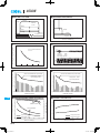
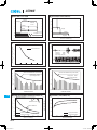
Basic Characteristics Data
Basic Characteristics Data
Model
Circuit method
Input module of
ACE300F
Input module of
ACE450F
Input module of
ACE650F
Input module of
ACE900F
Output module
A-K
Output module
2A-2K
Output module
L,M,N,P,R
Output module
Y,W,Z,9,Q,V
Output module
S,T,U
Active filter
*1
*2
*3
*4
*5
*6
*7
Switching frequency Input current
[kHz]
[A]
80
Rated input
fuse
Series/Parallel
PCB/Pattern
Inrush current
operation availability
protection
Material Single sided Double sided Series operation Parallel operation
3.7*1
250V 8A
SCR
FR-4
Yes
No
No
Active filter
80
5.7*2
250V 10A
SCR
FR-4
Yes
No
No
Active filter
80
8.0*3
250V 15A
SCR
FR-4
Yes
No
No
Active filter
80
11*4
250V 20A
SCR
FR-4
Yes
No
No
Forward converter
120
-
-
-
FR-4
Yes
Yes*5 Yes*7
Forward converter
120
-
-
-
FR-4
Yes
Yes*5 Yes*7
Forward converter
120
-
-
-
FR-4
Yes
Yes*5
No
Forward converter
120
-
-
-
FR-4
Yes
Yes*6
No
Forward converter
120
-
-
-
FR-4
Yes
Yes*6
No
Input current is based on Model AC3-HEEC-00 outputs 250W at AC100V.
Input current is based on Model AC4-HHECC-00 outputs 400W at AC100V.
Input current is based on Model AC6-HHECC-00 outputs 600W at AC100V.
Input current is based on Model AC9-HHEECC-00 outputs 800W at AC100V.
Series operation is possible with the same output modules.
Series operation is possible, but series bar cannot be set by the series code.
Parallel operation is possible with the same output voltage module.
ACE
ACE
ACE-8
ACE_E.indd 8
15.6.18 4:54:38 PM
ACE300F
OVER CURRENT CHARACTERISTICS
RISE TIME & FALL TIME
25.0
+24V(H)
+24V(H)
DC Output
20.0
OUTPUT VOLTAGE [V]
ACIN 100V
IO = 100%
+12V(E)
+5V(C)
+3.3V(B)
AC Input
15.0
10.0
+12V(E)
+5V(C)
5.0
+3.3V(B)
100ms/DIV
0
10ms/DIV
10
20
30
40
OUTPUT CURRENT [A]
INRUSH CURRENT (AC3-HEEC-00)
10A/DIV
INSTANTANEOUS COMPENSATION [ms]
INSTANTANEOUS INTERRUPTION COMPENSATION (AC3-HEEC-00)
INPUT VOLTAGE 100V
75
Frequency
60Hz
Load factor
100%
Input voltage AC100V
50
ACE
25
0
100
200
50ms/DIV
300
OUTPUT POWER [W]
INPUT HARMONIC CURRENT AC100V (AC3-HEEC-00)
INPUT HARMONIC CURRENT AC230V (AC3-HEEC-00)
10
Harmonic current standard class A (at odd number)
HARMONIC CURRENT [A]
HARMONIC CURRENT [A]
10
Output power 250W
Input voltage AC100V
1
0.1
0.01
0.001
Harmonic current standard class A (at odd number)
1
Output power 300W
Input voltage AC230V
0.1
0.01
0.001
0
10
20
30
40
0
10
HARMONIC ORDER
20
30
40
HARMONIC ORDER
EFFICIENCY (AC3-HEEC-00)
POWER FACTOR & INPUT CURRENT (AC3-HEEC-00)
1.0
ACE
85.0
8
6
5
0.8
INPUT CURRENT
4
0.7
Output power 250W
Output power 125W
3
2
0.6
80.0
EFFICIENCY [%]
POWER FACTOR
POWER FACTOR
INPUT CURRENT [A]
7
0.9
75.0
70.0
65.0
Output power 250W
Output power 125W
1
0.5
60
100
140
180
220
INPUT VOLTAGE [V]
260
0
300
60.0
60
100
140
180
220
260
300
INPUT VOLTAGE [V]
ACE-9
ACE-9
ACE_E.indd 9
15.6.18 4:54:38 PM
ACE450F
OVER CURRENT CHARACTERISTICS
RISE TIME & FALL TIME
25.0
+24V(H)
+24V(H)
20.0
DC Output
OUTPUT VOLTAGE [V]
ACIN 100V
IO = 100%
+12V(E)
+5V(C)
+3.3V(B)
AC Input
15.0
10.0
+12V(E)
+5V(C)
5.0
+3.3V(B)
100ms/DIV
0
10ms/DIV
10
20
30
40
OUTPUT CURRENT [A]
INRUSH CURRENT (AC4-HHECC-00)
ACE
10A/DIV
INSTANTANEOUS COMPENSATION [ms]
INSTANTANEOUS INTERRUPTION COMPENSATION (AC4-HHECC-00)
INPUT VOLTAGE 100V
75
Frequency
60Hz
Load factor
100%
Input voltage AC100V
50
25
0
100
200
300
50ms/DIV
400
OUTPUT POWER [W]
INPUT HARMONIC CURRENT AC100V (AC4-HHECC-00)
INPUT HARMONIC CURRENT AC230V (AC4-HHECC-00)
10
Harmonic current standard class A (at odd number)
HARMONIC CURRENT [A]
HARMONIC CURRENT [A]
10
Output power 400W
Input voltage AC100V
1
0.1
0.01
0.001
Harmonic current standard class A (at odd number)
1
Output power 450W
Input voltage AC230V
0.1
0.01
0.001
0
10
20
30
40
0
10
HARMONIC ORDER
ACE
20
30
40
HARMONIC ORDER
EFFICIENCY (AC4-HHECC-00)
POWER FACTOR & INPUT CURRENT (AC4-HHECC-00)
1.0
85.0
8
7
6
5
0.8
INPUT CURRENT
4
0.7
3
2
0.6
75.0
70.0
65.0
Output power 400W
Output power 200W
0.5
60
80.0
EFFICIENCY [%]
POWER FACTOR
INPUT CURRENT [A]
POWER FACTOR
0.9
100
140
180
Output power 400W
Output power 200W
1
220
INPUT VOLTAGE [V]
260
0
300
60.0
60
100
140
180
220
260
300
INPUT VOLTAGE [V]
ACE-10
ACE_E.indd 10
15.6.18 4:54:39 PM
ACE650F
OVER CURRENT CHARACTERISTICS
RISE TIME & FALL TIME
25.0
+24V(H)
+24V(H)
20.0
DC Output
OUTPUT VOLTAGE [V]
ACIN 100V
IO = 100%
+12V(E)
+5V(C)
+3.3V(B)
AC Input
15.0
10.0
+12V(E)
+5V(C)
5.0
+3.3V(B)
100ms/DIV
0
10ms/DIV
10
20
30
40
OUTPUT CURRENT [A]
INRUSH CURRENT (AC6-HHECC-00)
20A/DIV
INSTANTANEOUS COMPENSATION [ms]
INSTANTANEOUS INTERRUPTION COMPENSATION (AC6-HHECC-00)
INPUT VOLTAGE 100V
75
Frequency
60Hz
Load factor
100%
Input voltage AC100V
50
ACE
25
0
200
400
600
50ms/DIV
800
OUTPUT POWER [W]
INPUT HARMONIC CURRENT AC100V (AC6-HHECC-00)
INPUT HARMONIC CURRENT AC230V (AC6-HHECC-00)
10
Harmonic current standard class A (at odd number)
HARMONIC CURRENT [A]
HARMONIC CURRENT [A]
10
Output power 600W
Input voltage AC100V
1
0.1
0.01
0.001
Harmonic current standard class A (at odd number)
1
Output power 650W
Input voltage AC230V
0.1
0.01
0.001
0
10
20
30
40
0
10
HARMONIC ORDER
POWER FACTOR & INPUT CURRENT (AC6-HHECC-00)
1.0
30
40
EFFICIENCY (AC6-HHECC-00)
82.0
0.8
INPUT CURRENT
6
0.7
4
EFFICIENCY [%]
8
INPUT CURRENT [A]
10
POWER FACTOR
ACE
84.0
12
0.9
POWER FACTOR
20
HARMONIC ORDER
80.0
78.0
76.0
74.0
0.6
2
Output power 600W
Output power 300W
0.5
60
100
140
180
220
INPUT VOLTAGE [V]
260
0
300
Output power 600W
Output power 300W
72.0
70.0
60
100
140
180
220
260
300
INPUT VOLTAGE [V]
ACE-11
ACE-11
ACE_E.indd 11
15.6.18 4:54:39 PM
ACE900F
OVER CURRENT CHARACTERISTICS
RISE TIME & FALL TIME
25.0
+24V(H)
+24V(H)
DC Output
20.0
OUTPUT VOLTAGE [V]
ACIN 100V
IO = 100%
+12V(E)
+5V(C)
+3.3V(B)
AC Input
15.0
10.0
+12V(E)
+5V(C)
5.0
+3.3V(B)
100ms/DIV
0
10ms/DIV
10
20
30
40
OUTPUT CURRENT [A]
INRUSH CURRENT (AC9-HHEECC-00)
ACE
20A/DIV
INSTANTANEOUS COMPENSATION [ms]
INSTANTANEOUS INTERRUPTION COMPENSATION (AC9-HHEECC-00)
INPUT VOLTAGE 100V
75
Frequency
60Hz
Load factor
100%
Input voltage AC100V
50
25
0
250
500
750
50ms/DIV
1000
OUTPUT POWER [W]
INPUT HARMONIC CURRENT AC100V (AC9-HHEECC-00)
INPUT HARMONIC CURRENT AC230V (AC9-HHEECC-00)
10
Harmonic current standard class A (at odd number)
HARMONIC CURRENT [A]
HARMONIC CURRENT [A]
10
Output power 800W
Input voltage AC100V
1
0.1
0.01
0.001
Harmonic current standard class A (at odd number)
1
Output power 900W
Input voltage AC230V
0.1
0.01
0.001
0
10
20
30
40
0
10
HARMONIC ORDER
ACE
20
30
40
HARMONIC ORDER
EFFICIENCY (AC9-HHEECC-00)
POWER FACTOR & INPUT CURRENT (AC9-HHEECC-00)
1.0
85.0
16
12
10
0.8
INPUT CURRENT
8
0.7
6
4
0.6
75.0
70.0
65.0
Output power 800W
Output power 400W
0.5
60
80.0
EFFICIENCY [%]
POWER FACTOR
POWER FACTOR
INPUT CURRENT [A]
14
0.9
100
140
180
Output power 800W
Output power 400W
2
220
INPUT VOLTAGE [V]
260
0
300
60.0
60
100
140
180
220
260
300
INPUT VOLTAGE [V]
ACE-12
ACE_E.indd 12
15.6.18 4:54:39 PM
AC-DC Power Supplies Configurable Type Instruction Manual
1
Ordering information
ACE-14
2
Series operation and Parallel operation
in Modular power supply
ACE-15
3
2.1
Series operation
ACE-15
2.2
Parallel operation
ACE-15
Function
3.1
Input voltage range
ACE-15
3.2
Inrush current limiting
ACE-15
3.3
Overcurrent protection
ACE-16
3.4
Thermal protection
ACE-16
3.5
Overvoltage protection
ACE-16
3.6
Output voltage adjustment
ACE-16
3.7
Remote sensing
ACE-16
3.8
Remote ON/OFF
ACE-17
3.9
Isolation
ACE-17
3.10 Alarm
4
5
ACE-15
Assembling and installation method
ACE-17
ACE-18
4.1
Installation method
ACE-18
4.2
Derating
ACE-18
Option
ACE-21
Option outline
ACE-21
6
Input module
ACE-23
7
Medical electrical equipment
ACE-23
5.1
ACE
ACE
7.1
Type
ACE-23
7.2
Specification
ACE-23
7.3
Others
ACE-23
ACE-13
AC-DC Power Supplies Configurable Type
1 Ordering information
6
5
4
slot
Instruction Manual
lPART NUMBERING EXAMPLE (1)
AC9 OHHECC 01 08GW
Refer to options G W
3
2
1
code
H-module available in serial connection
at 24V 6.5(8)A, or 48V 6.5(8)A
C-module available in parallel
connection at 5V 46.8A
E-module 12V 13(14)A
code
AC
ACE300F
3:ACE300F
ACE450/650F
4:ACE450F
ACE900F
6:ACE650F
9:ACE900F Start from Slot1
Parallel code
Option
Series code
(”00” if parallel operation (Blank if not required)
is not required.)
Blank panel
Unit ACE900F
(Lower voltage to higher voltage.
If a module is not required, set ”0” for the slot.)
Choose from
Table1.1.
Series bar
Shorted bar
lPART NUMBERING EXAMPLE (2)
If the parallel operating module C (5V, 46.8A) in example (1) is
changed to module 2C(5V, 60A), the part number would change
to AC9-0HHE2C-00-08GW.
Refer to instruction
manual 5.
6
5
4
3
slot
2
lPART NUMBERING EXAMPLE (3)
1
Parallel and series operation of 2A-2K both use codes as in
Table 1.1.
For example, if connecting two modules 2E [12V, 25(34)A] in
Table 1.1 Parallel / Series code
code
ACE
slot6
slot5
slot4
slot3
slot2
slot1
series, and using these as 24V, 25(34)A, the part number would
change to AC9-002E2E-00-02.
00
01
ACE300F
02
lNaming rules
03
(1) Confirm the output voltage and current, and select the code for
04
05
output modules to be installed in slots 1-6 from the output mod-
06
ule specifications. Use an ”O” to designate slots where no out-
07
put module will be installed.
08
(2) If the supply will be operated in parallel or in series, refer to
ACE450/650F
09
Table 1.1 for the proper placement of the bus bar(s) between
0A
the output modules, and the appropriate code designation(s).
0B
0C
Refer to section 2 for notes on settings for series and parallel
0D
operation.
0E
(3) A minimum of two slots must be filled.
0F
(4) List of modules which may be used for series or parallel opera-
10
tion.
11
Parallel
setting
12
13
Series
setting
14
ACE
15
ACE900F
16
A-K, 2A-2K
L, M, N, P, R, S, T, U, Y, W, Z, 9, Q, V
A-K, 2A-2K, L, M, N, P, R
S, T, U, Y, W, Z, 9, Q, V
17
nSeries operation can provide a higher maximum output voltage,
18
depending on the modules used. In addition, series operation pro-
19
vides a dynamic load response superior to that of parallel opera-
1A
tion during abrupt changes in load. Therefore, we recommend op-
1B
eration in series for dynamic loads in order to increase power.
1C
1D
1E
1F
: Output terminal
: Connection
ACE-14
possible
impossible
possible
impossible
AC-DC Power Supplies Configurable Type
2 Series operation and
Parallel operation in
Modular power supply
Instruction Manual
Peak loads cannot be obtained.
In case that output voltage adjustment is required for modules
connected in parallel, the modules aforementioned must be adjusted. If precision adjustment is required, remove the bus bar
between modules, adjust the output voltage, and reinstall the
bus bar. The output voltage difference will appear as load regulation. To reduce the regulation, adjust the output voltage as
same as possible. Adjust the output voltage so that each volt-
2.1 Series operation
nSeries operation is possible only between identical output modules. If series operation is specified in the part number, the supply
will be shipped with a series bar installed. However, series operation is possible with modules S, T, U, Y, W, Z, 9, Q, and V, but series bar cannot be specified.
nThe output current in series operation is the same as that of the
individual modules that are connected.
nPlease consider the following items when configuring your supply
age get same value to reduce the regulation.
In case that output current changes rapidly such as pulse load,
the output voltage fluctuation (dynamic load regulation) value
may increase. Therefore, please consult us in advance if the
unit will be used for such a application.
nAt startup, modules connected in series or in parallel, may show
stepped input and output voltage waveforms. This is due to a delay in the rise time.
for series operation:
Input ON
Connect only the same type of modules in series.
AC Input voltage
A total rated voltage of up to 48V can be set up for series operation.
Modules in the same power supply can be set up for series or
parallel operation, but not both.
Please consult with us for usage other than in accordance with
ACE
Output voltage
Fig. 2.1 Start-up waveform for series and parallel operation
the above conditions.
3 Function
2.2 Parallel operation
(applying module : A-K, 2A-2K)
nParallel operation is possible using modules with identical output
voltage. If parallel operation is specified in the part number, the
supply will be internally configured accordingly, and shipped with
the appropriate bus bar in place. Parallel operation cannot be set
up once the unit has been shipped.
nOutput current in parallel operation.
3.1 Input voltage range
nThe input voltage range is from 85 VAC to 264 VAC, or 120 VDC to
350 VDC.
nIn cases that conform with safety standard, input voltage range is
AC100-AC240V(50/60Hz).
nBe aware that use of voltages other than those listed above may re-
Current ratings for output modules connected in parallel are
sult in the unit not operating according to specifications, or may
derated by 10%.
cause damage. Avoid square waveform input voltage, commonly
used in UPS units and inverters.
Ex.: AC4-HHECB-08
Parallel code 08 means slots 4 and 5 are connected in parallel.
current is as shown below:
Current = (6.5A+6.5A)
0.9=11.7 A
nPlease consider the following when configuring your supply for
parallel operation.
Please consult us as regarding usage methods for remote sensing.
ACE
3.2 Inrush current limiting
The output module for slots 4 and 5 is ”H”. Therefore, the
nInrush current limiting is built-in.
nIf a switch is being used for input, ensure that it is rated to handle
the input inrush current. When turning the power OFF and then
ON again within a short period of time, the inrush current limiting
may be disabled, therefore, ensure sufficient time elapses before
restarting.
nInrush current limiting uses a thyristor, therefore primary inrush
current and secondary inrush current are generated. If power is
turned ON and OFF repeatedly, failure may result. Please allow
enough time between power ON and OFF.
ACE-15
AC-DC Power Supplies Configurable Type
Instruction Manual
3.3 Overcurrent protection
3.6 Output voltage adjustment
nOvercurrent protection is built in (activated at 105% of the rated
nOutput voltage can be adjusted by turning the internal potentiom-
current, or for operation with peak current, at 101% of the peak
current); however avoid short circuits or overcurrent.The unit automatically recovers when the cause of the short or overcurrent is
cleared.
eter.
nRefer to specifications for adjustment ranges. Please consult with
us regarding operation outside the specified ranges.
For modules Y, W, Z, 9, and Q, turning the internal potentiome-
nWhen the output voltage drops as a result of the overcurrent circuit being activated, the average output current is reduced by in-
ter clockwise increases the positive voltage and decreases the
negative voltage simultaneously.
termittent operation of the power supply (intermittent overcurrent
mode).
nAuxiliary power (AUX)
Output that supplies power to the RC terminal of output modules.
AUX power is designed to be used for control of the remote
ON/OFF function.
nPeak current protection (applicable modules: 2E-2K)
Peak current protection is built in (refer to Output module specifications
1 for peak current usage methods).
Peak current protection operates independently for each output
3.7 Remote sensing
(applying module : A-K, 2A-2K)
nEach output module incorporates remote sensing functions.
nIf remote sensing is not used, then please short +S and +M,
and -S and -M at the CN2 output module.
Fig. 3.1 shows wiring for when remote sensing is not used.
The unit is shipped with harnesses for when remote sensing is
not used.
Output module
module. Its activation will not halt the entire power supply. Shut
ACE
off input AC voltage, wait for at least 2-3 minutes, and recycle to
OUT
+V
-V
CN2
+M
+S
-S
-M
recover output voltage( ).
The recovery time varies depending on input voltages and load
status during operation.
the thermal protection may be activated, shutting off the output:
The current or temperature is continuously in excess of the derating curve.
The fan has stopped or the airflow from the fan is reduced by an
obstruction.
If the thermal protection is activated, shut off input voltage, remove the cause of the overheating, wait for the unit to cool down,
and recycle to recover output voltage.
Short at connector
Fig. 3.1 When the remote sensing function is not used
3.4 Thermal protection
nThermal protection is built in. If either of the following takes place,
Load
nWiring method with remote sensing is shown in Fig.3.2.
nPlease consider the following when using remote sensing:
Be sure connections are made properly. If the load wire is not
connected correctly, a load current may flow through the sensing wire, which could damage circuitry inside the power supply.
Wire of an appropriate type and gauge should be used to connect the power supply to the load. Line drop should be less than
0.3V.
When using the remote sensing function, oscillation in the
power supply output voltage, or significant variations in output
3.5 Overvoltage protection
nOvervoltage protection operates independently for each output
ACE
voltages can be generated by wiring or load impedance.
The following are ways to remedy instability in output voltage.
module. Its activation will not halt the entire power supply.
Remove remote sensing from the negative side, and short -S
Overvoltage protection is built in. When the overvoltage protec-
and -M at the CN2 on each output module.
tion is activated, shut off input, wait for at least 1-2 minutes, and
recycle to recover output voltage.
The recovery time varies depending on input voltage, etc.
When testing the power supply for overvoltage performance or
applying voltage from the load circuit, please note that components inside the power supply might fail if the voltage applied exceeds the rated output voltage.
ACE-16
If oscillation occurs, connect C0, C1, and R1.
Please consult us for details.
nEnsure that current is not drawn from the CN2 +M or -M terminals.
AC-DC Power Supplies Configurable Type
OUT
+V
-V
Output module
C0
Table 3.1 Remote ON/OFF specifications
Connection method
Load
R1
SW
Logic
+M
CN2 +S
-S
-M
C1
Instruction Manual
Wire +S and -S as close as possible
Fig 3.3 Remote SW
SW open
(0-0.5V between RC+ and RC-)
Turn
on
SW close
(12V between RC+ and RC-)
CN2 RC-
Turn
off
Bases terminal
Fig. 3.2 When the remote sensing function is used
3.9 Isolation
3.8 Remote ON/OFF
nWhen performing incoming inspections, ensure that the applied volt-
nEach output module incorporates remote ON/OFF functions.
age is increased gradually. Additionally, when turning off power to
Output voltage ON/OFF can be controlled by applying a voltage
the unit, use a dial to gradually reduce the voltage. Do not use a
to CN2 at each output module.
voltage tester in conjunction with a timer. Doing so may generate
nDedicated auxiliary power (AUX) for remote ON/OFF.
voltage several times higher than the applied voltage.
Auxiliary power (AUX) is built-in for control of remote ON/OFF.
Auxiliary power (AUX) is isolated from input, output, and FG.
3.10 Alarm
Remote ON/OFF connection methods with AUX are shown in Fig.
nThe following two types of alarm function are built in.
3.3.
Refer to Table 3.2 for details.
nRemote ON/OFF control logic.
PR: abnormal input voltage, fan alarm
The output stops when voltage (4.5 - 12.5V) is applied to RC+.
LV : abnormal output module voltage (except modules S, T, and U).
Reverse logic option (-R) also available.Refer to section 5.
Option.
ACE
Table 3.2 Explanation of alarms
The built-in fan does not stop even if the output is turned OFF
Alarm
using remote ON/OFF.
If the output has been turned OFF using remote ON/OFF, the
PR
LV alarm signal will be generated (except modules, S, T, and
Output of alarm
Open collector method
Good : Low
(0-0.8V, 1-20mA)
Fail :35V max
When input voltage is abnormal (low
input voltage) or the fan stops, the
alarm signal is generated from CN1.
U).
This function operates on each output module independently.
nRemote ON/OFF circuits operate independently on each output
module; therefore it is possible to use remote ON/OFF on individual
output modules. Please be aware that this cannot turn off all
outputs together. If turning off all output modules together is a
requirement, we recommend use of the remote ON/OFF circuits in
series or parallel.
nThe remote ON/OFF circuit (RC+, RC-) is isolated from input, output, and FG.
SW
LV
When rated output voltage decreases
or stops, the alarm signal is generated from CN2.
Note : In the event of overcurrent
output (intermittent
current), operation of the
alarm will become
inconsistent.
The LV alarm is not
isolated from output.
Therefore, make sure all
connections are correct
when the power supply is
used to supply negative
voltage or is operated in
series. (Refer to Fig. 3.5).
Open collector method
Good : Low
(0-0.8V, 1-20mA)
Fail :35V max
Please consult us details.
Output module
AUX
Ri=
780
Turn
off
RC+
Turn
on
ACE
AUX
PR
RCCN1
G
CN2
G
Fig. 3.3 Example of use with remote ON/OFF
Fig. 3.4 PR internal circuit
ACE-17
Instruction Manual
AC-DC Power Supplies Configurable Type
+LV
+LV
+LV
-LV
-S
-LV
-V
-LV
COM
Applying module :
Applying module :
Applying module :
A-K, 2A-2K
L, M, N, P, R
Y, W, Z, 9, Q, V
Life expectancy of fan[H]
100,000
0V
AUX
12V
0
0
10 20
30
40
50
60
70
Ambient temperature [ ]
nWhen mounting the power supply with screws, it is recommended
Revolution
of FAN
that this be done as shown in Fig. 4.3. If other methods are used,
FAN trouble
be sure the weight of the power supply is taken into account.
H
L
H
L
Top
0V
H
LV alarm
10,000
Fig. 4.2 Life expectancy of fan(R(t)=90%)
Input
voltage
Remote
ON/OFF
Output
voltage
30,000
5,000
-10
Fig. 3.5 LV internal circuit
PR alarm
50,000
CN1 Top
Top
CN1
CN1
L
: unsetteled area
H : 2V H 35V or Open, L:L
ACE
A
0.8V
Fig. 3.6 Sequences for alarm types
C
B
Fig. 4.3 Installation method 1
nAvoid installation method 2 as shown in Fig. 4.4, which can cause
4 Assembling and
installation method
stress on the mounting holes.
nMaximum length of mounting screws is 6mm (Refer to Fig. 4.5).
Chassis of
customer system
4.1 Installation method
Chassis of
ACE series
nFans for forced air cooling are built in.
Ensure that the inlet (rear) and outlet (output terminal) vents are
not blocked, to prevent disruption of the airflow.
Option with reversed airflow (-F) is also available.
NO
FAN
Output
module
6mm max
CN1
Fig. 4.4 Installation method 2
Air flow
Screw M4
Fig. 4.5 Mounting screw
4.2 Derating
nThe ACE series comprises power supplies consisting of a combi-
ACE
Fig. 4.1 Air flow
nIf the unit is used in a dusty environment, an air filter should be
used so the cooling efficiency of the fan is not reduced.
nIf the fan stops, the thermal protection may be activated, shutting
down the output. Life expectancy of the fan varies depending on
usage conditions; therefore regular inspections of the fan are
required for increased reliability. Should the fan become nonoperational over the course of time, it can be replaced. Refer to
the optional parts section of this catalog.
ACE-18
nation of output modules. Make sure each output module is used
within specifications, and that the total output power of all modules is equal to, or less than the rated total output power.
nThe derating curve for the ambient temperature (inlet temperature
for cooling) of output modules is shown in Fig. 4.6.
nOperation within the hatched area will result in different ripple and
ripple noise specifications.
Instruction Manual
AC-DC Power Supplies Configurable Type
Peak total output power
1000
80
Total output power [W]
Load of output module [%]
1100
100
60
40
20
0
-20 -10
0
10
20
30
40
50
60
70
900
Total output power
800
720
700
600
Ambient temperature [ ]
85
90
Fig. 4.6 Derating curve for ambient temperature
264
nThe ACE900F can output peak power under the following conditions.
Output power [W]
350
Total output power [W]
170
Fig. 4.10 Derating curve for input voltage (ACE900F)
nThe derating curve with respect to input voltage is shown in Figs.
4.7 to 4.10.
150
Input voltage [VAC]
300
250
225
200
Pp
Pave : average power
P0
0
150
85
90
150
170
: peak total
output power
ACE
t [sec]
t2
t1
264
Input voltage [VAC]
t1
1 [sec], Pave =
Fig. 4.7 Derating curve for input voltage (ACE300F)
Pp t1 + P0 t2
t1 + t2
total output power,
t1
t1 + t2
0.3
Fig. 4.11 Peak output power (ACE900F only)
Total output power [W]
500
nDefinition of load factor
450
(Sum of each module power)
A0=
400
6
360
350
=
100
(Total output power)
k=1
(Ik1
Vk1 + Ik2
Vk2)
(Total output power)
100
Note : Only the number with a small occupation slot number is
300
85
90
150
170
264
Input voltage [VAC]
Fig. 4.8 Derating curve for input voltage (ACE450F)
calculated in 2A-2K.
A11, A21, A31, A41, A51, A61 : Ak1=Ik1 / I0k1
100
A12, A22, A32, A42, A52, A62 : Ak2=Ik2 / I0k2
100
Ik1 , Vk1 , I0k1: output current ( 1), voltage, and rated current
Total output power [W]
700
( 2) for modules S, T, and U (excepting V2).
Ik2 , Vk2, I0k2 : output current, voltage, and rated current for V2 in
650
modules S, T, and U.
Total output power: Dependent upon input voltage
600
(Refer to Figs.4.7-4.10)
550
540
1 The output current for module codes Y, W, Z, 9, Q, and V is
the sum of + and - output currents.
500
85
90
150
170
264
Input voltage [VAC]
Fig. 4.9 Derating curve for input voltage (ACE650F)
2 Rated output for modules is as below.
Excepting module codes Y, W, Z, 9, Q, and V
: Refer to output module specifications
Module codes Y, W, Z, 9, Q, and V
: 10A(Y), 6.4A(W) , 5A(Z), 3.2A(9)
12.8A(Q), 11A(V)
ACE-19
ACE
Instruction Manual
AC-DC Power Supplies Configurable Type
[%]
(Sum of +current and -current)
Load [%]=maximum value of A0 to A62
nLoad regulation in modules Y, W, Z, 9, Q, and V
Ensure that the sum of + and - output is less than total output as
follows: Y: 50W, W: 76.8W, Z: 75W, 9: 76.8W, Q: 153.6W, and V:
Load of V2
100
50
165W.
0
The relationship between current and load regulation is shown in
0.5
the following example(Refer to Fig. 4.12).
8
9
[A]
Output current of V1
Fig. 4.13 Minimum output current of V1
<Example for module W>
(1) Rated current 1 : 3.2A
1
When drawing current within the
range of +3.2A and -3.2A (total
6.4A), the specifications of load
nUsage example
regulation are as in ”Load
[Example1] Method to confirm that AC4-LWHEC-00 can be used
under the following conditions.
regulation 1”.
(2) Rated current 2 : 4.2A
ACE
(3) Peak current
: 5A
When drawing current within the
range +4.2A and -2.2A (or +2.2A
Input voltage : 100 VAC
and -4.2A, total 6.4A) the
Ambient temperature : 50
specifications of load regulation
Ouput module : slot1 :
5V 15A
are as in ”Load regulation 2”.
slot2 : 12V
7A
Loads of +5 A and -1.4 A (or +1.4
slot3 : 24V
6A
A and -5A, total 6.4A) are
slot4 : +12V
4A, -12V 1A
possible. However, refer to
slot5 : 3.3V 10A
Output Module Specifications
1
Calculating A11-A51
(Sum of each module power)
A0=
(Total output power)
when drawing 4.2-5A.
Load regulation
6
=
Load regulation2
Load regulation1
k=1
(Ik1
Vk1 + Ik2
100
Vk2)
(Total output power)
100
=396/400 100=99%
A11=I11/I011 100=15/26 100=58%
Peak current
Rated current 2
Rated current 1
Current
Range of using
ACE
A21=I21/I021 100=7/13 100=54%
A31=I31/I031 100=6/6.5 100=92%
A41=I41/I041 100=5/6.4 100=78%
A51=I51/I051 100=10/10 100=100%
Accordingly, because the derating curve (Fig. 4.6) indicates that up
to 100% of the maximum load can be used up to 50
and the
Fig. 4.12 The relationship between rated current and load regulation
largest value amongst A0, A11, A21, A31, A41, and A51 is 100%, this
nMinimum output current of modules S, T, and U.
assures that these input and output conditions are acceptable.
The allowable load of V2 dependent upon the output current of
V1 changes as follows.
ACE-20
AC-DC Power Supplies Configurable Type
Instruction Manual
Table 5.1 Reduced leakage current
[Example2] Method to confirm that AC9-2HCSWP-00 can be used
-E
-G
0.5mA max
0.15mA max
Class A
Not available
1.5 times standard 2.0 times standard
under the following conditions.
Leakage current (230 VAC)
Conducted Noise
Ripple Noise
Input voltage : 100 VAC
Ambient temperature : 50
Ouput module : slot1 : 15V
l-F
3A
slot2 : +12V 3.2A, -12V 2.3A
Specification with reversed air exhaust
slot3 :
5V
Differences from standard products are shown in Fig.5.1 and
slot4 :
5V 25A
8A,
5V
4A
Fig.5.2.
Please contact us for details about life expectancy of fan.
slot5 : 24V 13A
Air flow
=
(Ik1
k=1
Vk1 + Ik2
Vk2)
(Total output power)
100
Fig. 5.1 Air flow(-F)
100
Load of output module [%]
6
Output
module
FAN
Calculating A11-A51
(Sum of each module power)
A0=
(Total output power)
=608/800 100=76%
A11=I11/I011 100=3/4 100=75%
A21=I21/I021 100=5.5/6.4 100=86%
A31=I31/I031 100=8/10 100=80%
A32=I32/I032 100=4/5 100=80%
A41=I41/I041 100=25/26 100=96%
A51=I51/I051 100=13/14 100=93%
80
60
40
ACE
20
0
-20 -10
0
10
20
30
40
50
60
70
Ambient temperature [ ](-F)
Accordingly, because the derating curve (Fig. 4.6) indicates that up
to 100% of the maximum load can be used up to 50
100
Fig. 5.2 Derating curve characteristics resulting from ambient temperature (-F)
and the
largest value amongst A0, A11, A21, A31, A32, A41, and A51 is 96%,
The derating curve of output modules based on input voltage is
this assures that these input and output conditions are acceptable.
also different for the ACE900F.
l-N(External specifications may vary; please contact us for details)
5 Option
In the event that cooling can be provided by the user’s fan, the
built-in fan may be eliminated (Refer to Fig.5.3).
If applying for agency approval, it is necessary to measure the
5.1 Option outline
nPlease contact us in advance as regards detailed specifications
and delivery.
temperature of the transformer.
Please contact us for details on cooling methods.
Air
nPlease refer to ”1. Ordering information” for ordering methods.
nWhile some combinations of options are possible, others are not.
ACE
Please contact us for details.
l-E, -G
Reduced leakage current type.
Differences from standard products are shown Table 5.1.
Fig. 5.3 Dwg. of -N specification
ACE-21
AC-DC Power Supplies Configurable Type
Load of output module [%]
l-K
Specification with lower speed fan for reduced noise.
Load of output module [%]
The difference from standard is shown Fig.5.4.
100
80
60
100
80
60
40
20
40
0
10
20
30
40
50
60
70
Fig. 5.5 Derating curve for operational ambient temperature (-T)
0
10
20
30
40
50
60
70
Ambient temperature [ ]
Fig. 5.4 Derating curve based on ambient temperature (-K)
l-U
Specifications for support of instantaneous voltage dips (low
input voltage support).
Use condition
l-R
Specification with reversed logic for remote ON/OFF operation.
Input
module, it will not function as long as voltage is not applied to
the RC terminal.
Turn on : 12[V] between RC+ and RCTurn off : 0-0.5[V] between RC+ and RC-
70 VAC(100 VDC)
Duty 1s/30s
If -R is specified, then even if input voltage is applied to the
ACE
0
-20 -10
Ambient temperature [ ]
20
0
-20 -10
Instruction Manual
Output
ACE300F 200W
ACE450F 360W
ACE650F 540W
ACE900F 720W
Avoid continuous use for more than 1 second under the
-R specification applies to all installed output modules.
conditions mentioned above, as such use can lead to damage to
A harness is required for connecting to CN2 when using these
the power supply.
specifications.
Please use H-SN-16 to H-SN-18, etc.
When the customer is to provide a harness, please note the
Specification with terminal covers attached to output modules.
remote sensing wiring (refer to section 3.7, ”Remote Sensing”).
If -W is specified, a terminal cover is attached to all installed
Please consult us if specifications that mix normal logic and
output modules.
reverse logic are required.
l-T(External specifications may vary; please contact us for details)
Specification that adds a filter to prevent the entry of foreign
bodies.
The difference from standard products is shown in Fig.5.5.
Combinations with -F and -K are not possible.
Dust can result in clogging and reduced cooling; therefore it is
required that the unit is used in a dust-free environment, or that
ACE
l-W(External specifications may vary; please contact us for details)
it is periodically cleaned.
ACE-22
Instruction Manual
AC-DC Power Supplies Configurable Type
7.2 Specification
6 Input module
Safety : UL60601-1 (CSA601.1), EN60601-1
Isolation : 4,000 VAC input-output, RC, AUX 1min.
cutoff current 10mA
Input terminals for the ACE300F, 450F, and 650F are upon the fan
mount surface, however these can be situated on the output side.
leakage current : 0.3mA max (100 VAC), 0.5mA max (230 VAC)
0.1mA max. is also possible.
This places the input module (I) in the far left slot of each module,
instead of the output module.External dimensions will change.
conducted noise : complies with FCC-A, VCCI-A, CISPR22-A,
EN55022-A
Consult us for details.
Supported modules
ex : AC3 I CBA 00
All modules except S, T, and U modules with ”output module
Output module
Input module
specification.” Please note that there is no support for modules
S, T, and U.
Ripple noise
Ripple noise is 1.5 times that of standard models.
7.3 Others
If applying for medical equipment agency approval, use fuses or
L
N
FG
I
C
B
breakers that comply with applicable safety regulations on input
A
terminals.
L
With module I specified, conducted noise is class A.
ACE
L
N
N
or
7 Medical electrical equipment
FUSE ACE300F 250 VAC8A
ACE450F 250 VAC10A
ACE650F 250 VAC15A ACE900F 250 VAC20A
Specifications supporting medical electrical equipment.Types and
specifications, etc. are below. Please contact us for details.
L
N
7.1 Type
AC
Fig.7.1 Connecting FUSE
Fig. 7.2 Connecting circuit breaker
H
When units that support use as medical electrical equipment and
other options are combined, the end of the type name is as follows.
AC
H
,
:other options
Refer to instruction manual 5. for Option.
Example of use in conjunction with option -K model (reduced
fan speed).
AC
ACE
HK
Options that cannot be used in conjunction with this are as follows:
C : coating
E : low leakage current
Option -H is a low leakage current specification product.
Refer to section 7.2 for details.
ACE-23