1
User Manual
Eproms RKM - RKE
Microface E 24VAC
&
Hiromatic E
Code 272111 rev. 12.12.2005
INDEX
1
INTRODUCTION...................................................................................................................................................... 2
1.1
2
FOREWORD ......................................................................................................................................................... 2
HARDWARE ............................................................................................................................................................ 2
2.1
MICROFACE EVOLUTION 24V AC ...................................................................................................................... 2
2.2
LCD DISPLAY ..................................................................................................................................................... 3
2.3
EPROM ................................................................................................................................................................ 4
2.4
PTC TEMPERATURE SENSOR ............................................................................................................................ 4
2.5
HIROMATIC E ...................................................................................................................................................... 5
2.5.1
Hiromatic E direct Connection to Microface ......................................................................................... 5
2.5.2
Hiromatic E Backside View, Jumpers and Eprom Position................................................................ 6
2.6
POWER SUPPLY MODULE FOR HIROMATIC (24V ONLY) ................................................................................... 7
2.6.1
PSM Hardware ......................................................................................................................................... 7
2.6.2
PSM Connection (24V only) ................................................................................................................... 7
2.7
HIROBUS CABLES AND OTHER CONNECTION CABLES ....................................................................................... 8
2.8
HARDWARE, TECHNICAL SPECIFICATION........................................................................................................... 9
2.9
SPARE PARTS LIST ............................................................................................................................................. 9
3
SOFTWARE ........................................................................................................................................................... 10
3.1
THE LCD DISPLAY ........................................................................................................................................... 10
3.1.1
How to move through the Values/Parameters of the LCD Display................................................. 11
3.1.2
How to change Parameters .................................................................................................................. 11
3.1.3
How to reset Alarms or Warnings ........................................................................................................ 11
3.1.4
Tricks........................................................................................................................................................ 11
3.2
THE LCD PARAMETERS ................................................................................................................................... 12
3.2.1
The Warnings and Alarms table........................................................................................................... 13
3.3
HIROMATIC E .................................................................................................................................................... 14
3.3.1
Layout ...................................................................................................................................................... 14
3.3.2
Hiromatic E Windows ............................................................................................................................ 15
4
CONNECTION GUIDE.......................................................................................................................................... 16
1
1
1
Introduction
1.1
Foreword
This User Manual describes the Microface E Control System. It contains information concerning the
architectures of the control systems.
In the following sections first the Hardware, and later the Software (Firmware) are explained in detail.
In case of Remote control system only the SNMP is allowed from Microface E and, the related TRAPS
identification, are available on SNMP Control manual cod 272703 rev. 12.12.05 or higher
2
Hardware
2.1
Microface Evolution 24V AC
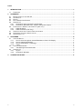
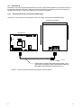
The Microface Evolution is a microprocessor-based electronic card, which is able to manage the devices and
the sensors installed in the unit
Microface E is installed in the electrical panel of indoor-units together with a User-interface module (“LCD
Display”), which allows to read/set/reset values, parameters and alarms.
To get access to the Microface E connections and Jumpers the LCD Display (if present) has to be removed
from its 4 mounting pins.
As the Microface E is the “Heart” of the System, which controls all Functions of the Unit, the Jumpers have to
be set in order to set-up the control board according to the requested functions; all jumpers are normally set
in the factory as described on the table below.
The meaning of Input and Outputs are available at Connection Guide chapter included inside this manual
4
Backup battery
6 7
5
F
3
EPROM
2
A
1
B
C
D
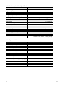
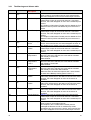
Figure 1 – Microface E 24V AC with connectors and jumpers.
Identification
1
2
3
4
5
6
7
A
B
C
D
F
2
Explanation
This Jumpers block is used to define the size of Eprom:
Up to 2Mbit =
Up to 4mbit =
(Factory Setting)
Sub Group Unit setting: not used, no jumpers set
External Access: Never remove this Jumper
Analog Input Jumper Block: Not Used
Microface ID Jumpers block: Never Set these jumpers (Hirobus Network not available)
EEprom Writing Enabled:
Enabled =
(Factory Setting; never remove the jumper)
Disabled =
Not Used
RS 485 connector for HiSNMP
Hirobus Slave 8 poles connector for Remote Display
Not Used
Hirobus Master 8 poles connector for Hiromatic E
I2C connector for Local Display
2
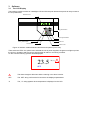
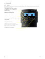
2.2
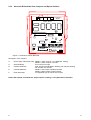
Backlit LCD
LCD Display
There are two different Displays available:
“Local” Display
“Remote” Display
23.0
Both Displays have the same Front-View:
Up-push-button
Down-push-button
Enter push-button
Red LED
Green LED
Yellow LED
Figure 2 – LCD Display Front View (with plastic cover)
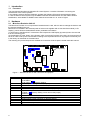
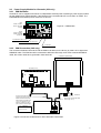
Just the backside connections are different, because of the different connection types to the Microface E:
Local or Remote Display.
"LOCAL" LCD DISPLAY
"REMOTE" LCD DISPLAY
Six poles connector for
the connection to the
external panel Switch
and LED
FERRITE
CONNECTION TYPE A:
4 wires flat cable
(410 mm max. length)
Alternative !!
MICROFACE E
CONNECTION TYPE B
(HIROBUS):
8 wires screened flat cable.
Screen connected on both
sides to earth.
MAX LENGTH: 20 m.
Figure 3 – Local and Remote Display Backside
Never use cables longer than 410 mm (Local Display) or longer than 20m (Remote Display)!
3
3
2.3
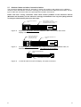
Eprom
The Eprom is the device, which stores the Program; the Microface has to work with. It doesn’t store any
user-settings; this is done by the Microface itself (in the RAM and the E2Prom). The Version Name and the
Number are printed on the Label of the Eprom.
The following Eproms are today in use for Standard Rack unit (the *.* is a placeholder for the actual
Version):
RKM-1.60*.*
RKE-1.60*.*
4 Mbit Flash for Microface E 24V Ac
4 Mbit Flash, for Hiromatic E.
Figure 4 - Eprom
Un-power the Microface before mounting/dismounting the Eprom. Remove Eprom only with special
tool; never use a screwdriver. For correct direction of mounting please refer to Figure 1 in Chapter
2.1 for Microface, and Figure 8 in Chapter 2.6.2 for Hiromatic E. Compare the Mark in the Eprom with
the direction in the Drawing.
2.4
PTC Temperature Sensor
The PTC Sensor is temperature-sensors, changing the resistance according to the temperature (positive
temperature coefficient). The connection is 2 poles. The length of the cable for the sensor ranges from 2 to
10 meters. It is used to monitor the inlet and outlet temperatures of the rack.
Measuring
Element
Cable
Figure 5 – PTC Sensor
4
4
2.5
Hiromatic E
Hiromatic E is a microprocessor-based electronic device, which makes possible to control the functions of
the Microface devices. Hiromatic E offers numerous advantages of programming the units as well as to
optimise their operation using various features, see chapter 3, Software.
2.5.1
Hiromatic E direct Connection to Microface
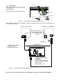
Hiromatic E can be fixed on the front panel of the unit, simply connecting the HIROBUS cable
HIROMATIC (BACKSIDE)
EPROM
MICROFACE E
FERRITE
Eight wires screened flat cable (max length: 10 m)
(Use direct connection when the distance between
Microface and Hiromatic is less than 10 m)
Figure 6 – direct Connection between Microface E and Hiromatic E
5
5
2.5.2
Hiromatic E Backside View, Jumpers and Eprom Position
Transformer
Board
Display Board
Backup Battery
C
E
A
EPROM
D
Hironet
Hirobus
F
Figure 7– Hiromatic Evolution Backside
Description of the Jumpers:
A:
C:
D:
E:
F:
Eprom (2M) / Flash Size (4M): Middle + Upper Jumper: 2 or 4 MBit (std. setting)
Middle + Lower Jumper: not used.
Write Disabling:
do not set this Jumper
Interface Selection:
both Jumpers as indicated in Drawing: RS 485 (std. setting)
No Jumpers set: RS 422
Contrast Selection:
Middle + Left Jumper: Variable Contrast
Middle + Right Jumper: Fixed Contrast
Flash download:
not supported yet. Do not set this Jumper
Please take special care about the Jumpers when installing a new (Spare Part) Hiromatic!
6
6
2.6 Power Supply Module for Hiromatic (24V only)
2.6.1 PSM Hardware
Hiromatic E can be supplied mounted in an independent electrical panel containing a power supply module
as well (PSM Power Supply Module), if the Distance to the next Microface E is more than 10 meters. The
PSM Module itself needs a power of 24V AC or 24V DC.
Input
24VAC / 24VDC+
24VAC / DC GND
not used
Figure 8 – PSM Module
Output
24VAC / 24VDC+
24VAC / DC GND
(max 6.5A)
Fuse 8x20mm, 250V, T1.6A
from Microface
to Hiromatic
2.6.2
PSM Connection (24V only)
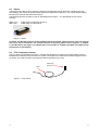
The connection between Hiromatic E and the PSM is carried out in the factory by means of an eight wires
HIROBUS cable. The PSM should be connected to Microface E through a six wires screened HIROBUS
cable; the screen needs to be grounded in both terminals.
HIROMATIC (BACKSIDE)
EPROM
MICROFACE E
FERRITE
Six wires screened flat cable.
(Use this connection when the
distance between Microface
and Hiromatic is greater than
10 m). The length may vary
within the total limit of 300 m
(max. Hirobus overall length).
Eight wires screened flat cable
(max length: 10 m)
Power Supply for
PSM:
24VAC; 24V DC
POW ER SUPPLY MODULE (PSM)
Figure 9 Connection of Microface E LAN to Hiromatic E with PSM.
7
7
2.7
Hirobus Cables and other Connection Cables
The connections between Microface E, Hiromatic E, display are carried out with cables having a different
number of wires and different connectors. Following you can find how these cables have to be done. For the
type of cable and connectors refer to the spare part list included in this manual.
Please note that a wrong connection could cause serious problems to the electronic devices
(Microface and Hiromatic); for this reason we strongly recommend to use only first quality products
or to buy the cables directly from your sales reps..
EIGHT POLES MODULAR
JACK
Figure 10
EIGHT WIRES FLAT CABLE.
USE SCREENED CABLE WHEN CABLE
IS RUNNING OUTSIDE THE UNIT.
Eight-wires; eight poles connector HIROBUS cable, for Hiromatic and remote
Display connections
EIGHT POLES MODULAR
JACK (USE ONLY THE
CENTRAL SIX POLES)
Figure 11
SIX WIRES SCREENED FLAT
CABLE
Six-wires eight poles connectors (Pin 1 and 8 not connected) HIROBUS cable, for
Microface E and PSM, connection. This cable must be screened.
FOUR POLES MODULAR
JACK
FOUR WIRES FLAT CABLE
Figure 12
8
4 wires flat cable for local LCD Display, four poles connectors.
8
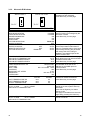
2.8
Hardware, Technical Specification
MICROFACE E 24V AC
Power Supply
Digital Out (Triac)
Digital Out (Relay)
Analogue Out (0-10V)
Analogue In (resistive)
Analogue In (resistive / 0-10VDC)
Storage Temperature
Operating Temperature Range
PTC Temperature sensor
24VAC, ± 10%; 50 Hz
7
2 (max. 24V – 1A)
2
8
3
-10 (not condensing) to +65°C
0 (not condensing) to +55°C
Cable length
Temperature range
Point of calibration
Hiromatic E
Power Supply
Graphic Display
Mounting hole
Power Supply Module (PSM)
Power supply
Output
2.9
1,5 m and 10m
-28 to 100°C
2000Ω at 25.0°C
10VDC (from Hirobus)
Backlit, 200 x 64 pixels
175 x 150mm
24VAC, ± 10%; 24VDC, ± 20%
10VDC (Hirobus, stabilised);
24VAC, ± 10%; 24VDC, ± 20% (filtered)
Spare Parts List
DESCRIPTION
Switch + Led
Microface E (Evolution) 24 AC board
Local LCD display for Microface
CODE
255039
275297
275098
Remote LCD display for Microface
Probe temperature PTC
Probe PTC 2 kohm L = 10 m
EPROM Microface E RKM-160*.*
EPROM Hiromatic E RKE-160*.*
Hiromatic Evolution
Flat cable 8 way M-M L = 1 m
Flat cable 8 way M-M L = 10 m
Flat cable 8 way screened (specify length)
Module PSM 24/24-10 for Hiromatic
Plastic holder for Microface only
Plastic holder for Microface and LCD display
Hirobus / Hironet Cable Tester
Hirobus / Hironet Interface Tester
275662
275183
275155
276226
276227
275691
275607
275610
275626
275316
270002
270003
480061
480060
9
9
3
3.1
Software
The LCD Display
The interface module consists of a backlight LCD and of three push buttons that permit an easy access to
the unit parameters.
Backlit LCD
23.0
Up-push-button
Down-push-button
Enter push-button
Red Led
Green Led
Yellow Led
Figure 13 Interface module between Microface and operator (front view).
There are three LED’s: the yellow Led to indicate the unit is power supplied, the green one lights up when
the unit is in operation and the red one signals either an alarm or a warning condition.
On the LCD the following symbols will be displayed:
23.5
°C(%)
!
SET
!
The alarm triangle is ON when either a warning or an alarm is active.
SET
The ‘SET’ string confirms the full access to the displayed parameters.
°C
The „°C“ string appears when temperature is displayed on the LCD.
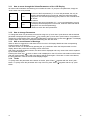
3.1.1
How to move through the Values/Parameters of the LCD Display
All Values and Parameters are listed up just one after the other. To jump the next parameter, simply the
“down” button has to be pressed.
$
65
$
65
3.1.2
The name of the first parameter ($ is not a real parameter, but only an
example) will be displayed for one second, while the value itself will be
displayed for two seconds (alternating) (this position is also considered as
the “Home”.
“Up” and “down” push-buttons
The name of the second parameter ($is not a real parameter, but only
an example) will be displayed for one second, while the value itself will be
displayed for two seconds (alternating).
“Up” and “down” push buttons to reach the other parameters.
How to change Parameters
To change the value of a parameter scroll the list using the “up” and “down” push-buttons until the desired
parameter is displayed and press “Enter” (↵). By pressing the “up” and “down” push buttons, it is possible to
change the corresponding value; after having obtained the required value, press enter (↵) again. The display
will show again the name of the parameter alternating with the new value.
3.1.3
How to reset Alarms or Warnings
When an alarm is triggered, the red alarm LED is lit on the LCD Display Module and the corresponding
symbol is shown in the Display.
The Alarm section can be reached by pressing the “up” push-button when the first parameter is on the
display; alarms are pointed out according to their code order.
After having entered the alarm section, the alarm code is displayed and every second the code is replaced
by the coded description.
Pressing the “Enter” key (↵), when an alarm code is displayed on the LCD, all the active alarms will be reset.
After the reset operation, all the still active alarms will be shown again. If there are no more active alarms,
the first parameter / value of the list will be displayed again.
3.1.4
Tricks
To quickly reach the parameter at the bottom of the list, press “Enter” (↵) together with the “down” pushbutton. To quickly reach the parameter at the top of the list, press “Enter” (↵) together with the “up” pushbutton.
11
11
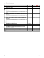
3.2
The LCD Parameters
LCD
Description
(# Inlet Temperature: this is the average of the 2 inlet sensors
temperature values.
(", Outlet Temperature: this is the actual outlet temperature value
(High Inlet Temperature Level 1: this parameter allows defining
at which inlet temperature value the related warning has to be
activated.
The event is not considered for a time of 5 minutes at each unit
ON
)High Inlet Temperature Level 2: this parameter allows defining
at which inlet temperature value the related warning has to be
activated.
The event is not considered for a time of 5 minutes at each unit
ON
)High Outlet Temperature: this parameter allows defining at
which outlet temperature value the related warning has to be
activated.
The event is not considered for a time of 5 minutes at each unit
ON
IP Address 1 for SNMP protocol
IP Address 2 for SNMP protocol
IP Address 3 for SNMP protocol
IP Address 4 for SNMP protocol
%Listen Port Address for SNMP protocol
'( Standard Settings: forcing to 2' all parameters will be set
according to the standard factory settings. The parameter
changes automatically to #" as soon as the value of one
parameter is modified
Calibration
of Inlet Temperature Sensor (SX)
Calibration
of Inlet Temperature Sensor (DX)
Calibration
of Outlet Temperature Sensor
12
Range
Res.
--
0.1 (°C)
-No, 1 – 99
0.1 (°C)
1 (°C)
No, 1 – 99
1 (°C)
No, 1 – 99
1 (°C)
0 – 255
0 – 255
0 – 255
0 – 255
0 – 2000
No, Yes
1
1
1
1
1
-
-9.9 - +9.9
-9.9 - +9.9
-9.9 - +9.9
0.1 (°C)
0.1 (°C)
0.1 (°C)
User
Value
---
12
3.2.1
The Warnings and Alarms table
Number
& Hiromatic E
description
Smoke Alarm
*"
Rear Door Open
"
Front Door Open
"
Backup Cooling
Active
Fire Detection
Failure
"(
High Outlet
Temperature
)
High Inlet
Temperature
Level 1
)
High Inlet
Temperature
Level 2
"&
Outlet Sensor
Failure
&
Inlet SX Sensor
Failure
&
Inlet DX Sensor
Failure
& Smoke Warning
*
Fire Alarm
13
LCD code
Type
Alarm: the event is activated if the unit is ON and the related
input is open for 5 seconds minimum: Auto-reset function;
the event disappear as soon as the related input is closed
Warning: the event is activated if the unit is ON and the
related input is open for 5 seconds minimum: Auto-reset
function; the event disappear as soon as the related input is
closed.
The Output 2 of Microface E board (used to disable the Fire
Detection Device) will be activated every time the event is
active.
Alarm: the event is activated when the backup cooling is
active: Auto-reset function; the event disappear as soon as
the related input is closed or the ( event is not present
Warning: the event is activated if the unit is ON and the
related input is open for 5 seconds minimum: Auto-reset
function; the event disappear as soon as the related input is
closed.
Warning: the event is ignored for 5 minutes at each Unit ON
then if the limit set is reached, the event will be activated
with a delay of 5 seconds:
Manual Reset
Warning: the event is ignored for 5 minutes at each Unit ON
then if the limit set is reached, the event will be activated
with a delay of 5 seconds:
Manual Reset
Alarm: the event is ignored for 5 minutes at each Unit ON
then if the limit set is reached, the event will be activated
with a delay of 5 seconds: Manual Reset
When the event is active the Output 0 and 7 are activated
as weel as the Backup Cooling (see " and *)
Warning: the event is activated with a delay of 30 seconds
without any influence from the status of the unit: Auto-reset
function; the event disappear as soon as the sensor is
available
Warning: the event is activated with a delay of 30 seconds
without any influence from the status of the unit: Auto-reset
function; the event disappear as soon as the sensor is
available
Warning: the event is activated with a delay of 30 seconds
without any influence from the status of the unit: Auto-reset
function; the event disappear as soon as the sensor is
available
Warning: the event is activated if the unit is ON and the
related input is open for 5 seconds minimum: Auto-reset
function; the event disappear as soon as the related input is
closed
Alarm: the event is activated if the unit is ON and the related
input is open for 5 seconds minimum
The Outputs 0 and 7 of Microface E board (used to
managed the Remote On Off of conditioners) will be
activated every time the event is active: Auto-reset function;
the event disappear as soon as the related input is closed
13
3.3
3.3.1
Hiromatic E
Layout
The front panel of Hiromatic E consists of a backlight graphic LCD, of eight push buttons that permit input
function and of two LED.
Cursor Buttons: to move inside the Menu;
Up and Down to go to the next or
previous window
Push-button to start/stop the unit
Help Key: not used
RACK INLET
23.5°C
RACK OUTLET
45.8°C
SYSTEM ON
This LED (orange) will be ON when the unit is
power supplied
Alarms and warnings reset.
GREEN when the Unit is in Operation,
YELLOW if the Units is in Warning condition,
RED if the Unit is in Alarm condition
ENTER Button, to set Parameters
14
14
3.3.2
Hiromatic E Windows
RACK INLET
20.0°C
On the main page the actual
temperatures are displayed.
Press Down key for next page
RACK OUTLET
35.0°C
STATUS OFF
INPUTS STATUS
REAR DOOR STATUS
FRONT DOOR STATUS
SMOKE WARNING OK
SKOKE ALARM
FIRE ALARM
EXT.FIRE DETECTION
BACKUP COOLING
OUTPUTS STATUS
BACKUP COOLING
REMOTE UNIT STATUS
EXT.FIRE DETECTION
CLOSED
CLOSED
OK
OK
OK
ENABLED
OFF
OFF
OFF
ENABLED
TEMPERATURE WARNINGS
HIGH OUTLET TEMPERATURE
HIGH INLET TEMPERATURE 1
HIGH INLET TEMPERATURE 2
HIROMATIC SETTINGS
PIEZO FEQUENCYOFF / 2.0
LANGUAGE
DATE / TIME
CONTRAST
BACKLIGHT OFF AFTER
ADDRESS IP
LISTEN PORT
SENSORS CALIBRATION
No°C
38°C
45°C
LISTEN PORT
ENGLISH
MO 21/11/2005 16:30
220
5 min
129.100.19.115
165
ACTUAL
00.0
00.0
00.0
INLET TEMPERATURE SX
INLET TEMPERATURE DX
OUTLET TEMPERATURE
STATUS REPORT PAGE 1
(01) 21.11.2005
16:30 RESET
HIGH OUTLET TEMPERATURE
STATUS REPORT PAGE 0
(01) 21.11.2005
16:30 RESET
HIGH OUTLET TEMPERATURE
15
AUTO
AUTO
AUTO
OFFSET
0.0
0.0
0.0
SYSTEM
UNIT
The inputs status page shows the
status of each input managed by the
Microface E board
Press Down key for next page
The outputs status page shows the
actual output status of Microface E
board. It is possible also to force each
output easily selecting the parameter
and change the AUTO string to
MANUAL; the related output in this
case is forced to ON
The parameters included on this page
allow defining the high inlet and outlet
temperature limit value
Press Down key for next page
On this page is possible to configure
the Hiromatic E as well as the
address for the SNMP protocol
communication.
Press Down key for next page
If required the offset of sensors
mounted on board can be done.
Press Down key for next page
On system status report page all
events (up to 200; system and unit)
are stored.
Press Left or Right key for Status
Report of Unit.
This page is reachable from the main
page easily pressing the Home key
On unit status report page; the last 3
events are stored
15
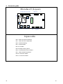
4
Connection guide
Gnd
An2
An1
An0
Pe
0
24
Ptc 7
Gnd
Ptc 6
Gnd
Ptc 5
Gnd
Ptc 4
Gnd
Ptc 3
Gnd
Ptc 2
Gnd
Ptc 1
Gnd
Ptc 0
Gnd
Out 6
Out 5
Out 4
Out 3
Out 2
Out 1
G
Microface E (Layuot)
Microfuse
Gnd
Local Display
connector
G0
G
Eprom
I-Module
Ac1
Ac2
Out 8
connectors
Nc-Out7
C-Out 7
No-Out7
Nc-Out8
C-Out8
No-Out8
Hirobus network
connector
G
AnOut 0
AnOut 1
G0
Humitemp, xTU’s
Inputs table
•Ptc 0 = Rack Sx Inlet Temperature
•Ptc 1 = Rack Dx Inlet Temperature
•Ptc 2 = Smoke Warning
•Ptc 3 = Smoke Alarm
•Ptc 4= Fire Alarm
•Ptc 5= Backup Cooling Active
•Ptc 6 = Fire Detection Device Faulire
•Ptc 7 = Rack Outlet Temperature
•Ana 0 = Rear Door Status
•Ana 1 = Front Door Status
16
16
Outputs table
•Out 1 = Fan & Damper
•Out 2 = Fire Detection device Enable / Disable
•Out 0 = Remote Unit On Off
•Out 7 = Remote Unit On Off
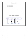
Power supply &Sensors
+24
0 PE
POWER
SUPPLY
17
PTC 0
GND
INLET SX PTC
SENSOR
PTC 1
GND
INLET DX PTC
SENSOR
PTC X
GND
OUTLET PTC
SENSOR
17
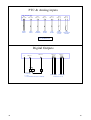
PTC & Analog inputs
No Jumper set
AN0
GND AN0
AN1
GND AN1
FRONT
DOOR
REAR
DOOR
PTC 2
GND P2
PTC 3
GND P3
SMOKE
WARNING
PTC 5
GND P5
PTC 4
GND P4
SMOKE
ALARM
FIRE
ALARM
PTC 6
GND P6
EMER.
COOLING
ACTIVE
FIRE
DETECTION
FAILURE
N.C = OK
N.O = ALARM ACTIVE
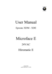
Digital Outputs
D
F
Nc
No
Co
Nc
DIG Out 7
V
D = Damper
F = Fan
V = Fire detection device (On = Disabled)
18
DIG Out 0
No
DIG Out 2
2
DIG Out 1
1
Co
G
(max.24VAC)
(max.24VAC)
Remote unit on / off
18