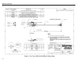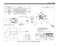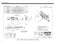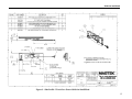
1
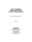
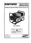
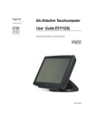
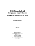
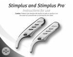
LOW POWER
SHIFT-OUT INTELLIHEAD
USER MANUAL
Specification Part Number 99875349-4
MARCH 2009
AN ISO 9001 REGISTERED COMPANY
1710 Apollo Court
Seal Beach, CA 90740
Phone: (562) 546-6400
Fax: (562) 546-6301
Technical Support: (651) 415-6800
www.magtek.com
Copyright© 2001-2009
MagTek®, Inc.
Printed in the United States of America
Information in this document is subject to change without notice. No part of this document may
be reproduced or transmitted in any form or by any means, electronic or mechanical, for any
purpose, without the express written permission of MagTek, Inc.
MagTek is a registered trademark of MagTek, Inc.
MLF is a trademark of Amkor, Inc.
REVISIONS
ii
Rev Number
1
2
3
Date
18 Jan 07
6 Jul 07
1 Oct 08
4
23 Mar 09
Notes
Initial Release
Added 21030036
Updated address; Updated drawings and added 21030041,
21044013, 21045092, 21047021
Changed low swipe speed spec from 3 to 6IPS, add 21030031,
Added Warranty and Agency Approval information.
LIMITED WARRANTY
MagTek warrants that the products sold pursuant to this Agreement will perform in accordance with MagTek’s
published specifications. This warranty shall be provided only for a period of one year from the date of the
shipment of the product from MagTek (the “Warranty Period”). This warranty shall apply only to the “Buyer” (the
original purchaser, unless that entity resells the product as authorized by MagTek, in which event this warranty
shall apply only to the first repurchaser).
During the Warranty Period, should this product fail to conform to MagTek’s specifications, MagTek will, at its
option, repair or replace this product at no additional charge except as set forth below. Repair parts and
replacement products will be furnished on an exchange basis and will be either reconditioned or new. All replaced
parts and products become the property of MagTek. This limited warranty does not include service to repair
damage to the product resulting from accident, disaster, unreasonable use, misuse, abuse, negligence, or
modification of the product not authorized by MagTek. MagTek reserves the right to examine the alleged defective
goods to determine whether the warranty is applicable.
Without limiting the generality of the foregoing, MagTek specifically disclaims any liability or warranty for goods
resold in other than MagTek’s original packages, and for goods modified, altered, or treated without authorization
by MagTek.
Service may be obtained by delivering the product during the warranty period to MagTek (1710 Apollo Court, Seal
Beach, CA 90740). If this product is delivered by mail or by an equivalent shipping carrier, the customer agrees to
insure the product or assume the risk of loss or damage in transit, to prepay shipping charges to the warranty service
location, and to use the original shipping container or equivalent. MagTek will return the product, prepaid, via a
three (3) day shipping service. A Return Material Authorization (“RMA”) number must accompany all returns.
Buyers may obtain an RMA number by contacting Technical Support at (888) 624-8350.
EACH BUYER UNDERSTANDS THAT THIS MAGTEK PRODUCT IS OFFERED
AS IS. MAGTEK MAKES NO OTHER WARRANTY, EXPRESS OR IMPLIED,
AND MAGTEK DISCLAIMS ANY WARRANTY OF ANY OTHER KIND,
INCLUDING ANY WARRANTY OF MERCHANTABILITY OR FITNESS FOR A
PARTICULAR PURPOSE.
IF THIS PRODUCT DOES NOT CONFORM TO MAGTEK’S SPECIFICATIONS, THE SOLE REMEDY
SHALL BE REPAIR OR REPLACEMENT AS PROVIDED ABOVE. MAGTEK’S LIABILITY, IF ANY,
SHALL IN NO EVENT EXCEED THE TOTAL AMOUNT PAID TO MAGTEK UNDER THIS AGREEMENT.
IN NO EVENT WILL MAGTEK BE LIABLE TO THE BUYER FOR ANY DAMAGES, INCLUDING ANY
LOST PROFITS, LOST SAVINGS, OR OTHER INCIDENTAL OR CONSEQUENTIAL DAMAGES ARISING
OUT OF THE USE OF, OR INABILITY TO USE, SUCH PRODUCT, EVEN IF MAGTEK HAS BEEN
ADVISED OF THE POSSIBILITY OF SUCH DAMAGES, OR FOR ANY CLAIM BY ANY OTHER PARTY.
LIMITATION ON LIABILITY
EXCEPT AS PROVIDED IN THE SECTIONS RELATING TO MAGTEK’S LIMITED WARRANTY,
MAGTEK’S LIABILITY UNDER THIS AGREEMENT IS LIMITED TO THE CONTRACT PRICE OF THIS
PRODUCT.
MAGTEK MAKES NO OTHER WARRANTIES WITH RESPECT TO THE PRODUCT, EXPRESSED OR
IMPLIED, EXCEPT AS MAY BE STATED IN THIS AGREEMENT, AND MAGTEK DISCLAIMS ANY
IMPLIED WARRANTY, INCLUDING WITHOUT LIMITATION ANY IMPLIED WARRANTY OF
MERCHANTABILITY OR FITNESS FOR A PARTICULAR PURPOSE.
MAGTEK SHALL NOT BE LIABLE FOR CONTINGENT, INCIDENTAL, OR CONSEQUENTIAL
DAMAGES TO PERSONS OR PROPERTY. MAGTEK FURTHER LIMITS ITS LIABILITY OF ANY KIND
WITH RESPECT TO THE PRODUCT, INCLUDING ANY NEGLIGENCE ON ITS PART, TO THE
CONTRACT PRICE FOR THE GOODS.
MAGTEK’S SOLE LIABILITY AND BUYER’S EXCLUSIVE REMEDIES ARE STATED IN THIS SECTION
AND IN THE SECTION RELATING TO MAGTEK’S LIMITED WARRANTY.
iii
FCC WARNING STATEMENT
This equipment has been tested and was found to comply with the limits for a Class B digital device pursuant to
Part 15 of FCC Rules. These limits are designed to provide reasonable protection against harmful interference
when the equipment is operated in a residential environment. This equipment generates, uses, and can radiate radio
frequency energy and, if not installed and used in accordance with the instruction manual, may cause harmful
interference with radio communications. However, there is no guarantee that interference will not occur in a
particular installation.
FCC COMPLIANCE STATEMENT
This device complies with Part 15 of the FCC Rules. Operation of this device is subject to the following two
conditions: (1) this device may not cause harmful interference, and (2) this device must accept any interference
received, including interference that may cause undesired operation.
CANADIAN DOC STATEMENT
This digital apparatus does not exceed the Class B limits for radio noise from digital apparatus set out in the Radio
Interference Regulations of the Canadian Department of Communications.
Le présent appareil numérique n’émet pas de bruits radioélectriques dépassant les limites applicables aux appareils
numériques de la classe B prescrites dans le Réglement sur le brouillage radioélectrique édicté par le ministère des
Communications du Canada.
This Class B digital apparatus complies with Canadian ICES-003.
Cet appareil numériqué de la classe B est conformé à la norme NMB-003 du Canada.
CE STANDARDS
Testing for compliance with CE requirements was performed by an independent laboratory. The unit under test
was found compliant with standards established for Class B devices.
UL/CSA
This product is recognized per Underwriter Laboratories and Canadian Underwriter Laboratories 1950.
RoHS STATEMENT
When ordered as RoHS compliant, this product meets the Electrical and Electronic Equipment (EEE) Reduction of
Hazardous Substances (RoHS) European Directive 2002/95/EC. The marking is clearly recognizable, either as
written words like “Pb-free”, “lead-free”, or as another clear symbol (
).
iv
TABLE OF CONTENTS
INTRODUCTION........................................................................................................................................... 1
FEATURES ................................................................................................................................................... 1
CONFIGURATIONS...................................................................................................................................... 2
REFERENCE DOCUMENTS........................................................................................................................ 2
SHIFT-OUT PROTOCOL.............................................................................................................................. 3
CURRENT CONSUMPTION †...................................................................................................................... 4
SHIFT-OUT TIMING ..................................................................................................................................... 5
TECHNICAL SPECIFICATIONS................................................................................................................... 6
Absolute Maximum Ratings † ................................................................................................................... 6
Electrical Characteristics and Recommended Operating Conditions †.................................................... 6
Mechanical................................................................................................................................................ 7
Environmental........................................................................................................................................... 7
PACKAGING, WIRING, AND MOUNTING ................................................................................................... 8
Packaging and Pin Assignments .............................................................................................................. 8
Wiring........................................................................................................................................................ 8
Mounting ................................................................................................................................................... 8
FIGURES AND TABLES
Figure 1. Low Power Shift-Out IntelliHead...................................................................................................vi
Table 1. Signal and Pin Assignments – IntelliHead ..................................................................................... 8
Figure 2. Low Power Shift-Out IntelliHead Wiring ....................................................................................... 8
Figure 3. Low Power Shift-Out IntelliHead 90mm Butterfly Spring .............................................................. 9
Figure 4. Low Power Shift-Out IntelliHead 125mm Cantilever Arm, Left................................................... 10
Figure 5. Low Power Shift-Out IntelliHead 4.05mm Beam Arm................................................................. 11
Figure 6. Low Power Shift-Out IntelliHead 43mm Spring .......................................................................... 12
Figure 7. 43mm 3 Track Low Power Shift-Out IntelliHead......................................................................... 13
Figure 8. 90mm 3 Track Low Power Shift-Out IntelliHead......................................................................... 14
Figure 9. Slim Profile 3 Track Low Power Shift-Out IntelliHead ................................................................ 15
v
Figure 1. Low Power Shift-Out IntelliHead
vi
INTRODUCTION
MagTek’s Low Power Shift-Out IntelliHead consists of a high-performance multi-channel fully
integrated magnetic stripe decoder chip encapsulated within a low-profile magnetic read-head. The
Low Power Shift-Out IntelliHead is designed for battery operated devices that need to “wake from
swipe”. It features a typical quiescent current when armed to accept a swipe of only 1.5 μA. If this
low quiescent current is not needed, then cost savings can be realized by using the regular Shift-Out
IntelliHead. See MagTek specification 99875258 for details.
Note that the Low Power Shift-Out IntelliHead is limited to reading cards that have at least track 2
encoded. This is because it keys off of track 2 only for its “wake-up” signal. If track 2 is encoded,
the other encoded tracks (track 1 and/or track 3) will also be read.
FEATURES
•
Ultra-low Sleep or Armed-to-Read current – only 1.5 μA typical current when no card is
being swiped. Ideal for battery-powered readers.
•
Ultra-compact design – low-profile read head contains all needed circuits. Save PCB space!
•
No external components – even the decoupling capacitor is integrated. Only 4 signals, VDD,
VSS, DATA, and STROBE to connect to your micro-controller for up to 3 tracks
•
Data buffer with Shift-Out – allows full card data to be locally stored on ASIC. Use a lowpower controller with interrupt on swipe, limited memory, low-speed, low pin-count, etc.
•
High noise immunity – no analog signals leave the shielded magnetic head! Withstands noisy
PC monitors, cell phones, switching power supplies, etc.
•
High performance decoding – new design reads badly damaged cards; compensates for poor
head mounting
•
Robust re-synchronization capabilities – reads cards with badly damaged leading or
synchronization zero-bits in either swipe direction
•
Low voltage operation – 2.85 V to 3.6 V
•
Low operating current – less than 1.2 mA maximum total current at 3.3V (for up to 3 tracks)
while card is being swiped
•
AGC (Automatic Gain Control) – reads cards from 30% - 200% of ISO 7811 amplitude
standard
•
Wide operational temperature range – -40 °C to +85 °C
•
Wide range of card swipe speeds – from 6 ips to 100 ips (15 cm/s to 250 cm/s)
•
ROHS Compliant – “lead (Pb) free” component
1
Low Power Shift-Out IntelliHead
CONFIGURATIONS
These are the low power Shift-Out IntelliHead models. Each model includes the ability to read all 3
tracks of data and is supplied with a 5-pin Molex connector (51021-0500). The reader configurations
and available wire lengths are indicated in the table.
Part
Number
21030028
21030031
21030036
21030041
21044013
21045092
21047021
Description
Butterfly spring for 90/100mm swipe readers
Cantilever Arm, left
4.05mm beam arm for insert readers
Spring for 43mm rail
43mm reader, no covers
90mm reader, no covers
90mm Slim profile reader, no covers
REFERENCE DOCUMENTS
Magnetic Card Reader Design Kit Technical Specification, P/N 99821002
Triple Track ASIC With Shift-Out, 3V, Specifications, P/N 99875337
Shift-Out IntelliHead 3V & 5V User Manual, P/N 99875258
2
Wire
Length
125mm
125mm
125mm
125mm
100mm
80mm
125mm
Low Power Shift-Out IntelliHead
SHIFT-OUT PROTOCOL
Refer to MagTek specification 99875337 for details of the Shift-Out Protocol. The Low Power
Shift-Out IntelliHead functions identically to the regular Shift-Out IntelliHead, except as noted
in this document. This document (99875349) takes precedence over 99875337.
The exact same Shift-Out protocol (New Mode) for the regular Shift-Out IntelliHead may also be used
for the Low Power Shift-Out IntelliHead. To take advantage of the low power feature, though, a
special protocol must be followed. This special protocol delays the reset sequence by 300 ms, so it can
be advantageous to use the regular Shift-Out protocol when a quick re-arm time is desired. This is
typically the case for insert or dip type readers. A quick reset is needed if it is desired to read on
withdrawal of the card. Note that this imposes no penalty on battery life, since after the card
withdrawal, the IntelliHead may be put back into the low power armed-to-read state with the special
protocol.
To put the unit in its special low power armed-to-read state, after STROBE is taken high entering the
OFF state as a part of the reset sequence, delay at least 300 ms, and then take STROBE from its high
state to a high-impedance state (high-Z). The unit is now in its special low power armed-to-read state,
although the Delta ASIC internal to the Low Power IntelliHead is in its OFF state.
When in the special low power armed-to-read state, the Low Power IntelliHead will only respond to
the track 2 signal for “wake-up”. Once “awakened”, tracks 1 and/or 3 will be read if encoded. Cards
that do not have track 2 encoded will not read reliably. They may read sometimes due to some DC
magnetization of the intended blank track 2 stripe causing a sufficiently large signal to trip the “wakeup” circuit.
From the special low power armed-to-read state, STROBE will fall when a card is detected. STROBE
will remain low for at least 100ms 1 . The user’s micro-controller must actively drive STROBE low
(even though it is being driven low by the IntelliHead) within this 100ms window. STROBE should
be push-pull now until it is again set to high-Z at the end of the next special reset sequence. If the
100ms window is missed, indeterminate operation may result, and another reset should be performed.
From the falling edge of STROBE signaling the beginning of a card swipe, the MCU must hold
STROBE low and wait for DATA to fall, indicating the Card-Present (CP) condition. If there is no CP
within 30ms, a reset should be performed. If CP is seen within 30ms, then operation should proceed
as detailed in 9875337 for the remainder of the shift-out sequence.
The information below is needed for the firmware designer to assign the memory-tracks of the ASIC
(A, B, and C) to the physical magnetic head tracks (1, 2, and 3).
The on-chip memory tracks of the Low Power Shift-Out IntelliHead are permanently assigned to
particular tracks of the magnetic head via internal wires connecting the head coil wires to particular
inputs of the built-in ASIC. As it is oriented in Figure 3, tracks ‘A’, ‘B’, and ‘C’ of the internal ASIC
correspond to tracks ‘1’, ‘2’, and ‘3’ of the reader respectively. The IntelliHead may be mounted with
the opposite orientation if desired, but firmware must anticipate this re-mapping of ASIC memory
tracks to physical magnetic head tracks.
If compatibility with the future MagnePrint™ Low Power IntelliHead is desired, a 25 μs window should be respected
instead of a 100 ms window. MagnePrint is a security feature that can distinguish counterfeit cards from the original card.
1
3
Low Power Shift-Out IntelliHead
CURRENT CONSUMPTION †
Note: Refer to the timing diagrams in 99875337 for complete information.
Iarm =
120 μA maximum
Iswipe =
1.2 mA maximum (internal oscillator running)
Iextract = 20 μA maximum
Cstrb =
[1 nF maximum + parasitic capacitance of PCB] (this is the total capacitance driven by
STROBE and its effects; sometimes called power-dissipation-capacitance)
Fstrb =
User-controlled frequency of STROBE during data extraction
IdataLow = 48 μA maximum
Irst_int =
1.2 mA maximum (internal oscillator running; subtract IdataLow if DATA is released
before Irst_int expires)
Ioff =
1.5 μA typical at 25 °C; 13 μA maximum at 85 °C (STROBE drive leakage into MCU
not included)
Example calculation for current consumption during New Mode data extraction:
Maximum parasitic PCB capacitance on STROBE (example) = 20 pF
Cstrb = 1 nF + 20pF
Fstrb = 1MHz
VDD = 3.3 V
Imax = Iextract + Fstrb * Cstrb * VDD
Imax = (20 μA) + (1 MHz) * (1020 pF) * (3.6 V)
Imax = 3.7 mA
Notes:
1) The duration of Iarm is very brief when using the low power armed-to-read feature. It
exists only from the time STROBE falls at the beginning of a card, until the time that the
ASIC is able to recognize the card. This duration is one bit-cell maximum (swipe speed
dependent).
2) When treating this unit as a regular Shift-Out IntelliHead, an additional current of up to
190uA will exist in the armed-to-read state (Iarm) due to a 20 kΩ nominal pull-up in the
Low Power Shift-Out IntelliHead. Except in the armed-to-read state, this 20 kΩ nominal
resistor may be a pull-up or pull-down depending upon actual head signals.
† Red font indicates a difference relative to 99875337.
4
Low Power Shift-Out IntelliHead
SHIFT-OUT TIMING
Refer to MagTek specification 99875337 for details of the Shift-Out Timing. The following exception
exists for the IntelliHead in contrast to the ASIC specification given in 99875337.
Trst (Reset) = 1.5 ms minimum (not shown in timing diagram)
VDD off-time to guarantee a reset for the ASIC/Head unit. This is due to an RC power supply filter
inside the head.
Other differences exist when using the special low power armed-to-read state. These are detailed in
the SHIFT-OUT PROTOCOL section above.
5
Low Power Shift-Out IntelliHead
TECHNICAL SPECIFICATIONS
Absolute Maximum Ratings †
Parameter
VDD
STROBE Input Voltage
STROBE Protection Diode Current
DATA Input Voltage
DATA Protection Diode Current
DATA Output Current Sourcing
DATA Output Current Sinking
Storage Temperature
ESD Immunity*
ESD Immunity*
ESD Immunity*
Latch-up Immunity
*
†
Conditions (-40°C to +85°C
unless otherwise stated)
Steady-state
Steady-state
Steady-state
Steady-state
Steady-state
Steady-state
Steady-state
Steady-state
Human Body Model, JESD22-A114A, class 2
Machine Model, JESD22-A115-A,
class 2
Charge Device Model, ESDSTM5.3.1-1999, classification C3
85 °C, EIA/JESD78
Value
Units
-0.3 to 4.0V
-0.3 to VDD+0.3
-20 to 20
-0.3 to VDD+0.3
-20 to 20
Internally limited
20
-55 to 100
NOT TESTED
V
V
mA
˚C
V
NOT TESTED
V
NOT TESTED
V
NOT TESTED
mA
V
mA
ESD Immunity refers to a pin-to-pin discharge (not to discharges to the head can). The 5V-to-3V
Shift-Out IntelliHead contains other components in addition to the Delta ASIC (21006541), so the
ESD rating of 21006541 is not necessarily applicable.
Red font indicates a difference relative to 99875337.
Electrical Characteristics and Recommended Operating Conditions †
Parameter
VDD Operating
VDD Time Constant
IDD
VOL DATA
IOH DATA
VIH DATA
VIL DATA
VT+ STROBE
VT- STROBE
STROBE PULL-UP/DWN
Hysteresis STROBE
STROBE Driver Leakage
CLOAD DATA‡
Electrostatic Discharge
‡
†
6
Conditions (-40 °C to +85 °C)
To guarantee proper reset functioning under all
conditions; Not needed; already built-in.
See “Current Consumption” section
VDD = 2.85 V; IOL = 2 mA
VDATA = 0 V to 0.85*VDD; Steady-state
Positive-going threshold
Negative-going threshold
STROBE driver must meet the above
threshold constraints while driving this
resistance to VDD or to ground.
VT+ - VTLeakage constraint for MCU STROBE Driver
when in high-Z state with STROBE pulled
high by the IntelliHead.
ESD to head-can with head-can wellgrounded; 150 pF and 330 Ω network
Exceeding CLOAD Max DATA will affect the maximum rate of DATA.
Red font indicates a difference relative to 99875337.
Value
Min
2.85
0
Max
3.6
Units
V
mA
V
μA
V
V
V
V
kΩ
12
1.2
0.40
48
0.80* VDD
0.20* VDD
0.40* VDD
0.20* VDD
18
0.80* VDD
0.40* VDD
0.4
N/A
1.2
10
V
μA
-15
50
+15
pF
kV
Low Power Shift-Out IntelliHead
Mechanical
Dimensions
Life
As shown in the Figures at the end of this document
1,000,000 Passes
Environmental
Operating Environment
Temperature
Relative Humidity
Storage Environment
Temperature
Relative Humidity
-40 °C to +85 °C (-40 °F to +185 °F)
10% to 90% non-condensing
-40 °C to +100 °C (-40 °F to +212 °F)
10% to 90% non-condensing
7
Low Power Shift-Out IntelliHead
PACKAGING, WIRING, AND MOUNTING
Packaging and Pin Assignments
Signal and pin assignments for the Low Power Shift-Out IntelliHead connector (51021-0500) are
shown in Table 1.
Table 1. Signal and Pin Assignments – IntelliHead
Pin Number
1
2
3
4
5
Description
STROBE
DATA
VDD
GND
CASE
Wiring
The Low Power Shift-Out IntelliHead Wiring Diagram is shown in Figure 2. The recommended
mating connector is Molex 53048-0510.
VDD
CONTROLLER
CONNECTIONS
DATA*
STROBE**
J1
CASE
GND
VDD
DATA
STROBE
5
4
3
2
1
Flex cable or
discrete wires
HOST PCB
* The DATA line must be connected to an OPEN DRAIN OUTPUT/INPUT pin.
** STROBE must be an interrupt pin (or polled at least every 100ms) and tri-stateable.
For future compatibility with MagnePrint, the MCU must respond to the interrput and take
STROBE low within 25 us.
LOW POWER
SHIFT-OUT
INTELLIHEAD
CASE
GND
VDD
DATA
STROBE
Note that the signal
wires do not exit the
potting material of the
IntelliHead in the
orderly arrangement
implied above.
Head case ground shown connected to signal ground via the IntelliHead connector. It is better to
connect the head case ground directly to a separate earth ground if possible, bypassing the closely
spaced PCB connector terminals. If this is not possible, as is the case in many designs, then the
next best thing is to pass the earth ground through the board on its way to earth. Tying earth
ground to signal ground on the PCB is often done, but problems can arise in the case of extreme ESD
events.
Figure 2. Low Power Shift-Out IntelliHead Wiring
Mounting
The Low Power Shift-Out IntelliHead drawing is shown in Figure 3.
Refer to the Reader Design Kit Specification, P/N 99821002, for complete mechanical mounting
information.
8
Low Power Shift-Out IntelliHead
Figure 3. Low Power Shift-Out IntelliHead 90mm Butterfly Spring
9
Shift-Out IntelliHead
Figure 4. Low Power Shift-Out IntelliHead 125mm Cantilever Arm, Left
10
Shift-Out IntelliHead
Figure 5. Low Power Shift-Out IntelliHead 4.05mm Beam Arm
11
Shift-Out IntelliHead
Figure 6. Low Power Shift-Out IntelliHead 43mm Spring
12
Shift-Out IntelliHead
Figure 7. 43mm 3 Track Low Power Shift-Out IntelliHead
13
Shift-Out IntelliHead
Figure 8. 90mm 3 Track Low Power Shift-Out IntelliHead
14
Shift-Out IntelliHead
Figure 9. Slim Profile 3 Track Low Power Shift-Out IntelliHead
15