1
IR FLEXCAM® R2
P ORTABLE I NFRARED S YSTEM
USER MANUAL
IR FlexCam® R2 User Manual
Preface
The IR FlexCam® R2 is one of the FlexCam family of handheld portable video
rate infrared cameras which include IR FlexCam® PRO320, T320, T, S, and R1.
The IR FlexCam® cameras are battery (or auxiliary AC) powered; with built-in
image storage via a removable CompactFlash card and varying degrees of onscreen temperature measurements and image analysis. Images can also be
output from the cameras as TV-compatible video for presentation purposes.
The IR FlexCam® R2 has on-camera full screen (19200 pixels) temperature
measurements and image analysis capability. Images saved to the removable
CompactFlash card can be transferred to a PC for documentation and further
analysis.
The IR FlexCam® R2 comes with a Microsoft Windows® compatible PC software
program, SmartView™ that can be used to manipulate images stored on the
CompactFlash card. SmartView™ includes a full suite of functions. Images can
be viewed, analyzed, re-stored elsewhere, printed, and exported in several
commonly used graphic formats and as a numerical data table. The program
also provides the ability to prepare multiple-page custom reports containing the
infrared graphics, an imported visible CCD image, statistical data, annotations
and comments.
Scope
This Manual provides instructions for initial setup, operation and care of the
Infrared Solutions’ IR FlexCam® R2 handheld imaging radiometer. This manual
consists of an introductory section followed by six chapters which describe 1) the
operator interfaces and controls, 2) the camera hardware design features, 3)
camera setup procedures, 4) camera operation, 5) image interpretation and 6) a
discussion on the camera optics. In addition there are four appendices with
useful information on thermography. Although the document presents
troubleshooting tips, it is not a maintenance and repair manual. The theory of
infrared technology is presented, where necessary, to help with target selection
and image capture.
IR FlexCam® R2 User Manual
i
Table of Contents
PREFACE ...................................................................................................................................................... I
SCOPE I
TABLE OF CONTENTS .................................................................................................................................. II
UNPACKING................................................................................................................................................ IV
CAUTION .................................................................................................................................................... IV
QUICK START .............................................................................................................................................. V
CHAPTER 1: CAMERA INTERFACES AND CONTROLS .................................................................................... 1
1.1
INTERFACES AND CONTROLS FOUND ON CAMERA FRONT AND TOP ................................................ 1
1.2
INTERFACES AND CONTROLS FOUND ON CAMERA BACK ................................................................ 2
1.3
INTERFACES AND CONTROLS FOUND ON CAMERA BOTTOM ........................................................... 3
1.4
DISPLAY NOMENCLATURE .............................................................................................................. 3
CHAPTER 2: CAMERA HARDWARE DESIGN FEATURES.............................................................. 6
CHAPTER 3: CAMERA PREPARATION ............................................................................................... 8
3.1
3.2
3.3
3.4
3.5
3.6
3.7
3.8
3.9
3.10
3.11
3.12
3.13
3.14
BATTERY CHARGING ....................................................................................................................... 8
INSTALLING AND REMOVING BATTERY FROM CAMERA .................................................................. 9
USING AC AUXILIARY POWER ........................................................................................................ 9
INSTALLING AND REMOVING THE MEMORY CARD ........................................................................ 10
DISPLAY BRIGHTNESS ................................................................................................................... 11
SAVING POWER ............................................................................................................................. 11
SETTING TEMPERATURE UNITS ..................................................................................................... 12
SETTING DATE AND TIME .............................................................................................................. 13
PROGRAMMABLE FUNCTION BUTTONS ......................................................................................... 14
SELECTING LENS CALIBRATION .................................................................................................... 16
CHANGING LANGUAGE.................................................................................................................. 16
SETTING MOUSE SPEED ................................................................................................................. 17
SAVING AND RETRIEVING CAMERA SETTINGS .............................................................................. 17
VIDEO OUTPUT.............................................................................................................................. 19
CHAPTER 4: CAMERA OPERATION .................................................................................................. 21
4.1
4.2
4.3
4.4
4.5
4.6
4.7
4.8
TURNING THE CAMERA ON, OFF AND TO A STANDBY MODE ........................................................ 21
FOCUSING THE CAMERA ................................................................................................................ 21
CAUSING A LIVE-IMAGE TO PAUSE WITHOUT SAVING THE IMAGE ................................................ 22
SAVING AN IMAGE ......................................................................................................................... 22
RETRIEVING A SAVED IMAGE ........................................................................................................ 23
DELETING SAVED IMAGES ............................................................................................................. 24
PROGRAMMABLE IMAGE CAPTURE (PIC)...................................................................................... 25
INTERNAL RECALIBRATION ........................................................................................................... 30
CHAPTER 5: IMAGE INTERPRETATION .......................................................................................... 31
5.1
5.2
5.3
5.4
5.5
5.6
5.7
5.8
5.9
5.10
5.11
5.12
5.13
ADJUSTING IMAGE ENHANCEMENT ............................................................................................... 31
ADJUSTING EMISSIVITY ................................................................................................................. 32
ADJUSTING BACKGROUND TEMPERATURE .................................................................................... 32
PIXEL TEMPERATURE READINGS ................................................................................................... 33
COLOR PALETTES .......................................................................................................................... 34
SCALING THE COLOR PALETTE TEMPERATURES............................................................................ 35
PALETTE SATURATION COLORS .................................................................................................... 38
HIDING COLOR PALETTE AND TASK BAR ...................................................................................... 38
CREATING AN ISOTHERM IN IMAGE ............................................................................................... 40
ELECTRONIC ZOOM ....................................................................................................................... 40
NAMING AN IMAGE ....................................................................................................................... 41
CAMERA DESCRIPTIVE INFORMATION ........................................................................................... 42
ADDING ANNOTATIONS TO AN IMAGE ........................................................................................... 43
IR FlexCam® R2 User Manual
ii
5.14
PREPARING ANNOTATIONS LIST .................................................................................................... 48
CHAPTER 6: CAMERA OPTICS ........................................................................................................... 49
6.1
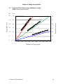
TARGET AND PIXEL SIZES VERSUS DISTANCE TO TARGET ............................................................ 50
APPENDIX A – MEASUREMENT BASICS ............................................................................................ 1
A.1 HEAT, TEMPERATURE AND IR MEASUREMENT BASICS ........................................................................ 1
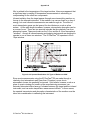
A.2 CONDUCTIVE HEAT TRANSFER ............................................................................................................. 1
A.3 CONVECTIVE HEAT TRANSFER ............................................................................................................. 3
A.4 RADIATIVE HEAT TRANSFER ................................................................................................................ 3
®
A.5 HOW THE IR FLEXCAM R2 CONVERTS RADIANCE TO TEMPERATURE ............................................... 7
APPENDIX B - DETERMINING BACKGROUND TEMPERATURE AND EMISSIVITY............... 1
B.1 PROCEDURE FOR DETERMINING BACKGROUND TEMPERATURE SETTING USING AN ALUMINUM
REFLECTOR ................................................................................................................................................. 1
B.2 PROCEDURE FOR MEASURING THE EFFECTIVE EMISSIVITY OF AN UNKNOWN EMITTER ....................... 1
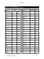
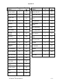
APPENDIX C – EMMISIVITY VALUES ................................................................................................. 1
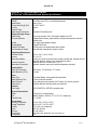
APPENDIX D – TECHNICAL SPECIFICATIONS................................................................................. 1
IR FlexCam® R2 User Manual
iii
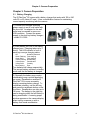
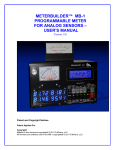
Unpacking
The IR FlexCam R2 comes in a rugged customized carrying case packed in a
heavy corrugated shipping container with foam packing.
®
Unpack all equipment and account for each item using the shipping papers.
Inspect components for damage. If damage is noted, please notify the freight
carrier and Infrared Solutions Customer Service immediately [telephone
(866)260-6237].
Operating
Manual &
Literature
Batteries
Neck Strap
IR FlexCam Pro®
Camera
Memory Card
USB Adapter
FlexView Software
Battery
Charger
Caution
Care should be taken in handling the IR FlexCam Pro® camera. Although the
radiometer is a rugged instrument, it should be handled like any sophisticated
camera equipment.
The lens is made of Germanium, a material transparent to infrared radiation. It is
coated with a multilayer antireflection coating for the 8 to 12 µm wavelength
range. It should be treated with care. To clean the lens, use lukewarm water
and mild detergent (Ivory Liquid or Liqui-Nox) and a soft cotton material. Rinse
with clean lukewarm water and dry lightly with soft clean cotton. If wiping streaks
remain, use reagent grade Acetone or reagent grade Methanol Alcohol. Soak
corner of clean, soft cotton with acetone or alcohol and wipe gently. Germanium
lenses and windows may also be cleaned using reading glasses cleaning
tissues. Rub lightly with the cleaning tissues to avoid damage to the optical
coating.
IR FlexCam® R2 User Manual
iv
1)
2)
3)
4)
5)
6)
7)
8)
9)
10)
11)
12)
13)
14)
Quick Start
Charge battery – see procedure in paragraph 3.1 on page 8.
Install charged battery in camera – see procedure in paragraph 3.2 on
page 9.
Install memory card in camera – see procedure in paragraph 3.4 on page
10.
Turn on camera – see location of Power switch, item 10 on page 2.
Set emissivity to 0.95 (factory setting) which is representative of many
targets like painted surfaces – see procedure in paragraph 5.2 on page
32.
Set background temperature to the ambient room temperature (factory
setting is 68F) – see procedure in paragraph 5.3 on page 32.
Remove lens cap and point camera toward target.
Frame the target image on the display.
Click the Scale Button – see location of Scale Button, item 16 on page 2.
Focus camera lens – see procedure in paragraph 4.2 on page 21.
Repeat steps 9 and 10 as needed.
Capture an infrared image – see procedure in paragraph 4.3 on page 22.
Read temperatures in the infrared image – see procedure, paragraph 5.4
on page 33.
Save the thermogram (infrared image) for later use – see procedure,
paragraph 4.4 on page 22.
IR FlexCam® R2 User Manual
v
Chapter 1: Camera Interfaces and Controls
Chapter 1: Camera Interfaces and Controls
Camera functionality is described in detail in chapters 2 through 6. The purpose
of this chapter is to introduce the user to the look and feel of the IR FlexCam®
R2.
The IR FlexCam® R2 has several direct access buttons, a menu system, image
display, removable memory card and video output. The buttons and menu
system are designed to be readily accessible for quick and easy operation of the
camera. The IR FlexCam® R2 has two programmable buttons that are easily
programmed for direct access to menu functions that are used most often by an
individual camera operator. The location of the camera interfaces and controls
are shown in the following paragraphs along with a description of their function.
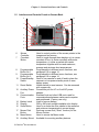
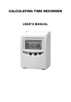
1.1
Interfaces and Controls Found on Camera Front and Top
5
4
1
5
2
3
1
2
Lens
Freeze Frame
Button
3
Video Port and
Cover
Memory Card
Slot and Cover
Neck Strap
Mount
4
5
IR FlexCam® R2 User Manual
Infrared germanium lens with manual focus.
Button used to pause and/or save an image frame,
and to toggle back to the video mode. Also used to
close out the menu page and return the camera to
an operating mode (same as an OK click).
RCA video jack used to connect camera to a TV or
video monitor, plus protective cover.
Slot for CompactFlash card and ejection button,
plus protective cover.
Pins for attaching neck and/or shoulder strap.
1
Chapter 1: Camera Interfaces and Controls
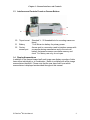
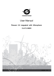
1.2
Interfaces and Controls Found on Camera Back
6
7
19
18
8
17
9
10
16
15
11
12
13
6
7
8
9
10
Mouse
Controller
Crosshair
Button
Programmable
Button No. 1
Programmable
Button No. 2
Power/Standby
Switch
11
Reset Switch
12
Auxiliary Power
Port
Communication
Ports
13
14
15
16
Battery Latch
Display
Scale Button
17
Mouse Click
Button
Menu Button
Auxiliary Mount
18
19
IR FlexCam® R2 User Manual
14
Used to control position of the mouse pointer in the
images and text menus.
Used to toggle through three displays: a) no center
crosshair or box, b) center crosshair with center
temperature, c) center crosshair with center
temperature together with box and maximum,
average and minimum box temperatures.
Programmable to different menu functions, see
paragraph 3.9 on page 14.
Programmable to different menu functions, see
paragraph 3.9 on page 14.
Used to turn camera on and off and to place the
camera in a low-power standby mode to save
battery power.
Hidden switch to reset camera. Can be accessed
with a paper clip.
Connection port for AC-to-9 volt-DC power
adapter.
Standard host and client USB ports used for
communications between camera and computer
and peripherals. (Factory use only)
Used to remove battery.
320 by 240 pixel sunlight-readable color display.
Used to re-scale the color palette to the maximum
and minimum temperatures in current image.
Performs mouse click (“Enter” function) for the
Mouse Pointer.
Used to access the Menu mode.
Available for mounting auxiliary devices.
2
Chapter 1: Camera Interfaces and Controls
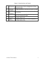
1.3
Interfaces and Controls Found on Camera Bottom
22
20
21
20
Tripod mount
21
22
Battery
Factory
access port
Standard ¼ - 20 threaded hole for mounting camera on
tripod.
7 volt lithium-ion battery for primary power.
Access port to a connector used to interface camera with
a computer during manufacture and to the coin cell
battery that powers camera nonvolatile memory and
clock. For factory use only, do not open.
1.4 Display Nomenclature
In addition to the thermal image itself each image can display a number of data
items either individually or in combination. Below is a display with all the image
nomenclature identified. Please note that the user has control over which
nomenclature is displayed as described throughout this manual.
IR FlexCam® R2 User Manual
3
Chapter 1: Camera Interfaces and Controls
13
12
11
10
14
15
9
1
2
1
2
3
4
Center Box
and its
Temperatures
Programmable
Buttons’ icons
Emissivity
5
Background
Temperature
Date
6
Time
7
8
Temperature
Units
Power Source
9
Color Palette
3
4
5
6
7
8
Center 50 by 50 pixel box and the maximum, average
and minimum temperatures in the box
Icons for the two programmable buttons, F1 and F2, and
location to click for changing the buttons’ function
Used by camera to calculate target temperatures and
location to click for changing the emissivity value
Used by camera to calculate target temperatures and
location to click for changing background temperature
Current date and location to click for changing date
Current 24 hour time and location to click for changing
time
Used to display camera temperature units and location to
click for changing the temperature units
Icon indicating AC power or battery level and location to
click to identify remaining time left with current battery
charge
Palette used in current displayed image and location to
click for cycling through the different color palettes
IR FlexCam® R2 User Manual
4
Chapter 1: Camera Interfaces and Controls
10
Palette
Temperatures
11
Center point
Temperature
Mouse Pointer
and
Temperature
Image Name
12
13
14
15
Hottest
Temperature
Coldest
Temperature
Maximum, center and minimum temperatures of the
palette and location to click to change limits of a fixed
temperature range
Average temperature of the center most group of 4 pixels
Mouse pointer and temperature at the location of the
mouse pointer
Name based on an assignable prefix, date image was
taken and a sequencing number
Temperature and location of the hottest temperature in
the image, always in red
Temperature and location of the coldest temperature in
the image, always in blue
IR FlexCam® R2 User Manual
5
Chapter 2: Camera Hardware Design Features
Chapter 2: Camera Hardware Design Features
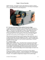
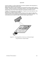
The IR FlexCam® R2 is designed to be compact, flexible, rugged and easy to
operate. It has a five-inch display module that can be positioned for optimal
viewing by the operator while the lens/sensor module is free to be rotated into
position to capture the target image. The modules can be adjusted for viewing
the display comfortably while monitoring targets in difficult positions such as on
the ceiling, hidden above high objects or hidden under low obstacles. Note in the
pictures below how the display module and the lens/sensor module can be
positioned relative to each other for optimum viewing comfort.
The modules can be adjusted so the camera display and control buttons are
positioned for comfortable desktop image analysis. The camera can also be
mounted on a tripod for continuous monitoring of a single location. See pictures
below.
IR FlexCam® R2 User Manual
6
Chapter 2: Camera Hardware Design Features
The IR FlexCam® R2 is powered with a long life lithium battery that is not subject
to charge capacity loss from the practice of partial charging. The camera can
read the remaining charge capacity of the battery and presents that value to the
operator pictorially and in terms of minutes of remaining camera run time.
IR FlexCam® R2 User Manual
7
Chapter 3: Camera Preparation
Chapter 3: Camera Preparation
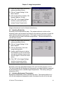
3.1 Battery Charging
The IR FlexCam® R2 comes with a battery charger that works with 100 to 240
volts 50- or 60-Hertz AC input. It has a recalibration feature for maintaining
correct capacity monitoring with the camera.
1) Connect the universal switching
power supply to an AC wall outlet with
the line cord. An adapter for the wall
outlet may be needed in some nonUSA countries. Connect the power
supply to the dual bay battery charger - model FLX 3002.
2) Insert battery into one of the battery
charger bays. Charging takes up to 3
hours. The LED indicator in front of
each bay conveys charging status.
Off:
Green Flashing:
Green Solid:
Yellow Flashing:
Yellow/Green:
Yellow Solid:
Red Flashing:
No battery detected
Fast charging
Fully charged
Recalibrating
Recalibrated
Standby
Error
Two batteries will charge sequentially.
The second battery remains in standby
mode until the first battery is charged.
3) Generally the battery may require
recalibrating once a month depending
on usage. Recalibration enables IR
FlexCam® R2 to more accurately
display remaining battery charge. To
recalibrate a battery, use the left bay
and press the recalibrate button on the
front face. Recalibration can take up to
16 hours. The battery in the right bay
can be charging while the left battery is
being recalibrated. A warning popup
window appears on the camera display
when turning a camera on with a
battery that needs recalibration.
IR FlexCam® R2 User Manual
8
Chapter 3: Camera Preparation
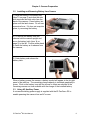
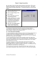
3.2
Installing and Removing Battery from Camera
1) Align the battery in the battery slot
(item 21 on page 3) such that the side
with terminals and latch slots face the
back of the camera. Press battery into
place until the latch closes. Do not use
excessive force. If it does not snap into
place, try reversing the battery.
2) To remove the battery from the
camera hold the camera upright and
move the battery latch (item 14 on
page 2) to the left. Position either hand
to catch the battery as it releases from
the camera.
3) Catch battery and release the
battery latch.
When a battery powers the camera, a battery symbol will appear in the far right
panel of the task bar. The remaining charge capacity is indicated graphically in
green. Click on the battery icon with the mouse to obtain an estimate of the
remaining camera run time available with the charge of the installed battery.
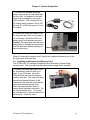
3.3 Using AC Auxiliary Power
A universal switching power supply is supplied with the IR FlexCam® R2 to
enable powering the camera from an AC source.
IR FlexCam® R2 User Manual
9
Chapter 3: Camera Preparation
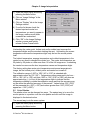
1) Connect the universal switching
power supply to an AC wall outlet with
the line cord. An adapter for the wall
outlet may be needed in some nonUSA countries. This universal AC-toDC power supply converts 100 to 240
AC-volt, 60- or 50-Hertz input to 9-volt
DC output.
2) Loosen and rotate the rubber cover
for the power port (item 12 on page 2)
out of the way. Attach the 9 DC-voltpower plug to the camera power port.
Caution: The cable plug uses an outer
sliding latch to strongly secure the plug.
Pull the latch back before attaching or
removing the plug.
When AC powers the camera an AC symbol will replace the battery icon in the
far right panel of the task bar.
3.4 Installing and Removing the Memory Card
The IR FlexCam® R2 camera is supplied with a removable CompactFlash
memory card. This card will hold several hundred images and is reusable.
1) Loosen and rotate the rubber cover
for the memory card slot (item 4 on
page 1) out of the way. Insert the
CompactFlash card into the camera
memory card slot. The card front label
should face toward the back of the
camera and the little red arrow should
point down into the camera body.
Push the card firmly into place to
ensure good electrical connection. Do
not use excessive force. Try turning
the card around if it does not press into
place easily. Close the cover.
IR FlexCam® R2 User Manual
10
Chapter 3: Camera Preparation
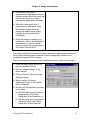
2) To remove the memory card open
the cover. Press the ejection button
down firmly to eject the card. Grab the
card and pull it from the card slot.
Close the cover.
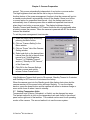
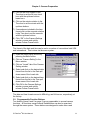
3.5 Display Brightness
The IR FlexCam® R2 display has three levels of brightness. The display can be
toggled through the three levels of brightness two ways:
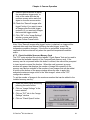
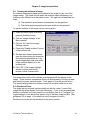
a) Changing the display brightness through the menu system:
1) Open the menu popup window by
pressing the Menu button
2) Click on “Camera Settings” in the
Menu window
3) Click on “Power” tab in the Camera
Settings window
4) Select and click on the desired
brightness – Dim, Normal, or Bright
– in the Display Brightness pull
down menu
5) Click “OK” in the Camera Settings
window or press and quickly
release Freeze Frame button
b) Adjust display brightness with one of the programmable buttons (see
paragraph 3.9 on page 14 for details on how to program a button).
You can cycle through the three levels of brightness by successively pressing the
programmed Brightness button.
Note: For maximum battery life, choose the dimmest setting that provides an
acceptable image.
3.6 Saving Power
The IR FlexCam® R2 has a power management function to extend the life of a
battery charge. One feature is to keep the intensity of the display at the
appropriate level. See paragraph 3.5 above for a discussion on selecting display
brightness. The camera has a means of limiting how long the display stays on
high brightness before the camera automatically turns the display brightness to
IR FlexCam® R2 User Manual
11
Chapter 3: Camera Preparation
normal. This occurs automatically independent of any button or mouse action.
The high brightness level can also be set to stay on continuously.
Another feature of the power management function is that the camera will go into
a standby mode where it automatically shuts off the display if there is no button
or mouse action for a specified time interval. And, the camera can be set to
automatically turn off camera power after an additional specified time interval
when there is no button or mouse action. The display brightness timeout,
Standby Timeout and Standby to Off Timeout functions are only applicable when
a battery powers the camera. When the camera is powered with AC the timeout
features are disabled.
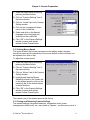
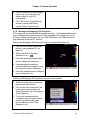
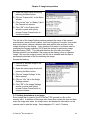
To set the power management time intervals:
1) Open the menu popup window by
pressing the Menu button
2) Click on “Camera Setting” in the
Menu window
3) Click on “Power” tab of the Camera
Setting window
4) Select and click on the desired time
interval from the list in the pull down
menus for a) “High Brightness
Timeout”, b) “Standby Timeout”
and/or c) “Standby to Off Timeout”
of the Power tab
5) Click OK in the Camera Settings
window or press and quickly
release Freeze Frame button
High Brightness Timeout limit is set to 30 seconds, Standby Timeout to 2 minutes
and Standby to Off Timeout to 5 minutes at the factory.
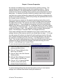
When the camera goes into the Standby mode (the display shuts down but the
camera remains on) the power button will begin flashing. To turn the display
back on, press the power button and the camera will return to whatever Image or
menu mode it was in when it went to standby.
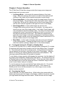
3.7 Setting Temperature Units
Temperature units (Celsius, Fahrenheit, or Kelvin) can be changed two ways.
The easiest method is to click on the temperature unit mark found in the second
panel on the right end of the task bar. This method can be used for all operating
modes of the camera. The second method is to use the menu system:
IR FlexCam® R2 User Manual
12
Chapter 3: Camera Preparation
1) Open the menu popup window by
pressing the Menu button
2) Click on “Camera Settings” in the
Menu window
3) Click on “Locale” tab in the Image
Settings window
4) Check the desired temperature
units button on the Locale tab
5) Click “OK” in the Camera Settings
window or press and quickly
release Freeze Frame button
The factory setting for temperature units is Fahrenheit (F).
3.8 Setting Date and Time
The IR FlexCam® R2 has an internal calendar and clock. The calendar is used in
naming saved images, see paragraph 5.11 on page 41. The clock is used to
record the time of day when a saved image is acquired. Both the date and time
are recorded in the image file and are accessed with the SmartView™ software
program. The Calendar tab used to set the date and time can be accessed via
the menu system or by clicking on the date or time in the Task bar, panel 4 and 5
from the left, respectively.
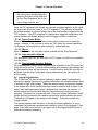
To adjust the calendar and clock via the menu system:
1) Open the menu popup window by
pressing the Menu button
2) Click on “Camera Setting” in the
Menu window
3) Click on “Calendar” tab of the
Camera Setting window
4) Click on the Date button in the
Calendar tab and adjust the
calendar in the popup window by
first selecting the month with the
right/left buttons and then click on
the day. The year can be changed
by clicking on the year at the top of
the popup window and adjusting
with the up/down buttons
IR FlexCam® R2 User Manual
13
Chapter 3: Camera Preparation
5) Click on the hour notation in the
Time box to set the 24 hour clock
hour with the up/down buttons
based on a
6) Click on the minute notation in the
Time box to set the minute with the
up/down buttons
7) If seconds are included in the time
format click on the seconds notation
in the Time box to set the seconds
with the up/down buttons
8) Click “OK” in the Camera Settings
window or press and quickly
release Freeze Frame button
The format of the date and time can be set to a number of conventions both USA
and international. This is done via the menu system:
1) Open the menu popup window by
pressing the Menu button
2) Click on “Camera Setting” in the
Menu window
3) Click on “Locale” tab of the Camera
Setting window
4) Select and click on the desired date
format from the list in the Date pull
down menu of the Locale tab
5) Select and click on the desired time
format from the list in the Time pull
down menu of the Locale tab
6) Click OK in the Camera Settings
window or press and quickly
release Freeze Frame button
The date and time formats are set to MM-dd-yy and HH:mm:ss, respectively, at
the factory.
3.9 Programmable Function Buttons
Two buttons (items 8 and 9 on page 2) are programmable to several camera
functions. All functions except Internal Recalibration can also be exercised
through the menu system. These buttons are designed to make often-used
IR FlexCam® R2 User Manual
14
Chapter 3: Camera Preparation
functions directly available by a single button push. The more frequently used
functions will vary by operator and application so it is likely that different
operators will want direct access to different functions.
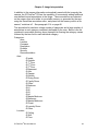
3.9.1 Programmable Button Definitions
Zoom: Used to quickly toggle between 2x zoom and normal display
settings.
Brightness: Used to quickly access the backlight brightness
adjustment: “Dim”, “Normal”, and “Bright”. Each time the function
button is pressed the next setting will take affect.
Annotation: Used to quickly access the image annotation editor.
Browse Thumbnails: Used to quickly browse thumbnails of images
stored on the compact flash card.
Palette Visible: Used to give quick access to toggling the palette bar
on and off the display.
Start Sequence: Used to quickly start the programmable image
capture (PIC) sequence.
Stop Sequence: Used to quickly stop the programmable image
capture (PIC) sequence.
Image Enhancement: Used to give quick access to cycle through the
image enhancement settings: “Off”, “Normal”, “Medium”, and “High”.
Each time the function button is pressed the next setting will take
affect.
Lens Properties: Used to quickly access the calibration range/lens
selection page.
Internal Recalibrate: Used to perform an immediate internal
calibration adjustment.
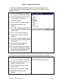
3.9.2 Assigning Programmable Buttons
Assigning a new function to the programmable buttons is easy and intuitive.
IR FlexCam® R2 User Manual
15
Chapter 3: Camera Preparation
1) Click on the function icon for either
button that is displayed in the far left
panel of the task bar. A popup
menu appears listing the functions,
with their icons, that are available to
be assigned to that button.
2) Highlight and click on the desired
new function. The function icon
displayed in the task bar will change
appropriately for that button.
All assignable functions can be assigned to either button. Electronic Zoom is
assigned to button F1 and display Brightness to button F2 at the factory.
3.10 Selecting Lens Calibration
For optimum performance on different applications, a single IR FlexCam® R2
camera can be provided with different lenses. Calibration data for each lens are
stored in the camera memory and when the lens is changed you must identify
which lens is being used.
To identify the lens type:
1) Open the menu popup window by
pressing the Menu button
2) Click on “Camera Settings” in the
menu window
3) Click on “Lens” tab in the Camera
Settings window
4) Select and click on the appropriate
lens from the Lens pull down menu
list in the Lens tab
5) Click “OK” in the Camera Settings
window or press and quickly
release Freeze Frame button
3.11 Changing Language
The IR FlexCam® R2 allows the user to change the menu and image display
language. The camera is set to English at the factory.
To change language:
IR FlexCam® R2 User Manual
16
Chapter 3: Camera Preparation
1) Open the menu popup window by
pressing the Menu button
2) Click on “Camera Settings” line of
the menu window
3) Click on “Locale” tab of the Camera
Setting window
4) Click on the Language pull down
menu on the Locale tab
5) Select and click on the desired
language in the Language pull
down list on the Locale tab
6) Click “OK” in the Camera Settings
window or press and quickly
release Freeze Frame button
3.12 Setting Mouse Speed
The speed at which the mouse moves across the display and/or changes
numerical values and the sensitivity of the mouse button to that movement can
be adjusted from slow to fast.
To adjust the mouse speed:
1) Open the menu popup window by
pressing the Menu button
2) Click on “Camera Settings” line of
the menu window
3) Click on “Mouse” tab of the Camera
Setting window
4) Highlight and drag the Mouse
Sensitivity button on the Locale tab
to the desired speed or click on the
sensitivity bar in the desired slower
or faster direction
5) Click “OK” in the Camera Settings
window or press and quickly
release Freeze Frame button
The mouse is set to the fastest speed at the factory.
3.13 Saving and Retrieving Camera Settings
The camera settings (like palette selection, temperature units, power
management, hottest point, etc.) can reside in 3 places – on the memory card, in
IR FlexCam® R2 User Manual
17
Chapter 3: Camera Preparation
the camera nonvolatile memory and in the camera operating memory. The
camera always uses the settings stored in the operating memory. When a
camera is turned-on, the setup parameters stored on the memory card are
loaded into the camera operating memory replacing any settings that may have
been there. If a camera is turned-on without a memory card or with a memory
card that has no stored setting, the camera will load the factory settings that are
stored in nonvolatile memory. These factory settings are permanent and cannot
be changed except at the factory.
After the settings are loaded into the camera operating memory they can be
changed by exercising anyone or all of the various setting functions discussed
throughout this manual. The camera uses these new settings as long as the
camera remains on. These changes are temporary and are not automatically
added to the memory card for later use. A deliberate action in the menu system
– Save Settings to Compact Flash -- must be taken to add changes to the setting
stored on the memory card. If the camera is turned off before exercising the
button, “Save Settings to Compact Flash”, the changes will be lost.
If the camera settings have been changed and you want to revert back to the
settings that are on the memory card you can reload them two ways. 1) You can
turn the camera off and back on which will load the settings stored on the card.
And 2) without turning the camera off you can load the settings on the card into
the camera by exercising the menu function – Load Settings from Compact
Flash. You can also load settings from a different card than the start-up card by
replacing the start-up card with the alternate card and exercising the menu
function – Load Settings from Compact Flash.
To save current camera setting changes to the memory card:
1) Open the menu popup window by
pressing the Menu button
2) Click on “Camera Setting” in the
Menu pop-up window
3) Click on “Save” tab of the Camera
Setting window
4) Click on “Save Settings to Compact
Flash” button in the Save tab
5) Click on “OK” in Camera Settings
window or press and quickly
release Freeze Frame button
To reload camera settings from the start-up memory card or to load camera
settings from a different card without turning the camera off:
IR FlexCam® R2 User Manual
18
Chapter 3: Camera Preparation
1) Open the menu popup window by
pressing the Menu button
2) Click on “Camera Setting” in the
Menu window
3) Click on “Save” tab of the Camera
Setting window
4) Click on “Load Settings from
Compact Flash” button in the Save
tab
5) Click on “OK” in Camera Settings
window or press and quickly
release Freeze Frame button
To load factory settings start the camera without a memory card or if the camera
is already on and must remain on use the menu system:
1) Open the menu popup window by
pressing the Menu button
2) Click on “Camera Setting” in the
Menu window
3) Click on “Save” tab of the Camera
Setting window
4) Click on “Restore Factory Settings”
button in the Save tab
5) Click on “OK” in Camera Settings
window or press and quickly
release Freeze Frame button
3.14 Video Output
The IR FlexCam® R2 can output video of the live, paused or saved images via
the video port (item 3 on page 1). This video can be displayed on a TV, video
projector or video display. It can also be recorded on a video recorder. The
output can be set to NTSC (American TV), PAL (European TV) or turned OFF via
the menu system. With the video output turned OFF the camera will use less
power, saving battery charge.
Note: If a modern projector, display or TV is used that can display in either NTSC
or PAL, use the PAL setting. NTSC projections cut off the top and bottom few
lines losing valuable display data such as the Task bar. PAL does not.
To turn on NTSC or PAL video output:
IR FlexCam® R2 User Manual
19
Chapter 3: Camera Preparation
1. Open the menu popup window by
pressing the Menu button
2. Click on “Camera Settings” in the
Menu window
3. Click on “Locale” tab in the Camera
Settings window
4. Check the NTSC or PAL button in
the Locale tab
5. Then select the Power tab and
check the Video Output Enabled
button
6. Click “OK” on the Camera Settings
window or press and quickly
release Freeze Frame button
To turn on and off the video output:
1. Open the menu popup window by
pressing the Menu button
2. Click on “Camera Settings” in the
Menu window
3. Click on “Power” tab in the Camera
settings window
4. Check the Video Output Enabled
button to turn video output on,
uncheck it to turn video output off
5. Click “OK” on the Camera Settings
window or press and quickly
release Freeze Frame button
Video is set to NTSC and OFF at the factory.
IR FlexCam® R2 User Manual
20
Chapter 4: Camera Operation
Chapter 4: Camera Operation
The IR FlexCam® R2 has three image modes (live-image, pause-image and
saved-image) and one menu mode.
•
Live-Image Mode -- In this mode the camera displays a (live) video
image. When the camera is first turned on it starts in this mode and will
continue in this mode until the operator exercises a mode change.
•
Pause-Image Mode – In this mode a single live image frame is frozen on
the camera display. By pressing the freeze frame button (item 2 page 1)
for less than 1/2 second, the camera goes into this Pause-Image mode
and the word “Paused” appears in the upper left corner of the display.
•
Saved-Image Mode – In this mode images are saved on the
CompactFlash card as well as frozen on the display. An image can be
saved from any one of the image modes – Live-Image, Pause-Image, and
even resaved from the Saved-Image mode. From any of the three modes
pressing the Freeze Frame button and holding it down for more than 1/2
second puts the camera in this mode. This mode also applies when a
previously saved image is retrieved and displayed on the camera display.
After an image is saved, press and release the Freeze Frame button in 1/2
second or less to return to Live-Image mode.
•
Menu Mode -- In this mode, information and setup menus are displayed
on the camera display. Pressing the Menu button (item 18 on page 2)
starts this mode by opening a popup menu on the camera display.
4.1 Turning the Camera On, Off and to a Standby Mode
To turn the IR FlexCam® R2 on, install a charged battery (paragraph 3.2 on page
9) and press the Power button located to the left of the display (item 10 on page
2). The camera will start in the live-image mode. During start-up the FlexCam
logo will appear first and then a task bar at the bottom of the display. While the
task bar is showing, the camera stabilizes and performs self-calibration. This
start-up process will take about 30 seconds to complete.
To save battery charge capacity while keeping the camera on, turn the display off
by pressing and immediately releasing the Power button. The camera will go into
a Standby mode and the power button will flash. Press the power button again to
turn the display back on and the camera will return to whatever Image or menu
mode it was in when it was put in standby.
To turn the camera off, press and hold the Power button down for 1.5 seconds.
Any paused unsaved image on the display will be lost. If the camera is in
Standby mode it must first be returned to one of the Image or menu modes,
before it can be turned off.
4.2 Focusing the Camera
The IR FlexCam® Pro uses manual focus. While holding the camera with both
hands and observing the live-image on the display, rotate the lens focus ring with
your right hand index finger as shown below. Rotate the lens until the image
IR FlexCam® R2 User Manual
21
Chapter 4: Camera Operation
appears sharpest. Only slight movement will typically be required to optimize
focus. You may find it helpful to electronically zoom in the image (see paragraph
5.10 on page 40) and focus on the enlarged area.
4.3 Causing a Live-Image to Pause without Saving the Image
To capture and display a single frame (Pause-Image mode) while in the LiveImage mode press and immediately release the Freeze Frame button (item 2 on
page 1). The current Live-Image frame is frozen on the display and the word
“Paused” will appear in the upper left corner of the display. This frame will
remain on the display until a) the Freeze Frame button is pressed again to put
the camera back into the Live-Image mode or b) a previously saved image is
retrieved form the memory card and displayed on the camera display.
When leaving the Paused-Image mode, the captured frame will be lost unless it
is saved as described in the next paragraph 4.4 below. If a paused image is on
the display when a saved image is being retrieved from memory a popup window
will appear asking if you want to save the paused image giving you a second
chance not lose the image.
4.4 Saving an Image
Images can be saved two ways. The easiest way is to press the Freeze Fame
button down for 1/2 second. Images from any one of the three image modes,
Live-Image, Paused-Image or Saved-Image will be saved to the memory card. In
the Live-Image mode the image is saved to the memory card as well as frozen
on the display. In the Paused-Image mode the Paused-Image is saved to the
memory card. And in the Saved-Image mode the saved image is re-saved to the
memory card.
When a saved image is modified and re-saved a popup window appears
providing the operator two choices. 1) Save the image as a new image with the
same name as the original image only with an extra letter (a, b, c, etc.) added to
the name. Or 2) replace the original saved image with the modified image.
IR FlexCam® R2 User Manual
22
Chapter 4: Camera Operation
The second method, via the menu system, can also be exercised from any one
of the three image modes:
1) Open the menu popup window by
pressing the Menu button
2) Click on “Save Image” in the Menu
window
Whenever an image is saved the image name is added to the display in the
upper left corner. See paragraph 5.11 on page 41 for details on the saved image
name.
It is recommended that you keep no more than 300 images and preferably less
than 50 on your camera’s compact flash card. It is suggested that you often
move the images from the CompactFlash card to your desktop or laptop PC.
4.5 Retrieving a Saved Image
All the saved images on the memory card in the camera can be seen on the
camera display as thumbnail images in pages of nine at a time. For a given
prefix the images will be presented in reverse order from the order in which they
were taken. The first image on the first page will be the last saved image of a
prefix grouping except in the case when you modify and resave an already saved
image. A modified and resaved image if saved as a new image will be places
next to the initially saved image. The prefix groupings are arranged in reverse
alphabetical order. Any one of the thumbnails can be highlighted and opened to
fill the whole display. Saved images can be retrieved in two ways:
a) With the menu system:
1) Open the menu popup window by
pressing the Menu button
2) Click on “Browse Images” in the
Menu window
3) Select page with the desired image
by scrolling through the pages with
the right/left arrows in the Task bar
4) Double click on image or highlight it
and click on the “Open” button in
the Task bar
IR FlexCam® R2 User Manual
23
Chapter 4: Camera Operation
b) With one of the programmable buttons assigned to Browse images
(see paragraph 3.9 on page 14 for details on how to program buttons):
1) Press the programmable Browse
Images button
See Browse Images window above
2) Select page with the desired image
by scrolling through the pages with
the right/left arrows in the Task bar
3) Double click on image or highlight it
and click on the “Open” button in
the Task bar
Note: With this second technique you can close the open image and return
directly back to the thumbnail images by pressing the Browse Images
programmable button.
4.6 Deleting Saved Images
Saved images on a memory card can be seen on the camera display as
thumbnail images in pages of nine at a time. Any one of the thumbnails can be
deleted two ways. Also all images can be deleted at once.
a) Delete a single image via the menu system:
1) Open the menu popup window by
pressing the menu button
2) Click on “Browse Images” in the
menu window
3) Select page with the desired image
by scrolling through the pages with
the right/left arrows in the Task bar
4) Highlight desired image and click on
the “Delete” button in the Task bar
5) Confirm the deletion by clicking on
“Yes” in the popup window
6) Click on “Close” button in the
Browse window or press and
quickly release Freeze Frame
button
IR FlexCam® R2 User Manual
24
Chapter 4: Camera Operation
b) Delete a single image with one of the programmable buttons assigned
to Browse images (see paragraph 3.9 on page 14 for details on how to
program a button):
1) Press the programmed Browse
Image button
See Browse Images window above
2) Select page with the desired image
by scrolling through the pages with
the right/left arrows in the Task bar
3) Highlight the desired image and
click on the “Delete” button in the
Task bar
4) Confirm the deletion by clicking on
“Yes” in the popup window
5) Click on “Close” button in the
Browse window or press and
quickly release Freeze Frame
button
All images on the memory card can be deleted at one time by:
1) Open the menu popup window by
pressing the menu button
2) Click on “Camera Settings” in the
menu window
3) Click on “Files” tab in the “Camera
Settings” window
4) Click on the “Delete All” button in
the “Files” tab
5) Confirm the deletion by clicking on
“yes” in the popup window
6) Click “OK” in the Camera Settings
window or press and quickly
release Freeze Frame button
4.7 Programmable Image Capture (PIC)
Programmable Image Capture (PIC) is an in-camera capability to record a
sequence of several images without continued user input. The user specifies the
number of images to be captured and the time interval between images. The
minimum time interval is 1 second and the maximum is 10,000 seconds (about 2
and1/2 hours). The minimum number of frames is 1 and the maximum number is
IR FlexCam® R2 User Manual
25
Chapter 4: Camera Operation
10,000. The actual number of saved images is also limited by the capacity of
your CompactFlash card. Each image captured during a programmed sequence
will be stored in the same manner and with the same name conventions as
individual saved images (See section 5.11 on page 41).
There are two ways of starting the sequence, manually-triggered and
temperature-triggered. Manual startup PIC begins taking images instantly
following exercising the start function. Temperature-triggered PIC enables the
user to choose a single camera temperature measurement point to trigger the
image taking sequence. Measurement points include hot and cold cursors,
center point, mouse point, and the center box average temperature.
Triggering can be based on the point having a temperature either greater than or
less than a specified value. These temperatures are monitored at 30 Hertz but
displayed at 2 Hertz. The PIC start is triggered off the displayed values and
therefore will start with a maximum delay of about ½ second. The minimum and
maximum values for the temperature trigger point will be limited to the camera
calibration range (-20 to 100C or -4 to 212F).
Like the manually triggered PIC, temperature triggered PIC also starts following
the exercising of the start function but image taking is delayed until the specified
temperature condition occurs. A subset of the temperature triggered sequence
is; 1) that images are taken continuously after the sequence starts even though
the temperature trigger condition may cease to exist and 2) the sequence pauses
after the temperature trigger condition ceases to exist and resumes automatically
once the temperature trigger condition re-occurs.
4.7.1 Configuring Manual Startup PIC
1. Open the menu popup window by
pressing the menu button
2. Click on “Image Settings” in the
menu window
3. Click on “PIC” tab in the “Image
Settings” window
4. Use the “Max Images” right/left
arrows to adjust the number of
images, or click on the value and
use the up/down mouse action and
click again to close the mouse
action
IR FlexCam® R2 User Manual
26
Chapter 4: Camera Operation
5. Use the “Interval (sec)” right/left
arrows to adjust the number of
seconds between images, or click
on the value and use the up/down
mouse action and click again to
close the mouse action
6. Highlight the “Manual” button
7. Click “OK” in the “Image Settings”
window or press and quickly
release Freeze Frame button
4.7.2 Configuring Temperature-Triggered PIC
1. Open the menu popup window by
pressing the menu button
2. Click on “Image Settings” in the
menu window
3. Click on “PIC” tab in the “Image
Settings” window
4. Use the “Max Images” right/left
arrows to adjust the number of
images, or click on the value and
use the up/down mouse action and
click again to close the mouse
action
5. Use the “Interval (sec)” right/left
arrows to adjust the number of
seconds between images, or click
on the value and use the up/down
mouse action and click again to
close the mouse action
6. Highlight the “Temperature” button
7. Highlight the measurement point
button: “Hotpoint”, “Coldpoint”,
“Centerpoint”, “Mouse”, or “Box
Avg”.
8. Highlight the “Over” or “Under”
button.
IR FlexCam® R2 User Manual
27
Chapter 4: Camera Operation
9. Use the right/left arrows to adjust
the temperature trigger point, or
click on the value and use the
up/down mouse action and click
again to close the mouse action
10. Check the “Save all images after
trigger” button if you want to save
all images after the initial trigger,
uncheck it if you want only images
that meet the trigger criteria
11. Click “OK” in the “Image Settings”
window or press and quickly
release Freeze Frame button
Note: If the “Save all images after trigger” button is checked, an image will be
captured after each time interval, following the initial trigger, even if the
temperature condition changes. If the button is unchecked, images will be
captured at the time interval only when the specified temperature condition
exists.
4.7.3 Check Available Space on Memory Card
The “PIC” setup window has a button labeled “Check Space” that can be used to
determine the available capacity of the CompactFlash memory card. If the
memory card is not present when this button is clicked, the user will be prompted
to insert a card or cancel the function. When the card is present, a popup
window will appear that displays the number of image files currently on the
memory card and an estimate of the number of new images that can be added.
A button at the bottom of the popup window allows the user to apply this
estimated maximum image count to the “Max Images” value on the “PIC”
configuration window.
To set the number of images to the maximum number that can be added to the
installed memory card by:
1. Open the menu popup window by
pressing the menu button
2. Click on “Image Settings” in the
menu window
3. Click on “PIC” tab in the “Image
Settings” window
4. Click on “Check Space” button
IR FlexCam® R2 User Manual
28
Chapter 4: Camera Operation
5. Click on “Save ### to Max Images”
button only if you want the max
value to apply to your PIC
configuration
6. Click “OK” in the “Image Settings”
window or press and quickly
release Freeze Frame button
4.7.4 Starting and Stopping a PIC Sequence
PIC sequences can be started and stopped two ways; 1) A programmable button
can be assigned the start/stop function (see paragraph 3.9 on page 14), and 2)
the menu popup window has a line item “Start Sequence” and “Stop Sequence”
that starts and stops the PIC function.
Starting and Stopping a PIC sequence using a programmable button by:
1. Click on one of the programmable
buttons. (see paragraph 3.9 on
page 14)
2. Select and click on the Start
Sequence icon -- “ ”
3. Press the selected programmable
button to begin the sequence
4. If desired press the selected
programmable button again to stop
the sequence before completion
5. Press the selected button to begin a
second sequence, etc.
Starting and Stopping a PIC sequence using the menu system:
1. Open the menu popup window by
pressing the menu button
2. Click on the “Start Sequence” line
in the menu popup window, the
“Start Sequence” line will change to
“Stop Sequence”
3. To stop the sequence before
completion open the menu popup
window by pressing the menu
button and click on the “Stop
Sequence” line
IR FlexCam® R2 User Manual
29
Chapter 4: Camera Operation
4. To start a second sequence, open
the menu popup window again by
pressing the menu button and click
on the “Start Sequence” line in the
menu popup window, etc.
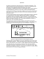
Once the PIC sequence has started, an onscreen progress indicator at the top of
the display will show the status of your PIC sequence. The indicator will display
the current number of collected images out of the total number configured for the
PIC sequence. If the PIC sequence is a temperature triggered configuration the
status indicator will display “waiting” until the trigger condition is observed.
4.7.4.1 Freeze Frame Button
While in PIC mode, the Freeze Frame button will not pause and un-pause an
image. However, it will continue to act as an “OK” button for camera operations
(for example, as in accepting a value change for palette settings).
4.7.4.2 Menus
While in PIC mode, the only menu option available will be “Stop Sequence.”
4.7.4.3 Auto-annotation Wizard
The annotation wizard will not auto-start for PIC images, and will not be available
from the menu.
4.7.4.4 Programmable Function Buttons
All programmable Function button options will be selectable in the PIC mode, but
some will not be active. Function buttons dealing with property page settings and
the thumbnail browser will not be active. Function buttons which do not bring up
windows, such as zoom, brightness, image enhancement, etc. will continue to
work normally.
4.8 Internal Recalibration
The IR FlexCam® R2 has an internal calibration feature where it automatically
adjusts the camera electronics to produce uniformity in the infrared detector array
to maintain a high quality image. When the camera senses a significant change
in the temperature of the camera electronics and/or detector array or when it has
seen a very high temperature target it automatically exercises this function. A
shutter closes and the individual detector offsets and readout electronics are
adjusted. This takes two to three seconds. During an internal calibration a weak
double click will be heard in the camera and a popup window showing the word
“Calibrating” will appear in the image on the display. During this process the
image is frozen.
The camera operator has the option of forcing an internal calibration to occur
immediately by pressing a programmed calibration button (See paragraph 3.9 on
page 14 for instructions on how to program one of the programmable buttons to
exercise the internal calibration).
IR FlexCam® R2 User Manual
30
Chapter 5: Image Interpretation
Chapter 5: Image Interpretation
Image settings such as color palette, scaling, temperature units, pixel
temperature markings, emissivity and the like can be changed to show different
information about an image. Changes can be made to these settings while the
camera is in any of the three image modes. Setting changes made with the
camera in the Live-Image mode or Paused-Image mode will apply to images in
those modes and to any image saved from those modes as long as the camera
remains on. When the camera is turned off any setting changes not saved to the
memory card will be lost. See paragraph 3.13 on page 17 on how to save setting
changes to the memory card.
Changes made while the camera is in the Saved-Image mode will apply only to
that specific image. Once the camera mode is returned to Live-Image mode or
Paused-Image mode the settings in place when the camera was last in either of
those modes will again apply.
If a new saved image is retrieved from the memory card, the settings of the new
retrieved image and any changes to it will apply to that image only. Once an
image has been modified from its previous saved state it can be re-saved
replacing the previous image or saved as a new image (see paragraph 4.4 on
page 21). Saved images that have been changed and not resaved will have an
asterisk (*) attached to their name while the image is showing on the display.
The asterisk is used to warn the camera operator that the image settings have
been changed and that they will be lost if the image is not resaved.
5.1 Adjusting Image Enhancement
Image enhancement is a feature that can reduce the electronic noise in an image
by averaging consecutive frames. This enhancement applies to real-time images
and images saved from real-time while the feature is on. It can not be applied to
images after they are saved. The amount of Image Enhancement can be
adjusted according to user preference. The available settings are, Off, Normal,
Medium, and High. The image quality will improve with each increase in image
enhancement; however, the image response time will be reduced accordingly.
(Higher settings are more likely to show blurring on moving targets)
Image enhancement can be adjusted two ways. If one of the programmable
buttons is activated to Image Enhancement, press the Image Enhancement
button (item 8 and 9 on page 2) to cycle through the four settings.
With the menu system:
IR FlexCam® R2 User Manual
31
Chapter 5: Image Interpretation
1) Open the menu popup window by
pressing the Menu button
2) Click on “Image Settings” in the
Menu window
3) Click on the setting of choice: Off,
Normal, Medium, or High.
4) Click “OK” in the Image Settings
window or press and quickly
release Freeze Frame button
Image enhancement is set to Normal at the factory.
5.2 Adjusting Emissivity
Emissivity can be adjusted two ways. The easiest method is to click on the
emissivity value, second panel from the left in the task bar, and raise or lower the
value with the up/down mouse action. Click again to close the mouse action.
This method can be used for all three image-modes. The second method is to
use the menu system:
1) Open the menu popup window by
pressing the Menu button
2) Click on “Image Settings” in the
Menu window
3) Click on “Emissivity” tab in the
Image Settings wind
4) Use the right/left arrows to adjust
the Emissivity or click on the value
and use the up/down mouse action
and click again to close the mouse
action
5) Click “OK” in the Image Settings
window or press and quickly
release Freeze Frame button
Emissivity values are adjustable between 0.01 and 1.00 with precision of 0.01.
This value along with the background temperature and target radiation measured
by the camera is used to calculate target temperatures. The factory setting for
emissivity is 0.95.
5.3 Adjusting Background Temperature
Background temperature can be specified two ways. The easiest method is to
click on the background temperature value, third panel from the left in the task
IR FlexCam® R2 User Manual
32
Chapter 5: Image Interpretation
bar, and raise or lower the value with the up/down mouse action. Click on the
background temperature value again to close the mouse action. This method
can be used for all three image modes. The second method is to use the menu
system:
1) Open the menu popup window by
pressing the Menu button
2) Click on “Image Settings” in the
Menu window
3) Click on “Emissivity” tab in the
Image Settings window
4) Use the right/left arrows to adjust
the Background Temp or click on
the value and use the up/down
mouse action and click again to
close the mouse action
5) Click “OK” in the Image Settings
window or press and quickly
release Freeze Frame button
This background temperature along with emissivity and target radiation
measured by the camera will be used to calculate target temperatures. The
factory setting for background temperature is 68°F.
5.4 Pixel Temperature Readings
Four spot temperatures and the maximum, minimum and average temperature in
a center box area can be displayed on the image in any one of the three
operating modes. These temperatures are monitored at 30 Hertz but displayed
at 2 Hertz to make them more readable.
The spot temperatures are marked with a crosshair except in the case of the
mouse, which is marked by the very tip of the mouse arrow. Note that the mouse
arrow may change direction when it approaches a display edge. But it always
marks the pixel at its very tip.
The easiest method for turning on and off the center point and center box
temperature readings is to use the Crosshair button (item 7 on page 2). This
button toggles from a) no center point and no center box, to b) center point only,
to c) center point and center box, and back to a).
The center box and center point, along with the hottest spot, coldest spot and
mouse pointer temperature value, can be turned on or off via the menu system:
IR FlexCam® R2 User Manual
33
Chapter 5: Image Interpretation
1) Open the menu popup window by
pressing the Menu button
2) Click on “Image Settings” in the
Menu window
3) Click on “Display” tab in the Image
Settings window
4) From the list shown check the
desired spot and center box
temperatures you want to appear in
the image, make sure all those
unwanted are unchecked
5) Click “OK” in the Image Settings
window or press and quickly
release Freeze Frame button
Unchecking the center point, hottest spot and/or coldest spot removes the
temperature digits and the crosshair marking the spot. Unchecking the mouse
temperature removes the temperature digits only and not the mouse pointer
itself.
The hottest temperature, average temperature and coldest temperature in the
center box are used to describe the center box. The center box dimensions are
50 pixels by 50 pixels or a little more than 1/8 of the full image area. Unchecking
the center box removes the box, temperature names and temperature digits.
The factory setting has center point temperature and mouse temperature in
image, but the hottest point, coldest points and center box turned off.
The calibration range of -20C to 100C (-4F to 212F) is extended with
approximate values by 10C (18F). Temperature values measured to be from 20C to -30C (-4F to -22F) and from 100C to 110C (212F to 230F) will show an
approximate sign (~) in front of the temperature digits to indicate that the
temperature reading is outside the calibration range and that the accuracy may
not be within the specified accuracy of the camera. Values below -30C (-22C)
will be presented as <-30C (<-22F) and values greater than 110C (230F) will
appear as >110C (>230F).
5.5 Color Palettes
The palette colors can be changed two ways. The easiest way is to move the
mouse pointer to a position over the color palette and click until the image is
displayed in the desired colors.
The second way is via the menu system:
1) Open the menu popup window by
pressing the Menu button
IR FlexCam® R2 User Manual
34
Chapter 5: Image Interpretation
2) Click on “Image Settings” in the
Menu window
3) Click on “Palette” tab in Image
Settings window
4) Select and click on the desired
palette from the list in the Palette
pull down menu on the Palette tab
5) Click “OK” in the Image Settings
window or press and quickly
release Freeze Frame button
The factory palette setting is Blue-Red.
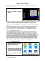
5.6 Scaling the Color Palette Temperatures
Scaling of the color palette to image temperatures can be divided into three
categories:
a) Auto scaling where the palette temperatures are updates to the maximum and
minimum temperatures in the image at a regular time interval. If the center
box feature is on the image, auto scaling is done based on the temperatures
in the box and not on the whole image. This feature allows the camera
operator to eliminate an area in the image that is very hot or very cold but of
little interest.
The time between successive auto scaling is adjustable. For some operators
if the target temperatures are changing fairly rapidly, fast auto scaling can be
disconcerting. And for others if the time between auto scaling is long it too
can be disconcerting. With the IR FlexCam® R2 this timing is adjustable from
¼ second to 10 seconds.
b) Manual scaling by pressing the scaling button to fix the temperature range
based on the maximum and minimum temperatures in the image at the time
scaling is set. If the center box feature is on the image, like in auto scaling,
the scaling is done based on the temperatures in the box and not on the
whole image.
c) Scaling to an arbitrary fixed temperature span.
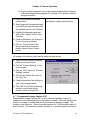
Auto scaling is exercised via the menu system:
IR FlexCam® R2 User Manual
35
Chapter 5: Image Interpretation
1) Open the menu popup window by
pressing the Menu button
2) Click on “Image Settings” in the
Menu window
3) Click on “Palette” tab in the Image
Setting window
4) Check the “Automatic Adjustment”
button on the Palette tab
5) Select and click on the desired time
interval between auto scaling from
the list in the “Adjustment Interval”
pull down menu on the Palette tab
6) Click “OK” in the Image Settings
window or press and quickly
release Freeze Frame button
The factory setting has auto scaling turned on to ½ second.
Manual re-scaling of the color palette to the maximum and minimum
temperatures in an image is accomplished by pressing the Scale Button (item16
on page 2). This can be exercised at any time in any one of the three image
modes. The scaling is then fixed to the temperatures in that image at the time rescaling occurs. If the image temperatures change again and the camera is not in
Auto Scale mode the button must be pressed again if the palette is to remain
scaled to the maximum and minimum temperatures in the image.
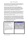
Setting the scaling to an arbitrary fixed temperature span can be accomplished
two ways. If the palette temperature scale is showing on the display, the easiest
method is to change the maximum, minimum or center point temperature values
of the color palette.
1) Highlight any one of the three
palette temperature values to begin
a change.
2) If the palette range minimum or
maximum temperature is
highlighted, using the up/down
mouse action will change the
highlighted temperature and thus
the palette range (span). The
center point (level) temperature will
also change accordingly.
IR FlexCam® R2 User Manual
36
Chapter 5: Image Interpretation
3) If the center point (level)
temperature is highlighted, using the
up/down mouse action will move the
center point (level) up or down
keeping the range (span) constant.
4) When the center point (level)
temperature is highlighted, using
the left/right mouse action will
change the palette range (span),
leaving the center point (level)
unchanged.
5) Once the change is made to your
satisfaction, click on the highlighted
temperature to close the mouse
action (or press and quickly release
the Freeze Frame button).
This feature allows the professional camera operator to adjust span and level on
the fly while panning targets of special interest creating high contrast in the
temperature ranges of those targets.
The second method of setting a fixed temperature span is via the menu system:
1) Open the menu popup window by
pressing the Menu button
2) Click on “Image Settings” in the
Menu window
3) Click on “Palette” tab in the Image
Settings window
4) Make sure the “Automatic
Adjustment” button in the Palette
tab is unchecked
5) Set the fixed temperatures by either
of two ways:
a) Set the maximum and minimum
temperature in the Palette
Range box of the Palette tab, or
b) Set the center point temperature
and span width in the Palette
Range box of the Palette tab
IR FlexCam® R2 User Manual
37
Chapter 5: Image Interpretation
6) Click “OK” in the Image Settings
window or press and quickly
release Freeze Frame button
Note: Fixed temperature span widths can not be set less than 5C or 9F.
5.7 Palette Saturation Colors
Colors are linearly mapped to temperature in all three image modes and for both
fixed and auto scaling of the palette temperatures to color. Scaling to the
maximum and minimum temperatures, whether auto or manual, uses the full
color palette to portray the temperatures in the image on the display at the time
the scaling occurs.
The same scaling of temperatures with color is maintained until a re-scaling
occurs. Following a re-scaling, if the camera measures a temperature greater
than the palette maximum temperature and/or a temperature lower than the
lowest palette temperature the pixels with these measured extreme temperature
will appear in saturation colors. These colors, shown in the table below, appear
on the ends of the palette color bar in the image.
Color Palette*
High Temperature
Saturation Color
Low Temperature
Saturation Color
Grayscale
Red
Blue
Grayscale Inverted
Red
Blue
Blue-red
White
Black
High-contrast
Blue-green
Dark Brown
Hot Metal
White
Black
Ironbow
Green
Tan
Amber
Red
Blue
Amber Inverted
Red
Blue
* Color palettes include grayscale palettes.
If the maximum temperature of an image drops and/or the minimum temperature
rises after a scaling, some palette colors or shades of color will not be used in the
image until re-scaling occurs.
5.8 Hiding Color Palette and Task Bar
Both the task bar and palette can be removed from the display thus opening the
entire display for viewing the image. By activating the Auto-hide Task Bar
function, the task bar can be set to automatically disappear within 3 seconds if
the mouse is moved off the task bar or if the mouse remains stationary on the
task bar. This function is turned on via the menu system:
IR FlexCam® R2 User Manual
38
Chapter 5: Image Interpretation
1) Open the menu popup window by
pressing the Menu button
2) Click on “Image Settings” in the
Menu window
3) Click on “Display” tab in the Image
Settings window
4) Check the “Auto-hide Task Bar”
button to turn the function on and
uncheck it to turn it off
5) Click “OK” in the Image Settings
window or press and quickly
release Freeze Frame button
To make the task bar reappear with the Auto-hide function turned on move the
mouse to the bottom of the display.
The palette can be removed from the display two ways. The easiest way is to
assign “Palette Visible” to one of the programmable buttons (items 8 and 9 on
page 2) which will toggle the palette on and off the display. (See paragraph 3.9
on page 14 for details on how to program a button.)
The second way to remove the palette is via the menu system:
1) Open the menu popup window by
pressing the Menu button
2) Click on “Image Settings” in the
Menu window
3) Click on “Display” tab in the Image
Settings window
4) Uncheck the “Temperature Scale”
button in the Display tab to remove
the Palette and pallet temperature
sale from the image, check it to add
them to the image
5) Click “OK” in the Image Settings
window or press and quickly
release Freeze Frame button
The factory setting has the Pallet and pallet temperature scale showing and the
Auto-Hide Task Bar function turned off.
IR FlexCam® R2 User Manual
39
Chapter 5: Image Interpretation
5.9 Creating an Isotherm in Image
An isotherm temperature band can be added to the image for any one of the
image modes. The pixels that fall within the isotherm span will appear in an
isotherm color different from the palette colors. The span can be specified two
ways:
a) The maximum and minimum temperatures can be specified.
b) The center point temperature and span width can be specified.
To add an isotherm to the image via the menu system:
1) Open the menu popup window by
pressing the Menu button
2) Click on “Image Settings” in the
Menu window
3) Click on “Iso” tab in the Image
Settings window
4) Check the “Enable Isotherm” button
in the Isotherm tab
5) Set desired isotherm temperature
span by either setting the maximum
and minimum temperatures or the
center temperature and span width
in the Isotherm Span box of the
Isotherm tab
6) Click “OK” in the Image Settings
window or press and quickly
release Freeze Frame button
The temperature limits of the isotherm are displayed with the palette in the
image. These isotherm temperature limits can be adjusted by clicking on them
and using the mouse up/down action. Click again to close the mouse action.
The factory settings have the isotherm turned off and span width set to zero.
5.10 Electronic Zoom
The image can be zoomed in electronically so that the center ¼ area of the
image fills the whole display (2x in both directions). If one of the programmable
buttons is activated for zoom, press the zoom button (item 8 or 9 on page 2) to
toggle between zoom and normal when in any of the three image modes. (See
paragraph 3.9 on page 14 for details on how to program a button.)
Electronic zoom can also be activated via the menu system:
IR FlexCam® R2 User Manual
40
Chapter 5: Image Interpretation
1) Open the menu popup window by
pressing the Menu button
2) Click on “Image Settings” in the
Menu window
3) Click on “Display” tab in the Image
Settings window
4) Check the “Zoom Image” button in
the Display tab
5) Click “OK” in the Image Settings
window or press and quickly
release Freeze Frame button
Electronic zoom is set to normal and assigned to button F1 at the factory.
5.11 Naming an Image
Whenever an image is saved, the image name is added to the display in the
upper left corner. It consists of a prefix with zero to three alphanumeric
characters followed by an eight digit date (yyyymmdd), then an underscore, and
a four digit sequencing number. The prefix is found in the memory card and
based on what was stored last on the card. If a new memory card with no stored
prefix is used to store an image, the prefix “IR” found in the camera nonvolatile
memory will be used. A prefix editor, found in the Files tab of the Camera
Settings menu, provides a means for changing the prefix.
5.11.1 Changing the Image File Prefix
To change the prefix used in the saved image name:
1) Open the menu popup window by
pressing the Menu button
2) Click on “Camera Settings” in the
Menu window
3) Click on “Files” tab in the Camera
Settings window
4) Open Prefix Editor by clicking on
the “Edit” button of the Files Prefix
line in the Files tab
5) If you want no prefix highlight the
existing prefix and delete it by
clicking on “Backspace”, or
6) Select and click on up to three
alphanumeric characters one at a
time in sequence from the table
IR FlexCam® R2 User Manual
41
Chapter 5: Image Interpretation
7) Click on “OK” in the Prefix Editor
window”
8) Click “OK” in the Camera Settings
window or press and quickly
release Freeze Frame button
5.11.2 Resetting the Image File Sequence Number
To change the File Sequence Number used in the saved image name:
1) Open the menu popup window by
pressing the Menu button
2) Click on “Camera Settings” in the
Menu window
3) Click on “Files” tab in the Camera
Settings window
4) Click on the “Reset” button next to
the File Sequence number.
5) Click “OK” in the Camera Settings
window or press and quickly
release Freeze Frame button
5.12 Camera Descriptive Information
Data describing the cameras are presented in two places -- the Camera Info
window of the main menu and the Info tab of the Image Settings window. The
Camera Info window presents data describing the current camera. The
Information (Info) tab of the Image Settings window presents data describing the
camera used to capture the image currently shown on the display of the current
camera. The image, although shown on the current camera, may have been
taken with a different camera.
The Camera Info window has two tabs, Info and Battery. The Info tab lists the
camera serial number, software versions, lens description, number of image files
on the memory card and the used and free space on the memory card. The
second tab, entitled Battery, shows the power source, battery or AC, remaining
battery charge, battery manufacturer, serial number and number of discharge
cycles.
Acquire the Camera Info data by:
IR FlexCam® R2 User Manual
42
Chapter 5: Image Interpretation
1) Open the menu popup window by
pressing the Menu button
2) Click on “Camera Info” in the Menu
window
3) Click on the “Info” or “Battery” tab in
the Camera Info window
4) Click “OK” in the Camera Info
window or press and quickly
release Freeze Frame button to
close the window
The Info tab of the Image Settings window presents the name of the camera
manufacturer, camera model number, lens focal length and f-number, lens model
and serial number, camera calibration date and capture date and time for the
image showing on the display. It also presents the version of software used for
managing the camera operation (OCA) and the version for performing image
data processing (DSP). This data and therefore the Info tab in the Image
Settings window is not available if the image on the display is live or a paused
image. But once the image is saved, the Info tab is available and this data is
permanently attached to the file containing the image.
Acquire this data by:
1) Retrieve or save an image to the
camera display
2) Open the menu popup window by
pressing the Menu button
3) Click on “Image Settings” in the
Menu window
4) Click on “Info” tab in the Image
Settings window
5) Click “OK” in the Image Settings
window or press and quickly
release Freeze Frame button to
close the window
5.13 Adding Annotations to an Image
Every image that is saved by the IR FlexCam® R2 is saved to a file on the
memory card. In addition to the image data, these files contain the time and date
when the image was taken, the image name, and descriptive information on the
camera used to take the image. See paragraphs 5.11 and 5.12 above.
IR FlexCam® R2 User Manual
43
Chapter 5: Image Interpretation
In addition to the camera information automatically saved with the image by the
camera, the IR FlexCam® R2 has the capability of conveniently adding additional
user defined textual annotations to the image. These annotations are selected
on the camera from a list either in nonvolatile memory or generated by the user
using the SmartView annotation editor, and placed on the memory card in a file
named, “notations.txt”. See paragraph 5.14 on page 48.
The annotation list can have a large number of categories and a large number of
annotations in each category completely definable by the user. Below is the list
contained in nonvolatile memory as an example list showing the category names
followed by the item list for each individual category.
Categories:
Area
Location
Compass
Description
Problem
Severity
Recommendation
Area
О Inside
О Outside
О 1st Floor
O 2nd Floor
O 3rd Floor
O Basement
O Attic
O Garage
O Kitchen
O Dining Room
O Family Room
O Office
O Bedroom
O #1
O #2
O #3
O #4
O Master Bedroom
O Bathroom
O Master Bathroom
O Closet
O Laundry Room
O Other
Location
О Ceiling
О Wall
О Floor
IR FlexCam® R2 User Manual
44
Chapter 5: Image Interpretation
O Roof
O Other
Compass
О North
О South
О East
О West
Description
О Door
O Window
O Fixture
O Cabinet
O Baseboard
O Electrical
O Plumbing
O HVAC
O Siding
O Other
Problem
□ Moisture
□ Mold
□ Air Gap
□ Insulation
□ Other
□ None
Severity
O Low
O Medium
O High
Recommendation
O Dry
O Replace
O Monitor
O Other
O None
Each category allows one of two possible selection models. A category
displaying circle in front of each item will permit one or no item to be selected at a
time. A category displaying a box in front of each item will permit any number of
items to be selected at a time, including no item.
Starting the annotation procedure can be done three ways. a) By assigning the
annotation function to a programmable button (See paragraph 3.9 on page 14 for
details on how to program a button), b) by selecting the annotation function in the
menu popup window or c) by selecting the function to always start when saving a
new image.
IR FlexCam® R2 User Manual
45
Chapter 5: Image Interpretation
To select annotations and add them to the file of a saved image using a
programmable buttons (See paragraph 3.9 on page 14 for details on how to
program a button):
1) Retrieve a previously saved image
or save a new image to the display
2) Press the Annotation button (item 8
or 9 on page 2) to open the
annotation window.
3) Click on the first relevant category
4) Check relevant items in that
category
5) Click “OK” in the Annotation window
or press and quickly release Freeze
Frame button
6) Click on next relevant category
7) Check relevant items in the new
category
8) Click “OK” in the Annotation window
or press and quickly release Freeze
Frame button
9) Etc. until all relevant items are
checked and clicked “OK”
10) To close the annotation procedure
click “OK” in the Annotation window
a second time or press and quickly
release Freeze Frame button
Using the menu popup window to select and add annotations to the image file:
1) Retrieve a previously saved image
or save a new image to the display
See Annotations window above
2) Open the menu popup window by
pressing the Menu button
3) Click on “Annotate Image” in the
menu window
4) Click on the first relevant category
5) Check relevant items in that
category
IR FlexCam® R2 User Manual
46
Chapter 5: Image Interpretation
6) Click “OK” in the Annotation window
or press and quickly release Freeze
Frame button
7) Click on next relevant category
8) Check relevant items in the new
category
9) Click “OK” in the Annotation window
or press and quickly release Freeze
Frame button
10) Etc. until all relevant items are
checked and click “OK”
11) To close the annotation procedure
click “OK” in the Annotation window
a second time or press and quickly
release Freeze Frame button
To set up the camera so the annotation function automatically starts when a new
image is saved:
1) Open the menu popup window by
pressing the Menu button
1) Click on “Camera Settings” in the
Menu window
2) Click on “Files” tab in the Camera
Settings window
3) Check the “Auto-Start Annotation
Wizard When Saving New Image”
button in the Files tab
5) Click “OK” in the Image Settings
window or press and quickly
release Freeze Frame button
Once annotations are added to an image file and that image is displayed on the
camera display an annotation icon appears following the image name in the
upper left corner of the display.
If the current memory card has no annotation list, the camera will use the factory
annotation list stored in nonvolatile memory. If you want to add annotations from
a list of annotation on another memory card (b) to a saved image on card (a):
IR FlexCam® R2 User Manual
47
Chapter 5: Image Interpretation
1) Load the saved image from card (a),
2) Exchange cards, remove card (a) and insert card (b),
3) Call up annotation editor and add annotations to the saved image,
4) Exchange cards, remove card (b) and re-insert card (a),
5) Save image to card (a) with annotations added from card (b).
5.14 Preparing Annotations List
The list of annotations is prepared using the annotation editor feature of the
SmartView™ software. Refer to the SmartView™ on-line help for the details of
preparing the list.
The list should be stored in a file named, “notations.txt". This file should be
copied into the top-level directory of the compact flash card. The camera will
automatically use the information in this file when annotating images.
IR FlexCam® R2 User Manual
48
Chapter 5: Image Interpretation
Chapter 6: Camera Optics
The camera has a 160 by 120 focal plane array. It uses microbolometer
detectors that require no cryogenic cooling and responds to long wave infrared
radiation in the 8 to 12-micron wavelength band. The detector elements are
square and located in a rectangular grid with 51-micron pitch. The optical path of
the camera includes a band pass filter to restrict the camera response to the 8 to
12 microns wavelength band. This wave band is selected to help the IR
FlexCam® R2 see low temperatures, limit its response to sun glints and limit the
influence of humidity.
IR FlexCam® R2 is provided standard with an f0.8 20mm focal length lens. The
lens is made of germanium and is antireflection coated for high transmission in
the 8 to 12 micron wavelength band. Two additional lenses are available, a wide
angle, 10.5 mm focal length f0.8 lens to capture larger targets at short distances
and narrow angle, 54 mm focal length f1.0 lens to capture small targets at long
distances. The FOV (Field of View) and IFOV (Instantaneous Field of View) for
the three lenses are listed in the following table.
Lens Focal Length
(mm)
10.5
20
54
Horizontal FOV
(degrees)
42.4
23.2
8.6
Vertical FOV
(degrees)
32.4
17.4
6.5
IFOV
(degrees)
0.278
0.146
0.054
IFOV
(mrad)
4.86
2.55
0.94
When alternate lenses are used, the camera requires alternate calibration data.
This alternate calibration data is stored in the camera memory at the factory and
is selected via the menu system. See Paragraph 3.10 on page 15.
Spot size, expressed as a ratio, is another way of describing radiometer optics. It
is the ratio of the distance to the target to the size of the measurement area seen
by a single detector. It is commonly used to describe point radiometers. For
example, a point radiometer with a 60:1 spot size will measure the average
temperature of a 1-inch diameter area on a target at 60 inches from the
radiometer or 1 foot in diameter at 60 feet. The spot size for an individual
detector on the IR FlexCam® R2 with the standard lens is 392:1. For the wideangle lens it is 206:1 and for the narrow angle lens it is 1059:1. There are 19,200
spot size measurements made in a single image with the IR FlexCam® R2.
The chart below shows how the pixel sizes (or spot sizes) and total target sizes
vary with distance to the target for the three lens options.
IR FlexCam® R2 User Manual
49
Chapter 5: Image Interpretation
6.1
Target and Pixel Sizes versus Distance to Target
(Shown for three lens options)
40
30
3.0
33.3
25
2.5
26.7
20
2.0
20
15
1.5
13.3
10
1.0
6.7
5
0.5
0
0
0
0
10
20
30
40
50
60
70
80
90
100
Distance to Target (feet)
IR FlexCam® R2 User Manual
50
Pixel Size (inches)
Target Size (feet)
Hor. Vert.
Appendix A
Appendix A – Measurement Basics
A.1 Heat, Temperature and IR Measurement Basics
Temperature is a measure of the thermal energy contained by an object; the
degree of hotness or coldness of an object is measurable by a number of means
and is defined by temperature scales. Temperature, in turn, determines the
direction of net heat flow between two objects.
There are three (3) modes of heat transfer, conduction, convection and radiation.
All heat is transferred by means of one or another of these three modes—usually
by two or three modes in combination. Of these three modes, infrared
thermography is most closely associated with radiative heat transfer, but it is
essential to understand all three in order to comprehend the significance of IR
thermograms.
Temperature is expressed in either absolute or relative terms. There are two
absolute scales called "Rankin" (English system) and "Kelvin" (metric system).
There are two corresponding relative scales called "Fahrenheit" (English system)
and "Celsius" or "centigrade" (metric system). Absolute zero is the temperature
at which no molecular action takes place. This is expressed as "zero Kelvin" or
"zero Rankin" (0 K or 0 R). Relative temperature is expressed as "degrees
Celsius" or "degrees Fahrenheit" (°C. or °F.). The numerical relationships among
the four scales are as follows:
TCelsius = 5/9 (TFahrenheit -32)
TFahrenheit
= 9/5 TCelsius +32
TRankine
= TFahrenheit + 459.7
TKelvin = TCelsius + 273.16
Absolute zero is equal to -273.1°C and also equal to -459.7°F. To convert a
change in temperature or "delta T"(∆T) between the English and metric systems,
the simple 9/5 (1.8-to-1) relationship is used:
∆TFahrenheit (or Rankin) = 1.8 ∆TCelsius (or Kelvin)
A.2 Conductive Heat Transfer
Conductive heat transfer is the transfer of heat in stationary media. It is the only
mode of heat flow in solids, but can also take place in liquids and gases. It
occurs as the result of atomic vibrations (in solids) and molecular collisions (in
liquids) whereby energy is moved, one molecule at a time, from higher
temperature sites to lower temperature sites. An illustration of conductive heat
transfer is what happens when a transformer is mounted to a heat sink. The
thermal energy resulting from the I2R loss in the transformer windings is
conducted into the heat sink, warming the heat sink and cooling the transformer.
The Fourier conduction law:
Q/A=k('T)/L
IR FlexCam® R2 User Manual
A-1
Appendix A
expresses the conductive heat flow, Q per unit area, A, through a slab of solid
material of thickness, L, and a thermal conductivity, k, with a temperature drop of
'T=T1-T2 across it, as shown in Figure A.1(top). In real terms this expression
means that the rate of heat flow increases with increasing temperature
difference, increases with increasing thermal conductivity and decreases with
increasing slab thickness. Thermal conductivity is, generally, highest for metals,
and lower for nonmetals and porous materials such as brick.
Figure A.2.1 Three Modes of Heat Transfer
IR FlexCam® R2 User Manual
A-2
Appendix A
A.3 Convective Heat Transfer
Convective heat flow takes place in a moving medium and is almost always
associated with transfer between a solid and a moving fluid (such as air). Free
convection takes place when the temperature differences necessary for heat
transfer produce density changes in the fluid and the warmer fluid rises as a
result of increased buoyancy. Forced convection takes place when an external
driving force, such as a cooling fan, moves the fluid. An illustration of convective
heat transfer is what happens at the interface between the surface of a heat
exchanger and air moved by an exhaust fan. The thermal energy stored in the
heat exchanger is convected into the surrounding air, warming the air and
cooling the surface of the heat exchanger.
Figure A.1(center) demonstrates the forced convective heat transfer between a
flat heated plate and a moving fluid. In convective heat flow, heat transfer takes
effect by means of two mechanisms; the direct conduction through the fluid and
the motion of the fluid itself. Newton’s cooling law defines the convective heat
transfer coefficient, h, which expresses the combined effect of these two
mechanisms:
h =(Q/A)/( Ts-T∞)
The presence of the plate causes the free fluid velocity, Vf, of the fluid, to
decrease to zero at the surface and influences its velocity throughout a variable
distance called the boundary layer. The thickness of the boundary layer depends
inversely on the free fluid velocity, and is greater for free
convection and smaller for forced convection. The rate of heat flow depends, in
turn on the thickness of the convection boundary layer and the temperature
difference, ∆T, between Ts and T∞ (Ts is the surface temperature, T∞ the free
fluid temperature outside the boundary layer).
Convective heat transfer per unit area is expressed as a rearrangement of
Newton’s cooling law:
Q/A=h (∆T)
In real terms this expression means that the rate of heat flow increases with
increasing temperature difference and with increasing fluid heat transfer
coefficient. Increasing fluid velocity increases the heat transfer coefficient.
A.4 Radiative Heat Transfer
Radiative heat transfer is unlike the other two modes in several respects:
•
It can propagate through a vacuum.
•
It occurs by electromagnetic emission and absorption.
•
It occurs at the speed of light and behaves in a manner similar to light.
While conductive and convective heat transferred between points is linearly
proportional to the temperature difference between them, the energy radiated from
IR FlexCam® R2 User Manual
A-3
Appendix A
a surface is proportional to the fourth power of its absolute temperature. The
radiant thermal energy transferred between two surfaces is proportional to the
third power of the temperature difference between the surfaces.
An illustration of radiative heat transfer is what happens when a power resistor is
mounted adjacent to a diode on a circuit card. Much of the thermal energy
resulting from the I2R loss in the resistor radiates from the surface of the resistor
and some of it is absorbed by the surface of the diode, warming the diode and
cooling the resistor.
Thermal infrared radiation leaving a surface is called radiant exitance or radiosity.
It can be emitted from the surface, reflected off the surface, or transmitted
through the surface, as illustrated in Figure A.1(bottom). The total exitance is
equal to the sum of the emitted component, (We), the reflected component, (Wr),
and the transmitted component, (Wt). The surface temperature, however, is
related only to We, the emitted component.
The measurement of thermal infrared radiation is the basis for noncontact
temperature measurement and infrared (IR) thermography. The location of the
infrared region in the electromagnetic spectrum is illustrated in Figure A.2.
Figure A.4.1 Light and infrared in the electromagnetic spectrum.
Like light energy, thermal radiation is a photonic phenomenon that occurs in the
electromagnetic spectrum. While light energy transfer takes place in the visible
portion of the spectrum, from 0.4µm to 0.75µm, radiative heat transfer takes place
in the infrared portion of the spectrum, between 0.75µm and about 1000µm,
although most practical measurements are made out to only about 20µm. (µm
stands for micrometers or "microns". A micron is one-millionth of a meter and the
measurement unit for radiant energy wavelength.)
IR FlexCam® R2 User Manual
A-4
Appendix A
All target surfaces warmer than absolute zero radiate energy in the infrared
spectrum. Very hot targets radiate in the visible as well. The heating element of
an electric stove at 800 K glows a cherry red, for example, and, as it cools, it
loses its visible glow but continues to radiate. This radiant energy can be felt
with a hand placed near the surface but the glow is invisible because the energy
has shifted from red to infrared. IR thermal imagers measure and display images
of this infrared radiated energy.
There are two key physical laws regarding infrared energy emitted from surfaces.
The heat radiated from the surface is expressed by the Stephan-Boltzmann law:
W = εσT4
where:
W = Radiant flux emitted per unit area (watts/cm2),
ε = Emissivity (unity for a blackbody target),
-12
σ = Stephan-Boltzmann constant = 5.673x10 watts cm-2 K-4,
T = Absolute temperature of target (K),
and the peak wavelength , λm, (in µm) at which a surface radiates is determined
by Wien’s displacement law:
λm = b/T
where:
λm = Wavelength of maximum radiation (µm)
b = Wien's displacement constant = 2897 (µm K)
From the point of view of IR radiation characteristics, there are three types of
target surfaces; blackbodies, graybodies and non-graybodies (also called real
bodies or spectral bodies). A blackbody radiator is defined as “a theoretical
surface having unity emissivity at all wave-lengths and absorbing all of the
radiant energy impinging upon it.” Emissivity is defined as “the ratio of the
radiant energy emitted from a surface to the energy emitted from a blackbody
surface at the same temperature.” Although blackbody radiators are theoretical
and do not exist in practice, the surface of most solids are graybodies, that is,
surfaces with emissivities that are fairly constant with wavelength. Figure A.3
shows the comparative spectral distribution of energy emitted by a blackbody, a
graybody and a non-graybody, all at the same temperature (300 K).
As shown in Figure A.1(bottom), the total exitance available to a measuring
instrument form a target surface has three components: emitted energy (We),
reflected energy (Wr) from the environment and other reflecting sources, and
energy transmitted through the target surface (Wt) from sources behind the
target. If the target is a blackbody emitter, it has an emissivity of 1.00, and it will
reflect and transmit no energy. If the target is a graybody emitter, it will resemble
a blackbody in spectral distribution but, since its emissivity is less than unity, it
may also reflect and/or transmit energy. If the target is a non-graybody emitter, it
also may emit, reflect and transmit energy. Since only the emitted component,
IR FlexCam® R2 User Manual
A-5
Appendix A
We, is related to the temperature of the target surface, it becomes apparent that
a significant step in making IR temperature measurements is eliminating or
compensating for the other two components.
Infrared radiation from the target passes through some transmitting medium on
its way to the infrared instrument. If the medium is a vacuum there is no loss of
energy, but most infrared measurements are made through air. The effect of
most atmospheric gases can be ignored for short distances, such as a few
meters. As the path length increases, however, atmospheric absorption can be
a source of error. There are two spectral intervals that are relatively free from
absorption losses. These are known as the 3-5µm and the 8-14µm atmospheric
"windows". Almost all infrared sensing and imaging instruments are designed to
operate in one of these two windows. The IR FlexCam® R2 operates in the 814µm window.
Figure A.4.2 Spectral Distribution of 3 Types of Emitters at 300K
Since most measurements using the IR FlexCam® R2 are made through a
relatively short atmospheric path (less than 10 meters), errors due to
atmospheric losses can generally be ignored. Solid media, however, such as a
glass or quartz viewing port used in some manufacturing processes, can
seriously attenuate infrared energy if situated between the target and the infrared
instrument, and can make temperature measurement difficult. In those cases,
the spectral transmission and absorption characteristics of the medium must be
taken into consideration in calibrating the instrument.
IR FlexCam® R2 User Manual
A-6
Appendix A
A.5 How the IR FlexCam® R2 Converts Radiance to Temperature
The IR FlexCam® R2 corrects the infrared radiance from any single point on the
target surface (where the cursor is placed), so as to approach a true temperature
measurement at that location. To do this, it first assumes that the IR absorption
of the air path between the target and the instrument is negligible. It also
assumes that there is no IR energy transmitted through the target from sources
behind the target. In order to correct for reflection of the ambient instrument
background, it requires an operator input called background temperature. This
setting allows the software to correct for the reflected component of the radiance.
It also requires an operator input called target emissivity. This setting allows the
software to correct the emitted component or the radiance for the effective
emissivity of the target surface. Simple procedures for using the IR FlexCam®
Pro to determine the correct settings for these operator inputs can be found in
Appendix B.
IR FlexCam® R2 User Manual
A-7
Appendix B
Appendix B - Determining Background Temperature and Emissivity
B.1 Procedure for Determining Background Temperature Setting using an
Aluminum Reflector
The radiant energy due to the ambient temperature behind the instrument reflects off
the target surface and, unless the target is a blackbody emitter, this energy contributes
to the exitance reaching the instrument and may result in an error in temperature
measurement. The background temperature setting allows the software on board the IR
FlexCam® R2 to correct the temperature reading at the cursor for the reflected
component.
The following procedure is one method of determining what the background
temperature setting should be:
1. Set target emissivity to 1.00.
2. Crush a large sheet of aluminum foil (about 1ft square) and then spread it back into
a sheet, so that it simulates a diffuse reflector.
3. Place the reflector between the IR FlexCam® R2 and the planned target and allow
the reflector to come to thermal equilibrium. Check to be certain that no point
sources (including the operator’s body) are in the image.
4. Place the cursor in the center of the image and read the apparent temperature.
Repeat for two other points away from the center of the image. Average the three
readings.
5. Set the average of the three readings as the value for background temperature.
B.2 Procedure for Measuring the Effective Emissivity of an Unknown Emitter
Using the IR FlexCam Pro Camera
The effective emissivity is the value necessary to enter into the target emissivity
parameter in order for the software on board the IR FlexCam® R2 to correct the
temperature reading at the cursor. Setting the correct effective emissivity is critical in
making temperature measurements. The table of normal emissivities provided in
Appendix C can be used as a guide. When high measurement accuracy is important, it
may be better to determine the effective emissivity of the surface directly using the
camera under similar operating conditions. This is because emissivity can vary with
temperature, surface characteristics and measurement spectral band, and may even
vary among samples of the same material. One method, known as the “reference
emitter” method can be used to determine the emissivity setting needed for a particular
target material, by using the same instrument that will be used for the actual
measurement. The procedure is illustrated in Figure B.1 and is described as follows:
Prepare a sample of the material large enough to contain several “spot sizes” or
“IFOVs” of the instrument. (A 4 in. x 4 in. sample is a good choice.)
Spray one quarter of the target sample with flat black (light absorbing) paint (emissivity
is about 0.96 in the 8-12µm region) or cover it with black electrician’s tape (emissivity is
about 0.95 in the 8-12µm region) or use some other substance of known high
emissivity.
IR FlexCam® R2 User Manual
B- 1
Appendix B
Heat the sample to a uniform temperature as close as possible to the temperature at
which actual measurements will be made.
Making certain that the value for background temperature has been properly entered
(see B1). Adjust the emissivity to the known emissivity of the coating and measure the
temperature of the coated area by placing the center point crosshairs of the IR
FlexCam® R2 in the center of the coated area. Repeat for two other locations on the
coated area. Average the three readings.
Move the center point crosshairs to the uncoated area of the image and adjust the
emissivity value until the temperature reading obtained in (4) above is repeated. This
new emissivity value should be used for this and similar target materials.
Figure B.2.1 Measuring Effective Emissivity of a Material Sample
Using the Reference Emitter Method
IR FlexCam® R2 User Manual
B- 2
Appendix C
Appendix C – Emmisivity Values
Tables of Normal Emissivity (8-14µm Region)
Temperature
°C
Emissivity
(ε)
Temperature
°C
Emissivity
(ε)
Aluminum, polished
0
0.05
Chromium, polished
0
0.10
Aluminum, rough
surface
0
0.07
Clay, fired
0
0.91
Aluminum, strongly
oxidized
0
0.25
Copper, polished,
annealed
0-17
0.01-0.02
Asbestos board
0
0.96
Copper, commercial
burnished
0
0.07
Asbestos fabric
0
0.78
Copper, oxidized
0
0.65
Asbestos paper
0
0.94
Copper, oxidized to
black
0
0.88
Asbestos slate
0
0.96
Enamel
0
0.90
Brass, dull,
tarnished
0
0.22
Formica
27
0.93
Brass, polished
0
0.03
Frozen soil
0
0.93
Brick, common
0
0.85
Glass
0
0.92
Brick, glazed,
rough
0
0.85
Glass, frosted
0
0.96
Brick, refractory,
rough
0
0.94
Gold, polished
0
0.02
Bronze, porous,
rough
0
0.55
Ice
0
0.97
Bronze, polished
0
0.10
Iron, hot rolled
0
0.77
Carbon, purified
0
0.80
Iron, oxidized
0
0.74
Cast iron, rough
casting
0
0.81
0
0.23
Cast iron, polished
0
0.21
0
0.28
Cement
0
0.54
Iron, Shiny, etched
0
0.16
Charcoal,
powdered
0
0.96
Iron, wrought, polished
0
0.28
Material
IR FlexCam® R2 User Manual
Material
Iron, sheet,
galvanized, burnished
Iron, sheet,
galvanized, oxidized
C- 1
Appendix C
Temperature
°C
Emissivity
(ε)
Temperature
°C
Emissivity
(ε)
Lacquer, bakelite
0
0.93
Shellac, black, dull
0
0.91
Lacquer, black, dull
0
0.97
Shellac, black, shiny
0
0.82
Lacquer, black,
shiny
0
0.87
Snow
0
0.80
Lacquer, white
0
0.87
Steel, galvanized
0
0.28
Lampblack
0
0.96
Steel, oxidized
strongly
0
0.88
Lead, gray
0
0.28
Steel, rolled freshly
0
0.24
Lead, oxidized
0
0.63
Steel, rough surface
0
0.96
Lead, red,
powdered
0
0.93
Steel, rusty red
0
0.69
Lead, Shiny
0
0.08
Steel, sheet, nickelplated
0
0.11
Mercury, pure
0
0.10
Steel, sheet, rolled
0
0.56
Nickel, on cast iron
0
0.05
Tar paper
0
0.92
Nickel, pure
polished
0
0.05
Tin, burnished
0
0.05
Paint, silver finish
25
0.31
Tungsten
0
0.05
Paint, oil, average
0
0.94
Water
0
0.98
Paper, black, shiny
0
0.90
Zinc, sheet
0
0.20
Paper, black, dull
0
0.94
Paper, white
0
0.90
Platinum, pure,
polished
0
0.08
Porcelain, glazed
0
0.92
Quartz
0
0.93
Rubber
0
0.95
Material
IR FlexCam® R2 User Manual
Material
C- 2
Appendix D
Appendix D – Technical Specifications
IR FlexCam® R2 Portable Infrared System Specification
Imaging Performance
Detector
Spectral Band
Thermal Sensitivity @ 30Hz
Focusing
Electronic Zoom
Digital Image Enhancement
Display and Image Storage
Digital Display
On-screen Indicators
Palettes
Storage Medium
Camera File Formats
Text Annotation of Images
Temperature Measurement
Calibrated Range
Accuracy
Measurement Modes
Focal Plane Array (FPA), Uncooled Microbolometer
8µm to 14µm
< 0.070°C at 30°C
Manual
2x
Automatic Full-time Enhanced
5 inch high-resolution, 320 x 240, sunlight readable color LCD
Indicate status of battery, target emissivity, background temperature, date and
real-time clock
Up to eight unique palettes available
Compact Flash Card.
IS2 file format (14 bit measurement data included).
User definable, automatically included in reports
Emissivity Correction
Measurement Corrections
-20°C to 100°C (-4°F to 212°F).
±2°C or ±2%
Center point, center box area min/max,/average, movable spot, automatic hot and
cold point detection, isotherm, color alarm above and below
Based on user input. Variable from 0.1 to 1.0
Automatic, based on user input for ambient temperature and optics
Standard Optics
20mm f/0.8 Germanium
Spatial Resolution (IFOV)
Field of view: 23° Horizontal x 17° Vertical
2.6 mrad
Power
Battery Type
Battery Operating Time
Battery Charging
Power Saving
Li-Ion Smart Battery, rechargeable, field-replaceable
2+ hours continuous operation
2-bay intelligent charger powered via AC outlet or 12v from car (optional)
Automatic shutdown and sleep mode (user specified)
Interfaces
Video Output
RS170 EIA/NTSC or CCIR/PAL composite video
Physical Characteristics
Weight
Size
Tripod Mounting
1.95kg (4.3 lbs) including battery
69mm x 262mm x 162mm (2.75” x 10.5” x 6.5”) camera only
¼” – 20 UNC
Environmental
Operating Temperature
Storage Temperature
Humidity
-10°C to +50°C (14°F to 122°F)
-40°C to +70°C (-40°F to 158°F)
10% to 95%, non-condensing
Shock
Vibration
Transit Drop
25G, IEC 68-2-29
3G, IEC 68-2-6
MIL-STD-810F, Method 516.5, Procedure IV
Encapsulation
IP54
IR FlexCam® R2 User Manual
D- 1
Appendix D
IR FlexCam® R2 User Manual
D- 2