1
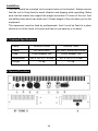
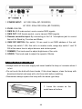
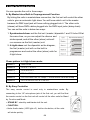
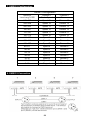
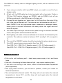
BF-1500ND B BF-750ND B BF-1500ND B BF-750ND B User Guide Professional Entertainment Technology TABLE OF CONTENTS 1. Introduction 2. Safety Precaution 3. Technical Specifications 4. General Functions 5. How To Change The Lamp 6. How To Control the Unit A. By Master/Slave Built In Preprogrammed Function B. By Easy Controller C. By universal DMX Controller 7. DMX512 Configuration 8. DMX512 Connection 9. Troubleshooting 10. Fixture Cleaning 1A 1. Introduction Congratulations on the purchase of your new strobe light. We are confident you will enjoy many trouble free hours with this unit. To assist with the care and use of the product we have prepared this short guide. 2. Safety Precaution • Avoid direct eye exposure. • Disconnect from mains power before replacing lamp or servicing. • Always replace the lamp with same type. • To prevent fire or shock hazard, do not expose this unit to rain or moisture. • Do not use this product continuously longer than 15 minutes under maximum speed and dimmer. The following points are important for safety as well as for the smooth installation and performance of the unit. • Unpack carefully and be sure that no damage has occurred during transportation. • It is very important to ground the yellow/green conductor in order to meet safety regulations. • Do not connect the device to any dimmer pack. • The electrical work that is necessary for installation must be done by qualified personnel. • Be sure to locate the unit in a place with adequate ventilation at least 15 cm from the walls. Be sure that no ventilation slots are blocked. • Be careful that no liquids or other objects can enter into the unit. If this ever happens, disconnect the main power immediately. • In the event of serious operating problems, turn off the power immediately. Never try to repair the unit by yourself. Repairs carried out by non-qualified personnel can lead to serious damage or malfunction. Please contact your dealer for technical assistance. Always use genuine spare parts. • Always remember to unplug the unit from the mains power before any service is done. 2A Installation The unit should be mounted via its screw holes on the bracket. Always ensure that the unit is firmly fixed to avoid vibration and slipping while operating. Make sure that the bracer can support the weight more than 10 times of the unit. And use safety chain which can hold over 12 times weight of the unit when you fix the equipment. The equipment must be fixed by professionals. And it must be fixed at a place where is out of the touch of human and has no one pass by or sit down. 3. Technical Specifications Lamp XENON 1500W XENON 750W Power AC 230V 50Hz AC 230V- 50Hz/120V-60Hz Fuse Circuit breaker 20A Circuit breaker 15A 452 x 147.5 x 116 mm 307 x 147.5 x 116 mm 3.2 kg 2.7 kg Dimensions Weight 4. General Functions 3A 1. POWER INPUT: AC 230V 50Hz (BF-1500ND B) AC 230V- 50Hz/120V-60Hz (BF-750ND B) 2. FUSE: 20A/15A 3. DMX IN: XLR male socket, use to receive DMX signals. 4. DMX OUT: XLR female socket, use to transmit DMX signals. 5. Remote controller input: By connecting to the 1/4 “microphone jack to control the unit for Stand by, Function and Mode. 6. DMX DIP SWITCH: Dip switch 1-9 are used to set DMX address of the unit. Assign dip switch 1 ON, this unit is in master mode, assign dip switch 1 and 10 ON at the same time to adjust dimmer and strobe speed. 7. DIMMER: This knob used to adjust brightness of the units. 8. SPEED: This knob used to adjust the speed of Strobe. 5. How To Change The Lamp • Always switch off the main supply and never handle the lamp or luminaire when it is hot. • Do not touch the bulb with bare hands. If this does happen, clean the lamp with denatured alcohol and wipe with a lint free cloth before installing. • Remember always replace the lamp with the same type lamp. 1. Loose the screws on the metal base at bottom. 4A 2. Open the glass base-cover. 3. Loose the screws of the lamp wire from terminator. 4. Take out the old lamp and replace the new one to the fixture. 5. Connect the lamp wire to the terminator. 6. Reverse the procedures from step 2 to step 1. 5A 6. How To Control the Unit You can operate the unit in three ways: A. By Master/slave Built-in Preprogrammed Function By linking the units in master/slave connection, the first unit will control the other units to give an automatic light show. You will know which unit is the master because its DMX input jack will have nothing plugged into it. The other units (slaves) will have DMX cables plugged into the DMX input jacks (daisy chain). You can set the units in below two ways: 1. Synchronized show: set the first unit(master)dipswitch 1 and 10 to be ON at the same time, so you can adjust the dimmer and strobe speed, and all the other (slave) units will run as same as the first (master) unit. 2. 4-Light show: set the dipswitch as the diagram, the first (master) unit will run the built-in programmer and control the other (slave) units for 4-light show. Chase pattern in 4-light show mode: Pattern 1 1234 Full on Pattern 2 1-2-3-4 ― 4-3-2-1 Pattern 3 1-2-3-4-4-3-2-1 Pattern 4 12-34 ― 23-14 Pattern 5 1-12-123-1234-123-12-1-stop ― 4-43-432-4321-432-43-4-stop Pattern 6 1-2-1-2-3-4-3-4―4-1-4-1-3-2-3-2 B. By Easy Controller The easy remote control is used only in master/slave mode. By connecting to the 1/4” microphone jack of the first unit, you will find that the remote control on the first unit will control all the other units for Stand by, Function and Mode. -- STAND BY : stand by and blackout all the unit. -- FUNCTION : • Under Audio status ( LED light off ), hold on the button, all the units will strobe quickly. 6A • Under Manual status ( LED light on ), press the button for choosing next pattern, triggered by music. • Under Auto status ( LED light blinking ), press the button briefly to choose the patterns ( 6 patterns varied with different speeds: fast, normal, or slow ). Hold on the button to choose the 6 patterns varied with 3 different brightness. -- MODE: • AUDIO status ( LED light off ): All patterns triggered by music. • MANUAL status ( LED light on ): Press button Function to choose the next pattern triggered by music. • AUTO status ( LED light blinking ): Press button Function briefly for speed selection; hold on the Function button for brightness selection. C. By universal DMX controller If you use a universal DMX controller to control the units, you have to set dip switches from 1 to 9 of the channel so that all the units will receive its DMX signal. Please refer to the following diagram to know how to address your DMX512 system in the binary code. DMX512 Address Chart Dip #1 #2 #3 #4 #5 #6 #7 #8 #9 #10 Value 1 2 4 8 16 32 64 128 256 Option • Examples: Channel 1 : dip / on : #1 ( =1 ) Channel 3 : dip / on : #1, #2 ( 1 + 2 = 3) Channel 5 : dip / on : #1, #3 ( 1 + 4 = 5 ) Channel 7 : dip / on : #1, #2, #3 ( 1 + 2 + 4 = 7 ) 7A 7. DMX512 Configuration DMX512 configuration DMX512 Level rang 0~255 Channel 1 Channel 2 Strobe Speed Dimmer 240~255 Speed 15 Dimmer 15 224~239 Speed 14 Dimmer 14 208~223 Speed 13 Dimmer 13 192~207 Speed 12 Dimmer 12 176~191 Speed 11 Dimmer 11 160~175 Speed 10 Dimmer 10 144~159 Speed 9 Dimmer 9 128~143 Speed 8 Dimmer 8 112~127 Speed 7 Dimmer 7 96~111 Speed 6 Dimmer 6 80~95 Speed 5 Dimmer 5 64~79 Speed 4 Dimmer 4 48~63 Speed 3 Dimmer 3 32~47 Speed 2 Dimmer 2 16~31 Speed 1 Dimmer 1 0~15 Stopped Blackout 8. DMX512 Connection 8A The DMX512 is widely used in intelligent lighting control, with a maximum of 512 channels. 1. If you using a controller with 5 pins DMX output, you need to use a 5 to 3 pin adapter-cable. 2. At last unit, the DMX cable has to be terminated with a terminator. Solder a 120 ohm 1/4W resistor between pin 2(DMX-) and pin 3(DMX+) into a 3-pin XLR-plug and plug it in the DMX-output of the last unit. 3. Connect the unit together in a ‘daisy chain’ by XLR plug from the output of the unit to the input of the next unit. The cable can not be branched or split to a ‘Y’ cable. DMX512 is a very high-speed signal. Inadequate or damaged cables, solder joints or corroded connectors can easily distort the signal and shut down the system. 4. The DMX output and input connectors are pass-through to maintain the DMX circuit, when power is disconnected to the unit. 5. Each lighting unit needs to have an address set to receive the data sent by the controller. The address number is between 0-511 (usually 0 & 1 are equal to 1). 6. The end of the DMX512 system should be terminated to reduce signal errors. 7. 3 pin XLR connectors are more popular than 5 pin XLR. 3 pin XLR: Pin 1: GND, Pin 2: Negative signal (-), Pin 3: Positive signal (+) 5 pin XLR: Pin 1: GND, Pin 2: Negative signal (-), Pin 3: Positive signal (+) 9. Troubleshooting • If the unit is not functioning well – check main power supply is ‘on’ and check fuses. • If the unit is functioning but lamp does not light - may require replacing lamp. • If the unit is not moving to the music, check the sound-activation adjustment (when applicable) • After trying these solutions, you still have a problem, contact your dealer for technical assistance. • The unit has built-in thermal switch. The lamp will not work when the internal temperature is above 80℃, and the lamp will work again when the internal temperature is cool down. 9A ※ Caution • Do not obstruct the air vents. • Do not touch the unit while it’s hot. • No user serviceable parts inside, please refer to the nearest authorized technical assistance office for service 10. Fixture Cleaning The cleaning of internal and external optical lenses and/or mirrors must be carried out periodically to optimize light output. Cleaning frequency depends on the environment in which the fixture operates: damp, smoky or particularly dirty surrounding can cause greater accumulation of dirt on the unit’s optics. Clean with soft cloth using normal glass cleaning fluid. Always dry the parts carefully. Clean the external optics at least every 20 days. Clean the internal optics at least every 30/60 days. 10A EC Declaration of Conformity We declare that our products (lighting equipments) comply with the following specification and bears CE mark in accordance with the provision of the Electromagnetic Compatibility (EMC) Directive 89/336/EEC. EN55014-2: 1997 A1:2001, EN61000-4-2: 1995; EN61000-4-3:2002; EN61000-4-4: 1995; EN61000-4-5: 1995, EN61000-4-6:1996, EN61000-4-11: 1994. & Harmonized Standard EN 60598-1: 2004 IEC 60598-1:2003+ corrigendum 2004 Part 1:General requirements and test Following the provisions of the low voltage directive 73/23/EEC and 93/68/EEC Innovation, Quality, Performance 11A