1
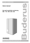
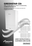
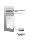
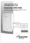
Installation and Operating Instructions
RT 10
Room temperature controller for
heating
appliances with
ROOM TEMPERATURE
CONTROLLER
bus-enabled
Heatronic 3 and TD 200
FOR WORCESTER HEATING APPLIANCES
6 720 612 218-00.1R
6 720 612 218-00.1R
WITH10
BUS-ENABLED HEATRONIC 3 AND TD 200
RT
6 720 612 218 GB (05.09) OSW
Order no. 7 719 002 505
INSTALLATION,
USER INSTRUCTIONS &
CUSTOMER CARE GUIDE
Dear customer,
Congratulations on having decided in
favour of a top-quality product from our
company.
The RT 10 offers everything you can
expect from a modern heating control:
It is both reliable and energy saving.
Like all Bosch Group products, the
RT 10 has been produced and tested
according to the most stringent quality
standards so that you can enjoy the
WORCESTER warmth for a long time
to come.
2
6 720 612 218 GB (05.09)
Contents
Contents
Safety precautions
4
4
General information
13
Symbols
4
5
Troubleshooting
14
1
1.1
1.2
1.3
1.4
Technical data for
the accessory item
Standard package
Technical data
Accessories
Description of function
5
5
5
5
6
2
2.1
2.2
Installation
Assembly
Electrical connections
7
7
9
3
3.1
Operation
10
Change required room
temperature, time limited (a) 11
3.2 Advance the next
switching time and the
associated operating
mode to the current time
(b) (Advance Heating)
11
3.3 Frost protection
12
3.3.1 Room frost protection
12
3.3.2 Frost operating mode
12
3.4 Further operation and
features
12
6 720 612 218 GB (05.09)
3
Safety precautions
Safety precautions
Symbols
B These instructions must be
observed to ensure correct operation.
Safety instructions in
this document are identified by a warning-triangle symbol and are
printed on a grey background.
B The accessories should be installed
by an authorised heating installer
only.
B Only use these accessories in conjunction with the heating appliances
listed. Observe connection diagram!
B Never connect this accessory item
to the 230 V mains electricity supply.
B Before assembling these accessories:
Interrupt voltage supply (230 V AC)
to the heating appliance and all
additional devices using the bus.
B Do not install this accessory in
damp areas.
Signal words indicate the seriousness
of the hazard in terms of the consequences of not following the safety
instructions.
•
Caution indicates that minor damage to property could result.
•
Warning indicates that minor personal injury or serious damage to
property could result.
•
Danger indicates that serious personal injury could result. In particularly serious cases, lives could be at
risk
i
Notes are identified
by the symbol shown
on the left. They are
bordered by horizontal lines above and below the text.
Notes contain important information in
cases where there is no risk of personal
injury or damage to property.
4
6 720 612 218 GB (05.09)
Technical data for the accessory item
1
1.2
Technical data
Technical data
for the accessory Dimensions
Figure 1, page 7
item
10...24 V DC
Nominal voltage
i
Only use the RT 10 in
heating systems with
bus-enabled
Heatronic 3 in the heating appliance and
TD 200.
The RT 10 allows the control of the
room temperature of an unmixed heating circuit.
1.1
bus supply
Mains supply
Controller output
Control range
15 V DC
≤ 3.5 mA
Bus
approx. 5...30˚C
in 0.5 K increments
permissible ambient temperature
0... +50 °C
Class of
protection
III
Type of
protection
IP20
Standard package
Room temperature controller RT 10
1.3
Accessories
Text display TD 200
6 720 612 218 GB (05.09)
5
Technical data for the accessory item
1.4
•
•
•
Description of function
The integrated temperature sensor
indicates the current room temperature to the TD 200. The current room temperature is shown on
the display.
If Automatic mode is active on the
TD 200, it is possible via the RT 10
to set the required room temperature restricted to a certain time
(see Chapter 3.1 on page 11)
If Automatic mode is active on the
TD 200, the next switching time
and associated operating mode
can be advanced to the current time
(Advance Heating) (see
Chapter 3.2 on page 11).
Example:
•
desired room temperature: 21 ˚C
•
current room temperature: 16 ˚C
•
Factor for room heating: 1 K in
10 minutes
To reach the desired room temperature, the heating requires 50 minutes
on account of the 5 K difference.
Therefore, the heating starts only
10 minutes after High
the programmed switching time.
Optimum Start
This function on the TD 200 can be
switched on and off and is only activated when in Automatic mode. The
RT 10 must display auto.
Optimum Start delays the heating start
after an economy phase.
To ensure that the required room temperature is reached approx. 1 hour
after the programmed switching time
High , the TD 200 calculates the
optimum time point for the heating
start.
6
6 720 612 218 GB (05.09)
Installation
2
Installation
Danger:
risk of electric shock!
3.
B Before installing
these accessories:
Interrupt voltage
supply (230 V AC)
to the heating appliance and all additional devices using
the bus.
1.
2.
2.1
Assembly
The control quality of the RT 10
depends on the installation location.
The installation location must be suitable for controlling the entire heating
system.
6 720 612 218-04.1R
Fig. 2
Remove front casing
25 mm
100 mm
0,6 m
1,0 m
85 mm
0,75 m
1,2 m
35 mm
6 720 612 218-02.1J
Fig. 1
Select installation location
6 720 612 218 GB (05.09)
7
Installation
3,5 mm
6 mm
6 mm
3,5 mm
6 720 612 218-05.1R
Fig. 3
Fasten base plate to the wall
B Make all electrical connections (see
Fig. 4).
B Replace front cover.
8
6 720 612 218 GB (05.09)
Installation
2.2
Electrical connections
B Bus connection from the RT 10 to
additional devices using the bus
(e. g. TD 200):
Use electrical cables corresponding to type H05 VV-... (NYM-I...)
minimum.
Permissible cable lengths from the
bus-enabled Heatronic 3 circuit board
to RT 10:
Cable length
≤ 80 m
Cross section
0.40 mm2
≤ 100 m
0.50 mm2
≤ 150 m
0.75 mm2
≤ 200 m
1.00 mm2
≤ 300 m
1.50 mm2
B To avoid inductive influences, separate all leads carrying low voltage
from lines of 230 V or 400 V (minimum spacing 100 mm).
B Shield the cables in the case of
external inductive influences.
This ensures that the leads are
shielded against external influences
(e.g. heavy current cables, overhead contact wires, transformer
stations, radio and television appliances, amateur radio stations,
microwave appliances etc).
Heatronic 3
TD 200
RT 10
B
B
ST 19
A F 1
2
4
B
B
6 720 612 218-03.1J
Fig. 4
Connect RT 10 to the bus-enabled Heatronic 3.
6 720 612 218 GB (05.09)
9
Operation
3
Operation
Operating elements
Symbols
Current room temperature
auto
High
6 720 612 218-01.1J
Low
a
b
Frost
auto
Fig. 5
Next switching time and
associated operating mode
= High
= Low
= Frost
advanced to the current time
Operating elements
a
b
10
Selection knob
:
Change the required room
temperature until the next
switching time of the heating
program
Button :
Advances the next switching
time and the associated
operating mode
= High
= Low
= Frost
to the current time
Automatic mode
Burner on symbol
i
Set the flow temperature controller on the
heating appliance to
the maximum inlet
temperature required.
6 720 612 218 GB (05.09)
Operation
3.1
Change required
room temperature,
time limited (a)
3.2
If the RT 10 displays auto:
B Use the selection button
to
change the required room temperature for the current operating
mode
/
/
between 5.0˚C
... 30˚C.
The required room temperature is
briefly displayed flashing in the display instead of the current room
temperature. The change to the
required room temperature remains
active until the next switching time
of the heating program. After this
the room temperature for the corresponding operating mode programmed on the TD 200 applies
again.
If the RT 10 calls for heat, the boiler
operates until the set room temperature is reached.
i
If instead of the required room temperature -- is displayed,
the room temperature
cannot be changed.
6 720 612 218 GB (05.09)
i
Advance the next
switching time and
the associated operating mode to the
current time (b)
(Advance Heating)
This function is for use
in case of unexpected
heating demands.
If the RT 10 displays Automatic mode
auto:
B Press the
button to advance the
next switching time and the associated operating mode
= High
= Low
= Frost
to the current time.
is shown on the display and the
corresponding symbol also appears
to indicate the change of operating
mode
/
/ .
i
If two lines -- are displayed instead of ,
the function is not
available.
11
Operation
3.3
Frost protection
3.3.1
Room frost protection
If the temperature in the room drops
below 5˚C, the heating is switched on.
To maintain a minimum 5˚C room temperature, the heating is switched on
and off as appropiate.
3.3.2
3.4
Further operation
and features
Additional operating options and functions are described in the TD 200 and
the boiler literature. Please refer to the
corresponding operating instructions.
Frost operating mode
The TD 200 enables the room temperature for the Frost
operating mode
to be set from 5˚C to 30˚C. With the
default setting the room temperature
for the room in which the RT 10 is
mounted is 7 °C.
12
6 720 612 218 GB (05.09)
General information
4
General information
... Notes on saving energy:
•
The temperature in the room where
the RT 10 is installed acts as a
guide parameter for the entire heating network. As a result, the power
of the radiators must be set as low
as possible, using thermostatic
radiator valves.
•
Control the temperature in the
adjoining rooms via thermostatic
radiator valves.
•
Heat from other sources in the
room (e.g. sunshine etc.) can lead
to the heating in the adjoining
rooms remaining too low.
•
A significant amount of energy can
be saved by lowering the room temperature. A reduction in temperature by 1 K (˚C) can result in up to
5 % energy saving.
•
Good thermal insulation of the
building: The set low temperature
level is not reached. Energy is
therefore saved, as the heating
remains switched off.
•
Do not keep windows open on vent
setting to ventilate. This would continuously cool down the room without significantly improving the air in
the room.
6 720 612 218 GB (05.09)
•
Ventilate fully for a short time (completely open windows).
•
Turn the thermostatic valve during
ventilation or switch to low setting.
13
Troubleshooting
5
Troubleshooting
In the event of a fault in the heating
appliance, the display will show e.g.
A7 E.
In the event of a fault in the RT 10, the
display will show e.g. 1A4 E.
Here the figure 1 stands for a fault in
the RT 10 and the letter E for Error (=
fault):
B Contact a heating expert.
Display
Cause
Remedy by an expert
1A4 E
Temperature sensor in the
RT 10 defective.
Replace RT 10.
1A8 E
TD 200 using the bus no
longer responds.
Check bus connection and, if
necessary, rectify interruption.
Heating appliance using the
bus no longer responds.
Check bus connection and, if
necessary, rectify interruption.
Error display for the heating
appliance.
Rectify the fault in accordance
with the heating appliance documentation.
e.g.:
A7 E
...
14
6 720 612 218 GB (05.09)
Troubleshooting
Complaint
Cause
Remedy
Required temperature not
reached
Thermostatic valve(s) in
the room set to low
Open the thermostatic
valve(s).
Flow temperature controller on the heating appliance set too low
Set flow temperature controller
higher.
Air lock in the heating sys- Vent radiator and heating system
tem.
Required room
temperature is
greatly
exceeded
Installation location of the
RT 10 not suitable, e.g.
outer wall, proximity to window, draught, ...
Choose a better installation
location (see Chapter 2.1) and
have the RT 10 moved by a
professional.
Excessive room
temperature
fluctuations
Temporary effect of heat
from other sources on the
room, e.g. from sunshine,
room lighting, TV, fireplace etc.
Choose a better installation
location (see Chapter 2.1) and
have the RT 10 moved by a
professional.
Temperature
rise instead of
fall
Time of day set incorrectly Check setting.
on the TD 200
Room temperature too high in
low mode
Building has high degree
of heat storage
Select low mode earlier.
Incorrect or no
control
Bus connection defective
for the devices using the
bus
Have the bus connection
checked and, if necessary, rectified by a professional according to the connection diagram.
6 720 612 218 GB (05.09)
15
INSTALLATION,
USER INSTRUCTIONS &
CUSTOMER CARE GUIDE
Worcester, Bosch Group
Cotswold Way, Warndon, Worcester WR4 9SW.
Tel. 01905 754624 Fax. 01905 754619
www.worcester-bosch.co.uk
Worcester Bosch Group is a trading name of
BBT Thermotechnology UK Ltd.
6 720 612 218 (05/09) OSW