1
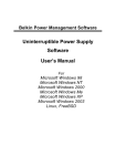
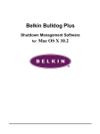
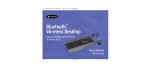
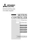
Artisan Technology Group is your source for quality
new and certified-used/pre-owned equipment
• FAST SHIPPING AND
DELIVERY
• TENS OF THOUSANDS OF
IN-STOCK ITEMS
• EQUIPMENT DEMOS
• HUNDREDS OF
MANUFACTURERS
SUPPORTED
• LEASING/MONTHLY
RENTALS
• ITAR CERTIFIED
SECURE ASSET SOLUTIONS
SERVICE CENTER REPAIRS
Experienced engineers and technicians on staff
at our full-service, in-house repair center
WE BUY USED EQUIPMENT
Sell your excess, underutilized, and idle used equipment
We also offer credit for buy-backs and trade-ins
www.artisantg.com/WeBuyEquipment
InstraView REMOTE INSPECTION
LOOKING FOR MORE INFORMATION?
Visit us on the web at www.artisantg.com for more
information on price quotations, drivers, technical
specifications, manuals, and documentation
SM
Remotely inspect equipment before purchasing with
our interactive website at www.instraview.com
Contact us: (888) 88-SOURCE | [email protected] | www.artisantg.com
Mx-RAM
User’s Manual
0102-9002A.1
Artisan Technology Group - Quality Instrumentation ... Guaranteed | (888) 88-SOURCE | www.artisantg.com
USA Headquarters
1203 New Hope Road
Raleigh, North Carolina 27610-1474
Tel.: (800)848-2330
+1-919-231-8000
Fax: +1-919-231-8001
International Sales Department
67, rue Charles-de-Gaulle
78350 Jouy-en-Josas
France
Tel.: +33 – (0) 1 39 56 72 72
Fax: +33 – (0) 1 39 56-72 70
Corporate Headquarters
150 rue Marcelin Berthelot
ZI Toulon-Est, BP 244
83078 Toulon Cedex 9
France
Tel.: +33 (0) 4 94 16 34 00
Fax: +33 (0) 4 94 16 34 01
United Kingdom
Moulton Park Business Centre
Redhouse Road • Moulton Park
Northampton • NN3 6AQ • UK
Tel.: +44 – 1604 497 791
Fax: +44 – 1604 497 792
Checkout our web site at www.thalescomputers.com
UNI/RT, UNI/XT and POWERENGINE are registered trademarks of Thales Computers – Micro Channel, AIXwindows, PowerPC,
RISC System/6000 and IBM are registered trademarks of IBM Corp. – UNIX is a registered trademark licensed exclusively by
X/Open Company Limited – All other product names, trademarks and registered trademarks are the property of their respective
holders.
Copyright Thales Computers 2000
Thales Computers reserves the right to make changes to any products herein without further notice. Thales Computers makes no warranty,
representation or guarantee regarding the suitability of its products for any particular purpose, nor does Thales Computers assume any liability
arising from the application or use of any product or circuit, and specifically disclaims any and all liability, including without limitation
consequential or incidental damages. “Typical” parameters can and do vary in different applications. All operating parameters including
“Typicals” must be validated for each customer application by customer’s technical experts. Thales Computers does not convey any license under
its patent rights nor the rights of others. Thales Computers’ products are not designed, intended, or authorized for use as components in systems
intended for surgical implant into the body, or other applications intended to support or sustain life, or for any other application in which the failure
of the Thales Computers product could create a situation where personal injury or death may occur. Should Buyer purchase or use Thales
Computers products for any such unintended or unauthorized application, Buyer shall indemnify and hold Thales Computers and its officers,
employees, subsidiaries, affiliates, and distributors harmless against all claims, costs, damages, and expenses, and reasonable attorney fees arising
out of, directly or indirectly, any claim of personal injury or death associated with such unintended or unauthorized use, even if such claim alleges
that Thales Computers was negligent regarding the design or manufacture of the part.
Restricted Rights Legend
Use, duplication, or disclosure by the contractor or the Government is subject to restrictions as set forth in subdivision (b)(3)(ii) of the
rights in Technical Data and Computer software clause 52.227-7013.
No part of this document may be reproduced, stored in a retrieval system, transcribed, or transmitted in any form, or by any means
without prior explicit permission from Thales Computers.
Your comments on this manual will be welcome.
A sheet is appended for you to submit your remarks.
Artisan Technology Group - Quality Instrumentation ... Guaranteed | (888) 88-SOURCE | www.artisantg.com
TABLE OF CONTENTS
LIST OF FIGURES.................................................................................... ii
LIST OF TABLES...................................................................................... ii
Chapter one INTRODUCTION ......................................................one-1
1.1 Manual Overview................................................................................ one-1
1.2 Product Overview ............................................................................... one-1
Chapter two INSTALLATION....................................................... two-1
2.1 Precautions ........................................................................................... two-1
2.2 Default Settings.................................................................................... two-1
2.3 Installing the Memory Devices.......................................................... two-2
2.4 Setting the Jumpers ............................................................................. two-5
2.5 Installing the Board ............................................................................. two-6
Chapter three .................................................................................. three-1
MEMORY ADDRESSING............................................................. three-1
3.1 Memory Map .....................................................................................three-1
3.2 Data Transfers....................................................................................three-2
Chapter four......................................................................................four-1
POWER MONITOR .........................................................................four-1
4.1 Battery Status ...................................................................................... four-1
Appendix A SPECIFICATIONS.....................................................four-1
A.1 VMEbus Compliance ........................................................................ four-1
A.2 Addressing/Data Transfer Capabilities......................................... four-1
A.3 AC Electrical Characteristics............................................................ four-1
A.4 Power Requirements......................................................................... four-2
A.5 Environmental Limits ....................................................................... four-2
i
Artisan Technology Group - Quality Instrumentation ... Guaranteed | (888) 88-SOURCE | www.artisantg.com
LIST OF FIGURES
1-1. Mx-RAM Standard Configurations................................................................ one-1
1-2. Mx-RAM Functional Diagram ........................................................................ one-2
2-1. Memory Device Layout ...................................................................................two-3
2-2. Jumper Locations..............................................................................................two-4
2-3. Address Mode Select........................................................................................two-5
2-4. Memory Size Select ..........................................................................................two-5
2-5. Write Protect Select ..........................................................................................two-5
2-6. Base Address Select..........................................................................................two-6
4-1. Mx-RAM Front Panel ...................................................................................... four-1
A-1. Mx-RAM Timing Diagram ............................................................................ four-1
LIST OF TABLES
2-1. Factory Default Jumper Settings.....................................................................two-1
2-2. Mx-RAM SRAM and EEPROM Specifications .............................................two-2
3-1. Mx-RAM Memory Map .................................................................................three-1
A-1. Timing Parameters ......................................................................................... four-1
A-2. Mx-RAM Power Requirements .................................................................... four-2
A-3. Mx-RAM Environmental Limits................................................................... four-2
ii
Artisan Technology Group - Quality Instrumentation ... Guaranteed | (888) 88-SOURCE | www.artisantg.com
Chapter one
INTRODUCTION
1.1
Manual Overview
This manual describes the operation of the MD-RAM, MX-RAM, and MRRAM VMEbus memory boards from Thales Computers. Chapter Two guides
the installation process. Chapter Three discusses memory access. Chapter
Four describes the power monitor. Appendix A contains board specifications.
Appendix B provides parts layouts for the three board configurations.
Throughout this manual the term “Mx-RAM” (with the lower case “x” as a
place holder) will be used if the information applies to all of the three
functionally related boards.
For additional information on VMEbus architecture, refer to the VMEbus
specification. A copy of this specification can be obtained from:
IEEE Service Center
Order Department
445 Hoes Lane
Piscataway, NJ 08854-4150
1-800-678-4333
1.2
Product Overview
VITA
10229 N. Scottsdale Road
Suite B
Scottsdale, AZ 85253
1-602-951-8866
The Mx-RAM provides up to four megabytes of battery-backed, nonvolatile,
static random access memory (SRAM) in a double-height (6U) form factor.
Available configurations are shown in Figure 1-1. The MD-RAM is intended
Mx-RA M- xx
Standard Temperature (0 to 70°C)
Extended Temperature (-40 to 85°C)
Rugged, Extended Temperature (-40 to 85°C)
D
X
R
Memory Options
No SRAM (MD- and MX- versions only)
512 KBytes SRAM
1 MByte SRAM
2 MBytes SRAM
4 MBytes SRAM
NN
25
21
32
34
Figure 1-1. Mx-RAM Standard Configurations.
Thales Computers
MD-, MX-, MR-RAM User’s Manual
Artisan Technology Group - Quality Instrumentation ... Guaranteed | (888) 88-SOURCE | www.artisantg.com
Page 1-1
for use under normal environmental conditions. The MX-RAM can operate
over an extended temperature range. The MR-RAM is designed for both
extended temperatures and rugged environments. Figure 1-1 also indicates
that the MD- and MX-RAM boards are available without memory devices
installed. This option allows for on-site user installation of EEPROM devices
instead of SRAM. For additional details on board capabilities, refer to
Appendix A. Major features of the Mx-RAM include:
•
•
•
•
•
•
Up to 4 Mbytes of nonvolatile memory.
Factory installed and tested SRAM devices or unpopulated.
128 K x 8, 32-pin or 32 K x 8, 28-pin devices.
Low-power consumption.
Battery-backed memory for years of data retention.
Extended operating temperature versions for -40° to 85°C.
The major functions of the Mx-RAM are shown in Figure 1-2. Mx-RAM memory is organized as two banks of 32-bit memory quads. Each bank has its own
battery and power monitor for long-term reliability. Battery status indicators
enhance maintainability. Data retention is conservatively rated at ten years
Memory
Bank 1
SRAM (or User-Installed EEPROM)
Bank 2
SRAM (or User-Installed EEPROM)
Address
Control
Data
Power
Monitor
Status
LEDs
Address
Battery
VMEbus
Figure 1-2. Mx-RAM Functional Diagram.
for factory installed SRAM versions (at 25°C, 50% duty cycle). Front panel
status display and test switches provide a simple maintenance test and
display for battery verification. Through the use of CMOS technology, the
Mx-RAM consumes a minimal amount of power. This increases system
reliability while limiting power supply requirements.
Page 1-2
MD-, MX-, MR-RAM User’s Manual
Thales Computers
Artisan Technology Group - Quality Instrumentation ... Guaranteed | (888) 88-SOURCE | www.artisantg.com
Chapter two
INSTALLATION
2.1
Precautions
Many of the components on the Mx-RAM can be damaged by electrostatic discharges. For this reason, keep the board in its protective antistatic bag until it is
ready to be configured and/or installed. During installation, and whenever the
board is removed from the bag, it is important to follow proper procedures for
static protection. The Mx-RAM is factory-configured to operate in most systems
without further adjustment. If a particular application requires modification to
any of the jumpers, those modifications should be done at an antistatic workstation that includes an operator wrist strap and grounded bench mat. When
working with the Mx-RAM, take all necessary precautions for electronic products
that may be damaged by electrostatic discharge.
Save the antistatic bag for storing the board and for the possibility of later shipping the board.
Closely inspect the board for any signs of shipment-related damages such as
loose components or bent pins. If any evidence of damage is discovered, notify
the carrier and Thales Computers immediately.
2.2
Default Settings
The Mx-RAM is factory-configured and ready for use as received (or upon installation of any user-installed memory devices). However, jumper blocks have
been provided to allow modification of certain Mx-RAM parameters. These parameters, and the factory default jumper settings, are shown in Table 2-1.
Table 2-1. Factory Default Jumper Settings
Parameter
ADDRESS MODE
BASE ADDRESS
MEMORY DEVICE SIZE
WRITE PROTECT
Factory Default
Jumper
Block
Extended (A32)
J2
$04000000
J4
Depends on model
J6
Off
J7
These settings can be changed to accommodate user requirements. Section 2.4
details the options available.
Thales Computers
MD-, MX-, MR-RAM User’s Manual
Artisan Technology Group - Quality Instrumentation ... Guaranteed | (888) 88-SOURCE | www.artisantg.com
Page 2-1
2.3
Installing
the Memory Devices
Mx-RAM memory is configured in two banks of four memory quads. Each quad
consists of four memory devices. Figure 2-1 shows the locations of the memory
banks, quads, and devices. Either one or both memory banks may be populated.
Within a bank, one or more quads will be populated. If a quad is to be
populated, it must have all four devices installed.
The Mx-RAM boards may be populated with either 28-pin (32K x 8) or 32-pin
(128K x 8), 150 nanosecond (ns) SRAMs or, for MD-RAM and MX-RAM boards
only, user-installed EEPROM devices. All memory devices on the board, however, must be of the same size and type. 28-pin memory devices are installed
such that pins 1 and 28 of the device are inserted into pins 3 and 30 of the socket
respectively.
For the MR-RAM, memory devices are factory-soldered directly into the board
and jumper posts are wire-wrapped as required. MD-RAM and MX-RAM
boards may be ordered with memory devices installed and tested or unpopulated for on-site memory installation.
A suitable SRAM for the Mx-RAM is the OKI MSM51256, a 32K x 8 device. Use
of devices that do not meet the backup current specifications will degrade the
data retention time. Board design requires that the installed SRAMs meet the
specifications listed in Table 2-2.
EEPROM devices are allowed only in MD-RAM and MX-RAM boards specifically built for EEPROMs. These EEPROMs may be 32K x 8 devices only. Board
design requires that the installed EEPROMs meet the specifications listed in
Table 2-2.
Table 2-2. Mx-RAM SRAM and EEPROM Specifications
Parameter
SRAM
Access Delay
150 ns or faster
Active Current
70 mA or less, 100% duty cycle
30 mA or less, 1 µs cycle time
Standby Current
3 mA or less
Backup Current
10 µA or less at Ta = +85°C (MX and MR)
10 µA or less at Ta = +70°C (MD)
1 µA or less at Ta = +60°C
0.5 µA or less at Ta ≤ +25°C
Operating Temperature
0° to +70°C (MD-RAM)
-40° to +85°C (MX- and MR-RAM)
Page 2-2
MD-, MX-, MR-RAM User’s Manual
EEPROM
150 ns or faster
0° to +70°C (MD-RAM)
-40° to +85°C (MX-RAM)
Thales Computers
Artisan Technology Group - Quality Instrumentation ... Guaranteed | (888) 88-SOURCE | www.artisantg.com
LSB
LSB
LSB
LMB
LMB
Q
U
A
D
Q
U
A
D
UMB
5
MSB
MSB
MSB
UMB
LSB
QUAD 4
LMB
UMB
QUAD 3
LMB
LSB
LMB
Q
U
A
D
LSB
Q
U
A
D
LMB
BANK 0
UMB
2
MSB
MSB UMB LMB LSB -
B1
LSB
Q
U
A
D
0
MSB
B2
LSB
1
UMB
BANK 1
7
UMB
MSB
LMB
UMB
6
MSB
LMB
Q
U
A
D
UMB
MSB
Most Significant Byte
Upper Middle Byte
Lower Middle Byte
Least Significant Byte
Figure 2-1. Memory Device Layout.
Thales Computers
MD-, MX-, MR-RAM User’s Manual
Artisan Technology Group - Quality Instrumentation ... Guaranteed | (888) 88-SOURCE | www.artisantg.com
Page 2-3
J7
WRITE
INHIBIT
J6
MEMORY
SIZE
(1 MB or 4 MB)
J3
J1
J2
J5
ADDRESS
MODE
(A24 or A32)
J4
ADDRESS
SELECT
NOTES:
1. ■ INDICATES PIN 1.
2. FOR J4 ADDRESS SELECT: JUMPER IN = 0, JUMPER OUT = 1.
3. JUMPERS J1, J3, AND J5 FOR FACTORY USE ONLY.
Figure 2-2. Jumper Locations.
Page 2-4
MD-, MX-, MR-RAM User’s Manual
Thales Computers
Artisan Technology Group - Quality Instrumentation ... Guaranteed | (888) 88-SOURCE | www.artisantg.com
In addition to installing memory devices, the user may also modify the operation
of the Mx-RAM by setting certain jumpers. Jumper block locations are shown in
Figure 2-2. Table 2-1 shows the factory default settings.
2.4
Setting the
Jumpers
J2 ADDRESS MODE
1
1
A32
A24
Install jumpers in J2 as shown in Figure 2-3 to enable
the VMEbus standard address (A24) mode or extended address (A32) mode. In standard mode the
board responds to a 24-bit address and ignores the
settings for address bits A31..A24. In extended mode
all 32 bits of the address are used. A32 address mode
is the factory default setting.
Figure 2-3. Address Mode Select.
J6 MEMORY SIZE
1
1
32K x 8
DEVICES
128K x 8
DEVICES
Jumper block J6 is used to set the size of the memory
devices installed in the Mx-RAM. The options are
shown in Figure 2-4. With the jumpers set for 32K x 8
(28-pin) devices, the board address granularity is 1
Mbyte. With the jumpers set for 128K x 8 (32-pin)
devices, the address granularity is 4 Mbytes. The default setting is configuration-dependent.
Figure 2-4. Memory Size Select.
J7 WRITE PROTECT
WRITE PROTECT ON
WRITE PROTECT OFF
Figure 2-5. Write Protect Select.
Jumper block J7 controls the write protect option as
shown in Figure 2-5. No jumper installed (default)
permits memory writes to the Mx-RAM in the VMEbus non-privileged space. Install a jumper to protect
memory and inhibit writes to the board in the nonprivileged address space. If write protection is on, a
bus error will be generated when non-privileged
writes are attempted.
Jumper block J4 is used to set the Mx-RAM base address as shown in Figure 2-6.
For the A24 address mode, only one address digit must be set. The others are
ignored. For the A32 mode, all three digits must be considered. The factory default setting (A32 mode) is $04000000. Ensure selected addresses comply with
Note 2 of Figure 2-6.
Thales Computers
MD-, MX-, MR-RAM User’s Manual
Artisan Technology Group - Quality Instrumentation ... Guaranteed | (888) 88-SOURCE | www.artisantg.com
Page 2-5
J4 BASE ADDRESS SELECT
A24 EXAMPLE: C
ACTUAL ADDRESS
IS 00C00000
FOR A24
ADDRESSING
FOR EACH DIGIT: JUMPER IN = 0, JUMPER OUT = 1
DON'T
CARE
DON'T
CARE
0000 = 0
DON'T
CARE
0001 = 1
0010 = 2
0011 = 3
1ST
DIGIT
C
0100 = 4
0101 = 5
0110 = 6
0111 = 7
A32 EXAMPLE: 51C
ACTUAL ADDRESS
IS 51C00000
FOR A32
ADDRESSING
1000 = 8
1001 = 9
1010 = A
1011 = B
1ST
DIGIT
2ND
DIGIT
3RD
DIGIT
DON'T
CARE
5
1100 = C
1101 = D
1110 = E
1111 = F
1
C
NOTES:
1. n INDICATES PIN 1.
2. FOR 4 MBYTE BOARD LAST DIGIT MUST BE 0, 4, 8, OR C.
Figure 2-6. Base Address Select.
2.5
Installing the Board
Page 2-6
The Mx-RAM may be installed in any slot of the VMEbus system. The board
jumpers the VMEbus daisy chains with traces in the printed circuit board. No
other preparation is required.
MD-, MX-, MR-RAM User’s Manual
Thales Computers
Artisan Technology Group - Quality Instrumentation ... Guaranteed | (888) 88-SOURCE | www.artisantg.com
Chapter three
MEMORY ADDRESSING
3.1
Memory Map
The memory map for an Mx-RAM populated with 32K x 8 SRAMs (1 Mbyte total
capacity) and an Mx-RAM populated with 128K x 8 SRAMs (4 Mbyte total
capacity) is shown in Table 3-1. The map also applies to 32K x 8 EEPROM
devices. The base address is set by J4 in the VMEbus A32 or A24 space. The
mapping of the memory quads is shown in the table as an offset from this base
address. Data read from an unpopulated quad is indeterminate, and data
written to an unpopulated quad is ignored.
Table 3-1. Mx-RAM Memory Map
Thales Computers
Address Offset
(32K x 8 Devices)
Address Offset
(128K x 8 Devices)
Memory
Quad
0 0000
to
1 FFFF
00 0000
to
07 FFFF
0
2 0000
to
3 FFFF
08 0000
to
0F FFFF
1
4 0000
to
5 FFFF
10 0000
to
17 FFFF
2
6 0000
to
7 FFFF
18 0000
to
1F FFFF
3
8 0000
to
9 FFFF
20 0000
to
27 FFFF
4
A 0000
to
B FFFF
28 0000
to
2F FFFF
5
C 0000
to
D FFFF
30 0000
to
37 FFFF
6
E 0000
to
F FFFF
38 0000
to
3F FFFF
7
MD-, MX-, MR-RAM User’s Manual
Artisan Technology Group - Quality Instrumentation ... Guaranteed | (888) 88-SOURCE | www.artisantg.com
Page 3-1
3.2
Data
Transfers
Page 3-2
Data may be transferred between a master and the Mx-RAM (a VMEbus slave)
with a width up to 32 bits. The data may be aligned or misaligned and follows
the conventions for a D32 VMEbus board. The write protect feature may be
inhibited by installing jumper J7.
MD-, MX-, MR-RAM User’s Manual
Thales Computers
Artisan Technology Group - Quality Instrumentation ... Guaranteed | (888) 88-SOURCE | www.artisantg.com
Chapter four
POWER MONITOR
4.1
Battery Status
Two 750 mAH lithium batteries provide battery backup
power for the memory banks. Data retention is conservatively rated at ten years for factory installed SRAM at
25°C and fifty percent duty cycle. Battery B1 powers
quads zero through three. Battery B2 powers quads four
through seven unless those quads are configured for
EEPROMs, in which case B2 and its associated circuitry
are not installed on the board.
When VCC drops below 4.75 V, the power monitor inhibits accesses to all memory quads (an access that was in
progress is allowed to complete before inhibiting that
quad) and places the SRAMs in the data retention mode.
When VCC drops below the battery voltage, the power
monitor switches the SRAM power to the batteries.
BATTERY 2
STATUS
FAIL
PASS
On power up, when VCC exceeds the battery voltage, the
power monitor switches the SRAM power to VCC. When
VCC exceeds 4.75 V, the power monitor places the
memory quads into the standby state. Two hundred
milliseconds after VCC exceeds 4.75 V, the power monitor
enables accesses to the SRAMs.
FAIL
PASS
STATUS
BATTERY 1
Battery status may be checked whenever the system
power is applied by looking at the front panel battery
status lights. Figure 4-1 illustrates the front panel with
indicator lights. If the battery voltage is above 2.0 V, the
green “PASS” light will illuminate. If the battery voltage
is below 2.0 V, the red “FAIL” light will illuminate. Each
battery has its own pair of status lights. For self-test, all
lights illuminate whenever the VMEbus SYSRESET*
signal is asserted (system reset in progress).
Mx-RAM
Figure 4-1. Mx-RAM
Front Panel.
Thales Computers
MD-, MX-, MR-RAM User’s Manual
Artisan Technology Group - Quality Instrumentation ... Guaranteed | (888) 88-SOURCE | www.artisantg.com
Page 4-1
BLANK PAGE
Page 4-2
MD-, MX-, MR-RAM User’s Manual
Thales Computers
Artisan Technology Group - Quality Instrumentation ... Guaranteed | (888) 88-SOURCE | www.artisantg.com
Appendix A
SPECIFICATIONS
A.1
The Mx-RAM fully complies with the VMEbus standard:
VMEbus Compliance
ANSI/IEEE Std 1014-1987
IEEE Standard for a Versatile Backplane Bus: VMEbus
A.2
Addressing/Data
Transfer Capabilities
The addressing capabilities are SAD032 and SADO24, which include A32, A24,
and ADO (address only). The data transfer capability is SD32, which includes
D16 and D08 (both even and odd).
A.3
AC Electrical
Characteristics
The characteristics listed in Table A-1 apply over the full voltage and temperature range of the Mx-RAM. #1–3 in Table A-1 corresponds to times 1–3 in Figure
A-1. All times are in nanoseconds. Typical values shown are at 5.0 Volts, 25°C.
Table A-1. Timing Parameters
#
Description
Typical
Max
Notes
1
Access Delay – Read or Write
275 ns
340 ns
1
2
Termination Delay – Read or Write
45 ns
90 ns
2
3
Cycle
515 ns
575 ns
3
Notes:
1. DSA* low to DTACK* or BERR* low.
2. Both data strobes high to DTACK* and BERR* not driven.
3. This time applies to consecutive accesses.
DSA*
1
2
BERR*,
DTACK*
3
Figure A-1. Mx-RAM Timing Diagram.
Thales Computers
MD-, MX-, MR-RAM User’s Manual
Artisan Technology Group - Quality Instrumentation ... Guaranteed | (888) 88-SOURCE | www.artisantg.com
Page A-1
The power requirements for the Mx-RAM are shown in Table A-2.
A.4
Power
Requirements
Table A-2. Mx-RAM Power Requirements
Source
Min
Max
Units
VCC
4.87
5.25
V
0.53
A
ICC @ VCC = max, Ta = max
(no memories installed)
A.5
Environmental Limits
The Mx-RAM meets the environmental specifications listed in Table A-3.
Table A-3. Mx-RAM Environmental Limits
Operating Temperature
Storage Temperature
Shock:
One axis
Second axis
Third axis
Vibration
Relative Humidity
(non-condensing)
Note:
Page A-2
MD-RAM
MX-RAM
MR-RAM
0°C to 70°C
-40°C to 85°C
-40°C to 85°C
-40°C to 85°C
-40°C to 85°C
-40°C to 85°C
N/A
>50 Gs, 11 ms
53 Gs, 11 ms
48 Gs, 11.8 ms
N/A
N/A
Test Range: 10 to
2000 Hz, 3 Gs
First Resonant
Frequency:
125 Hz
0% to 90%
0% to 90%
0% to 90%
N/A
Shock and vibration testing were conducted by an independent laboratory.
The MR-RAM can be further characterized and certified for specific project requirements.
MD-, MX-, MR-RAM User’s Manual
Thales Computers
Artisan Technology Group - Quality Instrumentation ... Guaranteed | (888) 88-SOURCE | www.artisantg.com
Your comments on this document
Title: MD-, MX-, MR-RAM-xx USER’S MANUAL
Reference No: 0102-9002A.1
Errors Found in This Document
Suggestions for Improvements to This Document
Your comments will be promptly investigated by qualified technical personnel and action will be taken as
required.
If you require a written reply, furnish your complete mailing address below.
DATE:
NAME:
COMPANY:
ADDRESS:
Please mail this form with your remarks to:
Thales Computers
Product Documentation Technician
1203 New Hope Road
Raleigh, NC 27610-474
USA
Tel: (919) 231-8000
Artisan Technology Group - Quality Instrumentation ... Guaranteed | (888) 88-SOURCE | www.artisantg.com
Artisan Technology Group is your source for quality
new and certified-used/pre-owned equipment
• FAST SHIPPING AND
DELIVERY
• TENS OF THOUSANDS OF
IN-STOCK ITEMS
• EQUIPMENT DEMOS
• HUNDREDS OF
MANUFACTURERS
SUPPORTED
• LEASING/MONTHLY
RENTALS
• ITAR CERTIFIED
SECURE ASSET SOLUTIONS
SERVICE CENTER REPAIRS
Experienced engineers and technicians on staff
at our full-service, in-house repair center
WE BUY USED EQUIPMENT
Sell your excess, underutilized, and idle used equipment
We also offer credit for buy-backs and trade-ins
www.artisantg.com/WeBuyEquipment
InstraView REMOTE INSPECTION
LOOKING FOR MORE INFORMATION?
Visit us on the web at www.artisantg.com for more
information on price quotations, drivers, technical
specifications, manuals, and documentation
SM
Remotely inspect equipment before purchasing with
our interactive website at www.instraview.com
Contact us: (888) 88-SOURCE | [email protected] | www.artisantg.com