1
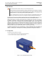
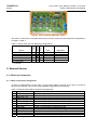
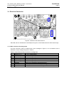
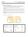
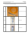
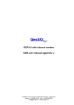
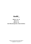
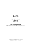
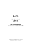
AC-63 Accelerometer
User Manual
GeoSIG Ltd, Ahornweg 5A, 5504 Othmarsingen, Switzerland
Phone: + 41 44 810 2150, Fax: + 41 44 810 2350
[email protected], www.geosig.com
GeoSIG Ltd.
GS_AC-63m_User_Manual_V09.doc / 16.03.2010
AC-63 Accelerometer User Manual
Page ii
Document Revision
Author
Checked
Approved
Serge Rudaz
Johannes Grob
Christoph Kuendig
Version
08.04.2002
18.06.2003
21.04.2004
22.11.2004
06.01.2005
21.02.2005
29.04.2005
21.06.2007
Action
Initial version, based on sensor revision 3
Version for sensor housing with single bolt mounting
Format Changes
Updated to latest production configuration
Single Ended and Current Loop specification updated
Updated for AC-63m and AC-63mi version
Small details revision
Added DH version section
Disclaimer
GeoSIG Ltd reserves the right to change the information contained in this document without notice. While the information contained
herein is assumed to be accurate, GeoSIG Ltd. assumes no responsibility for any errors or omissions.
Copyright Notice
No part of this document may be reproduced without the prior written consent of GeoSIG Ltd The software described in this document is
furnished under a license and may only be used or copied in accordance with the terms of such a license.
Trademark
All brand and product names mentioned are trademarks or registered trademarks of their respective holders.
All rights reserved.
GeoSIG Ltd
Switzerland
GS_AC-63m_User_Manual_V09.doc / 16.03.2010
AC-63 Accelerometer User Manual
GeoSIG Ltd.
Page iii
Table of Contents
Applicability of This Manual ................................................................................................ iv
Warnings and Safety .......................................................................................................... iv
Symbols and Abbreviations ................................................................................................ iv
1. Introduction...................................................................................................................... 5
1.1. Configuration ...........................................................................................................................................5
2. External Sensor ............................................................................................................... 6
2.1. Electrical Connection ..............................................................................................................................6
2.1.1. Main Connector Pin Assignment .....................................................................................................6
2.1.2. Mating Connector ............................................................................................................................7
2.2. Orientation, Mounting and Levelling .......................................................................................................7
3. Internal Sensor ................................................................................................................ 9
3.1. Electrical Connection ..............................................................................................................................9
3.1.1. Main Connector Pin Assignment .....................................................................................................9
3.2. Orientation and Levelling ......................................................................................................................10
4. Downhole Sensor .......................................................................................................... 11
4.1. Borehole preparation.............................................................................................................................11
4.2. Inclinometer tube installation.................................................................................................................12
4.3. Sensor installation.................................................................................................................................13
4.4. Inclinometer casing assembly ...............................................................................................................14
4.5. Axis orientation4....................................................................................................................................16
5. INSTALLATION VERIFICATION ................................................................................... 16
6. Maintenance .................................................................................................................. 17
GeoSIG Ltd.
GS_AC-63m_User_Manual_V09.doc / 16.03.2010
AC-63 Accelerometer User Manual
Page iv
Applicability of This Manual
a
This manual is applicable to the Sensor versions listed below:
Sensor Version
AC-63
AC-62-H
AC-62-V
AC-61-H
AC-61-V
AC-63i
AC-62-Hi
AC-62-Vi
AC-61-Hi
AC-61-Vi
Remark
external
external
external
external
external
internal
internal
internal
internal
internal
Warnings and Safety
a
STATIC ELECTRICITY
The Sensor contains electrically sensitive devices and when serviced, care must be
taken to prevent damage due to static electricity. This is very important to ensure long
term reliability of the unit.
SENSOR GROUNDING
The metallic shell of the Sensor connector should be connected to the cable shield as
well as to a potential reference. It must be connected to the local AC earthing against
potential overvoltage when a long cable is used and the associated recorder is
connected to earth.
In case of faulty AC wiring or high earth return-current, there could be high voltages
between the sensor housing and local earth potential.
A qualified electrician has to review and approve the installation in such cases.
EXPLOSIVE ATMOSPHERES
The Sensor housing provides no protection against explosive atmospheres. It must not
be directly operated in an area where explosive gases are present.
Symbols and Abbreviations
MEMS
Sensor
DAS
Micro-Electro-Mechanical Systems
AC-6x or AC-6xi
GeoSIG Data Acquisition Unit to be used with the Sensor
GS_AC-63m_User_Manual_V09.doc / 16.03.2010
AC-63 Accelerometer User Manual
GeoSIG Ltd.
Page 5
1. Introduction
a
Dear Valued GeoSIG Customer, thank you for purchasing this product.
These Instruments have been optimised to meet the requirements of the majority of customers
out of the box and may have even be delivered tailored to your needs. In any case, to be able
to get the most out of our product, please carefully study this manual, its appendices and
referenced manuals, as well as any other documents delivered with it.
This is a reliable and easy to use device, and at the same time a sophisticated product, which
requires care, attention and know-how in configuring, installing, operating and maintenance.
The AC-6x and AC-6xi are Force Balance Accelerometers using the latest MEMS sensor technology.
Uniaxial, Biaxial or Triaxial sensors are available with horizontal or vertical alignment options.
MEMS accelerometer is a miniature sensor produced in a stacked wafer construction. The sensor is
an analog force feedback accelerometer featuring a variable capacitance, silicon bulk-micromachined
acceleration sensor and a custom low-power mixed-signal integrated circuit. The custom design
results in a very low noise, low distortion sensor with high bandwidth, dynamic range, stability, and
robustness. The accelerometer can withstand shock impacts up to 1500 g’s and has a demonstrated
operating temperature range from –40 to +85 °C. The nominal bandwidth is from DC to 1.5 kHz. The
MEMS accelerometer is a small lightweight instrument capable of operating in all orientations with
more than 46 dB of cross-axis rejection and more than 120 dB of dynamic range.
To optimise the performance of the accelerometer, a custom mixed-signal ASIC was designed. As
changes in capacitance are sensed, the ASIC applies a restoring electrostatic force to keep the proofmass in a centred position. The feedback force is directly proportional to the applied acceleration.
1.1. Configuration
The AC-6x can be provided in 2 versions:
• AC-6x, external sensor with an aluminium housing (Figure 1)
• AC-6xi, internal sensor mounted in a DAS (Figure 2)
Figure 1. AC-6x, Standard External Housing
GeoSIG Ltd.
GS_AC-63m_User_Manual_V09.doc / 16.03.2010
AC-63 Accelerometer User Manual
Page 6
Figure 2. AC-6xi, Internally Mounted in a DAS
The Sensor, furthermore is available with various number of axes and axis alignment configurations,
as listed on Table 1.
Uniaxial
Biaxial
Sensor
AC-63 & AC-63i
AC-62-H & AC-62-Hi
AC-62-V & AC-62-Vi
AC-61-H & AC-61-Hi
AC-61-V & AC-61-Vi
* H: Horizontal
V: Vertical
Triaxial
Table 1. Sensor Axes and Axis Alignment Configurations
3
3
3
3
3
Axes
X–Y–Z
X–Y
X (or Y) – Z
X (or Y)
Z
Alignment*
H–H–V
H–H
H–V
H
V
2. External Sensor
2.1. Electrical Connection
2.1.1. Main Connector Pin Assignment
All AC-6x accelerometers use the same 12 pins male metallic connector as the AC-2x and AC-3x
sensors from GeoSIG. The connector pins standard assignments are as follows:
Table 2. External Sensor Main Connector Pin Assignment
Pin
Signal
Remark
1
OUTPUT X (+)
0 V ± 5 V voltage output, 47 Ω output impedance
2
OUTPUT X (-)
0 V ± 5 V voltage output inverted, 47 Ω output impedance
3
OUTPUT Y (+)
0 V ± 5 V voltage output, 47 Ω output impedance
4
OUTPUT Y (-)
0 V ± 5 V voltage output inverted, 47 Ω output impedance
5
OUTPUT Z (+)
0 V ± 5 V voltage output, 47 Ω output impedance
6
OUTPUT Z (-)
0 V ± 5 V voltage output inverted, 47 Ω output impedance
7
TEST INPUT
Test input, output will result in a sensor step response
8
GROUND
Ground, not connected to mechanical ground
9
+12 VDC power
Power input, +10 to +15 VDC range, 75 mA @ +12 VDC
10
GROUND
Ground, not connected to mechanical ground
11
AUX
Auxiliary input (reserved)
12
GROUND
Ground, not connected to mechanical ground
GeoSIG Ltd.
GS_AC-63m_User_Manual_V09.doc / 16.03.2010
AC-63 Accelerometer User Manual
Page 7
2.1.2. Mating Connector
The mating connector for the Sensor is illustrated on Figure 3 and respective part numbers are
provided in Table 3.
Table 3. AC-6x Mating Connector Part Numbers
GeoSIG
P/N #J_CIR.012.002.F
CONINVERS
P/N RC 12 S 1 N 12L 300
Binder Serie 623
P/N 99 4622 00 12
Figure 3. AC-6x Mating Connector
Cable gland nut has to be determined regarding the external diameter of the cable used and must be
separately ordered. It has also to provide the cable shield connection to the connector case.
2.2. Orientation, Mounting and Levelling
Orientation of the Sensor can be arranged within options illustrated on Figure 4, depending on the
sensor type.
TRIAXIAL FLOOR
UNIAXIAL V FLOOR
BIAXIAL H - V
BIAXIAL H - H
Y
1
2
WALL
UNIAXIAL H l l
TRIAXIAL WALL
WALL
X
X
Y
Y
WALL
BIAXIAL H - V l l
Z
WALL
Z
4
3
BIAXIAL H - V
UNIAXIAL V
Z
X
X
UNIAXIAL H
FLOOR
Z
Z
Z
FLOOR
5
WALL
BIAXIAL H - H
6
WALL
TRIAXIAL CEILING
Z
Z
X
X
X
Y
Y
7
UNIAXIAL V CEILING
8
UNIAXIAL H
CEILING
Y
9
UNIAXIAL H l l
CEILING
Y
11
10
BIAXIAL H - V
Z
CEILING
BIAXIAL H - V l l
CEILING
X
Y
Y
Y
14
15
12
BIAXIAL H - H CEILING
Z
Z
X
X
13
X
16
17
18
Figure 4. Sensor Orientation Possibilities (see Table 4)
Table 4. Sensor Orientation Details
Mounting on
Remark
Wall
Connector / Cable Inlet always towards the ground
Floor or Ceiling
Connector / Cable Inlet always at the negative X direction
The Sensor must be firmly mounted to a surface and levelled, if the application requires. Check to be
sure that the Sensor is oriented to produce the desired output signals. Acceleration in the direction
GeoSIG Ltd.
GS_AC-63m_User_Manual_V09.doc / 16.03.2010
AC-63 Accelerometer User Manual
Page 8
indicated on the housing will produce a positive output signal for that direction. The orientation
definitions as shipped are X = North, Y = West and Z = UP.
The surface should have a scribed north/south orientation line accurately surveyed from reliable
markers. The X-axis of the sensor has to be pointed to East or to any other main direction of the
structure to monitor.
Small size and single bolt mounting allow the external Sensor to be easily installed and levelled saving
installation time. The procedure to mount and level the Sensor is as follows, referring to Figure 5:
• Check that the 3 levelling screws are approximately 5 mm extending below the Sensor.
• Drill a hole for the M8 expanding nut rock anchor (supplied with the Sensor) and insert the anchor
in the drilled hole and screw-in the M8 Hex fixation screw (supplied with the Sensor) until
approximately 15 mm is left above the foundation surface (including the head).
165.0
*
.5
R1
+0.2
40.0
-0.2
-0.0
10.0
23.0
4.0
28.0
14.0
20.0
19.0
+0.1
68.0
20.3
181.5
41.0
195.0
152.0
6.0
41.0
R
6.
5
15.0
15.0
56.0
76.0
ø 15
15.0
Space Allowance for the Connector and Cable:
* Minimum
Sensor with Connector: 300 mm from sensor housing
3 x M6
99.0
16.0
Sensor with Cable Inlet: 200 mm from sensor housin
80.0
96.0
112.0
ø9
6.0
R
R
R
3.
0
0
3.
5
1.
165.0
Figure 5. Dimensions, Axis Orientation and Fixation
• Plug the larger hole at the bottom of the Sensor on the head of the fixation screw.
• Gently slide the Sensor sidewise to insert the head of the fixation screw in the extended groove.
a
Never overtighten any of the screws. There is no need to force any of the screws to a
level where it can not be tightened anymore. Doing so may damage the Sensor or the
housing considerably.
• Fix or loosen any of the 3 levelling screws to achieve the correct levelling as well as to achieve a
good fixation of the Sensor.
Optionally there can be a water bubble level provided on the sensor, to enable easier levelling.
GeoSIG Ltd.
GS_AC-63m_User_Manual_V09.doc / 16.03.2010
AC-63 Accelerometer User Manual
Page 9
3. Internal Sensor
3.1. Electrical Connection
Levelling Screws
Figure 6. Interface of the Internal Sensor
Red LED, which is outlined with a thick ellipse in Figure 6, is illuminated when the Sensor test is high.
3.1.1. Main Connector Pin Assignment
The main connector, which is outlined with a thick rectangle in Figure 6, is in accordance with to
DIN41651, with pin assignment given in Table 5.
Table 5. Internal Sensor Main Connector Pin Assignment
Pin
SIGNAL
Comment
1
OUTPUT X (+)
0 V ± 5 V voltage output
2
OUTPUT X (-)
0 V ± 5 V voltage output
3
OUTPUT Y (+)
0 V ± 5 V voltage output
4
OUTPUT Y (-)
0 V ± 5 V voltage output
5
OUTPUT Z (+)
0 V ± 5 V voltage output
6
OUTPUT Z (-)
0 V ± 5 V voltage output
7
TEST INPUT
Test input, output will result in a sensor step response
8
GROUND
Ground, not connected to mechanical ground
9
+12 VDC power
Power input, +10 to +15 VDC range, 75 mA @ +12 VDC
10
GROUND
Ground, not connected to mechanical ground
GeoSIG Ltd.
GS_AC-63m_User_Manual_V09.doc / 16.03.2010
AC-63 Accelerometer User Manual
Page 10
3.2. Orientation and Levelling
Figure 7. Internal Sensor Axis Orientation
Check to be sure that the Sensor is oriented properly to produce the desired output signals.
Acceleration in the direction indicated on the DAS housing will produce a positive output signal. The
orientation definitions as shipped are X = North, Y = West and Z = UP. Please refer to Figure 4 for
orientation possibilities, which can be achieved by mounting the DAS accordingly.
a
Please refer to the manual of your DAS for any limitations on the mounting orientation due to
the DAS features.
The internal Sensor has a single M6 center fixation screw and a 3-feet-levelling mechanism similar to
the external Sensor, but designed for mounting and levelling in a DAS. Fix or loosen any of the 3
levelling screws to achieve the correct levelling as well as to achieve a good fixation of the Sensor.
a
Never overtighten any of the screws. There is no need to force any of the screws to a
level where it can not be tightened anymore. Doing so may damage the Sensor or the
housing considerably.
Optionally there can be a water bubble level provided on the Sensor, to enable easier levelling.
GeoSIG Ltd.
GS_AC-63m_User_Manual_V09.doc / 16.03.2010
AC-63 Accelerometer User Manual
Page 11
4. Downhole Sensor
The sensor must be installed in a 3-inch inclinometer tube. At least a
100 mm borehole must be drilled. Depending on the soil condition, it
could be required to drill a higher dimension hole and to implement a
120 mm PVC casing to insure a free path when the inclinometer tube is
inserted in the borehole.
4.1. Borehole preparation
Note: Do not scale the drawing.
1
2
Depth of drilled borehole
Surface
level
PVC
tubing
Minimum free
diameter
inside casing:
120 mm.
Casing
sealing
Cap
Do not allow concrete mix from casing sealing to enter the casing.
GeoSIG Ltd.
Page 12
GS_AC-63m_User_Manual_V09.doc / 16.03.2010
AC-63 Accelerometer User Manual
4.2. Inclinometer tube installation
30 cm
3 meters
Note: Do not scale the drawing. The number of section is only an example.
Inclinometer tube
in 3 meters
section.
Sealing (concrete
mix) of tube
Coupling elements,
fixed with “pop”
rivets. Must be fully
sealed to avoid any
concrete inside the
tube.
Bottom cap.
Must be fully
sealed to avoid
any concrete
inside the tube.
GeoSIG Ltd.
GS_AC-63m_User_Manual_V09.doc / 16.03.2010
AC-63 Accelerometer User Manual
Page 13
4.3. Sensor installation
About 50 cm
Cable
The maximum
water level above
the sensor must be
maximum 50
meters.
About 70 cm
About 170 cm
50 m maximum
Note: Do not scale the drawing. The number of section is only an example.
Concrete sealing of
sensor. At least 1
meter above the
sensor.
Sensor AC-63-DH,
diameter 54 mm.
Guiding system
Sand (50 cm)
GeoSIG Ltd.
GS_AC-63m_User_Manual_V09.doc / 16.03.2010
AC-63 Accelerometer User Manual
Page 14
4.4. Inclinometer casing assembly
The borehole must have a casing or the soil must insure that a free path for the inclinometer tube is
warranted. It is recommended to insert the inclinometer tube as soon the borehole is ready.
The free path for the inclinometer tube should be 10 to 15 cm, 12 cm typically.
It could be required to insert some water in the casing to sustain the water pressure at the bottom of
the borehole.
The inclinometer tube should be mounted with a maximum deviation of ±1° / 3 meters and with a
maximum deviation from vertical at sensor location of ±3°. The functional limit for the sensor is ±9°.
The water level in the inclinometer tube should be maximum 50 meters, including fast elevation due to
heavy rain.
It is recommended to use the optional assembly kit that GeoSIG can provide (optional) with the
inclinometer tube. It will insure a perfect sealing of the tube elements and would avoid concrete mix to
enter the tube.
The dimensions of the inclinometer tube are:
INCLINOMETRIC CASING (3 m section)
COUPLING ELEMENT
A
Inner diameter
76.1 mm
A Inner diameter
81.0 mm
B
Groove outer diameter
86.4 mm
B Outer diameter
92.0 mm
C
Thickness
2.2 ±0.1 mm
C Thickness
2.2 mm
D
Groove inner diameter
82.0 mm
D Groove inner diameter
87.6 mm
Length
3 meters
Length
300 mm
Weight
1.4 Kg/m
Weight
0.5 kg
Borehole diameter
> 120 mm
GeoSIG Ltd.
GS_AC-63m_User_Manual_V09.doc / 16.03.2010
AC-63 Accelerometer User Manual
Page 15
The following elements will be inserted in the borehole.
Figure 8
Torpedo (the sensor and its cable)
Figure 9
Guiding system
Figure 10
Inclinometer tube
GeoSIG Ltd.
GS_AC-63m_User_Manual_V09.doc / 16.03.2010
AC-63 Accelerometer User Manual
Page 16
4.5. Axis orientation4
Engraved
mark
Z axis
X axis
Y axis
Figure 11, Down hole axis orientation
Before the sensor is inserted in the inclinometer tube, the guiding system must be mounted bellow it.
The guiding system must be orientated before the insertion.
The engraved mark on bottom cover is showing the positive direction of X axis:
Z axis:
Vertical,
positive up
Y axis
Mark
X axis
View for top:
5. INSTALLATION VERIFICATION
Please note that temperature compensation device is mounted for each axis inside the sensor and
that the temperature in the sensor has to stabilize before accurate measurement can be done. Allow
at least half an hour for temperature stabilization.
GS_AC-63m_User_Manual_V09.doc / 16.03.2010
AC-63 Accelerometer User Manual
GeoSIG Ltd.
Page 17
6. Maintenance
The GeoSIG AC-6x accelerometers are true servo accelerometers, which are sealed from the
environment. As such, there is no routine or additional maintenance required for the AC-6x
accelerometers unlike many competitive force balance accelerometers, which require constant
checking and adjustments to correct inherent drift problems and changing mass/spring constants. For
critical, long-term applications we recommend the periodic use of the self-test capability to verify
integrity of the system and installation. In precision applications we recommend a calibration audit
interval of 1 year.