1
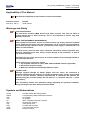
CR-5P
User Manual
GeoSIG Ltd, Ahornweg 5a , 5504 Othmarsingen, Switzerland
Phone: + 41 44 810 2150, Fax: + 41 44 810 2350
[email protected], www.geosig.com
GS_CR-5P_UserManual_V03.doc / 16.03.2010
CR-5P User Manual
Page ii
Document Revision
Author
Checked
Approved
Markus Epp
Johannes Grob
Dr. Talhan Biro
Version
10.05.2007
24.06.2007
23.07.2007
15.09.2007
29.11.2007
03.05.2008
11.03.2009
Action
Initial release [NV, RA]
Version released with the initial shipment [RA]
Manual reviewed and updated (minor editing) [ME]
Add Recorder Module CR-5PRHDx [ME]
Update connection pictures [YB]
Add Remote Data Streaming [ME]
Change of Address [STT]
Disclaimer
GeoSIG Ltd. reserves the right to change the information contained in this document without notice. While the information contained
herein is assumed to be accurate, GeoSIG Ltd. assumes no responsibility for any errors or omissions.
Copyright Notice
No part of this document may be reproduced without the prior written consent of GeoSIG Ltd. The software described in this document is
furnished under a license and may only be used or copied in accordance with the terms of such a license.
Trademark
All brand and product names mentioned are trademarks or registered trademarks of their respective holders.
All rights reserved.
GeoSIG Ltd.
Switzerland
GS_CR-5P_UserManual_V03.doc/ 16.03.2010
CR-5P User Manual
Page iii
Table of Contents
Table of Figures................................................................................................................... v
Applicability of This Manual ................................................................................................ vi
Applicability of This Manual ................................................................................................ vi
Warnings and Safety .......................................................................................................... vi
Symbols and Abbreviations ................................................................................................ vi
1. Introduction...................................................................................................................... 1
2. Incoming Inspection......................................................................................................... 2
2.1. Damage during Shipment .......................................................................................................................2
2.2. Warranty..................................................................................................................................................2
3. Description....................................................................................................................... 3
3.1. Housing ...................................................................................................................................................3
3.2. Portable A/D Module (PAD) ....................................................................................................................4
3.2.1. LED's ...............................................................................................................................................4
3.2.2. Connectors.......................................................................................................................................4
3.3. Communication Module (COM)...............................................................................................................5
3.3.1. LED's ...............................................................................................................................................5
3.3.2. Connectors.......................................................................................................................................5
3.4. Recorder Module (RHDx)........................................................................................................................6
3.4.1. LED's ...............................................................................................................................................6
3.4.2. Connectors.......................................................................................................................................7
3.5. External DC Power Supply......................................................................................................................7
3.6. Storage....................................................................................................................................................7
4. Installation ....................................................................................................................... 8
4.1. Site Selection ..........................................................................................................................................8
4.1.1. Environmental Considerations.........................................................................................................8
4.1.2. Power Supply Considerations..........................................................................................................8
4.2. Installation ...............................................................................................................................................8
4.2.1. Supply Voltage Selection.................................................................................................................9
4.2.2. Requirements for the Instrument Installation...................................................................................9
4.2.3. Mounting the Instrument ..................................................................................................................9
4.2.4. Optional Interconnection..................................................................................................................9
4.2.5. Completing the Installation ............................................................................................................10
4.3. Cabling ..................................................................................................................................................10
4.3.1. Power.............................................................................................................................................10
4.3.2. Communication..............................................................................................................................11
4.4. First Start Up .........................................................................................................................................12
4.4.1. Start Up of the COM Module .........................................................................................................12
4.4.2. Start Up of the RHDx Module ........................................................................................................13
Page iv
GS_CR-5P_UserManual_V03.doc / 16.03.2010
CR-5P User Manual
4.4.3. Start Up of the PAD Module.......................................................................................................... 14
5. Configuring Parameters Putting in Operation.................................................................16
5.1. Quick Setup .......................................................................................................................................... 16
5.1.1. Login to the RHDx module............................................................................................................ 16
5.1.2. Add new PAD Module ................................................................................................................... 18
5.1.3. Enable the Data Stream Recording .............................................................................................. 18
5.1.4. Add new COM Module .................................................................................................................. 19
5.2. Data Streaming to Remote Computer .................................................................................................. 20
5.2.1. RHDx Settings............................................................................................................................... 20
5.2.2. Remote Computer Settings........................................................................................................... 21
5.3. Data Access on the Remote Computer................................................................................................ 22
6. Advanced Network Settings ...........................................................................................24
6.1. Introduction........................................................................................................................................... 24
6.2. IP Change of the PAD or COM module................................................................................................ 24
6.3. Adjustment of the CRP Manager.......................................................................................................... 26
7. Functional Description....................................................................................................27
7.1. Signal Conditioning............................................................................................................................... 27
7.1.1. Digital Signal Filtering ................................................................................................................... 27
7.2. Triggering ............................................................................................................................................. 28
7.3. Clock..................................................................................................................................................... 28
7.3.1. GPS Option ................................................................................................................................... 28
7.3.2. Synchronisation............................................................................................................................. 28
8. Troubleshooting and Maintenance .................................................................................29
8.1.1. Power ............................................................................................................................................ 29
8.1.2. Real Time Clock RTC ................................................................................................................... 29
8.1.3. Data Streaming ............................................................................................................................. 29
8.1.4. COM module reset every couple of hours .................................................................................... 29
8.1.5. RHDx module reset every couple of hours ................................................................................... 30
8.2. Maintenance ......................................................................................................................................... 30
GS_CR-5P_UserManual_V03.doc / 16.03.2010
CR-5P User Manual
Page v
Table of Figures
Figure 1. CR-5P Housing ...................................................................................................................................3
Figure 2. CR-5P System overview using a computer as CCU (left) or a recorder module RHDx (right)...........3
Figure 3. PAD module, front view.......................................................................................................................4
Figure 4. PAD module, rear view (three or nine connectors) .............................................................................4
Figure 5. COM module, front view......................................................................................................................5
Figure 6. COM module, rear view ......................................................................................................................5
Figure 7. RHDx module, front view ....................................................................................................................6
Figure 8. RHDx module, rear view .....................................................................................................................6
Figure 9. Example of powering a CR-5P system .............................................................................................10
Figure 10. Example of networking a CR-5P system ........................................................................................11
Figure 11: IP change on the laptop ..................................................................................................................16
Figure 12: GeoDAS running inside the RHDx module .....................................................................................17
Figure 13: Watchdogs settings of the COM module ........................................................................................19
Figure 14. Disconnect from Remote Desktop Connection ...............................................................................19
Figure 15. Data forwarding over Network.........................................................................................................20
Figure 16. Network Links..................................................................................................................................21
Figure 17. Map a network drive........................................................................................................................22
Figure 18. Map of the data folder from the RHDx module ...............................................................................23
Figure 19: IP change on the laptop ..................................................................................................................24
Figure 20. Change X-Port network settings .....................................................................................................25
Figure 21. Change the IP in the CRP Manager ...............................................................................................26
Figure 22. Default settings for the internal watchdog.......................................................................................30
GS_CR-5P_UserManual_V03.doc / 16.03.2010
CR-5P User Manual
Page vi
Applicability of This Manual
a
This manual is applicable to the Firmware versions listed below:
Firmware Version
V40.00.01 and up
Remark
Initial release
Warnings and Safety
a
STATIC ELECTRICITY
The Instrument contains CMOS devices and when serviced, care must be taken to
prevent damage due to static electricity. This is very important to ensure long term
reliability of the unit.
a
INSIDE THE INSTRUMENT (MAINTENANCE)
Under normal circumstances, there is no need to remove any of the printed circuit board
covers inside the Instrument. The racks themselves can be removed and exchanged by
user without posing a threat to device, provided the power supply is switched off or all
cables are disconnected.
The rack covers, from the other hand, should be removed by trained personnel only.
Moreover untrained access may lead to serious damage to the Instrument, as well as
may void the warranty.
Especially the rack cover should never be removed without first contacting GeoSIG or
your local representative.
Before removing any of the racks, always:
1. Flip all power switches to "OFF" (PAD, COM and RHDx module if applicable)
2. Disconnect the power supply
3. Make sure that the blue On/Off LED indicator is OFF
a
BATTERY LIFE
Although supplied through an AC/DC adapter from the mains, the instrument is
optionally shipped with the batteries to provide the backup power supply. If the system
is not in use, the batteries should be disconnected. If connected, the batteries are
attached using the crocodile clamps; the red cable on "+", the black cable on “–“ poles
of the battery.
Note: The battery lifetime can drastically change depending on operating conditions.
Strong discharge of the main battery must be avoided.
Symbols and Abbreviations
CR-5P
CMOS
VDC
VAC
PC
SPS
Vpp
PAD
COM
RHDx
Portable Central Recording System
Complementary Metal Oxide Semiconductor
DC Voltage
AC Voltage
IBM© compatible Personal Computer
Samples Per Second
Volts peak to peak
Portable A/D converter
Communication module
Recorder module
GS_CR-5P_UserManual_V03.doc/ 16.03.2010
CR-5P User Manual
Page 1
1. Introduction
a
Dear Valued GeoSIG Customer, thank you for purchasing this product.
These Instruments have been optimised to meet the requirements of the majority of customers
out of the box and may have even be delivered tailored to your needs. In any case, to be able to
get the most out of our product, please carefully study this manual, its appendices and
referenced manuals, as well as any other documents delivered with it.
This is a reliable and easy to use device, and at the same time a sophisticated product, which
requires care, attention and know-how in configuring, installing, operating and maintenance.
The Portable Central Recorder (in further text CR-5P) is a 24 bit portable seismic system suitable for
centralised data acquisition and recording. The CR-5P is designed for both temporary and permanent setups
such as bridges, tunnels, and tall buildings. It is easy to use and provides user with a possibility to easily
reinstall the system and acquire the seismic data from numerous measurement points. The CR-5P nodes
can be easily interconnected to obtain a synchronised network for data acquisition from remote and distant
points.
Several types of externally mounted sensors can be used with the instrument, like seismometers,
geophones, accelerometers, anemometers or other sensors with single-ended or differential outputs.
The signals such as temperature are considered slow-changing and the chosen sampling rate might be the
minimum one (typically a few samples per second suffice). The accelerometers, on the other side, generate
the signals of a wider bandwidth and as such require higher sampling rate (typically 50 SPS or higher
depending on the required bandwidth, i.e. type of the events observed at the specific site).
The CR-5P collects and records the data, which can later be downloaded and analysed on a remote PC
running the dedicated software package GeoDAS. Recorded data include the sensor data, clock/timing
information and instrument configuration information.
Frequency response (bandwidth) depends on the chosen low-pass filter and the sampling rate. Typical
attenuation at 99% of the Nyquist frequency is >120dB.
During normal operation the instrument continuously amplifies, filters and converts sensor inputs to 24 bit
digital form and passes these to the recorder module (RHDx). The recording parameters can be set by
remote with a common laptop from anywhere inside the network. The recorded data can then be
downloaded over the network and analysed with the GeoDAS software package. Instead of the recorder
module (RHDx) an existing computer system can be used as well.
Trigger algorithms include STA/LTA ratio triggering and level triggering. The STA/LTA ratio trigger computes
the short term and long term signal averages.
A CR-5P node is comprised of one or more portable digitiser modules (PAD) and an optional communication
module (COM). The PAD module further contains up to three triaxial digitisers giving the PAD possibility to
acquire data from up to nine channels. The triaxial digitisers from each PAD are further connected via
Ethernet cable and the COM module to a recorder module (RHDx) or another computer working as central
control unit CCU.
The PAD digitisers are typically configured from the CCU itself or if using a RHDx, from a laptop anywhere in
the network. Besides configuration, this connection facilitates data acquisition and performs a complete
sensors test as well via the menu driven software GeoDAS.
a
GeoSIG continuously improves and enhances capabilities of all products. There may be several
other connectivity, hardware or software options for the Instrument, which are not covered in
this manual. Refer to separate documentation from GeoSIG about available options.
GS_CR-5P_UserManual_V03.doc/ 16.03.2010
CR-5P User Manual
Page 2
2. Incoming Inspection
All Instruments are carefully inspected both electrically and mechanically before they leave the factory.
Please check if all received items correspond to the packing list and your order confirmation. In case of
discrepancies please contact GeoSIG or your local representative immediately.
2.1. Damage during Shipment
If requested at the time of order, all instruments can be insured prior to the shipment. If you receive damaged
equipment and shipping insurance was previously arranged you should:
• Report the damage to your shipper immediately
• Inform GeoSIG or your local representative immediately
• Keep all packaging and shipping documents
a
Insurance claims may be void if the above procedure is not followed.
2.2. Warranty
GeoSIG Ltd. (hereafter GeoSIG) warrants hardware and software products against defects in materials,
workmanship and design for the defined period in the relevant contract or offer, starting from date of
shipment and 5 years parts and maintenance support commitment. If GeoSIG receives notice of such
defects during the warranty period, GeoSIG shall at its option either repair (at factory) or replace free of
charge hardware and software products that prove to be defective. If GeoSIG is unable, within a reasonable
time to repair or replace any instrument to a condition as warranted, buyer shall be entitled to a refund of the
purchase price upon return of the instrument to GeoSIG. 50 % of freight charges on shipments of warranty
repairs or replacements will be borne by GeoSIG (normally one way freight).
Limitation of Warranty:
The foregoing guarantee shall not apply to defects resulting from:
•
•
•
•
or
•
Improper or inadequate maintenance by buyer
Buyer supplied software or interfacing
Unauthorised modification or misuse
Operation and storage outside of the environmental specifications of the instrument
Improper preparation and maintenance of site.
GS_CR-5P_UserManual_V03.doc/ 16.03.2010
CR-5P User Manual
Page 3
3. Description
3.1. Housing
The CR-5P is comprised of 19” rack units (PADs and optional COM or RHDx) housed in a portable case with
handles and lids. Information regarding the instrument's date of manufacturing, serial number, etc. is
contained on the ID label on the outside of the housing.
Figure 1. CR-5P Housing
Figure 2. CR-5P System overview using a computer as CCU (left) or a recorder module RHDx (right)
GS_CR-5P_UserManual_V03.doc/ 16.03.2010
CR-5P User Manual
Page 4
3.2. Portable A/D Module (PAD)
Figure 3. PAD module, front view
Figure 4. PAD module, rear view (three or nine connectors)
3.2.1. LED's
N (Network)
These red LEDs indicate that the digitiser is transmitting the data. The LED "A" refers to the first, "B" to the
second, and "C" to the third digitiser. The digitisers transmit data at different time intervals, which is indicated
by non-simultaneous LED illumination.
Status
These green LEDs continuously illuminate as the corresponding channels are enabled. Otherwise, the LEDs
are off. The first LED from the left of the first row corresponds to the channel 1 of the digitiser "A"; the second
LED from the left of the first row corresponds to the channel 2 of the digitiser "A", and so on.
On/Off
This blue LED is continuously illuminated when the unit is switched on. Otherwise, the LED is off.
3.2.2. Connectors
The PAD has typically three connectors on the front side and five at the back. Optional configuration that
relies on the uniaxial sensor connection utilises 11 connectors on the back side.
3.2.2.1. Sync Connectors
The front side sync connectors are used for synchronisation and optional GPS connection. SYN in is used as
the synchronisation input (SYNC output of the previous unit or GPS) while SYN out is used as the
synchronisation output.
3.2.2.2. Power
The connectors on the rear left hand side are used as power input and power output. In other words, each
PAD is supplied from the previous one, the main power supply, the COM or the RHDx module. But at the
same time it provides power on its output connector for the optional cascading. Through this seven-pin
connector the PAD is supplied with 12 VDC power. Alternatively, external batteries for powering the
instrument may be connected here.
GS_CR-5P_UserManual_V03.doc/ 16.03.2010
CR-5P User Manual
Page 5
3.2.2.3. Sensor Connectors
The connectors A1, B1, and C1 respectively are triaxial connectors. The optional connectors in between
labelled as (A2, A3, B2, B3, C2, and C3) are used when each axis utilises one connection, and is available
per customer’s specific request.
The SENSOR connector is a 12 pin connector, which is used to connect external sensor(s) to the
Instrument. It carries the output signals from the sensor(s) and the test signals from the Instrument. The
SENSOR connector provides +12 VDC power to the sensor(s).
Different types of sensors with following sensor voltage output ranges are supported:
•
•
•
•
2.5 VDC ± 2.5 VDC
0 ± 10 VDC (20 Vpp)
0 ± 2.5 VDC (5 Vpp) differential
0 ± 10 VDC (2.0 Vpp) differential
3.2.2.4. Ethernet Connectors
The ETH connector is used to attach the PAD to a RHDx module or a COM module that provides the
connection path toward the CCU.
3.2.2.5.
Earthing Screw
This is a screw to be used for proper grounding of the chassis. When used, it has to be securely connected
to a reliable Earth connection.
3.3. Communication Module (COM)
Figure 5. COM module, front view
Figure 6. COM module, rear view
3.3.1. LED's
On/Off
This blue LED is continuously illuminated when the unit switched on. Otherwise, the LED is off.
3.3.2. Connectors
There are six designated ETH connectors on the front side and one ETH connector at the back side. The
number of PAD units attached to a COM module can be expanded and is available upon special request. In
that case, the back side can contain up to five more ETH connectors.
3.3.2.1. Ethernet Connectors (Front)
The centrally located ETH connector (labelled as ETH out) is a designated ETH connector for the CCU
connection (laptop, PC or RHDx). The remaining ETH connectors (ETH1 – ETH7) are used for the PAD
GS_CR-5P_UserManual_V03.doc/ 16.03.2010
CR-5P User Manual
Page 6
modules connection. There is no correlation between the physical location of the specific PAD module and
the connector relative position.
3.3.2.2. Ethernet Connector (Rear)
These connectors are used only for PADs and represent just a continued connector array of the PAD
connectors located at the front.
3.3.2.3.
Earthing Screw
This is a screw to be used for proper grounding of the chassis. It has to be securely connected to a reliable
Earth connection.
3.3.2.4. Power
The connectors on the rear on the left hand side are used as power input and power output. In other words,
each COM module provides power supply for the first PAD in the array. Through this seven-pin connector
the PAD is supplied with 12VDC power. Alternatively, external batteries for powering the instrument may be
connected here.
3.4. Recorder Module (RHDx)
The recorder module has the same functionality as the COM module but additionally the possibility to record
the data streams from all connected PAD’s to a internal hard disk drive
Figure 7. RHDx module, front view
Figure 8. RHDx module, rear view
3.4.1. LED's
On/Off
This blue LED is continuously illuminated when the unit switched on. Otherwise, the LED is off.
Status CPU
This green LED shows if the internal computer is switched on and running.
Status HDD
If the internal computer access to the hard disk drive, this green LED lights up. Therefore during normal
operation this LED should be illuminated from time to time.
GS_CR-5P_UserManual_V03.doc/ 16.03.2010
CR-5P User Manual
Page 7
3.4.2. Connectors
There are six designated ETH connectors on the front side and the power connector on the back.
3.4.2.1. Ethernet Connectors (Front)
The centrally located ETH connector (labelled as ETH out) is a designated ETH connector for the laptop,
which is used for configuration and data download. The remaining ETH connectors (ETH1 – ETH7) are used
for the PAD or COM modules connection. There is no correlation between the physical location of the
specific PAD or COM module and the connector relative position.
3.4.2.2.
Earthing Screw
This is a screw to be used for proper grounding of the chassis. It has to be securely connected to a reliable
Earth connection.
3.4.2.3. Power
The connectors on the rear on the left hand side are used as power input and power output. In other words,
each RHDx module can provide power supply for the first PAD or COM in the array. Through this seven-pin
connector the RHDx is supplied with 12 VDC power. Alternatively, external batteries for powering the
instrument may be connected here.
3.5. External DC Power Supply
An external 12 VDC power supply is connected to the POWER connector of the RHDx module. The power
is further distributed to the PAD modules by cascading the power supply cables.
3.6. Storage
When not in use, the Instrument should be stored at the room temperature in a dry location. Note that the
real time clock continues operation even when the main switch is in the OFF position. The real time clock is
maintained by a lithium battery.
GS_CR-5P_UserManual_V03.doc/ 16.03.2010
CR-5P User Manual
Page 8
4. Installation
This section lists the procedures involved in installation, configuration and operation the Instrument. The
procedures will be outlined as steps to be performed in the field or in house prior to deploying the instrument
in the field.
4.1. Site Selection
4.1.1. Environmental Considerations
The choice of an installation site for is similar in most respects to that of a regular continuous recording
seismic station.
Although the Instrument is housed in a solid case, it is certainly best if a location can be arranged for the
unit, which is free from direct sunlight, precipitation, the dangers of falling materials in the event of a severe
earthquake and the risk of tampering or vandalism if the unit is to be left unattended. Furthermore, the
installation site must not be affected by the weather condition such as ice, rain, or snow.
Additionally, the user should select a site with a provision for 115 / 230 VAC power if the unit is supplied from
batteries and will be left in place for a long period of time (more than 3 days). Although this is not necessary
for the operation of the device, it does preclude concerns about battery charging.
In case of event triggered recording, any cultural or environmental sources of noise and vibration around the
selected site should be noted, which may cause false triggers of the recording mechanism. These will have
to be considered when setting the trigger parameters within the GeoDAS software package.
4.1.2. Power Supply Considerations
The Instrument is powered from a 12 VDC external power supply or optionally from the backup battery (if
available) at the time of the power outage. A solar panel instead of a power supply can be used as well, ask
GeoSIG for more detail specifications.
• If the supply in the field is from a 115 / 230 VAC, you need to connect the VAC cable from the
external power supply to the power source only. The VAC source must consist of Phase, Neutral
and Protection Earth.
• If the supply will be exclusively from the battery, it is necessary to charge the battery sufficiently
beforehand. Make sure to have at least 24 hours of uninterrupted charging prior to leaving the
Instrument in the field. The configuration of the instrument, of course, may be performed while the
charger is connected to the Instrument.
The best approach to the deployment of the Instrument is to use the battery along with the AC/DC adapter at
the remote site. In the lab, the Instrument can be checked and configured for the correct time, trigger and
other relevant settings. It may then be carried to the remote site (with the power switch in the "OFF" position
to avoid electrical shocks) and then connected to the VAC power through the AC/DC adapter. After switching
it "ON", the Instrument runs with the pre-configured parameters. This reduces the amount of time needed to
configure in the field; an important consideration in the case of an adverse condition.
4.2. Installation
a
Many times the locations of seismic equipment are highly exposed to electrical disturbances
caused by lightning or by the industrial environment. It may sometimes be necessary to use
additional surge protectors for the equipment. Contact GeoSIG or your local representative for
more information.
GS_CR-5P_UserManual_V03.doc/ 16.03.2010
CR-5P User Manual
Page 9
4.2.1. Supply Voltage Selection
In case that the Instrument is powered from an AC/DC converter, ensure that the right voltage is selected
115 VAC / 60 Hz or 230 VAC / 50 Hz.
4.2.2. Requirements for the Instrument Installation
Since the instrument is portable and it collects the data from the remote sensors there are no special
requirements in terms of foundation and mechanical stability. Typically, the only limitation is the area
required for cable running toward the CR-5P housing and the housing itself.
Minimum surface area (footprint) and height requirements for the 4 HU CR-5P housing are as follows:
H300 × W550 × D600 mm
Please note that the height is limited by the number of rack modules in the housing thus possibly reducing
the height requirements.
4.2.3. Mounting the Instrument
The following are the typical items needed for installation:
•
•
•
•
•
•
•
•
•
Instrument (CR-5P)
Power cable with an external 12 VDC AC/DC adapter
Sync cable between the PAD modules and/or GPS module (if available)
Ethernet Cables for PAD – COM connection
Ethernet Cable for the connection to the RHDx or the central control unit
This Manual and its Appendices
Set of Tools
Laptop PC with GeoDAS installed, to check or configure the Instrument
Any accessories or peripheral equipment for the Instrument and their manuals, such as external
sensor, GPS, external modem, etc.
Typically follow these steps for a successful installation:
• The Instrument can be mounted in any convenient position at the location that complies with the
basic requirements outlined in the previous section.
• Ensure that all cables, especially the sensor cables, have enough space around the housing to be
connected to the PAD module.
• Ensure that all PADs have power and sync cables connected to it. Sync cables are cascaded from
one PAD to another. The power cables are cascaded from the COM module first then to nearest
PAD, then to the second PAD in the array and so on.
• Depending on the location it may be necessary to earth the Instrument properly. Therefore connect
the
(Earthing Screw) of the Instrument via a copper wire of minimum 1.5 mm2 to a proper earth
contact.
a
It is strongly recommended to have a proper Earthing.
4.2.4. Optional Interconnection
In case that the CR-5P nodes are to be interconnected to achieve the time synchronisation, ensure with
GeoSIG or your representative at the time of order that the cable length is sufficient for the particular
installation. This also applies to the situation when the PAD modules are remotely located in different
housing.
GS_CR-5P_UserManual_V03.doc/ 16.03.2010
CR-5P User Manual
Page 10
4.2.5. Completing the Installation
a
Fix the remaining cables, so that they may not influence the sensor signal by knocking
or vibrating at the sensor.
a
Do not leave any unpowered device connected to the Instrument.
After verifying that the physical installation is done properly, the Instrument can now be started and put in
operation as described in the following sections.
a
Do not touch the sensors and leave the installation site as quietly as possible.
4.3. Cabling
4.3.1. Power
The first module of each node is powered by battery and/or an external power supply, connected to 230
VAC. The power supply works as a battery charger at the same time and therefore guarantees maximum of
autonomy in case of a power loss. A solar panel instead of a power supply can be used as well, ask GeoSIG
for more detail specifications. Each module is powered by a connection to the power connector 12V in at the
rear side of the module. The subsequent module will be powered by connecting its 12V in to the power
connector labelled as 12V out of the previous module.
PAD
PAD
PAD
PAD
COM
PAD
RHDx
Power supply
115/230 VAC
Battery
Battery
PAD
PAD
Power supply
115/230 VAC
Figure 9. Example of powering a CR-5P system
GS_CR-5P_UserManual_V03.doc/ 16.03.2010
CR-5P User Manual
Page 11
4.3.2. Communication
For full functionality of the CR-5P system, all PAD modules must be synchronised. This is done by
connecting the SYN in connector on the front side of each module either to a GPS, or to the SYN out of the
previous PAD.
The PAD with a connected GPS works as a timing master; all modules connected to its SYN out have
exactly the same time, even if the GPS fails.
The measured data will be streamed by each PAD either to the RHDx module, or to another PC in the
network, working as CCU. Therefore each PAD must be connected by a Ethernet LAN cable (via COM
module) to the RHDx or CCU computer.
GPS
GPS
PAD
PAD
PAD
PAD
RHDx
PAD
COM
Ethernet Cable
(max 100 m)
Synchronisation
Expansion Cable
(max 1’000 m)
GPS Cable
(max 70 m)
PAD
PAD
Figure 10. Example of networking a CR-5P system
Every module has it IP. The IP is written on the front label and by default the IP’s are organised as can be
seen below:
Out of factory, the IP’s are 192.168.10.xxx
The xxx is…
011 … 020
for RHDx modules
021 … 030
reserved for the watchdogs inside the RHDx modules
031 … 050
for COM modules
051 … 127
for PAD modules
For any change in the network topology see chapter 0.
GS_CR-5P_UserManual_V03.doc/ 16.03.2010
CR-5P User Manual
Page 12
4.4. First Start Up
4.4.1. Start Up of the COM Module
Follow the procedure below for every start up of the module. The white boxes are ACTIONS the user has to
do; the grey boxes are DECISIONS, which affect the further process.
Connect the battery and the AC power cable to the external power supply (only if installed)
Connect the power cable to the 12V in connector.
Flip the main switch on the front to its ON position
Is the blue LED on the front continuously illuminating?
No
What is the type of the power source?
Power supply (plus battery)
No
Yes
Battery only
Is the power switch at position ON?
Yes
Yes
Switch
on
Is the power switch illuminating red
No
Disconnect the AC power cable from the power
supply
Is the fuse of the external power supply blown?
Yes
No
Replace it with a
1A slow blow
fuse
Check if the AC power is
present
No
Connect
AC power
Yes
Check cabling and battery
voltage
Found any wrong cabling?
Yes
No
Correct
cabling
Start from the beginning
Call GeoSIG
Continue
GS_CR-5P_UserManual_V03.doc/ 16.03.2010
CR-5P User Manual
Page 13
4.4.2. Start Up of the RHDx Module
Follow the procedure below for every start up of the module. The white boxes are ACTIONS the user has to
do; the grey boxes are DECISIONS, which affect the further process.
Connect the battery and the AC power cable to the external power supply (only if installed)
Connect the power cable to the 12V in connector.
Flip the main switch on the front to its ON position
Is the blue LED on the front continuously illuminating?
No
What is the type of the power source?
Power supply (plus battery)
No
Battery only
Yes
CPU LED illuminating
green?
No
Yes
Is the power switch at position ON?
Yes
Yes
Switch
on
Is the power switch illuminating red
No
Disconnect the AC power cable from the
power supply
Is the fuse of the external power supply
blown?
Yes
No
Replace it with a
1A slow blow fuse
Check if the AC power
is present
No
Yes
Connect
AC power
Check cabling and battery
voltage
Found any wrong cabling?
Yes
No
Correct
cabling
Start from the beginning
Call GeoSIG
Continue
GS_CR-5P_UserManual_V03.doc/ 16.03.2010
CR-5P User Manual
Page 14
4.4.3. Start Up of the PAD Module
Each PAD module can either be powered by another PAD module, or by a power supply and/or battery. For
the start up of the module please select the according procedure 4.4.3.1 or 4.4.3.2.
4.4.3.1. PAD is powered from the 12V out connector of another PAD, COM or RHDx module
Connect the power cable from the 12V out of another PAD, COM or RHDx to the 12V in connector.
Flip the main switch on the front to its ON position
Is the blue LED on the front continuously illuminating?
No
Are all other PAD, COM and RHDx modules powered?
(blue LEDs on the front are continuously illuminating)
No
Yes
Yes
Are all STAUS LED illuminating
green? (After a few seconds)
No
Yes
Switch on other
modules
Check cabling and battery voltage
Found any wrong cabling?
Yes
No
Correct cabling
Start from the beginning
Call GeoSIG
Continue
4.4.3.2. PAD is powered by an external power supply and/or battery
Connect the battery and the AC power cable to the external power supply (only if installed)
Connect the power cable to the 12V in connector.
Flip the main switch on the front to its ON position
Is the blue LED on the front continuously illuminating?
No
What is the type of the power source?
Power supply (plus battery)
No
Battery only
Is the power switch at position ON?
Yes
Yes
Switch
on
Is the power switch illuminating red
No
Disconnect the AC power cable from the
power supply
Is the fuse of the external power supply
blown?
Yes
No
Yes
Are all STAUS LED
illuminating green?
(After a few seconds)
No
Yes
GS_CR-5P_UserManual_V03.doc/ 16.03.2010
CR-5P User Manual
Page 15
Is the fuse of the external power supply
blown?
Yes
No
Replace it with a
1A slow blow fuse
Check if the AC power
is present
No
Yes
Connect
AC power
Check cabling and battery
voltage
Found any wrong cabling?
Yes
No
Start from the beginning
Call GeoSIG
Continue
You can now configure the operation parameters, start data acquisition or leave the Instrument for operation
with the actual configuration as described in the following sections.
GS_CR-5P_UserManual_V03.doc/ 16.03.2010
CR-5P User Manual
Page 16
5. Configuring Parameters Putting in Operation
For configuration and data acquisition a PC running GeoDAS has to be used.
a
For the installation and usage of GeoDAS refer to the GeoDAS Manual, which explains the use
of the software in full details.
The typical procedure to be followed is to connect the Ethernet cable from the PC to the COM module of the
Instrument and follow the steps described in the GeoDAS Manual to configure or perform following functions:
•
•
•
•
•
Communication with the Instrument.
Verifying the operation of the Instrument and its sensor via Analog Signals.
Setting Date and Time (if GPS is no available).
Saving and/or Loading Configuration.
Setting Recording parameters.
5.1. Quick Setup
Perform the following steps to have a basic running system within a few minutes. Make sure that all modules
are properly working and interconnected as described in chapter 4. Basic knowledge of Windows XP and
GeoDAS are assumed.
5.1.1. Login to the RHDx module
This step is only needed if using a RHDx module for data acquisition. Skip this step if you are using a
computer with GeoDAS as a CCU.
•
Connect a laptop to the ETH out of the RHDx. Use a standard Ethernet cable.
•
Set the IP of the laptop to 192.168.10.1, Subnet mask 255.255.255.0
o
Start Æ Settings Æ Network Connections
o
Double-click Local Area Connections Æ Properties Æ Internet Protocol (TCP/IP)
o
Press OK
Figure 11: IP change on the laptop
GS_CR-5P_UserManual_V03.doc/ 16.03.2010
CR-5P User Manual
•
Page 17
Open Remote Desktop
o
Start Æ Programs Æ Accessories Æ Communications Æ Remote Desktop Connection
o
Computer:
192.168.10.xx
o
User name:
CR5PRHDx
o
Password:
login003
o
Then click Connect
*1
Now you are working on the PC inside the RHDx module. The GeoDAS window appears.
Figure 12: GeoDAS running inside the RHDx module
a
*1
Don’t change any settings without proper study of the manual. Wrong handling can
result in a malfunction of the whole system.
The xx stands for any number from 11 to 20. Please look at the label of the RHDx module and type the
correct IP address
GS_CR-5P_UserManual_V03.doc/ 16.03.2010
CR-5P User Manual
Page 18
5.1.2. Add new PAD Module
•
Open in the tab GeoDAS Settings Æ Channels of Digitisers…
*1
o
Name:
xxx
o
Type:
GeoSIG D183 Digitizer
o
Press Add/Modify
o
Local COM or USB Port:
COMxxx
o
Sampling Rate:
200
o
Baudrate:
115’200
o
Time Source
External SYNC Signal
o
Select proper Full Scale and Unit
o
Press Add/Modify
o
Press OK
*2
*3
Now the data stream of the selected PAD appears in the window Stations: DataStream.
A blue arrow
next to the channel shows, that data packets are received with no errors
5.1.3. Enable the Data Stream Recording
•
*1
Open in the GeoDAS the tab Settings Æ Data Streams…
o
Keep all active streams of data (…):
o
Maximum length of data chunk (…):
30 minutes
o
Delete oldest data if disk free (…):
1000 MByte
o
Remove data files older than:
168 hours
o
Press OK
o
Restart GeoDAS
The xxx stands for any arbitrary 3-character name of the desired PAD module.
*2
The xxx stands for any number between 051 and 127 and correlates to the last three digits of the IP of the
PAD, which is written on the front side of the PAD module (e.g. 192.168.10.115 Æ COM115)
*3
The Full Scale settings depends on the sensor type, please check manual for details.
GS_CR-5P_UserManual_V03.doc/ 16.03.2010
CR-5P User Manual
Page 19
5.1.4. Add new COM Module
For the supervision all COM modules must be added to the GeoDAS too, otherwise the COM modules will
restart a couple of times per day.
•
Open in the GeoDAS the tab Settings Æ Watchdogs…
*1
o
Name:
xxx
o
Port:
COMxx
o
Baud rate:
115200
o
Press Add Watchdog
o
Change all values as seen in Figure 13
o
Press Apply
o
Press Save and Exit
*2
Figure 13: Watchdogs settings of the COM module
a
There is already a watchdog with the name RHD configured. Do not delete or change this
watchdog! Otherwise the RHDx module will restart couple of times per day.
5.1.4.1. Disconnect from RHDx Module
After the setup, the laptop can be disconnected
•
Move the mouse to the upper end of the screen and press the X
Figure 14. Disconnect from Remote Desktop Connection
*1
*2
The xxx stands for any arbitrary 3-character name of the desired COM module.
The xx stands for any number between 31 and 50 and correlates to the last three digits of the IP of the
COM, which is written on the front side of the COM module (e.g. 192.168.10.45 Æ COM45)
GS_CR-5P_UserManual_V03.doc/ 16.03.2010
CR-5P User Manual
Page 20
5.2. Data Streaming to Remote Computer
5.2.1. RHDx Settings
The following settings must be done on the RHDx module after login over Remote Desktop
•
Open GeoDAS
•
Click Settings Æ Network Links…
•
Put in the following data on the left side of the window (see
o
Enable network links with the remote applications:
Enabled
o
Network name:
Workstation
o
IP Address:
Default
o
Accept request from the remote clients at port:
Enabled, 1024
o
Support functions of a remote node:
Enabled:
•
Click OK
•
Restart GeoDAS
Figure 15. Data forwarding over Network
- Real time data streaming
- Remote configuration
GS_CR-5P_UserManual_V03.doc/ 16.03.2010
CR-5P User Manual
Page 21
5.2.2. Remote Computer Settings
The following settings must be done on the computer, where you want to receive the data streams
•
Open GeoDAS
•
Click Settings Æ Network Links…
•
Put in the following data (see Figure 16)
o
Enable network links with the remote applications:
Enabled
o
Local settings of this application, Network name:
Workstation
o
Local settings of this application, IP Address:
Default
o
Remote application, Network name:
CR-5P
o
Remote application, IP Adress:
192.168.10.xx* 1
o
Remote application, Connect through the port:
1024
o
Remote application, Connection timeout, sec:
40
o
Remote application, Inactivity timeout, sec:
600
o
Remote application, Remote node
Enabled:
o
Permanent monitoring:
Enabled
•
Click Add, then OK
•
Restart GeoDAS
- Real time data streaming
- Remote configuration
Figure 16. Network Links
*1 The xx stands for any number from 11 to 20. Please look at the label of the RHDx module and type the
correct IP address
GS_CR-5P_UserManual_V03.doc/ 16.03.2010
CR-5P User Manual
Page 22
• In the window Remote Nodes and Applications a new station CR5P appears.
• In the window Stations: Data Streams the network CR5P will all channels appears
• For display of the streams make a right-click on the cannel and press Data Monitor
For more details see GeoDAS User Manual
5.3. Data Access on the Remote Computer
The following steps must be done on the computer, where you normally download and analyse the data.
•
Open Windows Explorer
•
Click Tools Æ Map Network Drive…
Figure 17. Map a network drive
GS_CR-5P_UserManual_V03.doc/ 16.03.2010
CR-5P User Manual
•
Map the drive to the Folder: \\192.168.10.xx\GeoDAS_DATA
Page 23
*1
Figure 18. Map of the data folder from the RHDx module
•
Click Finish
•
A new drive appears under My Computer
From now on all data can be easily copied from this new drive. No login to the RHDx module is needed.
*1
The xx stands for any number between 10 and 49 and correlates to the last two digits of the IP of the
RHDx, which is written on the front side of the RHDx module (e.g. 192.168.10.16 Æ COM16)
GS_CR-5P_UserManual_V03.doc/ 16.03.2010
CR-5P User Manual
Page 24
6. Advanced Network Settings
6.1. Introduction
The CPR Manager on the RHDx module or the CCU computer creates a virtual Com-port.
a
All modules are preconfigured for easy and convenient handling and operation. A
change in the network topology needs a structured action and good knowledge in
networking
There are different modules, which must be adjusted in case of a change of the network topology.
Name
X-Port
CPR Manager
Location
PAD / COM
RHDx or CCU computer
GeoDAS
RHDx or CCU computer
Description
The X-Port is the interface from the module to the LAN
The CPR Manager redirects the virtual Com-port to the
correct IP (of the PAD or COM)
Data acquisition. For this, the correct Com- ports must be
selected.
A change in one of these three places always affects the two others.
6.2. IP Change of the PAD or COM module
•
Set the IP of the laptop in the same range as all the other modules (by factory default use IP
192.168.10.1 and Subnet mask 255.255.255.0 for the laptop)
o
Start Æ Settings Æ Network Connections
o
Double-click Local Area Connections Æ Properties Æ Internet Protocol (TCP/IP)
o
Press OK
Figure 19: IP change on the laptop
•
•
Connect a laptop the PAD either …
o
… directly by connecting a Ethernet cross-cable from the laptop to the ETH connector on the
PAD
o
… over the network, by connecting the laptop to a COM or PAD module using a standard
Ethernet cable.
Open a standard web browser as Internet Explorer or Firefox
GS_CR-5P_UserManual_V03.doc/ 16.03.2010
CR-5P User Manual
Page 25
•
As Address type // and the IP address of the PAD (e.g. //192.168.10.105), then press Enter
•
As soon as the login windows appears, press Enter (Blank Username and Password, both are not
set by default)
Figure 20. Change X-Port network settings
•
Click Network and adjust your settings
•
Press OK
•
Click Apply Settings
•
Close Browser
a
Never change any settings in the tab Channel 1
For more detail documentation, please see: http://www.lantronix.com/pdf/XPort_UG.pdf
GS_CR-5P_UserManual_V03.doc/ 16.03.2010
CR-5P User Manual
Page 26
6.3. Adjustment of the CRP Manager
With the CRP Manager the virtual Com ports on the computer can be linked to the desired IP address of the
X-Port inside the PAD or COM module
•
•
•
•
•
Open CPR Manager: Start Æ Programs Æ Lantronix Æ CPR 4.1 Æ CPR Manager
Click on the COM port on the left side you want to use.
Change the IP setting
Click OK
Click Com Port Æ Save Settings
Figure 21. Change the IP in the CRP Manager
For more detail documentation, please see: http://www.lantronix.com/pdf/Com-Port-Redirector_QS.pdf
GS_CR-5P_UserManual_V03.doc/ 16.03.2010
CR-5P User Manual
Page 27
7. Functional Description
This section discusses some of the technical details of how the Instrument works. Input signal filtering,
digitising, and time accounting are among the functions described.
7.1. Signal Conditioning
Electrical signals from seismic sensors connected to the Instrument are range-adjusted in preparation for
conversion to digital form and are filtered to prevent aliasing effects. The signals are next sampled and
digitised, and then digitally filtered under software control to further reduce noise. Then these data are used
for triggering and recording within the GeoDAS software package.
The Instrument accepts signals from sensors within the sensor voltage output ranges as follows:
•
•
•
•
2.5 VDC ± 2.5 VDC
0 ± 10 VDC (20 Vpp)
0 ± 2.5 VDC (5 Vpp) differential
0 ± 10 VDC (2.0 Vpp) differential
The Digital Values (DV) for Analog Input Voltages (AIV) are summarised in the following tables:
Table 1. DV and AIV for CR-5P Instruments
Analog Input Voltage AIV
Digital Value DV
[V]
[Bit]
0.0
-(223 – 1) x 90% = -7549746
Minimum input
2.5
0
Zero input
5.0
223 x 90% = 7549746
Maximum input
In CR-5P Instruments each signal channel has a low-pass 120 Hz 4th-order Butterworth analog filter with the
attenuation of 48dB at 500Hz. The sensor input signal passes through this filter prior to being sampled and
converted to digital form. This filter removes signal energy at frequencies above one-half the input sampling
rate (1000 Hz) so that these higher frequencies are not aliased by the sampling process. The signal level
above 400 Hz at the output of the analog filter is at least 120 dB below the input level. For different sampling
rates, anti-aliasing is achieved by the software means (equi-ripple FIR filter structures with the linear phase)
with a -3dB point above 80% of the Nyquist rate.
7.1.1. Digital Signal Filtering
The anti-aliasing low-pass filter is automatically applied by the sigma-delta A/D converter based on the
selected data output rate.
The amplified and filtered analog signals are sampled at a rate of 1000 SPS per channel and converted by a
delt-sigma AD converter to 24 Bit digital data values. Since the Instrument allows recording with output
sample rates of 50, 100, 200, and 250 SPS the data has to be further decimated digitally.
a
The sampling rate is common to all three channels digitised by one digitiser, i.e. the sampling
rate cannot be individually set for a specific channel.
A
Please note that the selectable sampling rate is available from the firmware revision 1 and up.
The digitised data still contains signal energy at frequencies of up to 500 Hz, which has to be filtered digitally
for all sample rates except 1000 SPS. At the Nyquist frequency (half the decimated sample rate) the signal is
at least 120 dB below the input level due the combined effect of the 120 Hz analog filter and the digital filter.
GS_CR-5P_UserManual_V03.doc/ 16.03.2010
CR-5P User Manual
Page 28
Since data are digitised and stored in the 24 Bit resolution, signals above the Nyquist frequency, even fullscale signals, do not affect the final stored data values at all.
7.2. Triggering
The CR-5P Instrument does not have any data storage capability. It acts as a digitiser by simply forwarding
the data to the remote host. The recording itself is performed by the GeoDAS software package on the PC
side. For more information about the possibility of triggering or to record the data, please consult the
GeoDAS manual.
7.3. Clock
The Instrument has a complete, self-contained time-keeping system. This clock keeps track of days, hours,
minutes and seconds. The instrument has the ability to set the clock to the current time manually, or to set
the time and synchronise the clock automatically with an encoded external time signal. The clock operates
from the internal battery and runs regardless whether the Main Switch is at ON or OFF position.
7.3.1. GPS Option
The GPS (Global Positioning System) is originally used for navigation. It contains several satellites, which
orbit the earth in a distance of about 20 000 km. The signals transmitted by the satellites are used to get the
position; minimum 4 satellites have to be received by the GPS receiver to find its exact position. The
transmitted signals contain also precise time information, which is used to update the internal clock of the
Instrument.
7.3.2. Synchronisation
Beside the GPS, the PADs can be synchronised with another PAD or the CCU. The CR-5P nodes have to
be interconnected with the sync cable to provide the time synchronisation. The most accurate method is to
connect a GPS module to every node. In case that there is limited sky visibility, at least one unit should be
equipped with a GPS module and the other units can be consequently synchronised by the node having the
GPS module attached to it.
When the relative accuracy and synchronisation are not of a primary interest or if the sky visibility is poor
throughout the entire installation site, all nodes can be individually synchronised (remotely from a CCU, one
by one). This type of synchronisation provides the lowest accuracy.
a
Please note that the selectable sampling rate is available from the firmware revision 1 and up.
GS_CR-5P_UserManual_V03.doc/ 16.03.2010
CR-5P User Manual
Page 29
8. Troubleshooting and Maintenance
This section describes troubleshooting procedures using the self-testing features of the Instrument if
configured via GeoDAS and the maintenance needed to be done.
8.1.1. Power
In case that the ON/OFF LED is not lit the probable cause of it is one of the following:
• The cable connection to the mains. Check that 12VDC is available on the output of AC/DC
converter.
• Ensure that the main switch in the COM module is ON. The PAD modules are sequentially
supplied from their own COM module within a node.
• Check that the fuse in the COM module is not blown.
8.1.2. Real Time Clock RTC
In case that the reported time does not correspond to the real time, the probable cause of this is one of the
following:
• The GPS module is not attached. Check if GPS is connected and functioning properly. Ensure that
there is reasonable sky visibility for clear satellites signal reception.
• The node being synchronised by another node is not attached. Check the Sync cable connection.
• In case that the problem is not resolved using the previous methods please consult the GeoSIG or
you representative.
8.1.3. Data Streaming
In case that there is no data available on the PC:
• Check that GeoDAS is configured properly. Please consult the GeoDAS manual for further
details.
• Ensure that the Ethernet cable (Labelled as ‘ETH Out’ on the COM module) is plugged in and
connected to the PC.
• Ensure that all PAD modules are properly connected to their own COM modules with the
Ethernet cables and that all PAD modules are powered on.
• If the previous methods do not resolve the problem try replacing the connection cables.
• For further troubleshooting please consult GeoSIG or your representative.
8.1.4. COM module reset every couple of hours
• Check that the COM module is connected to the RHDx module, or the computer working as
CCU.
• Check that the watchdog of the COM module is add in the GeoDAS of the RHDx module or the
CCU computer (see chapter 5.1.4)
GS_CR-5P_UserManual_V03.doc/ 16.03.2010
CR-5P User Manual
Page 30
8.1.5. RHDx module reset every couple of hours
• Login to the CR-5PRHDx over Remote Desktop and click Settings Æ Watchdogs… in GeoDAS
• Check if the Watchdog RHD has the settings as shown in Figure 22. Default settings for the
internal watchdog. If the watchdog RHD is not present, add it.
Figure 22. Default settings for the internal watchdog
8.2. Maintenance
The Instrument has been designed in a way that it requires a minimum of maintenance. If the following
procedures are performed frequently, the instrument will last for many years:
• The periodic test indicates any irregularity as soon as it occurs. Therefore it is recommended, to
check the recorded sensor test at least once a year. Compare the signals of the 3 channels with
older records. There should not be a distinctive change.
• The function of a sensor with DC response (capacitive, piezo-resistive and FB sensors) can be
checked by inclining the sensor in every axis. An inclination of 90° causes an acceleration of 1.0 g,
30° an acceleration of 0.5 g and 14.7° an acceleration of 0.25 g. Check this value for every
channel. This check should be performed annually.
• The function of the sensor can be checked frequently with a tilt table. For testing the sensor has to
be installed onto the tilt table. The whole range of ± 1g has to be checked with the table. Every axis
shall be performed. The output signal has to be compared with the calibration values given by the
manufacturer.
A sensor without AC response needs to be checked by using a shaking table. The period of this
check depends on the used sensor type. For detailed information refer to the data sheet of your
sensor.
• The voltage of the optional battery and the charging voltage of the charger shall be measured
annually. Disconnect the AC power to measure the battery voltage, keep the Instrument switched
on. The voltage should be between 11.8 and 13.2 VDC, depending on its charge. Reconnect the
AC power cable, switch off the Instrument and disconnect the battery, measure the voltage on the
battery cables. The voltage should be 13.8 ± 0.3 VDC.
• The physical condition of the Instrument and the sensor should be checked annually. Make sure
every cable and connector is in good condition and plugged in properly.
• The optional battery should be replaced every 3 years. After replacement, adjust the date of
installation and the date of the next replacement into the Instrument via GeoDAS.
• The backup battery should be replaced every 5 years. After replacement, adjust the date of
installation and the date of the next replacement into the Instrument via GeoDAS.