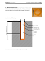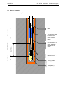
1
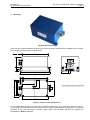
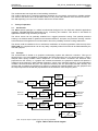
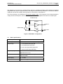
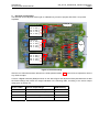
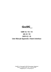
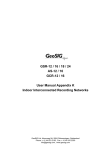
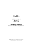
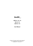
GeoSIG Ltd
AC-23 Accelerometer Manual
GS_AC-23_UserManual_V08.doc/18.03.2011
Page 1
AC-23 Accelerometer
User Manual
Author:
GeoSIG Ltd
Ahornweg 5A, 5504 Othmarsingen, Switzerland,
Tel: +41 44 810 21 50, Fax: +41 44 810 23 50, E-mail: [email protected]
Serge Rudaz
Checked:
Lukas Gätzi
Approved:
Johannes Grob
Distribution:
GeoSIG Ltd (1), Customer on request
Company:
GeoSIG Ltd
AC-23 Accelerometer Manual
GS_AC-23_UserManual_V08.doc/18.03.2011
Page 2
DOCUMENT REVISION
Date
15.04.95
11.04.00
05.07.01
Version
0
1
2
Author
SR
JG
SR
Checked
JP
GCO
JG
30.05.2003
06.06.2003
3
4
LG
LG
JG
JG
05.12.2003
21.04.2004
05.05.2006
12.12.2007
5
5
6
7
SR
JG
SR
TB
JG
JG
JG
TB
13.12.2007
18.03.2011
8
8
TB
THL
TB
TAB
Description
Created
Format/Font changes
Update pictures and connector description for new
12 poles version.
Added principle of operation.
Changes for new housing
Corrected axis polarity for new housing. Movement
in axis-direction gives positive response.
Updated
Reformatted
Adapted to new DH housing
Adapted to new sensor housing
File name and title change
Detailed sensor full scale & offset adjustment
Board connector pinning added
GeoSIG Ltd
AC-23 Accelerometer Manual
GS_AC-23_UserManual_V08.doc/18.03.2011
Page 3
TABLE OF CONTENT
1
ELECTRICAL CONNECTION ............................................................................................................. 4
1.1 MAIN CONNECTOR PIN ASSIGNMENT ................................................................................................... 4
1.2 MATING CONNECTOR ......................................................................................................................... 4
2
MOUNTING......................................................................................................................................... 5
3
THEORY OF OPERATION.................................................................................................................. 6
3.1 INTRODUCTION .................................................................................................................................. 6
3.2 PRINCIPLE ........................................................................................................................................ 6
3.3 BASIC SPECIFICATIONS ....................................................................................................................... 7
4
ELECTRICAL CONFIGURATION ....................................................................................................... 8
5
MOUNTING (DOWNHOLE SENSOR) ................................................................................................. 9
5.1 BOREHOLE PREPARATION ................................................................................................................... 9
5.2 INCLINOMETER TUBE INSTALLATION.................................................................................................... 10
5.3 SENSOR INSTALLATION ..................................................................................................................... 11
5.4 INCLINOMETER CASING ASSEMBLY ..................................................................................................... 12
5.5 AXIS ORIENTATION ........................................................................................................................... 14
6
INSTALLATION VERIFICATION....................................................................................................... 14
The sensor housing provides no protection against explosive atmosphere. It must not be directly operated in
area where explosive gases are present.
GeoSIG Ltd
AC-23 Accelerometer Manual
1
GS_AC-23_UserManual_V08.doc/18.03.2011
Page 4
Electrical Connection
1.1 Main Connector Pin Assignment
All the AC-2X accelerometers use the same 12 pins male metallic style connector as the AC-43 and AC-63.
The connector pins standard assignments are as follows:
Pin
SIGNAL
Comment
Color
1
OUTPUT X (+)
0 V ± 5 V voltage output, 47 Ω output impedance
White
2
OUTPUT X (-)
0 V ± 5 V voltage output inverted, 47 Ω output impedance
Brown
3
OUTPUT Y (+)
0 V ± 5 V voltage output, 47 Ω output impedance
Green
4
OUTPUT Y (-)
0 V ± 5 V voltage output inverted, 47 Ω output impedance
Yellow
5
OUTPUT Z (+)
0 V ± 5 V voltage output, 47 Ω output impedance
Grey
6
OUTPUT Z (-)
0 V ± 5 V voltage output inverted, 47 Ω output impedance
Pink
7
TEST INPUT
Test input, output will result in a sensor step response
Blue
8
GROUND
Ground, not connected to mechanical ground
Red
9
+12 VDC power
Power input, +10 to +15 VDC range, 50 mA @ +12 VDC
Black
10
GROUND
Ground, not connected to mechanical ground
Violet
11
AUX
Auxiliary input (reserved)
-
12
GROUND
Ground, not connected to mechanical ground
Table 1 AC-2X Connector Pin Assignment
-
In case no connector is mounted at the cable end (like usually for down-hole version), the color code is given
in the above table.
1.2
Mating connector
GeoSIG
P/N #J_CIR.012.002.F
CONINVERS
P/N RC 12 S 1 N 12L 300
Binder Serie 623
P/N 99 4622 00 12
Figure 1, Mating connector
Cable gland nut has to be determined as per cable external diameter and must be separately ordered. It has
also to provide the cable shield connection to connector case.
GeoSIG Ltd
AC-23 Accelerometer Manual
2
GS_AC-23_UserManual_V08.doc/18.03.2011
Page 5
Mounting
Figure 2, AC-2X housing
Small size and single bolt attachment allow the AC-2X to be easily installed saving installation time. Leveling
is accomplished via three point leveling screws.
165.0
*
.5
R1
+0.2
40.0
-0.2
4.0
-0.0
10.0
23.0
28.0
14.0
20.0
19.0
+0.1
68.0
20.3
181.5
41.0
195.0
152.0
6.0
41.0
R
6.
5
15.0
15.0
56.0
76.0
ø 15
15.0
Space Allowance for the Connector and Cable:
* Minimum
Sensor with Connector: 300 mm from sensor housing
3 x M6
99.0
16.0
Sensor with Cable Inlet: 200 mm from sensor housin
80.0
96.0
112.0
ø9
6.0
R
R
3.
0
0
3.
5
1.
R
165.0
Figure 3, Sensor housing dimensions
The accelerometers must be firmly mounted to a surface and leveled, as the application requires. Check to
be sure that the accelerometer is aligned to produce the desired output signals. Acceleration in the direction
indicated on the case will produce a positive output signal. The orientation definitions as shipped are:
X = North, Y = West and Z = UP.
GeoSIG Ltd
AC-23 Accelerometer Manual
GS_AC-23_UserManual_V08.doc/18.03.2011
Page 6
The accelerometer has single-bolt, 3-feet-levelling mechanism.
The surface should have a scribed north/south orientation line accurately surveyed from reliable markers.
The X-axis of the sensor has to be pointed to East or to any other main direction of the structure to monitor.
One M8 expanding nut rock anchor must be used for the sensor fixation.
3
Theory of operation
3.1 Introduction
The AC-23 sensor package is a triaxial accelerometer designed for free field and industrial applications
regarding STRONG-MOTION earthquake survey, monitoring and research. This sensor is well suited for
applications where a high sensitivity is required.
The AC-23 sensor can be optionally installed into a rugged protective housing. This optional protective
housing is in stainless steel for optimal environmental resistance. As option, the protective housing could be
executed with an IP68 grade for Free field location where the possibility exists of housing submersion.
The sensor could be installed on floor or wall with a modification of the axis organization. With the help of the
TEST LINE, the complete sensor can be very easily completely tested. Full scale can be field selected by the
user with jumpers.
3.2 Principle
The accelerometer is based on a geophone mass-spring system with electronic correction. This type of
sensors gives a very good stability in temperature and aging because of the very simple principle. It uses a
damped mass spring oscillator called "Geophone" to convert seismic movement into electrical value
proportional to the velocity. In a graphic with constant acceleration, the geophone response will present a
maximum at the frequency called "Natural Frequency" which is the resonant frequency of the mass-spring
oscillator. Above and below this point, the response will decay with one pole slope (±20 dB / decade). The
corrector will over-damp the geophone by applying a voltage with opposite polarity over the geophone and
the output response will be flat and proportional to the acceleration in this frequency band.
Pulse
scaling
Test input
Motion on
the X axis
geophone
4.5 Hz
Feedback
amplifier
Low pass
filter
Output
amplifier
Differential
Output to
recorder
Motion on
the Y axis
geophone
4.5 Hz
Feedback
amplifier
Low pass
filter
Output
amplifier
Differential
Output to
recorder
Motion on
the Z axis
geophone
4.5 Hz
Feedback
amplifier
Low pass
filter
Output
amplifier
Differential
Output to
recorder
+8 V
-8V
Power
supply
9/15 Vdc
Note : all inputs, outputs & power supply entry are surge protected.
Figure 4 AC-23 Sensor block diagram
GeoSIG Ltd
AC-23 Accelerometer Manual
GS_AC-23_UserManual_V08.doc/18.03.2011
Page 7
The geophone is connected in a resistor bridge, driven by a feedback amplifier, which applies the amplified
bridge differential signal in opposite polarity. The bridge is balanced during calibration. The test-line shifts the
voltage at one side of the bridge, which produces a current flow in the geophone.
This current flowing in the Geophone will move the seismic mass. The movement of the mass generates a
voltage across the Geophone, which is detected by the differential amplifier and induces an output signal.
Feedback loop
Amplifier
OUTPUT
GEOPHONE
Inverter
TEST LINE
Figure 5 TEST INPUT configuration
3.3
Basic specifications
Detailed specifications
AC-23
Input range
Acceleration, ±0.2, ±0.5, ±1.0 g or ±2.0 g
Output range
0 ± 10 Volt differential output OR
0 ± 5 Volt differential output OR
2.5 ± 2.5 Volt single-ended output OR
0 – 20 mA Current-loop (OPTION)
Frequency range
from 0.1 Hz to 50 Hz
(Optional from 0.2 Hz)
Protections
All connectors pins protected by Transzorb
diodes and VDR
Power supply
10 – 15 VDC
Current drain
Typical 30 mA @ 12 VDC
GeoSIG Ltd
AC-23 Accelerometer Manual
GS_AC-23_UserManual_V08.doc/18.03.2011
Page 8
4
Electrical configuration
The fullscale can be adjusted without gain re-calibration by means of jumpers with fixed 0.1% precise
amplifiers.
Adjust
Fullscale Z:
1-2: +/- 0.2 g
3-4: +/- 0.5 g
5-6: +/- 1.0 g
7-8: +/- 2.0 g
Pin 12
Fullscale Y:
1-2: +/- 0.2 g
3-4: +/- 0.5 g
5-6: +/- 1.0 g
7-8: +/- 2.0 g
DVM
+
Fullscale X:
1-2: +/- 0.2 g
3-4: +/- 0.5 g
5-6: +/- 1.0 g
7-8: +/- 2.0 g
Pin 1
Figure 6, Fullscale setting
After the new full scale has been selected, the offset potentiometers
any offset at output.
need to be re-adjusted to remove
Connect a Digital Voltmeter (DVM) as shown on the above figure and adjust the offset potentiometers so that
the DVM readings stay within the ranges indicated in the following table, according to the sensor output
range given in Section 3.3:
Sensor Label*
Sensor Output Range
DVM Reading
±10 Volts
0 ± 10 Volt differential output
0.00 ±0.05 V
±5 Volts
0 ± 5 Volt differential output
0.00 ±0.05 V
2.5 ±2.5 Volts
2.5 ± 2.5 Volt single-ended output
2.50 ±0.02 V
10 ±10 mA
0 - 20 mA Current-loop (OPTION)
2.50 ±0.02 V
*:The output range is written on the sensor label.
GeoSIG Ltd
AC-23 Accelerometer Manual
GS_AC-23_UserManual_V08.doc/18.03.2011
Page 9
5
Mounting (downhole sensor)
The sensor must be installed in a 3-inch inclinometer tube. At least a 100 mm
borehole must be drilled. Depending on the soil condition, it could be required
to drill a higher dimension hole and to implement a 120 mm PVC casing to
insure a free path when the inclinometer tube is inserted in the borehole.
5.1 Borehole preparation
Note: Do not scale the drawing.
12 cm
Surface level
Depth of drilled borehole
PVC tubing
Minimum free
diameter inside
casing: 120 mm.
Casing
sealing
Cap
Do not allow concrete mix from casing sealing to enter the casing.
GeoSIG Ltd
AC-23 Accelerometer Manual
5.2
GS_AC-23_UserManual_V08.doc/18.03.2011
Page 10
Inclinometer tube installation
Note: Do not scale the drawing. The number of section is only an example.
30 cm
3 meters
Inclinometer tube
in 3 meters
section.
Sealing
(concrete
mix) of tube
Coupling elements,
fixed with “pop”
rivets. Must be fully
sealed to avoid any
concrete inside the
tube.
Bottom cap.
Must be fully
sealed to avoid any
concrete inside the
tube.
GeoSIG Ltd
AC-23 Accelerometer Manual
5.3
GS_AC-23_UserManual_V08.doc/18.03.2011
Page 11
Sensor installation
Note: Do not scale the drawing. The number of section is only an example.
About 50 cm
The maximum water
level above the
sensor must be
maximum 50
meters.
About 70 cm
About 170 cm
50 m maximum
Cable
Concrete sealing of
sensor. At least 1
meter above the
sensor.
Sensor AC-23-DH,
diameter 54 mm.
Guiding system
Sand (50 cm)
GeoSIG Ltd
AC-23 Accelerometer Manual
GS_AC-23_UserManual_V08.doc/18.03.2011
Page 12
5.4 Inclinometer casing assembly
The borehole must have a casing or the soil must insure that a free path for the inclinometer tube is
warranted. It is recommended to insert the inclinometer tube as soon the borehole is ready.
The free path for the inclinometer tube should be 10 to 15 cm, 12 cm typically.
It could be required to insert some water in the casing to sustain the water pressure at the bottom of the
borehole.
The inclinometer tube should be mounted with a maximum deviation of ±1° / 3 meters and with a maximum
deviation from vertical at sensor location of ±3°. The functional limit for the sensor is ±9°.
The water level in the inclinometer tube should be maximum 50 meters, including fast elevation due to heavy
rain.
It is recommended to use the optional assembly kit that GeoSIG can provide (optional) with the inclinometer
tube. It will insure a perfect sealing of the tube elements and would avoid concrete mix to enter the tube.
The dimensions of the inclinometer tube are:
INCLINOMETRIC CASING (3 m section)
A Inner diameter
76.1 mm
B Groove outer diameter
86.4 mm
C Thickness
2.2 ±0.1 mm
D Groove inner diameter
82.0 mm
Length
Weight
Borehole diameter
3 meters
1.4 Kg/m
> 120 mm
COUPLING ELEMENT
A Inner diameter
B Outer diameter
C Thickness
D Groove inner diameter
Length
Weight
81.0 mm
92.0 mm
2.2 mm
87.6 mm
300 mm
0.5 kg
GeoSIG Ltd
AC-23 Accelerometer Manual
GS_AC-23_UserManual_V08.doc/18.03.2011
Page 13
The following elements will be inserted in the borehole.
Figure 7
Torpedo (the sensor and its cable)
Figure 8
Guiding system
Figure 9
Inclinometer tube
GeoSIG Ltd
AC-23 Accelerometer Manual
5.5
GS_AC-23_UserManual_V08.doc/18.03.2011
Page 14
Axis orientation
Z axis
Engraved
mark
X axis
Y axis
Figure 10, Down hole axis orientation
Before the sensor is inserted in the inclinometer tube, the guiding system must be mounted bellow it. The
guiding system must be orientated before the insertion.
The engraved mark on bottom cover is showing the positive direction of X axis:
Z axis:
Vertical,
positive up
Y axis
Mark
X axis
View for top:
6
INSTALLATION VERIFICATION
Please note that temperature compensation device is mounted for each axis inside the sensor and that the
temperature in the sensor has to stabilize before accurate measurement can be done. Allow at least half an
hour for temperature stabilization.