1
SESAM
Framework
Program version 3.5
20-DEC-2007
2-41
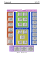
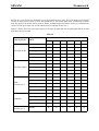
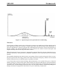
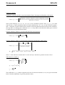
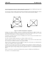
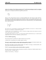
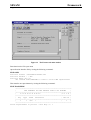
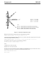
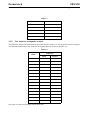
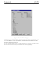
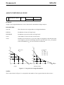
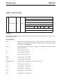
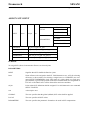
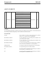
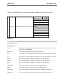
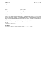
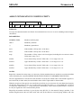
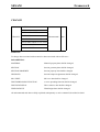
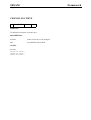
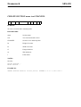
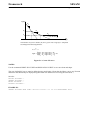
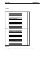
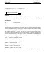
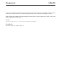
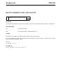
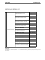
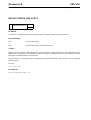
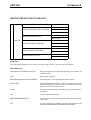
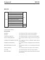
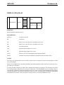
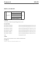
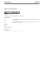
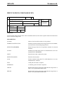
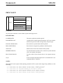
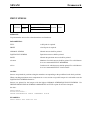
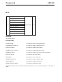
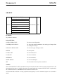
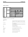
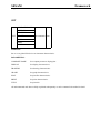
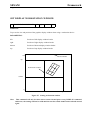
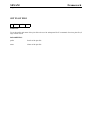
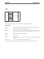
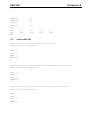
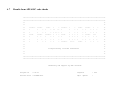
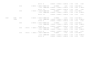
The relative coordinate system along the member has a coordinate 0.0 at first joint (end 1), 0.5 at midpoint
and 1.0 at the second joint (end 2).
2.9
Finite Elements
Relative positions
0.0
0.2
0.4
0.6
1.0
Joint
Node of Finite Element Model
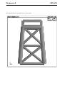
Figure 2.9 Member relative coordinate system
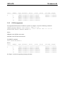
When calculating section forces in an arbitrary position along a member the forces will be calculated based
on the element forces at the start node of the element and the loads (distributed and point loads) applied to
the element. However, the code check positions are static positions along the member, i.e. not dynamically
moving positions trying to catch up any maximum or minimum forces / bending moments along the member. Hence, more frequent positions should be assigned when this is of great importance.
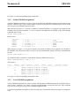
2.3.10 Local coordinate system
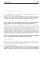
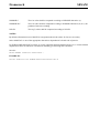
By default the member local coordinate system is based on the finite element local coordinate system (as
established in e.g. Preframe).
Member forces are always presented in the member local coordinate system. For modelling of stability
check properties and presentation (display and print) of member forces it is possible to re-assign a new
member local coordinate system.
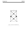
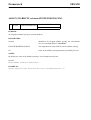
For tubular cross-sections which have equal stiffness properties independent of the local axes, the stability
axes should normally be oriented according to the frame of which the member is a part.
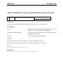
For non-tubular cross-sections having different moments of inertia about local axes it may be dangerous to
change the local axes. Changes to the orientation of the cross-section axes involve changes to the overall
stiffness properties of the finite element model, and should eventually involve a new finite element analysis.
But if axial force is the major load and bending moments are small, or the section has similar cross-section
properties about different axes, then the orientation of stability axes may perhaps be changed without introducing too large errors.
When joining several finite elements into one member, it is required that all finite elements have the same
local coordinate system.