1
TURKISH AIRLINES
A320
Full Flight Simulator
Technical Specification
30 July 2008
Turkish Airlines
A320 Full Flight Simulator Technical Specification
TABLE OF CONTENTS
1. GENERAL REQUIREMENTS .............................................................................. 10
2. CUSTOMISATION ORGANISATION ................................................................... 11
2.1. GENERAL CUSTOMISATION PRINCIPLE .................................................... 11
2.2. HARDWARE CUSTOMISATION PRINCIPLE ................................................ 11
2.3. SOFTWARE CUSTOMISATION PRINCIPLE ................................................. 11
2.4. A/C COMPUTER CUSTOMISATION ............................................................. 11
3. AIRCRAFT SIMULATION .................................................................................... 12
3.1. GENERAL ...................................................................................................... 12
3.2. EIS 2 SOFTWARE DATA LOADING .............................................................. 12
3.3. EGPWS SPECIFIC ENVIRONMENT ............................................................. 13
3.3.1. EGPWS Mode ......................................................................................... 13
3.3.2. Electronic Mountain ................................................................................. 13
3.3.2.1. Detailed Functions ............................................................................ 13
3.4. FMGC............................................................................................................. 14
3.4.1. FMS Files Loading................................................................................... 14
3.4.2. F M Preparation Copy/Load .................................................................... 14
3.4.2.1. General Performance: ....................................................................... 14
3.4.2.2. Link with IOS ..................................................................................... 15
3.4.3. FM Copy/Load ......................................................................................... 16
3.4.3.1. General Performance ........................................................................ 16
3.4.3.2. Link with IOS ..................................................................................... 16
3.5. ATIMS PRE-FANS CONFIGURATION........................................................... 16
3.5.1. Introduction .............................................................................................. 16
3.5.2. AOC Applications .................................................................................... 16
3.5.3. AOC/IOS Interface................................................................................... 17
3.5.3.1. Impending Messages Window .......................................................... 18
3.5.3.2. AOC Menu Page .............................................................................. 18
3.5.3.3. AOC REPLY Page ........................................................................... 20
3.6. WEATHER RADAR ........................................................................................ 21
3.6.1. Ground Mapping Function ....................................................................... 21
3.6.2. Cloud Model Definition ............................................................................ 21
3.6.3. Cloud Model Modification ........................................................................ 21
3.6.4. Cloud Model Effects ................................................................................ 21
3.6.5. Link With IOS........................................................................................... 22
3.7. TCAS.............................................................................................................. 23
3.7.1. TCAS Environment .................................................................................. 23
3.7.1.1. TCAS airport traffic ........................................................................... 23
3.7.1.2. TCAS scenarios definition ................................................................. 24
3.7.2. Link with IOS ........................................................................................... 26
3.7.3. Scenario and Airport Traffic Modification ................................................. 26
3.8. SYSTEM WITH PARTIAL SIMULATION SPECIFIC REQUIREMENTS ........ 26
3.8.1. External Lighting ...................................................................................... 26
3.8.2. Air Conditioning And Cabin Pressurisation .............................................. 26
3.8.3. Electrical Power ....................................................................................... 26
Page 2 of 102
Turkish Airlines
A320 Full Flight Simulator Technical Specification
3.8.4. Oxygen System (crew and passengers) .................................................. 26
3.8.5. Communication Systems ......................................................................... 27
3.8.5.1. General communication .................................................................... 27
3.8.5.2. CIDS : Cabin Ready .......................................................................... 27
3.8.6. Flight Recorder System ........................................................................... 28
3.8.7. Window Heat ........................................................................................... 28
3.8.8. Circuit Breakers ....................................................................................... 28
3.8.9. Windscreen Wipers And Rain Repellent System ..................................... 28
3.8.10. Sensors ................................................................................................. 28
3.9. MALFUNCTIONS ........................................................................................... 28
THE IOS MALFUNCTION PAGES SHALL BE CUSTOMISED ACCORDING TO A/C VERSION
SELECTED AT FFS LAUNCHING.................................................................................. 28
3.10. OEB IMPLEMENTATION UTILITY ............................................................... 28
4. ENVIRONMENT SIMULATION ............................................................................ 29
4.1. ATMOSPHERE .............................................................................................. 29
4.1.1. Winds And Turbulence ............................................................................ 29
4.1.1.1. Windshear and microburst ................................................................ 29
4.1.1.2. Wind vector ....................................................................................... 30
4.1.1.3. Turbulence ........................................................................................ 30
4.1.1.4. Effects, selection and logic................................................................ 31
4.1.2. Icing Conditions ....................................................................................... 31
4.1.3. Temperature And Atmosphere Pressure ................................................. 31
4.2. RUNWAY ....................................................................................................... 31
4.2.1. Runway Type .......................................................................................... 31
4.2.2. Runway Conditions.................................................................................. 32
4.3. TERRAIN PROFILE ....................................................................................... 32
4.4. SOUND SIMULATION.................................................................................... 32
4.5. NAVIGATION AND COMMUNICATION ENVIRONMENT SIMULATION ....... 33
4.5.1. Navaids Data-base .................................................................................. 33
4.5.2. Navaids Processing ................................................................................. 34
4.5.3. Navaids Failure........................................................................................ 34
4.5.4. Communication Stations .......................................................................... 34
4.5.5. RT and ATC Radio Chatter ..................................................................... 34
4.5.6. ATIS Simulation ....................................................................................... 35
4.5.6.1. General performance ........................................................................ 35
4.5.6.2. Links with IOS ................................................................................... 35
4.5.6.3. ATIS message modification .............................................................. 35
4.6. SMOKE GENERATION .................................................................................. 36
5. TOLERANCES ..................................................................................................... 37
6. FLIGHT COMPARTMENT ................................................................................... 38
6.1. GENERAL ...................................................................................................... 38
6.2. FLIGHT COMPARTMENT GENERAL ARRANGEMENT ............................... 38
6.3. LIGHTING ...................................................................................................... 38
6.4. VENTILATION AND AIR-CONDITIONING ..................................................... 39
6.5. INTERIOR NOISE LEVEL .............................................................................. 39
6.6. TELEPHONE AND BOOM SET ...................................................................... 39
Page 3 of 102
Turkish Airlines
A320 Full Flight Simulator Technical Specification
6.6.1. Telephone ............................................................................................... 39
6.6.2. Boom Set ................................................................................................. 40
6.7. WALKWAY PLATFORM DRAWBRIDGE ....................................................... 40
6.8. MISCELLANEOUS ......................................................................................... 41
7. INSTRUCTOR OPERATING STATION (IOS)...................................................... 42
7.1. GENERAL ...................................................................................................... 42
7.2. INSTRUCTOR STATION LAYOUT ................................................................ 42
7.2.1. Hadrware Layout ..................................................................................... 42
7.2.2. Screens. .................................................................................................. 43
7.2.3. FFIOS Seat ............................................................................................. 43
7.2.3.1. Instructor Seat:.................................................................................. 43
7.2.3.2. Observer Seats: ................................................................................ 44
7.2.4. Pushbuttons, Panels and Controls Located on the Instructor Seat ......... 44
7.2.4.1. Hardware Push Buttons Panels ........................................................ 44
7.2.4.2. Simulator and Motion&C/L Emergency Stop Buttons:....................... 44
7.2.4.3. A/C Communication Panel ................................................................ 44
7.2.4.4. Sound Control ................................................................................... 44
7.2.4.5. Overhead Light Switch ...................................................................... 44
7.2.4.6. Lighting Controls ............................................................................... 45
7.2.4.7. Telephone ......................................................................................... 45
7.2.4.8. Clock with stop watch ....................................................................... 45
7.2.4.9. Controls for Monitor Brightness and Contrast ................................... 45
7.2.5. Controls not Located on the Instructor Seat. ........................................... 45
7.2.5.1. Flight Compartment Air Conditioning Control .................................... 45
7.2.5.2. Remote Control Box for IOS ............................................................. 45
7.2.6. Functions Controllable From The Touch screens Pages ......................... 45
7.2.6.1. Freeze Controls ................................................................................ 46
7.2.6.2. Reset ................................................................................................ 46
7.2.6.3. Services ............................................................................................ 47
7.2.6.4. Airports ............................................................................................. 48
7.2.6.5. Weather ............................................................................................ 48
7.2.6.6. Visual ................................................................................................ 48
7.2.6.7. Navaids ............................................................................................. 49
7.2.6.8. Communications ............................................................................... 49
7.2.6.9. Nose Wheel Steering function........................................................... 49
7.2.6.10. Doors/Cabin ready .......................................................................... 50
7.2.6.11. Navigation Maps ............................................................................. 50
7.2.6.12. Permanent visualisation of parameters ........................................... 51
7.2.6.13. Snapshot/Recall .............................................................................. 51
7.2.6.14. Environment conditions pre-set....................................................... 52
7.2.6.15. Hard copy........................................................................................ 52
7.2.6.16. Position initialisation ........................................................................ 52
7.2.6.17. Malfunctions .................................................................................... 53
7.2.6.18. FS status ......................................................................................... 54
7.2.6.19. Flight conditions .............................................................................. 55
7.2.6.20. A/C Loading .................................................................................... 55
7.2.6.21. Crash Indication .............................................................................. 55
Page 4 of 102
Turkish Airlines
A320 Full Flight Simulator Technical Specification
7.2.6.22. ATIS ................................................................................................ 55
7.2.6.23. SMOKE ........................................................................................... 56
7.2.6.24. A/C Status ....................................................................................... 56
7.2.6.25. Quick Set Up ................................................................................... 56
7.2.6.26. Help function ................................................................................... 56
7.2.6.27. Maintenance function ...................................................................... 56
7.2.6.28. Maintenance mode access ............................................................. 56
7.2.6.29. Lesson plans ................................................................................... 57
7.2.6.30. Virtual Printer .................................................................................. 57
7.2.6.31. F M Preparation COPY/LOAD ........................................................ 57
7.2.6.32. Electronic Mountain ........................................................................ 57
7.2.6.33. TCAS scenario ................................................................................ 57
7.2.6.34. Weather Radar................................................................................ 57
7.2.6.35. ATIMS messages control ................................................................ 57
7.2.6.36. Radio Chatter messages ................................................................ 58
7.2.6.37. Simulator Session Recording control page ..................................... 58
7.3. USER’S GUIDE .............................................................................................. 58
8. COMPUTER, INTERFACE AND POWER SUPPLIES ......................................... 59
8.1. FS COMPUTER COMPLEX AND PERIPHERALS ......................................... 59
8.1.1. Computers Type ...................................................................................... 59
8.1.2. Peripherals .............................................................................................. 59
8.1.3. Operating Systems .................................................................................. 60
8.1.4. Network ................................................................................................... 61
8.1.5. Spare Capacities ..................................................................................... 61
8.1.6. Software Development Facility ................................................................ 61
8.2. COMPUTER PROGRAM SYSTEM – FS SOFTWARE ................................... 62
8.2.1. General .................................................................................................... 62
8.2.2. FS Real-Time Executive Programs ......................................................... 62
8.2.3. Simulation Programs ............................................................................... 62
8.2.4. Utility Program And Software Control ...................................................... 62
8.2.4.1. FS Support Programs ....................................................................... 62
8.2.4.2. FFS performance test system ........................................................... 63
8.2.4.3. Software control, change and configuration control .......................... 66
8.2.4.4. Software supply and documentation : ............................................... 66
8.3. INTERFACE ................................................................................................... 67
8.3.1. General .................................................................................................... 67
8.3.2. Printed Circuits Boards Assemblies......................................................... 67
8.3.3. System Configuration .............................................................................. 67
8.3.4. Accessibility to Boards, LRUs and A/C Components............................... 67
8.3.5. Expansion Capacity ................................................................................. 67
8.3.6. Softcopy Of Firmware .............................................................................. 68
8.3.7. Interface INPUT/OUTPUT spare time ..................................................... 68
8.4. POWER SUPPLIES ....................................................................................... 68
8.4.1. Main Power Supply.................................................................................. 68
8.4.1.1. General ............................................................................................. 68
8.4.1.2. Insulation .......................................................................................... 68
8.4.2. FS Power Supplies .................................................................................. 68
Page 5 of 102
Turkish Airlines
A320 Full Flight Simulator Technical Specification
9. DIGITAL CONTROL LOADING SYSTEM ........................................................... 69
9.1. GENERAL DESCRIPTION ............................................................................. 69
9.2. HARDWARE REQUIREMENTS ..................................................................... 69
9.2.1. Power Requirements ............................................................................... 69
9.2.2. Start of Electro-Mechanical Actuator ....................................................... 69
9.2.3. Failure Detection ..................................................................................... 69
9.2.4. Reset ....................................................................................................... 69
9.2.5. Safety Requirements ............................................................................... 69
9.2.6. Recording Devices .................................................................................. 70
10. MOTION SYSTEM ............................................................................................. 71
10.1. GENERAL DESCRIPTION ........................................................................... 71
10.2. AXIS OF MOTION ........................................................................................ 71
10.3. WEIGHT INCREASE ALLOWANCE............................................................. 71
10.4. PERFORMANCE ......................................................................................... 71
10.5. SAFETY REQUIREMENTS .......................................................................... 72
10.6. TESTING AND ALIGNMENT ........................................................................ 73
10.6.1. QTG....................................................................................................... 73
10.6.2. Motion System Diagnostics ................................................................... 73
10.6.3. Alignment Procedure ............................................................................. 73
11. VISUAL SYSTEM ............................................................................................... 74
11.1. GENERAL .................................................................................................... 74
11.2. OPTICS ........................................................................................................ 74
11.3. CUSTOMISED AIRPORT MODEL ALIGNMENT.......................................... 74
11.4. PARAMETERS SETTING ............................................................................ 74
12. OPERATION AND MAINTENANCE .................................................................. 75
12.1. OPERATION ................................................................................................ 75
12.1.1. Start Up and Shut Down Procedures..................................................... 75
12.1.2. Multiversions.......................................................................................... 75
12.1.3. Air Conditioning ..................................................................................... 76
12.1.4. Overheat Detection................................................................................ 76
12.2. ON-LINE DIAGNOSTICS ............................................................................. 76
12.2.1. General .................................................................................................. 76
12.2.2. On Line Diagnostic Main Features ........................................................ 77
12.3. OFF-LINE DIAGNOSTICS ........................................................................... 78
12.3.1. Interface ................................................................................................ 78
12.3.2. Motion and CLS ..................................................................................... 78
12.3.3. Instructor Station ................................................................................... 78
12.3.4. Computer Complex................................................................................ 79
12.3.5. Sound .................................................................................................... 79
12.3.6. Smoke Generator .................................................................................. 79
12.4. MAINTENANCE FEATURES ....................................................................... 79
12.4.1. Electronics ............................................................................................. 79
12.4.2. Cockpit .................................................................................................. 79
12.4.3. Aircraft Boxes ........................................................................................ 79
12.4.4. Visual System ........................................................................................ 79
Page 6 of 102
Turkish Airlines
A320 Full Flight Simulator Technical Specification
12.4.5. Computerised Documentation ............................................................... 80
12.4.6. Motion And Control Loading System ..................................................... 80
13. QUALITY OF CONSTRUCTION AND SAFETY REQUIREMENTS .................. 82
13.1. MATERIAL, PARTS, PROCESSES AND FINISHES .................................... 82
13.1.1. Standard Parts....................................................................................... 82
13.1.2. Metallic Parts ......................................................................................... 82
13.1.3. Non Metallic Parts ................................................................................. 82
13.1.4. Flammable Materials ............................................................................. 82
13.1.5. Finishes ................................................................................................. 83
13.1.6. Guaranteed Weight ............................................................................... 83
13.1.7. Wiring .................................................................................................... 83
13.2. INTERCHANGEABILITY & LRU REPLACEMENT ....................................... 83
13.3. MARKINGS .................................................................................................. 84
13.3.1. General .................................................................................................. 84
13.3.2. LRU Markings ........................................................................................ 84
13.3.3. Localisation Markings ............................................................................ 84
13.3.4. Cable Connection .................................................................................. 84
13.3.5. Wires ..................................................................................................... 84
13.3.6. Firmware ............................................................................................... 84
13.3.7. Safety Marking....................................................................................... 84
13.3.8. Motion System, Control Forces, Simulated Systems ............................. 85
13.4. HEALTH AND SAFETY QUALIFICATION REQUIREMENTS ...................... 85
13.4.1. General .................................................................................................. 85
13.4.2. Emergency Exits.................................................................................... 85
13.4.3. Emergency Power Off ........................................................................... 85
13.4.4. Fire Protection ....................................................................................... 85
13.4.5. EMC Electro-Magnetic Compatibility ..................................................... 86
14. SCHEDULE AND PROJECT FOLLOW-UP ....................................................... 87
14.1. AUTHOROTIES QTG ................................................................................... 87
14.2. IN-PLANT THY'S FOLLOW-UP .................................................................... 87
14.3. PROGRESS MEETINGS ............................................................................. 87
14.4. UPDATE OF SELLER’S SPECIFICATION ................................................... 88
15. ACCEPTANCE ................................................................................................... 89
15.1. GENERAL .................................................................................................... 89
15.2. ACCEPTANCE TEST MANUAL (ATM) ........................................................ 89
15.2.1. Acceptance Test Manual ....................................................................... 89
15.2.2. Scope .................................................................................................... 89
15.2.3. Content .................................................................................................. 89
15.2.4. Schedule ............................................................................................... 90
15.3. REGULATORY AUTHORITIES QUALIFICATION TEST GUIDE ................. 90
15.3.1. Documents ............................................................................................ 90
15.3.2. Hardware Facilities For QTG Tests ....................................................... 90
15.4. DISCREPANCY REPORTS ......................................................................... 90
15.5. IN-PLANT ACCEPTANCE ............................................................................ 91
15.5.1. Hardware Acceptance Of FFS ............................................................... 91
Page 7 of 102
Turkish Airlines
A320 Full Flight Simulator Technical Specification
15.5.2. Functional Acceptance .......................................................................... 91
15.6. ON-SITE ACCEPTANCE ............................................................................. 92
15.6.1. On-Site Acceptance............................................................................... 92
15.6.2. DR Clearence After RFT ....................................................................... 92
15.6.3. Regulatory Authority Approval ............................................................... 92
16. ON SITE INSTALLATION .................................................................................. 93
16.1. FACILITY REQUIREMENTS ........................................................................ 93
16.2. INSTALLATION ............................................................................................ 93
16.3. HANDLING ................................................................................................... 93
17. TECHNICAL SUPPORT..................................................................................... 94
17.1. TECHNICAL PUBLICATION ........................................................................ 94
17.1.1. Publication Content ............................................................................... 94
17.2. FIELD SERVICE ENGINEER ....................................................................... 94
17.3. SPARE PARTS MAINTENANCE TOOLS AND TEST EQUIPMENT ............ 94
17.4. SIMULATOR LIFE CYCLE SUPPORT PARAMATERS ................................ 95
17.4.1. Preventative Maintenance ..................................................................... 95
17.4.2. Consumable Spare Cost ....................................................................... 95
17.5. OPERATION AND MAINTENANCE TRAINING ........................................... 95
17.5.1. Hardware Training (8 people) ................................................................ 96
17.5.2. Software Training (6 people) ................................................................. 96
18. RELIABILITY ..................................................................................................... 97
18.1. RELIABILITY REQUIREMENTS .................................................................. 97
18.2. RELIABILITY DEMONSTRATION ................................................................ 98
19. OPTIONS ........................................................................................................... 99
19.1. DEBRIEFING STATION ............................................................................... 99
19.1.1. GENERAL LAYOUT .............................................................................. 99
19.1.2. WINDOWS ............................................................................................ 99
19.1.2.1. Cockpit Environment video/sound replay ........................................ 99
19.1.2.2. Aircraft external 3D view ............................................................... 100
19.1.2.3. Replayed instruments ................................................................... 100
19.1.2.4. Navigation charts and graphs ....................................................... 100
19.1.2.5. Events management ..................................................................... 101
19.1.2.6. Navigation through the simulator session recorded file ................. 101
19.1.3. CONFIDENTIALITY............................................................................. 101
19.1.3.1. Deletion of Simulator session recorded file ................................... 101
19.1.3.2. Data protection.............................................................................. 101
19.1.4. DATA STORAGE ................................................................................ 101
19.2. SPARE COMPUTERS ............................................................................... 102
19.3. SPARE SOFTWARE DEVELOPMENT FACILITY ...................................... 102
19.4. TEST BENCH ............................................................................................. 102
19.5. ELECTRONIC FLIGHT BAG ...................................................................... 102
SUMMARY
Page 8 of 102
Turkish Airlines
A320 Full Flight Simulator Technical Specification
This Technical Specification describes Turkish Airlines minimum requirements for an
A320 Full Flight Simulator without Visual System (FS)
Seller will specify, in a detailed Technical Specification, how these requirements are
fulfilled.
Seller will produce more particularly a Compliance Matrix to match the herein Turkish
Airlines Technical Specification to Seller Technical Specification.
Seller Technical Specification which will include notably, a detailed description of the
hardware and software of the FS configuration together with all necessary diagrams,
schematics, photographs, general layout, motion envelope with 3 LCoS projectors
visual system with minimum 180°X40° collimated mirror.
Three hard and soft copies of the Technical Specification shall be sent to Turkish
Airlines.
Definitions:
THY: “THY” means Turkish Airlines Inc.
Seller: “Seller” means FS manufacturer.
Flight Simulator (FS): “Flight Simulator” or “FS “ means the flight simulator including
optic system and integrated with A320 Aircraft Data Package, Aircraft Parts and
Aircraft Equipment. FS can be integrated with any Level D Visual System.
Full Flight Simulator (FFS): “Full Flight Simulator“ or “FFS” means FS integrated with
level D Visual System.
DPE: “DPE” means A320 Aircraft Data Package, Aircraft Parts and Aircraft Equipment.
This Technical Specification has been generated by modifying
AIRBUS Standard A320 Full Flight Simulator Specification.
Page 9 of 102
Turkish Airlines
A320 Full Flight Simulator Technical Specification
1. GENERAL REQUIREMENTS
Airbus A320 FS shall be based on Airbus standard 1.6.
THY will have the capability to configure the FS to 2 standard models listed below:
•
•
A320-232 V2527- A5
A320-214 CFM56-5B4
FS will have:
• Re-target / Re-hosted FMGC,
• Simulated EFCS,
• Simulated FWC,
FS shall be designed and approved without any restriction for certification as Level D
In compliance with:
• JAR-STD 1A. (Amendment 3)
And
• FAA AC 120-40 B.
THY prefers FS to meet also the proposed draft documents of JAA and FAA such as
draft AC120-40C.
In case JAR and/or FAA Advisory Circular change until the contract sign, the
contract shall define the valid reference.
The FFS will be used for ZFTT (Zero Flight Time Training), i.e. the based training
performed on real A/C will be replaced by a simulator session. For that purpose,
in addition to level D conformity, a specific attention will be taken, concerning
A/C representatively to the taxi, take-off, circling, approach and landing phases.
Additional tests and data necessary for the "base training phase" simulation
(motion, sound, ground handling, special effect...) will be provided through the
data package and shall be implemented by the Seller.
• ARINC Report 434 Requirements
The requirements of Arinc Report 434 shall be considered as a reference addition to
THY Technical Specification. Seller shall meet this requirement as well.
Upgrade capability: Seller shall design the FS to allow future hardware and /or
software expansion while maintaining the architecture unchanged. In his Technical
Specification, Seller shall explain the limits and the solutions in respect of expansion.
Note: Seller shall provide the necessary hardware and software to integrate all pin
programming available on the aircraft. These pin-programmed functions shall be
implemented for each model and shall be activated by soft buttons on IOS.
Page 10 of 102
Turkish Airlines
A320 Full Flight Simulator Technical Specification
2. CUSTOMISATION ORGANISATION
2.1. GENERAL CUSTOMISATION PRINCIPLE
Each customised version that requires reloading FS should be identified by a
dedicated name. Reloading for customised version shall be available after verification
of the requested configuration.
The operable current load shall also be displayed on the information window above the
flight compartment door such like :
“A320 / CFM56-5B4 load is in progress”, or “Flight In Progress, A/C Version …etc.
THY will be able to easily modify this message.
2.2. HARDWARE CUSTOMISATION PRINCIPLE
•
A320-214 CFM56-5B4 to/from A320-232 V2527-A5 Conversion Timing:
Seller shall propose the suitable solution (if required) for the entire conversion of
A320-214 CFM56-5B4 from/to A320-232 V2527-A5 versions within 15 minutes.
2.3. SOFTWARE CUSTOMISATION PRINCIPLE
Software code duplication shall be avoided and the naming convention for all modules
and codes shall be done properly that the software can be easily maintained.
Seller shall provide a document stating his customisation principles and provide a list
of all customisation flags.
Impacted and read only files shall be listed.
2.4. A/C COMPUTER CUSTOMISATION
The A/C computer (refer to paragraph 3.1) customisation shall enable the FS to reflect
all the A/C simulated versions as defined in chapter 1.
The A/C computer customisation shall automatically select and activate the proper A/C
computer configuration at simulation loading without any operator intervention.
Page 11 of 102
Turkish Airlines
A320 Full Flight Simulator Technical Specification
3. AIRCRAFT SIMULATION
3.1. GENERAL
The simulation shall be based on the principle of the full representation of the flight
characteristics of the various systems and the environment of the aircraft, by means of
logical and mathematical models, issued from the aircraft manufacturer data package.
In particular, simulated systems shall operate as the real A/C ones with the same
performances,
results
and
redundancy.
Seller shall provide substitution simulation each time information is missing in the data
package.
In the following, A/C computers shall mean the representation of real A/C computers
whatever the solution chosen by Seller: Stimulation, simulation, rehosting, retargeting.
Seller shall include all necessary computer, equipment and simulation model to
complete the A/C representation.
Concerning the Main A/C Computers, Seller shall propose and explain his solutions to
represent the A/C at the level defined in chapter 1.
All the Circuit Breakers (CBs) shall be fully simulated.
Seller solutions shall comply with the A/C computer customisation (refer to paragraph
2.4) and the following statements:
• All variables of ICD’s, logical sheets, mathematics models, etc, included in
datapackage shall be easily identifiable
• All A/C pin programming shall be selectable and activated through software
variables and controlled via IOS.
• Notwithstanding IOS inputs, no spurious effects on A/C computers shall appear.
• Provisional Hardware and Software Input/Output including wiring shall be installed
to allow future updates.
• Main A/C computer reset function shall be provided at the IOS (refer to paragraph
7.2.6.2), to perform an individual computer quick re-initialisation to restore normal
operation in accordance with current FS conditions. The reset shall not be
hampered by the A/C conditions (flight phases, engines off, ground, flight, etc).
• Any Each A/C computer interface shall be software controlled even if two are
connected together.
• Use of Industrial off the shelf standards
• Better or at least same timeframe revision capability as the real A/C boxes.
• Better overall revision cost than the real A/C box.
• ARINC 610B functionality shall be applied.
3.2. EIS 2 SOFTWARE DATA LOADING
In order to ease the update of DMCs and DUs, the Seller shall provide a solution to
upload DMCs and DUs with new EIS2 software version through a user-friendly
system. However A/C HMI ”reproduction” is not a requirement.
The system shall be able to identify P/N and S/N of each LRU along with their
currently loaded EIS2 software P/N. The result of this identification shall be
displayed for operator reference and may be printed on request to a printer or to a
file. Current date, simulator identification (as defined in §8.1.1) and loading result
in clear language shall also be indicated.
Page 12 of 102
Turkish Airlines
A320 Full Flight Simulator Technical Specification
Initial DMC upload with new software shall be entirely automated. No operator action
shall be required except software P/N selection and upload activation.
Comprehensive error logging and reporting shall be provided.
No change on A/C EIS2 software media content shall be performed. A facility aimed
to archive and manage at least the two last versions (P/N) of A/C EIS2 software
media content shall be provided.
Cross loading of embedded software between LRUs shall then be enabled and
proposed to the operator if software P/N are not identical. No operator action shall be
required except source and destination LRU selection and cross loading activation.
Automated cross loading, error reporting and logging shall provide the same facilities
than A/C embedded cross-loading software as a minimum.
In any case no LRU dismounting or LRU swapping shall be required. The complete
loading (3DMCs and 6 DUs) shall not take longer than the quickest process on aircraft.
3.3. EGPWS SPECIFIC ENVIRONMENT
3.3.1. EGPWS Mode
Terrain profiles in the vicinity of the airports have to be correlated to EGPWS terrain
database.
For this purpose10 of suitable airports will be selected by THY during the project. In
the vicinity of these airports, all EGPWS functions will be operative with full correlation
between
environment
profile
and
EGPWS
terrain
database.
For airports where visual profile is not correlated with EGPWS terrain database,
EGPWS terrain detection function and terrain display on ND’s shall be automatically
inhibited when visibility is greater than 300m. This automatic inhibition shall be deselectable with IOS.
For the installation of RAAS and SAM in the future, inhibit switches shall be offered as
provision as necessary.
3.3.2. Electronic Mountain
An icon will be available on the instructor station to activate the EGPWS on request.
(Refer to paragraph 7.2.6.32)
When EGPWS activated, the radio altitude will decrease. The only effects in the
cockpit will be:
• The radio altitude value change on the PFD’s.
• The GPWS aural and visual warning.
3.3.2.1. Detailed Functions
•
•
•
•
This icon shall not be operational when the aircraft is on ground.
The function shall be de-activated either by pulling back on the side stick or by
reselecting the icon. When the function is de-activated, the radio altitude will return
gradually to normal operation.
The radio altitude shall drop down to 30 feet maximum and remain at this value in
order to prevent unwanted crash in case of insufficient or no pilot action.
No correlation with the visual system is requested.
Page 13 of 102
Turkish Airlines
A320 Full Flight Simulator Technical Specification
3.4. FMGC
THY prefers the re-targeted/rehosted solution for FMGC system simulation.
3.4.1. FMS Files Loading
Note: The following requirements can be suitable for FMS2, according to their
respective characteristics. The solution shall be applicable inside the scope of each
FM.
Principle :Seller shall provide a way to load all FMS files via the network (Software
Operational Program, OPC, AMI, Performance Data Base, Magnetic Variation Data
Base, Navigation Data Base).
The process of FMS loading shall be provided with the following features:
1. Automatic mode: The ability to load and to control the loading for any A/C
version during normal training phases. (Version changes).
In this case the process of FMS loading shall be fully automatic. If the new
aircraft version does not request new FMS files configuration, the FMS shall
not be reloaded and User shall be advised.
2. Manual mode: The ability to load and to control the FMS loading when the
simulation is running. The FMS loading process shall be initiated (with the
choice for one or both FMS) through the main start menu displayed on the
simulation control console.
In addition, the loading menu shall propose the capability to display the
FMS current configuration.
3. For features 1 or 2, the ability to generate reports during the FMS
loading. The operator shall be advised on FMS loading status including
as a minimum: - Previous and new configurations display.
- FMS loading in progress
- FMS loading complete
- FMS loading fail (problem detected during loading). In this case, the
seller shall provide a solution to reload FMS.
4. The ability to load the both FMS at the same time.
5. The maximum loading time shall not exceed the loading time for 1 FMS
when using the MDDU.
6. The FMS Loading back-up solution shall be to use the MDDU as on aircraft.
FMS updates shall also be available by Multi Disk Driver.
At the end of the simulation loading, an automatic check shall be provided to guaranty
the consistency between FMS files loaded and FMS files selected within A/C version
Loading time of FMS files to the rehosted FMGC should not exceed loading time with
Portable Data Loader to the H/W FMGC.
3.4.2. F M Preparation Copy/Load
3.4.2.1. General Performance:
The purpose is to provide the user with the facility to load the FMGC with any FM
Preparation (FMPrep) that would have been previously inserted through the Captain or
F/O MCDU.
Page 14 of 102
Turkish Airlines
A320 Full Flight Simulator Technical Specification
F M Preparation COPY/LOAD
PERMANENT
TEMPORARY
NETWORK IMPORT
FMPrep
FMPrep
FMPrep
1 XXX
2 YYY
1 LFBO/LFPO
2 YYY
3 ZZZ
1 ZZZYYYYYYXXX
Created: 02/10
14:55
2…
N…
(50 FMPrep
maximum)
LOAD
N…
COPY
TEMPORARY
The FMPrep shall mean and include all MCDU data pages as entered during cockpit
preparation such as:
INIT A &B, F-PLN, RAD NAV, PROG, PERF, SEC F-PLN, etc.
The complete copy/load process shall not take more than 30 seconds.
The load function facility shall be extended to FMPrep files stored on host media
(disks, network…).
3.4.2.2. Link with IOS
The following page shall be accessible through Master Index page.
•
•
•
•
•
The permanent FMPrep shall be sorted in predefined order (to comply with the
syllabus).
Windows “permanent” and “import” shall have the capability to display up to 10
FMPrep. Beyond this number the window display shall be controlled through scroll
bars. However, for import window, the most recent FMPrep must always be
displayed at the bottom of window.
The permanent and import FMPrep shall be identified by their FMPrep name (with
minimum 12 characters field).
The “LOAD” button shall be active if a unique FMPrep has been selected in one of
the 5 windows. By default, the last temporary FMPrep stored shall be selected.
The “LOAD” button shall be greyed if no FMPrep is selected.
The “COPY TEMPORARY” button shall allow to store a temporary FMPrep which
will be manually entered during the current session. A default name (Departure
airport/Destination airport) shall be automatically given and shall be displayed at
the bottom of the temporary FMPrep list.This list shall be limited to min 5 last
FMPrep stored. All the temporary FMPrep shall be deleted after a simulation
version change.
Page 15 of 102
Turkish Airlines
A320 Full Flight Simulator Technical Specification
•
Maintenance Mode:
This mode shall be applicable only to the permanent FMPrep
-The “COPY TEMPORARY” button shall be replaced by a “COPY PERMANENT”
button with the same capabilities (but stores the new FMPrep in the “permanent”
window, at the bottom of the list).
- A “REMOVE PERMANENT” button shall allow to remove a selected permanent
FMPrep.
- In addition, it shall be possible to modify the FMPrep names and the FMPrep
order in the list.
3.4.3. FM Copy/Load
3.4.3.1. General Performance
The purpose is to provide the user with the facilities to Copy (store) or Load (reload)
FM parameters as defined in paragraph 3.4.2.1
This function will cause the FMGC to internally store or reload the data.
The complete store/reload process shall not take more than 5 seconds.
3.4.3.2. Link with IOS
FM Copy/Load functions shall be directly accessible through the IOS pages.
• FM COPY
• FM LOAD
3.5. ATIMS PRE-FANS CONFIGURATION
3.5.1. Introduction
The Air Traffic and Information Management System (ATIMS) in Pre-FANS A
configuration comprises Airline Operational Control (AOC).
3.5.2. AOC Applications
A full simulation shall be provided for AOC applications listed below. This means that
the interface between cockpit and ground station (IOS) shall be fully simulated.
The Seller shall provide:
• A solution to load all AOC files via the network (applications and database). The
applications and database shall be directly issued from the AOC A/C floppy disks,
as defined in A320 Std 1.6 Standard Equipment List
• A dedicated connector in the ATSU cabinet in order to plug an A/C Portable Data
Loader.
All AOC applications shall be available through the MCDU.
For the AOC applications not listed in the table below but available through the MCDU,
a message “NOT SUPPORTED BY SIMULATION” shall be displayed in the IOS AOC
LOG page.
Flight ops
application
Transmission
Initiated on
ASSOCIATED
MESSAGE INTENT
DOWNLINK AND
UPLINK MESSAGES
Page 16 of 102
Turkish Airlines
A320 Full Flight Simulator Technical Specification
Downlink
reports
Automatic
DN: Refuelling Report
Automatic
DN: OUT Report
Automatic
Automatic
Automatic
DN: OFF Report
DN: ON Report
DN: IN Report
Automatic
DN: Return IN Report
F/PLAN init*
MCDU
IOS
WXR **
MCDU
ATIS ***
MCDU
DN: F/PLAN init
request
UP: F/PLAN INIT
DN: WXR Request
(Actual /Forecast )
UP: WXR information
(Actual/Forecast)
DN: ATIS Request UP:
ATIS information
VOICE
CONTACT
MCDU
IOS
DN: Voice Contact
UP: Voice Contact
FREE
TEXT
MCDU
IOS
DN: Free text
UP: Free text
MCDU
DN: Delay Report
DELAY
REPORT
A/C sends fuel information to
the ground
OUT = A/C on ground, taxiing
(ground speed >0)
OFF = A/C in flight
ON= A/C landed, taxiing to gate
IN= A/C on ground, at gate, at
least one door open
Return In = A/C has returned to
the terminal without taking off
Ground sends a flight plan and
associated performance data to
the Aircraft
The crew initiates a specific
weather request downlink for
specifics airports
The crew initiates a specific
ATIS request downlink for
specifics airports
The crew can be contacted by
the operations via a specific
media (VHF/HF)
On IOS, an alphanumeric
keyboard shall be displayed
to generate free text
Informs the ground of an en
route delay
*Flight plan parameters shall be at minimum: Departure
Airport/SID/waypoints/airways/STAR/Arrival airport/Alternate Airports.
** Weather actual (and ATIS) reply information shall be correlated with
corresponding weather airport simulator parameters (refer to paragraph 7.2.4.14). In
addition, a set of 5 predefined weather actual messages (METAR standard) shall
also be proposed.
For weather forecast request, a set of 5 predefined weather forecast messages
(TAF standard) shall be proposed in weather reply page. By default 1 set of
predefined weather messages shall be pre-selected (standard environment).
*** Only if ATIS application is available.
3.5.3. AOC/IOS Interface
Specific AOC pages shall be provided on the IOS to simulate the communication
between the ground and the aircraft.
For each AOC page, the following permanent buttons shall be provided:
Page 17 of 102
Turkish Airlines
A320 Full Flight Simulator Technical Specification
•
AOC Menu to call the AOC main menu page (If not selected). This page shall be
selected by a dedicated icon on the instructor station (refer to paragraph 7.2.4.37
AOC Log to call the AOC Log page. This button shall flash at the reception of a
downlink message from the aircraft and until the message is answered. The
message shall also come up automatically and flash in FFS Status dedicated area
(refer to paragraph 7.2.4.18).
3.5.3.1. Impending Messages Window
A unique Impending Window shall be provided and displayed either on the AOC
MENU page or on the AOC REPLY page. The Impending window shall provide the
user the possibilities to manage the messages.
This impending window shall include the following functions:
•
•
•
•
•
•
•
•
The Impending window shall store the pre-selected AOC Uplink or Reply
messages for processing.
The maximum number of messages stored in the list shall be 10.
The last pre-selected message shall be displayed at the bottom of the list.
The user shall have the possibility to select a message. The selected message
shall
be displayed in reverse video. Without selection, the first message of the list shall
be selected by default.
The seller shall provide a way to change message parameters (type and/or
values).
SEND or REMOVE buttons shall permit to send/remove the selected message.
These buttons shall be activated only if the selected message is visible on the
screen.
AOC LOG page shall be automatically displayed after a SEND action.
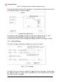
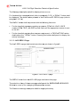
3.5.3.2. AOC Menu Page
The AOC MENU page shall contain functions as per shown in figure 6.
Page 18 of 102
Turkish
h Airlines
s
A320 Fu
ull Flight Siimulator Te
echnical Sp
pecification
n
This pa
age shall lisst the AOC
C uplink me
essages. The
T Impend
ding messages window shall
come up
u after sellection of any
a messa
ages.
Figure
e 6 AOC Menu
M
Page
The fun
nctions of the
t impend
ding windo
ow are desc
cribed in paragraph.3
p
3.5.3.1 The
e
“CLEAR
R FOR NE
EW SESSIO
ON” button
n shall clea
ar all the prrevious AO
OC
commu
unications (Reset of the
t impend
ding messa
ages and AOC
A
LOG page contents).
3.5.3.3. AOC LOG Page
The AO
OC LOG pa
age shall co
ontain funcctions as per shown in figure 7.
The AO
OC LOG button from
m any otherr AOC pag
ge shall select this pa
age. It sha
all display
the com
mplete hisstory of current AOC
C communiication in chronologi
c
cal order including
uplink and
a downliink messag
ges.
Page 19 of 102
2
Turkish
h Airlines
s
A320 Fu
ull Flight Siimulator Te
echnical Sp
pecification
n
The Me
essage desscriptions shall
s
be dissplayed on
n one row.
For the
e downlink messagess listed (refer to para
agraph 3.5.2), a “REP
PLY” butto
on shall
be disp
played. Thiis button when
w
presssed in shall call the AOC
A
REPL
LY page (rrefer to
paragra
aph 3.5.3.4
4).
This RE
EPLY butto
on shall be
e provided with the fo
ollowing fun
nctions:
•
Forr the downlink messa
ages requirring an ans
swer (F/PL
LN init, WX
XR, VOICE
con
ntact, FREE
E TEXT), the
t REPLY
Y shall flash until the appropriatte answer is sent
to the A/C.
•
Forr the downlink reportss without answer
a
req
quirement, a “DESCR
RIPTION” button
b
sha
all replace the ” REPL
LY” button. Pressing this button
n shall permit to display the
entirely message.
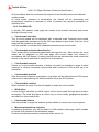
3.5.3.3. AOC REPLY Page
e
The AO
OC REPLY
Y page sha
all contain functions
f
as
a per show
wn in figure
e 8.
Figure
e 8 : AOC REPLY pa
age
The RE
EPLY butto
on from the
e AOC LOG
G page shall select this page.
The selection of any
a of thosse messag
ges shall pe
ermit the IM
MPENDING
G MESSAGES
Window
w to come up for man
naging the
e appropria
ate answer.
The Do
ownlink me
essage desscription sh
hall be disp
played entirely.
Page 20 of 102
2
Turkish Airlines
A320 Full Flight Simulator Technical Specification
3.5.4. Messages Modification
A software utility shall be provided to create/modify AOC message. The message
shall be extracted from the software diskette referenced in EALEQGEN (Refer to
SUMMARY)
3.6. WEATHER RADAR
The weather radar system shall be fully simulated and fully correlated with other
systems such as visual, sound, motion and air data effects.
3.6.1. Ground Mapping Function
The ground mapping function shall be available for airports selected with full EGPWS
correlation (refer to paragraph 3.3.1).
3.6.2. Cloud Model Definition
10 cloud models, including a vertical profile to simulate antenna tilt effect, shall be
provided. (Refer to following array).Some of these cloud models shall be made of
multiple cells.
NB
Cloud Models
1
2
3
4
5
6
7
8
9
10
STORM 1
STORM 2
STORM 3
COLD FRONT 1
COLD FRONT 2
SHOWERS 1
SQUALLS
SNOW
RAIN
STORM 4
Thickness
(TBC)
18 000 ft
42 000 ft
35 000 ft
31 000 ft
20 000 ft
16 000 ft
18 000 ft
16 000 ft
12 000 ft
20 000 ft
Width (TBC)
150 X 150 NM
50 X 50 NM
100 X 100 NM
150 X 150 NM
50 X50 NM
50 X50 NM
100 X 100 NM
100 X 100 NM
50 X50 NM
100 X 100 NM
Type of cloud
Rain and Lightning
Rain and Lightning
Rain and Lightning
Rain
Rain
Rain
Hail
Snow
Rain
Rain and Lightning
3.6.3. Cloud Model Modification
A software utility shall be provided to allow modification in width, thickness and
intensity of each individual cloud model.
3.6.4. Cloud Model Effects
Following cloud model effects shall be simulated:
• Realistic 3D visual representation with full correlation with ND radar image,
• Visibility linked to cloud models and special visual effects such as thunder, rain,
lightning,
• Motion turbulence,
• Realistic wind parameters display on ND (Direction/Speed)
• Environmental sound, (lightning sound which may be heard at high altitudes and
the high speeds shall be realistic as on ground lightning sound and in air sound
differs)
• Perturbations in communications.
Page 21 of 102
Turkish Airlines
A320 Full Flight Simulator Technical Specification
All these effects shall be correlated with respect to the aircraft position and selected
clouds models.
At cloud model activation or deactivation, the effects will be dynamically and
progressively inserted or removed in order to prevent any spurious perception to
operating crew.
3.6.5. Link With IOS
A specific IOS weather radar page will enable cloud models selection and control
through following icons:
• Cloud model selection
The 10 cloud models will be displayed with a reduced scale. Selected cloud model
shall be graphically represented on the IOS map display in grey scale. Only one cloud
model will be selected at the same time.
It will be possible to activate both windshear/microburst and cloud model.
• Cloud models activation/deactivation
Cloud model will be activated or deactivated through this icon. When active, the cloud
model will be displayed on IOS map page with correct shape and colours in
accordance with ND display. Pressing same button de-activates the cloud model that
returns to the same state than it was prior to its activation.
• Cloud models removal
Further to a cloud model selection, a button key shall be available on page to allow
instructor to remove completely cloud model and its effects in IOS as well as in the
simulation.
• Cloud models position
After cloud model selection or activation, its position will be determined on IOS map by
a direct touch repositioning. Its default position will be the A/C position.
• Cloud models rotation
When selected, an arrow in a dial will enable to rotate the cloud model.
• Wind effect
A wind function will allow or inhibit motion of the cloud model through wind direction
and speed. The wind shall have an effect only on cloud model geographical position
and shall not effect wind profile.
• Cloud model effects
It will be possible to suppress weather system effects on motion and sound system.
• Microburst/windshear selection
A predictive windshear icon will be added on IOS weather radar page, which enables
to access IOS microburst and windshear pages.
Predictive windshear has been mentioned under section 4
Page 22 of 102
Turkish Airlines
A320 Full Flight Simulator Technical Specification
3.7. TCAS
The TCAS simulation shall provide a full correlation with visual, sound, IOS and
environment systems.
TCAS II Change 7 simulation shall have the following features:
• All advisories shall be fully implemented with intruder carrying mode A, mode C,
mode S transponder.
• Instructor shall be able to select each possible corrective RA, Preventative RA,
Proximate Traffic and TA Scenarios individually.
• According to the selected scenario, Intruder shall manoeuvre to keep its
position against the own aircraft to complete selected mission.
• RA and TA scenario selected the intruder shall track own aircraft. When
proximate traffic selected the intruder shall not track the own aircraft.
• There shall be sufficient number of scenarios to cover all the TCAS aural
messages.
• There shall be multiple aircraft threats.
• TCAS simulation shall be integrated with visual traffic.
• Threat(s) shall also be visible on the IOS map screen
3.7.1. TCAS Environment
3.7.1.1. TCAS airport traffic
This shall represent a realistic traffic environment around any airport. It shall consist of
up to 10 aircraft flying realistic approaches and departure routes and holding patterns.
Page 23 of 102
Turkish Airlines
A320 Full Flight Simulator Technical Specification
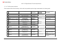
3.7.1.2. TCAS scenarios definition
Each scenario shall include intruder(s), which shall have predefined path and type as described in the following table.
TYPE
IOS page title
INTRUDER
TCAS TYPE
INITIAL
INTRUDER
POSITION
ACTION REQUIRED BY
THE CREW
NON-ADVISORIES TRAFFIC
PROXIMATE TRAFFIC
Mode C
Same level-Right
No action needed
SAME LEVEL-RIGHT
transponder
TRAFFIC ADVISORIES
2 Traffic Advisory (no Altitude
TA NO ALTITUDE DATA
Mode A
Above-left
No action needed
Data)
ABOVE –LEFT
transponder
3 Traffic Adivisory (no Altitude
TA + CONFLICT
Mode A
Forward-same level Action required
Data and potential collision)
NO ALTITUDE DATA
transponder
FORWARD-SAME LEVEL
4 Traffic Adivisory (no Bearing
TA NO BEARING DATA
Mode C
Below-left
No action needed
Data)
BELOW-LEFT
transponder
5 Traffic Advisory
TA
Mode C/Mode S
Aft-below
No action needed
AFT-BELOW
transponder
RESOLUTION ADVISORIES
6 Preventive Resolution
RA PREVENTIVE
Mode C/Mode S
Forward-same level Maintain current flight path
Advisory
(MAINTAIN V/S)
transponder
FORWARD-SAME LEVEL
*6-This scenario includes two intruders coming from the same position but with different altitudes : one above and the other one below the A/C
7 Corrective Resolution
RA CORRECTIVE
Mode C/Mode S
Same level-right
Climb or descent
Advisory
(CHANGE V/S)
transponder
SAME LEVEL-RIGHT
8 Enhanced Resolution
RA ENHANCED
Mode C/Mode S
Below-left
Climb or descent then
Advisory
BELOW-LEFT
transponder
increase rate of climb or
descent
9 Reversal Resolution
RA REVERSAL
Mode C/Mode S
Forward-below
Climb or descent then
Advisory
(V/S REVERSED)
transponder
reverse direction of climb
FORWARD-BELOW
or descent
1
Proximate traffic
Page 24 of 102
Turkish Airlines
A320 Full Flight Simulator Technical Specification
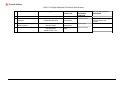
TYPE
10
Crossing Resolution
Advisory
11
Resolution Advisory (No
Bearing Data)
Conflict-No warning
12
IOS page title
INTRUDER
TCAS TYPE
INITIAL
INTRUDER
POSITION
ACTION REQUIRED BY
THE CREW
RA CROSSING FLIGHT PATH
FORWARD-BELOW
Mode C/Mode S
transponder
Forward-below
RA NO BEARING DATA
ABOVE-RIGHT
CONFLICT
NO WARNING
SAME LEVEL-LEFT
Mode C
transponder
No transponder
fitted
Above-right
Climb or descent through
the flight path of the
intruder
Action required
Same level-left
Maintain a visual check
Page 25 of 102
Turkish Airlines
A320 Full Flight Simulator Technical Specification
3.7.2. Link with IOS
Specific IOS TCAS page shall enable scenario selection, control and modification of
TCAS airport traffic:
• 12 scenario buttons shall be displayed (refer to paragraph 3.7.1.2),
- a scenario shall be immediately activated or deactivated after pressing the
corresponding button.,
- The scenario deactivation shall remove immediately all effects linked to this
scenario.
- only one scenario shall be selected at the same time,
• Intruders shall be graphically represented on the IOS MAP with the same shape and
colours than on ND,
• Collision time shall be displayed on IOS TCAS page and collision time shall not
exceed 90 seconds.
• An “AIRPORT TRAFFIC” button shall be displayed to control a popup menu
allowing the following choices:
- Heavy traffic (10 aircraft),
- Medium traffic (5 aircraft),
- Light traffic (1 aircraft),
- Off (No aircraft).
3.7.3. Scenario and Airport Traffic Modification
A user friendly software utility shall be provided to create/modify TCAS scenario.
3.8. SYSTEM WITH PARTIAL SIMULATION SPECIFIC REQUIREMENTS
The following systems shall be simulated according to the following restrictions.
3.8.1. External Lighting
External lighting, such as navigational lights, landing lights, shall be simulated in relation
to electrical loads and visual display when these are significant.
Controls shall be located and shall function as in the aircraft.
3.8.2. Air Conditioning And Cabin Pressurisation
The aircraft air conditioning and cabin pressurisation systems shall be simulated to the
extent that flight compartment control and indicators function as per Aircraft Data.
The simulated air conditioning and cabin pressurisation systems shall not have effect on
the FS flight compartment.
3.8.3. Electrical Power
The installation of electrical outlets (one outlet dedicated to the Pilot, the other to the
First officer) in cabin shall be submitted to following considerations:
• Power supply shall be let to the end user choice and shall offer typical safety
features (limitation of the available power to the lowest value, filter incorporated at
level of outlet, electro-magnetic compliance with the on-board equipment).
• The plugs shall be permanently supplied after the simulator initialisation.
3.8.4. Oxygen System (crew and passengers)
The seller shall simulate the crew & passengers Oxygen System.
THY shall provide breathable air supply source.
Page 26 of 102
Turkish Airlines
A320 Full Flight Simulator Technical Specification
The controls shall have action on crew airflow and indicator in accordance with normal
and emergency usage.
ECAM shall reflect the IOS settings.
Passenger oxygen system shall be simulated to extend of appropriate cockpit
indications and controls in accordance with aircraft data.
3.8.5. Communication Systems
3.8.5.1. General communication
Two-way communications between instructor and each crewmember shall be possible
by means of the A/C and IOS ACPs (refer to paragraph 7.2.4.2) and Communication
Panel (refer to paragraph 7.2.6.8)
Typical background radio noise control shall be provided at the Instructor Operating Station.
This background noise shall be able to be muted or the user shall be able to tune its level.
CIDS shall be simulated to the extent that related controls, visual and audio indications
and speakers are operable within the flight compartment.
3.8.5.2. CIDS : Cabin Ready
The Cabin Ready function shall simulate the actions on CABIN READY Pushbutton
situated on the Forward Attendant Panel.
It shall be simulated to cover the two following modes in accordance with the CIDS
logic.
3.8.5.2.1. Link with IOS
The CABIN READY memo shall be simulated according to IOS (refer to
paragraph7.3.4.10) selection through two control buttons:
• AUTO/MANUAL
• ON/OFF
3.8.5.2.1.1. Automatic mode (Default mode)
The CABIN READY memo shall be automatically displayed:
• 5 minutes after door closed and slides armed. This delay shall be applied only after
Gate Parking repositioning.
• During Approach and Landing phases, The CABIN READY memo shall be
displayed after Flaps extended to 2 and gear down selected..
3.8.5.2.1.2. Manual mode
After selection of the MANUAL mode, the “ON/OFF” button shall become active (greyed
in AUTO mode) and emulate the activation forward cabin ready control by the flight
attendance.
3.8.5.2.1.3. Cockpit Voice Recorder.
Cockpit Voice recorder panel shall be installed as in the aircraft. Volume level indication
and erase logic shall be simulated.
Page 27 of 102
Turkish Airlines
A320 Full Flight Simulator Technical Specification
3.8.6. Flight Recorder System
The flight recorder panel shall be installed as in the aircraft. Clock and logic sequence
shall be simulated.
3.8.7. Window Heat
The window heating shall be simulated only to the extent that the controls and indicators
operate as in the actual aircraft.
3.8.8. Circuit Breakers
All the circuit breakers shall be fully simulated.
3.8.9. Windscreen Wipers And Rain Repellent System
The windscreen wipers shall be simulated only to the extent that the control switches
are active on visual displays and sound system under instructor weather condition
control.
The aircraft rain repellent system control shall be installed as applicable to the cockpit.
Operation of the rain repellent system shall not be simulated.
3.8.10. Sensors
Due to the use of A/C equipment simulation (refer to paragraph 3.1), the Seller shall
take a special attention to this part of simulation.
In particular, sensors shall be fully simulated, including errors and deviations, each time
that these effects affect equipment behaviour.
Consequently, simulated equipment shall take into account these sensor errors and
compute the same correction as the real ones whenever necessary.
Relative sensor position shall also be taken into account to improve computation
results.
3.9. MALFUNCTIONS
The Malfunctions list is defined within the Airbus document “EAMLFFFS”. For each
malfunction, causes and consequences are detailed.
The IOS malfunction pages shall be customised according to A/C version selected at
FFS launching.
In case of Data Package evolution during the project, THY reserves the right to update
the above document accordingly.
3.10. OEB IMPLEMENTATION UTILITY
•
•
•
The Seller shall implement an OEB reminder function within the FWS, with the
following requirements:
The Seller shall supply an offline tool and procedures to define and update an OEB
flag database. This database shall contain the list of ECAM message(s), for which
OEB is (are) active, and applicability of the OEB to procedure and/or status
information.
This modification of the OEB flag database shall carried engineering-type
population, not by trainees or instructors. Therefore a simple text file type interface
is sufficient.
The identification of the applicable ECAM message in the OEB flag database shall
be done using standard ATA reference (FWC message ident), so that no internal
knowledge of the implementation of the FWC is required by the end-user.
Page 28 of 102
Turkish Airlines
A320 Full Flight Simulator Technical Specification
4. ENVIRONMENT SIMULATION
4.1. ATMOSPHERE
The IOS shall be able to allow at the beginning of each flight the setting of the weather
situations of the departure, destination and alternate airports, with a smooth transition of the
visual weather situation as well as enroute weather parameters.
The following meteorological items:
- Wind
- Visibility
- Clouds
- Temperature
- Dew point
- Altimeter setting
- Windshear
- Microburst
- Thunderstorm and lightning
- Variable turbulence
- Icing
- Low visibility
- Rain shafts
- Hail
Shall be provided in that sequence.
The value and the selection of these items shall be correlated for having a realistic
meteorological situation. They shall produce accurate effects on A/C path.
4.1.1. Winds And Turbulence
4.1.1.1. Windshear and microburst
Representative modelling of three dimensional Windshear dynamics based on aircraft
related data to comply with the authorities official documents referenced in the chapter 1
and the Pilot Windshear guide AC0054 shall be provided. Among the available
windshear scenarios, which can be detected by Predictive Windshear System, will be
marked as ‘’suitable for Predictive Windshear Training’’ .
At least three separate windshear scenario shall be provided for predictive windshear
system training at :
•
Prior V1
•
After Take Off
•
Approach
The following windshears shall be simulated, correlated with Weather Radar simulation
and selectable from the IOS:
•
•
•
FAA wind fields 4, 6, 7, 8, 9, and 10, as defined in FAA AC 120-41.
Seven microburst, of which six microburst shall be based on Royal Aircraft
Establishment models and shall be selected from the IOS (3 in take-off position and
3 in approach position) for each selectable Airport. The seventh Microburst shall be
selectable by Instructor on IOS to fill in required values and the Instructor shall be
capable to be positioning the Microburst by Drag and Drop functionality of IOS.
Refer to following array for microburst information of 6 pre-selected Microburst
based on Royal Aircraft Establishment models.
Page 29 of 102
Turkish Airlines
A320 Full Flight Simulator Technical Specification
Microburst
R Radius (m)
H Height (m)
Max velocity
(knots)
X Lateral distance
to threshold (m)
Y Longitudinal
distance to
threshold (m)
1
1200
350
45
2
1100
550
60
3
1200
300
70
4
1200
550
90
5
1100
300
60
6
1100
550
75
0
0
579
322
0
0
1852
3334
3334
-1852
-5556
-1852
When selecting a microburst, the following variables shall be set to determined values:
• Centre of microburst distance to runway threshold on runway axis.
• Centre of microburst distance to runway threshold on runway across axis.
• Radius of microburst.
• Height of microburst centre above ground level.
• Vortex factor multiplier.
• Surface wind speed.
• Surface wind direction.
All these variables shall be easily and directly modifiable by action through the IOS in
Maintenance mode, and shall be displayed on IOS screen when a windshear or
microburst is selected. (As recommended by authorities).
Its centre will be indicated on IOS map by a dedicated symbol.
4.1.1.2. Wind vector
Wind selection from the Instructor Operating Station shall be available.
Wind speed and direction shall be variable.
A realistic boundary layer effect due to the ground on surface wind shall be simulated.
Wind vector shall be selectable from the IOS at 3 various levels:
• Low level (Approach)
• Intermediate level
• High level (Cruise)
At each level, wind speed and direction shall be modifiable within realistic limits.
Wind vectors shall be interpolated between these levels.
A standard wind gradient shall be proposed as a default selection.
For cruise purposes, wind vectors shall be selectable at various identified positions and
altitudes.
A random function, activated on request, shall be available to set a range of variation
around the average values of wind speed and heading.
4.1.1.3. Turbulence
Turbulence shall be available from the Instructor Operating Station (percentage control).
Page 30 of 102
Turkish Airlines
A320 Full Flight Simulator Technical Specification
A turbulence level between 0 and light turbulence will be set as default. For the realism
of the simulation, when cloud selected and A/C is in cloud, randomised light level
turbulence will be applied automatically.
Dryden turbulence associated with FAA AC 120-41 wind fields shall be simulated.
Free air, low and high frequency turbulence, clear air turbulence (CAT), shall be
simulated. Turbulence level shall depend on wind type selected (surface wind, wind
field, microburst).
Turbulence level between low and 0 shall be set as default during simulation activation
for the realism of the simulation.
4.1.1.4. Effects, selection and logic
Winds and turbulence shall produce appropriate effects on flight path and motion.
Special motion cues due to turbulence shall be simulated.
Wind insertion or modification shall not produce heavy changes but should gradually
increase/decrease on flight path and motion.
Compatibility of winds and turbulence shall comply with the following table:
SURFACE WIND WIND FIELDS MICROBURST TURBULENCE
SURFACE WIND
WIND FIELDS
MICROBURST
TURBULENCE
YES
YES
YES
YES
NO
YES
YES
NO
YES
YES
YES
YES
The last wind type selected shall have priority and eliminate the non-compatible wind
types.
4.1.2. Icing Conditions
Icing conditions shall be selectable from the Instructor Operating Station.
Icing conditions shall produce realistic effects on airframe, engines, probes, aircraft
weight, aerodynamics, depending on operation of de-ice systems.
4.1.3. Temperature And Atmosphere Pressure
Ground level outside air temperature shall be variable from the Instructor Operating
Station. Effects of temperature change on altitude readings shall be simulated.
Ground and sea level barometric pressure shall be variable from the Instructor
Operating Station.
Note: Simulator design shall ensure that computed atmospheric parameters remain at a
realistic value within the whole A/C operation domain (i.e. in flight operation with low
outer temperature on ground).
4.2. RUNWAY
4.2.1. Runway Type
Smooth and bumpy runway types shall be available from the Instructor Operating
Station.
Special motion cues shall be simulated for these runway types.
Page 31 of 102
Turkish Airlines
A320 Full Flight Simulator Technical Specification
4.2.2. Runway Conditions
The runway conditions will be those required by the authorities official documents
(referenced in the chapter 1). They shall be available from IOS.
Representative braking, stopping and directional effects for these runway conditions
shall be simulated. All visually available runway conditions of IG shall be controlled by
IOS.
4.3. TERRAIN PROFILE
Terrain profile shall give a realistic reproduction of the ground altitude variations in the
vicinity of the simulated airports and on runways and taxiways.
There shall be cross talk from visual computer to the host computer to ensure
correlation between environment profile and visual profile.
4.4. SOUND SIMULATION
Sound simulation must meet Level D standard as defined in the Authorities official
documents (referenced in the chapter 1 ).
All necessary tools (for recording and analysing purposes), licenses and
procedures shall be provided to THY.
4.4.1. Sound fidelity
Sound simulation shall be correlated with the whole simulation and shall include all real
cockpit audible sounds. Sound shall be at an appropriate level through adequately
baffled speakers at appropriate locations to give proper directional effect to each source
of significant sound. Particular attention shall be put on environmental sounds with
minimum requirements as level D (refer to chapter 1).
Sound simulation shall correlated with visual cues.
4.4.2. Sound tuning and evolution
Individual volume adjustment shall be possible for each sound (audio warning, sound,
ATIS…) by means of an appropriate Hardware or Software process, without any need
for equipment dismount. The Seller shall provide some sound and voices spares
(minimum 30% of sound system capability, useable without any sound affectation
restriction) and shall ensure that the addition of sounds or voices shall be done along
the sound generation chain through an easy to use procedure. All necessary tools (for
recording and analysing purposes), licenses and procedures shall be provided.
4.4.3. Sound controls
Aircraft systems generated sounds volume shall be always set to nominal value.
Communications sounds volume shall be tuned by cockpit controls.
In the same time, environmental sounds volume shall be controlled through IOS by 2
ways:
Page 32 of 102
Turkish Airlines
A320 Full Flight Simulator Technical Specification
•
•
•
•
Variable control: 80% volume position shall correspond to the nominal level
of the simulated sound.
Discrete control: global mute function Specific functions:
During freeze: only environmental sounds shall be muted
During repositioning: all sounds shall be muted.
4.4.4. Flight compartment ambient noise level
The acceptable acoustic noise level in the crew and instructor areas, as measured near
the head level of the occupants when seated at their positions, shall not exceed 55dB
NR according to standard ISO R1996, checked when sound is switched off, FFS
entrance door is closed, and FFS room noise level does not exceed 55 dB NR.
Even in FFS vibration conditions (rolling on runway, buffet...), no noise shall be
generated by the crew compartment structure (doors, sheet-iron, motion jacks, .).
•
•
•
•
•
•
•
•
•
•
•
•
4.4.5. Aircraft And Environmental Sounds
Particular attention shall be put on the following noises:
Ground power connected and electronic equipment cooling on.
Engine Start (There shall be a realistic noise level when all cabin and cockpit
doors are closed.)
Power plant (engine whine, air noise and thrust reverse operation).
Aerodynamic noise and airframe sound (including wind noises, gear and door
operation).
Landing gear actuation noises.
Runway effects (including individual gear touch down and bounce).
Air conditioning airflow.
Cockpit equipment background noise.
Precipitation noise.
Thunder noise. (Shall be realistic according to the aircraft configuration. Eg:
At a speed of .80 Mach the sound cannot be same as on ground.)
Wipers noise.
Crash noise.
4.4.6. Warning Sounds And Voices
Similarly audible cockpit warnings such as horns, bells, etc. shall be simulated
using actual aircraft components or equivalent to assure faithful reproduction of
the individual sound of these devices.
4.5. NAVIGATION AND COMMUNICATION ENVIRONMENT SIMULATION
4.5.1. Navaids Data-base
The FS database shall be worldwide.
It will be created with a Navaids Database using ARINC 424-xx format. This format shall
be defined upon contract signature and by default it shall be the format valid at that
time. Since THY uses military airfields for domestic flights as well, military
airfields used for commercial operations in Turkey should also be added into the
navigation database from other sources.
Page 33 of 102
Turkish Airlines
A320 Full Flight Simulator Technical Specification
All parameters defined by the ARINC 424-xx format shall be taken in account to provide
a realistic simulation of the navaids.
4.5.2. Navaids Processing
It shall be possible to process, at any time, any Navaid when the A/C is within range.
On some airport landing strips, there are two runways with the same ILS/DME
frequency. In that case, during approach, the ILS/DME of the opposite runway shall be
automatically failed (without any action on IOS).
In the same way, the recovery of this failed ILS/DME shall be automatic as soon as an
approach is performed on its runway.
A magnetic variation calculation program shall be used for all points of the earth.
4.5.3. Navaids Failure
It shall be possible to fail all or part of multiple installations.
The name and type of any failed navaid shall appear on the Instructor Operating
Station.
A list of airport in use navaids shall be proposed by default when navaid failure function
is selected.
4.5.4. Communication Stations
Seller shall provide realistic ATC Radio Chatter in cockpit:
Radio Chatter shall consist of typical communication exchanges between ATC and all
aircraft. The instructor will do ATC traffic simulation only for the simulated aircraft.
• The communication stations shall be automatically activated in accordance with the
A/C position and the selected frequency.
• The Radio Chatter shall be specific to the above airports.
• Seller shall provide a user-friendly means to alleviate the Instructor workload :
− By proposing on IOS a predefined list of typical ATC messages.
These messages will be inserted within the frame of overall ATC messages
when selected by the Instructor.
− The Instructor shall be able to communicate without any need of frequency
selection.
− The instructor will also be allowed to communicate directly through the ACP.
• Seller shall take special care in voice quality simulation.
• An user-friendly utility shall be provided to add/modify/delete predefined messages.
4.5.5. RT and ATC Radio Chatter
RT Chatter and ATC communications shall be simulated in accordance with IATA document
“Simulated Air and Ground Traffic Environment for Flight Training” level II.
Seller shall provide realistic ATC Radio Chatter in cockpit:
•
Radio Chatter shall consist of typical communication exchanges between ATC
and all aircraft. The instructor will do ATC traffic simulation only for the simulated
aircraft.
•
The communication stations shall be automatically activated in accordance with
the A/C position and the selected frequency.
The Seller shall provide a user-friendly means to alleviate the Instructor workload:
Page 34 of 102
Turkish Airlines
A320 Full Flight Simulator Technical Specification
•
•
•
•
By proposing on IOS a predefined list of typical ATC messages. These messages
will be inserted within the frame of overall ATC messages when selected by the
Instructor.
The Instructor shall be able to communicate without any need of frequency
selection. The instructor will also be allowed to communicate directly through the
ACP.
Seller shall take special care in voice quality simulation.
An user-friendly utility shall be provided to add/modify/delete predefined messages.
4.5.6. ATIS Simulation
4.5.6.1. General performance
An ATIS simulation system shall be provided. It shall be possible to associate ATIS
facility with communication and navigation system.
All ATIS broadcast parameters shall be able to be initialised individually for any preselected Airport and runway.
Without initialisation, the messages shall be updated automatically in accordance with
the meteorological and visual conditions, the runway status and the radio aids status
selected at the Instructor Operating Station.
The frame of the messages shall be in accordance with the geographical position of the
airport. For that reason, American and European ATIS messages shall be provided.
4.5.6.2. Links with IOS
The ATIS message program page shall allow the instructor to select by ICAO the
desired airport. All ATIS message parameters shall be controllable on that page.
This page shall include the following 4 functions:
• ATIS OVERRIDE: validation of ATIS parameter set.
• ATIS TO CURRENT WHEATHER: copy of weather conditions into ATIS
parameters.
• ATIS NOT AVAILABLE: When selected, this message will be broadcast instead of
the ATIS information.
Supplemental messages to the ATIS broadcast shall be provided and selectable by the
instructor.
A status page shall be displayed upon request to list all the pre-programmed ATIS
messages.
4.5.6.3. ATIS message modification
A software utility for ATIS messages modifications shall be provided. Male or female
voice broadcasting will be randomly selectable.
Page 35 of 102
Turkish Airlines
A320 Full Flight Simulator Technical Specification
4.6. SMOKE GENERATION
Subject to the instructor selection, smoke shall be introduced into the cockpit in
conjunction with a simulated fire.
Two smoke sources shall be simulated and selectable independently from the Instructor
station:
• Air conditioning smoke
• Electrical smoke
Smoke shall be non-toxic and harmless to personal and equipment. Realistic aircraft
smoke sources shall be provided in relation with malfunction definition.
Preparation phase: smoke system shall be available in less than 5 minutes.
A "smoke available" indicator shall be provided at the Instructor Operation Station. The
instructor shall have the possibility to stop smoke generation at any time, even if
malfunction is still inserted.A message shall be displayed on the integrated display
outside the FFS during smoke exercise.
The smoke generator agent shall be be non-toxic and harmless to personal equipment.
.
The smoke shall be dissipated from the cockpit rapidly by cockpit exhaust fans, outside
the building.This smoke evacuation system shall not generate audible noise level in the
cockpit able to disturb the training.
The visual mirror compartment shall be smoke proof in order to avoid any cockpit
smoke propagation and visual display quality degradation.
The exhaust fans shall stop (if running) when smoke is generated.
For safety, hot pieces of smoke generator shall be clearly indicated. Internal
temperature of oil boiler shall be indicated.
An off-line command of the smoke generator shall be provided.
Seller shall provide a suitable device to avoid cockpit smoke generation from triggering
the FS premises smoke detection system (Refer to paragraph 13.4.4)
Page 36 of 102
Turkish Airlines
A320 Full Flight Simulator Technical Specification
5. TOLERANCES
Final acceptance tolerances for the objective tests must meet the most restrictive
tolerances defined in the list of tests which are included in the authorities official
documents (referenced in the chapter 1).
Page 37 of 102
Turkish Airlines
A320 Full Flight Simulator Technical Specification
6. FLIGHT COMPARTMENT
6.1. GENERAL
The interior of the simulator cockpit shall conform to the full-scale replica of the aircraft
cockpit. Aircraft cockpit shall be simulated from the bulkhead forward of the rudder
pedals to the bulkhead forward of the rest compartment.
In the simulator cockpit Seller shall integrate all A/C Equipment and A/C Parts according
to Airbus Standard 1.6 DPE (refer to Summary) and to the simulation requirements
(refer to paragraph 3).
Seller shall inform in detail how much of the cockpit panels, instruments and
components will be provided from Airbus, how much of these items will be replicated or
simulated (rehosted/retargeted etc) by the manufacturer. List of all these items will be
given by part numbers, description and quantities by the Full Flight Simulator parts
catalogue supplied by the technical specification where the design and functionality of
the device explained in detail.
Seller shall propose a means to easily verify that the replication of the cockpit
compartment dimensions and layout of the A/C are in accordance with Airbus
Standards. This process of verification of the simulator cockpit versus to the A/C cockpit
dimensions shall be demonstrated during in plant Acceptance.
In particular, THY shall be allowed to measure the windshield and crew seats position,
the pilots eye position (XYZ co-ordinates, and angles), the Visual System Field of View
and cut-off angles.
All control levers in the flight compartment shall be provided and shall move through the
same range of motion as is available in the aircraft, requiring the same force to move
them as required in the aircraft. Similarly, all instruments, indicators, push buttons and
switches in the compartment shall be operable.
The flight compartment shall be airtight enough to comply with the fire suppression
system requirements.
6.2. FLIGHT COMPARTMENT GENERAL ARRANGEMENT
The Flight compartment shall include:
• The crew compartment with Scratch Resistant cockpit windows,
• Instructor operating station.
• Three movable and adjustable SEATS, one for the instructor and two for the
observers.
• A movable rear panel with the folding seat.
• A location for emergency equipment shall be mutually agreed between THY and the
seller.
• The rear panel shall generate no vibration or noise and it shall be equipped with
mechanical interlocks and sensors to forbid motion when it's not in opened or closed
position.
6.3. LIGHTING
Beside cockpit aircraft lighting, enough lighting shall be provided to lighten the cockpit.
In case of main power failure, an emergency lighting shall be provided for at least 15
minutes.
The light control shall be located both at the entrance door and at the IOS.
Technical premises shall be lit for maintenance purpose.
Maintenance lighting shall be provided underneath the flight compartment area.
Page 38 of 102
Turkish Airlines
A320 Full Flight Simulator Technical Specification
All equipment cabinets lighting shall be provided with an on/off control.
6.4. VENTILATION AND AIR-CONDITIONING
The flight compartment shall be air-conditioned. A thermostatic control shall regulate the
temperature inside the flight compartment in Celsius.
Seller shall provide and install an Air Conditioning Unit (ACU). (Chilled water
dependent)
Seller shall ensure that the selected ACU model have technical support in terms of
Spare Parts and Maintenance in Turkey.
The ACU shall include an air-processing unit connected to a distribution circuit by
means of two separate groups of flexible ducts. The air-processing unit shall provide
cold air for instruments and electronic equipment, hot air and cold air for the flight
compartment.
The air distribution circuit shall not be the aircraft circuit, as this one can only give a
good air conditioning in the real aircraft ventilation conditions.
The ACU shall enable the air in the flight compartment to be changed at least once
every two minutes. The flight compartment ventilation shall also be filtered.
Instructor shall be able to set the flight compartment temperature between 18° C and
22°C by means of a thermostat located in the flight compartment. These conditions will
be held with all seats occupied in the flight compartment, with the entrance door closed
and all covers fitted.
Moisture from condensation in the FS air conditioning system shall be trapped and
contained.
Ventilation: The heat dissipation ratio shall include the visual system equipment(s) in
the flight compartment and the visual projector.
The ACU distribution shall include cold air for visual projector assembly (1 duct per
projector assembly).
6.5. INTERIOR NOISE LEVEL
The acceptable acoustic noise level in the crew and instructor areas, as measured near
the head level of the occupants when seated at their positions, shall not exceed 55dB
NR according to standard ISO R1996, checked when sound is switched off, FS
entrance door is closed, and FS room noise level does not exceed 55 dB NR. (With A/C
unit running)
When FS in vibration conditions (rolling on runway, buffet...), no noise shall be
generated by the crew compartment structure (doors, sheet-iron...).
6.6. TELEPHONE AND BOOM SET
6.6.1. Telephone
A telephone system shall be provided in order to permit direct communication between
the following locations:
Page 39 of 102
Turkish Airlines
A320 Full Flight Simulator Technical Specification
•
•
•
•
•
Computer room,
Motion cabinet
Maintenance Crew Room
Flight compartment (IOS)
The manufacturer shall ensure that telephone set installed is fully compliant with
vendor's company standard installation.
6.6.2. Boom Set
Maintenance BOOM SET type phone shall be provided on 5 locations:
• Inside flight compartment (near pilot seats)
• On top of flight compartment (2 places near display units/or projectors),
• Computer room near visual cabinets.
• Underneath the flight compartment.
6.7. WALKWAY PLATFORM DRAWBRIDGE
Seller shall install a safety gate equipped with suitable safety interlocks to access the
Flight compartment from the drawbridge.
The safety gate extreme breadth shall allow for a passage as wide as the drawbridge
(Passage shall be at least 75 cm wide).
Seller design shall ensure the alignment and same extreme breadth of the entrance
door, the safety gate and the drawbridge.
Seller shall install a walkway platform allowing for an easy and safe access to the
external side of interface cabinets and to the Visual system (Projectors platform and
mirror compartment).
In particular the Seller shall install all necessary handrail protection on the access
ladder and the projector platform.
The projector platform access shall be coupled with the Motion System interlock that
when area used for maintenance, resetting required to verify the safety of the area..
.
When the FS motion system comes to its normal rest position, the crew shall enter or
exit via a drawbridge, which shall automatically extend towards the entry platform.
(Drawbridge slope shall not exceed 2 %). The guard-rail of the drawbridge shall be
articulated in order to take a minimum space when the drawbridge is raised.
Should the motion system comes to rest in an unusual position or in case of emergency
situation, the crew shall be able to leave the FS by means of knot ropes or rope ladders
from the rear door of the flight compartment or a separate emergency exit. (Refer to
paragraph 13.4.2)
The entrance door of the flight compartment shall be fitted with a shuttered drawbridge
observation window. Plus a view peephole.
Dimensioned drawings of flight compartment, platform, total FS envelop, drawbridge,
gate etc ...must be provided by the Seller prior to contract signature.
Page 40 of 102
Turkish Airlines
A320 Full Flight Simulator Technical Specification
International safety regulations shall be respected for emergency exit (Refer to
paragraph 13.4.2).
In particular the drawbridge shall be equipped with 2 warning lights one must be visible
from the walkway platform the other one must be visible from the base of the FS.( refer
to paragraph 10.5 )
On normal drawbridge and motion operation , lighting and audio warning must be
provided.
Lighting and audible warning shall be provided during engagement and disengagement
of both motion and drawbridge system.
6.8. MISCELLANEOUS
•
•
•
Coat space with minimum 5 coat hooks shall be provided inside the flight
compartment.
Stowage facilities shall be provided for:
− 5 brief-cases and manuals
− Visual system remote control box (if necessary)
− Antiseptic spray holder and antiseptic paper supply device for oxygen masks.
− Kleenex" type papers container device.
− Dustbin: shall be provided at a convenient location
These stowage facilities shall be able to withstand the maximum accelerations and
vibrations produced by the motion system without dislodging or causing damage to
their content.
Service outlets : Sufficient service outlets shall be provided in all simulator area:
each cabinet, under platform, visual platform, computer area, HPU…
Page 41 of 102
Turkish Airlines
A320 Full Flight Simulator Technical Specification
7. INSTRUCTOR OPERATING STATION (IOS)
7.1. GENERAL
As a Man Machine Interface IOS shall comply with the general requirements below:.
• It shall be designed to be user friendly and self explanatory to the non-familiar
Instructor.
• Allow the Instructor to operate in a fully forward style (Forward Facing concept
(FFIOS)) and capable of giving him freedom to move in the cockpit should he desire
with all the controls within his reach.
• The IOS environment shall conform to basic instructor operation needs in terms of
ergonomics (accessibility to different devices, lighting, visibility of crew and cockpit,
comfort of use, etc…)
• The access to crew seats must be easy and simple. The instructor must have an
easy access to central pedestal
• The IOS shall not interfere with a normal use of the complete aircraft cockpit
configuration.
• IOS pages shall be customised depending on A/C versions, engine versions, and
units more generally any model customisation. Limits and units will be based on the
model configuration loaded.
• Safety: the whole design of IOS and aft compartment shall comply with the general
rules of Health and Safety (refer to paragraph 13.4).
• The AFT cabin layout, including instructor seat’s configuration one IOS Screen on
each armrest and rails location shall be defined and agreed between THY and Seller
during design reviews at the beginning of the project.
Seller shall present at Preliminary and Detailed Reviews a general 3D mocked up
layout to THY for agreement.
7.2. INSTRUCTOR STATION LAYOUT
7.2.1. Hadrware Layout
The layout of IOS shall be oriented towards Forward Facing concept (FFIOS), which means
that all the important IOS functions shall be controlled by the instructor while seated on the
IOS seat whatever its position in the cabin. The final configuration of IOS seat and the aft
cabin layout including:
•
•
•
•
IOS controls means (screens and buttons)
Ergonomics issues
Seat’s displacement capabilities in the different axis
Miscellaneous equipment (such as ACP, lights control switches, telephone, book
stowage and working surface) shall be defined after having reviewed the different
Seller’s proposed solutions and mutually agreed at Design Review.
Page 42 of 102
Turkish Airlines
A320 Full Flight Simulator Technical Specification
7.2.2. Screens.
•
•
•
•
•
•
•
IOS will have set of two (2) high resolution full colour flat touch screens.
Their dimension and image quality must be such that simultaneous text and
graphics shall be clearly legible from Instructor working distances even if tilted. (No
less than 15 inches)
They shall be tilting and swivelling.
The touch surface technology shall be hard surface touch sensitive device.
It shall also accurate enough to ensure the best correlation between the touch
surface and the screen display.
This correlation shall be reliable enough in order to prevent frequent calibration .
In the case the calibration is eventually needed it shall be easily operated through a
dedicated page on maintenance mode.
Both screens shall have adjustable contrast and brightness controls capable of
completely
dimming
the
displayed
image.
Automatic screen saver function shall be provided.
Both screens shall be able to work in total independent operation: they shall have
the same capabilities, (refer to paragraph 7.2.6) and it shall be possible to display
the same page on both screens.
7.2.3. FFIOS Seat
Seller shall provide 1 (one) instructor and 2 (two) observer seats as defined in the
following.
The seats shall be fitted with interchangeable seat covers and suitable seat belts.
7.2.3.1. Instructor Seat:
The design of the seats shall comply with the general requirements stated in paragraph
7.1, in particular:
• The seat position shall be able to:
− Move along the rails fitted into the floor
− Move vertically
− Swivel
− Recline backrest
− Seat’s pan adjustment
• It shall be electrically motorised along the vertical (up/down) and horizontal (aft/fwd)
axis.
• Range of movements of the seat shall allow the instructor to have a proper view on
crew's operations and cockpit flight instruments.
• The seat shall also be fitted with:
− 2 writing surfaces with raised edges, one at each side of the seat. They shall be
at least A4 format. They shall be fitted with penholders and a recess for small
objects (spectacles).
− 2 book storage areas, one at each side of the seat. They shall be large and
deep enough to allow the instructor to stow FCOM sized manual as well as A4
student files.
− 1 telephone storage under the left armrest (refer to paragraph 6.6).
− Suitable
reading
lights
adjustable
in
position
and
brightness.
Page 43 of 102
Turkish Airlines
A320 Full Flight Simulator Technical Specification
7.2.3.2. Observer Seats:
Two observer seats shall be provided with upholstered and adjustable armrests and
movable on rails fitted into the floor with the same displacement capability as
instructor's one.
Their track shall comply with the general ergonomic requirements and allow the
observers to the best field of view considering the primary objectives for the Instructor.
7.2.4. Pushbuttons, Panels and Controls Located on the Instructor Seat
Following devices shall be located on the Forward Faced IOS seat at a convenient
position so as to be easily accessible by the instructor in accordance with overall
objectives in terms of ergonomics.
Hardware Push Buttons shall be located on the armrests and shall be designed in order
to prevent inadvertent selections.
Integrated lighting logic for the push buttons shall be designed in order to display the
status of the process at any time.
7.2.4.1. Hardware Push Buttons Panels
Hardware push buttons shall be provided in order to control:
• The most frequently used at least 12 functions of the IOS.THY will provide the list of
them at the time of the related freeze date.
• Control loading system
• Motion and draw bridge system
7.2.4.2. Simulator and Motion&C/L Emergency Stop Buttons:
Both emergency stop buttons shall be located at a convenient position so as to prevent
inadvertent selection
• Motion&C/L Emergency stop button (refer to functional description paragraph 10.5
SAFETY REQUIREMENTS).
• One simulator emergency stop button (refer to functional description paragraph
13.4.3 Emergency Power Off).
7.2.4.3. A/C Communication Panel
An ACP box will be used for communication between instructor and pilots. This shall
include a boom set and a handmic with facility (sockets) located at a convenient position
of Instructor Seat.
7.2.4.4. Sound Control
A/C cockpit sound volume shall be controlled by both discrete and variable controls
(refer to paragraph 4.4).
7.2.4.5. Overhead Light Switch
The Overhead light switch acts as a two-way switch with another one located near the
entrance door. These switches control the rear compartment lights.
Page 44 of 102
Turkish Airlines
A320 Full Flight Simulator Technical Specification
7.2.4.6. Lighting Controls
For Instructor's working table a fix reading light that is flexible and intensity adjustable
shall be provided. Light colouring shall be selectable between red and white.
7.2.4.7. Telephone
It shall be preferentially located under the left armrest (refer to paragraph 6.6 ).
7.2.4.8. Clock with stop watch
7.2.4.9. Controls for Monitor Brightness and Contrast
7.2.5. Controls not Located on the Instructor Seat.
7.2.5.1. Flight Compartment Air Conditioning Control
7.2.5.2. Remote Control Box for IOS
A remote control box to be used by the instructor when seated in pilot seats shall be
provided. The receiving set shall be included in the IOS. There shall be a limited
number of functions available
Wireless data link is preferred; in case of hardware wiring the cable length shall be long
enough to allow operation from Crew seats.
The RCB push buttons surface shall be concave in order to permit easy use when in
darkness. They shall be real push buttons with integrated lighting.
First action on push button shall set the function, second action shall reset the function,
except for "Eng Start" (not applicable).
Brightness shall be controllable. Functions and arrangement are described in figure
below.
BRIGHTNESS
T/O
TOTAL FREEZE
CAVOK
ENG 1 FAIL
FINAL
POS
FREEZE
CAT I
ENG 2 FAIL
ENG 2 FIRE
WIND
MOT EMER OFF
APPROACH 1
ALT FREEZE
ENGINE START
APPROACH 2
RELEASE
CAT II
ENG 1 FIRE
CAT III
MASTER
RESET
SPEED UP X 4
WINDSHEAR
7.2.6. Functions Controllable From The Touch screens Pages
The graphical interface shall be easy-to-use and utilising latest display methodologies
and graphics.
The interface shall be designed in order to permit the instructor to find out easily and
quickly when searching a particular function. For this purpose, a Master Index page
shall be provided that will give access to each instructional feature specific page.
Training pages will be determined by THY at the time of the related freeze date of the
project.
Most important training page such as Airport Select, Weather, Visual, Navaids, A/C
Loads, Repositioning, Runway conditions, Services, Freezes and Resets as well as
Recording control icon shall be accessible from any page through permanent icons.
Page 45 of 102
Turkish Airlines
A320 Full Flight Simulator Technical Specification
The colour scheme shall be consistent and sensible so as to facilitate user's
comprehension.
All graphical icons shall be sized and located on screen so as to prevent inadvertent
selection
Automatic boxes shall appear automatically further to instructor action such as
parameters modifying or other selection (i.e. left/right, up/down, etc.) request. Those
boxes shall not hide essential information on page.
The box dedicated to parameter setting shall propose both:
• A graphical alphanumerical keyboard for direct discrete value insertion
• A “slew-slide” graphical tool that will allow the instructor to adjust a value by
continuous touch slide until reaching the desired value.
The following requirements are the minimum for IOS pages and the final IOS page
layout shall be determined by the IOS freeze date.
7.2.6.1. Freeze Controls
Following FREEZE controls shall be provided:
• ALTITUDE FREEZE
• FUEL FREEZE
• POSITION FREEZE
• FLIGHT FREEZE/RELEASE
The FLIGHT FREEZE function shall be a combination of the other freeze facilities
(ALTITUDE plus POSITION plus FUEL)
Pressing again FLIGHT FREEZE control key with the simulator already in frozen state
shall RELEASE the aircraft.
Trim wheel shall remain frozen further to a FLIGHT FREEZE activation
Once the FUEL FREEZE function has been activated through dedicated control key, the
only way to remove it is to press again the same key whatever the selections are made
on other FREEZE and RELEASE controls.
7.2.6.2. Reset
Following RESET controls shall be available on this panel:
•
•
•
•
•
•
•
•
•
•
•
•
•
FIRE AGENT
IDG RECONNECT
BRAKES OVERHEAT
ELEC
RAT
OXYGEN
BATTERIES
AICRAFT DE-ICING
MALFUNCTION RESET
MASTER RESET
ENVIRONMENT RESET
STANDARD ATMOSPHERE
WINDSHEAR RESET
Page 46 of 102
Turkish Airlines
A320 Full Flight Simulator Technical Specification
Additionally
When the malfunction is cancelled, the corresponding cause is cleared and each
system that has been affected returns instantaneously to nominal operation as if
malfunction was never selected, unless additional action is defined in the
malfunction description document
The functionality of the 6 different types of RESETS is:
• Specific SYSTEM RESET: the 8 different SYSTEM RESETS required are listed
here above from a) to h). Each system reset activation shall make the system
concerned return to standard nominal operation in accordance with cockpit controls
status.
• MALFUNCTIONS RESET: clear all active malfunctions and return to nominal
operation for each system that has been affected unless additional action is required
in the malfunction description consequences.
• STANDARD ATMOSPHERE: shall return to the ISA atmosphere conditions
conform to Airworthiness Authorities requirements.
• WINDSHEAR RESET: shall remove all active windshear (including predictive
windshears) and microburst.
• ENVIRONMENT RESET: The state after function activation shall be:
¾ No storms
¾ Std atmosphere
¾ No icing conditions
¾ No rail, hail or snow
¾ No microburst
¾ No wind and no wind gradient
¾ No windshear
¾ Visual conditions CAVOK
¾ No thunderstorm
¾ No lightning
¾ No haze
¾ Horizon bright
¾ Runway dry and smooth
¾ No turbulence
• MASTER RESET shall be defined at the Initial phase of the project.
• A/C Computers RESET: the instructor shall be able to reset each individual
computer (refer to paragraph 3.1).
7.2.6.3. Services
Following SERVICE controls shall be available:
• EXTERNAL POWER
• GROUND AIR
• WHEELS CHOCKS
• PUSHBACK NOSE LEFT
• PUSHBACK CENTER
• PUSHBACK NOSE RIGHT
• AIRCRAFT ON JACKS
• ENGINE QUICK START
• ENGINE COLD
Page 47 of 102
Turkish Airlines
A320 Full Flight Simulator Technical Specification
•
•
•
APU QUICK START
ADIRS FAST ALIGN (instantaneous IRS alignment)
SPEED UP pop up menu shall be displayed and selections of X2 and X4 shall be
available.
Once speed up function has been engaged, ground speed acceleration shall occur
smoothly in order to prevent spurious effect (i.e. sudden acceleration on PFD).
SPEED UP X2 and X4 functions shall be toggle type (press once shall activate the
selected function; press again shall deactivate it).
7.2.6.4. Airports
It shall be possible to select the desired airport by its international code.
Special feature shall be provided to facilitate airport selection in helping to find the ICAO
code.
The default airport shall be customised and automatically selected at simulation loading
depending on the operation site.
All airports contained in the FMGC Navigation database shall be available.
A generic model shall be used when no specific model is associated.
7.2.6.5. Weather
•
•
•
•
•
•
•
•
•
•
Ground level TEMPERATURE (refer to paragraph 4.1.3)
Sea and ground level BAROMETRIC PRESSURE (refer to chapter 4.1.3)
SURFACE WIND (refer to paragraph 4.1.1)
Six different three dimensional WINDSHEARS (refer to paragraph 4.1.1.1)
TURBULENCE level selectable by percentage (refer to paragraph 4.1.1.3)
RUNWAY conditions (refer to paragraph 4.2.2)
RUNWAY types (refer to paragraph 4.2.1)
Icing condition (refer to paragraph 4.1.2
Predictive Windshear selection. (refer to paragraph 4.1.1.1)
Microburst selection (refer to paragraph 4.1.1.1)
7.2.6.6. Visual
The visual pages shall be adapted to the visual system installed on these FS.
A customisation process due to the different visual systems installed on the different FS
shall be available for these pages.
They shall give access to:
• All functions corresponding to image feature and visual display performance
• All other possibilities supplied with the chosen visual.
Following VISUAL categories shall be controllable through an IOS page:
a) CAVOK
b) CAT I
c) CAT II
d) CAT III
e) CAT III B
Page 48 of 102
Turkish Airlines
A320 Full Flight Simulator Technical Specification
f) Zero
g) 2000FT/20Km
h) 600FT/ 4Km
i) 400FT/ 2Km
j) 800FT/ 6Km
Visibility shall be customised according to THY needs and standard values available for
US and EU rules.
Maintenance activation mode:
• Instructor station will provide functions for maintenance activation of visual
maintenance controller (disconnection of IGE from host and reverse connection).
• The login to this function shall be protected by a password.
7.2.6.7. Navaids
Lists of stored NAVAIDS shall be available. Selection of a NAVAID shall automatically
give QDM and distance.
It shall be possible to fail completely or partially any NAVAID and to reset it on demand
(refer to paragraph 4.5.3).
It shall be possible also to pre-arm NAVAID failure triggering on conditions as per any
regular system malfunction (refer to paragraph 7.2.6.17).
7.2.6.8. Communications
This panel allows the instructor to control communication-using aircraft channels for:
a) MECH. CALL
b) ATT. CALL
c) SELCAL VHF1
d) SELCAL VHF2
e) SELCAL VHF3
f) SELCAL HF1
g) SELCAL HF2
h) PRIVATE INTERPHONE (TO CM1, CM2 and Instructor)
A potentiometer shall be provided to control STATIC NOISE.
7.2.6.9. Nose Wheel Steering function
The Nose Wheel Steering function shall respect the following logic:
a) Automatic (Default)
NWS DISC symbol on right hand side of upper ECAM:
Automatically displayed:
When aircraft parked at gate and during pushback.
Automatically removed:
• When Pushback completed and parking brake applied.
• If aircraft repositioned away from a gate position.
Page 49 of 102
Turkish Airlines
A320 Full Flight Simulator Technical Specification
b) Manual
When the aircraft is on ground and stopped, the NWS DISC symbol may be
displayed/removed according to IOS selection (Button to be grayed when aircraft
moving).
Thus, 2 pushbuttons are required to control Manual/Auto and Connect/Disconnect
modes.
7.2.6.10. Doors/Cabin ready
A doors control facility shall be available through IOS pages. It shall show slides and
doors. Arming of all slides and/or opening of all doors to be toggled from a page by
respective single buttons or individually by touching each slide or door.
A « close doors in sequence » facility shall be added on this page (with an appropriate
period).
A function Cabin ready shall be added to the same page (refer to paragraph 3.8.5.2)
Cabin Ready info shall also displayed on ECAM
7.2.6.11. Navigation Maps
The A/C displacement shall be visualised on dedicated page
MAP
The map shall be centred on runway, on A/C position ("MOVING MAP").
The map scale shall be variable (10, 20, 40, 80, 160 or 320 NM).
The scale reference shall always be easily visible.
Following parameters shall be permanently visualised and adjustable: A/C position
(latitude, longitude), altitude, heading, IAS. Repositioning shall also be possible by
touching the required position on the screen with the finger or by selecting the navaid at
which the FS shall be positioned.
A/C position, altitude, heading and IAS shall be slewable. The slew process shall be
applied so that the simulation reaches the desired values in a “smooth” manner.
Radio Aids shall appear on the map with colour code and type in accordance with ND
symbolism.
Preset snapshots shall appear on the map with numbering conform to their selection
order.
Weather storm selection and control shall be in accordance with Weather radar
requirement chapter (ref 3.6).
Page 50 of 102
Turkish Airlines
A320 Full Flight Simulator Technical Specification
APPROACH
A/C path shall be visualised on selected runway LOC and G/S beams. If A/C is outside
normal path (with acceptable error) a flashing indication shall appear.
Parameters visualisation and adjustment described in MAP above shall also be
available.
In addition an approach speed plot shall be provided to display the current A/C speed
(vertical scale) versus time (horizontal scale) showing the deviation with the VAPP (as
defined in MCDU PERF APP page).
RTO PLOT PAGE
A/C track on the Runway and stopping distance shall be displayed on the RTO plot
page.
7.2.6.12. Permanent visualisation of parameters
The following parameters shall be permanently visualised on the lower part of each IOS
page:
GROSS WEIGHT, GROSS WEIGHT CG%, HEADING, LATITUDE, LONGITUDE,
ALTITUDE, IAS, SURFACE WIND and FLIGHT PHASE.
7.2.6.13. Snapshot/Recall
SNAPSHOT function shall be available to memorise an A/C situation that may
subsequently be recalled. The instructor shall be able to memorise at least 10 different
snapshot situations identified by their chronological sequence number.
This number shall appear clearly on the map at the exact position where the
corresponding memorisation occurred.
RECALL function shall permit the instructor to choose among snapshot previously
memorised in order to reposition the aircraft in the same configuration as it was at
memorisation for following parameters:
• A/C co-ordinates
• Altitude
• Vertical speed
• IAS
• A/C load
• Flight Plan
All A/C systems shall be reconfigured to be similar to their status at memorisation time.
All malfunctions that were active at memorisation shall be re-inserted, including failed
navaids.
At the end of the recall, the simulator shall be in “flight freeze” status.
Means shall be provided to the instructor as reminder of landing gear, flaps, speed
brakes, stabiliser, trim and engine throttle positions, in order to set the cockpit in the
configuration existing at the time of SNAPSHOT, before releasing simulation.
Page 51 of 102
Turkish Airlines
A320 Full Flight Simulator Technical Specification
7.2.6.14. Environment conditions pre-set
7.2.6.14.1. Airports
It shall be possible to prepare different sets of environment conditions dedicated to one
or several airports (departure, destination or alternate airports). Conditions shall be
simulated when the A/C is located below 10000ft and less than 50 N.M. from the
corresponding airport.
These environment conditions shall be defined by the following:
• The airport code and runway in use
• weather conditions
• runway conditions
• visual conditions
• ATIS specific parameters
• an activation/de-activation key
This operation can be repeated for each desired airport.
It shall be possible to modify any of those settings at any time.
7.2.6.14.2. En Route
It shall be possible to prepare a set of environment conditions dedicated to the En
Route part of the flight. The En Route means that the A/C is located above 10000 ft or
at a distance of more than 50 N.M from any of the defined airport. (Refer to paragraph
7.2.6.14.1).
These environment conditions shall be defined by the following:
a) Wind
b) Temperature (Delta ISA)
c) Visual conditions.
The transitions between the Airports and En Route environments shall be performed
smoothly following a realistic atmosphere transition model and conform to the general
atmosphere requirements (refer to paragraph 4.1).
7.2.6.15. Hard copy
Hard copy of the current page shall be permanently possible. A commercial off the shelf
colour printer (with standard communication protocol) shall be installed at the back of
the AFT cabin area.
7.2.6.16. Position initialisation
Following initialisations shall be available:
1.
2.
3.
4.
5.
6.
7.
8.
REPOSITION CASE
GATE PARKING *
TAXI **
HOLDING POSITION
TAKE OFF
OPPOSITE TAKE OFF
LEFT BASE LEG
RIGHT BASE LEG
LEFT DOWNWIND VMC
Page 52 of 102
Turkish Airlines
A320 Full Flight Simulator Technical Specification
REPOSITION CASE
9. RIGHT DOWNWIND VMC
10. LEFT DOWNWIND IMC
11. RIGHT DOWNWIND IMC
12. APPROACH 1
13. APPROACH 2
14. APPROACH 3
15. FINAL
16. 10 000 FT ASL
17. 35 000 FT ASL
For the repositioning cases above, the TRACK , X TRACK, HEADING, ALTITUDE and
A/C STATUS, configurations shall be determined by THY at the initial phase of the
project.
* For init Gate Parking, the gate number shall be displayed on the IOS page
**Init TAXI repositions the aircraft at the exact position reached after pushback
completion (either "straight" pushback if available or the pushback in accordance with
the runway in use).
**For specific airports whose terrain altitude in greater or equal to 10 000 FT ASL, the
10 000 FT repositioning shall be “grayed” out.
For repositioning on flight, initial speed at repositioning completion shall always be
inside the flight envelope.
During repositioning, there shall be an automatic stabilisation of following parameters.
• pitch trim
• rudder trim
• attitude
• power setting: including parameters display
• And no crash shall occur
If the instructor changes a parameter affecting the balance of the A/C, a new action on
the same repositioning control shall take into account the revised parameter set and
stabilise the FS accordingly.
The simulator shall be in FLIGHT FREEZE status after each repositioning completion.
7.2.6.17. Malfunctions
The instructor shall be enabled to control and monitor the simulated malfunctions.
There are two types of malfunctions, discrete or variable. An information page shall be
associated to any malfunction.
The malfunction list shall be conform to AI specification and shall be divided by aircraft
systems (ATA numbers).
Before being in fail conditions, it shall be necessary to first, select the malfunction, then
activate it.
Each malfunction, regardless of the type, could be conditioned on following criteria:
• Altitude
• Airspeed
• time delay
• slats/flaps lever position
Page 53 of 102
Turkish Airlines
A320 Full Flight Simulator Technical Specification
• gear lever position
For all those criteria except “Go around”, the instructor has to enter the desired value at
which he wants the malfunction to be triggered.
Once a malfunction has been armed, the condition description shall be displayed on
corresponding page below the malfunction selection area in order to indicate to the
instructor that a malfunction is impending.
The altitude used for armed malfunction shall be:
• Altitude above airfield below 2000 FT
• Baro Altitude above 2000 FT
It shall be possible to program a specific malfunction page by entering several codes
of desired malfunctions. The code number shall be of the type: XX. YY, where XX
being the ATA number and YY being the malfunction number within the ATA number.
The malfunctions built in this page shall be controllable as per other malfunctions in
normal system page.
For variable parameter malfunction, value change shall be obtained by selecting a
target value controlled as follows:
•
Either directly by entering the target value of the parameter via a scroll bar or an
alphanumeric keypad, the Inc/Dec rate of change being predefined, depending
on malfunction definition.
•
Or via a potentiometer tool allowing the instructor to control continuously the
rate of increase or decrease in real time until the desired target value.
The malfunction shall be activated after an instructor validation of the malfunction.
The instructor shall be able to pre-select a set of several malfunctions that will be
activated simultaneously (after having armed a condition).
Once a variable malfunction has been inserted, it shall be possible to modify the "vary"
value. The concerned parameter shall still vary with environment or cockpit action in a
realistic manner.
For each active malfunction current value of variable parameter shall always be
indicated below the malfunction selection area on page.
Reset:
Reset of a malfunction shall be possible by Malfunction Reset or Master Reset or direct
malfunction clearance (refer to paragraph 7.2.6.2 ).All malfunction resets or Master
Reset shall require confirmation by the Instractor.
Direct Malfunction clearance shall not require a confirmation of the Instructor. Selecting
again an active malfunction on page shall clear the malfunction.
It shall be possible also to display the malfunction definitions (descriptions, origins, and
consequences) on instructor's demand.
7.2.6.18. FS status
An overall status of the simulator shall be displayed on each page in a dedicated area
or a permanent window. It shall content:
Page 54 of 102
Turkish Airlines
A320 Full Flight Simulator Technical Specification
a) The list of active malfunctions with corresponding arming status for variable
malfunctions
b) The list of armed malfunctions with corresponding arming conditions
c) The list of radio aid failed with corresponding type of failure in case of partial failure
d) The list of anomalies (simulator doors status, bridge status, status of engine fit and
ISIS/Stand-By Instrument panel fit.)
e) The list of ATIMS messages (refer to 3.5.3).
7.2.6.19. Flight conditions
It shall be possible to display on one page any information describing the flight
conditions.
Displayed parameters shall be:
• Atmosphere parameters
• A/C weights
• flight parameters
All frequencies selected by the flight crew on RMPs shall appear as well with their type
(VHF1, HF2, etc..).
7.2.6.20. A/C Loading
Following parameters shall be displayed and adjustable on the same page:
• A/C weights (gross weight, zero fuel weight,)
• CG location and ZFWCG
• Fuel quantity per tank.
The fuel tanks shall be symbolised accurately to the aircraft drawing.
A "fuel balance" function shall be available.
The instructor shall be able to select several complete pay load pre-sets setting
automatically all the parameters described above to pre-determined values in
accordance with instructor's syllabi's.
7.2.6.21. Crash Indication
A visual indication on IOS shall inform the instructor that:
• landing rate of sink is too high
• an A/C part, other than landing gear, hits the ground
In case of “explosive” crash (determined by the ground impact force, excessive altitude
variation or more generally any aircraft configuration leading to dangerous bumps on
motion system), an automatic freeze shall occur just prior to the effective crash.
Crash indication shall appear automatically after a crash.
A crash Inhibit button shall be available to override the above conditions.
7.2.6.22. ATIS
The ATIS page shall be provided with functions as described in paragraph 4.5.6
Page 55 of 102
Turkish Airlines
A320 Full Flight Simulator Technical Specification
7.2.6.23. SMOKE
SMOKE generator and extraction fan controls shall be provided through a dedicated
IOS page. Smoke generation controls shall be disabled in the case the Smoke Power
switch is OFF.
7.2.6.24. A/C Status
Model identification, A/C version and options indications shall appear on a special page.
This page is automatically displayed on one screen after FS loading
7.2.6.25. Quick Set Up
A Quick Set Up facility shall be provided in order to save instruction time in terms of
take off data insertion on the IOS.
At least 30 different Quick Set Up shall be available on IOS. Activating Quick Set Up
shall initialise the simulator with all corresponding quick set data. It means:
a) Airport name and runway in use
b) Repositioning type
c) ATIS information
d) Runway status (surface and conditions)
e) Environment conditions (including Wind gradient)
f) A/C load
g) Visual conditions
h) Runway lighting
Quick set up contents shall be initialised with take off data in accordance with the
training syllabi.
7.2.6.26. Help function
This function shall display explanations on how to use the IOS.
7.2.6.27. Maintenance function
This function shall be provided for maintenance personnel and enable to display:
• various parameters for use during software integration
• any flight test, A/C referenced and FS curves (parameter versus time or parameter
versus parameter)
• Parameter plot of any parameters selected an IOS among a list of parameters
defined by THY (several plots shall be possible on one page).
7.2.6.28. Maintenance mode access
The access to all IOS pages dedicated to maintenance purpose shall be protected by a
password.
Page 56 of 102
Turkish Airlines
A320 Full Flight Simulator Technical Specification
7.2.6.29. Lesson plans
The Lesson Plan Feature shall be made available.
During a lesson plan session, all other IOS facilities shall be operated normally and the
instructor shall be able to quit the lesson plan at any stage of the lesson.
The system shall be able to manage at least 75 lesson plans per engine type.
The progressive evolution into a lesson plan shall be monitoring the set of
automatic/manual items, which will be shown along a static time line and altitude.
The customisation process shall be applied in order to load automatically, by default,
the lesson plans related to the version and the customer(s).
7.2.6.30. Virtual Printer
The aim of the virtual printer is to reduce the abusive paper consumption, but without
breaking the communication protocol between the printer and the systems connected.
The choice between the real printer and virtual printer is made on the Instructor
Station.(Toggle ON/OFF).
The virtual printer (virtual mode) selection sends the printed text in a wastebasket (file in
the host computer). This mode shall be the default mode at simulation start.
The real printer selection shall permit the use of the printer using the ARINC 740
protocol.
7.2.6.31. F M Preparation COPY/LOAD
The F M Preparation Copy/Load IOS page shall be provided as per described in 3.4.2.2.
7.2.6.32. Electronic Mountain
The Seller shall provide the means to introduce the Electronic Mountain from the IOS as
required in paragraph 3.3.2.
To activate the electronic mountain function, an IOS interface shall be programmed in
accordance with the following constraints:
• A new CRT page “EGPWS SCENARIO” will be created, that will be dedicated to this
feature.
• This page should be easily accessible by the user through an index facility available
on the dedicated master index page (when applicable).
7.2.6.33. TCAS scenario
The TCAS scenario page shall be provided as per described in paragraph 3.7.2
7.2.6.34. Weather Radar
The Weather IOS radar page shall be provided as described in paragraph 3.6.5
7.2.6.35. ATIMS messages control
The AOC IOS interface shall be provided as per described in paragraph (3.5.3)
Page 57 of 102
Turkish Airlines
A320 Full Flight Simulator Technical Specification
7.2.6.36. Radio Chatter messages
Refer to chapter 4.5.4
7.2.6.37. Simulator Session Recording control page
A specific IOS page shall be provided as per described in paragraph Hata! Başvuru
kaynağı bulunamadı.
7.3. USER’S GUIDE
A User’s Guide (paper and interactive PC-CDROM ) shall be provided by the Seller.
• This document shall be designed so as to help the Instructor in a logical step by
step procedure through out the preparation and performance of a training session.
• This document shall cover in particular safety aspects, pertinent details about the
Motion and CLS controls, a chronological list of all IOS accessible screens and
functions
• This document content shall be defined in common with THY so as to comply with
THY procedures. It must be ready about one month before the FS Factory
acceptance.
• This document shall be updated to reflect all FS evolutions until final RFT
Page 58 of 102
Turkish Airlines
A320 Full Flight Simulator Technical Specification
8. COMPUTER, INTERFACE AND POWER SUPPLIES
FS hardware and software components shall comply essentially with the following
factors:
• Integrity
• Reliability
• Maintainability
• Flexibility
• Safety
8.1. FS COMPUTER COMPLEX AND PERIPHERALS
The manufacturer shall offer a computing unit using recognised non-proprietary
standards for architecture, internal and external busses, based on international norms.
8.1.1. Computers Type
This paragraph is about all computers used in the FS architecture (hosts, interface,
Instructor station, specific FS systems).
Seller shall define the computer configuration with the aim of minimising the different
type of computing elements.
Detailed and explained functional architecture of the computers shall be supplied.
The computer hardware resources consumed by the software shall be identified and
functions associated justified. The load of all these computer functional elements shall
be measured.
For same type of computer, the same level of hardware, firmware and operating system
shall be used up to the end of the project. If one item must be upgraded, all the items of
the same family shall be upgraded at the same level.
All these individual computers:
• Shall have the capability to be totally replaced (at the rack or board level) in no more
than 10 minutes without specific tools and with one person only.
• Shall have all cables (power supply cords, signal cables) arriving at the rear side of
the computer and terminated with robust and reliable plugs.
• Shall be provided with a hot redundant power supply.
• Shall run a power-on self test diagnostic.
• Shall be provided with a high level language compiler.
• Shall be interconnected by an Ethernet Local Area Network (LAN). This shall be
supported by the industry standard networking software protocols: TCP/IP, Network
File system (NFS).
Special care shall be taken to avoid any spurious effects on simulation in case of
communication through the local network area with the workstations. All data exchange
between computers used for real time simulation must be performed out of the local
network area.
Each computer shall be identified by a name.
Computer tests shall permit to rapidly detect each faulty computer element. The test
customisation shall be possible in an easy way. Results of the test shall appear on the
screen but must also be captured in a file.
8.1.2. Peripherals
•
Disk:
Page 59 of 102
Turkish Airlines
A320 Full Flight Simulator Technical Specification
Hot spare hard disks shall be provided for all hard disks used in the computers of
simulator complex.
The hot spare disks shall have the capability to be:
− Inserted /removed while the computer is running.
− Consulted /modified while the simulation/training disk is in use.
Disk to disk backup facility shall exist.
A write disk protection shall exist.
A modifiable label on each disk and disk enclosure shall identify the pair disk/disk
enclosure (computer name, training or hot spare)
All the simulation software shall be maintained in source and generated objects from the
disk. For any given program, it shall be possible to maintain at least 3 versions of the file
on disk. In all cases, the total storage capacities shall be well in excess of the simulation
requirement.
• Any other data storage media used shall have hot spare.
• One control console for each computer shall exist.
• Floppy disk (if necessary)
• CD ROM unit with CD write capability for long safe backup
• Magnetic tapes (capacity :1 tape to store an entire back up of one fully used disk),
• Graphic colour printer
• Graphic visual display (possibility of hard colour copies)
• Means allowing parameters recording and printing.
8.1.3. Operating Systems
Each computer operating system shall offer:
• Efficient real-time processing.
• Large memory management.
• Interactive terminal support.
• Extensive multiple batch capabilities.
• Complete administration features for operating survey and management.
• Report of all the detected Computer Hardware/firmware/OS errors on each
dedicated system console and memorised on a unique error centralised file.
• Dating of each Computer errors (hardware/firmware/OS).
• Software diagnostics to analyse errors.
The system administrator privileges will be dedicated only to the administration and the
maintenance of the computer system (hardware/Operating system software). No
simulation programs installation, utilisation, maintenance shall require to be system
administrator.
A survey of all growing Operating System files shall exist with an easy means to
administrate them.
The space disk dedicated to the Operating System will be totally separated from the
space disk dedicated for simulation software utilities, simulation programs, real-time
executive programs.
The Installation of the Operating System and computer software utilities shall be at two
separated levels with a detailed/explained installation procedure and associated Media
to be supplied:
Page 60 of 102
Turkish Airlines
A320 Full Flight Simulator Technical Specification
•
•
Installation of the standard Operating System and computer software utilities as
issued directly from the computer vendor (vendor media (tape, CD) and vendor
procedure).
From a separated Media, Installation of the customised Operating system files,
Operating system generation and installation. The purpose of the customisation will
be justified. The implementation will be detailed.
The complete vendor documentation (administration, installation, maintenance,
programmer guide, user guide, reference manuals, license, etc.) shall be supplied (ref
12.4.5)
8.1.4. Network
The FS network shall be adapted to the end user network site environment.
The computers network features shall enable the free exchange of data and programs:
• High-speed communications,
• File Transfer,
• Virtual Terminal Service,
• Network File System,
• Remote control.
For Ethernet network interconnection, the manufacturer shall deliver:
• An Ethernet HUB enabling Ethernet signal distribution inside each simulator
complex Ethernet traffic from the main training centre Ethernet network
• A programmable bridge (filter) used to isolate simulator complex network traffic from
the main training centre network.. Tools to program this bridge shall be supplied.
• An Ethernet connection plug compatible with THY's Ethernet equipment.
8.1.5. Spare Capacities
Computers and interface shall have, at the end of the project, the following spare
capacities while simulation is running, real-time tools included (Real-Time adjustment
and debugging tool, Real-Time data survey tool, FS performance test system,
• 50% spare memory
• 50% spare time in all the computer elements and peripherals : CPU , memory buses
, internal/external buses, etc.
• 30% spare computer busses bandwidth,
• 30% equipped spare in the interface and 30% of expansion capability
• 50% spare disk space, the disks shall enable to store at least three releases of the
complete software and data (for all A/C versions).
Seller shall provide a specific tool demonstrating that the above requirements are
fulfilled.
Simulation shall be monitored so that it is stopped in the following cases:
• Should any synchronous or asynchronous task aborts
• Should any synchronous task overruns the basic cycle time
• Should any arithmetic exception appears
• Should the execution time of an asynchronous task is exceeded.
8.1.6. Software Development Facility
A capability shall be provided to support multi-background operations during normal
operation of the FS, including following items:
Page 61 of 102
Turkish Airlines
A320 Full Flight Simulator Technical Specification
•
Any simulation software can be edited, compiled, linked and debugged in
background, with the change and configuration control support, in multi-users
environment.
• Navigation data compiler and instructor station pages compiler can be used for
consultation or production
• User shall keep access to any Network facility
Background shall not interfere with the training capabilities of the simulation and
operation of the FS (start, stop) in any case.
8.2. COMPUTER PROGRAM SYSTEM – FS SOFTWARE
8.2.1. General
All the software components shall be identified and specified in the FS control file.
Software components include processes, tools, databases (visual, navigation...),
interface software, scripts... Multi-versions customisation shall also be referenced and
defined in the FS control file.
Several FS control files (at least the number of available configurations (min 6)) shall be
kept on the disk and user shall have the capability of selecting one of these files for
loading simulation.
Specific configuration of computers for simulation purpose shall be described in a
document provided by Seller (specific directories, links, environment parameters,)
All the software components shall be written in standard language (like, C, ADA,
FORTRAN,..) In the case of non-standard software components, Seller shall provide a
complete list of these components.
8.2.2. FS Real-Time Executive Programs
All Programs shall be written to perform the real-time computation and input/output at
processing rates sufficient to implement all simulated systems within the specified
tolerances and shall offer the following supervisory functions:
• Scheduling of FS software modules,
• Loading interface controller file,
• Performance monitoring and error reporting,
• Symbolic access to all data base variables,
• Loading, executing and freezing simulation programs,
• Input/output requests.
8.2.3. Simulation Programs
The simulation will be structured in independent modules to make modifications and
adjustments easier.
8.2.4. Utility Program And Software Control
An extensive package of utility software shall be supplied to provide a powerful
capability for convenient programming, program modification, debugging and software
control.
8.2.4.1. FS Support Programs
Seller shall propose:
Page 62 of 102
Turkish Airlines
A320 Full Flight Simulator Technical Specification
•
Instructor Station page compiler
This compiler shall enable a user to modify, add or delete pages
• Radio station data maintenance utilities.
These utilities shall enable a user to modify, add, delete, list or print all types of
radio data. Automatic update by Arinc 424 data source shall be made available. The
data, which has been modified to align Visual Runways shall be able to masked to
protect aligned data during automatic update.
• Performance evaluation utilities.
These utilities shall enable a user to monitor in a non intrusive way the performance
of software by:
− Timing system or/and individual modules.
− Providing access to all common data base variables
− Providing access to interface assignments.
• Parameters record feature
This feature must allow to record up to 30 parameters easily selectable on common
data by an operator in maintenance mode. The rate (from 0.1 to 1s) and the duration
(up to 30 minutes) of recording can be easily selectable by an operator in maintenance
mode. The result must be provided on file accessible by network. The format of
recording can be:
− ASCII data record (engineering format). One column by parameter. First row will
contain parameters label and unit.
− Any other optimised format to be agreed by THY.
• Real time adjustment and debugging tools (at source level)
These tools will be used for the debugging of running tasks:
− Access to code with step-by-step, stop points facilities at source level
− Access to local and common data,
− Dynamic suppress of module call.
• Real-time data survey tool that permits to survey a list of data for a period of a
certain number of cycles and to stop this process after an event. The list of data, the
number of cycles and the event shall be easily modifiable by THY. The buffer
including these data shall be easily displayed, analysed and printed.
8.2.4.2. FFS performance test system
Seller shall propose a fully integrated FFS performance test system enabling objective
evaluation of the FFS performance and operation as required in the QTG (Qualification
Test Guide) part of the authorities official documents referenced in the paragraph 1
(General Requirements).
The system consists of the following:
• A1: Aircraft data management (Aero, engine, flight control, etc...)
• A2: Test management.
• A3: Documentation management.
• A4: Aircraft type management (FS).
• A5: Library management.
A1: Aircraft data management:
This function will enable the management of the aeroplane reference tests (provided on
data files by the aeroplane manufacturer), including at least:
Page 63 of 102
Turkish Airlines
A320 Full Flight Simulator Technical Specification
•
•
•
•
•
Creation of a data-base of aeroplane tests for all aeroplane simulated versions,
Addition, deletion, replacement of aeroplane reference tests in this data-base,
Display the aeroplane parameters of the selected test on a graphic screen and print
them to a file or a printer.
Identification, display and print of the list of aeroplane parameters used,
Identification of the tests versus the aeroplane version.
A2: Test management:
This function will be used to:
• Create, modify and delete FFS tests.
• Run tests and print results to a file or a printer (both must be available),
• Create and modify, all documentation related to the test and necessary for the QTG
document and print to a file or printer.
• Print the test technical contents (parameters used, outputs, programming...)
• Print lists of tests with summary information.
The test driver will enable:
• Plotting both aeroplane reference parameters and FFS results on the same graph,
• Plotting both FS results and aeroplane reference envelope (based on the aeroplane
figure and on the tolerance value)
• An automatic flagging of the FS results compared to tolerance enabled (in %)
• An automatic calculation of all values submitted to tolerance check, as well as all
intermediate figures calculated or measured and used for the final result.
A3: Documentation management:
This function is used to create, modify and print the whole documentation necessary for
the Qualification Test Guide necessary to the certification, including general chapters
and documentation specific to the tests (print function at least)
Some chapters will be automatically generated via a dedicated function.
This function will ensure that the Table of Contents and the Revision (LOG) are in
accordance with the test data and modifications.
A 4: Aircraft type management (FS):
On the same physical device, different versions may exist, they correspond to:
• A type of aircraft : A320 CFM, IAE (different type)
• Or a type of checks not intended for certification but for engineering
• Or new type of A/C (provision)
The Aircraft type function will be used for the management of groups of tests, and of
different aeroplane versions for one FS, including:
• Addition or deletion of a version, print of the list of versions,
• Definition, modification and print list of tests and test sets for one version,
• Definition, modification, and print list of tests for a tests set
• Execution of all the tests of a version,
• Execution of a group of tests of a version,
• Print the inputs of all the tests of a version
Page 64 of 102
Turkish Airlines
A320 Full Flight Simulator Technical Specification
The execute function of a group will output a list of the tests with an automatic flagging
for tests in and out of tolerances.
A 5: Library management:
This function is used to:
• Define the contents of the aircraft results
• Define all automatism for tests and documentation creation, such as pre-defined
snapshots, init conditions, output parameters list, general chapters...
Operating procedure
The creation of a new test and of its QTG documentation shall be as much automatic as
possible, using:
• Pre-defined snapshots for first and subsequent initialisations
• Standard lists of recorded, printed and driven parameters,
• Standard pages lay-outs and contents for the documentation,
• Propositions of aeroplane parameters for initialisation and inputs when the test is
based on an aeroplane test, the operator having the possibility to override it,
The operator can:
• Activate a test from the work station
• Activate a group of tests from the work station
• Activate a test from the instructor station screen
• Activate a group of tests from the instructor station screen
Tests can be executed in a fully automatic way or in a manual way.
In the latter case, the pilot must execute as accurately as possible the required
manoeuvre to reproduce the aircraft test.
When executing a test, the operator has the possibility to select the following options:
• “IOS displaying": this allow to display the result on the IOS screen, the operator can
then decide to output them on the line printer or to save them into a file.
• Automatic execution :The test is executed without any operator intervention as soon
as it is selected
• Print the result on the printer: The test result is sent to the printer automatically at the
end of the test execution and in the storage file.
• Check cockpit configuration: The cockpit configuration will be checked against the
configuration required by the test, as regards to the main parameters.
• Check tolerance : The tolerances are automatically checked at the end of the test
execution
A function that allows the operator to show the last result of a selected test on the IOS
screen without running this test shall be available.
A "documentation" function shall be available in order to allow the operator to display
the complete description of the test on the IOS screen (initial conditions, procedure,
tolerances and references)
Page 65 of 102
Turkish Airlines
A320 Full Flight Simulator Technical Specification
8.2.4.3. Software control, change and configuration control
The development and maintenance of all software shall be performed using a change
and configuration control tool.
This tool shall:
• Manage all simulation software components, from program modules to final
simulation configuration file.
• Allow modifications of these components in a dedicated environment and keep
access to the reference ones (editing, compiling).
• Manage all changes history with production and archiving of a detailed evolution
document.
• Manage and control multi-users's access.
• Optimise storage space.
• Generate status reports for administrators and programmers.
• Provide automatic tracking of source file update and the capability to correlate object
files with their associated source files.
• Interface with editors, compilers provided with the operating system.
• Provide facilities to list all source files and revision information.
• Assist in the development, debug and validation of the FS programs.
• Ensure the consistency of generated files by controlling dependencies between
software components and checking coherence of shared data.
This tool shall be used to define the composition of the FS load. It will enable on line
determination of the versions and descriptions of the software modules comprising of
the current load.
Previous versions of the load shall be preserved on disc and the selection to use one of
these will be possible.
8.2.4.4. Software supply and documentation :
All the software produced by Seller and vendors (simulation, specific compilers, specific
handlers, simulation tools) must be provided with the sources and the associated
documentation (design document and user manual) computerised.
.
Page 66 of 102
Turkish Airlines
A320 Full Flight Simulator Technical Specification
8.3. INTERFACE
8.3.1. General
The interface system shall take advantage of state-of-the art techniques in electronic
components technology and shall be capable of meeting the high-speed response and
accuracy needed by the simulation.
The interface system (computers, buses, interface cards) shall permit to build fault
tolerant system for the motion system in order to have maximum safety.
The causality links concerning the behaviour between all the interface components
(computers, buses, cards) shall be established, explained and supplied.
Hardware updating:
Seller shall keep the same revision level for all identical boards when applying hardware
and firmware upgrade.
Seller shall supply modified computer diagnostics accordingly.
8.3.2. Printed Circuits Boards Assemblies
•
•
•
All boards shall contain local "intelligent" circuits for controlling the board main
functions and report malfunctions (Refer to paragraph 12).
All adjustment and tuning for all FS boards shall be automatic and/or menu driven.
Board locations shall be displayed on the back of cabinet door or on any convenient
place where maintenance crew can easily see.
8.3.3. System Configuration
•
•
•
•
•
•
•
•
The concept of modularity for boards shall apply to the equipment configuration
thereby eliminating inters cabinet wiring.
Each rack in the cabinets shall have their individual power supplies and circuits
barkers.
The back panel wiring shall be easily accessible for signal testing or wiring
modifications. Wiring modifications shall not necessitate interface chassis
dismounting.
All cooling fans shall be easily accessible.
Cooling fans shall be equipped with filters.
Air Conditioning to the Flight Compartment shall be filtered.
Each Cabinet shall have lighting for maintenance
Each Cabinet shall be equipped with Anti-Static Wrist Straps for board replacement.
8.3.4. Accessibility to Boards, LRUs and A/C Components
For maintenance purposes access to all boards, LRU’s and A/C components shall be
made clear and easy.
8.3.5. Expansion Capacity
• Input/output channels shall have 30 % spare channels of each signal type on the
installed PCBs.
• Spare connectors shall be available on the I/O back plane to enable wiring of the
provisioned spare I/O.
• In addition, a further 30 % of PCB slots shall be provided for subsequent expansion.
• The ARINC 429 system shall have an average of 30 % spare buses available on the
installed PCBs
Page 67 of 102
Turkish Airlines
A320 Full Flight Simulator Technical Specification
• In addition, there shall be 30% spare slots available for installation of extra ARINC
PCBs.
• All pins of the connectors of the aircraft components, and all spare I/O channels in
the interface boards shall be fully wired to the disconnect boxes.
8.3.6. Softcopy Of Firmware
Softcopy of all firmware (micro-programs) used in the boards shall be provided
8.3.7. Interface INPUT/OUTPUT spare time
The I/O hardware spare time will be sufficient to process more transfers during the
simulation cycles without simulation disturbance.
This spare time capacity will be more than 50% and calculated at the end of the on site
acceptance. Spare time will be effective for each cycle.
Interface bus-monitoring tool for maintenance purposes shall be provided.
General design documentation shall be provided to describe the architecture and the
software components of the interface.
8.4. POWER SUPPLIES
8.4.1. Main Power Supply
8.4.1.1. General
The Seller’s design shall comply with the Safety requirements stated in paragraph 13.4.
A power distribution cabinet, preferably located in the computer room, that shall
distribute and control the whole FS power.
The FS On Line Diagnostics shall monitor main power output.
When single-phase loads are used, the Seller shall arrange to balance the difference
load between phases within a limit of 15%.
8.4.1.2. Insulation
An insulation transformer (if required by the End User’s main power supply type) shall
be provided and installed by the Seller. The transformer shall be wired so as to isolate
the FS from the main power supply.
8.4.2. FS Power Supplies
DC power supplies shall be selected to operate at no more than 60 % of their nominal
rating.
When possible, the Seller shall use power supplies of the same manufacturer.
Monitoring circuits shall report to the system controller the failing items (Refer to
paragraph 12).
• Power supplies shall be monitored by the online diagnostic system.
• All the current and voltage values shall be displayed.
• All power supplies shall be connected with plugs (no terminal bars) and the output
voltages shall be adjustable.
• All FS main electrical supplies (including visual system) shall be controlled and
monitored via the power supply cabinet located in the computer room.
• Each interface chassis shall be powered by its own power supplies. No
interconnection shall be allowed.
Page 68 of 102
Turkish Airlines
A320 Full Flight Simulator Technical Specification
9. DIGITAL CONTROL LOADING SYSTEM
9.1. GENERAL DESCRIPTION
Seller shall provide Electric Digital Control Loading systems with responsive and
repeatable electro-mechanical actuators to simulate the static and dynamic control
forces, deflections of all applicable primary flight controls and selected secondary
controls of those expected by the pilots in the actual aircraft.
Control Loading System shall comply with the Airbus Standard 1.6 Data ,Parts and
Equipment defined in paragraph 1 (General Requirements) which have to be
considered as the reference.
9.2. HARDWARE REQUIREMENTS
9.2.1. Power Requirements
Control Loading System will be powered via UPS therefore main power box of the
control loading system shall be separate from motion main power.
9.2.2. Start of Electro-Mechanical Actuator
The starting of Electro-Mechanical Actuator shall be controlled locally and remotely from
the motion cabinet and IOS.
9.2.3. Failure Detection
The following features will be monitored by means of software checks:
• PCB operational status including an independent hardware ‘watchdog’ function
• Excessive position error between demanded and actual control positions
• Excessive control velocity error
• Excessive control force
• Excessive control power
• Control loading programs not running
• Loss of power supply
Any of these conditions will immediately isolated the system by removing power to
ensure operator and user safety.
9.2.4. Reset
Failures reset shall be possible from push buttons located on IOS and motion cabinet.
9.2.5. Safety Requirements
To minimise possible hazardous conditions, especially at initial conditions and in case of
catastrophic failures, both easy-on and rapid isolation features shall be incorporated.
When the control loading actuators are isolated from electrical supplies the flight
controls can be positioned anywhere within the actuator stroke to facilitate access to
both pilot stations and to instrument panels.
For maintenance purposes, safety inhibit switches shall be available on the underside of
the simulator and motion cabinet.
In the event of a failure detected by the system or a switch off, the control loading
system shall de-energise C/L electro-mechanical actuators and inhibit the motion
operation (in normal mode).
Page 69 of 102
Turkish Airlines
A320 Full Flight Simulator Technical Specification
9.2.6. Recording Devices
Seller shall provide all the sensors (position and force) needed to run the QTG tests in
accordance with the authorities official documents referenced in the paragraph 1
(General Requirements).
During the simulator acceptance, the Seller shall provide special test fixtures to
measure the characteristics of the control load systems. These results, included in the
Master QTG, shall be in accordance with A/C references and with the results of the
alternate approach used for the recurrent checks.
Page 70 of 102
Turkish Airlines
A320 Full Flight Simulator Technical Specification
10. MOTION SYSTEM
10.1. GENERAL DESCRIPTION
Seller shall provide a fully digital six degrees of freedom Electric Motion System to
simulate all degrees of freedom of the aircraft. It shall be equipped with safety devices
providing full protection for flight compartment and its occupants.
The motion system shall guarantee level D performances whatever the selected visual
system.
The motion system shall fulfil all requirements as defined by level D in the authorities
official documents referenced in the chapter 1.
All Equipment required for QTG tests shall be provided and permanently installed,
especially accelerometers, recorder (if needed) and appropriate wiring.
Electrically driven (powered) Drawbridge system shall be provided.
Solid covers under the cabin shall be fixed securely and light proofed. They shall not
generate vibration on motion use. They permit easily access to underneath parts when
opened. They shall be enough airtight to comply with the fire suppression system
requirements.
A lighting of the underneath compartment shall be provided.
The FS shall be programmed and instrumented in such a manner that the
characteristics buffet modes can be edited, measured and compared to aeroplane data.
10.2. AXIS OF MOTION
The motion system shall be capable of providing motion in six degrees of freedom.
Seller shall specify, in his proposal, the maximum excursions of individual and
simultaneous movement and response.
The system shall operate smoothly, quietly and without hunting, and shall have no
adverse effect on the control loading system, or the visual system.
10.3. WEIGHT INCREASE ALLOWANCE
In addition to inherent weight of the cockpit and personnel therein, sufficient margin
shall be available within the motion system to enable mounted visual system
components.
The addition of visual components on the Flight Compartment shall not replace
restraints on guaranteed motion performance, acceleration and displacement on any
axes.
10.4. PERFORMANCE
The performance of the motion system shall be such that flight deck movement will give
correct and realistic cues to the flight crew in all normal and abnormal manoeuvres and
no anomalies shall exist between visual and motion cues.
In addition to motion cues directly induced by the flight crew, the motion system shall
also respond to, and give the appropriate cues of buffet, atmospheric turbulence,
runway roughness, landing impact, fuselage flexure, engine vibrations, etc...
Page 71 of 102
Turkish Airlines
A320 Full Flight Simulator Technical Specification
The performance shall comply with civil aviation authorities highest requirements (FAA
and JAA, (JAR STD 1-A Ammendment3))
10.5. SAFETY REQUIREMENTS
In the case of the main building power supply is lost or in the event of any failure,
switch-off or combination of failures, malfunctions or switch-off electrical systems
(included the computers), the electric motion system shall be smoothly decelerated to
rest in a level position without shock or damage to equipment or staff. Flight
compartment door shall incorporate an interlock switch, which will de-energise the
motion system if the door is opened when motion is in use.
The Drawbridge shall be provided with a sliding gate with an incorporated switch deenergising the actuator of the bridge and the motion if the gate is opened.
A safety system shall be provided in order to prevent actuation of the bridge if
somebody is walking on it.
Motion and Drawbridge control shall be separated (bridge could be raised/lowered with
motion at rest).
• The Drawbridge control buttons shall be located in the Flight Compartment and at
the Drawbridge access.
Lighting and audible warning shall be provided during engagement and disengagement
of both motion and drawbridge system.
Motion on lighting indication (warning) shall be provided below the flight compartment
whenever the motion is on.
Detectable critical malfunctions, which shall cut motion system electric power, must
include:
• Abnormal response of one of the actuators • Power supply failure
• Simulation program not iterating
• Actuators limits reached
• Control loading not ready or in maintenance • Emergency shutdown
mode
• Doors open / bridge not retracted
The motion and CLS status (motion ready, CLS ready, Motion inhibits (doors open,..))
shall be displayed on the On Line Diagnostic (refer to paragraph 12.2)The motion inhibit
"RESET" function of the IOS shall control emergency doors, mains door access, bridge
gate, seats not in safety position and overhead kit panel (if needed).
In the event of an erroneous computation, the motion program shall automatically limit
the acceleration of the cabin motion to avoid injuries for the people on board. A back up
device (i.e. Drawbridge Battery) will enable drawbridge extension after motion
settlement, with emergency electrical supply for safety interlocks.
In the event of failure during the emergency sequence, it shall be possible to bypass
motion servo-jacks to bring motion in rest position and manually push the drawbridge to
fully extended position.
Page 72 of 102
Turkish Airlines
A320 Full Flight Simulator Technical Specification
There shall be "Motion&C/L Emergency Stop" button shutting off both the motion
system and the C/L system by de-energising the electro-mechanical actuators. When it
has been pressed the motion system shall smoothly decelerate to down rest position
and C/L system power shall be disconnected without shock or damage to equipment or
personnel. And the flight compartment shall be available for evacuation within 30
second.
This button shall be located in cockpit (2 places), computer room, power control
cabinet, motion control cabinet, motion base..
The motion shall be inhibited when:
• Motion inhibits switches located on motion base, visual platform, and visual mirror
area are activated.
• Main or emergency cabin doors are opened.
• Drawbridge gate open
• Visual platform and mirror areas are opened.
Drawbridge shall be individually operable from the flight compartment when motion at
rest.
10.6. TESTING AND ALIGNMENT
10.6.1. QTG
The motion system shall be designed and fully equipped in such a manner that the
evaluation of all the subjective and objective tests as listed in the authorities official
documents referenced in the chapter 1 can be successfully conducted.
10.6.2. Motion System Diagnostics
The motion system shall be designed to detect, memorise, display and print every
malfunction, which may occur during its operation (even erratic or fugitive failures).
The error messages shall be duplicated simultaneously on the On Line Diagnostic
(Refer to paragraph 12).
The Seller shall provide complete documentation of motion diagnostic tool.
10.6.3. Alignment Procedure
•
•
•
•
•
•
•
The Seller shall provide built-in-testing capability for trouble shooting and automatic
alignment purposes through the motion cabinet processor.
Current and back up calibration shall be maintained and saved on the host
computer.
All adjustment and tuning tools shall be automatic and menu driven.
Calibration parameters shall be printable.
This procedure shall enable the recovery of system performance after the change of
a component (servo-motor, servo-amplifier, electronic boards….).
A motion actuator control shall be manually or automatically driven either
individually jack or in-group.
All significant signal values (voltages, positions, inputs…) shall be monitored and
printable.
Page 73 of 102
Turkish Airlines
A320 Full Flight Simulator Technical Specification
11. VISUAL SYSTEM
11.1. GENERAL
The entire Visual System is part of the FFS.
Consequently all the requirements detailed in each chapter of this FS specification shall
apply.
The Seller design shall also comply with the specific requirements described in the
Technical Specification of the Visual System.
All available features of the Visual System shall be integrated to the FS such as;
available cloud density selection via IOS, available different levels of runway
contamination etc.
11.2. OPTICS
The minimum uninterrupted available FOV shall be 180 degrees horizontally by 40
degrees vertically with a vertical distribution of minimum +20° / -20° in respect of the
pilot eye point position. Wider FOV will be preferable. All the mechanical Support
Structures, Visual Enclosure, Collimating Mirror, Back Projection Screen and Alignment
spherical Reference Equipment shall be available for installation of any 180° X40° or
wider Projection System of a Visual System.
The Seller shall find a solution to keep the Mirror Cell clean against the dust.
11.3. CUSTOMISED AIRPORT MODEL ALIGNMENT
The Seller shall provide an automatic tool to align all customised airport models.
This system shall allow for automatic adjustment of all available radio aids within the
airfield area of related customised airport model.
All the runways defined in one customised scene shall be adjusted automatically.
The control details of visual system features shall be discussed during the ICD meetings
and the number of customised visual scenes to be aligned shall be decided.
The visual system features shall be available at all airfields. They shall not be specific to
limited airfields.
11.4. PARAMETERS SETTING
THY’s basic requirements for the Visual System parameters setting shall be decided
during the project and ICD.
Page 74 of 102
Turkish Airlines
A320 Full Flight Simulator Technical Specification
12. OPERATION AND MAINTENANCE
12.1. OPERATION
FS versions are defined in the Chapter 1 General Requirements.
Tools, additional equipment, panels shall be designed to facilitate assembly
disassembly with the maximum of safety.
12.1.1. Start Up and Shut Down Procedures
FS start up and shut down operation shall be described step by step in a document
provided by Seller. Each step shall be covered in terms of action, normal/abnormal
result, corrective procedure...
• Total time from the commencement of start up (from power off) to all systems
operating will be less than 10 minutes:
− Computer boot time: 7 minutes
− Simulator start time: 3 minutes
• FS real time load shall be capable of being launched from the terminals in the
computer room and the cockpit.
• For user information, appropriate status messages, reporting each major step of
simulation loading, should be displayed on these terminals.
• The host and sub-systems computers will have clearly defined initialising and
loading routines.
• FS will be provided with an interlocked power-up procedure.
• Loading FS software, at simulation start, shall be carried out with minimum of steps
and from only one device at a time.
• FS control file (refer to paragraph 8.2.1) and airline's code (refer to chapter 1) be
chosen by the operator. Validation or de-validation of one or several customised
options shall be available at simulation start.
• On completion of the start-up sequence, the simulator will be ready for training
• The motion and control loading system will include key operated switches to prevent
unauthorised start-up and operation
• Date and time entries shall be managed on a battery protected internal clock
system.
• In case of one Instructor's station screen failure, it shall be possible to operate the
IOS without performances down grading.
• There shall be an easy and quick mean for the operator to identify the loaded
aircraft version through the automatic display of main selected options and to check
the hardware consistency.
• There shall be a file including simulation operation history:
− Information about loaded configuration (date and time of start, simulator control
file release, selected aircraft model and options)
− Detected errors during real-time running (software exceptions, overruns
context, I/O errors, etc.)
− Stop configuration (date and time, reason)
12.1.2. Multiversions
The Simulator shall be capable of featuring different versions.
Page 75 of 102
Turkish Airlines
A320 Full Flight Simulator Technical Specification
•
•
•
•
•
The following features shall be available:
Quick program loading: total time for selection, loading, identification and all
systems initialisation shall not exceed 2 minutes (If no FM loading required
during the launch phase. Refer to paragraph 3.4.1).
Efficient check facility.
Simple and rapid aircraft version identification along with automatic display of
main options on the IOS.
Use of only one memory support for all versions implementation.
Identification between various modules (source, code, executable code, loader)
defined with THY.
Discrete input programming shall be used for version consistency verification.
Full cockpit lighting shall be provided during the hardware and software version change.
12.1.3. Air Conditioning
The Seller shall provide airflow sensors in all sensitive areas, so as to detect any
ventilation failure that could induce hardware equipment failure.
These sensors shall be signalled and clearly identified.
12.1.4. Overheat Detection
A two level overheat detection system shall be installed.
• When the temperature reaches the first level it will activate an aural alarm and alert
on line diagnostic system.
• When the temperature reaches the second level it will disconnect the main input
connector in the power cabinet, shutting down the simulator.
12.2. ON-LINE DIAGNOSTICS
12.2.1. General
The Seller shall provide a powerful on-line monitoring and diagnostic test, which
continuously monitors the whole FS and gives all the information necessary for
maintenance and repair.
All interface boards and electronic sub assemblies shall contain local intelligence to
report their operational status to the on line diagnostic.
The On Line Diagnostic shall allow a global supervision of the FS:
•
•
•
•
•
•
Voltage and Current values of all power supplies shall be monitored by online
diagnostic system.
Failing channel of systems shall be monitored and trouble shooting guidelines shall
supervise the maintenance personnel.
All Circuit breakers shall be monitored by On-Line Diagnostic system.
On line diagnostic shall display the value of any selected label (ARINC and I/O
controlled by the interface computer).
Diagnostics tools shall be easy modifiable by maintenance personnel to reflect the
changes when any H/W and S/W modification required.
Diagnostic Tools shall be accessible from both flight compartment and computer
room.
Page 76 of 102
Turkish Airlines
A320 Full Flight Simulator Technical Specification
12.2.2. On Line Diagnostic Main Features
a) It shall run on a separate and dedicate processor without interference with real time
simulator programs.
b) It shall be capable of simulator functions general survey:
• All interface boards and controllers,
• Each power supplies (including: computer, visual, batteries...),
• Each circuit breakers,
• Motion and control loading system (voltages, pressures, temperatures, warning,
abort conditions, safety features,…),
• Air conditioning and ventilation airflow (air conditioning unit, A/C computer rack,
blowers and exhaust system),
• Fire detection identifying different zone,
• Temperature for Electronic cabinets, Air conditioning air outlets ,
• Real time and main programs failures.
c) Operator dialogue shall be provided through the console by means of menu.
d) Every malfunction shall be analysed, memorised, and displayed.
e) Network failures shall be monitored.
f) Error reporting format shall describe:
• Time for beginning and end of failure
• Device (int. board, circuit breaker, PSU, sensor.)
- location
- channel
- type of error
g) Current Failures shall be easily processed,
• Only current failures shall be displayed (printable) after a Reset.
• Total current failure shall be displayed.
• All failures shall be memorised (archived) in order to be displayed/printed at any
time.
• Convenient facilities shall be provided for archive research (date, location, failure
type....)
• Access at the latest failures shall easy and quick.
h) Masking
• Unwanted or known errors should be maskable by operator.
• In case of masked item, a warning shall inform operator indicating the masked
item.
• A current mask list shall be saved and restore.
Page 77 of 102
Turkish Airlines
A320 Full Flight Simulator Technical Specification
i) Sound and external (contact relay) alarms shall be provided for:
• Abnormal Motion/CLS stop,
• Abnormal Interface Processor stop,
• Abnormal program abort,
• Smoke, temperature, A/C failure
• Air Conditioner
• Computer room ambient temperature too high
A push button shall permit to inhibit the alarm (sound and external). The inhibition shall
be light signalled.
j) Diagnostic Guidance
• On line help facilities shall be provided and corrective action shall be suggested.
• A cross-reference data base facility shall be provided for each failure: failure,
label, address, device location and schematic number.
k) The on line diagnostic shall readily show the motion and CLS status (motion ready,
CLS ready, motion inhibit).
12.3. OFF-LINE DIAGNOSTICS
12.3.1. Interface
A convenient interface diagnostic tool shall be provided in order to read and modify any
value of any selected data (ARINC, digital and analog).
This program shall operate from the engineering terminal.
Error reporting shall work as previously described for the On Line Diagnostic.
It shall permit to read, record and survey all input output data.
It shall permit (off line) to modify all transfer values.
Output of object programs and data memory of chassis processors shall be available.
12.3.2. Motion and CLS
The diagnostic programs (one for motion and one for CLS) shall be initiated through the
motion cabinet processor.
The diagnostics shall be dynamic and automatic and shall detect any failure and
miscalibration.
The Seller shall provide built-in-testing capability for trouble shooting and automatic
calibration purposes.
12.3.3. Instructor Station
The Seller shall provide a suitable off line diagnostic utility in order to trouble shoot of
IOS problems.
It shall determine the subassembly to be replaced:
• Communication links with main computer
• Graphic computers
• Touch Screen device.
All cables must easily be swappable.
IOS monitor and/or touch screen device shall be designed for quick interchange.
Page 78 of 102
Turkish Airlines
A320 Full Flight Simulator Technical Specification
12.3.4. Computer Complex
The Seller shall provide the full diagnostic package for computer complex according to
the installed configuration.
A clear customised procedure shall be provided for testing the installed configuration.
Seller shall provide a diagnostic tool for FS network.
12.3.5. Sound
Off line diagnostic shall be provided in order to check the system.
All Loud speakers shall be individually checked.
12.3.6. Smoke Generator
The Seller shall provide off-line control so as to check the correct operation of the
smoke generation.
12.4. MAINTENANCE FEATURES
12.4.1. Electronics
The chassis wiring shall be directly accessible for signal measurements and/or
modifications.
All adjustments and test point shall be directly accessible. Extension boards shall be
provided where necessary.
The interface chassis shall not need any dismounting in case of wiring modification.
Each electronic cabinet inside the cockpit shall be equipped with sufficient lighting.
Anti static protection : Each location where anti-static protection required shall be
equipped with suitable plug connected to the electrical ground and shall be equipped
with anti-static wrist strap.
12.4.2. Cockpit
Instructor seats shall be interchangeable and easy to install/remove.
Instructor seats shall be equipped with interchangeable seat covers.
12.4.3. Aircraft Boxes
Airflow to aircraft boxes shall be monitored, any deficiency shall be signalled to the On
line Diagnostic system.
Wiring shall be easily accessible for modification and/or replacement. Full A/C box plugs
shall be wired to a dedicated patch panels.
Local circuit breakers shall be provided for A/C boxes removal.
12.4.4. Visual System
Stowing devices for remote control boxes shall be mounted in suitable places inside the
cockpit.
Page 79 of 102
Turkish Airlines
A320 Full Flight Simulator Technical Specification
12.4.5. Computerised Documentation
Seller shall provide computerised documentation together with two complete paper sets
of documentation including hardware, software and tools.
Seller shall provide processed technical documentation on the PC stations and
accessible / printable from the FS engineering terminal.
The computerised documentation shall be easy to access, search annotate and shall
include revision control.
The Seller shall provide the means to consult, implement and modify the documentation
(data and database organisation).
THY and Seller shall agree on the software documentation format at the beginning of
the project.
The documentation shall be structured to provide the maintenance engineer with:
• Documentation list inventory
• Technical Publications (Refer to paragraph 17.1 )
• Documentation associated to Seller software production (Refer to paragraph
8.2.4.4).
• Cross-reference list of cockpit equipment and/or FS equipment such as power
supplies, interface addresses, computer addresses, system diagrams numbers.
• I/O Systems diagrams.
• Wiring list for chassis, cable, and subassemblies.
• Full sub assembly technical documentation: referenced part lists (Hardware
Software), functional diagram and component location diagrams.
• System Maintenance Manuals.
• Maintenance Operating Manuals.
• Safety Manual.
• Periodic Maintenance Manual.
• Mechanical assembly drawings.
• Fault isolation manual: Trouble shooting and test and adjustment procedures.
• Mount / dismount procedure, save / backup procedures.
• Part list and assembly list to include part number, vendor part number and code,
localisation and quantity.
• Software Procedures Manual.
• Software User Manuals.
• Software Design Documents.
• Malfunctions Definition Document.
• Instructor Manual.
12.4.6. Motion And Control Loading System
Seller shall provide all necessary tools to maintain the system:
• Leg dismounting tools and equipment (temporary stand).
• Special mechanical tools, equipment, etc.
• The general design of Electro-Mechanical Control Loading system shall be modular
and the parts shall be replaceable between channel where applicable.
Page 80 of 102
Turkish Airlines
A320 Full Flight Simulator Technical Specification
•
•
Fail-safe thermal protection for the motor, amplifier and power supply will be
incorporated. Significant thermal events will be detected and will shutdown the
control loading system if sufficiently serious.
Mechanical components of different channels within the control-loading frame will be
colour coded as an aid to identification.
Page 81 of 102
Turkish Airlines
A320 Full Flight Simulator Technical Specification
13. QUALITY OF CONSTRUCTION AND SAFETY REQUIREMENTS
The manufacturing phase of the simulator (materials, safety precautions, EMC
etc.)should meet the standards of ISO 9001 and EU norms. The manufacturer shall be
ISO 9001 certified or shall prove that a quality plan based on ISO 9001 has been
followed.
13.1. MATERIAL, PARTS, PROCESSES AND FINISHES
All equipment must operate safely in a local ambient temperature of 35° C should the air
conditioning fail.
13.1.1. Standard Parts
The construction (materials and workmanship) shall be free from any defect or
characteristic, which may render the equipment unsuitable for its intended purpose.
All work shall be carried out to the relevant codes of practice. All materials, fittings and
accessories supplied by the Seller shall be of a high quality, and wherever possible,
standard parts will be used. When standard parts cannot be used, suitable alternatives
within the limits of the specification will be agreed.
13.1.2. Metallic Parts
Metals used except where functional or magnetic properties will be affected shall be
either corrosion resistant or shall be suitably treated to resist corrosion in conditions to
which the FS will be subjected when in storage or during service.
Steel parts shall be corrosion resistant, except where such treatment will prevent
compliance with the performance requirements of this specification.
Aluminium alloy parts shall be protected against corrosion by either anodic or chemical
film, except where such protection will prevent compliance with the performance
requirements of this specification.
Contact of dissimilar metals shall be avoided whenever possible. When contact of
metals is necessary for electrical conduction, the use of metals of similar electromotive
force value is required. When contact of dissimilar metal is unavoidable and electrical
conduction is not required, an electrical insulation shall be provided by non-metallic
washers or a suitable protective film having the proper insulating qualities.
13.1.3. Non Metallic Parts
Materials which are nutrients for fungi, including wood, shall be avoided insofar as
practicable. Non-metals used shall be moisture resistant and flame retarding. Where
wood is used for panelling, it shall be covered on both surfaces with sheet material,
which will be securely and continuously bonded.
13.1.4. Flammable Materials
Materials which will support combustion or which are capable of causing an explosion
shall not be used. Flammable impregnating or potting compounds when enclosed in fire
resistant containers are excluded from this requirement.
Page 82 of 102
Turkish Airlines
A320 Full Flight Simulator Technical Specification
13.1.5. Finishes
Materials that are subject to corrosion in salt or other atmospheric conditions likely to
occur during service shall be avoided wherever possible.
When such materials are used, they shall be protected against corrosion in a manner
that will in no way detract from their appearance or the performance requirements of
this specification.
Interior finishes, materials and colour schema shall be agreed by THY.
Exterior finishes of the cockpit shall be based on the exterior markings drawing which
shall be supplied as part of the data provided by THY.
13.1.6. Guaranteed Weight
The Seller shall specify to THY prior to the placing of a contract a guaranteed maximum
weight and floor loading for all major components.
Such weight shall be quoted on the relevant general assembly drawing.
The Seller shall immediately advise THY of any major weight loading changes, which
may occur during the design of the equipment.
13.1.7. Wiring
•
•
•
•
•
Power and signal cables shall be separated.
Cable stress shall be avoided.
All inter wiring between Chassis and subassemblies shall be done with cables and
plugs.
Wherever the wiring shall be weakened due to frequent wiring stress (mobile parts
or numerous part changes), a quick wiring portion replacement solution shall be
provided.
If fibre-optic cables should be used, spare fibre-optic cables shall be routed and
equipped with the connectors.
13.2. INTERCHANGEABILITY & LRU REPLACEMENT
All parts having the same manufacturers part number shall be physically and
functionally interchangeable with respect to the equipment, performance and FS
installation.
Access to LRU (Line Replaceable Unit (Instruments, boards, computers, etc…)) for
operational purpose shall be made clear and easy for replacement. Duration of this
replacement shall be within a reasonable time. In the Maintenance manuals the
duration of LRU replacement shall be mentioned in minutes.
All inter-unit connections shall be by means of plugs and sockets, all of which shall be
identified in such a manner as to facilitate interchange and to avoid the possibility of
misconnection.
It shall be possible to replace the Captain and F/O aircraft stick from the cockpit side.
Connectors and their related cables shall be long enough to allow THY maintenance
crew to install and remove LRUs easily.
Page 83 of 102
Turkish Airlines
A320 Full Flight Simulator Technical Specification
13.3. MARKINGS
13.3.1. General
Configuration of all the LRUs shall be frozen before the final acceptance. The Seller
shall provide a database file easily accessible (read, write, print) including the
designation names, P/N, S/N and the localisation for LRUs. The Seller shall provide the
List of LRUs used on the FS.
13.3.2. LRU Markings
Marking of the equipment shall be permanent and legible. It shall be readable without
LRU dismount. Simulated Instruments shall be labelled clearly showing that it is
simulator use only.
The LRU identification shall include the following:
• Name of item
• Manufacturer’s Part Number
• Manufacturer’s Serial Number
• Manufacturer’s name
• Modification state.
13.3.3. Localisation Markings
Adequate coding shall be used to identify all cabinets, chassis, modules and/or units.
Where access can be made to both the front and rear of a cabinet, chassis, or module,
similar identification will be shown.
All assembly, subassembly localisation shall be clearly labelled.
All Components shall be identified by a reference designation.
Corresponding reference designations shall be shown on system diagram, engineering
drawing and maintenance manuals for easy identification of all components.
Repetitive items like (lighted announciators, fuses, plugs, and fans) must be clearly
numbered.
13.3.4. Cable Connection
Cable and cable connection points shall be identified by means of a reference
designation system that establishes the point of connection for each cable.
Origin and destination location and cable reference shall identify all cables ends.
13.3.5. Wires
All wires between components, whose connection to a terminal shall be accomplished
by a machine screw or binding post arrangement, shall be identified by a suitable
sleeve, crimp tag, or ink-stamped marker.
The designation shall consist of a suitable code developed by the SELLER.
13.3.6. Firmware
All the Firmware will be identified with own P/N and revision.
13.3.7. Safety Marking
All FS devices, which may present a danger for user or maintenance personnel, shall be
suitably protected and signalled.
Electro-Static sensitive devices shall be clearly marked.
Page 84 of 102
Turkish Airlines
A320 Full Flight Simulator Technical Specification
13.3.8. Motion System, Control Forces, Simulated Systems
All assemblies, subassemblies and replaceable units shall be clearly labelled. Each
designation shall correspond to the one used on system diagram, engineering drawing
and maintenance manuals.
Mechanical components of different channels within the control-loading frame will be
colour coded as an aid to identification.
13.4. HEALTH AND SAFETY QUALIFICATION REQUIREMENTS
13.4.1. General
The Simulator shall be designed to meet safety regulations of EU standards.
All the health and safety information (markings and instruction) shall be easily readable.
13.4.2. Emergency Exits
In the flight compartment, the following emergency devices shall be provided:
• Emergency exit door(s),
• Two escape knot ropes or rope ladder(s).
13.4.3. Emergency Power Off
Emergency Power off controls shall be clearly indicated in accordance with safety
regulations and the minimum locations shall be:
• Computer room
• At the IOS which could be easily accessible by the instructor.
• Motion control cabinet
• Visual platform
All FS devices shall be designed to meet safety regulations (colour, form, and label).
In case of FS emergency power off (in absence of opposite safety regulation):
• The motion returns to the rest position, and immediately the drawbridge is extended.
• An emergency lighting shall be provided for at least 15 minutes in the flight
compartment.
• The whole FS is powered off (including all devices down stream the UPS)
• The telephone system is still operational.
• The maintenance call on IOS station is still operational and easy to locate.
• The maintenance call located on computer room is still operational.
13.4.4. Fire Protection
The Fire protection System shall comply with the EU Safety rules and also with the
insurance regulations.
The Seller shall provide and install:
• A detection system
• A fire suppression system
• A CO2 manual extinguisher near the flight compartment exit.
• A control panel with back-up battery
• An interface to the end user building fire suppression system.
• This system shall also be integrated with the visual system. Detection of the visual
projectors and the visual IG cabinet shall also connected to the FS systems.
Activation of any detector will activate audible and visual alarms and shut down the
simulator air conditioning system and the main power.
Page 85 of 102
Turkish Airlines
A320 Full Flight Simulator Technical Specification
13.4.5. EMC Electro-Magnetic Compatibility
Proven design techniques and procedures will be applied to
minimise the cause and effects of electro-magnetic interference.
The choice of materials and construction methods will ensure inherent attenuation of
electro-magnetic interference enabling EMC requirements to be met without
compromising other functional aspects.
Compliance with applicable standards will ensure the European
Union (EU) EMC Directive and Federal Communication Commission (FCC) are
required.
Page 86 of 102
Turkish Airlines
A320 Full Flight Simulator Technical Specification
14. SCHEDULE AND PROJECT FOLLOW-UP
The project will be followed according to the complete specification with major rules
defined in this chapter.
14.1. AUTHOROTIES QTG
Upon requirement of THY, Seller shall provide technical assistance during the initial
approval of each version of the FS by the JAA.
Seller shall present at Preliminary and Detailed Review an example of the QTG
documentation to THY for agreement.
The QTG documentation will be available at the authorities and THY’s facility before InPlant Acceptance, including:
• The complete general part,
• The complete tests description part,
• The complete aeroplane references part,
• The FS results for tests, which can be run, in the Fixed Base Simulator confiration.
The final QTG documentation shall be available at the Authorities and THY’s facilities
within the time schedule mentioned in JAA requirements. (refer to paragraph 1).
This final QTG documentation will provide all QTG tests required for a level D Approval
including:
• All Motion , Visual latencies and Sound Tests,
14.2. IN-PLANT THY'S FOLLOW-UP
Throughout the project period, THY shall be allowed to consult the Seller’s working
documents and have access to the Simulator.
A "Log Book", for FFS, shall be made available by the Seller for THY's access, after the
on-site acceptance. These "Log Books" shall contain detailed comments on any
software and hardware modification and shall constitute a good tool for configuration
management. The Seller shall forward and update the log book after the on site
installation of FFS.
During the H/W S/W integration period, THY engineers may participate the period.
A satisfactorily furnished independent office (chairs, cupboards, desks, internet
connection, telephones connected to the external network etc...), shall be made
available to THY engineers.
14.3. PROGRESS MEETINGS
Progress reports shall be sent to THY monthly.
The items in this Technical Specification which should be agreed during the project shall
be discussed by these meetings. THY and the Seller shall mutually freeze the details.
Throughout the project period, conference call meetings shall be carried out when
required. One week before the meeting, the Seller and THY shall set up an agenda, and
the Seller shall send an updated schedule and Progress Reports to THY.
Page 87 of 102
Turkish Airlines
A320 Full Flight Simulator Technical Specification
Progress Reports, which will inform THY about the status of the manufacturing phase of
FS, shall show the progress of the tasks since the previous ones, task progress
compared to the initial schedule, encountered problems and their possible incidence on
the schedule. These Progress Reports shall be maintained for each version of the FS
up to the Final Acceptance.
14.4. UPDATE OF SELLER’S SPECIFICATION
The Seller’s specification shall be permanently updated to take into account
modifications agreed upon between the Seller and THY during the entire project.
Page 88 of 102
Turkish Airlines
A320 Full Flight Simulator Technical Specification
15. ACCEPTANCE
15.1. GENERAL
FFS acceptance shall be conducted in the following two phases.
• In-Plant Acceptance (Ref 15.5)
• On Site Acceptance (Ref 15.6).
Seller shall conduct an internal test and acceptance in accordance with the Acceptance
Test Manual (ATM) approved by THY.
Following Seller’s successful completion of the tests, The FFS shall be offered for
THY’s In-Plant Acceptance.
THY will start the acceptance only when the FFS is stable, fully functional and complete
with hardware and software components.
If there is any unsatisfactory ATM test result in Seller internal acceptance, a written
report including the list of failing tests and actions in progress to solve them with a
schedule shall be submitted to THY.
THY shall evaluate the status of the simulator and then decide whether to join In-Plant
Acceptance.
During the acceptance period, Seller shall inform THY about the hardware changes,
which may effect the result of the previously completed chapters of the acceptance.
15.2. ACCEPTANCE TEST MANUAL (ATM)
15.2.1. Acceptance Test Manual
The ATM shall be submitted to THY for his approval prior to In-Plant Acceptance. The
ATM shall include checks for FFS systems, quality of construction, safety features and
diagnostic facilities.
Each Test shall have 3 control check box: one for the Seller own checks, one for In
Plant Acceptance of THY and one for On-Site Acceptance.
15.2.2. Scope
The ATM shall permit checking of the various components of the FFS, in particular:
• All A/C systems,
• Computer complex and interface systems,
• Motion and C/L system,
• Visual control system,
• Sound system,
• Simulation software (including micro-programs in the interface computers),
• All software included in the FFS,
• All Software diagnostic tools,
15.2.3. Content
The ATM shall include all ATA Chapters of A/C systems and simulator systems and
permit, through a selection of significant tests, checking of the simulation mathematical
models.
Test conditions and sequences to be carried out shall be very precise.
The ATM should reflect the changes agreed during progress meetings
Page 89 of 102
Turkish Airlines
A320 Full Flight Simulator Technical Specification
15.2.4. Schedule
The last part of the ATM shall be sent to THY for approval, not later than three months
before the In-Plant Acceptance period. Updated ATM and functional analysis document
shall be sent to THY for approval, not later than one month before the In-Plant
Acceptance. The ATM and the functional analysis document shall be updated in
accordance with modifications implemented to the FFS.
15.3. REGULATORY AUTHORITIES QUALIFICATION TEST GUIDE
15.3.1. Documents
The manufacturer shall provide a complete set of Qualification Test Guide (QTG) for
each A/C version with final data and within the time schedule as described in chapter
14.1.
The QTG shall include all the tests required by the Authorities and shall be produced in
accordance with the Authorities official documents referenced in the chapter in the
chapter 1.
The manufacturer shall implement the test system with digitalised aircraft data for all
tests required in the list of validation test. If the aircraft manufacturer did not provide
digitalised data, the simulator manufacturer shall digitalise the data manually.
All the documentation needed to carry out the Master QTG shall be provided.
•
•
•
•
•
The layout of this documentation will be checked and shall be suitable to THY. The
tool will allow some modifications if necessary, and the documents must be clear,
easily readable and convenient.
Data that need to be compared shall be easily comparable in the simplest way,
without using several documents.
The test outputs shall also be of a convenient use, for reading and tolerance check:
since the data references are overplotted, scales will be adjusted for the best and
easiest reading and survey.
The test description shall explain how the test has been programmed, i.e. which
parameters are driven, and which ones are checked, with or without tolerance
applied.
All the technical justification from the Data package supplier about the QTG/tests
that have Discrepancy Reports raised by The Authorities or THY, shall be inserted
as a rationale in the Master QTG document, either in the test description or in the
introduction as a general statement. In this case the general statement shall list the
tests concerned and each test description shall refer to the rationale reference.
15.3.2. Hardware Facilities For QTG Tests
All the test equipment for QTG tests shall be provided and installed permanently on the
FFS. The Seller shall provide a list of these tools and equipment.
15.4. DISCREPANCY REPORTS
Discrepancy Reports (DR) raised during In-Plant and On Site Acceptance period shall
be listed in a "data base". THY will access this data base through a stand alone
computer and a computer included in the FFS computer complex without any limitation.
This database shall include the following information about the DRs at least:
• name of responsible person,
• date,
Page 90 of 102
Turkish Airlines
A320 Full Flight Simulator Technical Specification
• data package references used for the answer,
• The list of FFS program modified and the revision level.
Data base updating will be made by Seller with information sent by THY. DRs shall be
considered as ready for recheck (RFR), when THY has received the information and the
updated programs are available to load into the FFS.
The Seller shall indicate estimated dates to solve DRs in the database.
15.5. IN-PLANT ACCEPTANCE
•
First an initial Fly out by THY pilots shall be performed before In-plant acceptance to
ensure that simulator is enough mature to begin in-plant acceptance. Without this
green light, in-plant acceptance can't be performed.
• In-Plant Acceptance shall be conducted using ATM, QTG and the Aircraft
Acceptance procedure and conducted in two phases.
¾ Hardware Acceptance
¾ Functional Acceptance
In accordance with the analysis and data, THY will have the possibility to perform some
complementary tests during acceptance period.
15.5.1. Hardware Acceptance Of FFS
THY shall perform hardware acceptance considering the following requirements:
•
•
•
•
•
•
FFS should be compliant with the Technical Specification of the FFS.
Hardware configuration of the FFS should reflect the changes agreed during the
progress meetings and Interface Control Document meeting.
All the components used on the FFS shall be brand new.
Functionality of all items should be as expected.
Finishing, installation and the quality of any item should be compliant with the
Technical Specification.
All the A/C Components P/N should be compliant with the P/N agreed during the
progress meetings.
This acceptance shall concern essentially:
• Computer complex and interface systems
• Motion and C/L system
• Cockpit assembly
• Instructor station
• A/C Computers
• Verification of Cockpit replication.
• Miscellaneous (manufacture and assembly)
15.5.2. Functional Acceptance
During the acceptance period, the configuration of software to be tested shall have
THY's agreement. It will be in accordance with the frozen data package, functional
analysis and QTG.
All QTG tests must be presented before acceptance with a complete set of test cases
already recorded on the simulator. Automated tests shall be available on simulator and
results shall be automatically compared with test data issued within the DP.
The simulator functionality shall be tested according to the ATM and QTG.
Page 91 of 102
Turkish Airlines
A320 Full Flight Simulator Technical Specification
THY shall also be able to fly the simulator with the Aircraft Acceptance procedure of the
A/C manufacturer, which used during A/C deliveries, and test the following subject
accordingly.
• FFS handling,
• Malfunctions in the models or their simulation,
• The whole flight loop (Flight Controls, Aerodynamics, Engines, Flight Qualities,
Autopilot),
• All A/C systems,
15.6. ON-SITE ACCEPTANCE
Before the On-Site Acceptance:
•
•
The Seller should guarantee that the simulator status shall be at least at the level of
In Plant Acceptance and DR status generated during In Plant Acceptance shall be
on offer.
All the software programs shall be compiled from the on-site available current
source, in order to generate the code that will be used for the final acceptance and
for the starting of training. This task shall be jointly performed between the Seller
and THY.
15.6.1. On-Site Acceptance
On Site Acceptance shall be conducted to:
•
•
•
•
•
•
•
Verify all the results of In-Plant Acceptance after reinstallation of the simulator at
THY’s site. Therefore, In-Plant Acceptance test phase to be repeated On-Site,
Check the DR status offered by the Seller,
Check if any new DRs generated during reinstallation of the FFS.
Run the QTGs by the Seller and evaluate them,
Verify that any defects occurred during transportation and installation of FFS,
Subjectively evaluate the simulator by THY Pilot’s tests,
Check the FFS prior to the Regulatory Authorities Certification.
15.6.2. DR Clearence After RFT
After the RFT date or the FFS approval, THY will give the priority to each pending DRs.
Seller shall clear all the DRs within 6 months after RFT.
Any software updated to solve DRs shall be delivered with documents clearly identifying
the update contents.
15.6.3. Regulatory Authority Approval
Seller shall provide technical support to THY for Regulatory Authority Approval following
the period of On Site acceptance.
Page 92 of 102
Turkish Airlines
A320 Full Flight Simulator Technical Specification
16. ON SITE INSTALLATION
After signing the contract Seller shall visit the simulator bay of THY’s Flight Training
Centre and verify that FS can be installed to this bay. During this visit the other details
of Facility Requirement shall be discussed and mutually agreed.
16.1. FACILITY REQUIREMENTS
The Facility Requirements shall be supplied to THY by the technical specification of the
Seller.
This document shall include details of all necessary requirements of installation such as:
The FS Operating Envelope dimensions, Power Supplies, cooling water and air supply
requirements, installation dimensions of Computer room, Specifications of THY supplied
environmental logistics etc.
Complete drawings and circuit diagrams (where applicable) used in the manufacture of
assemblies and floor loading shall be provided.
The Seller shall specify the units that require heat dissipation or air conditioning and
provide technical data.
16.2. INSTALLATION
The Seller shall advise THY of any special requirements, such as reinforced concrete
base, dynamic floor loads, cooling, electrical power, fixation of the drawbridge.
All the special installation requirements shall be described with the Seller’s proposal.
THY will be advised immediately of any changes in these requirements.
During the Installation, the Seller shall co-operate by THY when locating the Equipment
such as Isolation Transformer, Motion Cabinet, Smoke Generator, Wiring Routes, Air
Handler Unit Location etc and THY to advise the locations.
16.3. HANDLING
The Seller shall be responsible of the handling of all parts of the FS and the complete
installation..
Page 93 of 102
Turkish Airlines
A320 Full Flight Simulator Technical Specification
17. TECHNICAL SUPPORT
17.1. TECHNICAL PUBLICATION
All the documents shall be delivered as 2 sets of hardcopy and softcopy.
Associated editing tools for all kind of documents (including drawings, wiring manuals,
schematics etc.) shall also be provided.
17.1.1. Publication Content
At least the following documentation shall be provided:
(a) Documentation Inventory
(b) Hardware Manuals:
(1) Operation Manuals for all simulator systems.
(2) Maintenance Manuals:
•
Preventive and Corrective Maintenance Manual
•
Fault Isolation Manual
(3) Test Equipment Documentation.
(4) PCB Documentation
(5) Engineering Drawings (such as wiring, all schematics, mechanical assemblies,
etc.)
(6) All OEM Documentation.
(c) Software Manuals
(1) Simulator Software Manuals.
•
Software Maintenance Manuals,
•
Software Design Documents,
(2) All OEM Software Documentation (User manuals, CDs and licences of all
operating and application programs)
(3) User Guides of all Software Utilities,
17.2. FIELD SERVICE ENGINEER
The Seller shall provide during the entire Demonstration period (Refer to paragraph
18.2), the assistance of a qualified and experienced Field Service Engineer (FSE).
The Seller shall assign the FSE to:
• Assist to THY’s maintenance teams in their daily operations.
• Provide the complementary on the job training.
• Assist THY’s maintenance teams in troubleshooting and repairing the defects that
could arise during the above period.
• Liase with the in house Seller’s engineers to ease operational problems solving.
• Update the Seller provided Technical Publications on the critical maintenance
procedures. For example: (C/L alignment, backup/restore of computers disks)
17.3. SPARE PARTS MAINTENANCE TOOLS AND TEST EQUIPMENT
The Seller shall be responsible for defining and describing his Policy in this proposal
how Seller shall meet the Reliability objectives set up in paragraph 18.
This shall include:
• The itemised list of Spare Parts based on the quantities installed on the FS.
Page 94 of 102
Turkish Airlines
A320 Full Flight Simulator Technical Specification
•
•
•
All Recommended spare parts list shall be provided.
Recommended spares package shall be quoted separately and the list prise of each
item will be clearly discernible.
The Recommended Spares Listing , (RSL), should include the impact of component
failures on STD operations:
Level A= Unsuitable for Training
Level B= May Impact Training
Level C= No Impact on Training
•
•
•
•
•
•
Guarantee of the Seller, to keep the prices of the spare parts unchanged as
long as 5 years after the contract signature, will effect THY’s preference
positively.
The Special Tools and Equipment needed for operating and maintaining the FS
(Refer to paragraphs , 12.1, 12.4.6)
Electronic Parts Catalogue (EPC) shall be provided.
Warranty for the whole simulator complex shall be minimum 3 years.
The Repair Turn around time:3 weeks in total for normal repair excluding
transportation.
The AOG procedure for critical parts: the delivery time to THY site shall not exceed
36 hours.
17.4. SIMULATOR LIFE CYCLE SUPPORT PARAMATERS
17.4.1. Preventative Maintenance
Seller shall provide a list of preventative maintenance items with their frequency and the
man hour to accomplish each task in a predicted time period.
17.4.2. Consumable Spare Cost
Seller shall provide a list and the quantity of consumable spare parts which shall be
used for preventative maintenance of the simulator during the longest maintenance
cycle. Longest maintenance cycle refers to the longest frequency of the maintenance
items.
17.5. OPERATION AND MAINTENANCE TRAINING
THY general requirements for the training is as follows:
Following the completion of the courses, THY maintenance personnel shall be capable
of operating, maintaining the FFS within the Reliability target, allow for standard
software operation and troubleshooting the simulator to the board replacement level.
The training course shall be completed before the Ready for Training.
THY shall be able to modify the training course syllabus according to her own
requirements after contract signing. Therefore;
•
•
An initial syllabus containing details of each module's training objective, outline and
practical access requirements shall be submitted to THY.
Details of the syllabus and the training schedule will be discussed between THY and
Seller before the Training Freeze Date.
Page 95 of 102
Turkish Airlines
A320 Full Flight Simulator Technical Specification
The training course content shall cover at least the following subjects:
17.5.1. Hardware Training (8 people)
•
•
•
•
•
Power-up procedures
FS general architecture and daily operation,
Trouble Shooting Procedures,
Maintenance Procedures (Preventative &Corrective)
On the Job Training for Trouble shooting and tuning.
17.5.2. Software Training (6 people)
•
•
•
•
•
•
•
Operating System,
• Software update and modification procedures,
• Revision Control System,
• Back-up Procedures,
Real time loop: s/w architecture, software design,
Host/peripherals dialogs/interface,
Monitoring, debugging tools,
IOS Software architecture, page building tools.
Tools and Compilers.
QTG tools
Page 96 of 102
Turkish Airlines
A320 Full Flight Simulator Technical Specification
18. RELIABILITY
The Seller in his design and during the manufacturing phases shall consider as major
criterion the general Reliability of the FS.
The Seller shall build the FS from components of known reliability and in such a manner
as to reduce the time required for trouble shooting, repair and maintenance.
The Seller shall particularly provide the Spare Parts in adequate quantity and design
efficient Special Tools and or Diagnostic means to allow for swift interventions of THY
maintenance personnel.
The Seller shall ensure conformity of the FS to the following reliability criteria.
18.1. RELIABILITY REQUIREMENTS
The reliability requirement is based on two criteria: the Availability rate and the mean
time between failures (MTBF).
The FS shall be capable of performing all functions in accordance with this Specification
with an Availability rate not less than 99 % and a MTBF of at least 100 hours during its
entire lifetime.
The FS shall be used on an average of 20h per day / 7 days per week during its entire
lifetime.
The formula for the Availability rate is the ratio:
Accomplished Training Time
⎯⎯⎯⎯⎯⎯⎯⎯⎯⎯⎯⎯⎯⎯⎯⎯⎯⎯ x100 %
Accomplished Training Time + Failure time
Definitions:
Accomplished Training Time means the amount of time that Training has been
performed without failure.
Failure Time, starts whenever a specific part or the entire FS does not meet the training
requirements. Failure time stops when the failure is cured and the FS is ready for
training again.
Should the FS be found to be inoperative more than 3 times during the same training
session for the same reason, the failure time will then be equal to the entire training
session time.
Erratic failures:
The FS shall be considered not meeting the requirements if "glitches" occur repeatedly
during the training periods. Such "glitches" are defined as transient interruption in
normal FS performances not traceable to malfunctions.
If at any time the reliability is below this standard, the Seller shall correct design
deficiencies on an expected basis.
Page 97 of 102
Turkish Airlines
A320 Full Flight Simulator Technical Specification
18.2. RELIABILITY DEMONSTRATION
For a period of 90 consecutive days the FS shall perform in accordance with the
reliability objectives of chapter 18.
Computation procedure:
At the end of the first 90 days the reliability rate will be computed,
• In case the requirement is met , the demonstration period will be deemed complete
• In case it is not met, the period will be extended by the necessary amount of days to
reach the requirement on 90 consecutive days.
•
Until the reliability demonstration is complete, a Field Service Engineer employed by
the Seller shall be stationed at THY's FS site. (Refer to paragraph 17.2)
•
•
•
The demonstration period shall begin on Seller completion of the following:
Final acceptance complete
FS Approval given by Authorities at the Level defined in paragraph 1.
FS Hardware and Software configuration stabilised.
Page 98 of 102
Turkish Airlines
A320 Full Flight Simulator Technical Specification
19. OPTIONS
19.1. DEBRIEFING STATION
The Seller shall propose and integrate a debriefing system fulfilling the requirements
hereafter.
19.1.1. GENERAL LAYOUT
The debriefing station shall be preferably composed by 2 screens in order to allow good
legibility on the various windows that are the functional components of the debrief
station
application. The “geographic” distribution of those windows in the 2 screens shall be
modifiable off line but frozen during the debrief session. However, the size of those
windows
should be adjustable as per user’s request during the debrief session. Audio speakers
shall
be properly located in order to ensure a good hearing of the cockpit sounds and shall
include
a potentiometer to control the volume.
19.1.2. WINDOWS
The different windows that compose the debriefing station application are:
•
•
•
•
•
•
The CRM video replay
The 3D aircraft external view
The replayed instruments
The navigation charts and graphs
The event management window
The navigation through the simulator session recorded file
Of course all those windows shall be perfectly synchronized during the replay.
19.1.2.1. Cockpit Environment video/sound replay
19.1.2.1.1. Video
One single camera is enough for record/replay of cockpit video. This camera shall be
located at the rear of cockpit and record a wide-angle view of the flight deck including
crew interactions. Additional cameras installed shall be located so that they don’t
interfere with the real aircraft cockpit environment. The whole solution (camera(s) type
and locations) will be mutually reviewed and agreed by THY and Seller during Design
Phase. The quality of replayed video shall be at a good level of resolution with a
sampling of images allowing fluidity of the replay. Numeric video with black and white
pictures is sufficient. The camera shall be able to show a good result in low luminosity
cockpit environment (i.e. night flights)
19.1.2.1.2. Sound
Recorded sounds shall be synchronised with the video and shall be limited to the
Page 99 of 102
Turkish Airlines
A320 Full Flight Simulator Technical Specification
sounds recorded from the intercom as well as a cockpit sound. The sound volume shall
be controllable through a hardware potentiometer. A digital audio mixer, preset to
generic reproduction, should allow to mix several channels (trainees’ voice, cockpit
sound, instructor comments and radio communication) or to select one or more if
necessary to improve reproduction.
19.1.2.2. Aircraft external 3D view
The window shall show the aircraft from an external view and the environmental visual
scene. It shall be very useful in particular to show flight events such as tail strikes. The
visual environment may remain generic providing that the navigation charts (see
paragraph 6.2.4.1)
are enough accurate and displays the track of the aircraft. Except for landing gear, flaps
and
spoilers, the rest of the aircraft surfaces don’t have to be dynamically animated.
19.1.2.3. Replayed instruments
Following instruments shall be represented and animated as per the aircraft in
synchronisation with the other windows:
•
•
•
•
•
•
•
•
PFD (including all FMA messages) CM1 and CM2 sides
ND CM1 and CM2 sides
SD and EWD including all ECAM messages
Engine throttles panel
Slats/Flaps panel
Speed brakes panel
Landing Gear panel
Surfaces position and stick moves shall be represented and animated.
The information relative to all the cockpit switches and controls activated by the crew
during the simulator session has not been deemed necessary.
19.1.2.4. Navigation charts and graphs
19.1.2.4.1. Navigation charts
A representation of navigation charts shall be displayed. Those charts shall be the same
as those used by the crew in cockpit and shall be geo referenced so that the system
switches from one chart to another according to the aircraft geographical position and
the phase of flight. The continuous track of the aircraft as well as the aircraft symbol
shall be displayed at their proper location in the chart.
Page 100 of 102
Turkish Airlines
A320 Full Flight Simulator Technical Specification
19.1.2.4.2. 6.2.4.2. Graphs
Three types of graphs shall be provided:
• Approach plot: showing lateral and vertical deviation versus ILS
• Runway Plot: showing lateral deviation versus runway centre line
• Departure Plot
19.1.2.5. Events management
Two types of events shall be considered:
19.1.2.5.1. Marked events
The insertion of the marked events will be done by two different ways:
- By direct access (3 colored hardware buttons)
- Via an IOS debrief page showing 3 colored pushbuttons.
The same colour will appear on associated events on above mentioned events list.
19.1.2.5.2. Automatic simulation events:
The list of limited auto simulation events (repositioning, Flight Freeze/release and
malfunction) may be revised to include possible additional simulator events (such as
Windshear or Wind insertion). The THY and the Seller shall agree it during Design
Review . The instructor shall be able to display the list of all marked and simulation
events at the end of the simulator session before debriefing.
19.1.2.6. Navigation through the simulator session recorded file
The user shall be able to access directly any period of the simulator session recorded
file through a sliding bar running on the simulator session flight profile or by selecting a
recorded event.
19.1.3. CONFIDENTIALITY
19.1.3.1. Deletion of Simulator session recorded file
There should be a way to show “in a demonstrative way” to the trainees attending the
debrief session that the simulator session recorded file has effectively been erased with
all its content at the end of the debriefing session.
19.1.3.2. Data protection
The operation of starting the debriefing tool application using a simulator session
recorded file shall be password protected.
19.1.4. DATA STORAGE
The simulator recording media shall have the capacity to store at least 3 simulator
Page 101 of 102
Turkish Airlines
A320 Full Flight Simulator Technical Specification
training sessions of 4 hours each. The data transfer from the simulator to the debriefing
station shall be made by means such as network, laptop, removable disk, etc…The
simulator session recorded shall not be specific to a dedicated debriefing station but
should be able to be replayed in any similar debriefing station facility installed in or out
of the training centre where the session has been recorded.
19.2. SPARE COMPUTERS
Spare computers with the same software and hardware configuration of the
HOST, rehosted/retargeted simulation computer(s), Airbus EFCS and FWC
simulation package computer(s) and IOS computers shall be provided as
options..
19.3. SPARE SOFTWARE DEVELOPMENT FACILITY
If requested by the THY, an extra Software Development Facility computer for
development shall be proposed. This computer will enable change, configuration
control, software development and maintenance activities to be centralized (e.g. for
several FFS of a same family).
The Seller shall propose a structure able to:
− Run under the same operating system as the FFS,
− Support the entire project with more than 50% spare space disk (max storage
capacity).
− Implement the same software tools environment described in paragraph 8.2.4 to
develop
and maintain all the software.
− Multi-user development environment capacity
− Back-up and restore all the disks with an integrated tool
19.4. TEST BENCH
As an option, the Seller shall propose a micro-processed test bench of industrial
standard capable of dynamic testing and control of all digital and analogue
interface boards. This technique shall permit trouble shooting down to chip level.
The Seller shall provide all necessary software tools needed to develop, modify
and implement new test programs.
19.5. ELECTRONIC FLIGHT BAG
Seller shall propose a provision of hardware as an option where Electronic Flight
Folder can easy be mounted in the future. By the provision THY will be able to
integrate Displays in the FLYSMART architecture easily when required.
Page 102 of 102