1
Service Equipment
Ericsson Handheld Telephone 1341-B
SERVICE: Equipment
2
SERVICE: Equipment
Contents
Recommended Service Equipment ___________________ 5
Instruments _____________________________________________ 5
Other Equipment__________________________________________ 7
Service Program ETACS_________________________________ 7
Test Handset __________________________________________ 7
Service Adapter ________________________________________ 7
Appendix A: Frequency Tables
Appendix B: Test Program
Appendix C: Service Program ETACS
Appendix D: Keypad NAM Programming
Appendix E: ESN Transfer
Appendix F: Flash Programming
3
SERVICE: Equipment
4
SERVICE: Equipment
The type of equipment required for service on the Ericsson Handheld Telephone 1341-B includes instruments, tools, and other hardware, but also frequency tables and programs for test, NAM programming, ESN transfer and
software upgrading. The tables, and descriptions of the programs are included
as Appendices A, B, C, D, E and F in this chapter.
Recommended Service Equipment
Instruments
Table 1
Instrument
Recommended Unit
Alternative 1:
Radio Test System
Marconi 2960
Alternative 2:
Communications Test Set
Schlumberger 4031
Alternative 3:
Communications Test Set
Schlumberger 4015
Alternative 4:
Radio Test Set
Signalling Unit
Rohde & Schwarz CMS 52
Rohde & Schwarz CMS-B13
All alternatives:
Oscilloscope
Multimeter
Digital Voltmeter
Power Supply Unit
Tektronix 2235
Hewlett-Packard 3468A
Fluke 8060A
Power Box EK030-10
5
SERVICE: Equipment
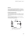
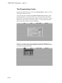
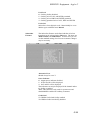
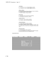
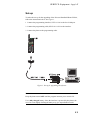
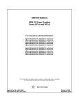
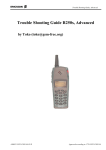
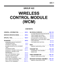
Figure 1. Service Equipment
6
SERVICE: Equipment
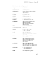
Other Equipment
Table 2
Equipment
Ordering Number
Personal Computer
(IBM PC/XT/AT Compatible)
Service Program
ETACS Products
Programming Interface
Connection Cable
Service Adapter
NTZ 112 180/4
KRY 105 045
KRY 101 1135/7
NTZ 112 178
Test Handset
Adapter Cable
Interconnector
Programming Cable
Antenna Cable
NTZ 112 211
NTZ 112 201/2
NTZ 112 241
KRY 101 1135/7
RPM 113 333/2
Torque Drive
Torque Bit
NTZ 112 287
NTZ 112 288
Note
1.3 m.
It is assumed that normal tools and soldering equipment are also available.
Note: When servicing mobile telephones, it is important to use a bench earthing network to protect sensitive components against electrostatic charges
(ESD).
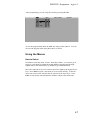
Service Program ETACS
The use of the service program is described in Appendix C, The Service Program ETACS.
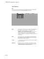
Test Handset
The built-in test program can be activated and run by a special control unit, the
Test Handset, or directly from the telephone. The Test Program Entry function must be enabled for accessing the test program directly from the telephone keypad.
Service Adapter
The Service Adapter is used in testing and repairing mobile telephones on the
service bench. It enables you to supply the mobile station with power and to
have certain functions displayed for control.
7
SERVICE: Equipment
8
Appendix A: Frequency Tables
Contents
Frequency Tables for the ETACS System ___________A-3
Table 1. Frequency Channels 1329 - 2047 ____________________A-4
Table 2. Frequency Channels 0 - 600 ________________________A-9
SERVICE: Equipment - App’x A
A-2
SERVICE: Equipment - App’x A
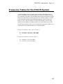
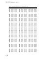
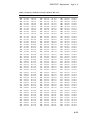
Frequency Tables for the ETACS System
A mobile telephone for the ETACS system operates in full duplex and provides 1320 channels with a channel spacing of 25 kHz (0.025 MHz) and a duplex separation of 45 MHz. The 900 MHz band has been divided into an upper
and a lower band. The lower sub-band, 872.0125 - 904.9875 MHz, covers the
1320 transmitting channels in the handheld telephone, while the upper subband, 917.0125 - 949.9875 MHz, covers the corresponding 1320 receiving
channels. The channels are numbered from 1329 to 2047 and from 0 to 600.
The following formulas can be used to calculate the frequencies (f, MHz) associated with a certain channel number (N = channel number).
Frequencies, channels 1329 - 2047 (see table 1):
fTx = 872.0125 + (N-1329) * 0.025 MHz
fRx = 917.0125 + (N-1329) * 0.025 MHz
Frequencies, channels 0 - 600 (see table 2):
fTx = 889.9875 + N * 0.025 MHz
fRx = 934.9875 + N * 0.025 MHz
A-3
SERVICE: Equipment - App’x A
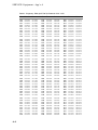
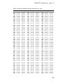
Table 1. Frequency Table for ETACS, Channels 1329 - 1478
A-4
Ch.
Tx
Rx
Ch.
Tx
Rx
Ch.
Tx
Rx
1329
1330
1331
1332
1333
1334
1335
1336
1337
1338
872.0125
872.0375
872.0625
872.0875
872.1125
872.1375
872.1625
872.1875
872.2125
872.2375
917.0125
917.0375
917.0625
917.0875
917.1125
917.1375
917.1625
917.1875
917.2125
917.2375
1379
1380
1381
1382
1383
1384
1385
1386
1387
1388
873.2625
873.2875
873.3125
873.3375
873.3625
873.3875
873.4125
873.4375
873.4625
873.4875
918.2625
918.2875
918.3125
918.3375
918.3625
918.3875
918.4125
918.4375
918.4625
918.4875
1429
1430
1431
1432
1433
1434
1435
1436
1437
1438
874.5125
874.5375
874.5625
874.5875
874.6125
874.6375
874.6625
874.6875
874.7125
874.7375
919.5125
919.5375
919.5625
919.5875
919.6125
919.6375
919.6625
919.6875
919.7125
919.7375
1339
1340
1341
1342
1343
1344
1345
1346
1347
1348
872.2625
872.2875
872.3125
872.3375
872.3625
872.3875
872.4125
872.4375
872.4625
872.4875
917.2625
917.2875
917.3125
917.3375
917.3625
917.3875
917.4125
917.4375
917.4625
917.4875
1389
1390
1391
1392
1393
1394
1395
1396
1397
1398
873.5125
873.5375
873.5625
873.5875
873.6125
873.6375
873.6625
873.6875
873.7125
873.7375
918.5125
918.5375
918.5625
918.5875
918.6125
918.6375
918.6625
918.6875
918.7125
918.7375
1439
1440
1441
1442
1443
1444
1445
1446
1447
1448
874.7625
874.7875
874.8125
874.8375
874.8625
874.8875
874.9125
874.9375
874.9625
874.9875
919.7625
919.7875
919.8125
919.8375
919.8625
919.8875
919.9125
919.9375
919.9625
919.987
1349
1350
1351
1352
1353
1354
1355
1356
1357
1358
872.5125
872.5375
872.5625
872.5875
872.6125
872.6375
872.6625
872.6875
872.7125
872.7375
917.5125
917.5375
917.5625
917.5875
917.6125
917.6375
917.6625
917.6875
917.7125
917.7375
1399
1400
1401
1402
1403
1404
1405
1406
1407
1408
873.7625
873.7875
873.8125
873.8375
873.8625
873.8875
873.9125
873.9375
873.9625
873.9875
918.7625
918.7875
918.8125
918.8375
918.8625
918.8875
918.9125
918.9375
918.9625
918.9875
1449
1450
1451
1452
1453
1454
1455
1456
1457
1458
875.0125
875.0375
875.0625
875.0875
875.1125
875.1375
875.1625
875.1875
875.2125
875.2375
920.0125
920.0375
920.0625
920.0875
920.1125
920.1375
920.1625
920.1875
920.2125
920.2375
1359
1360
1361
1362
1363
1364
1365
1366
1367
1368
872.7625
872.7875
872.8125
872.8375
872.8625
872.8875
872.9125
872.9375
872.9625
872.9875
917.7625
917.7875
917.8125
917.8375
917.8625
917.8875
917.9125
917.9375
917.9625
917.9875
1409
1410
1411
1412
1413
1414
1415
1416
1417
1418
874.0125
874.0375
874.0625
874.0875
874.1125
874.1375
874.1625
874.1875
874.2125
874.2375
919.0125
919.0375
919.0625
919.0875
919.1125
919.1375
919.1625
919.1875
919.2125
919.2375
1459
1460
1461
1462
1463
1464
1465
1466
1467
1468
875.2625
875.2875
875.3125
875.3375
875.3625
875.3875
875.4125
875.4375
875.4625
875.4875
920.2625
920.2875
920.3125
920.3375
920.3625
920.3875
920.4125
920.4375
920.4625
920.4875
1369
1370
1371
1372
1373
1374
1375
1376
1377
1378
873.0125
873.0375
873.0625
873.0875
873.1125
873.1375
873.1625
873.1875
873.2125
873.2375
918.0125
918.0375
918.0625
918.0875
918.1125
918.1375
918.1625
918.1875
918.2125
918.2375
1419
1420
1421
1422
1423
1424
1425
1426
1427
1428
874.2625
874.2875
874.3125
874.3375
874.3625
874.3875
874.4125
874.4375
874.4625
874.4875
919.2625
919.2875
919.3125
919.3375
919.3625
919.3875
919.4125
919.4375
919.4625
919.4875
1469
1470
1471
1472
1473
1474
1475
1476
1477
1478
875.5125
875.5375
875.5625
875.5875
875.6125
875.6375
875.6625
875.6875
875.7125
875.7375
920.5125
920.5375
920.5625
920.5875
920.6125
920.6375
920.6625
920.6875
920.7125
920.7375
SERVICE: Equipment - App’x A
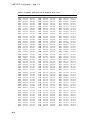
Table 1. Frequency Table for ETACS, Channels 1479 - 1628
Ch.
Tx
Rx
Ch.
Tx
Rx
Ch.
Tx
Rx
1479
1480
1481
1482
1483
1484
1485
1486
1487
1488
875.7625
875.7875
875.8125
875.8375
875.8625
875.8875
875.9125
875.9375
875.9625
875.9875
920.7625
920.7875
920.8125
920.8375
920.8625
920.8875
920.9125
920.9375
920.9625
920.9875
1529
1530
1531
1532
1533
1534
1535
1536
1537
1538
877.0125
877.0375
877.0625
877.0875
877.1125
877.1375
877.1625
877.1875
877.2125
877.2375
922.0125
922.0375
922.0625
922.0875
922.1125
922.1375
922.1625
922.1875
922.2125
922.2375
1579
1580
1581
1582
1583
1584
1585
1586
1587
1588
878.2625
878.2875
878.3125
878.3375
878.3625
878.3875
878.4125
878.4375
878.4625
878.4875
923.2625
923.2875
923.3125
923.3375
923.3625
923.3875
923.4125
923.4375
923.4625
923.4875
1489
1490
1491
1492
1493
1494
1495
1496
1497
1498
876.0125
876.0375
876.0625
876.0875
876.1125
876.1375
876.1625
876.1875
876.2125
876.2375
921.0125
921.0375
921.0625
921.0875
921.1125
921.1375
921.1625
921.1875
921.2125
921.2375
1539
1540
1541
1542
1543
1544
1545
1546
1547
1548
877.2625
877.2875
877.3125
877.3375
877.3625
877.3875
877.4125
877.4375
877.4625
877.4875
922.2625
922.2875
922.3125
922.3375
922.3625
922.3875
922.4125
922.4375
922.4625
922.4875
1589
1590
1591
1592
1593
1594
1595
1596
1597
1598
878.5125
878.5375
878.5625
878.5875
878.6125
878.6375
878.6625
878.6875
878.7125
878.7375
923.5125
923.5375
923.5625
923.5875
923.6125
923.6375
923.6625
923.6875
923.7125
923.7375
1499
1500
1501
1502
1503
1504
1505
1506
1507
1508
876.2625
876.2875
876.3125
876.3375
876.3625
876.3875
876.4125
876.4375
876.4625
876.4875
921.2625
921.2875
921.3125
921.3375
921.3625
921.3875
921.4125
921.4375
921.4625
921.4875
1549
1550
1551
1552
1553
1554
1555
1556
1557
1558
877.5125
877.5375
877.5625
877.5875
877.6125
877.6375
877.6625
877.6875
877.7125
877.7375
922.5125
922.5375
922.5625
922.5875
922.6125
922.6375
922.6625
922.6875
922.7125
922.7375
1599
1600
1601
1602
1603
1604
1605
1606
1607
1608
878.7625
878.7875
878.8125
878.8375
878.8625
878.8875
878.9125
878.9375
878.9625
878.9875
923.7625
923.7875
923.8125
923.8375
923.8625
923.8875
923.9125
923.9375
923.9625
923.9875
1509
1510
1511
1512
1513
1514
1515
1516
1517
1518
876.5125
876.5375
876.5625
876.5875
876.6125
876.6375
876.6625
876.6875
876.7125
876.7375
921.5125
921.5375
921.5625
921.5875
921.6125
921.6375
921.6625
921.6875
921.7125
921.7375
1559
1560
1561
1562
1563
1564
1565
1566
1567
1568
877.7625
877.7875
877.8125
877.8375
877.8625
877.8875
877.9125
877.9375
877.9625
877.9875
922.7625
922.7875
922.8125
922.8375
922.8625
922.8875
922.9125
922.9375
922.9625
922.9875
1609
1610
1611
1612
1613
1614
1615
1616
1617
1618
879.0125
879.0375
879.0625
879.0875
879.1125
879.1375
879.1625
879.1875
879.2125
879.2375
924.0125
924.0375
924.0625
924.0875
924.1125
924.1375
924.1625
924.1875
924.2125
924.2375
1519
1520
1521
1522
1523
1524
1525
1526
1527
1528
876.7625
876.7875
876.8125
876.8375
876.8625
876.8875
876.9125
876.9375
876.9625
876.9875
921.7625
921.7875
921.8125
921.8375
921.8625
921.8875
921.9125
921.9375
921.9625
921.9875
1569
1570
1571
1572
1573
1574
1575
1576
1577
1578
878.0125
878.0375
878.0625
878.0875
878.1125
878.1375
878.1625
878.1875
878.2125
878.2375
923.0125
923.0375
923.0625
923.0875
923.1125
923.1375
923.1625
923.1875
923.2125
923.2375
1619
1620
1621
1622
1623
1624
1625
1626
1627
1628
879.2625
879.2875
879.3125
879.3375
879.3625
879.3875
879.4125
879.4375
879.4625
879.4875
924.2625
924.2875
924.3125
924.3375
924.3625
924.3875
924.4125
924.4375
924.4625
924.4875
A-5
SERVICE: Equipment - App’x A
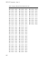
Table 1. Frequency Table for ETACS, Channels 1629 - 1778
A-6
Ch.
Tx
Rx
Ch.
Tx
Rx
Ch.
Tx
Rx
1629
1630
1631
1632
1633
1634
1635
1636
1637
1638
879.5125
879.5375
879.5625
879.5875
879.6125
879.6375
879.6625
879.6875
879.7125
879.7375
924.5125
924.5375
924.5625
924.5875
924.6125
924.6375
924.6625
924.6875
924.7125
924.7375
1679
1680
1681
1682
1683
1684
1685
1686
1687
1688
880.7625
880.7875
880.8125
880.8375
880.8625
880.8875
880.9125
880.9375
880.9625
880.9875
925.7625
925.7875
925.8125
925.8375
925.8625
925.8875
925.9125
925.9375
925.9625
925.9875
1729
1730
1731
1732
1733
1734
1735
1736
1737
1738
882.0125
882.0375
882.0625
882.0875
882.1125
882.1375
882.1625
882.1875
882.2125
882.2375
927.0125
927.0375
927.0625
927.0875
927.1125
927.1375
927.1625
927.1875
927.2125
927.2375
1639
1640
1641
1642
1643
1644
1645
1646
1647
1648
879.7625
879.7875
879.8125
879.8375
879.8625
879.8875
879.9125
879.9375
879.9625
879.9875
924.7625
924.7875
924.8125
924.8375
924.8625
924.8875
924.9125
924.9375
924.9625
924.9875
1689
1690
1691
1692
1693
1694
1695
1696
1697
1698
881.0125
881.0375
881.0625
881.0875
881.1125
881.1375
881.1625
881.1875
881.2125
881.2375
926.0125
926.0375
926.0625
926.0875
926.1125
926.1375
926.1625
926.1875
926.2125
926.2375
1739
1740
1741
1742
1743
1744
1745
1746
1747
1748
882.2625
882.2875
882.3125
882.3375
882.3625
882.3875
882.4125
882.4375
882.4625
882.4875
927.2625
927.2875
927.3125
927.3375
927.3625
927.3875
927.4125
927.4375
927.4625
927.4875
1649
1650
1651
1652
1653
1654
1655
1656
1657
1658
880.0125
880.0375
880.0625
880.0875
880.1125
880.1375
880.1625
880.1875
880.2125
880.2375
925.0125
925.0375
925.0625
925.0875
925.1125
925.1375
925.1625
925.1875
925.2125
925.2375
1699
1700
1701
1702
1703
1704
1705
1706
1707
1708
881.2625
881.2875
881.3125
881.3375
881.3625
881.3875
881.4125
881.4375
881.4625
881.4875
926.2625
926.2875
926.3125
926.3375
926.3625
926.3875
926.4125
926.4375
926.4625
926.4875
1749
1750
1751
1752
1753
1754
1755
1756
1757
1758
882.5125
882.5375
882.5625
882.5875
882.6125
882.6375
882.6625
882.6875
882.7125
882.7375
927.5125
927.5375
927.5625
927.5875
927.6125
927.6375
927.6625
927.6875
927.7125
927.7375
1659
1660
1661
1662
1663
1664
1665
1666
1667
1668
880.2625
880.2875
880.3125
880.3375
880.3625
880.3875
880.4125
880.4375
880.4625
880.4875
925.2625
925.2875
925.3125
925.3375
925.3625
925.3875
925.4125
925.4375
925.4625
925.4875
1709
1710
1711
1712
1713
1714
1715
1716
1717
1718
881.5125
881.5375
881.5625
881.5875
881.6125
881.6375
881.6625
881.6875
881.7125
881.7375
926.5125
926.5375
926.5625
926.5875
926.6125
926.6375
926.6625
926.6875
926.7125
926.7375
1759
1760
1761
1762
1763
1764
1765
1766
1767
1768
882.7625
882.7875
882.8125
882.8375
882.8625
882.8875
882.9125
882.9375
882.9625
882.9875
927.7625
927.7875
927.8125
927.8375
927.8625
927.8875
927.9125
927.9375
927.9625
927.9875
1669
1670
1671
1672
1673
1674
1675
1676
1677
1678
880.5125
880.5375
880.5625
880.5875
880.6125
880.6375
880.6625
880.6875
880.7125
880.7375
925.5125
925.5375
925.5625
925.5875
925.6125
925.6375
925.6625
925.6875
925.7125
925.7375
1719
1720
1721
1722
1723
1724
1725
1726
1727
1728
881.7625
881.7875
881.8125
881.8375
881.8625
881.8875
881.9125
881.9375
881.9625
881.9875
926.7625
926.7875
926.8125
926.8375
926.8625
926.8875
926.9125
926.9375
926.9625
926.9875
1769
1770
1771
1772
1773
1774
1775
1776
1777
1778
883.0125
883.0375
883.0625
883.0875
883.1125
883.1375
883.1625
883.1875
883.2125
883.2375
928.0125
928.0375
928.0625
928.0875
928.1125
928.1375
928.1625
928.1875
928.2125
928.2375
SERVICE: Equipment - App’x A
Table 1. Frequency Table for ETACS, Channels 1779 - 1928
Ch.
Tx
Rx
Ch.
Tx
Rx
Ch.
Tx
Rx
1779
1780
1781
1782
1783
1784
1785
1786
1787
1788
883.2625
883.2875
883.3125
883.3375
883.3625
883.3875
883.4125
883.4375
883.4625
883.4875
928.2625
928.2875
928.3125
928.3375
928.3625
928.3875
928.4125
928.4375
928.4625
928.4875
1829
1830
1831
1832
1833
1834
1835
1836
1837
1838
884.5125
884.5375
884.5625
884.5875
884.6125
884.6375
884.6625
884.6875
884.7125
884.7375
929.5125
929.5375
929.5625
929.5875
929.6125
929.6375
929.6625
929.6875
929.7125
929.7375
1879
1880
1881
1882
1883
1884
1885
1886
1887
1888
885.7625
885.7875
885.8125
885.8375
885.8625
885.8875
885.9125
885.9375
885.9625
885.9875
930.7625
930.7875
930.8125
930.8375
930.8625
930.8875
930.9125
930.9375
930.9625
930.9875
1789
1790
1791
1792
1793
1794
1795
1796
1797
1798
883.5125
883.5375
883.5625
883.5875
883.6125
883.6375
883.6625
883.6875
883.7125
883.7375
928.5125
928.5375
928.5625
928.5875
928.6125
928.6375
928.6625
928.6875
928.7125
928.7375
1839
1840
1841
1842
1843
1844
1845
1846
1847
1848
884.7625
884.7875
884.8125
884.8375
884.8625
884.8875
884.9125
884.9375
884.9625
884.9875
929.7625
929.7875
929.8125
929.8375
929.8625
929.8875
929.9125
929.9375
929.9625
929.9875
1889
1890
1891
1892
1893
1894
1895
1896
1897
1898
886.0125
886.0375
886.0625
886.0875
886.1125
886.1375
886.1625
886.1875
886.2125
886.2375
931.0125
931.0375
931.0625
931.0875
931.1125
931.1375
931.1625
931.1875
931.2125
931.2375
1799
1800
1801
1802
1803
1804
1805
1806
1807
1808
883.7625
883.7875
883.8125
883.8375
883.8625
883.8875
883.9125
883.9375
883.9625
883.9875
928.7625
928.7875
928.8125
928.8375
928.8625
928.8875
928.9125
928.9375
928.9625
928.9875
1849
1850
1851
1852
1853
1854
1855
1856
1857
1858
885.0125
885.0375
885.0625
885.0875
885.1125
885.1375
885.1625
885.1875
885.2125
885.2375
930.0125
930.0375
930.0625
930.0875
930.1125
930.1375
930.1625
930.1875
930.2125
930.2375
1899
1900
1901
1902
1903
1904
1905
1906
1907
1908
886.2625
886.2875
886.3125
886.3375
886.3625
886.3875
886.4125
886.4375
886.4625
886.4875
931.2625
931.2875
931.3125
931.3375
931.3625
931.3875
931.4125
931.4375
931.4625
931.4875
1809
1810
1811
1812
1813
1814
1815
1816
1817
1818
884.0125
884.0375
884.0625
884.0875
884.1125
884.1375
884.1625
884.1875
884.2125
884.2375
929.0125
929.0375
929.0625
929.0875
929.1125
929.1375
929.1625
929.1875
929.2125
929.2375
1859
1860
1861
1862
1863
1864
1865
1866
1867
1868
885.2625
885.2875
885.3125
885.3375
885.3625
885.3875
885.4125
885.4375
885.4625
885.4875
930.2625
930.2875
930.3125
930.3375
930.3625
930.3875
930.4125
930.4375
930.4625
930.4875
1909
1910
1911
1912
1913
1914
1915
1916
1917
1918
886.5125
886.5375
886.5625
886.5875
886.6125
886.6375
886.6625
886.6875
886.7125
886.7375
931.5125
931.5375
931.5625
931.5875
931.6125
931.6375
931.6625
931.6875
931.7125
931.7375
1819
1820
1821
1822
1823
1824
1825
1826
1827
1828
884.2625
884.2875
884.3125
884.3375
884.3625
884.3875
884.4125
884.4375
884.4625
884.4875
929.2625
929.2875
929.3125
929.3375
929.3625
929.3875
929.4125
929.4375
929.4625
929.4875
1869
1870
1871
1872
1873
1874
1875
1876
1877
1878
885.5125
885.5375
885.5625
885.5875
885.6125
885.6375
885.6625
885.6875
885.7125
885.7375
930.5125
930.5375
930.5625
930.5875
930.6125
930.6375
930.6625
930.6875
930.7125
930.7375
1919
1920
1921
1922
1923
1924
1925
1926
1927
1928
886.7625
886.7875
886.8125
886.8375
886.8625
886.8875
886.9125
886.9375
886.9625
886.9875
931.7625
931.7875
931.8125
931.8375
931.8625
931.8875
931.9125
931.9375
931.9625
931.9875
A-7
SERVICE: Equipment - App’x A
Table 1. Frequency Table for ETACS, Channels 1929 - 2047
A-8
Ch.
Tx
Rx
Ch.
Tx
Rx
Ch.
Tx
Rx
1929
1930
1931
1932
1933
1934
1935
1936
1937
1938
887.0125
887.0375
887.0625
887.0875
887.1125
887.1375
887.1625
887.1875
887.2125
887.2375
932.0125
932.0375
932.0625
932.0875
932.1125
932.1375
932.1625
932.1875
932.2125
932.2375
1979
1980
1981
1982
1983
1984
1985
1986
1987
1988
888.2625
888.2875
888.3125
888.3375
888.3625
888.3875
888.4125
888.4375
888.4625
888.4875
933.2625
933.2875
933.3125
933.3375
933.3625
933.3875
933.4125
933.4375
933.4625
933.4875
2029
2030
2031
2032
2033
2034
2035
2036
2037
2038
889.5125
889.5375
889.5625
889.5875
889.6125
889.6375
889.6625
889.6875
889.7125
889.7375
934.5125
934.5375
934.5625
934.5875
934.6125
934.6375
934.6625
934.6875
934.7125
934.7375
1939
1940
1941
1942
1943
1944
1945
1946
1947
1948
887.2625
887.2875
887.3125
887.3375
887.3625
887.3875
887.4125
887.4375
887.4625
887.4875
932.2625
932.2875
932.3125
932.3375
932.3625
932.3875
932.4125
932.4375
932.4625
932.4875
1989
1990
1991
1992
1993
1994
1995
1996
1997
1998
888.5125
888.5375
888.5625
888.5875
888.6125
888.6375
888.6625
888.6875
888.7125
888.7375
933.5125
933.5375
933.5625
933.5875
933.6125
933.6375
933.6625
933.6875
933.7125
933.7375
2039
2040
2041
2042
2043
2044
2045
2046
2047
889.7625
889.7875
889.8125
889.8375
889.8625
889.8875
889.9125
889.9375
889.9625
934.7625
934.7875
934.8125
934.8375
934.8625
934.8875
934.9125
934.9375
934.9625
1949
1950
1951
1952
1953
1954
1955
1956
1957
1958
887.5125
887.5375
887.5625
887.5875
887.6125
887.6375
887.6625
887.6875
887.7125
887.7375
932.5125
932.5375
932.5625
932.5875
932.6125
932.6375
932.6625
932.6875
932.7125
932.7375
1999
2000
2001
2002
2003
2004
2005
2006
2007
2008
888.7625
888.7875
888.8125
888.8375
888.8625
888.8875
888.9125
888.9375
888.9625
888.9875
933.7625
933.7875
933.8125
933.8375
933.8625
933.8875
933.9125
933.9375
933.9625
933.9875
1959
1960
1961
1962
1963
1964
1965
1966
1967
1968
887.7625
887.7875
887.8125
887.8375
887.8625
887.8875
887.9125
887.9375
887.9625
887.9875
932.7625
932.7875
932.8125
932.8375
932.8625
932.8875
932.9125
932.9375
932.9625
932.9875
2009
2010
2011
2012
2013
2014
2015
2016
2017
2018
889.0125
889.0375
889.0625
889.0875
889.1125
889.1375
889.1625
889.1875
889.2125
889.2375
934.0125
934.0375
934.0625
934.0875
934.1125
934.1375
934.1625
934.1875
934.2125
934.2375
1969
1970
1971
1972
1973
1974
1975
1976
1977
1978
888.0125
888.0375
888.0625
888.0875
888.1125
888.1375
888.1625
888.1875
888.2125
888.2375
933.0125
933.0375
933.0625
933.0875
933.1125
933.1375
933.1625
933.1875
933.2125
933.2375
2019
2020
2021
2022
2023
2024
2025
2026
2027
2028
889.2625
889.2875
889.3125
889.3375
889.3625
889.3875
889.4125
889.4375
889.4625
889.4875
934.2625
934.2875
934.3125
934.3375
934.3625
934.3875
934.4125
934.4375
934.4625
934.4875
SERVICE: Equipment - App’x A
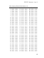
Table 2. Frequency Table for ETACS, Channels 0 - 149
Ch.
Tx
Rx
Ch.
Tx
Rx
Ch.
Tx
Rx
0
1
2
3
4
5
6
7
8
9
889.9875
890.0125
890.0375
890.0625
890.0875
890.1125
890.1375
890.1625
890.1875
890.2125
934.9875
935.0125
935.0375
935.0625
935.0875
935.1125
935.1375
935.1625
935.1875
935.2125
50
51
52
53
54
55
56
57
58
59
891.2375
891.2625
891.2875
891.3125
891.3375
891.3625
891.3875
891.4125
891.4375
891.4625
936.2375
936.2625
936.2875
936.3125
936.3375
936.3625
936.3875
936.4125
936.4375
936.4625
100
101
102
103
104
105
106
107
108
109
892.4875
892.5125
892.5375
892.5625
892.5875
892.6125
892.6375
892.6625
892.6875
892.7125
937.4875
937.5125
937.5375
937.5625
937.5875
937.6125
937.6375
937.6625
937.6875
937.7125
10
11
12
13
14
15
16
17
18
19
890.2375
890.2625
890.2875
890.3125
890.3375
890.3625
890.3875
890.4125
890.4375
890.4625
935.2375
935.2625
935.2875
935.3125
935.3375
935.3625
935.3875
935.4125
935.4375
935.4625
60
61
62
63
64
65
66
67
68
69
891.4875
891.5125
891.5375
891.5625
891.5875
891.6125
891.6375
891.6625
891.6875
891.7125
936.4875
936.5125
936.5375
936.5625
936.5875
936.6125
936.6375
936.6625
936.6875
936.7125
110
111
112
113
114
115
116
117
118
119
892.7375
892.7625
892.7875
892.8125
892.8375
892.8625
892.8875
892.9125
892.9375
892.9625
937.7375
937.7625
937.7875
937.8125
937.8375
937.8625
937.8875
937.9125
937.9375
937.9625
20
21
22
23
24
25
26
27
28
29
890.4875
890.5125
890.5375
890.5625
890.5875
890.6125
890.6375
890.6625
890.6875
890.7125
935.4875
935.5125
935.5375
935.5625
935.5875
935.6125
935.6375
935.6625
935.6875
935.7125
70
71
72
73
74
75
76
77
78
79
891.7375
891.7625
891.7875
891.8125
891.8375
891.8625
891.8875
891.9125
891.9375
891.9625
936.7375
936.7625
936.7875
936.8125
936.8375
936.8625
936.8875
936.9125
936.9375
936.9625
120
121
122
123
124
125
126
127
128
129
892.9875
893.0125
893.0375
893.0625
893.0875
893.1125
893.1375
893.1625
893.1875
893.2125
937.9875
938.0125
938.0375
938.0625
938.0875
938.1125
938.1375
938.1625
938.1875
938.2125
30
31
32
33
34
35
36
37
38
39
890.7375
890.7625
890.7875
890.8125
890.8375
890.8625
890.8875
890.9125
890.9375
890.9625
935.7375
935.7625
935.7875
935.8125
935.8375
935.8625
935.8875
935.9125
935.9375
935.9625
80
81
82
83
84
85
86
87
88
89
891.9875
892.0125
892.0375
892.0625
892.0875
892.1125
892.1375
892.1625
892.1875
892.2125
936.9875
937.0125
937.0375
937.0625
937.0875
937.1125
937.1375
937.1625
937.1875
937.2125
130
131
132
133
134
135
136
137
138
139
893.2375
893.2625
893.2875
893.3125
893.3375
893.3625
893.3875
893.4125
893.4375
893.4625
938.2375
938.2625
938.2875
938.3125
938.3375
938.3625
938.3875
938.4125
938.4375
938.4625
40
41
42
43
44
45
46
47
48
49
890.9875
891.0125
891.0375
891.0625
891.0875
891.1125
891.1375
891.1625
891.1875
891.2125
935.9875
936.0125
936.0375
936.0625
936.0875
936.1125
936.1375
936.1625
936.1875
936.2125
90
91
92
93
94
95
96
97
98
99
892.2375
892.2625
892.2875
892.3125
892.3375
892.3625
892.3875
892.4125
892.4375
892.4625
937.2375
937.2625
937.2875
937.3125
937.3375
937.3625
937.3875
937.4125
937.4375
937.4625
140
141
142
143
144
145
146
147
148
149
893.4875
893.5125
893.5375
893.5625
893.5875
893.6125
893.6375
893.6625
893.6875
893.7125
938.4875
938.5125
938.5375
938.5625
938.5875
938.6125
938.6375
938.6625
938.6875
938.7125
A-9
SERVICE: Equipment - App’x A
Table 2. Frequency Table for ETACS, Channels 150 - 299
Ch.
A-10
Tx
Rx
150
151
152
153
154
155
156
157
158
159
893.7375
893.7625
893.7875
893.8125
893.8375
893.8625
893.8875
893.9125
893.9375
893.9625
938.7375
938.7625
938.7875
938.8125
938.8375
938.8625
938.8875
938.9125
938.9375
938.9625
160
161
162
163
164
165
166
167
168
169
893.9875
894.0125
894.0375
894.0625
894.0875
894.1125
894.1375
894.1625
894.1875
894.2125
170
171
172
173
174
175
176
177
178
179
Ch.
Tx
Rx
200
201
202
203
204
205
206
207
208
209
894.9875
895.0125
895.0375
895.0625
895.0875
895.1125
895.1375
895.1625
895.1875
895.2125
939.9875
940.0125
940.0375
940.0625
940.0875
940.1125
940.1375
940.1625
940.1875
940.2125
938.9875
939.0125
939.0375
939.0625
939.0875
939.1125
939.1375
939.1625
939.1875
939.2125
210
211
212
213
214
215
216
217
218
219
895.2375
895.2625
895.2875
895.3125
895.3375
895.3625
895.3875
895.4125
895.4375
895.4625
894.2375
894.2625
894.2875
894.3125
894.3375
894.3625
894.3875
894.4125
894.4375
894.4625
939.2375
939.2625
939.2875
939.3125
939.3375
939.3625
939.3875
939.4125
939.4375
939.4625
220
221
222
223
224
225
226
227
228
229
180
181
182
183
184
185
186
187
188
189
894.4875
894.5125
894.5375
894.5625
894.5875
894.6125
894.6375
894.6625
894.6875
894.7125
939.4875
939.5125
939.5375
939.5625
939.5875
939.6125
939.6375
939.6625
939.6875
939.7125
190
191
192
193
194
195
196
197
198
199
894.7375
894.7625
894.7875
894.8125
894.8375
894.8625
894.8875
894.9125
894.9375
894.9625
939.7375
939.7625
939.7875
939.8125
939.8375
939.8625
939.8875
939.9125
939.9375
939.9625
Ch.
Tx
Rx
250
251
252
253
254
255
256
257
258
259
896.2375
896.2625
896.2875
896.3125
896.3375
896.3625
896.3875
896.4125
896.4375
896.4625
941.2375
941.2625
941.2875
941.3125
941.3375
941.3625
941.3875
941.4125
941.4375
941.4625
940.2375
940.2625
940.2875
940.3125
940.3375
940.3625
940.3875
940.4125
940.4375
940.4625
260
261
262
263
264
265
266
267
268
269
896.4875
896.5125
896.5375
896.5625
896.5875
896.6125
896.6375
896.6625
896.6875
896.7125
941.4875
941.5125
941.5375
941.5625
941.5875
941.6125
941.6375
941.6625
941.6875
941.7125
895.4875
895.5125
895.5375
895.5625
895.5875
895.6125
895.6375
895.6625
895.6875
895.7125
940.4875
940.5125
940.5375
940.5625
940.5875
940.6125
940.6375
940.6625
940.6875
940.7125
270
271
272
273
274
275
276
277
278
279
896.7375
896.7625
896.7875
896.8125
896.8375
896.8625
896.8875
896.9125
896.9375
896.9625
941.7375
941.7625
941.7875
941.8125
941.8375
941.8625
941.8875
941.9125
941.9375
941.9625
230
231
232
233
234
235
236
237
238
239
895.7375
895.7625
895.7875
895.8125
895.8375
895.8625
895.8875
895.9125
895.9375
895.9625
940.7375
940.7625
940.7875
940.8125
940.8375
940.8625
940.8875
940.9125
940.9375
940.9625
280
281
282
283
284
285
286
287
288
289
896.9875
897.0125
897.0375
897.0625
897.0875
897.1125
897.1375
897.1625
897.1875
897.2125
941.9875
942.0125
942.0375
942.0625
942.0875
942.1125
942.1375
942.1625
942.1875
942.2125
240
241
242
243
244
245
246
247
248
249
895.9875
896.0125
896.0375
896.0625
896.0875
896.1125
896.1375
896.1625
896.1875
896.2125
940.9875
941.0125
941.0375
941.0625
941.0875
941.1125
941.1375
941.1625
941.1875
941.2125
290
291
292
293
294
295
296
297
298
299
897.2375
897.2625
897.2875
897.3125
897.3375
897.3625
897.3875
897.4125
897.4375
897.4625
942.2375
942.2625
942.2875
942.3125
942.3375
942.3625
942.3875
942.4125
942.4375
942.4625
SERVICE: Equipment - App’x A
Table 2. Frequency Table for ETACS, Channels 300 - 449
Ch.
Tx
Rx
300
301
302
303
304
305
306
307
308
309
897.4875
897.5125
897.5375
897.5625
897.5875
897.6125
897.6375
897.6625
897.6875
897.7125
942.4875
942.5125
942.5375
942.5625
942.5875
942.6125
942.6375
942.6625
942.6875
942.7125
310
311
312
313
314
315
316
317
318
319
897.7375
897.7625
897.7875
897.8125
897.8375
897.8625
897.8875
897.9125
897.9375
897.9625
320
321
322
323
324
325
326
327
328
329
Ch.
Tx
Rx
350
351
352
353
354
355
356
357
358
359
898.7375
898.7625
898.7875
898.8125
898.8375
898.8625
898.8875
898.9125
898.9375
898.9625
943.7375
943.7625
943.7875
943.8125
943.8375
943.8625
943.8875
943.9125
943.9375
943.9625
942.7375
942.7625
942.7875
942.8125
942.8375
942.8625
942.8875
942.9125
942.9375
942.9625
360
361
362
363
364
365
366
367
368
369
898.9875
899.0125
899.0375
899.0625
899.0875
899.1125
899.1375
899.1625
899.1875
899.2125
897.9875
898.0125
898.0375
898.0625
898.0875
898.1125
898.1375
898.1625
898.1875
898.2125
942.9875
943.0125
943.0375
943.0625
943.0875
943.1125
943.1375
943.1625
943.1875
943.2125
370
371
372
373
374
375
376
377
378
379
330
331
332
333
334
335
336
337
338
339
898.2375
898.2625
898.2875
898.3125
898.3375
898.3625
898.3875
898.4125
898.4375
898.4625
943.2375
943.2625
943.2875
943.3125
943.3375
943.3625
943.3875
943.4125
943.4375
943.4625
340
341
342
343
344
345
346
347
348
349
898.4875
898.5125
898.5375
898.5625
898.5875
898.6125
898.6375
898.6625
898.6875
898.7125
943.4875
943.5125
943.5375
943.5625
943.5875
943.6125
943.6375
943.6625
943.6875
943.7125
Ch.
Tx
Rx
400
401
402
403
404
405
406
407
408
409
899.9875
900.0125
900.0375
900.0625
900.0875
900.1125
900.1375
900.1625
900.1875
900.2125
944.9875
945.0125
945.0375
945.0625
945.0875
945.1125
945.1375
945.1625
945.1875
945.2125
943.9875
944.0125
944.0375
944.0625
944.0875
944.1125
944.1375
944.1625
944.1875
944.2125
410
411
412
413
414
415
416
417
418
419
900.2375
900.2625
900.2875
900.3125
900.3375
900.3625
900.3875
900.4125
900.4375
900.4625
945.2375
945.2625
945.2875
945.3125
945.3375
945.3625
945.3875
945.4125
945.4375
945.4625
899.2375
899.2625
899.2875
899.3125
899.3375
899.3625
899.3875
899.4125
899.4375
899.4625
944.2375
944.2625
944.2875
944.3125
944.3375
944.3625
944.3875
944.4125
944.4375
944.4625
420
421
422
423
424
425
426
427
428
429
900.4875
900.5125
900.5375
900.5625
900.5875
900.6125
900.6375
900.6625
900.6875
900.7125
945.4875
945.5125
945.5375
945.5625
945.5875
945.6125
945.6375
945.6625
945.6875
945.7125
380
381
382
383
384
385
386
387
388
389
899.4875
899.5125
899.5375
899.5625
899.5875
899.6125
899.6375
899.6625
899.6875
899.7125
944.4875
944.5125
944.5375
944.5625
944.5875
944.6125
944.6375
944.6625
944.6875
944.7125
430
431
432
433
434
435
436
437
438
439
900.7375
900.7625
900.7875
900.8125
900.8375
900.8625
900.8875
900.9125
900.9375
900.9625
945.7375
945.7625
945.7875
945.8125
945.8375
945.8625
945.8875
945.9125
945.9375
945.9625
390
391
392
393
394
395
396
397
398
399
899.7375
899.7625
899.7875
899.8125
899.8375
899.8625
899.8875
899.9125
899.9375
899.9625
944.7375
944.7625
944.7875
944.8125
944.8375
944.8625
944.8875
944.9125
944.9375
944.9625
440
441
442
443
444
445
446
447
448
449
900.9875
901.0125
901.0375
901.0625
901.0875
901.1125
901.1375
901.1625
901.1875
901.2125
945.9875
946.0125
946.0375
946.0625
946.0875
946.1125
946.1375
946.1625
946.1875
946.2125
A-11
SERVICE: Equipment - App’x A
Table 2. Frequency Table for ETACS, Channels 450 - 600
Ch.
A-12
Tx
Rx
450
451
452
453
454
455
456
457
458
459
901.2375
901.2625
901.2875
901.3125
901.3375
901.3625
901.3875
901.4125
901.4375
901.4625
946.2375
946.2625
946.2875
946.3125
946.3375
946.3625
946.3875
946.4125
946.4375
946.4625
460
461
462
463
464
465
466
467
468
469
901.4875
901.5125
901.5375
901.5625
901.5875
901.6125
901.6375
901.6625
901.6875
901.7125
470
471
472
473
474
475
476
477
478
479
Ch.
Tx
Rx
500
501
502
503
504
505
506
507
508
509
902.4875
902.5125
902.5375
902.5625
902.5875
902.6125
902.6375
902.6625
902.6875
902.7125
947.4875
947.5125
947.5375
947.5625
947.5875
947.6125
947.6375
947.6625
947.6875
947.7125
946.4875
946.5125
946.5375
946.5625
946.5875
946.6125
946.6375
946.6625
946.6875
946.7125
510
511
512
513
514
515
516
517
518
519
902.7375
902.7625
902.7875
902.8125
902.8375
902.8625
902.8875
902.9125
902.9375
902.9625
901.7375
901.7625
901.7875
901.8125
901.8375
901.8625
901.8875
901.9125
901.9375
901.9625
946.7375
946.7625
946.7875
946.8125
946.8375
946.8625
946.8875
946.9125
946.9375
946.9625
520
521
522
523
524
525
526
527
528
529
480
481
482
483
484
485
486
487
488
489
901.9875
902.0125
902.0375
902.0625
902.0875
902.1125
902.1375
902.1625
902.1875
902.2125
946.9875
947.0125
947.0375
947.0625
947.0875
947.1125
947.1375
947.1625
947.1875
947.2125
490
491
492
493
494
495
496
497
498
499
902.2375
902.2625
902.2875
902.3125
902.3375
902.3625
902.3875
902.4125
902.4375
902.4625
947.2375
947.2625
947.2875
947.3125
947.3375
947.3625
947.3875
947.4125
947.4375
947.4625
Ch.
Tx
Rx
550
551
552
553
554
555
556
557
558
559
903.7375
903.7625
903.7875
903.8125
903.8375
903.8625
903.8875
903.9125
903.9375
903.9625
948.7375
948.7625
948.7875
948.8125
948.8375
948.8625
948.8875
948.9125
948.9375
948.9625
947.7375
947.7625
947.7875
947.8125
947.8375
947.8625
947.8875
947.9125
947.9375
947.9625
560
561
562
563
564
565
566
567
568
569
903.9875
904.0125
904.0375
904.0625
904.0875
904.1125
904.1375
904.1625
904.1875
904.2125
948.9875
949.0125
949.0375
949.0625
949.0875
949.1125
949.1375
949.1625
949.1875
949.2125
902.9875
903.0125
903.0375
903.0625
903.0875
903.1125
903.1375
903.1625
903.1875
903.2125
947.9875
948.0125
948.0375
948.0625
948.0875
948.1125
948.1375
948.1625
948.1875
948.2125
570
571
572
573
574
575
576
577
578
579
904.2375
904.2625
904.2875
904.3125
904.3375
904.3625
904.3875
904.4125
904.4375
904.4625
949.2375
949.2625
949.2875
949.3125
949.3375
949.3625
949.3875
949.4125
949.4375
949.4625
530
531
532
533
534
535
536
537
538
539
903.2375
903.2625
903.2875
903.3125
903.3375
903.3625
903.3875
903.4125
903.4375
903.4625
948.2375
948.2625
948.2875
948.3125
948.3375
948.3625
948.3875
948.4125
948.4375
948.4625
580
581
582
583
584
585
586
587
588
589
904.4875
904.5125
904.5375
904.5625
904.5875
904.6125
904.6375
904.6625
904.6875
904.7125
949.4875
949.5125
949.5375
949.5625
949.5875
949.6125
949.6375
949.6625
949.6875
949.7125
540
541
542
543
544
545
546
547
548
549
903.4875
903.5125
903.5375
903.5625
903.5875
903.6125
903.6375
903.6625
903.6875
903.7125
948.4875
948.5125
948.5375
948.5625
948.5875
948.6125
948.6375
948.6625
948.6875
948.7125
590
591
592
593
594
595
596
597
598
599
600
904.7375
904.7625
904.7875
904.8125
904.8375
904.8625
904.8875
904.9125
904.9375
904.9625
904.9875
949.7375
949.7625
949.7875
949.8125
949.8375
949.8625
949.8875
949.9125
949.9375
949.9625
949.9875
Appendix B: Test Program
Contents
How to Use _________________________________________ B-3
Preparation ____________________________________________ B-3
Initiating the Test Program _______________________________ B-3
Display Test ___________________________________________ B-3
Selecting a Specific Test__________________________________ B-4
Return to TEST INPUT __________________________________ B-4
Exit __________________________________________________ B-4
Individual Test Options _____________________________ B-5
Table 1. Overview of the Test Program ____________________ B-16
Additional Tests _______________________________________ B-19
SERVICE: Equipment - App’x B
B-2
SERVICE: Equipment - App’x B
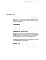
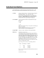
How to Use
This document will describe the use of the built-in test program for the handheld telephone. After the more extensive descriptions in Individual Test Options follows an overview in the form of a table with data pertaining to the
different options. With some experience with the test program you may find
this table a handy alternative.
Preparation
To prevent the telephone from switching off after 30 seconds in transmission
mode, the autonomous timeout function must be disabled. This can be done
by applying a voltage of +5 V at the VPPFLASH input (pin 9) of the external
connector J105, or by activating the Service switch on the Service Adapter.
Initiating the Test Program
The test program is activated from the special test handset by holding down
the M button and pressing R three times. However, if the Test Program Enter
function is enabled in the telephone, the program can be activated and run directly from the keypad by holding down the M button and pressing
904059
When the handheld telephone enters the test mode, the hardware is initialized.
The text TEST INPUT appears on the display.
Display Test
The test program can be activated and run by a test handset. The display is
tested with the aid of a special test option (No. 45).
B-3
SERVICE: Equipment - App’x B
Selecting a Specific Test
When the test program has been initiated, the prompt TEST INPUT appears
on the display. A test option is selected by entering X# or XY# (X and Y are
digits from 0 to 9).
You may also step up or down to the next option in the test program, using a
test handset; the SEND button for up-step and the RCL button for down-step.
The specified test option will then be performed, and a message shown on the
display. Any parameter set or read will be shown as well.
Data will be read and displayed once a second.
Selectable parameters may be altered by specifying the new value . If the new
value is approved, the setting will be altered as shown by the display, and the
current menu will remain active. If the new value is not approved, the old
value will remain.
Example
How the different parameters are selected and introduced into a test is explained in Individual Test Options. A complete series of entries may have the
structure shown below:
1 # 3 2 6 # C 2 # 2 C 23 # 3 C
The first figure (1) is the number of the option CHANNEL NUMBER selected in the test menu. The next (326) is a channel number indexed while
CHANNEL NUMBER applies.
The 2 after the asterisk indicates that option 2 TX POWER of the menu has
been selected. Here alternative 2 was chosen, which provides a transmission
power of 0.45 W, as you will find in the description of this particular option.
Lastly, option 23 in the menu, MANCHOUT, has been selected, and here alternative 3 will provide transmission of a special frame.
Return to TEST INPUT
Depress the C-button to return to the input mode, where the TEST INPUT
prompt is displayed.
Exit
To leave the test program, select test option 99.
B-4
SERVICE: Equipment - App’x B
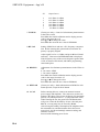
Individual Test Options
A list describing the use of the test program options follows below. A summary of the test options and possible parameter values is given in Table 1.
1 CH NR
Setting of channel number. The initial setting is channel 1.
Permissible settings: 1329 - 2047 and 0 - 600.
Select channel, indexing its number on the keypad and
pressing #. The ▲ and ▼ buttons can be used to step forwards or backwards from the current channel number.
Channel number and signal strength are displayed.
2 TX POWER
Sets the transmitter ON/OFF and determines the output
power level..
8 : OFF
7 : min
.
.
2 : max.
Note: The transmitter will go on only if the Tx and Rx synthesizers are locked.
The Power Reduction function (test 76), if activated,
causes 2 (Power Level 2) to be displayed as #.
3 LOCKTIME
(Factory use only). Measures Tx/Rx synth. locktime.
5 PWR CAL
Calibration of power levels.
The frequency band is divided into three parts with three
corresponding Transmitter Input Voltage Tables. Press 0, 1
or 2 to select either table.The table showing power level
and current voltage value is displayed, the initial value read
from the EEPROM. Use the ▲ and ▼ buttons to change
the value. Press M and S simultaneously to store the value
in EEPROM or M and # to step to the next power level.
When selecting a new table, the relevant channel for transmission is automatically selected.
Input Voltage Table and the corresponding channels:
Table
0
1
2
Used Channel Channels
1500
350
500
1329-200
201-450
451-600
Power Levels and Output Power that should exist on the respective level:
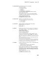
Continued on next page
B-5
SERVICE: Equipment - App’x B
PL
Output Power
2
3
4
5
6
7
26.5 dBm+2/-4 dBm
22.5 dBm+2/-4 dBm
18.5 dBm+2/-4 dBm
14.5 dBm+2/-4 dBm
10.5 dBm+2/-4 dBm
6.5 dBm+2/-4 dBm
7 TXSENS
(Factory use only). Control of soft trimmer potentiometers
in the LINA circuit.
Press M & # to enable calibration and to display present
value in the range 00 to 1F.
Press ▲ or ▼ to change the value.
Press M & S to store the new value in EEPROM.
9 RF CAL
Setting of RSSI level and max. AFC frequency compensation. Before entering this option make sure that the frequency is properly aligned.
Adjust signal level to -115 dBm, and press M and S simultaneously. Value stored in EEPROM/RAM is displayed.
If the frequency error of the received signal is greater than
1 kHz, an alarm will be heard, and further programming
cannot take place.
B-6
10 RXSENS
Adjustment of soft trimmer potentiometers in the LINA circuit.
0 : Rx source AFMS
1 : Rx source earphone
Press M & # to enable calibration and to display present
value in the range from 00 to 1F.
Press ▲ or ▼ to change the value.
Press M & S to store the new value in EEPROM.
11 KEYPAD
(Factory use only). Sends information on DFMS for each
button pressed, except for the C-button.
12 C CAL
Before entering this test, connect an ammeter between
power supply and telephone. The value to be used in calibration is the shown value in mA divided by 700 and multiplied by 30 (which provides a 1- or 2-digit decimal value).
When entering the test, the green LED and illumination
will go On. Enter the divided-by-25 mA value and press
M & S; a wrong entry may be erased by M & #.
After storing the standby consumption, the telephone turns
the transmitter On, and the ammeter shows the lowest
power level; divide and multiply ammeter reading, and
calibrate as before.
Proceed with remaining power levels.
SERVICE: Equipment - App’x B
13 BANDGAP
Calibration of Battery Full Level value and internal reference voltage ("Bandgap") in the BERTRAM circuit.
This calibration must be performed before any other calibration involving BERTRAM.
1. Adjust supply voltage to 5.3 V at battery connector and
press M & S to memorize this calibration. The two values
will be displayed - the Low Battery value in the AND*)
and the internal reference voltage in the DDD*).
2. Increase the voltage to 8.1 V and press M & S to memorise this calibration. The stored value will be shown in
the AND.
The program then returns to TEST INPUT.
*)
AND = Alpha/Numeric Display
DDD = Dialled Digits Display.
14 AUDDEV
Adjustment of soft trimmer potentiometers in the LINA circuit. Max. deviation.
This calibration must be performed before any other
calibration involving deviation.
Press M & # to enable calibration and to display present
value in the range from 00 to 0F.
Press ▲ or ▼ to change the value.
Press M & S to store the new value in EEPROM.
15 AFC
Selection of AFC mode (shown on the numeric display):
0 : AFC off
1 : Normal operation (default)
2 : Normal operation without age offset update
Any other code entered in Handset Mode will display:
TO TE FR S , where
TO = total compensation (temp.+ age + freq. error)
TE = temperature table compensation
FR = frequency error compensation
S = AFC state
1,2 = no valid RSSI
3 = locked to a channel;
4,5 = RSSI temperature lost
16 DAC1CAL
(Factory use only). Automatic trimming of the TxVCO
control input DC level (for radios with combined ceramic
duplex filter). Pressing M & 0 will activate calibration and
stored value will be shown on the DDD.
17 MF COUNT Counts how many E-clock cycles have elapsed while a
counter in CARL counted 2432 cycles of the 54 kHz signal
from BERTRAM. The number is subtracted from the correct number of cycles, and the result is shown as a 4-digit
hexadecimal number, the relevant plus or minus sign included.
B-7
SERVICE: Equipment - App’x B
B-8
18 DAC2CAL
Coarse calibration of the DAC for TCXO.
Check that the telephone is correctly tuned to a channel
and that the RF signal is strong.
Press M & 0, and calibration is performed automatically.
The stored value is displayed.
Alternatively:
Press M & # to enable calibration and to display present
value.
Press ▲ or ▼ to change the value.
Press M & S to store the new value in EEPROM.
Note: The AFC operation mode (test no.15) must be set to
normal operation.
19 RX SAT
Reads and displays the frequency of the received supervisory audio tone (SAT).
Possible readings: 5970, 6000, and 6030.
The routine samples the SAT twenty times and will show
the most sampled SAT together with the number of valid
samples.
20 AUDIO
Sets the audio paths in LINA.
0 : Both audio paths (ATMS & AFMS) disconnected
1 : Path out to handset (AFMS) disconnected;
into station (ATMS) connected
2 : Path out to handset (AFMS) connected;
into station (ATMS) disconnected
3 : Both audio paths (ATMS & AFMS) connected
(default condition).
21 HANDSET
Sets the audio paths in the handset.
0 : Microphone and earphone OFF,
speaker OFF (default condition)
1 : Microphone and earphone ON, speaker OFF
2 : Microphone and earphone OFF, speaker ON
22 TX SAT
Controls the SAT tone switch in LINA.
0 : 5970 Hz
1 : 6000 Hz
2 : 6030 Hz
3 : No SAT
4 : ON
5 : OFF
When the switch is on, it is also possible to adjust the soft
trimmer potentiometers in the LINA circuit:
Press M & # to enable calibration and to display present
value in the range from 00 to 0F.
Press ▲ or ▼ to change the value.
Press M & S to store the new value.
Note: Parameter no. 4 must be set (ON) before choosing
options 0-2 for adjustment.
Default conditions are 3: NoSAT and 5:OFF.
SERVICE: Equipment - App’x B
23 MANCHOUT Sets the data frames to be transmitted.
Permissible settings:
0 : OFF (Initial setting)
1 : All digital 1
2 : All digital 0
3 : A special frame is transmitted.
It is also possible to adjust the soft trimmer potentiometers in the LINA circuit.
The transmitter must be on (test #2) to transmit FFSK.
Press M & # to enable calibration and to display present
value in the range from 00 to 0F.
Press ▲ or ▼ to change the value.
Press M & S to store the new value.
24 MANCH IN
Displays received data when # is pressed.
The current channel type is shown as well:
1 : Control Channel
2 : Voice Channel
25 VOLUME
Sets the sound level of the speaker and earphone.
Possible values: 0-1-2-3-4-5-6-7
Lowest value: 0
Default value: 3
26 DTMF
DTMF tones consist of a lower frequency in combination
with a higher frequency. The test enables you to listen to
either or both as follows:
Press 0 for the low frequency
Press 1 for the high frequency
Press 2 for both frequencies.
The tones are then generated when ▲ and ▼ is pressed.
With each new depression of ▲ and ▼ comes a different
tone. The display (num. field) shows to which key the tone
refers.
Keys with DTMF tones: 0 -9, *, #. Tone generation is disabled when leaving the test option.
It is also possible to adjust the soft trimmer potentiometers
in the LINA circuit. Press M & # to enable calibration and
to display present value in the range from 00 to 1F.
27 TXSRC
Control of TX Source switch in LINA. Nominal deviation.
0 : External TX source;
ATMS through-connected to LINA (default)
1 : Internal TX source (MIC SIGNAL).
The test option also enables you to adjust the soft trimmer
potentiometers in the LINA circuit. 0 prepares for adjustment of the External, 1 for the Internal Mic Potentiometer:
Press M & # to enable calibration and display value in the
range from 00 to 1F.
Press ▲ or ▼ to change the value.
Press M & S to store the new value.
B-9
SERVICE: Equipment - App’x B
28 EARPIECE
Controls the Earpiece Mute switch in the LINA circuit.
0 : Internal earpiece disconnected (default)
1 : Internal earpiece connected.
With earpiece connected the test option also permits adjustment of the soft trimming potentiometer in the LINA circuit:
Press M & # to enable calibration and display present
value in the range from 00 to 0F.
Press ▲ or ▼to change the value.
Press M & S to store the new value.
29 COMP
Selects companding or linear mode, where linear mode is
the default condition.
Press M & # for display of actual mode, indicated as follows:
00 : Linear mode / bypass compander
01 : LINA compander, external audio
02 : LINA compander
03 : External compander, companding mode.
To change the mode, press M and the respective digit per
the above table (omitting the 0).
30 HF
Controls the internal HF in the LINA circuit
M & 0 = HF Rx path
M & 1 = HF Tx path
Gain
dB
0
1
2
3
4
5
6
7
0
-7
-14
-21
-28
-35
-42
-49
If a path, Rx or Tx, is chosen, a corresponding ADC value
is displayed continuously on the AND.
By pressing M & S it is also possible to calibrate Rx and
Tx parameters used by the internal HF. Once calibration
has been performed the stored values will be displayed;
Tx on AND and Rx on DDD.
Note: LINA and BERTRAM must have been in operation for at least 10 sec before calibration is started.
33 ACCUMLTD Reset of Accumulated Air Timer. Press M & # to reset.
# is shown after completed operation.
B-10
SERVICE: Equipment - App’x B
34 BAUD
This option controls the Baud Rate clock in the CARL circuit as follows:
0 : 600 baud
1 : 1200 baud
2 : 2400 baud
3 : 4800 baud
4 : 9600 baud
36 HI Z
(Factory use only). Sets the HI_Z_AFMS port on the
LINA circuit.
0 : Output Low (default)
1 : Output High.
38 ADC
Displays (alpha-num. field) once a second the value of the
Analog/Digital Converters. Select ADC by pressing M
and the respective digit shown below:
1 : RSSI
2 : BATT
3 : TX VCO
4 : TEMPSENSE (inside mobile)
5 : BTEMP (battery temp.)
6 : HFSENSE.
39 DAC
Changes temporarily the output voltage from the Digital/Analog Converters. Select DAC by pressing M and the
respective digit as follows:
1 : DAC for adjustment of the DC level for the Tx VCO
2 : DAC for course adjustment of the VCTCXO
3 : DAC controlling the transmission power level.
Change voltage by pressing ▲ and ▼, or by entering a
decimal value followed by M & #.
The initial values will be resumed when leaving the test option.
40 INPORT
Shows, once a second, the status on the inports selected by
pressing M and the corresponding figure, see below.
1 : PWRSRC (on CARL)
0 : Input High (battery)
1 : Input Low (externally powered).
2 : RX LOCK (on BERTRAM)
0 : Input Low
1 : Input High (locked).
3 : TX LOCK (on BERTRAM)
0 : Input Low
1 : Input High (locked).
4 : POWDET
0 : Transmitter Off
1 : Transmitter On
5 : ICAP (on CARL)
0 : Input Low
1 : Input High.
Continued on next page
B-11
SERVICE: Equipment - App’x B
6 : HF REQ (HOOK) (on CPU)
0 : Input Low
1 : Input High.
7 : RXCD (on CARL); RSSI compared to sensitivity limit
0 : RSSI 0dB limit
1 : RSSI 0dB limit
B-12
41 OUTPORT
Shows the status on the outports selected by pressing M
and the corresponding figure, see below.
1 : ICTRL (on CPU)
0 : Output Low
1 : Output High
2 : LSPCTRL (on CPU)
0 : Output Low
1 : Output High
3 : TXON1 (on BERTRAM)
0 : Active
1 : Not active
4 : SWVREG (on BERTRAM)
0 : SWREG On
1 : SWREG Off
5 : VPAON (on BERTRAM)
0 : Not active
1 : Active
6 : VTX (on BERTRAM)
0 : Active
1 : Not active
7 : VRADON (on BERTRAM)
0 : Active
1 : Not active
8 : LED1 (green LED porton CARL)
0 : Not active
1 : Active
9 : LED2 (red LED port on CARL)
0 : Not active
1 : Active
10: ILLUM (on CARL), selected by pressing 0 only,
0 : Not active
1 : Active
42 DSCR MLT
Turns on and off the discriminator and the multiplier in the
BERTRAM circuit.
0 : OFF
1 : ON
43 BAR
Ringing:
Press 0 to activate
Alarm Signal: Press 1 to activate
Click Signal: Press 2 to activate
Error Signal: Press 3 to activate.
SERVICE: Equipment - App’x B
44 LCD
45 DSP TEST
Controls the LCD contrast via VLCD1 output on the
CARL circuit. Entered values, in the range from 00 to FF,
as described below:
To enter
Press
0...9
A
B
C
D
E
F
0...9
M&0
M&1
M&2
M&3
M&4
M&5
Pressing # causes all display segments to flash. The test is
carried out in five steps with different patterns, each pattern shown for 2 seconds. Will continue until C is
pressed.
46 PWR DOWN The default value "1" provides normal operating
mode. Pressing the 0 key sets BERTRAM and LINA in
power down mode, and removes power from the compander.
47 PROG NAM Displays the product number and revision status of the
EPROM program, when # is pressed.
50 GUARANT
Displays the guarantee start (year and month), and its duration (months) when # is pressed.
54 STARTUP
(Factory use only). In this test different parts of the memory can be initiated with default data resident in the program.
M & S initiates all Data Areas except the radio parameter
area:
- Short Numbers
- Customer Data
- ESN (dummy)
- PIN code
- Current Backup Area
M & # initiates the radio parameters (including calibrated
values), LINA trimpots, and some of the other trimpots,
e.g. Coarse TCXO DAC.
M & * initiates the Customer Data Area.
M & 2 initiates default PIN code.
M & 1 initiates the the ESN positions with a dummy number. This option may be used when the ESN positions do
not contain a proper ESN number, which causes the telephone to switch off itself.
M & 0 destroys an EE pattern, which will cause Backup
Area No. 0, the very first one, to be initiated at the next
Power On. Backup area counting will start at 0.
B-13
SERVICE: Equipment - App’x B
B-14
55 WAVE
(Factory use only). Selection of square wave or triangle
wave generation in BERTRAM. 00 on the display indicates square wave, 01 triangle wave.
Press M & # to display actual value. Change by pressing
M and the alternative figure, 0 or 1. Press M & S to store
the new value.
56 OSCA
(Factory use only). Change of oscillator amplification
from BERTRAM.
Press M & # to enable calibration and to display present
value.
Press ▲ or ▼ to change the value.
Press M & S to store the new value.
Note: Although all values up to 1F are allowed, only the
following ones are significant:
1F : 1 1111 (highest amplification)
1E : 1 1110
1C : 1 1100
18 : 1 1000
10 : 1 0000
00 : 0 0000 (lowest amplification)
57 OSCD
(Factory use only). Change of oscillator duty cycle from
BERTRAM.
Check that the telephone is tuned correctly to a channel
and that the HF signal is strong.
Press M & 0, and calibration will be performed automatically. The stored value will be displayed on the alphanumeric display.
Alternatively, press M & # to enable calibration and to display present value in the range from 00 to 7F.
Press ▲ or ▼ to change the value.
Press M & S to store the new value.
59 LO RXTX
(Factory use only). Change of synth. threshold in BERTRAM.
Press M & # to enable calibration and to display present
value in the range from 00 to 7F.
Press ▲ or ▼ to change the value.
Press M & S to store the new value.
60 CINDY
(Factory use only). With this option it is possible to control the circuit by special codes. Cannot be used in Handset mode.
61 LINA
(Factory use only). With this option it is possible to control the circuit by special codes. Cannot be used in Handset mode.
62 BERTRAM
(Factory use only). With this option it is possible to control the circuit by special codes. Cannot be used in Handset mode.
SERVICE: Equipment - App’x B
74 TCATEST
Special software test of combining algorithm according to
TACS specifications. Press # to display:
01 : OK
00 : Fail
76 BATTSAVE Controls the Reduced Power function. Enter 0/1 to deactivate/activate. Deactivated is default condition. (valid for
PL2 only)
77 EE DATA
Factory use only
B-15
SERVICE: Equipment - App’x B
Table 1. Overview of the Test Program
(default values in italics)
Option
B-16
Possible Values
1 Channel Number
1329-2047, 0-600, (1)
2 Transmission Power
8 : 0 W, 7: min., 2: max.
5 Power Calibration
Programs the Power Level positions
in EEPROM
9 RF Calibration
Setting of RSSI level and max. frequency
compensation in the EEPROM
10 RXSENS
Sets Audio Gain trimmer in LINA.
Change value by ▲ or ▼
12 Current Calibration
Ammeter value divided by 700 and
multiplied by 30
13 Battery Calibration
Memorize supply at 5.3 V, increase to
8.1 V and memorize again (M&S)
14 Audio Deviation
Change value by ▲ or ▼
15 AFC
0 : AFC OFF
1 : Normal mode
17 MF Count
Hex. value
18 VCO Calibration
Press M&0 for aut. cal.
19 RX SAT
Displays frequency of received SAT
20 Audio
0 : Paths to and from handset (hs) closed
1 : Path to hs closed; from hs open
2 : = 1: reversed
3 : both paths open
21 Handset
0 :Mic. & earphone OFF, speaker OFF
1 :Mic. & earphone ON, speaker OFF
2 :Mic. & earphone OFF, speaker ON
22 TX SAT
0 : 5970 Hz
1 : 6000 Hz
2 : 6030 Hz
3 : no SAT
4 : SAT switch in LINA ON
5 : SAT switch in LINA OFF
SERVICE: Equipment - App’x B
Table 1. Overview of the Test Program, cont’d
Option
Possible Values
23 Manchester Out
Sets Tx data patterns
24 Manchester In
Displays channel type and received data
when # is pressed
25 Volume
0-7, 3 default, 7 max.
26 DTMF
DTMF tones on 0-9, *, #
27 TX Source
0 : External, 1: internal
28 Earpiece
0 : Internal earpiece Off, 1: On
29 Compander
M&3: ext. comp. (companding mode)
M&2: LINA compander
M&1: LINA comp. external radio
M&0: Linear mode
30 HF
Controls internal HF in LINA.
33 Accumulated Air Time
M&# to reset
34 BAUD
0 : 600; 1 : 1200, 2 : 2400;
3 : 4800; 4 : 9600 baud
38 ADC
M&1: RSSI, M&2: Batt,
M&3: reflected Tx pwr, M&4: Tempsense,
M&5: Btemp.
39 DAC
M&1: DAC1, M&2: VCTCXO,
M&3: POWLEV
40 INPORT
M&1: PWRSRC, M&2: RX LOCK,
M&3: TX LOCK, M&4: POWDET,
M&5 BATTCAP, M&6: ICAP,
M&7: HF REQ
41 OUTPORT
M&1: ICTRL, M&2: LSPCTRL,
M&3: TXON1, M&4: SWVREG,
M&5 VPRON, M&6: VTX, M&7: VRAON,
M&8: LED1, M&9: LED2, M&10:ILLUM
42 DSCR MLT
0 : Discr. & Multiplier OFF
1 : Discr. & Multiplier ON
43 BAR
Press 0 for Ringing, 1 for Alarm,
2 for Click, 3 for Error signal
B-17
SERVICE: Equipment - App’x B
Table1. Overview of the Test Program, cont’d
Option
B-18
Possible Values
44 LCD
LCD contrast. Enter 00-FF;
M&0 for A, M&1 for B, M&2 for C, etc.
45 Display Test
Press # for test
46 Power Down
0-1, 0 : normal, 1 : power down
47 Program Name
Press # for information
50 Guarant
Guarantee information presented
74 TCA Test
01: OK 00: Fail
76 BATTSAVE
Press 0 to deactivate, 1 to activate
99 Exit
Returns to normal program
SERVICE: Equipment - App’x B
Additional Tests
Autonomous timeout, if the operator:
•
removes the +5 V supply from the VPPFLASH input,
•
activates the transmitter, and
•
ensures that no RF signal is received, the telephone switches off after
about 30 seconds.
Voltage guard: the telephone switches off if the power supply drops below
5.3 V ± 0.1 V. This can be tested by successively reducing the supply voltage
to the telephone.
B-19
SERVICE: Equipment - App’x B
B-20
Appendix C: Service Program ETACS
Contents
General _______________________________________________ C-3
Hardware Requirements __________________________________ C-3
Software Installation_____________________________________ C-4
Starting the Program_____________________________________ C-5
The Programming Cycle__________________________________ C-6
Using the Menus________________________________________ C-7
How to Select _______________________________________ C-7
The Functions _______________________________________ C-8
Edit _______________________________________________ C-9
Short Codes ________________________________________ C-20
Options ___________________________________________ C-20
Re-programming a Telephone ____________________________ C-20
Preparing Dealer Programs_______________________________ C-20
The Contents of Saved Shortcode Files _____________________ C-21
SERVICE: Equipment - App’x C
C-2
SERVICE: Equipment - App’x C
General
This version of the Service Program ETACS Products is a final release, intended for entering the initialising customer parameters into the EEPROM of
the Ericsson Handheld Telephone 1341-B. Even if you are familiar with earlier versions of Service Program ETACS Products you must apply the instructions given below, since there are changes on a number of points.
Hardware Requirements
The Service Program ETACS is designed to run on an IBM PC, XT/AT, PS/2,
or fully compatible computer, with DOS-version 2.00 or higher. Connection
is made via Programming Interface KRY 101 1137 and Programming Cable
KRY 101 1135/7.
Note: The Programming Interface, KRY 101 1137, must be connected to
COM-port 1 or COM-port 2 of the computer.
If you are using a computer with a 9-pin serial connector, you will also need a
9-to-25 pin adapter (not supplied by Ericsson).
Figure 1. Telephone connected to a PC.
C-3
SERVICE: Equipment - App’x C
Software Installation
The software on the diskette Service Program ETACS consists of four files:
SPEP1341.EXE
TYPE1341.MNU
TYPE1341.EDT
TYPE1341.CNF
You can install the software on a hard disk simply by copying the diskette contents to a suitable directory on the hard disk.
For example:
C:\
C:\MD SPEP1341
C:\CD SPEP1341
C:\SPEP1341COPY A: *.*
If you are using a PC without a hard disk, you may run the program directly
from the supplied diskette, but we advise you to make a copy of this diskette.
Use either the DOS-command COPY or DISKCOPY to create a backup. Put
away the original diskette and use the backup copy.
Caution: Since the programming interface is powered by the mobile telephone, make sure that the battery is fully charged. Using even slightly discharged batteries may produce unpredictable results, even if the Low Battery
warning has not yet appeared.
C-4
SERVICE: Equipment - App’x C
Starting the Program
The service program will fetch today’s date from the system clock of the PC.
To check the date, type DATE after the DOS-prompt and press Enter. Start
the program by typing SPEP1341 if your monitor is a colour monitor,
SPEP1341 /M if you have a monochrome monitor connected to a colour video
board. Press Enter/Return, and the Com Port menu appears on the screen:
Following the instructions on the screen you select the serial port where the
Programming Interface is connected (COM1 or COM2).
The selection of the COM port can also be done at the DOS-prompt, e.g.
SPEP1341/COM1; if so, the initial menu will not appear on the screen.
Note: If you have a serial mouse, and you select the COM-port where the
mouse is connected you may lock up your computer. If this happens, restart
the computer.
C-5
SERVICE: Equipment - App’x C
The Programming Cycle
Details of the different entries are given in Using the Menus. Below is a brief
description of the main events.
After selection of the COM port the Subscriber Data editing window is automatically displayed. For most customers you will only need to enter data in
this window. You will move the cursor by the arrow keys of your PC, or click
the mouse on the respective field of the window. You can return to the main
menu on the top row of the screen by the Esc key.
When you are ready to program (transfer the data into the EEPROM of) the
telephone, press F2 while keeping the ALT-key depressed. You will be asked
to confirm by pressing the Y-key.
C-6
SERVICE: Equipment - App’x C
After programming you can verify the result by pressing ALT F3.
To exit the program hold down the ALT-key and press the letter X. You can
also exit the program when using the menus, see below.
Using the Menus
How to Select
Press Esc to reach the menu. From a ’Data edit window’ you can also go directly to a sub-menu by holding down the ALT key and pressing the highlighted letter in the main menu (e.g. ALT F to go to File functions).
Move the selection bar (reverse video) to the left or right by the keypad arrow
keys. Press Enter to open a sub-menu (if it is not open already). In the submenu you can move the selection bar up or down by the arrow keys. Press
Enter to activate the selected function, or Esc to return to the main menu.
C-7
SERVICE: Equipment - App’x C
The Functions
File
In most cases, after performing any of the File functions below, the program
will automatically return to the Subscriber Data edit window.
C-8
Read
This function will transfer the contents of the EEPROM to
the memory of your computer. You can inspect and
change the contents using the edit windows.
Caution: If you use this function, make sure that you reload the configuration file before programming other
telephones. Otherwise you might inadvertently program incorrect data.
Burn
This function will program into the connected telephone
the Subscriber, Country and System data that has been entered into the memory of your PC.
Verify
A comparison is made between your PC’s memory and the
connected telephone.
Read ESN
Reads the electrical serial number programmed into the
connected telephone. It is possible to read the decimal as
well as the hexadecimal format of the ESN.
SERVICE: Equipment - App’x C
Save
This command has two different functions:
1. It creates a configuration file which is then automatically
loaded at each program start. You must change the file
name manually to TYPE1341.CNF. All data from all edit
windows are saved.
The Guarantee Start will always be default to today’s date
as set by the system clock.
2. Saves the data in the telephone before service. All data
in the edit windows is saved if the file name is other than
TYPE1341.CNF. The default name is STATION1.SAV.
Load
This function will reload a configuration file.
Exit
Quit the program.
Edit
When leaving the File menu you will automatically have the Edit menu displayed, and you may select either of the editing windows, Subscriber Data,
Facilities etc.
C-9
SERVICE: Equipment - App’x C
Subscriber Data
Number of digits
The subscriber number consists of a max. 10-digit number.
The user may want only part of it to be displayed. Enter A
(=10) for full display or 0 to 9 for the reduced number of
digits, counted from the end digit.
Subscriber No. Part 1/Part 2
The Subscriber No. is information to the user and is NOT
used by the system.
Mobile Stat. Id. No.
The 6 least significant digits of the international mobile station number, in most countries equal to the 6 least significant digits of the subscriber number.
ACCOLC
The Access Overload Class, normally the last but one digit
of the mobile station identification number.
Home traffic AID
The home traffic area identification in hex. code.
Service Agreement No.
Store reference number if needed.
Guarantee Start, yymm
Will be read from the PC’s system clock at program start,
but can be changed to any date.
Guarantee Length, mm
Should be used together with the Guarantee Start.
C-10
SERVICE: Equipment - App’x C
Lock Level
0 = Locking facility disabled.
1 = Locking at level ALL and INTER permitted.
2 = Locking at level PRIV and INTER permitted.
3 = Locking permitted at level ALL, PRIV and INTER.
Lock Code
Subscriber’s four-digit lock code. Must initially be set to
0000 to agree with the User’s Manual.
Subscriber
Features
The Subscriber Features are defined with the aid of two
items that can be selected in the Edit menu. The items are
MMI Facilities and MMI Menus. In most cases you can
use the standard settings, but for some customers changes
may be necessary.
Alternative Texts
Should always be set to Y.
Power Indicator
0 : Output power indicator disabled.
1 : ICTRL and PL will be displayed.
2 : SAT and PL will be displayed.
The indicators can only be displayed if the channel indicator facility is enabled.
Note: This function is only used for system tests and
should NOT be enabled for ordinary customers.
Credit Card
Y = Hidden Credit Card facility enabled.
N = Hidden Credit Card facility disabled.
C-11
SERVICE: Equipment - App’x C
No. of Short Codes
The max. number of Short Codes available to the defined
user. The value should be entered in hexadecimal form
(range 00-C7), normally set to C7.
Scratch Pad
Y = Scratch Pad facility enabled.
N = Scratch Pad facility disabled.
Keypad Disable
Y = Keyboard Lock facility enabled.
N = Keyboard Lock facility disabled.
Display Call Charge
Y = During a call, after a call, and in the Special Functions
the Call Charges are displayed in minutes.
N = Call Charges display disabled.
Note: Only for payphone subscribers.
Display Air Time
Y = During a call, after a call, and in the Special Functions
the Air Time is displayed in minutes.
N = Air time display disabled.
Note: If both Call Charges and Air Time are set to "Y",
the Call Charges will be used.
Air Time on incom.
Y = The Air Time will be also be counted for incoming
calls.
N = Air Time meter for outgoing calls only.
Roam Indic. Type
0 : Normal Roaming indication.
1 : Special Roaming indication.
Music Mute on Isctrl
0, 1 : Music Mute only on serial channel.
2: Lspctrl pin equals Music Mute function.
C-12
SERVICE: Equipment - App’x C
Int. Lock Digits
Hexadecimal value stating max. number of entries at
LOCK INTER.
LOCK PRIV Short Nos
Hexadecimal value stating number of available shortnumbers when locked PRIV.
Select. Ringing Type
Y = Ringing volume selection LOW, MED, HIGH, STEP
and OFF enabled.
N = Ringing volume selection disabled.
Select. Ringing Tone
Y = Ringing tone selection LOW, MED, HIGH and
MIXED enabled.
N = Ringing tone selection disabled.
UnReset. Total Timer
Y = Total Timer enabled (ACCUM xxxx).
N = Total Timer disabled.
Reset. Total Timer
Y = Resettable Total Timer enabled (TOTAL xxxx).
N = Resettable Total Timer disabled.
Call Counter
Y = Number of outgoing calls can be read in the Special
Functions mode.
N = Call Counter facility disabled.
Enquiry Number
Y = Enquiry Number facility enabled.
N = Enquiry Number facility disabled.
Note: An Enquiry Number must be programmed in the
Country Data window.
C-13
SERVICE: Equipment - App’x C
Auto Retry
Y = Automatic re-try on Network Busy enabled.
N = Automatic re-try on Network Busy disabled.
Minute Minder
Y = Minute Minder facility enabled; user can be alerted at
the beginning of each air-time minute.
N = Minute Minder facility disabled.
Back Light
Y = Backlight can be turned off permanently
N = Backlight controlled by software.
Any Key Answer
Y = Any Key Answer facility enabled.
N = Any Key Answer facility disabled.
Channel Indicator
Y = Channel Indicator facility enabled.
N = Channel Indicator facility dusabled.
Normally, the channel indicator is displayed together with
the battery meter, see the above description of Power Indicator.
Language Menu
Y = Local language can be selected.
N = Only English texts available, unless another language
has been selected in the local language menu.
System & Service
C-14
SERVICE: Equipment - App’x C
FCC Type
Not used. Should be set to N.
ETACS Type
Here is defined if the telephone is an ETACS type.
Note: This position should be set to N if the telephone is a
TACS only type.
ITACS Type
Here is defined if the telephone is an ITACS type.
Note: This definition is used in combination with the
ETACS type.
Send 32 Called digs.
Y = Possible to use up to 32 digits for outgoing calls.
N = Only up to 16 digits can be used for outgoing calls.
Call Line Identific.
Y = CLI functions enabled.
N = CLI functions disabled.
MS Supp. TACS Level
Here is defined the TACS level supported by the telephone, normally set to 00.
00 if TACS
01 if TACS-2.
Start Test Program
Y = The test program can be accessed by entering a special
code on the keypad.
N = The test program cannot be accessed from the keypad.
Start NAM Program
Y = The internal NAM progam can be accessed by entering
a special code on the keypad.
N = The NAM program cannot be accessed from the keypad.
Charging Allowed
Y = The ICTRL pin of the system connector will be used to
charge the battery when powered externally.
N = Charging will not be performed when external power
is supplied.
C-15
SERVICE: Equipment - App’x C
Keypad NAM Menus
Show Lock Code
Y = The Lock Code menu will be shown
N = The menu will not be shown
Available Short Codes
Y = The max. number of available Short Codes when
locked PRIV can be programmed.
N = The menu will not be shown and cannot be programmed
Select Air Time or CC.
Y = The Air Time and Call Cost menus will be shown; one
to be selected.
N = The menus will not be shown and cannot be programmed
Select CC for incom.
Y = Only Out and menus will be shown; one to be selected.
N = The menus will not be shown and cannot be
programmed.
Select Roam Indicat
Y = Roam Type 0 and Roam Type 1 menus will be shown;
one to be selected.
N = The menus will not be shown and cannot be programmed.
Note: Normally the Roam Type 0 is to be selected.
Select Music Mute
Y = Music Mute menus will be shown; one to be selected.
N = The menus will not be shown and cannot be programmed.
C-16
SERVICE: Equipment - App’x C
Select First CC on A
Y = The FCCH A menu will be shown and the first control
channel in system A can be programmed.
N = The menu will not be shown and cannot be programmed.
Select First CC on B
Y = The FCCH A menu will be shown and the first control
channel in System B can be programmed.
N = The menu will not be shown and cannot be programmed.
Select Alternate NAM
Y = The NAM 2 data can also be programmed.
N = Only the NAM 1 data can be programmed.
Select System
Y = Either System A or System B can be selected.
N = The system cannot be selected.
Select AID
Y = The AID menu will be shown and can be programmed.
N = The menu will not be shown and cannot be programmed.
Select Paging Chan.
Y = The IPCH menu will be shown and the initial paging
channel can be programmed.
N = The menu will not be shown and cannot be programmed.
Select Inter. Roam.
Y = The NO ROAM and ROAM menus will be shown and
one is to be selected.
N = The menus will not be shown and cannot be programmed.
C-17
SERVICE: Equipment - App’x C
NAM & Country These items contain data for all four countries; NAM and
country data in one window. Be sure to set these items corWindows 1 - 4
rectly for the respective country.
CC Data, System A B
Defined are here the first control channels and the number
of control channels for both system A and B. Values are to
be entered in decimal form.
Station Class Mark
Here the station class mark is defined, always to be set at
13HEX.
Enquiry No, Digits
Here the enquiry number and the number of digits in the
enquiry number, counted from the end, are defined.
No.s, Emergency No.s
Here are defined the number of emergency numbers and
the emergency numbers. The emergency number should
be entered as shown in the example below (three emergency numbers, 90000, 911, 011). Before each emergency
number the length of the number is defined:
Example: 3 590000391130110000.
NAM User Selectable
Y = The NAM can be selected by the user in the Special
Functions menu.
N = The NAM cannot be selected.
Note: The first NAM must always be enabled.
C-18
SERVICE: Equipment - App’x C
Country Name
If the name contains less than ten letters, the remaining positions can be left blank.
Note: This name will only be shown in the Special Functions if the telephone is programmed as an ITACS type.
Subscriber No. Digs
The subscriber number consists of a max. 10-digit number.
The user may want only part of it to be displayed. Enter A
(=10) for full display or 0 to 9 for the reduced number of
digits, counted from the end digit. The subscriber no. is information to the user and is NOT used by the system.
Mobile St. Id. No.
The 6 least significant digits of the international mobile station number, in most countries equal to the 6 least significant digits of the subscriber number.
ACCOLC, GIM, AID
The Access Overload Class, normally the last but one digit
of the mobile station identification number.
The Group Identification Mark (not used).
The home traffic area identification in hex. code.
Inter System Roaming
Y = Inter System Roaming enabled.
N = Inter System Roaming disabled.
System
A = System A is the home system in the NAM.
B = System B is the home system in the NAM.
First Paging Channel
Definition of the first paging channel in the present NAM.
Value to be entered in decimal form.
Country & Network Code
Defined are here the Mobile Country Code, 3 digits, and
the Mobile Network Code, 1 digit, for the present NAM.
Send Ext. MS Number
Here is defined if the telephone must send the extended address word when accessing the system.
Resp. to Local Mess.
Here is defined if the telephone is to respond to local control messages sent on the FOCC.
C-19
SERVICE: Equipment - App’x C
Short Codes
Save To Disk
This function will read the short codes from the telephone
and transfer them into a file, see below.
Load From Disk This function will read short codes from a file and store
(burn) them in the telephone, see below.
Clear Mobile
This function will clear all short codes in the telephone.
Options
COM Port
Here you can change the COM-port whithout leaving the
program, for example, if you have programming interfaces
connected to both COM-ports.
Re-programming a Telephone
If you want to make changes to a telephone that has already been programmed, first read the EEPROM by pressing ALT F1. Then perform the desired changes, and program the EEPROM by pressing ALT F2. Verify by
pressing ALT F3.
Note: Make sure that you re-load the configuration file before programming
other telephones. Otherwise you may inadvertently program incorrect data.
Preparing Dealer Programs
This software release supports the creation of ordinary configuration files, but
no other dealer program preparation.
C-20
SERVICE: Equipment - App’x C
The Contents of Saved Shortcode Files
The Save file is a normal text file which may be edited by any word processor
or text editor. It is possible to create a file independently from the program,
and then use the program for transferring it to the telephone. The file does not
have to list the short codes in any particular order, and it is not necessary to
supply all 199 numbers.
You can, for example, create a file with only three short codes at positions 21,
22 and 23, and add these to a telephone that already has some codes programmed.
Each line of the file should have the following form:
First one or two figures to represent the Short Code positions from 1 through
199. Then the name of the subscriber, maximum 10 characters, letters and digits. And finally the telephone number of no more than 16 or 32 characters (depending on what the system can manage). Numbers 0-9, * and # are allowed.
For example:
001 ERICSSON 0094646181000
002 JOHN DOE 12345678
003 TRANSFER *21*9171234567#
A line containing only text, NO NUMBERS, is a comment and will not cause
any programming of the telephone.
A line containing only the position will erase that shortcode.
Like this:
004
005
006
C-21
SERVICE: Equipment - App’x C
C-22
Appendix D: Keypad NAM Programming
Contents
General _______________________________________________D-3
Activation _____________________________________________D-3
Exit __________________________________________________D-3
Menu Restrictions_______________________________________D-3
Button Functions________________________________________D-4
Flow Chart ____________________________________________D-5
The Options ___________________________________________D-7
SERVICE: Equipment - App’x D
D-2
SERVICE: Equipment - App’x D
General
NAM programming from the keypad is described below with text as well as
with a flow chart. Basically, NAM programming means entering the optional
data that specify communication parameters, enabled functions etc. applying
to the individual telephone. When an option is entered, the current setting is
displayed, and either by toggling between different alternatives or by entering
numeric data the NAM data is programmed.
Activation
The NAM programming is activated either by entering a special code on the
keypad or by using the Service Program.
Exit
When the text EXIT is displayed the END button should be pressed to exit the
keypad NAM programming.
Menu Restrictions
The keypad NAM programming can be customized by the sales companies
and therefore some options might not be possible to alter. In the below flow
chart this possibility is indicated in the different options with a * at the upper
left corner.
D-3
SERVICE: Equipment - App’x D
Button Functions
M
The M button is used to restart the NAM programming from the beginning.
Note: Changes at the present option or setting will not be stored when the M
button is pressed.
Arrow Up
The ▲ button is used to confirm an option or when numeric data is fully entered. When this button is pressed following options might be omitted if they
are not valid or if restrictions do not allow alteration.
Arrow Down
The ▼ button is used to restore the current option, if a numeric value has been
entered, the previous value is restored.
END
The END button is used to exit from the NAM programming and can be
pressed any time.
Note: To exit from the NAM programming correctly the END button should
only be pressed when the text EXIT is shown in the display.
Digits
The numeric buttons are used to program numeric data, such as the telephone
number, the area code and channel numbers. The buttons are also used to toggle between alternatives.
C
The C button is used to clear a numeric value in a menu, when the menu is entered, the button can also be used to clear single digits.
S
The S button can also be used to confirm an option or when a numeric value is
fully entered, but the ▲ button should be used instead, as it can be used always while the S button only works with some of the options.
D-4
SERVICE: Equipment - App’x D
Flow Chart
The flow chart describes NAM programming from the keypad. Use the ▲ button to select an option or to confirm that a numeric value has been fully entered. The key symbol 1/ABC means that a digit key is to be pressed to toggle
between alternatives, or to proceed to the next, as indicated by arrows.
A star is used to indicate that default values can be programmed by the factory
according to directions from the sales company.
ESN
20
060012345
LOCK CODE
0000
LOCK LIMIT
10
1
ABC
CALL COST
AIR TIME
1
ABC
OUT AND IN
ONLY OUT
1
ABC
ROAM TYPE
1
ROAM TYPE
0
1
1
ABC
MUSIC MUTE
0
..
.
ABC
MUSIC MUTE
1
MUSIC MUTE
2
SM1341EN/FLOW01.GEM
D-5
SERVICE: Equipment - App’x D
..
.
FCCH
FCCH
A
0023
B
0323
1
1
ABC
ABC
EXIT
NAM2
NAM1
Exit
From NAM1 or NAM2
1
ABC
SYS A
1
MSIN
2340123456
1
AID
SYS B
1
ROAM
1
1
02051
SUBN
0860123456
1
IPCH
1
SM1331EN/FLOW02.GEM
0023
1
ABC
NO ROAM
1
Back to NAM1 or NAM2
D-6
SERVICE: Equipment - App’x D
The Options
Electrical Serial Number
Displayed text:
ESN
Displayed data:
The eleven digits electrical serial number, where the two
first digits are shown on the upper part of the display and
the last digits on the lower part of the display.
Description:
The electrical serial number uniquely identifies the handheld telephone to a cellular system. It is factory set and
cannot be changed.
Possible buttons: ▲ :Next menu
Exit NAM programming.
END :
Lock Code
Displayed text:
LOCK CODE
Displayed data:
The four digit electronic lock code of the telephone.
Description:
The lock code is only presented, but can be changed with
the ordinary functions of the telephone.
Possible buttons: ▲ :Next menu
Restart NAM programming
M:
Exit NAM programming.
END :
Lock Limit
Displayed text:
LOCK LIMIT
Displayed data:
Number of memory locations allowed to be recalled when
the telephone is in LOCK PRIV mode.
Description:
See "Displayed data".
Possible buttons: 0-9 :
C:
▲:
▼:
M:
END :
Enter value between 0 and 99
If pressed before digits have been entered the
whole display will be cleared, else single digits.
Next menu
Restore value
Restart NAM programming
Exit NAM programming.
D-7
SERVICE: Equipment - App’x D
Air Time Meter
Displayed text:
AIR TIME
Description:
The duration of calls will be displayed in minutes during
and after a call.
Possible buttons: 0-9, *, # :
▲:
▼:
M:
END :
Next alternative
Next menu
Restore setting
Restart NAM programming
Exit NAM programming.
Call Charge
Displayed text:
CALL COST
Description:
The duration of calls will be displayed as actual cost during
and after a call.
Possible buttons: 0-9, *, # :
▲:
▼:
M:
END :
Next alternative
Next menu
Restore setting
Restart NAM programming
Exit NAM programming.
Air Time on Outgoing Calls
Displayed text:
ONLY OUT
Description:
The air time will only be measured for outgoing calls.
Possible buttons: 0-9, *, # :
▲:
▼:
M:
END :
Next alternative
Next menu
Restore setting
Restart NAM programming
Exit NAM programming.
Air Time on Incoming and Outgoing Calls
Displayed text:
OUT AND IN
Description:
The air time will be measured both for outgoing and incoming calls.
Possible buttons: 0-9, *, # :
▲:
▼:
M:
END :
D-8
Next alternative
Next menu
Restore setting
Restart NAM programming
Exit NAM programming.
SERVICE: Equipment - App’x D
Roaming Indication, Alternative 0
Displayed text:
ROAM TYPE 0
Description:
Normal roaming indication. This should be used if nothing
else is stated.
Possible buttons: 0-9, *, # :
▲:
▼:
M:
END :
Next alternative
Next menu
Restore setting
Restart NAM programming
Exit NAM programming.
Roaming Indication, Alternative 1
Displayed text:
ROAM TYPE 1
Description:
Roaming indication when AID_p AID_s.
This setting is normally not used.
Possible buttons: 0-9, *, # :
▲:
▼:
M:
END :
Next alternative
Next menu
Restore setting
Restart NAM programming
Exit NAM programming.
Music Mute, Alternative 0
Displayed text:
MUSIC MUTE 0
Description:
The Music Mute function is controlled via the serial channel with codes.
Possible buttons: 0-9, *, # :
▲:
▼:
M:
END :
Next alternative
Next menu
Restore setting
Restart NAM programming
Exit NAM programming.
Music Mute, Alternative 1
Displayed text:
MUSIC MUTE 1
Description:
The Music Mute function is controlled via the serial channel with codes.
Possible buttons: 0-9, *, # :
▲:
▼:
M:
END :
Next alternative
Next menu
Restore setting
Restart NAM programming
Exit NAM programming.
D-9
SERVICE: Equipment - App’x D
Music Mute Alternative 2
Displayed text:
MUSIC MUTE 2
Description:
The Music Mute function is controlled via the LSPCTRL
signal on the system connector.
Possible buttons: 0-9, *, # :
▲:
▼:
M:
END :
Next alternative
Next menu
Restore setting
Restart NAM programming
Exit NAM programming.
First Control Channel for System A
Displayed text:
FCCH
Displayed data:
Four digits for first control channel in system A.
Description:
The numeric value must contain four digits, with leading
zeros.
A
NOTE: There is NO range checking of the entered value.
Possible buttons: 0 - 9 :
C:
▲:
▼:
M:
END :
Enter value
If pressed before digits have been entered the
whole display will be cleared, else single digits.
Next menu
Restore value
Restart NAM programming
Exit NAM programming
First Control Channel for System B
Displayed text:
FCCH
Displayed data:
Four digits for first control channel in system B.
Description:
The numeric value must contain four digits, with leading
zeros.
B
NOTE: There is NO range checking of the entered value.
Possible buttons: 0 - 9 :
C:
▲:
▼:
M:
END :
D-10
Enter value
If pressed before digits have been entered the
whole display will be cleared, else single digits.
Next menu
Restore value
Restart NAM programming
Exit NAM programming
SERVICE: Equipment - App’x D
NAM 1
Displayed text:
NAM1
Description:
Menu to enter the first NAM data area.
Possible buttons: 0-9, *, # :
▲:
M:
END :
Next alternative
Enter NAM data area
Restart NAM programming
Exit NAM programming.
NAM 2
Displayed text:
NAM2
Description:
Menu to enter the second NAM data area.
Possible buttons: 0-9, *, # :
▲:
M:
END :
Next alternative
Enter NAM data area
Restart NAM programming
Exit NAM programming.
Exit From the NAM Programming
Displayed text:
EXIT
Description:
This is the menu where to exit from the NAM programming correctly.
Possible buttons: END :
Exit NAM programming.
System A Selection
Displayed text:
SYS A 1
Description:
System A will be used for the current NAM data area, 1 or
2. The NAM area is indicated in the upper right position
of the display as 1 or 2.
Possible buttons: 0-9, *, # :
▲:
▼:
M:
END :
Next alternative
Next menu
Restore setting
Restart NAM programming
Exit NAM programming.
D-11
SERVICE: Equipment - App’x D
System B Selection
Displayed text:
SYS B 1
Description:
System B will be used for the current NAM data area, 1 or
2. The NAM area is indicated in the upper right position
of the display as 1 or 2.
Possible buttons: 0-9, *, # :
▲:
▼:
M:
END :
Next alternative
Next menu
Restore setting
Restart NAM programming
Exit NAM programming.
Mobile Station Identification Number
Displayed text:
MSIN 1
Displayed data:
The ten digits MSIN consisting of three parts: 3 digits
MCC, 1 digit MNC, and 6 digits subscriber number.
Description:
The MSIN is used when the telephone is accessing the system.
Possible buttons: 0-9 :
C:
▲:
▼:
M:
END :
Enter value
If pressed before digits have been entered the
whole display will be cleared, else single digits.
Next menu, can only be pressed when the all
ten digits have been entered.
Restore value
Restart NAM programming
Exit NAM programming
Home Traffic Area
Displayed text:
AID 1
Displayed data:
Five digits home traffic area.
Description:
The home traffic area, decimal value, that is used for roaming indication.
Possible buttons: 0-9 :
C:
▲:
▼:
M:
END :
D-12
Enter value
If pressed before digits have been entered the
whole display will be cleared, else single digits.
Next menu, can only be pressed when the all
ten digits have been entered.
Restore value
Restart NAM programming
Exit NAM programming
SERVICE: Equipment - App’x D
Subscriber Number Information
Displayed text:
SUBN 1
Displayed data:
A subscriber number with one to ten digits.
Description:
The subscriber number is only used as an information for
the subscriber and NOT used by the system.
Possible buttons: 0-9 :
C:
▲:
▼:
M:
END :
Enter value
If pressed before digits have been entered the
whole display will be cleared, else single digits.
Next menu, can only be pressed when one or
more digits have been entered.
Restore value
Restart NAM programming
Exit NAM programming
Initial Paging Channel
Displayed text:
IPCH 1
Displayed data:
Four digits initial paging channel.
Description:
The initial paging channel must consist of four digits, with
leading zeros.
NOTE: There is NO range checking of the entered value.
Possible buttons: 0-9 :
C:
▲:
▼:
M:
END :
Enter value
If pressed before digits have been entered the
whole display will be cleared, else single digits.
Next menu, can only be pressed when the all
ten digits have been entered.
Restore value
Restart NAM programming
Exit NAM programming
Inter System Roaming Disabled
Displayed text:
NO ROAM 1
Description:
True roaming is not allowed on the complementing system.
Possible buttons: 0-9, *, # :
▲:
▼:
M:
END :
Next alternative
Next menu
Restore setting
Restart NAM programming
Exit NAM programming.
D-13
SERVICE: Equipment - App’x D
Inter System Roaming Enabled
Displayed text:
ROAM 1
Description:
True roaming is allowed on the complementing system.
Possible buttons: 0-9, *, # :
▲:
▼:
M:
END :
D-14
Next alternative
Next menu
Restore setting
Restart NAM programming
Exit NAM programming.
Appendix E: ESN Transfer
The ESN Transfer information is distributed separately
Appendix F: Flash Programming
Contents
General _______________________________________________ F-3
Hardware Requirements __________________________________ F-3
Installation of Software Upgrading Program __________________ F-4
Set-up ________________________________________________ F-5
Running Instructions_____________________________________ F-6
SERVICE: Equipment - App’x F
F-2
SERVICE: Equipment - App’x F
General
The Flash program is a tool for upgrading the telephone software. This program supports the Ericsson Handheld Telephone EH238.
This description of the Software Upgrading Program includes information of
hardware requirements, installation, set-up and running instructions.
Note
Read through this instruction carefully even if you are familiar with earlier versions of the Flash programs for the Ericsson telephones.
Hardware Requirements
To use the Flash program for the Ericsson Handheld Telephone EH238 you
need the following:
•
PC
An IBM 386, IBM 486, or a 100% IBM compatible PC with DOS version
3.3 or higher is needed.
•
COM port
One free COM port, either COM1 or COM2 of your PC, is needed.
•
Programming interface
The special programming interface, NTZ 112 243, is needed.
•
Programming cable
The special programming cable, KRY 101 1135/8, is needed.
•
Adapter
If your computer is equipped with a 9-pin COM connector, you also need
a 9- to 25-pin adapter to connect the programming interface.
(This adapter is not supplied)
Note
The Software Upgrading Program can not be run from a server in a LAN
(Local Area Network).
F-3
SERVICE: Equipment - App’x F
Installation of Software Upgrading Program
Install the Software Upgrading Program by following these instructions.
1 Install the software on the hard disk. Copy the contents of the diskette to a
directory on the hard disk by typing the following commands at the DOSprompt (Note that (RETURN) means that you should press the return key
on the PC keyboard):
MD MYDIR
(RETURN)
CD MYDIR
(RETURN)
COPY A : * . * (RETURN)
2 Execute the self-extracting file by typing the name of the .EXE-file that is
shown on the monitor.
PFL _ _ _ _ _ .EXE (RETURN)
3 Delete the self-extracting file by typing DEL followed by the name of the
.EXE-file that is shown on the monitor.
DEL PFL _ _ _ _ _ .EXE (RETURN)]
4 The installation of the Software Upgrading Program is completed.
Note
For further information about how to operate in DOS, see your DOS manual.
F-4
SERVICE: Equipment - App’x F
Set-up
To make the set-up for the upgrading of the Ericsson Handheld Phone EH238,
follow the instructions below. See Figure 1.
1 Connect the programming interface, NTZ 112 243 to the free COM port.
2 Connect the programming cable, KRY 101 1135/8 to the interface.
3 Connect the phone to the programming cable.
Figure 1. Set-up for upgrading the software
Note
Keep the phone turned OFF until the program instructs you to turn it ON.
Use a fully charged battery. Since the interface is powered by the phone, the
use of an even slightly discharged battery may give unpredictable results.
F-5
SERVICE: Equipment - App’x F
Running Instructions
When the program is installed and the set-up is performed, you can run the
Software Upgrading Program in DOS only.
FLXXY_ZZ.EXE mentioned below is a software code name describing the
file as follows:
•
FL
Flash software
•
XX
Two-digit number stating the telephone family (EH238 = 07)
•
Y
Shell revision (0 - 9)
•
ZZ
Flash software revision (1A - 9Z)
The FLXXY_ZZ.EXE file is the shell that is used for loading the FLH files
into the phone. The following program switches can be attached when starting
the program:
•
/C 1
will start the program configurated for COM port #1
•
/C 2
will start the program configurated for COM port #2
•
/M
will set the display colours to monochrome mode.
•
/?
will display information about all these program switches.
Example: Start the program without using the supplied .BAT files configurated for COM 1 by typing:
FL07Y_ZZ / C 1
(RETURN)
If you need help with these switches, type HELP at the DOS prompt in the
directory containing the HELP.BAT and FL07Y_ZZ .EXE files.
Note: When typing the above string, replace the Y and ZZ with the appropriate
shell revision (0 - 9) and flash software revision (1A - 9Z) resp.
F-6
SERVICE: Equipment - App’x F
Run the Software Upgrading Program by typing the number of the COM port
you are using. This will start a .BAT file that will configurate your Software
Upgrading Program properly.
1 If you are using COM1, type:
1 (RETURN)
If you are using COM2, type:
2
(RETURN)
Read the information in the Information window presented on your monitor.
You will get information about what types of telephones that are supported
by this program. When ready, press any key to continue.
2 Switch the phone ON by pressing the ON/OFF key just shortly and within
one second, press the Enter key of the PC. The purpose of this operation is
to start the phone and the Software Upgrading Program simultaneously.
3 The program will inform you when the upgrading is completed.
4 Turn the phone OFF and disconnect it from the programming cable.
5 Turn the phone ON and make a test call.
6 Press ESC once to go back to the program start.
(You can now connect another phone to the programming cable and start
the Software Upgrading Program again. Go to step 2.)
Press ESC again if you want to exit the Software Upgrading Program.
F-7
SERVICE: Equipment - App’x F
F-8