1
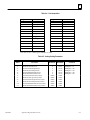
ÎÎ
GE Fanuc Automation
Programmable Control Products
t
Series 90
Programmable
Controllers
Flow Computer User’s Manual
GFK-0685A
September 1993
GFL–002
Warnings, Cautions, and Notes
as Used in this Publication
Warning
Warning notices are used in this publication to emphasize that hazardous voltages,
currents, temperatures, or other conditions that could cause personal injury exist in this
equipment or may be associated with its use.
In situations where inattention could cause either personal injury or damage to
equipment, a Warning notice is used.
Caution
Caution notices are used where equipment might be damaged if care is not taken.
Note
Notes merely call attention to information that is especially significant to understanding
and operating the equipment.
This document is based on information available at the time of its publication. While
efforts have been made to be accurate, the information contained herein does not
purport to cover all details or variations in hardware or software, nor to provide for
every possible contingency in connection with installation, operation, or maintenance.
Features may be described herein which are not present in all hardware and software
systems. GE Fanuc Automation assumes no obligation of notice to holders of this
document with respect to changes subsequently made.
GE Fanuc Automation makes no representation or warranty, expressed, implied, or
statutory with respect to, and assumes no responsibility for the accuracy, completeness,
sufficiency, or usefulness of the information contained herein. No warranties of
merchantability or fitness for purpose shall apply.
The following are trademarks of GE Fanuc Automation North America, Inc.
Alarm Master
CIMPLICITY
CIMPLICITY 90–ADS
CIMPLICITY PowerTRAC
CIMSTAR
GEnet
Genius
Genius PowerTRAC
Helpmate
Logicmaster
Modelmaster
ProLoop
PROMACRO
Series One
Series Three
Series Five
Copyright 1992–1993 GE Fanuc Automation North America, Inc.
All Rights Reserved
Series Six
Series 90
VuMaster
Workmaster
Preface
t
This manual provides the information necessary to install and use the Series 90 Flow
Computer which is a Series 90-30 or Series 90-70 PCM based MegaBasic program. This
program calculates the gas flow rate and volume for orifice meter applications in
accordance with the AGA3 standard using either the NX-19 or Standing Katz
supercompressibility methods.
t
Features and Benefits
Features and benefits of the Flow Computer are:
Feature
Benefit
PLC based
High integration flexibility leads to lower system costs.
Choice of Series 90-70 or Series 90-30 PLC
Series 90-30 facilitates low cost SCADA applications.
Series 90-70 for higher performance or VME applications.
Performs AGA3 gas calculations
Industry standard.
Supports NX19 or Standard Katz supercompressibility
Gas composition can be manually entered from an operator
interface.
Built-in operator interface
Lower system cost since no external operator interface or
computer is required to configure or monitor the Flow
Computer.
CIMPLICITY 90-ADS operator interface
Flow Computer operator interface can be customized to fit
application.
Contents of this Manual
Chapter 1. Introduction to the Flow Computer: Provides an introduction to the Series
90 Flow Computer.
Chapter 2. Installation and Configuration: Describes the hardware requirements and
how to install the hardware and software in your Series 90-30 or Series 90-70
Programmable Logic Controller system.
Chapter 3. Operation of the Flow Computer: Describes operation of the Flow Control
computer.
tMegaBasicis a trademark of Christopher Cochran.
GFK-0685
iii
Preface
Appendix A. Register Data Structure: A list of register data requirements for the Flow
Computer.
Appendix B. Diskette Files: List of diskette files included with the Flow Computer
software.
Appendix C. Config.Dat and Volume.Dat Files Default Value: A list of the default
values for these files.
Appendix D. Example of Ladder Logic: An example of the ladder logic which
implements the Flow Computer.
Related Publications:
Manual of Petroleum Measurement Standards, May 1991
Orifice Metering of Natural Gas, AGA Report No. 3, August 1985
Manual for the Determination of Supercompressibility Factors for Natural Gas. PAR Research
Project NX-19, published by AGA December 1962
Comparison Analysis of Orifice Metering of Natural Gas and Other Hydrocarbon Fluids. AGA
Transmission Measurement Committee Report No. 3A, dated 1985.
GFK-0262:
GFK-0356:
GFK-0263:
GFK-0265:
GFK-0466:
GFK-0467:
GFK-0401:
GFK-0255:
t
Series 90t-30 Programmable Controller Installation Manual
Logicmastert 90 Programming Software User’s Manual
Series 90t-70 Programmable Controller Reference Manual
Logicmastert 90-30 and 90-20 Programming Software User’s Manual
Series 90t-30/90-20 Programmable Controllers Reference Manual
WorkmasterR II PLC Programming Unit Guide to Operation
Series 90t Programmable Coprocessor Module and Support Software User’s
Series 90 -70 Programmable Controller Installation Manual
Manual
GFK-0487:
Series 90
t PCM Development Software (PCOP) User’s Manual
GEK-90817: OIT User’ Manual
GFK-0499:
GFK-0641:
R 90-ADS Alphanumeric Display System User’s Manual
CIMPLICITYR 90-ADS Alphanumeric Display System Reference Manual
CIMPLICITY
At GE Fanuc Automation, we strive to produce quality technical documentation. After
you have used this manual, please take a few moments to complete and return the
Reader ’s Comment Card located on the next page.
Henry A. Konat
Senior Technical Writer
iv
Series 90 Programmable Controllers Flow Computer User’s Manual - September 1993
GFK-0685
Contents
Chapter 1
Chapter 2
Chapter 3
Introduction to the Flow Computer . . . . . . . . . . . . . . . . . . . . . . . . . . .
1-1
Product Overview . . . . . . . . . . . . . . . . . . . . . . . . . . . . . . . . . . . . . . . . . . . . . . . .
System Configuration . . . . . . . . . . . . . . . . . . . . . . . . . . . . . . . . . . . . . . . . . . . . .
Definition of Terms . . . . . . . . . . . . . . . . . . . . . . . . . . . . . . . . . . . . . . . . . . . . . . .
1-1
1-2
1-3
Installation and Configuration . . . . . . . . . . . . . . . . . . . . . . . . . . . . . . .
2-1
What You Will Need . . . . . . . . . . . . . . . . . . . . . . . . . . . . . . . . . . . . . . . . . . . . . .
PLC Configuration . . . . . . . . . . . . . . . . . . . . . . . . . . . . . . . . . . . . . . . . . . . . . . . .
Register Size . . . . . . . . . . . . . . . . . . . . . . . . . . . . . . . . . . . . . . . . . . . . . . . . . .
Analog Inputs . . . . . . . . . . . . . . . . . . . . . . . . . . . . . . . . . . . . . . . . . . . . . . . . .
Relocating Analog Inputs . . . . . . . . . . . . . . . . . . . . . . . . . . . . . . . . . . . . . . . .
Software Installation . . . . . . . . . . . . . . . . . . . . . . . . . . . . . . . . . . . . . . . . . . . . . .
2-1
2-2
2-2
2-2
2-3
2-3
Initial Startup . . . . . . . . . . . . . . . . . . . . . . . . . . . . . . . . . . . . . . . . . . . . . . . . . . . .
Flow Computer Configuration . . . . . . . . . . . . . . . . . . . . . . . . . . . . . . . . . . . . . .
Process Units . . . . . . . . . . . . . . . . . . . . . . . . . . . . . . . . . . . . . . . . . . . . . . . . . .
Analog Inputs . . . . . . . . . . . . . . . . . . . . . . . . . . . . . . . . . . . . . . . . . . . . . . . . .
Register-Based Configuration . . . . . . . . . . . . . . . . . . . . . . . . . . . . . . . . . . . .
Register Data Structure . . . . . . . . . . . . . . . . . . . . . . . . . . . . . . . . . . . . . . . . .
COMREQ Instruction . . . . . . . . . . . . . . . . . . . . . . . . . . . . . . . . . . . . . . . . . . .
Ladder Logic Example . . . . . . . . . . . . . . . . . . . . . . . . . . . . . . . . . . .
CIMPLICITY 90-ADS . . . . . . . . . . . . . . . . . . . . . . . . . . . . . . . . . . . . . . . . . . .
Configuration Using the Local Operator Interface . . . . . . . . . . . . . . . . . .
Entering Configuration . . . . . . . . . . . . . . . . . . . . . . . . . . . . . . . . . . . . . . . . .
Time Display . . . . . . . . . . . . . . . . . . . . . . . . . . . . . . . . . . . . . . . . . . . . . . . . . .
Archiving the Flow Computer Configuration . . . . . . . . . . . . . . . . . . . . . . .
2-5
2-7
2-7
2-7
2-7
2-7
2-8
2-9
2-9
2-10
2-15
2-15
2-16
Operation . . . . . . . . . . . . . . . . . . . . . . . . . . . . . . . . . . . . . . . . . . . . . . . . .
3-1
Power Up . . . . . . . . . . . . . . . . . . . . . . . . . . . . . . . . . . . . . . . . . . . . . . . . . . . . . . . .
3-1
COMREQ Interrupt . . . . . . . . . . . . . . . . . . . . . . . . . . . . . . . . . . . . . . . . . . . . . . .
Calculations Interrupt . . . . . . . . . . . . . . . . . . . . . . . . . . . . . . . . . . . . . . . . . . . . .
3-1
3-2
RAM Disk Operation . . . . . . . . . . . . . . . . . . . . . . . . . . . . . . . . . . . . . . . . . . . . . .
Flow Computer OK . . . . . . . . . . . . . . . . . . . . . . . . . . . . . . . . . . . . . . . . . . . . . . .
Cold Start . . . . . . . . . . . . . . . . . . . . . . . . . . . . . . . . . . . . . . . . . . . . . . . . . . . . . . .
3-3
3-3
3-3
Warm Start . . . . . . . . . . . . . . . . . . . . . . . . . . . . . . . . . . . . . . . . . . . . . . . . . . . . . .
Resetting Volume . . . . . . . . . . . . . . . . . . . . . . . . . . . . . . . . . . . . . . . . . . . . . . . . .
3-3
3-3
Appendix A
Register Data Structure . . . . . . . . . . . . . . . . . . . . . . . . . . . . . . . . . . . . .
A-1
Appendix B
Diskette Files . . . . . . . . . . . . . . . . . . . . . . . . . . . . . . . . . . . . . . . . . . . . . .
B-1
Appendix C
Config.dat and Volume.dat Files Default Values . . . . . . . . . . . . . . .
C-1
Appendix D
Example Ladder Logic . . . . . . . . . . . . . . . . . . . . . . . . . . . . . . . . . . . . . .
D-1
GFK–0685A
Series90 Programmable Controllers Flow Computer User’s Manual - September 1993
v
Contents
Figure 1-1. Flow Computer System with Local Operator Interface . . . . . . . . . . . . . . . . . . . . . . . . . . . .
1-2
Figure 1-2. Flow Computer System with CIMPLICITY 90-ADS . . . . . . . . . . . . . . . . . . . . . . . . . . . . . . .
1-2
GFK–0685A
Series90 Programmable Controllers Flow Computer User’s Manual - September 1993
vi
Contents
Table 2-1. Engineering Units for Flow Computer Results . . . . . . . . . . . . . . . . . . . . . . . . . . . . . . . . . . . . .
2-11
Table A-1. Flow Computer Data Table . . . . . . . . . . . . . . . . . . . . . . . . . . . . . . . . . . . . . . . . . . . . . . . . . . . . .
A-1
Table A-2. Common Input Parameters . . . . . . . . . . . . . . . . . . . . . . . . . . . . . . . . . . . . . . . . . . . . . . . . . . . . .
A-1
Table A-3. Meter Configuration . . . . . . . . . . . . . . . . . . . . . . . . . . . . . . . . . . . . . . . . . . . . . . . . . . . . . . . . . .
A-2
Table A-4. Gas Composition . . . . . . . . . . . . . . . . . . . . . . . . . . . . . . . . . . . . . . . . . . . . . . . . . . . . . . . . . . . . .
A-3
Table A-5. Analog Scaling Parameters . . . . . . . . . . . . . . . . . . . . . . . . . . . . . . . . . . . . . . . . . . . . . . . . . . . . .
A-3
Table A-6. Output Data Block . . . . . . . . . . . . . . . . . . . . . . . . . . . . . . . . . . . . . . . . . . . . . . . . . . . . . . . . . . . .
A-4
Table C-1. Config.dat File Defaults . . . . . . . . . . . . . . . . . . . . . . . . . . . . . . . . . . . . . . . . . . . . . . . . . . . . . . . .
C-1
Table C-2. Volume.dat File Default . . . . . . . . . . . . . . . . . . . . . . . . . . . . . . . . . . . . . . . . . . . . . . . . . . . . . . . .
C-1
GFK–0685A
Series90 Programmable Controllers Flow Computer User’s Manual - September 1993
vii
restart lowapp ARestart oddapp: ARestarts for autonumbers that do not restart in
each chapter. figure bi level 1, reset table_big level 1, reset chap_big level 1, reset1
Lowapp Alwbox restart evenap:A1app_big level 1, resetA figure_ap level 1, reset
table_ap level 1, reset figure level 1, reset table level 1, reset these restarts
oddbox reset: 1evenbox reset: 1must be in the header frame of chapter 1. a:ebx, l 1
resetA a:obx:l 1, resetA a:bigbx level 1 resetA a:ftr level 1 resetA c:ebx, l 1 reset1
c:obx:l 1, reset1 c:bigbx level 1 reset1 c:ftr level 1 reset1 Reminders for
autonumbers that need to be restarted manually (first instance will always be 4)
let_in level 1: A. B. C. letter level 1:A.B.C. num level 1: 1. 2. 3. num_in level 1: 1. 2.
3. rom_in level 1: I. II. III. roman level 1: I. II. III. steps level 1: 1. 2. 3.
Chapter
1 Introduction to the Flow Computer
1
This chapter provides an introduction to the GE Fanuc Flow Computer for the Series
90-30 and Series 90-70 Programmable Logic Controllers.
Product Overview
The Series 90 Flow Computer is a Series 90-30 or Series 90-70 Programmable Coprocessor
Module (PCM) based Megabasic program (catalog number IC641SWP064) which
calculates the gas flow rate and volume for orifice meter applications in accordance with
the AGA3 standard using either the NX-19 or Standing Katz supercompressibility
methods. Gas composition can be manually entered using the operator interface. Up to
four orifice-type meters can be supported by the Flow Computer simultaneously.
The Flow Computer can be used with only one of two operator interfaces:
1.
Local operator interface only - The local operator interface can configure the Flow
Computer, and view the calculated results using seven built-in screens. PLC
registers are not used and ladder logic is unnecessary when the local operator
interface is used.
2.
CIMPLICITY 90-ADS operator interface only - there is no local operator interface.
The CIMPLICITY 90-ADS (Alphanumeric Display System) operator interface
communicates to the Flow Computer through the PLC registers. A set of
CIMPLICITY 90-ADS screens is provided on the flow computer diskette.
Note
Although the local operator interface and external operator interface
can be connected simultaneously, restrictions apply as listed below. The
local operator interface and external operator interface are not intended
to be used simultaneously.
The external operator interface cannot view configuration changes
made by the local operator interface.
The most recent configuration change from either the external operator
interface or the local operator interface takes precedence.
GFK-0685
1-1
1
System Configuration
Two typical Flow Computer systems are illustrated below. Figure 1-1 is a Flow Computer
system which uses the PCM local operator interface, while Figure 1-2 illustrates the use
of CIMPLICITY 90-ADS as an operator interface communicating to the Flow Computer
PCM through the PLC registers. The GE Fanuc Workmaster II (or IBM compatible)
computer is used to:
D
D
D
install Flow Computer diskette files to the PCM
to download PLC configuration and ladder logic
and to download ADS screens and configuration to the ADC.
ÎÎ
ÎÎ
ÎÎ
ÎÎ
Î
Î
ÎÎ
ÎÎ
ÎÎ
ÎÎ
ÎÎ
ÎÎ
Î
Î
Î
ÎÎ
Î
ÎÎ
ÎÎÎ
ÎÎ
ÎÎ
ÎÎ
Î
Î
Î
ÎÎ
Î
ÎÎ
ÎÎ
ÎÎ
ÎÎ
ÎÎ
Î
Î
ÎÎ
ÎÎ
Î
Î
ÎÎ
ÎÎ
ÎÎ
ÎÎ
Î
Î
Î
ÎÎ
Î
ÎÎ
ÎÎ
ÎÎ
ÎÎ
ÎÎ
Î
Î
Î
ÎÎ
Î
ÎÎ
ÎÎÎÎÎÎÎÎÎÎ
ÎÎÎÎÎÎÎÎÎÎ
ÎÎÎÎ
ÎÎÎÎÎÎÎÎÎÎ
ÎÎÎÎ
ÎÎÎÎÎÎÎÎÎÎ
ÎÎÎÎÎ
Î
ÎÎ
ÎÎÎÎÎÎÎÎÎ
Î
ÎÎÎÎÎÎÎÎÎÎ
ÎÎ
Î
ÎÎÎÎÎÎÎÎÎ
ÎÎÎÎÎÎÎÎÎÎ
ÎÎÎÎÎÎÎÎÎÎ ÎÎÎÎÎÎÎÎÎ
a45053
SERIES 90–3O
OR
SERIES 90–70
PLC
C P
P C
U M
WORKMASTER II
OIT
LOCAL OPERATOR INTERFACE
INSTALLATION
LOGICMASTER 90 SOFTWARE
PCOP SOFTWARE
Figure 1-1. Flow Computer System with Local Operator Interface
ÎÎ
ÎÎ
Î
ÎÎ
Î
ÎÎ
ÎÎ
Î
ÎÎ
Î
ÎÎÎ
ÎÎ
Î
ÎÎ
Î
ÎÎ
ÎÎ
Î
ÎÎ
Î
ÎÎ
ÎÎ
Î
ÎÎ
Î
ÎÎ
ÎÎ
Î
ÎÎ
Î
ÎÎ
ÎÎ
Î
ÎÎ
Î
ÎÎ
ÎÎ
Î
ÎÎ
Î
ÎÎ
ÎÎÎÎ
ÎÎÎ
ÎÎÎ
ÎÎ
ÎÎ
ÎÎÎÎÎÎÎÎÎ
ÎÎÎÎÎÎÎÎÎ
ÎÎÎÎÎÎÎÎ
ÎÎÎÎ
ÎÎÎÎÎÎÎÎÎ
ÎÎÎÎÎÎÎÎ
ÎÎÎÎ
ÎÎÎÎÎÎÎÎÎ
ÎÎÎÎÎÎÎÎ
ÎÎÎÎ
Î
ÎÎÎÎÎÎÎÎÎ
ÎÎÎÎÎÎÎÎ
ÎÎÎÎÎÎÎÎÎ
Î
Î
ÎÎÎÎÎÎÎÎÎ
ÎÎÎÎÎÎÎÎ
ÎÎÎÎÎÎÎÎÎ
ÎÎÎÎÎÎÎÎÎ
ÎÎÎÎÎÎÎÎ ÎÎÎÎÎÎÎÎÎ
a45052
SERIES 90–3O
OR
SERIES 90–70
PLC
C P A
P C D
U M C
WORKMASTER II
OIT
EXTERNAL OPERATOR INTERFACE
INSTALLATION
LOGICMASTER 90 SOFTWARE
PCOP SOFTWARE
Figure 1-2. Flow Computer System with CIMPLICITY 90-ADS
1-2
Series 90 Programmable Controllers Flow Computer User’s Manual - September 1993
GFK-0685
1
Definition of Terms
The following acronyms are used throughout this manual and are defined here for
clarity.
ADC
ADS
AGA
ASCII
BCD
COMREQ
CPU
EPROM
H
I/O
K
KB
LD
MB
OEM
PC
PCM
PCOP
PLC
PROM
PS
RAM
RLD
SCADA
UCDF
Alphanumeric Display Coprocessor
Alphanumeric Display System
American Gas Association
American National Standard Code for Information Interchange
Binary Coded Decimal
Communications Request (instruction)
Central Processing Unit
Erasable Programmable Read Only Memory
Hexadecimal
Input/Output
1024
Kilobyte (1024 bytes)
Ladder Diagram language (same as RLD)
Megabyte (1,048,576 bytes)
Original Equipment Manufacturer
Personal Computer, IBM compatible
Programmable Coprocessor Module
PCM development software
Programmable Logic Controller
Programmable Read Only Memory
Power Supply
Random Access Memory
Relay Ladder Diagram
Supervisory Control and Data Acquisition
User Configuration Data
For a complete definition of AGA terms relevant to the use of the Flow Computer, refer
to page 34 of the “Orifice Metering of Natural Gas” dated May 1991.
GFK-0685
Chapter 1 Introduction to the Flow Computer
1-3
Chapter
2 Installation and Configuration
2
section level 1 1
figure bi level 1
table_big level 1
This chapter describes hardware requirements, configuration requirements, and explains
how to install and start the Flow Computer.
What You Will Need
1.
A Series 90-30 or 90-70 PCM module. PCM Revision 2.50 or later firmware to
execute the Flow Computer program.
D
D
Series 90-30 PCM with 640K Bytes (catalog number IC693PCM311).
Series 90-70 PCM (catalog number IC697PCM711) with either a 256K Expansion
Memory board (catalog number IC697MEM717) or 512K Expansion Memory
board (catalog number IC697MEM719). (Note: The Flow Computer has been
configured for a 256K Expansion Memory board. If a 512K Expansion memory
board is used, the UCDF.CDF file supplied with the Flow Computer must be
changed using PCOP.)
2.
Flow Computer software diskettes (catalog number IC641SWP064).
3.
A computer for downloading the Flow Computer software files to the PCM. This
computer can be:
D
A GE Fanuc Workmaster II industrial computer or IBMRPS/2R (or compatible
Personal Computer).
D
D
An IBM PC-AT or compatible Personal Computer.
A Workmaster industrial computer or IBM PC-XT (or compatible Personal
Computer).
4.
Logicmaster 90 software.
5.
PCOP software (IC641SWP061) to configure and download software files to the PCM.
6.
(Optional) Alphanumeric Display Coprocessor module (IC697ADC701 for a Series
90-70 PLC; IC693ADC311 for a Series 90-30 PLC) and associated VT100 terminal.
7.
A cable is needed to connect the computer to the PCM. The cable selected depends
on which computer you are using. Connection is from the computer’s serial port to
port 1 on the PCM.
D
D
D
Workmaster II or IBM PS/2 - use PCM cable IC690CBL705
IBM PC-AT - use PCM cable IC690CBL701
IBM PC-XT - use PCM cable IC690CBL702
RIBM and PS/2 are registered trademarks of InternationalBusinessMachinesCorporation.
GFK-0685
2-1
2
A local operator interface VT100 compatible terminal is optional and can be connected to
port 2 on the PCM. The IC690CBL705 cable can be used for distances up to 10 feet. If
you need a longer cable, detailed information on cable connections for port 2 is specified
in Appendix A of the PCM and Support Software User’s Manual, GFK-255. The default
baud rate for port 2 is 19.2K. If hardware handshaking is selected but a local operator
interface is not connected to the PCM, change the handshake select to software
handshake. For other baud rates the PCM configuration file can be modified and
downloaded to the PCM using PCOP (PCM Development Software). For detailed
information on using PCOP, see the Series 90 PCM Development Software (PCOP)
User’s Manual, GFK-0487B, or later version.
The following VT100 compatible terminals have been tested and are recommended for
operation with the Flow Computer:
D
D
GE Fanuc color OIT (catalog number IC600KT512D)
DEC VT100
Other VT100 terminals (or terminal emulators) may be compatible with the Flow
Computer but have not been tested.
PLC Configuration
The requirements for configuring the PLC for operation of the Flow Computer are
described in this section.
Connect the Workmaster II programming computer to the Series 90-70 or Series 90-30
PLC programming port.
To configure the PLC for the Flow Computer PCM, enter the Logicmaster 90
Configuration package. Select a PCM for the slot in which the Flow Computer is to be
installed. Configure the PCM for “PCM CFG” mode, which will cause the Flow
Computer to use its on-board UCDF configuration file following a soft reset.
Register Size
If the local operator interface is being used, the PLC register table is not used and this
section can be skipped.
For Flow Computer register-based operation, the PLC register table must be sized to
assign a group of contiguous registers to the Flow Computer. The Flow Computer
register database size is 108 registers per meter, plus 8 registers for common meter
parameters. This means that for a four meter system, a total of 440 registers must be
allocated.
This group of registers can be located anywhere within the PLC register table. The
starting address is assigned with a ladder logic COMREQ instruction issued to the Flow
Computer which will be explained later.
Analog Inputs
Each Flow Meter requires three analog inputs to be operational, Static Pressure, Static
Temperature, and Differential Pressure. The Flow Computer reads the analog inputs
from the PLC periodically and calculates new results. The analog inputs for all four
2-2
Series 90 Programmable Controllers Flow Computer User’s Manual - September 1993
GFK-0685
2
meters is contiguous in the PLC %AI table starting at %AI1 and ending at %AI12. For
meter 1, Static Pressure is located in %AI1, Static Temperature in %AI2, and Differential
Pressure in %AI3. The same format is repeated for meters 2 through 4.
Relocating Analog Inputs
The %AI1 starting address can be changed by using the local operator interface System
screen as explained later under “Configuration Using the Local Operator Interface”.
Software Installation
The PCM development software package (PCOP) is used to install the Flow Computer
diskette files on the PCM RAM. See Appendix B for a description of these files. Use the
following steps for installing the Flow Computer software.
GFK-0685
1.
Connect the PCM programming cable from the Workmaster II computer to the Flow
Computer PCM port 1.
2.
Hard reset the PCM by depressing the pushbutton on the front of the module for at
least five seconds. Boot-up the Workmaster II computer. Invoke PCOP from either
the Logicmaster 90 main screen by pressing the F3 function key, or type PCOP at the
DOS prompt.
Chapter 2 Installation and Configuration
2-3
2
3.
The PCOP copyright screen will then be displayed. Press the Enter key, the Folder
screen is now displayed.
4.
Insert the Flow Computer diskette into the diskette drive on the Workmaster II
computer. Select the Flow Computer folder by typing a:\FLOW30.PCM or
a:\FLOW70.PCM, then press the ENTER key. The PCOP Main menu will now be
displayed.
A:\FLOW70.PCM
2-4
Series 90 Programmable Controllers Flow Computer User’s Manual - September 1993
GFK-0685
2
5.
Select F9, “Utility”
a:\FLOW70.PCM
6.
Select “Load” with the F2 key. Tab through the selections to the “Specify” mode,
then enter the first file to be loaded and type Return. Repeat this process until all
files from the following list have been loaded to the PCM:
AGA.PGM
CALC.CRN
OI.PGM
VT100_5.PGM
UCDF.CDF
CONFIG.DAT
VOLUME.DAT
Initial Startup
To startup the Flow Computer and check it for correct operation, connect an OIT or DEC
VT100 compatible terminal to port 2 on the PCM, stop the PLC, and do a soft reset (press
button for less than 5 seconds) of the PCM. At initial startup, the Flow Computer uses
the default configuration in its non-volatile RAM CONFIG.DAT file as listed in Appendix
C.
The copyright screen will appear for five seconds, followed by the results screen. A
status message “Flow Computer Not OK” may appear in the lower right corner of the
results screen if an analog input is out of range of the default analog scaling. This should
be ignored since analog input scaling has not yet been configured for the application.
To further verify Flow Computer operation, the ladder logic example folders (FLOW30E
and FLOW70E) provided with the Flow Computer may be loaded and executed. Refer
to the discussion of the ladder logic example under “COMREQ Instruction” later in this
GFK-0685
Chapter 2 Installation and Configuration
2-5
2
chapter. The Flow Computer PCM is expected to be in slot 2 for this example. Using
Logicmaster 90, load the appropriate folder to the PLC, set the PLC to Run mode, and
turn %T6 on to load the configuration registers and analog inputs. The calculated flow
rate shown on the local operator interface results screen should be 0.861 MMCF/HR for
all four meters.
If the Flow Computer does not startup at all, then PLC configuration as well as Flow
Computer hardware and software should be checked. Once the problem is corrected,
soft reset the Flow Computer.
If you get no results or unexpected results when you press the OIT function keys, your
OIT may need to be initialized. To do this, plug an IBM XT compatible keyboard into the
applicable connector on the back of your OIT. Press the Ctrl-1 key sequence on the
attached keyboard. The OIT Configuration menu will be displayed on the screen. Use
the following sequence to initialize the OIT:
select the LOCAL mode
press the Enter key
press the Esc key
enter the key sequence [>255u
press the Ctrl-1 key sequence
select the ONLINE mode
Remove the keyboard connection from the back of the OIT.
2-6
Series 90 Programmable Controllers Flow Computer User’s Manual - September 1993
GFK-0685
2
Flow Computer Configuration
The configuration parameters and options for configuring the Flow Computer are
discussed in the following paragraphs.
Process Units
There are two choices of process units documented for the AGA 3 standard, “IP” (USA)
and “SI” (International). This version of the Flow Computer product supports the IP
units only. Source code changes to the flow computer program are required to accept
input and display results in “SI” (International) units. To find the units used for a
particular input or output parameter of the Flow Computer, see page 34 of the AGA
report number 3 entitled “Orifice Metering of Natural Gas” referenced in the Related
Publications List in the Preface of this manual.
Analog Inputs
Each analog input must be a two’s-complement 16-bit value within the %AI 16-bit word.
If third-party VME analog modules are used, ladder logic may be needed to left-justify
or sign extend the data in the %AI input word to a full 16-bit value.
The Flow Computer provides programmable scaling that allows the analog inputs to be
converted from “counts” to process “units”. The scaling parameters are entered either
through the PLC registers or with the local operator interface.
Four parameters must be supplied for each of the analog inputs:
1.
Minimum and Maximum Counts - this is the maximum range of the %AI analog
input. The default values are 0 and 32000, respectively, corresponding to ranges 0 to
5V, 0 to 10V, and 0 to 20 ma. For a –10 to +10 volt input, it will be necessary to
change the Minimum Counts to –32000.
2.
Minimum and Maximum Units - these are the minimum and maximum process
values corresponding to the Minimum and Maximum Counts, respectively.
The default values for these parameters and their maximum ranges are listed in the
Register Data Structure (Appendix A) and in the CONFIG.DAT file (Appendix C).
Register-Based Configuration
If the PLC registers are to be used for configuration, they must be set up prior to starting
the Flow Computer. If PLC registers will not be used to configure the Flow Computer,
this discussion can be skipped by proceeding to the discussion under “Configuration
Using the Local Operator Interface”.
Register Data Structure
The Flow Computer may be configured from the PLC registers using Logicmaster 90
Configuration software, or from the CIMPLICITY 90-ADS product. A complete set of
ADS screens is provided on the Flow Computer diskette. If the CIMPLICITY 90-ADS
operator interface is used, ladder logic must be present in the PLC to issue a COMREQ
instruction to the PCM. This is further described in the discussion below under
“COMREQ Instruction”.
The Flow Computer register structure consists of 108 registers per meter, plus 8 registers
at the beginning of the database for information common to all meters. The database
format is illustrated in Appendix A.
GFK-0685
Chapter 2 Installation and Configuration
2-7
2
The Flow Computer requires only those registers needed for the number of meters
configured. For example, if two meters are configured, then the register database will
consume 8 + (2 x 10⁸), or 224 registers. The maximum number of registers used with 4
meters is 8 + (4 x 10⁸), or 440 registers. For convenience in retrofit applications, the
register database can be relocated anywhere in the PLC register table by specifying the
starting address through the COMREQ instruction.
COMREQ Instruction
Ladder logic is necessary to issue a COMREQ instruction to the Flow Computer to:
D
D
download the configuration registers to the Flow Computer, or
enable the Flow Computer to periodically write the calculated results to the PLC
registers.
The Flow Computer reads the PLC register configuration data and saves it in its
non-volatile RAM configuration file CONFIG.DAT whenever the PLC issues a COMREQ
instruction to the PCM. The COMREQ must specify a starting register address for a
group of register parameters which contain the register pointer to the Flow Computer
database.
An external operator interface can download new meter configuration to the PLC
registers, then cause the registers to be read by the Flow Computer by activating the
COMREQ instruction in one of the following ways:
D
by activating a one-shot contact placed in series with the COMREQ instruction. The
advantage of this method is higher performance since there is no continuous
COMREQ overhead.
D
by activating a COMREQ periodically, such as once every five seconds, through a
PLC timer. This is the method chosen for the ladder logic example in Appendix D
which must be used to operate the example ADS screens provided with the Flow
Computer. The advantage of this method is simplicity since the Host computer or
the external operator interface does not need to cause a one-shot triggered
COMREQ to occur after the configuration is changed in the registers. A
disadvantage of this method is that Flow Computer configuration cannot be
modified from the local operator interface since the next update from the Flow
Computer register database will overwrite any local operator interface changes.
Note
To avoid PCM mis-operation, the ladder logic should not excessively
burden the Flow Computer with COMREQs. Frequent (more than 1 per
second) COMREQs may lead to sluggish Flow Computer operator
interface response and may slow down the meter calculations to an
unacceptable level.
If COMREQs must be sent more often than once per second, use the “COMREQ Status”
flag located in the common parameters area of the Flow Computer database (see
Appendix A, Table A-2). After sending a COMREQ to the PCM, the ladder logic should
clear this flag. The next COMREQ should be issued only if the Flow Computer has
restored the flag to a one, indicating that the previous COMREQ has been received.
Note that the COMREQ Status flag will not be set until after a COMREQ has been
issued. Thus at power-up, or soft reset, the PCM must be “primed” with the first
COMREQ before the COMREQ Status will be set. A PCM power-up or soft reset can be
2-8
Series 90 Programmable Controllers Flow Computer User’s Manual - September 1993
GFK-0685
2
detected in ladder logic with a 5 second watchdog timer reset by the %T100 “Flow
Computer OK” flag as shown in the ladder logic example in Appendix D.
Ladder Logic Example
The ladder logic example shown in Appendix D is provided with the Flow Computer in
the FLOW30E and FLOW70E folders. This example downloads the configuration
registers and analog inputs to the Flow Computer once every five seconds. The values
correspond to those contained in the default CONFIG.DAT file shown in Appendix C.
The first 34 rungs load this configuration into the register data structure which starts at
%R500. These rungs only execute when the %T6 coil is manually set.
A Block Move instruction at rung 38 loads the seven registers required for the COMREQ
instruction starting at register 5. Register 11 contains the pointer to the Flow Computer
data structure, which is %R500.
The COMREQ instruction is fired by a periodic 5 second timer coil %T50 located at rung
37. The Flow Computer PCM is assumed to be in slot 2.
Rungs 35 and 36 are provided only for reference. They perform no function in the
ladder logic example. Rung 35 detects the COMREQ Status flag which indicates that the
previous COMREQ has been received by the Flow Computer. Rung 36 provides a five
second watchdog timer for the “Flow Computer OK” heartbeat located at %T100. The
watchdog output %Q1 will turn on if the Flow Computer heartbeat is not being
detected. These flags are reset in rungs 39 and 40.
CIMPLICITY 90-ADS
If CIMPLICITY 90-ADS is used, ladder logic must be present in the PLC to manage the
configuration download to the Flow Computer and the calculated results from the Flow
Computer to the PLC registers.
The ladder logic example in Appendix D can be used with the example ADS screens
provided on the Flow Computer diskette. Any configuration parameters changed in an
ADS screen will be downloaded to the Flow Computer from the PLC registers within 5
seconds. The register data structure starts at %R500. The register data structure starting
address can be changed. However, moving the register data structure will require the
ADS parameters with register pointers to be manually changed.
GFK-0685
Chapter 2 Installation and Configuration
2-9
2
Configuration Using the Local Operator Interface
Ladder logic is unnecessary if the local operator interface is being used for configuration.
The Flow Computer local operator interface consists of seven built-in screens which are
described below. These screens have the same “look and feel” as those provided for
CIMPLICITY 90-ADS. A Help screen is also provided. The local operator interface is
function key driven. Remember that the four configuration screens display parameters
for one meter at a time. The displayed meter number can be changed in the System
screen.
The local operator interface consists of the following seven screens.
1.
Title screen - this screen displays a copyright notice and the Flow Computer Revision
number for the first five seconds after startup.
GE FANUC FLOW COMPUTER
COPYRIGHT 1991 GE FANUC AUTOMATION NORTH AMERICA, INC.
Published in a limited, copyright sense and all rights,
including trade secret rights are reserved. Unauthorized
use of information or program is strictly prohibited.
Revision 1.01
2-10
Series 90 Programmable Controllers Flow Computer User’s Manual - September 1993
GFK-0685
2
2.
Results screen - this screen displays the calculated results. Since the configuration file
in the non-volatile PCM RAM is defaulted to four meters, the results screen should
be displaying the results for these meters soon after initial startup. There is no
operator input required in the results screen. A Series 90-70 PCM will update its
screen about once every two seconds with four meters configured. A Series 90-30
PCM with four meters will update about once every ten seconds. The units
displayed for the flow rate and volume results are as follows:
Table 2-1. Engineering Units for Flow Computer Results
Parameter
Flow/Hour
MMCF/Hr
Flow/Day
MMCF/Day
Volume
MCF
Meter # 1
ANALOG
PF
TF
HW
FLOW FACTORS:
Fb:
Fgr:
Ftb:
Y:
Fpb
Ftf
Fr:
Fpv:
Z Flowing:
FLOW RESULTS:
OFC
FLOW (MMCF/HR)
VOLUME (MCF)
FLOW (MMCF/DAY)
-F1-
GFK-0685
IP Units
889.31
96.50
24.73
5000.7980
1.2910
1.0000
1.00014
.98069
.96663
1.00031
1.0560
.00000
6465.7358
0.966781
1319.959455
23.20275
:SYSTEM :CONFIG : KATZ
Chapter 2 Installation and Configuration
Meter # 2
889.31
96.50
24.73
Meter # 3
889.31
96.50
24.73
5000.7980
1.2910
1.0000
1.00014
.98069
.96663
1.00031
1.0560
.00000
5000.7980
1.2910
1.0000
1.00014
.98069
.96663
1.00031
1.0560
.00000
Meter # 4
889.31
96.50
24.73
5000.7980
1.2910
1.0000
1.00014
.98069
.96663
1.00031
1.0560
.00000
6465.7358
0.966781
807.848322
23.20275
: NX19
6465.7358
6465.7358
0.966781
0.966781
797.292448
790.103399
23.20275
23.20275
6:07 FLOW COMPUTER OK
:SCALING:RESULTS: -F8- : -F9- : HELP
2-11
2
3.
System screen - this screen allows you to enter parameters which are not
meter-specific. The items which you can enter in this screen are:
Number of meters to be calculated - this is the number of meters which will be
periodically calculated. It can be set to zero to improve local operator interface
response time during initial setup.
Meter number to be displayed - this parameter is used to change the meter number
displayed in any of the other screens. For instance, in the Meter Configuration
screen, only the configuration for the current meter number will be displayed. To
select another meter, it is necessary to change the displayed meter number in the
System screen.
Analog input reference address - this is the beginning reference address of the
analog inputs in the %AI table in the PLC.
Reset all meter volumes at (HHMM)- this entry determines the time at which all
meter volumes will be reset on a daily basis. Entry is in HHMM (Hour/Minute)
format.
Reset volume for meter # - this is a one-shot reset of the selected meter’s volume.
SYSTEM CONFIGURATION
Number of meters to be calculated
: 4
Meter number to be displayed
: 1
Analog input reference address
: 1
Reset all meter volumes at
: 800
(HHMM)
Reset volume for meter #
EDIT
2-12
:SYSTEM
:CONFIG : KATZ
: 0
: NX19
6:10 FLOW COMPUTER OK
:SCALING:RESULTS: -F8- : -F9- : HELP
Series 90 Programmable Controllers Flow Computer User’s Manual - September 1993
GFK-0685
2
4.
Meter configuration screen - This screen allows configuration of most of the basic meter
parameters such as Pipe and Orifice diameter, as well as the supercompressibility
method, Katz or NX-19.
CONFIGURATION FOR METER # 1
SUPERCOMPRESSIBILITY
UNITS
TAP STYLE
TAP LOCATION
ORIFICE DIAMETER
TUBE DIAMETER
RELATIVE DENSITY
BAROMETRIC PRESSURE
BASE PRESSURE
BASE TEMPERATURE
EDIT
5.
:SYSTEM
:CONFIG : KATZ
(1=NX-19, 2=KATZ)
(0=IP)
(1=FLANGE, 2=PIPE)
(1=UPSTRM, 2=DOWNSTRM)
(INCHES or CENTIMETERS)
(INCHES or CENTIMETERS)
:
:
:
:
:
:
:
:
:
:
(PSIA or KPascal)
(PSIA or KPascal)
(FARENHEIT or CENTIGRADE)
: NX19
1
0
1
2
4.75
7.625
.6
14.7
15.02
60
6:10 FLOW COMPUTER OK
:SCALING:RESULTS: -F8- : -F9- : HELP
Katz supercompressibility screen - this screen allows entry of five parameters required
to configure the meter for Katz supercompressbility.
STANDING KATZ INPUT PARAMETERS FOR METER # 1
CRITICAL PRESS. (PSIA):
0
MOLE FRACTIONS
CARBON DIOXIDE:
HYDROGEN SULFIDE:
0
0
BASE SUPERCOMPRESSIBILITY:
EDIT
GFK-0685
:SYSTEM
CRITICAL TEMP. (deg R):
0
:CONFIG : KATZ
Chapter 2 Installation and Configuration
0
: NX19
6:05 FLOW COMPUTER OK
:SCALING:RESULTS: -F8- : -F9- : HELP
2-13
2
6.
NX-19 supercompressibility screen - This screen requires selection of one of the two
NX-19 supercompressibility methods. These methods are described in the “Manual
for the Determination of Supercompressibility Factors for Natural Gas” as referenced
in the Related Publications list in the preface in this manual. They are the “Standard
Method” for gas densities less than 0.75, and the “Methane- Gravity Method” for
densities greater than 0.75. The “Molal Analysis” and “Heating Value” methods are
not supported by the Flow Computer. The gas composition consists of all
compounds contained in the gas flow. The sum of these must be 1.0, however, a
warning message appears for five seconds if this is violated. Enter a mole fraction of
0 for any compound not present in the gas flow.
NX-19 GAS COMPOSITION FOR METER # 1
NX-19 METHOD
(0=STANDARD, 2=GRAVITY)
Hydrogen
Helium
Water
Carbon Monoxude
Nitrogen
Oxygen
Hydrogen Sulfide
Argon
Carbon Dioxide
:
:
:
:
:
:
:
:
:
0
0
0
0
0
.001
0
0
0
: 0
Methane
Ethane
Propane
Iso-Butane
N-Butane
Iso-Pentane
N-Pentane
N-Hexane
N-Heptane
N-Octane
N-Nonane
N-Decane
:
:
:
:
:
:
:
:
:
:
:
:
.005
0
0
0
0
0
0
0
0
0
0
0
WARNING: SUM OF MOLE FRACTIONS NOT EQUAL TO 1.0
6.06 FLOW COMPUTER OK
EDIT :SYSTEM
:CONFIG : KATZ : NX19 :SCALING:RESULTS: -F8- : -F9- : HELP
2-14
Series 90 Programmable Controllers Flow Computer User’s Manual - September 1993
GFK-0685
2
7.
Scaling screen - this screen allows the analog input scaling parameters to be modified.
If a minimum and maximum value are reversed, a status message appears for five
seconds.
ANALOG SCALING PARAMETERS FOR METER # 1
MAX
MIN
MAX
MIN
MAX
MIN
MAX
MIN
MAX
MIN
MAX
MIN
EDIT
STATIC PRESS.
STATIC PRESS.
STATIC TEMP.
STATIC TEMP.
DIFF. PRESS.
DIFF. PRESS.
STATIC PRESS.
STATIC PRESS.
STATIC TEMP.
STATIC TEMP.
DIFF. PRESS.
DIFF. PRESS.
:SYSTEM
(PSIA)
(PSIA)
(deg R)
(deg R)
(PSIA)
(PSIA)
(COUNTS)
(COUNTS)
(COUNTS)
(COUNTS)
(COUNTS)
(COUNTS)
:CONFIG : KATZ
:
:
:
:
:
:
:
:
:
:
:
:
: NX19
2000
0
100
0
100
0
32000
0
32000
0
32000
0
6:07 FLOW COMPUTER OK
:SCALING:RESULTS: -F8- : -F9- : HELP
Entering Configuration
To enter or change the value of a parameter on any of the screens, you must be in the
edit mode. To select the editor, press the F1 key. A reverse-video cursor will appear at
the first parameter. To scroll to a particular parameter, use the UP and DOWN arrow
cursor keys. To change the value of the parameter, type in the new number, then press
the Enter key.
The editor supports free-form entry of integers or real numbers, and correction of errors
by using the Back Space key. The Flow Computer performs range checking of all
configuration parameters during entry. If a parameter is rejected, an out-of-range
message will appear for five seconds, the original value will be restored, and you can
then re-enter the parameter. A table of the valid input range and usable significance for
each parameter is shown in Appendix A.
To exit the editor and save the new configuration, press the F1 key again, or select
another screen using the appropriate function key.
Note
The screen status message “Flow Computer OK” is not updated while in
the edit mode. When editing has been completed, the message will be
updated with the new Flow Computer status. The Flow Computer OK
flag in %T100 is updated while in the edit mode.
Time Display
For convenience, the time is periodically read from the PLC and displayed in the
Hour/Minute (HH:MM) format at the lower right of the screen.
GFK-0685
Chapter 2 Installation and Configuration
2-15
2
Archiving the Flow Computer Configuration
The Flow Computer configuration can be archived to diskette once it has been entered
or updated. Save the CONFIG.DAT file from the Flow Computer PCM to a hard disk or
diskette file using the PCOP utility. The procedure for using PCOP to save files is similar
to that used earlier during Software Installation to load files to the PCM, except that
“Save” instead of “Load” must be selected.
2-16
Series 90 Programmable Controllers Flow Computer User’s Manual - September 1993
GFK-0685
Chapter
3 Operation
3
section level 1 1
figure bi level 1
table_big level 1
This chapter describes the operating features of the Flow Computer.
Power Up
The Flow Computer can be started by pressing the PCM soft reset key or by cycling
power to the PLC. On start-up the Flow Computer restores the meter configuration and
last calculated volume from its non-volatile RAM, then performs calculations on a
periodic basis.
If a configuration parameter or analog input is out of range, the status message “Flow
Computer Not OK” will appear at the lower right corner of the screen, which means
that calculations have been halted for the meter that has an error. After the fault is
corrected, the Flow Computer will automatically clear the diagnostic and resume
calculations for that meter.
Following a soft reset or power cycle, the Flow Computer executes the following detailed
sequence:
1.
It reads the configuration and volume files from the non-volatile disk. This is further
described in the RAM Disk Operation.
2.
It defines two interrupts, COMREQ and a 2.5 second timer. The COMREQ is used
to inform the Flow Computer that new register configuration is available. The 2.5
second timer is used to execute the next meter’s calculations.
3.
The operator interface background task is then entered and continuously executed.
The first screen displayed on the local operator interface is the copyright screen.
This is displayed for five seconds then the Results screen is displayed. This screen
displays the calculated results. No operator input is required in the Results screen.
Screen operation following the copyright screen is described in the Local Operator
Interface section of Chapter 2, Installation and Configuration. To exit the Results
screen and enter a configuration screen, select the function key for the screen you
want to enter. Once the local operator interface starts, it continuously updates the
current screen, interrupted only by a COMREQ instruction or timer interrupt.
COMREQ Interrupt
Once power-up initialization is completed, the Flow Computer will continuously execute
the local operator interface background task when it is not servicing a COMREQ or
timer interrupt.
GFK-0685
3-1
3
A COMREQ interrupt will be received whenever a COMREQ instruction is executed in
the PLC ladder logic. The COMREQ specifies a register pointer which will be used to
access the Flow Computer register database on the next calculation interrupt. Once a
COMREQ has been received by the Flow Computer, it reads all of the configuration
registers for each meter one time. The Flow Computer will not read the PLC registers
again until another COMREQ interrupt is received. Once a COMREQ has been issued,
the Flow Computer will continue to update the PLC register results until a soft or hard
reset or power cycle occurs.
Range checking is done on a configuration that is downloaded via a COMREQ. If an
out-of-range parameter is downloaded, it will be ignored. The status message “Flow
Computer Not OK” will appear on the local operator interface, and the Flow Computer
OK flag in %T100 will be set to 0. This diagnostic is automatically cleared when the
out-of-range register(s) is corrected and a new COMREQ instruction executed.
Calculations Interrupt
A calculations interrupt occurs every 2.5 seconds. This interrupt causes the meter
configuration to be read from the PLC (if a fresh COMREQ has occurred) and analog
inputs to be read from the PLC, and results to be calculated. Results will be stored in the
PLC registers if any COMREQs have been received since Flow Computer startup. The
flow volume is saved in non-volatile RAM so that it can be restored following a power
interruption or soft reset. Each timer interrupt processes only one meter. Calculations
for all meters proceed in a round robin fashion, i.e., meter 1 on the first interrupt, meter
2 on the second interrupt, etc. In a four meter system, each meter will be calculated once
every 10 seconds.
The frequency of the calculations was selected to be once every 2.5 seconds based on
the performance of a Series 90-30 PCM. For the Series 90-30 PCM, the time required by
the Flow Computer to process one meter ranges from 1.02 seconds with no COMREQs
to 1.47 seconds with COMREQs. This leaves about 1 second out of every 2.5 second
period for the local operator interface background task to update the screen and respond
to the keyboard. In a Series 90-70 PCM, the meter processing time ranges from .45
seconds with no COMREQ instructions to .62 seconds with COMREQ instructions. This
leaves about 1.8 seconds out of every 2.5 second period for the local operator interface
background task to update the screen and respond to the keyboard.
When faster calculations are required, it may be possible to increase the calculation
frequency by decreasing the timer period below 2.5 seconds. The Calculation Time is
saved in the PLC registers each calculation pass and can be viewed with Logicmaster 90.
It is stored in the Common Parameters section of the register table (see Appendix A). If
the Calculation Time is significantly below 2.5 seconds, the calculation frequency can be
increased by editing the AGA.PGM source code line “METER_CALC_PERIOD = 2500”
and changing the value from 2500 milliseconds to some lower value.
Note
If a local operator interface is being used, be careful not to set the
interrupt period too low, otherwise no time may be left to service the
local operator interface. This is noticeable by a screen which appears to
be sluggish or dead, even though the calculations continue.
3-2
Series 90 Programmable Controllers Flow Computer User‘s Manual - September 1993
GFK-0685
3
RAM Disk Operation
The Flow Computer non-volatile RAM data storage consists of a CONFIG.DAT and
VOLUME.DAT file. Default data files are supplied with the Flow Computer diskette
which must be loaded to the PCM before initial startup. The default values are shown in
Appendix C.
On startup, the CONFIG.DAT and VOLUME.DAT files are restored from the PCM
non-volatile RAM. If a COMREQ occurs, a local operator interface screen is exited or the
editor is exited, the CONFIG.DAT file is updated with the new configuration. The
VOLUME.DAT file is updated at the end of the calculation interrupt with the new
calculated meter volume.
Flow Computer OK
The Flow Computer OK flag at %T100 is a heartbeat from the PCM, which when set
indicates that all parameters are within range and that the Flow Computer is
operational. It is updated each time a meter’s calculations are completed. If an out of
range condition exists in either the register parameters or the analog inputs, it is reset.
The update frequency is equal to the METER_CALC_PERIOD (2.5 seconds). A
watchdog timer can be used to sense Flow Computer OK as illustrated by the ladder
logic in Appendix D. If it is necessary to change the location of the Flow Computer OK
flag from %T100, use the Megabasic editor (or the Basic87.exe program provided with
PCOP) to edit the line FLOC$=“%T100” in the AGA.PGM source file.
Cold Start
When the Flow Computer is started for the first time by a soft reset, hard reset, or power
cycle, the volume will equal zero in the VOLUME.DAT file. Within twenty seconds, the
Flow Computer will begin calculating a flow rate and volume based on the configuration
in the CONFIG.DAT file, and the analog values in the PLC %AI table.
Warm Start
By definition, the only difference between a cold start and warm start is that the volume
parameter is zero at a cold start. On a warm start, the volume parameter is non-zero
and the Flow Computer will begin accumulating volume from there. To reset the
volume to zero, see “Resetting Volume” below.
Resetting Volume
There is an automatic volume reset which takes place once each day at the time specified
by the Reset Time parameter in the System screen. Volume can also be reset manually
by selecting the meter number in the System screen parameter “Reset volume for meter
number”.
The volume for all meters can also be cleared by reloading the VOLUME.DAT file from
diskette to the Flow Computer PCM, then restarting the Flow Computer.
GFK-0685
Chapter 3 Operation
3-3
Appendix A Register Data Structure
A
Table A-1. Flow Computer Data Table
Block Name
Common Parameters
Meter 1 Configuration
Meter 1 Gas Composition
Meter 1 Scaling Parameter
Meter 1 Output Data
Meter 2 Configuration
Meter 2 Gas Composition
Meter 2 Scaling Parameters
Meter 2 Output Data
Meter 3 Configuration
Meter 3 Gas Composition
Meter 3 Scaling Parameters
Meter 3 Output Data
Meter 4 Configuration
Meter 4 Gas Composition
Meter 4 Scaling Parameters
Meter 4 Output Data
Offset (words)
Length (words)
0
8
40
72
84
116
148
180
192
224
256
288
300
332
364
396
408
8
32
32
12
32
32
32
12
32
32
32
12
32
32
32
12
32
Table A-2. Common Input Parameters
GFK-0685
Register Offset
Parameter
Minimum
+0
+1
+2
+3/7
Number of Meters
COMREQ Status
Calculation Time (ms)
Not Used
1
0 = Not Ready
0
Maximum
4
1 = Ready
–
Comment
To PCM
From PCM
From PCM
A-1
A
Table A-3. Meter Configuration
Register
Offset
Parameter
+0
+1
+2
+3
+4
+5
+6
+7
+8
+9
+10
+11
+12
+13
+14
+15
+16
+17/18
+19/20
+21
+22
+23
+24
+25/31
Not Used
Not Used
Not Used
Units
Not Used
Tap Style
Tap Location
SupercompressibilityMethod
Density
Barometric Pressure
Base Pressure
Base Temperature
Orifice Diameter
Tube Diameter
Not Used
Not Used
Not Used
Critical Pressure
Critical Temperature
Mole Fraction CO2
Mole Fraction H2S
BaseCompressibility
NX-19 Method
Not Used
A-2
Minimum
Maximum
0 = USA
1 = (not used)
1 = Flange
1 = Upstream
1 = NX-19
0
0
0
0
.001
.001
2 = Pipe
2 = Downstream
2 = KATZ
1.0000
655.35
65.535
655.35
65.535
65.535
0
0
0
0
0
0
655.35
655.35
1.0
1.0
1.0
2
Comment
Multiplier = 10,000
Multiplier = 100
Multiplier = 1000
Multiplier = 100
Multiplier = 1000
Multiplier = 1000
Double Precision, Multiplier = 100
Double Precision, Multiplier = 100
Multiplier = 10,000
Multiplier = 10,000
Multiplier = 10,000
Series 90 Programmable Controllers Flow Computer User‘s Manual - September 1993
GFK-0685
A
Table A-4. Gas Composition
Register Offset
Compound
Register Offset
Compound
+0
Undefined
+12
Propane
+1
Hydrogen
+13
Iso-Butane
+2
Helium
+14
N-Butane
+3
Water
+15
Iso-Pentane
+4
Carbon Monoxide
+16
N-Pentane
+5
Nitrogen
+17
N-Hexane
+6
Oxygen
+18
N-Heptane
+7
HydrogenSulfide
+19
N-Octane
+8
Argon
+20
N-Nonane
+9
Carbon Dioxide
+21
N-Decane
+10
Methane
+22/31
Not Used
+11
Ethane
Note: min=0, max =1.0000, register multiplier is 10,000
Table A-5. Analog Scaling Parameters
Register
Offset
+0
+1
+2
+3
+4
+5
+6
+7
+8
+9
+10
+11
GFK-0685
Parameter
Maximum Static Pressure
Minimum Static Pressure
Maximum Static Temperature
Minimum Static Temperature
Maximum Differential Pressure
Minimum Differential Pressure
Maximum Static Pressure (counts)
Minimum Static pressure (counts)
Maximum Static Temperature(counts)
Minimum Static Temperature(counts)
Maximum Differential Pressure (counts)
Minimum Differential Pressure (counts)
Appendix A Register Data Structure
Minimum
Maximum
0
0
0
0
0
0
–32000
–32000
–32000
–32000
–32000
–32000
6553.5
6553.5
655.35
655.35
655.35
655.35
32000
32000
32000
32000
32000
32000
Comment
Multiplier = 10
Multiplier = 10
Multiplier = 100
Multiplier = 100
Multiplier = 100
Multiplier = 100
A-3
A
Table A-6. Output Data Block
A-4
Register Offset
Parameter
+0
+1
+2
+3
+4
+5
+6
+7
+8
+9
+10
+12
+14
+16
+18/31
Density Factor
Pressure Base Factor
Temperature Base Factor
Flow Temperature Factor
Gas Exp. Factor
Reyn. Number Factor
SupercompressibilityFactor
FlowingCompressibility
Basic Orifice Factor
Unused
Orifice Flow Const.
Flow per Hour
Volume
Flow per Day
Unused
Comment
Multiplier = 10000
Multiplier = 10000
Multiplier = 10000
Multiplier = 10000
Multiplier = 10000
Multiplier = 10000
Multiplier = 10000
Multiplier = 10000
Multiplier = 10000
Double Precision, Multiplier = 10000
Double Precision,MMCF/HR
Double Precision, MCF or 103M
Double Precision,MMCF/DAY
Series 90 Programmable Controllers Flow Computer User‘s Manual - September 1993
GFK-0685
Appendix B Diskette Files
section level 1 1
figure_ap level 1
table_ap level 1
B
The FLOW30.PCM and FLOW70.PCM subdirectories contain the Flow Computer
application program and data files. Following is a list of these files.
GFK-0685
AGA.PGM
The AGA.PGM file is a PCM MegaBasic source file that contains the
upper level Flow Computer procedures.
CALC.CRN
The CALC.CRN file contains all of the calculation procedures called
by the Flow Computer application program. The calculations procedures cannot be viewed or modified.
OI.PGM
The OI.PGM file is a PCM MegaBasic source file that contains the
local operator interface procedures.
VT100_5.PGM
The VT100_5.PGM file is a PCM MegaBasic source file that contains
utility functions called by the Flow Computer application program.
UCDF.CDF
The UCDF.CDF file is a data file that contains the PCM user configuration data. The values are set to those required for the Flow Computer application.
CONFIG.DAT
The CONFIG.DAT file is a data file that contains the default Flow
Computer configuration. The configuration is changed by the user
to those required by the application.
VOLUME.DAT
The VOLUME.DAT file is a data file containing the current volume
for all meters. The default value is zero.
B-1
B
The ADS subdirectory contains a set of example Flow Computer ADS screens.
AGA.ALM
The AGA.ALM file contains the Flow Computer alarm definitions.
AGA.CFG
The AGA.CFG file contains the Flow Computer ADS configuration
data including the PLC data sources.
AGA1.SCN
The AGA1.SCN file contains the Flow Computer ADS title screen definitions.
AGA2.SCN
The AGA2.SCN file contains the Flow Computer ADS results screen
definitions.
AGA3.SCN
The AGA3.SCN file contains the Flow Computer ADS system screen
definitions.
AGA4.SCN
The AGA4.SCN file contains the Flow Computer ADS meter configuration screen definitions.
AGA5.SCN
The AGA5.SCN file contains the Flow Computer ADS Katz supercompressibility screen definitions.
AGA6.SCN
The AGA6.SCN file contains the Flow Computer ADS NX-19 supercompressibility screen definitions.
AGA7.SCN
The AGA7.SCN file contains the Flow Computer ADS title screen definitions.
The FLOW30E and FLOW70E subdirectories contain the example Logicmaster 90 folder
files for the Series 90-30 and Series 90-70, respectively.
B-2
Series 90 Programmable Controllers Flow Computer User’s Manual - September 1993
GFK-0685
Appendix C Config.dat and Volume.dat Files Default
Values
C
section level 1 1
figure_ap level 1
table_ap level 1
The two tables in this appendix list the default values for the Config.dat and Volume.dat
files.
Table C-1. Config.dat File Defaults
Parameter
Number of Meters
%AI Reference
Volume Reset Time
Units
Tap Style
Tap Location
SupercompressibilityMethod
Density
Barometric Pressure
Base Pressure
Base Temperature
Orifice Diameter
Tube Diameter
Maximum Static Pressure
Minimum Static Pressure
Maximum Static Temperature
Minimum Static Temperature
Maximum Differential Pressure
Minimum Differential Pressure
NX-19 Method
Nitrogen
Carbon Dioxide
Other Compounds
Value
4
1
800 (8 AM)
0 (IP)
1 (Flange)
2 (Downstream)
1 (NX-19)
.6
14.7
15.02
60
4.75
7.625
2000.0
0
100.00
0
100.00
0
0 (standard)
.001
.005
0
Table C-2. Volume.dat File Default
Parameter
Volume
GFK-0685
Value
0
C-1
Appendix D Example Ladder Logic
section level 1 1
figure_ap level 1
table_ap level 1
D
This appendix provides an example of the ladder logic for the Series 90–70 Flow
Computer. For a description of this ladder logic, see ”Ladder Logic Example” in Chapter
2, Installation and Configuration.
01–20–92
10:40
GE FANUC SERIES 90–70 DOCUMENTATION (v3.03)
FLOW COMPUTER LADDER LOGIC EXAMPLE
GGGG EEEEE
G
E
G GGG EEEE
G
G E
GGG EEEEE
AAA
A
A
AAAAA
A
A
A
A
U
U
U
U
U TTTTT OOO
U
T
O
O
U
T
O
O
U
T
O
O
UUU
T
OOO
FFFFF
F
FFF
F
F
M
M
MM MM
M M M
M
M
M
M
AAA
A
A
AAAAA
A
A
A
A
N
N
N
N
N N N
N NN
N
N
Page
1
U
U
U
U
U CCCC
U C
U C
U C
UUU
CCCC
AAA TTTTT IIIII OOO
A
A
T
I
O
O
AAAAA
T
I
O
O
A
A
T
I
O
O
A
A
T
IIIII OOO
N
N
NN N
N N N
N NN
N
N
(****************************************************************************)
(*
*)
(*
Program: FLOW70E
*)
(*
*)
(*
PLC PROGRAM ENVIRONMENT
HIGHEST REFERENCE USED
*)
(*
––––––––––––––––––––––––––
––––––––––––––––––––––––––
*)
(*
INPUT (%I):
512
INPUT:
NONE
*)
(*
OUTPUT (%Q):
512
OUTPUT: %Q00002
*)
(*
INTERNAL (%M): 2048
INTERNAL:
NONE
*)
(*
TEMPORARY (%T):
256
TEMPORARY: %T00100
*)
(*
PROGRAM REGISTER (%P): NONE
PROGRAM REGISTER:
NONE
*)
(*
REGISTER (%R): 2048
REGISTER: %R00907
*)
(*
ANALOG INPUT (%AI):
64
ANALOG INPUT: %AI0012
*)
(*
ANALOG OUTPUT (%AQ):
64
ANALOG OUTPUT:
NONE
*)
(*
*)
(*
PROGRAM SIZE (BYTES):
2000
*)
(*
*)
(*
*)
(****************************************************************************)
Program: FLOW70E
GFK-0685
C:\FLOW70E
D-1
D
01–20–92
10:40
GE FANUC SERIES 90–70 DOCUMENTATION (v3.03)
FLOW COMPUTER LADDER LOGIC EXAMPLE
Page
2
(****************************************************************************)
(*
*)
(*
PROGRAM BLOCK: _MAIN
*)
(*
*)
(*
*)
(*
PROGRAM REGISTER (%P) MEMORY SIZE (BYTES):
0
*)
(*
PROGRAM BLOCK SIZE (BYTES): 1939
*)
(*
DECLARATIONS (ENTRIES):
58
*)
(*
*)
(*
*)
(*
HIGHEST REFERENCE USED
*)
(*
–––––––––––––––––––––––––––––
*)
(*
*)
(*
INPUT (%I):
NONE
*)
(*
OUTPUT (%Q): %Q00002
*)
(*
INTERNAL (%M):
NONE
*)
(*
TEMPORARY (%T): %T00100
*)
(*
LOCAL REGISTER (%L):
NONE
*)
(*
PROGRAM REGISTER (%P):
NONE
*)
(*
REGISTER (%R): %R00907
*)
(*
ANALOG INPUT (%AI): %AI0012
*)
(*
ANALOG OUTPUT (%AQ):
NONE
*)
(*
*)
(*
*)
(****************************************************************************)
Program: FLOW70E
D-2
C:\FLOW70E
Block: _MAIN
Series90 Programmable Controllers Flow Computer User’s Manual - September 1993
GFK-0685
D
01–20–92
10:41
GE FANUC SERIES 90–70 DOCUMENTATION (v3.03)
FLOW COMPUTER LADDER LOGIC EXAMPLE
|[ START OF LD PROGRAM FLOW70E ]
(*
|
|[
VARIABLE DECLARATIONS
]
|
|[
PROGRAM BLOCK DECLARATIONS
]
|
|[
INTERRUPTS
]
|
|[
START OF PROGRAM LOGIC
]
|
| < RUNG 5 >>
|
|%T00006 –––––
|––] [–––|MOVE |–
|
| INT |
|
|
|
| CONST –|IN Q|–D_BASE
| +00500 | LEN |
|
|00001|
|
–––––
|
| < RUNG 6 >>
|
|%T00006 –––––
–––––
|––] [–––|MOVE_|–––––––––––––––––|MOVE_|––
|
| INT |
| INT | –
|
|
|
|
|
| CONST –|IN Q|–NO_MTRS CONST –|IN Q|– UNITS
| +00004 | LEN |
+00000 | LEN |
|
|00001|
|00001|
|
–––––
–––––
|
| < RUNG 7 >>
|
|%T00006 –––––
–––––
|––] [–––|MOVE_|–––––––––––––––––|MOVE_|––
|
| INT |
| INT |
|
|
|
|
|
| CONST –|IN Q|–TAPSTYL CONST –|IN Q|–TAP_LOC
| +00001 | LEN |
+00002 | LEN |
|
|00001|
|00001|
|
–––––
–––––
|
| < RUNG 8 >>
|
|%T00006 –––––
–––––
|––] [–––|MOVE_|–––––––––––––––––|MOVE_|––
|
| INT |
| INT |
|
|
|
|
|
| CONST –|IN Q|– SUPER
CONST –|IN Q|–DENSITY
| +00001 | LEN |
+06000 | LEN |
|
|00001|
|00001|
|
–––––
–––––
|
Program: FLOW70E
GFK-0685
AppendixD Example Ladder Logic
C:\FLOW70E
Page
3
*)
Block: _MAIN
D-3
D
01–20–92
10:41
GE FANUC SERIES 90–70 DOCUMENTATION (v3.03)
FLOW COMPUTER LADDER LOGIC EXAMPLE
Page
4
| < RUNG 9 >>
|
|%T00006 –––––
|––] [–––|MOVE |–
|
| INT |
|
|
|
| CONST –|IN Q|–BARPRES
| +01470 | LEN |
|
|00001|
|
–––––
|
| < RUNG 10 >>
|
|%T00006 –––––
–––––
|––] [–––|MOVE_|–––––––––––––––––|MOVE_|––
|
| INT |
| INT |
|
|
|
|
|
| CONST –|IN Q|–BASE_P
CONST –|IN Q|–BASE_T
| +15020 | LEN |
+06000 | LEN |
|
|00001|
|00001|
|
–––––
–––––
|
| < RUNG 11 >>
|
|%T00006 –––––
–––––
|––] [–––|MOVE_|–––––––––––––––––|MOVE_|––
|
| INT |
| INT |
|
|
|
|
|
| CONST –|IN Q|–ORIFDIA CONST –|IN Q|–TUBEDIA
| +04750 | LEN |
+07625 | LEN |
|
|00001|
|00001|
|
–––––
–––––
|
| < RUNG 12 >>
|
|%T00006 –––––
–––––
|––] [–––|MOVE_|–––––––––––––––––|MOVE_|––
|
| INT |
| INT |
|
|
|
|
|
| CONST –|IN Q|–CRIT_P1 CONST –|IN Q|–CRIT_P2
| +00000 | LEN |
+00000 | LEN |
|
|00001|
|00001|
|
–––––
–––––
|
| < RUNG 13 >>
|
|%T00006 –––––
–––––
|––] [–––|MOVE_|–––––––––––––––––+MOVE_|––
|
| INT |
| INT |
|
|
|
|
|
| CONST –|IN Q|–CRIT_T1 CONST –|IN Q|–CRIT_T2
| +00000 | LEN |
+00000 | LEN |
|
|00001|
|00001|
|
–––––
–––––
Program: FLOW70E
D-4
C:\FLOW70E
Block: _MAIN
Series90 Programmable Controllers Flow Computer User’s Manual - September 1993
GFK-0685
D
01–20–92
10:42
GE FANUC SERIES 90–70 DOCUMENTATION (v3.03)
FLOW COMPUTER LADDER LOGIC EXAMPLE
Page
5
| < RUNG 14 >>
|
|%T00006 –––––
–––––
|––] [–––|MOVE_|–––––––––––––––––|MOVE_|––
|
| INT |
| INT |
|
|
|
|
|
| CONST –|IN Q|–KATZCO2 CONST –|IN Q|–KATZH2S
| +00000 | LEN |
+00000 | LEN |
|
|00001|
|00001|
|
–––––
–––––
|
| < RUNG 15 >>
|
|%T00006 –––––
–––––
|––] [–––|MOVE_|–––––––––––––––––|MOVE_|––
|
| INT |
| INT |
|
|
|
|
|
| CONST –|IN Q|–BASECOM CONST –|IN Q|–NXMTHD
| +00000 | LEN |
+00000 | LEN |
|
|00001|
|00001|
|
–––––
–––––
|
| < RUNG 16 >>
|
|%T00006 –––––
–––––
|––] [–––|MOVE_|–––––––––––––––––|MOVE_|––
|
| INT |
| INT |
|
|
|
|
|
| CONST –|IN Q|–HYDROGN CONST –|IN Q|–HELIUM2
| +00000 | LEN |
+00000 | LEN |
|
|00001|
|00001|
|
–––––
–––––
|
| < RUNG 17 >>
|
|%T00006 –––––
–––––
|––] [–––|MOVE_|–––––––––––––––––|MOVE_|––
|
| INT |
| INT |
|
|
|
|
|
| CONST –|IN Q|– H2O
CONST –|IN Q|– CO
| +00000 | LEN |
+00000 | LEN |
|
|00001|
|00001|
|
–––––
–––––
|
| < RUNG 18 >>
|
|%T00006 –––––
–––––
|––] [–––|MOVE_|–––––––––––––––––|MOVE_|––
|
| INT |
| INT |
|
|
|
|
|
| CONST –|IN Q|–NITROGN CONST –|IN Q|–OXYGEN
| +00000 | LEN |
+00000 | LEN |
|
|00001|
|00001|
|
–––––
–––––
Program: FLOW70E
GFK-0685
AppendixD Example Ladder Logic
C:\FLOW70E
Block: _MAIN
D-5
D
01–20–92
10:42
GE FANUC SERIES 90–70 DOCUMENTATION (v3.03)
FLOW COMPUTER LADDER LOGIC EXAMPLE
Page
6
| < RUNG 19 >>
|
|%T00006 –––––
–––––
|––] [–––|MOVE_|–––––––––––––––––|MOVE_|––
|
| INT |
| INT |
|
|
|
|
|
| CONST –|IN Q|– H2S
CONST –|IN Q|– ARGON
| +00000 | LEN |
+00000 | LEN |
|
|00001|
|00001|
|
–––––
–––––
|
| < RUNG 20 >>
|
|%T00006 –––––
–––––
|––] [–––|MOVE_|–––––––––––––––––|MOVE_|–
|
| INT |
| INT |
|
|
|
|
|
| CONST –|IN Q|– CO2
CONST –|IN Q|–METHANE
| +00000 | LEN |
+00000 | LEN |
|
|00001|
|00001|
|
–––––
–––––
|
| < RUNG 21 >>
|
|%T00006 –––––
–––––
|––] [–––|MOVE_|–––––––––––––––––|MOVE_|––
|
| INT |
| INT |
|
|
|
|
|
| CONST –|IN Q|–ETHANE
CONST –|IN Q|–PROPANE
| +00000 | LEN |
+00000 | LEN |
|
|00001|
|00001|
|
–––––
–––––
|
| < RUNG 22 >>
|
|%T00006 –––––
–––––
|––] [–––|MOVE_|–––––––––––––––––|MOVE_|––
|
| INT |
| INT |
|
|
|
|
|
| CONST –|IN Q|–ISOBUT
CONST –|IN Q|–NBUTANE
| +00000 | LEN |
+00000 | LEN |
|
|00001|
|00001|
|
–––––
–––––
|
| < RUNG 23 >>
|
|%T00006 –––––
–––––
|––] [–––|MOVE_|–––––––––––––––––|MOVE_|––
|
| INT |
| INT |
|
|
|
|
|
| CONST –|IN Q|–ISOPENT CONST –|IN Q|–NPENTAN
| +00000 | LEN |
+00000 | LEN |
|
|00001|
|00001|
|
–––––
–––––
Program: FLOW70E
D-6
C:\FLOW70E
Block: _MAIN
Series90 Programmable Controllers Flow Computer User’s Manual - September 1993
GFK-0685
D
01–20–92
10:43
GE FANUC SERIES 90–70 DOCUMENTATION (v3.03)
FLOW COMPUTER LADDER LOGIC EXAMPLE
Page
7
| < RUNG 24 >>
|
|%T00006 –––––
–––––
|––] [–––|MOVE_|–––––––––––––––––|MOVE_|––
|
| INT |
| INT |
|
|
|
|
|
| CONST –|IN Q|–NHEXANE CONST –|IN Q|–NHEPTAN
| +00000 | LEN |
+00000 | LEN |
|
|00001|
|00001|
|
–––––
–––––
|
| < RUNG 25 >>
|
|%T00006 –––––
–––––
|––] [–––|MOVE_|–––––––––––––––––|MOVE_|––
|
| INT |
| INT |
|
|
|
|
|
| CONST –|IN Q|–NOCTANE CONST –|IN Q|–NNONANE
| +00000 | LEN |
+00000 | LEN |
|
|00001|
|00001|
|
–––––
–––––
|
| < RUNG 26 >>
|
|%T00006 –––––
–––––
|––] [–––|MOVE_|–––––––––––––––––|MOVE_|––
|
| INT |
| INT |
|
|
|
|
|
| CONST –|IN Q|–MX_P_EU CONST –|IN Q|–MN_P_EU
| +20000 | LEN |
+00000 | LEN |
|
|00001|
|00001|
|
–––––
–––––
|
| < RUNG 27 >>
|
|%T00006 –––––
–––––
|––] [–––|MOVE |–––––––––––––––––|MOVE_|––
|
| INT |
| INT |
|
|
|
|
|
| CONST –|IN Q|–MX_T_EU CONST –|IN Q|–MN_T_EU
| +10000 | LEN |
+00000 | LEN |
|
|00001|
|00001|
|
–––––
–––––
|
| < RUNG 28 >>
|
|%T00006 –––––
–––––
|––] [–––|MOVE_|–––––––––––––––––|MOVE_|––
|
| INT |
| INT |
|
|
|
|
|
| CONST –|IN Q|–MXDP_EU CONST –|IN Q|–MNDP_EU
| +10000 | LEN |
+00000 | LEN |
|
|00001|
|00001|
|
–––––
–––––
Program: FLOW70E
GFK-0685
AppendixD Example Ladder Logic
C:\FLOW70E
Block: _MAIN
D-7
D
01–20–92
10:43
GE FANUC SERIES 90–70 DOCUMENTATION (v3.03)
FLOW COMPUTER LADDER LOGIC EXAMPLE
Page
8
| < RUNG 29 >>
|
|%T00006 –––––
–––––
|––] [–––|MOVE_|–––––––––––––––––|MOVE_|––
|
| INT |
| INT |
|
|
|
|
|
| CONST –|IN Q|–MX_P_CT CONST –|IN Q|–MN_P_CT
| +32000 | LEN |
+00000 | LEN |
|
|00001|
|00001|
|
–––––
–––––
|
| < RUNG 30 >>
|
|%T00006 –––––
–––––
|––] [–––|MOVE_|–––––––––––––––––|MOVE_|––
|
| INT |
| INT |
|
|
|
|
|
| CONST –|IN Q|–MX_T_CT CONST –|IN Q|–MN_T_CT
| +32000 | LEN |
+00005 | LEN |
|
|00001|
|00001|
|
–––––
–––––
|
| < RUNG 31 >>
|
|%T00006 –––––
–––––
+––] [–––|MOVE_|–––––––––––––––––|MOVE_|––
|
| INT |
| INT |
|
|
|
|
|
| CONST –|IN Q|–MXDP_CT CONST –|IN Q|–MNDP_CT
| +32000 | LEN |
+00000 | LEN |
|
|00001|
|00001|
|
–––––
–––––
|
| < RUNG 32 >>
|
|%T00006 –––––
–––––
–––––
+––] [–––|MOVE_|–––––––––––––––––|MOVE_|––––––––––––––––––|MOVE_|–
|
| INT |
| INT |
| INT |
|
|
|
|
|
|
|
| CONST –|IN Q|–STAT_P
CONST –|IN Q|–STAT_T
CONST_ |IN Q|–DIFF_P
| +14640 | LEN |
+30720 | LEN |
+06080 | LEN |
|
|00001|
|00001|
|00001|
|
–––––
–––––
–––––
|
| < RUNG 33 >>
|
|%T00006 –––––
–––––
–––––
+––] [–––|MOVE_|–––––––––––––––––|MOVE_|––––––––––––––––––|MOVE_|–
|
| INT |
| INT |
| INT |
|
|
|
|
|
|
|
|STAT_P –|IN Q|–%AI0004 STAT_P –|IN Q|–%AI0007 STAT_P –|IN Q|–%AI0010
|
| LEN |
| LEN |
| LEN |
|
|00001|
|00001|
|00001|
|
–––––
–––––
–––––
Program: FLOW70E
D-8
C:\FLOW70E
Block: _MAIN
Series90 Programmable Controllers Flow Computer User’s Manual - September 1993
GFK-0685
D
01–20–92
10:44
GE FANUC SERIES 90–70 DOCUMENTATION (v3.03)
FLOW COMPUTER LADDER LOGIC EXAMPLE
Page
9
| < RUNG 34 >>
|
|%T00006 –––––
–––––
–––––
|––] [–––|MOVE_|–––––––––––––––––|MOVE_|––––––––––––––––––|MOVE_|–
|
| INT |
| INT |
| INT |
|
|
|
|
|
|
|
|%R00508–|IN Q|–%R00616 %R00508–|IN Q|–%R00724 %R00508–|IN Q|–%R00832
| +14640 | LEN |
+30720 | LEN |
+06080 | LEN |
|
|00076|
|00076|
|00076|
|
–––––
–––––
–––––
|
| < RUNG 35 >>
|
|
–––––
|––––––––| EQ_ |–
|
| INT |
|
|
|
%T00052
|%R00501–|I1 Q|––––––––––––––––––––––––––––––––––––––––––––––––––––––––––( )––
|
|
|
| CONST –|I2
|
| +00001 –––––
|
| < RUNG 36 >>
|
|ALW_ON
–––––
%Q00001
|––] [–––––––––––\ONDTRT––––––––––––––––––––––––––––––––––––––––––––––––––( )––
|
|1.00s|
|%T00100
|
|
|––] [–––––––––––|R
|
|
|
|
|
CONST –|PV CV|–
|
+00005 –––––
|
%R00012
|
| < RUNG 37 >>
|
|ALW_ON
–––––
%Q00050
|––] [–––––––––––|ONDTRT––––––––––––––––––––––––––––––––––––––––––––––––––( )––
|
|0.10s|
|%T00050
|
|
|––] [–––––––––––|R
|
|
|
|
|
CONST –|PV CV|–
|
+00050 –––––
|
%R00001
|
Program: FLOW70E
GFK-0685
AppendixD Example Ladder Logic
C:\FLOW70E
Block: _MAIN
D-9
D
01–20–92
10:45
GE FANUC SERIES 90–70 DOCUMENTATION (v3.03)
FLOW COMPUTER LADDER LOGIC EXAMPLE
Page
10
| < RUNG 38 >>
|
|FST_SCN –––––
|––] [–––|BLKMV|
|
| INT |
|
|
|
| CONST –|IN1 Q|–%R00005
| +00001 |
|
|
|
|
| CONST –|IN2 |
| +00000 |
|
|
|
|
| CONST –|IN3 |
| +00008 |
|
|
|
|
| CONST –|IN4 |
| +00009 |
|
|
|
|
| CONST –|IN5 |
| +00000 |
|
|
|
|
| CONST –|IN6 |
| +00000 |
|
|
|
|
| CONST –|IN7 |
| +00500 –––––
|
| < RUNG 39 >>
|
|%T00050
–––––
–––––
|––] [–––––––––––––––––––––––––––|MOVE |–––––––––––––––––|COMM_|–
|
| INT |
| REQ |
|
|
|
|
|
|
CONST –|IN Q|–%R00501 %R00005–|IN FT|
|
+00000 | LEN |
|
|
|
|00001|
|
|
|
–––––
CONST –|SYSID|
|
0002 |
|
|
|
|
|
CONST –|TASK |
|
000000003 –––––
|
| < RUNG 40 >>
|
|ALW_OFF
%T00100
|––] [––––––––––––––––––––––––––––––––––––––––––––––––––––––––––––––––––––( )––
|
|[
END OF PROGRAM LOGIC
]
|
Program: FLOW70E
D-10
C:\FLOW70E
Block: _MAIN
Series90 Programmable Controllers Flow Computer User’s Manual - September 1993
GFK-0685
D
01–20–92
10:45
*****
Program: FLOW70E
GFK-0685
GE FANUC SERIES 90–70 DOCUMENTATION (v3.03)
L O G I C
T A B L E
O F
C O N T E N T S
FLOW70E
1
_MAIN
logic
2
3
C:\FLOW70E
AppendixD Example Ladder Logic
Contents
1
*****
TABLE OF CONTENTS
D-11
Index
A
Configuration, PLC, 2-2
Configuration, register–based, 2-7
Acronyms, List of, 1-3
ADC module, Series 90–30, 2-1
ADC module, Series 90–70, 2-1
D
ADS, 1-1 , 1-2 , 2-7 , 2-9
Data structure, register, 2-7
ADS subdirectory, B-1
Definition of terms, 1-3
AGA 3 standard, IP (USA), 2-7
Description of flow computer, 1-1
AGA 3 standard, SI (international), 2-7
Disk RAM, 3-3
Analog inputs for flow computer, 2-2
Diskette files, list of, B-1
Analog inputs, parameters required, 2-7
Diskette for archiving configuration, 2-16
Analog inputs, relocating, 2-3
Displaying time, 2-15
Appendices, list of
Config.dat and Volume.dat Default files,
C-1
diskette files, B-1
example ladder logic, D-1
register data structure, A-1
Downloading software to flow computer,
2-1
Archiving configuration to diskette, 2-16
E
Engineering units for flow computer results, 2-11
Entering configuration, 2-15
B
Benefits, flow computer, iii
Example of ladder logic, D-1
External operator interface, 1-1
External operator interface example, 1-2
C
Cables required, 2-1
Calculations interrupt, 3-2
Checking, range, 3-2
CIMPLICITY 90–ADS, external operator
interface, 1-2 , 2-9
Cold start, 3-3
Computer requirements, 2-1
COMREQ
frequency of execution, 2-8
instruction, 2-7
interrupt, 3-1
ladder logic requirements, 2-8
Configuration information, 2-1
Configuration range checking, 3-2
Configuration with local operator interface, 2-10
Configuration, entering, 2-15
GFK-0685
F
Features, flow computer, iii
Files for installation, 2-5
Flag, flow computer OK, 3-3
Flow computer
analog input requirements, 2-2
archiving configuration, 2-16
CIMPLICITY 90–ADS, 2-9
configuration parameters, 2-7
description, basic, 1-1
diskettes, software, 2-1
features and benefits, iii
installation and configuration, 2-1
interfaces, types of, 1-1
list of cables, 2-1
local operator interface, 2-10
OIT, tested for flow computer, 2-2
operation, 3-1
power up, 3-1
register–based configuration, 2-7
Index-1
Index
software installation, 2-3
system configuration, 1-2
terminals for use with, 2-2
Ladder logic example, D-1
Flow computer ADS screens subdirectory,
B-1
Ladder logic example, description of, 2-9
Flow computer flag OK, update frequency, 3-3
List of related publications, iv
Flow computer OK flag, 3-3
FLOW30.PCM subdirectory, B-1
FLOW30E subdirectory, B-1
FLOW70.PCM subdirectory, B-1
FLOW70E subdirectory, B-1
Folder screen, 2-4
I
IC641SWP064, flow computer diskettes,
2-1
IC690CBL701, cable, IBM–AT, 2-1
IC690CBL702, cable, IBM–XT, 2-1
IC690CBL705, cable, Workmaster II or
IBM PS/2, 2-1
IC693ADC311, ADC module for Series
90–30, 2-1
IC693PCM311, PCM module, Series
90–30, 2-1
IC697ADC701, ADC module for Series
90–70, 2-1
IC697PCM711, PCM module, Series
90–70, 2-1
Ladder logic requirements, 2-8
Local operator interface, 1-1
Local operator interface example, 1-2
Local operator interface screens
katz supercompressibility screen, 2-13
meter configuration screen, 2-13
nx–19 supercompressibility screen, 2-14
results screen, 2-11
scaling screen, 2-15
system screen, 2-12
title screen, 2-10
Local operator interface, configuration
with, 2-10
Logicmaster 90, configuration package,
2-2
Logicmaster 90, main screen, 2-3
M
Main menu, PCOP, 2-4
Main screen, Logicmaster 90, 2-3
Message, status, 3-2
Modules required, 2-1
O
Initial startup, 2-5
OIT for flow computer, 2-2
Initializing an OIT, 2-6
OIT, initializing, 2-6
Inputs, analog, 2-2
Operation of flow computer, 3-1
Installation information, 2-1
Operation, RAM disk, 3-3
Installation, files for, 2-5
Installing software, 2-3
Instruction, COMREQ, 2-7
Interrupt, 2.5 second timer, 3-1
Interrupt, calculations, 3-2
Index-2
L
Operator interface
CIMPLICITY 90–ADS, 2-9
illustration of, 1-2
local, 2-10
P
Interrupt, COMREQ, 3-1
PCM development software, 2-3
IP units, 2-7
PCM requirements, 2-1
GFK-0685
Index
PCOP main menu, 2-4
utility, 2-5
PCOP software, 2-1
SI units, 2-7
PCOP, for installation, 2-3
Soft reset, 3-1
PLC configuration, 2-2
Software, downloading, 2-1
Power up, 3-1
Software, installation of, 2-3
Process units, 2-7
Starting the flow computer, 3-1
Product description, 1-1
Startup, initial, 2-5
Publications, related, iv
Status message, 3-2
R
RAM disk operation, 3-3
Range checking, 3-2
Subdirectory
ADS, B-1
FLOW30.PCM, B-1
FLOW30E, B-1
FLOW70.PCM, B-1
FLOW70E, B-1
Register data structure, 2-7
Register data structure, tables of, A-1
Register size requirements, 2-2
Register–based configuration, 2-7
Register–based operation, 2-2
Related publications, iv
Resetting volume, 3-3
S
Saving configuration to diskette, 2-16
Screens, examples of
folder screen, 2-4
katz supercompressibility screen, 2-13
main menu, PCOP, 2-4
main screen, Logicmaster 90, 2-3
meter configuration screen, 2-13
nx–19 supercompressibility screen, 2-14
results screen, 2-11
scaling screen, 2-15
system screen, 2-12
title screen, 2-10
GFK-0685
T
Tables, register data structure, A-1
Terminals, list of, 2-2
Terms, definition of, 1-3
Time display, 2-15
Timer, 2.5 second, 3-1
U
Utility screen, 2-5
V
Volume, resetting, 3-3
VT100, 2-2
W
Warm start, 3-3
Index-3