1
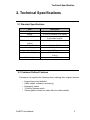
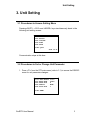
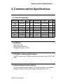
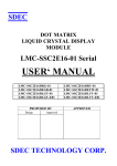
ProfiRT3
User’s Manual
Dynaservo Inc.
email: [email protected]
http://www.dynaservo.com
The information in this document is subject to change without notice and should not be
construed as a commitment by Dynaservo Incorporation. Dynaservo Incorporation assumes no
responsibility for any errors that may appear in this document.
In no event shall Dynaservo Incorporation be liable for incidental or consequential damages
arising from use of this document or of the software and hardware described in this document.
This document and parts thereof must not be reproduced or copied without Dynaservo
Incorporation´s written permission, and contents thereof must not be imparted to a third party
nor be used for any unauthorized purpose. Contravention will be prosecuted.
Additional copies of this document may be obtained from Dynaservo Incorporation.
© Dynaservo Inc.
3950 14th Avenue, Suite 402
Markham, Ontario, Canada
L3R 0A9
Table of Content
1. Overview
1
2. Technical Specifications
2
2
2.1 Standard Specifications
2.2 Customer Defined Features
2
3. Unit Setting
3
3.1 Procedures to Access Setting Menu
3
3
3.2 Procedures to Set or Change Unit Parameter
3.3 Procedures to Set or Change LCD Backlight Setting or Key
Break Code
4
4. Communication Specifications
5
5
4.1 Cable Pin Definition
4.2 GSD File
5
4.3 ProfiBus Communication Speed
5
4.4 Node (Station) Number Setting
5
4.5 ProfiBus Terminator Switch
6
6
4.6 Communication Protocol
4.7 VC++ Sample Program for ProfiBus Master to Receive Data
from Slave
7
5. Keys, LED Locations & Key Code
8
6. Terminal Display
9
9
6.1 General Information
6.2 Error Message
9
6.3 Escape Sequence
10
Appendix: LCD Character Code
11
ProfiRT3 User Manual
Overview
1. Overview
The ProfiRT3 is a handheld control terminal with ProfiBus-DP communication
capability. The terminal is specifically designed for control of robotic systems and
automated machines. The ProfiRT3 integrates LCD display, keypad and operator
safety devices into one compact and convenient unit. Almost all features of the
ProfiRT3 can be customer defined to produce a truly dedicated control terminal for
any motion control applications.
ProfiRT3 User Manual
Technical Specification
2. Technical Specifications
2.1 Standard Specifications
Item
Keypad
Display
Emergency Stop Switch
Description
(5×8+4) mechanical key switches
15 row×20 character LCD display
Mushroom style, push-lock type switch,
2 dry contact outputs
3-Position Liveman Switch
2 dry contact outputs
(option)
Communication Interface
ProfiBus DP-V0
Power Supply
DC24V, 60mA
Working Temperature
0 ~ 40 Degree
Dimension Weight
235×120×30 (mm)
310 (g)
Cable Length
2m standard
2.2 Customer Defined Features
Customers can specify the following when ordering their original terminal:
•
•
•
•
•
Keypad layout and definition
Cable (length, connector, and wiring)
Emergency switch
3-Position liveman switch
Others (please contact our sales office for further details)
ProfiRT3 User Manual
Unit Setting
3. Unit Setting
3.1 Procedures to Access Setting Menu
Pressing<SHIFT>, <CLR> and <MODE> keys simultaneously leads to the
following unit setting screen:
===== RT3 Ver. 1.10 =====
<F1> RS232C
<F2> LCD/KEY
<F3> FONT
<F4> SAVE
<CLR> QUIT
2004.10.21
Communication stops at this time.
3.2 Procedures to Set or Change Unit Parameter
1. Press <F1> from the RT3 main menu (refer to 3.1) to access the RS232C
menu for unit parameter changes:
===== RT3 RS232C
<F1> BAUD RATE
<F2> DATA BITS
<F3> PARITY
<F4> STOP BITS
=====
09600
8
NONE
1
<CLR> MENU
ProfiRT3 User Manual
Unit Setting
2. Press <F1>-<F4> key to select the parameters and set corresponding
values.
No.
1
Parameter Name & Set Value
BAUD RATE = 9600
2
3
4
5
DATA BITS = 8
PARITY = NONE
STOP BITS = 1
KEY BREAK = CODE
Available Choices
300 / 600 / 1200 / 2400 / 4800
/ 9600 / 19200 / 56000
08/07
NONE/EVEN/ODD
1/2
NONE/ZERO/CODE
Note: Bold Face Indicates Default Values
!
For ProfiBus communication, the baud rate has to be set as 19200.
This is the unit internal communication speed, NOT the ProfiBus
communication speed between nodes, which can be as high as 12Mbps.
After parameters are changed, press <CLR> to return to the RT3 main
menu. Press <F4> to save the parameters.
If communication parameters are changed, please turn the power off and
then on in order for the new parameters to take effect.
3.3 Procedures to Set or Change LCD Backlight Setting or
Key Break Code
1. Press <F2> from the RT3 main menu (refer to 3.1)to access LCD/KEY
setting menu to set LCD Backlight setting or key break code.
===== RT3
LCD/KEY =====
<F1> BACKLIGHT ON
<F2> KEYBREAK
CODE
<CLR> MENU
2. Press <F1> to select from ON/60min/10min for screen backlight. “ON”
indicates the backlight will be turned on all the time. “10min/60min” indicates
the backlight will be turned off if none of the keys are touched for a time
period of 10/60 minutes.
3. Press <F2> to set the key break code among “CODE/NONE/ZERO”.
ProfiRT3 User Manual
Communication Specifications
4. Communication Specifications
4.1 Cable Pin Definition
Signal Name
Color
Signal
Level
I/O
Signal Name
Color
POW
(+24VDC)
Yellow(Red)
24V
IN
POW GND
Yellow(Black)
EMG1
Pink(red)
DRY
OUT
ENG1 COM
Pink(Black)
DRY OUT
EMG2
Grey(Red)
DRY
OUT
EMG 2 COM
Grey(Black)
DRY OUT
DeadMan1
Orange(Red2) DRY
Signal
I/O
Level
-
OUT DeadMan1 COM Orange(Black2) DRY OUT
DeadMan2
Grey(Red2)
DRY
OUT DeadMan2 COM Grey(Black2)
BD+
Orange(Red)
IN/OUT
NOT USED
White(Red)
BD-
Orange(Black)
IN/OUT
VGND
White(Black)
-
FG
Shield
-
NOT USED
DRY OUT
4.2 GSD File
DNX_0001.GSD
GSD Version: Revision 2
ProfiBus DP Version: DP-V0
4.3 ProfiBus Communication Speed
ProfiRT3 supports up to 12Mbps communication speed (refer to DNX_0001.
GSD).
4.4 Node (Station) Number Setting
The node (station) number is fixed at 16 for the time being. It is possible to
change the station number offline using a rotary switch in future.
ProfiRT3 User Manual
Communication Specifications
4.5 ProfiBus Terminator Switch
There is a jumper switch inside the unit to enable/disable the ProfiBus
terminator resistor. The switch name is S3.
Configuration
Function
[S3-1, S3-2]=[ON,ON]
Terminator ON
[S3-1, S3-2]=[ON,OFF]
Not Allowed
[S3-1, S3-2]=[OFF,ON]
Not Allowed
[S3-1, S3-2]=[OFF,OFF]
Terminator OFF
4.6 Communication Protocol
First Byte
Second Byte
Sending/Receiving Flag
7
6
5
4
3
2
1
Max of 20 bytes data
1 byte (Data Length)
Req
Busy
PROFIBUS
Sending
Data
Sending
{
Req ON
Req ON
ON
Busy ON
**
Busy ON
**
Busy OFF
**
Data
Data
}
PROFIBUS
Receiving
Data
Receiving
Sending
Receiving
Req ON
Busy OFF
OFF
Busy ON
Busy ON
ON
Input Data
Busy OFF
OFF
No
Yes
Busy ON
OFF
Req ON
ON
OFF
Req ON
ON
Req OFF
Output Data
END
END
ProfiRT3 User Manual
Communication Specifications
4.7 VC++ Sample Program for ProfiBus Master to Receive Data
from Slave
#define MASTER_REQUEST_BIT
#define MASTER_BUSY_BIT
#define SLAVE_REQUEST_BIT
#define SLAVE_BUSY_BIT
#define RESPONSE_TIMEOUT
0x01
0x02
0x01
0x02
3000
// msec
DWORD WINAPI WorkerThread( PVOID pContext )
{
UINT8 bTemp[3];
UINT8 bData;
DWORD dwStart;
CProfibusMaster1Dlg* pstrStatus = (CProfibusMaster1Dlg *)pContext;
CString strTemp;
while( fWorking )
{
if ( (pstrStatus->m_bOpenFlag == TRUE) && (bOnWrite == FALSE) )
{
bOnRead = TRUE;
ABS_ReadOutArea( pstrStatus->m_pPath, 0, bTemp, 3, 100 );
if ( bTemp[0] & SLAVE_REQUEST_BIT )
{
// Slave-Req ON
bData = bTemp[2];
bTemp[0] = MASTER_BUSY_BIT;
bTemp[1] = 0;
bTemp[2] = 0;
// Slave-Data
// Master-Busy ON
ABS_WriteInArea( pstrStatus->m_pPath, 0, bTemp, 3, 100 );
dwStart = GetTickCount();
while(TRUE)
{
if ( ABS_ReadOutArea( pstrStatus->m_pPath, 0, bTemp, 3, 100 )
!= TP_ERR_NONE)
break;
if ( !(bTemp[0] & SLAVE_REQUEST_BIT) )
break;
// Slave-Req
if ( GetTickCount() - dwStart >= RESPONSE_TIMEOUT )
break;
}
bTemp[0] = 0x00;
bTemp[1] = 0x00;
bTemp[2] = 0x00;
// Master-Busy OFF
ABS_WriteInArea( pstrStatus->m_pPath, 0, bTemp, 3, 100 );
pstrStatus->UpdateButtonStatus( bData );
}
bOnRead = FALSE;
}
Sleep(50);
}
return 0;
}
For details, please refer to the enclosed VC++ project file CD-ROM.
ProfiRT3 User Manual
Keys, LED Locations & Key Code
5. Keys, LED Locations & Key Code
The Keys and LED location of ProfiRT3 are shown below for 1-axis type and multiaxis type. The key code of ProfiRT3 is shown at the bottom right of each key. LCD
can display ASCII characters for 15 x 20 resolution.
The hexadecimal values shown in bold face at the bottom right corner of each key
represent the code to be sent out when the key is pressed. For example, if <F1>
is pressed, ProfiRT3 will send out “01” (hexadecimal). When <F1> is released,
ProfiRT3 sends out “80 + 01” (hexadecimal) by default.
!
The code that each key represented are NOT the standard ASCII
codes.
ProfiRT3 User Manual
Terminal Display
6. Terminal Display
6.1 General Information
ProfiRT3 displays, on its LCD, the received ASCII character at the current
cursor position. Every time it receives a character, the cursor moves from left
to right.
When the cursor reaches the furthest right-hand point, the cursor moves to
the left-hand side of next row.
When the cursor reaches the right-hand side of the last row, it moves to the
left-hand side of the first row.
For the corresponding characters and their ASCII codes, please refer to the
Appendix.
6.2 Error Message
Error Code
Displayed Error
00h(RT1)1
Connection Hand-Shake Code (ProfiRT3 sends 00h out)
08h(BS)
Back Space Code
0Ah(LF)
Line Feed Code (Cursor moves to next row. When it
reaches the last row, cursor will not move)
0Dh(CR)
Cartridge Return Code (Cursor moves to the beginning in
the same row)
1Bh(ESC)
Escape Code
Connection Test: send 00h to ProfiRT3. If 00h is received, then ProfiRT3 is
connected.
1
ProfiRT3 User Manual
Terminal Display
6.3 Escape Sequence
The escape sequence, represented by the Escape Code (1Bh) + one
character, has the following special meaning.
Escape Sequence Function
Specification
ESC A
Cursor UP
Cursor moves 1 row up
ESC B
Cursor Down
Cursor moves 1 row down
ESC C
Cursor Right
Cursor moves 1 character right
ESC D
Cursor Left
Cursor moves 1 character left
ESC E
Clear Display & Home Cursor
Clear display and cursor moves to the home position
ESC F
Cursor On
ESC G
Cursor Off
ESC H
Cursor Home
ESC J
Erase To End Of Screen
Erase from cursor position to the end of screen
ESC K
Erase To End Of Line
Erase from cursor position to the end of line
ESC L
Long Bell
ESC M
Erase Line
ESC N
Key Brake Code
When key is pressed generate the key code. When key is
released generate ‘key code’+’80h’
ESC O
Key Brake None
When key is pressed generate the key code. When key is
released do nothing
ESC P
Key Brake Zero
When key is pressed generate the key code. When key is
released generate `00h` code
ESC R
Enable Cursor Blink
ESC S
Disable Cursor Blink
ESC T
Short Tone
Active buzzer with short tone
ESC U
Enable Key Click
Beep when key is clicked
ESC V
Disable Key Click
Disable beep when key is clicked
ESC Y Pr Pc
Position Cursor At Pr, Pc
Cursor moves to row Pr and column Pc
ESC Z
Report Device ID
ESC [0a
LED0 ON
ESC [1a
LED1 ON
ESC [2a
LED2 ON
ESC [3a
LED3 ON
ESC [4a
LED4 ON
ESC [5a
LED5 ON
ESC [0b
LED0 OFF
ESC [1b
LED1 OFF
ESC [2b
LED2 OFF
ESC [3b
LED3 OFF
ESC [4b
LED4 OFF
ESC [5b
LED5 OFF
Row1, Col1=(20h+row position), (20h+column position)
ProfiRT3 User Manual
Send ProfiRT3 identification code(‘RT3 V1.10’)
10
Appendix
Appendix: LCD Character Code
The correspondence between characters and their ASCII codes is given below.
upper 4bits
lower 4bits
xxxx0000
0
1
10
RT1
11
100
101
110
111
0
@
P
`
p
xxxx0001
!
1
A
Q
a
q
xxxx0010
“
2
B
R
b
r
xxxx0011
#
3
C
S
c
s
xxxx0100
$
4
D
T
d
t
xxxx0101
%
5
E
U
e
u
xxxx0110
&
6
F
V
f
v
xxxx0111
‘
7
G
W
g
w
(
8
H
X
h
x
)
9
I
Y
i
y
*
:
J
Z
j
z
+
;
K
[
k
{
,
<
L
\
l
|
-
=
M
]
m
}
xxxx1110
.
>
N
^
n
xxxx1111
/
?
O
_
o
xxxx1000
BS
xxxx1001
xxxx1010
LF
xxxx1011
ESC
xxxx1100
xxxx1101
ProfiRT3 User Manual
CR
11