1
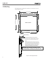
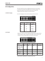
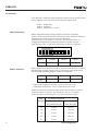
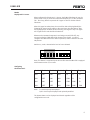
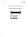
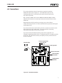
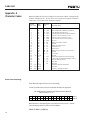
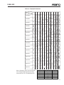
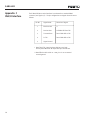
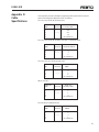
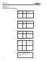
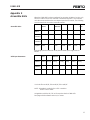
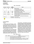
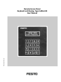
E.ABG-LED TN 18445 (Rev.11) Remote Access Panel Keyboard and Display, Type E.ABG-LED User Manual E.ABG-LED Type: Description: E.ABG-LED 8345 Remote Access Panel Publication No.: TN 18445 (Rev 11) Edition: January 1999 Author: Robert Conde Festo Corporation 395 Moreland Road Hauppauge, New York U.S.A. 11788 Telephone: (516) 435-0800 Copyright 1989-1999 by Festo Corporation. This document, in whole or portions thereof, may not be copied, duplicated, or transferred by any means whatsoever without the prior written permission of Festo Corporation. The information contained in this document is subject to change without notice. E.ABG-LED Table of Contents 1.0 Introduction ...................................................................... 1 2.0 Mounting .......................................................................... 2 3.0 Configuration .................................................................... 3 3.1 Language Selection ............................................. 3 3.2 Controller Model Selection .................................. 3 3.3 Personality ......................................................... 4 3.4 Self Test ............................................................. 6 4.0 Connections ..................................................................... 7 5.0 Operation ......................................................................... 8 Appendix A Character Codes and Commands ........... 10 Appendix B Self Test Mode ....................................... 12 Appendix C RS 232 Interface ..................................... 14 Appendix D Cable Specifications ............................... 15 Appendix E Accessible Units ..................................... 17 Appendix F Internal Text Messages .......................... 18 Appendix G Installing the E.ABG-MEM ...................... 19 E.ABG-LED E.ABG-LED 1.0 Introduction The Festo E.ABG-LED (Remote Access Panel) is designed for use with Festo PLC models FPC 101, 102, 103, 202I, 202C, 404, 405 as well as Festo IPC and FEC Controllers. Typical Applications - Display of User Oriented Text Messages - Input of Operating Parameters - Direct access to the PLC Command Interpreter (C.I.) - Modification of Timers, Counters and Registers - Displaying / Clearing the FPC System Status Standard Features - Integrated 2 lines by 16 characters; negative, transmissive LCD display with LED backlighting - Selectable national language (English, German, French, Spanish) - Serial Interface, with both 20mA and RS 232 (V24) connections - Able to store 100 internal user text messages in RAM / EPROM / NOVARAM / EEPROM memory - Intelligent microprocessor design for ease of use - Operating voltage 24Vdc... no special power required - Flexible configuration options allow the unit to function as: - a display-only device - an interactive terminal - an intelligent access panel to interact with the FPC C.I. as well as a display, including selectable levels of access - Robust mechanical design allows mounting in harsh environments Optional Features - PC based editor for creation of internal (canned) messages, loading of messages to display, and production of Eprom files - Plug-in PC board for RAM-based development of internal user text messages Specifications - Power required: 24 Vdc @ 120 mA (typical) - Storage temperature: -20 - +70oC - Operating temperature: 0 - 55oC - Relative humidity: 0 - 95% (non-condensing) - Display: 2 lines of 16 characters US ASCII and foreign character sets 8K - Internal programmable text storage Ordering Information Part Number: Type: 8345 E.ABG-LED 1 E.ABG-LED 2.0 Mounting The E.ABG-LED panel is designed for installation in a front panel cut out of a control cabinet or console. 5.0" [127mm] PANEL CUTOUT 4.5" [114.3mm] 5.0" [127mm] 4.15" [105.4mm] 4.65"[118.1mm] .177" [4.5mm] diameter 4.5" [114.3mm] 1.38" [35 mm] approximately Allow approximately 2.5"[63.5 mm] for clearance when installing a DB9 connector, housing, and/ or optional memory board. Note: When equipped with a metal enclosure, the enclosure must be removed during mounting. After the keypad is mounted to the control cabinet, the metal enclosure can be secured using the (4) mounting screws provided. CAUTION: Use care when mounting to avoid pinching,folding,or creasing the keyboard cable. Figure 2/1 Mounting Dimensions 2 E.ABG-LED 3.0 Configuration This section details the various configuration options that can be selected to customize the operation of the E.ABG-LED for a particular operation. All options except selection of the interface type (20 mA vs. RS232) are configured by properly setting the 10-position dipswitch. 3.1 National Language One of four languages can be selected by setting switches 9 and 10. ON 1 2 3 4 5 6 7 8 9 10 Switch 9 Switch 10 Language OFF OFF English OFF ON German ON OFF French ON ON Spanish 3.2 FPC Model Switches 6, 7 and 8 are used to configure the E.ABG-LED according to the FPC model you will be using. In addition to selecting the controller model, these settings also select the appropriate serial interface characteristics. ON 1 2 3 4 5 6 7 8 9 10 Model Switch 6 Switch 7 Switch 8 Parameters FPC 101, 102, 103B/AF, 202C, SB/SF202, SF3, IPC, FEC ON ON ON 9600,N,8,1 FPC 202I OFF ON ON 4800,N,8,1 FPC 202C, SB/SF 202 ON OFF ON 9600,N,8,1 FPC 404 OFF OFF ON 4800,N,8,1 Note: All other combinations are reserved for future use. 3 E.ABG-LED 3.3 Personality The E.ABG-LED is capable of being configured to operate in one (1) of three basic modes. Switches 2,3,4 and 5 are used to select the required mode. Mode 1 - Display Only Mode 2 - Interactive Mode 3 - Display and C.I. Access Mode 1 Display Only: When configured for Display Only operation, the keypad is completely Inactive. Text received from the FPC will be shown on the display. In addition to displaying text, several special codes (see appendix A) for functions such as "clear display," "clear line," etc. will be processed. To configure the E.ABG-LED for Display Only operation, switches 3,4 and 5 must all be set to OFF. In this mode, the position of switch 2 is irrelevant. ON 1 2 Switch 2 X Mode 2 Interactive: 3 4 5 6 7 8 9 10 Switch 3 Switch 4 Switch 5 OFF OFF OFF When configured for Interactive operation, any text received from the controller will be displayed and the keypad is active. Typical uses of this mode include interacting with FPC BASIC programs as well as Text Modules. Switch 2 OFF Switch 3 Switch 4 * * Switch 5 * * In this mode of operation, switches 3, 4 and 5 can be set to any combination except that 3, 4 and 5 cannot ALL be set to OFF! Further, in this mode, pressing any of the numeric keys (0-9) will transmit the respective number to the FPC. The non-numeric keys (T, C, R, Status) assume the role of Function keys F1, F2, F3 and F4 and will transmit: Key Pressed 4 Text String Transmitted 101, 102, 103, 202C FEC, SB/SF 202, IPC 202I / 404 / 405 F1 A <cr> K1 <cr> F2 B <cr> K2 <cr> F3 C <cr> K3 <cr> F4 D <cr> K4 <cr> CI X <cr> X <cr> <cr>= carriage return E.ABG-LED Mode 3 Display and C.I. Access: When configured for Display and C.I. Access, the E.ABG-LED allows the user, by means of the CI key, to access the Command Interpreter (C.I.) of the connected FPC. The CI key, when first pressed will 'Logon' to the FPC and the LED will illuminate. After this Logon has taken place, the user will be able to Display/Modify the following FPC internal units subject to the restrictions described below. After having displayed or modified the desired units, pressing the CI key once again will 'Logoff' the FPC and the LED will switch off. Whenever the Command Interpreter is not being accessed (LED OFF), any text received by the E.ABG-LED will be shown on the display. In order to configure the E.ABG-LED for this mode of operation, switch 2 must be set to the ON position. Switches 3, 4 and 5 determine the level of access allowed. ON 1 2 3 4 5 6 7 8 9 10 Note: This feature is supported by the IPC and FEC when the ABG-LED is equipped with firmware version 3.3 or newer. Configuring the Access Level: Switch 2 Switch 3 Switch 4 Switch 5 ON ON ON ON D D D ON OFF ON ON D/M D D ON ON OFF ON D/M D/M D ON OFF OFF ON D/M D/M D/M Note: Timer Counter Register D = Unit may only be displayed D/M = Unit may be displayed and optionally modified The System Status can be displayed and cleared regardless of the configured Access Level. 5 E.ABG-LED 3.4 Self Test The E.ABG-LED contains extensive self test routines which may be accessed by properly setting switch 1. When switch 1 is set to the ON position, a short self test is performed each time the unit is switched on. If more extensive testing is required, switch 1 can be set to the OFF position. When power is applied and switch 1 is set to the OFF position, the extensive self test routines are executed. Appendix B contains details regarding these routines. ON 1 2 Switch 1 6 3 4 5 6 7 Operation ON Normal Operation OFF Extensive self tests 8 9 10 E.ABG-LED 4.0 Connections This section details the electrical connections required to install the E.ABG-LED. Please refer to figure 4/1. The E.ABG-LED requires 24 Vdc operating power which is connected to the terminal strip located at the top of the circuit board. Note: DO NOT CONNECT PE TO THE COMMON OR NEUTRAL WIRE OF AN AC CIRCUIT! The PE terminal is electrically connected to the metal chassis of the E.ABG-LED. Depending upon the FPC model you are using, you can select either a 20 mA current loop interface or a RS232 (V24) interface by properly installing the small jumper block. If you have selected the 20 mA interface, then the connection to the FPC can be made using Festo cable number 8325. The 20 mA selection is normally used when connecting to an FPC 202 or FPC 404. If you have selected the RS232 interface, please refer to appendix C for information regarding required cables. The RS232 interface is normally used with the FPC 101, FPC 404 slide-in memory card (8262), FPC 405, and the Festo IPC and FEC controllers. Power connections 24 Vdc 0V PE (protective earth ground) PE 0V 24V RS232 20 mA RS-232 (V24) 20 mA RS-232 (V24) connector Festo E.ABG 7-89..REV PN 8k 32k C.I. EPROM 20 mA RS232 20 mA connector Configuration switches (Shown with metal enclosure removed) Figure 4/1 Connection Locations 7 E.ABG-LED 5.0 Operation Using Mode 3 When the E.ABG-LED has been configured for mode 3, the user is able to access the Command Interpreter. The following provides details of operation. NOTE: This mode is not currently supported for the IPC controller Accessing the C.I.: When first powered up, the E.ABG-LED will display the message: CI for LOGON If the CI key is pressed, the E.ABG-LED will attempt to access the Command Interpreter. If this process is not successful, the message LOGON FAILURE Check Cables will appear. Check to see that the E.ABG-LED is properly configured, the cables are connected and the FPC is operational. Pressing the CI key again will re-try the LOGON operation. If the LOGON is successful, the FPC C.I. message (e.g. FPC 404 V2.12 >) will be displayed and the LED will illuminate. Subject to the restrictions configured (see section 3.3), the user may now perform the following operations: System Status: Press the Status Key. The current System status will be displayed. The user may either: Press the 0 key to clear any error, or press the Enter Key which will leave the system status unaltered. Timer / Counter / Register: To Display and optionally modify a Timer or Counter Preselect or Register, the user need only press the T, C, or R key followed by the desired number and the Enter Key. For example, to access timer 6, the entry would be: T6<Enter Key> The current value of the Timer Preselect would be displayed. For example: T6=1234 8 E.ABG-LED If the configured access level only allows displaying timer preselects, no operator input is allowed. However, if the configured access level does allow modifying timer preselects, then the E.ABG-LED would display: T6=1234:_ The user then may simply press the Enter Key to keep the existing value, or enter a new value: T6=1234: 705 followed by the Enter Key. If the user attempts to access a non-existing unit (e.g. Time 339), or attempts to modify a value and enters a value outside of the predefined range (see Appendix E); the message Invalid Entry will be displayed. When all required entries have been completed, the CI key should be pressed, which will terminate the connection to the Command Interpreter and switch-off the LED. When the C.I. is exited, the message: Logged Off will appear. It is important that after completing required entries, that the C.I. is exited since when the C.I. is active it will slow down the normal processing of programs. Communication Errors: If, while accessing the C.I., a command cannot be completed (e.g. cable connection broken, FPC lost power etc.) the message: CI Halt will appear. The E.ABG-LED will then perform a reset sequence, after which the message: CI for LOGON will again be displayed. This process allows for recovery from communication errors without requiring the complete control system to be shut down. 9 E.ABG-LED Appendix A Character Codes When the E.ABG-LED has been configured for operation in Mode 1 (Display Only) or Mode 3 (Display and C.I. Access) and is not currently accessing the Command Interpreter, received text will be handled as follows: Decimal Code Code HEX ASCII Character/ Code 0 1 2 3 4 5 6 7 8 9 10 11 12 13 14 15 16 27 28 29 30 31 32 128 160 00 01 02 03 04 05 06 07 08 09 0A 0B 0C 0D 0E 0F 10-1A 1B 1C 1D 1E 1F 20-7F 80-9F A0-FF ^@ ^A ^B ^C ^D ^E ^F ^G ^H ^I ^J ^K ^L ^M ^N ^O Null SOH STX ETX EOT ENQ ACK BELL BS HT LF VT FF CR SO SI ^[ ^\ ^] ^^ ^_ ESC FS GS RS US - 26 - 127 - 159 - 255 Resulting Action Ignored Reset E.ABG-LED to Power-Up Condition Clear Display & Home Cursor Clear Display & Display Firmware Revision Position Cursor to column 1, Line 1 Position Cursor to column 1, Line 2 Clear Current Line, Cursor to column 1 Ignored Move Cursor Left 1 position Ignored Move Cursor down 1 line Normal Cursor Block Cursor Move Cursor to column 1 of current line Ignored Cursor Off Ignored Lead In Character for Cursor Positioning Lead In Char. for Display Backlight Control Display internal text nnn Reserved Reserved Standard Character Displayed Reserved Graphics / Foreign Characters Please refer to Table A/1 which presents the full displayable character set. Direct Cursor Positioning: The E.ABG-LED supports direct cursor positioning. In order to position the cursor to an absolute location, the sequence: ESC CHR$(position) should be transmitted to the E.ABG-LED, where position = 1-32. 1 2 3 4 5 6 7 8 9 10 11 12 13 14 15 16 17 18 19 20 21 22 23 24 25 26 27 28 29 30 31 32 Line 1 Line 2 With reference to the above figure, to position the cursor to line 2, column 4 the following sequence can be sent in FPC BASIC: PRINT CHR$(27), CHR$(20), 10 E.ABG-LED Table A/1 - Displayable Characters High Order Low 4 bit 0010 0011 0100 0101 0110 0111 1010 1011 1100 1101 1110 1111 Order 4 bit xxxx0000 xxxx0001 xxxx0010 xxxx0011 xxxx0100 xxxx0101 xxxx0110 xxxx0111 xxxx1000 xxxx1001 xxxx1010 xxxx1011 xxxx1100 xxxx1101 xxxx1110 xxxx1111 Note: Characters codes (177-181 decimal) have changed beginning with operating system version 3.1e. The differences are: Version 177 178 179 180 181 < 3.1e =>3.1e å Å Ä Ö Ü 11 E.ABG-LED Appendix B Self Test Mode Switch 1 allows the E.ABG-LED to be configured for either Normal operation or to enter a diagnostic self test mode. (see section 3.4) The Self Test mode (Switch 1= OFF), allows complete diagnostic testing of the E.ABG-LED. While not normally used, it can be quite helpful in determining whether any problems are being caused by the E.ABG-LED or the connected device. When power is applied, the message: Self Test Version X . Y will appear. The Version number corresponds to the E.ABG-LED internal software that is contained in Eprom. During this time, the LED will blink ON/OFF several times. Next, the message: Self Test Config=nnnnnnnn will appear, where nnnnnnnn equates to the current settings of switches 8-1. This allows you to confirm that the circuitry that accesses the configuration switch is functioning properly. Switches set to the OFF position will be displayed as 1, while switches set to the ON position will be displayed as 0. The next message to appear will indicate the FPC model for which the E.ABG-LED is currently configured. For example: Self Test Model= FPC 404 The next message will display the current communication configuration: Self Test BAUD= nnnn,N,8,1 Where nnnn equates to the Baud rate. The standard protocol also uses No parity, 8 data bits and 1 stop bit. 12 E.ABG-LED A test of the E.ABG-LED processor memory is now performed and the message: MEMORY TEST WAIT is displayed. If the memory test passes, the message: MEMORY TEST WAIT Memory Test OK will be displayed. The keyboard is now tested to be certain that no keys are stuck in a closed position. The message: Keyboard in Test appears. If any of the 16 keys is faulty, the message Keyboard FAILURE will appear. If no such failure is found, the message Keyboard Test OK will be displayed. If the test has been successful, the message: Select KEY: will be displayed. Each key as it is pressed, will be displayed. Pressing the CI key will exit the keyboard test and the message: LOOP BACK will be displayed. In this mode, you may connect a "loop back connector" to the serial port (e.g. connect DB9 pins 2 &3 together). Each key pressed will be transmitted out the serial port, through the "loop back connector" and be displayed on the display screen. This test confirms proper operation of the serial communication circuits. The self test will remain in this mode until the power is switched off and switch1 has been set to the normal operation position (ON). 13 E.ABG-LED Appendix C RS232 Interface The E.ABG-LED RS232 serial interface is terminated in a standard DB9S connector (see Figure 4/1). The pin configuration and signal directions are as follows: Pin No. Signal Name Direction of Signal 1 Earth Ground ** 2 Receive Data to E.ABG-LED from FPC 3 Transmit Data from E.ABG-LED to FPC 4 D.T.R * from E.ABG-LED to FPC 5 Signal Ground * Note The D.T.R. signal is always held at a true logic level by the E.ABG-LED. All unspecified pins are unused. ** Note Effective with serial no. 7100, pin 1 is not connected to earth ground. 14 E.ABG-LED Appendix D Cable Specifications This appendix provides information regarding cable specifications required when connecting the E.ABG-LED to FPC controllers. FPC 101, 102, 103 B/AF (Primary Port): E.ABG-LED DB9P 2 3 5 4 Direction <-----> FPC 101 271290 (cable) C10 C11 C9 no connection FPC 101, 102, 103 B/AF (Primary Port with I/O Expander Bus) E.ABG-LED DB9P 2 3 5 4 FPC 101, 102, 103 Direction I/O Expander DB25P <-----> 3 2 7 no connection FPC 101, 102, 103 AF (Secondary Port): E.ABG-LED DB9 2 3 5 4 Direction <-----> FPC 101, 102, 103 AF DB9P 3 2 5 no connection SB/SF 202/SF3 E.ABG-LED DB9P 2 3 5 4 Direction <-----> SB/SF 202 150288 (cable) 2 1 3 no connection FPC 404 Slide-in Module 8262: E.ABG-LED DB9P 2 3 5 4 Direction <-----> 8262 DB25P 2 3 7 no connection 15 E.ABG-LED Appendix D RS-232 Cable Specifications FPC 405 Processor Diagnostic Port E.ABG-LED DB9P 2 3 5 4 Direction <-----> FPC 405 DB9P 3 2 5 no connection FPC 405 Communication Processor E.ABG-LED DB9P 2 3 5 4 Direction <-----> FPC 405 DB25P 2 3 7 no connection Festo IPC (HC12...17) Communication Port E.ABG-LED DB9P 2 3 5 4 Direction <-----> Festo IPC DB9S 3 2 5 no connection Festo FEC-20 Communication Port E.ABG-LED DB9P 3 2 4 5 Festo cable Direction 272382 (13000965) or Type E.FEC-KBG 2 <------> ----> ------ 2 1 3 4 Festo FC30 and IPC-HC0x Communication Port 1. Use Festo cable type E.FEC-KBG-5 or 2. Use Converter SM14 + cable 271331 (13000334) 16 E.ABG-LED Appendix E Accessible Units When the E.ABG-LED has been configured for operation in Mode 3 (section 3.3), the user is able to access the controller Command Interpreter. The controller units that are accessible to the user depend upon the FPC model. The following provides details for the various controller models. Unit FPC100 Series* FPC202I FPC202C, SF3 SB/SF202 FPC404 FPC405 IPC, FEC System Status yes yes yes yes yes yes yes Timer Preselect O-31 O-7 O-31 O-31 O-7 O-63 O-255 Counter Preselect O-15 O-7 O-31 O-31 O-15 O-63 O-255 Register O-63 no O-63 O-127 O-63 O-127 O-255 Accessible Units: Depending upon the controller model, the allowable input range varies as follows: Valid Input Parameters: Unit FPC100 Series* FPC404 FPC405 IPC, FEC Timer O-65535 O-32767 O-65535 Preselect [O.O1s] [O.O1s] [O.O1s] O-65535 O-65535 [O.O1s] [O.O1s] O-65535 [O.O1s] O-65535 [O.O1s] Counter O-65535 O-9999 Preselect O-65535 O-65535 O-65535 O-65535 O-65535 Register O-65535 O-65535 O-65535 O-65535 O-65535 O-63 FPC202I FPC202C, SF3 SB/SF202 none * Includes FPC 101 B/AF, FPC 102 B/AF, FPC 103 B/AF NOTE: Using Mode 3 with the IPC or FEC controllers version 2.20 or newer. Using Mode 3 with the IPC, FEC or SF3 requires that the E.ABG-LED be equipped with software version 3.3 or newer 17 E.ABG-LED Appendix F Internal Text Messages One of the most powerful features of the E.ABG-LED Remote Access Panel is the ability to internally store up to 100 user programmable text messages. This helps to conserve precious PLC memory for control program usage. User text messages are developed using a PC-based Text Display Editor available from Festo. Each text message may contain up to 63 text and/or control characters. Therefore, control sequences (see Appendix A) such as "clear display", direct cursor positioning, backlight control, etc., may be embedded within the messages. The E.ABG-LED provides several flexible alternatives for the development and storage of internal text messages. Optional E.ABG-MEM memory board: The optional E.ABG-MEM board can be easily installed (see Appendix G) and provides an ideal method for developing and testing text messages. Text messages can be rapidly loaded and tested using the standard 8K Ram memory supplied. The user may purchase and install an 8K EEPROM or 8K Novaram (8K Ram with built-in battery backup) which combines the convenience of standard Ram memory with longterm storage ability. Using the facilities of the Display Editor, you may produce an industry standard Intel hex file and store the text messages in an 8K Eprom which provides very high security against message loss. Placing user text messages within the E.ABG program memory: The E.ABG-LED also offers an alternative method for low-cost, high-security storage of text messages which is particularly suited to multiple unit or O.E.M. customers. This method allows the storage of text messages within the same 32K Eprom that contains the E.ABG-LED operating software. Using this method, it is not necessary to install the optional E.ABG-MEM board. Normally the text messages can be developed and tested using the E.ABG-MEM board although this is not necessary. Software Commands: By sending the proper software commands to the E.ABG-LED, an internally stored text message may be displayed. To display a text message, the user's program must transmit a 2-character sequence to the E.ABG-LED. The first character is always the control character FS (1d hex) followed by the ASCII character with a binary value corresponding to the desired message number. (Also refer to Appendix A.) For example, to display internal message number 65 the following 2-byte sequence is used: ctrl ] (GS) + A = 1d hex + 65 decimal Likewise to display message number 6 transmit: ctrl ] (GS) + ctrl F = 1d hex + 6 decimal FST program modules are available to assist the user in accessing messages from various programming languages. 18 E.ABG-LED Appendix G Installing the E.ABG-MEM CAUTION: This section details the installation of the E.ABG-MEM memory board on the E.ABGLED Remote Access Panel. Please note that the E.ABG-LED and E.ABG-MEM are furnished in static-controlled packaging. These units contain devices which can be damaged if not handled carefully. To avoid such damage: - Always store and ship these units using the static-free packaging provided. Never place the units in normal plastic bags or styrofoam packaging. - Always perform installations in static-free environments... avoid carpeted areas and static-producing clothing. - Always be certain that ALL power is switched off before removing or installing any component. Materials Provided: Step by Step Installation The E.ABG-MEM memory board Part Number 271328 (13000972) contains the following: (1) memory board with 8K Ram chip installed (1) mounting screw to secure the memory board (1) jumper installed on header JP1 (1) jumper installed on header WE (4) threaded spacers 1. Switch off ALL power. 2. Remove the (4) screws securing the rear sheet metal cover. 3. Referring to Figure 4/1 (page 7), carefully remove the CI Eprom from the main E.ABG-LED circuit board socket, by gently lifting each end by inserting a small screwdriver between the Eprom and the socket. Please note that the top end (toward terminal connections) of the Eprom has a small notch which designates the pin 1 end of the Eprom. The Eprom will be reinstalled in a later step. For reference, all of the ICs located on the main board are oriented with pin 1 facing the top of the board. 4. Refer to Figure G/1 and carefully install the E.ABG-MEM board by: a.) Align the 28-pin header on the underside of the E.ABG-MEM board with the socket from which you removed the Eprom in Step 3. Also note the single pin at location J2 (just below IC number U2) which must be aligned with the mating socket on the main board. b.) After having checked that ALL pins are properly aligned, gently press the E.ABG-MEM board until it is seated fully. c.) Secure the E.ABG-MEM board to the main board using the supplied 6-32 screw in conjunction with the factory-installed threaded nylon spacer located on the main board. 19 E.ABG-LED U1 JP1 WE Jumper On = 8K Ram Jumper Off = 8K Novaram 8K Eprom 8K EEprom WE ON = RAM/EEprom Loading enabled WE OFF = Memory protected U2 Figure G/1 5. Install the CI Eprom removed in Step 3 into the left hand (U1) socket of the E.ABG-MEM board. Be certain to orient the notched (pin 1) end of the Eprom towards the top of the board. First make sure that all 28 pins are aligned and then gently press the Eprom in place until seated. 6. If the E.ABG-MEM board is being permanently installed, then the four (4) supplied spacers should be installed to provide adequate clearance and support for the rear sheet metal cover. a.) Remove the four (4) 6-32 screws located at the corners of the main E.ABG-LED board. b.) Install a threaded spacer at each location to secure the main board. c.) The remaining four (4) screws can be used again when the rear sheet metal cover is installed. 20 E.ABG-LED Configuration: Header JP1: Header JP1 is supplied with a jumper installed. When installed, this jumper will allow the contents of the standard 8K Ram to be maintained for several minutes with the main power removed. This jumper should be removed if the standard 8K is replaced with either: an 8K Eprom an 8K Novaram an 8K EEPROM Caution: Failure to remove jumper JP1 when a Novaram is installed may result in the loss of stored messages. Additionally, always remove jumper JP1 while inserting or removing memory devices. Header WE: Header WE is supplied with a jumper installed. When installed, this permits loading of text messages. When the WE jumper is removed, the ABG memory is write-protected. Optional Memory Devices: As described in Appendix F, the standard 8K Ram memory (located on the E.ABGMEM board) may be replaced by: - 8K Eprom - 8K EEPROM Festo No. 271330 (13000340) 21 E.ABG-LED