1
E S/ Ser v er P C I G at ew ay
Twinax Emulation Card
Server and Client Emulation Software
User’s Administration Manual
Complete Midrange Solutions
Part Number: 62-402907301
Rev. C
Table of Contents
Legal Notices
5
CHAPTER 1
6
INTRODUCTION
ES/Server Features
ES/Server card Technical Specifications
6
7
8
CHAPTER 2
9
INSTALLATION
Preparations
Installing The ES/Server PCI Adapter
Connecting the T-cable and Twinax Cables
Installing the ES/Server Hardware Driver
Basic Instructions to Install the Hardware Driver
Windows XP Driver Installation Instructions
Verify the Driver
Windows 2000 Driver Installation Instructions
Verify The Driver
Windows 98 Driver Installation Instructions
Verify The Driver Installation
Windows NT Driver Installation Instructions
Installing The ES/Server Software
To Install the Emulation Software
Configuring ES/SERVER
9
9
10
11
12
12
13
13
14
19
23
23
24
25
25
28
CHAPTER 3
33
RUNNING THE EMULATION ON THE ES/SERVER
Running ES32
Starting a session
Status Indicators:
33
33
33
36
CHAPTER 4
37
ES/CLIENT INSTALLATION INSTRUCTIONS
Preparations
ES/Client Software Installation
37
37
38
CHAPTER 5
40
ES/CLIENT STARTUP INSTRUCTIONS
ES/Client Startup Instructions When Using a VPN link
40
41
CHAPTER 6
42
CONFIGURING ES32
Session Properties
42
42
2
ES/Server User’s Manual
General Settings
Display options
HotSpots
Font
API
Colors
Keyboard
Using Macros
To record a macro
To play back a macro
Adding a macro to the toolbar
To pause a macro
To edit a macro
The ES32 Printer
Adding and configuring an ES32 Printer
To Open A Printer Session
Print Data Control
Formatting that occurs on the host
AS400 Host Print Transform
Getting Help
44
45
45
48
49
50
51
54
54
54
55
56
56
57
57
58
59
59
60
62
APPENDIX A
63
TERMINAL DEVICE TYPE CODES
63
APPENDIX B
64
SYSTEM 36 PRINTER DEVICE TYPE CODES
5256 Printer
5224 and 5225 Printers
5219 / 3812 Printer
64
64
65
66
APPENDIX C
67
AS400 HOST PRINT TRANSFORM
67
APPENDIX D
69
TROUBLESHOOTING
Indicators
Cursor Positions:
Status Indicators:
69
69
69
69
PROBLEM GUIDE
ES/PCI Error Messages
Session Questions:
Screen Questions:
Font Questions:
Keyboard Questions:
Printer Troubleshooting
Other Questions:
ES/Server Section
70
70
77
78
78
79
81
83
84
ES/Server User’s Manual
3
ES/Server Card Installation & Configuration Problems
ES/Client Installation Problems
Network Problems
Other ES/Server-specific Problems
APPENDIX E
86
87
89
92
95
IBM 5250 ERROR CODES
0000 to 0038, Operator Entry Error Codes
0040 to 005F Communication Network Errors
0060 to 0069 Ideographic Errors
0070 to 0078, Text Entry Assist Error Codes
0097 to 0099 Host Support Error Codes
100000 to 101D00 X.25 Error Codes
95
96
98
99
99
100
100
APPENDIX F
102
GLOSSARY
102
APPENDIX G
104
TECHNICAL SUPPORT
104
APPENDIX H
105
ES/SERVER LIMITED WARRANTY
105
4
ES/Server User’s Manual
Legal Notices
COPYRIGHT
Copyright 2006 © Ringdale UK Ltd. All rights reserved. No part of this publication may be
reproduced, transmitted, transcribed, stored in a retrieval system, or translated into any language or
any computer language, in any form or by any third party, without prior permission of Ringdale UK
Limited.
DISCLAIMER
Ringdale UK Ltd. reserves the right to revise this publication and to make changes from
time to time to the contents hereof without obligation to notify any person or
organization of such revision or changes. Ringdale UK Ltd. has endeavored to ensure
that the information in this publication is correct, but will not accept liability for any error
or omission.
TRADEMARKS
All trademarks are hereby acknowledged.
Part Number: 62-402907301
Rev. C
Chapter 1
INTRODUCTION
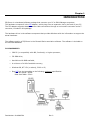
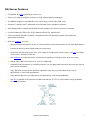
ES/Server is a hardware/software package that connects your PC to IBM Midrange computers.
The hardware component is the PCI adapter, which plugs into an expansion slot in the back of your PC.
The PCI adapter supports standard twinax cable connections through an on-board D-connector and a Tconnector, included in this package.
The hardware driver is the software component that provides Windows with the information to support the
actual hardware.
The software portion of ES/Server is the Emerald Series emulation software. The software is included on
the enclosed diskettes.
PC REQUIREMENTS
•
IBM PC (or compatible) with 486, Pentium®, or higher processor,
•
CD-ROM drive,
•
Hard drive with 6MB available,
•
A minimum of 4 MB of available memory,
•
Windows 98, NT 3.51 (or above), 2000 or XP,
•
One PCI free slot according to the following minimum specification:
Data Bus speed: 33MHz
−
Data Path Width: 32 bit
−
Part Number: 62-402907301
Rev. C
ES/Server Features
•
Compatible with PCI specification version 2.1.
•
There is no need to configure memory and I/O address during installation.
•
The adapter supports, automatically, the entire range of interrupts (IRQ 3-15).
•
Supports 7 sessions and 7 addresses using Emerald Series emulation software.
•
Nine display station models and thirteen printer models from which to choose to emulate.
•
Communicates with IBM S/36, S/38, Advanced Series 36, and AS/400.
•
32-bit Emulation Software included. Setup detects the PC operating system and installs the
appropriate emulation.
•
With the emulator, you can:
o
Open multiple host sessions at any one time and work with those sessions to run host applications;
o
Emulate a variety of host display stations and printers;
o
Customize the IBM host screen to fit your needs by changing the screen colors, the font, the shape
of the cursor, and other features;
o
Use HotSpots to enact host menu items and commands by clicking on them with the mouse;
o
Assign many IBM host functions to your PC’s keyboard;
o
Automate host procedures by recording macros. You can play back the macro any time you want to
perform the procedure;
o
Copy IBM host screens to the Windows clipboard. From there you can paste them into PC
applications or other host applications;
o
Copy tabular data from the IBM host to PC applications, such as spreadsheets;
o
Use ETU to transfer files between the IBM host and the PC. ETU is a file transfer utility, available
from NLynx Systems.
ES/Server User’s Manual
7
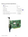
ES/Server card Technical Specifications
•
PCI version . . . . . . . . . . . . . . . . . . . . . . . . . . . . . . . . . 2.1
•
Power Requirements . . . . . . . . . . . . . . . . . . . . . . . . . .. +5, +12 volts
•
Emulation . . . . . . . . . . . . . . . . . . . . . . . . . . . . . . . . .. 5250
•
Signal Strength . . . . . . . . . . . . . . . . . . . . . . . . . . . . . . . 5000 feet (Twinax)
•
Signal Strength . . . . . . . . . . . . . . . . . . . . . . . . . . . .. . 15 – 500 feet (CAT5 & baluns)
•
IRQ and Memory . . . . . . . . . . . . . . . . . . . . . . . . . . . .. Auto (Plug and Play)
•
ES/Server card part number . . . . . . . . . . . . . . . . . . . . .. . 00-31-9607-000
•
ES/Server cable assembly, T-connector, twinax-DB15M . . .. 07-351908501
•
ES/Server emulation software . . . . . . . . . . . . . . . . . . . . .. . 63-373680901
Part Number: 62-402907301
Rev. C
Chapter 2
INSTALLATION
Preparations
If neither ES32 nor the Twinax Adapter was previously installed, you can start at the next section.
Otherwise, we recommend removing all previous versions of ES95 (or ES32) from the computer, by
using the uninstall utility found in the ES95 (or ES32) folder and deleting the physical driver files from the
PC. This will prevent Windows from reinserting an incorrect hardware driver.
1)
Click the Windows Start button.
2)
Select “Programs”, then the ES32 (or ES95), and then finally “Uninstall”.
3)
You should also uninstall the hardware from the Device Manager. (If the Twinax Adapter hardware
was been done before, and the driver chosen was wrong, then you must uninstall.
4)
Go to the Desktop, and right-click on "My Computer".
5)
Select "Properties", which will bring up the System Properties window.
6)
Select the “Hardware” tab, and then select the Device Manager button.
7)
First look for “Twinax Adapters”, if it does not exist, then look for ‘PCI Simple communication
device’, or a card that you do not recognize in "Other".
8)
Click on the “+” next to Twinax Adapter to show the devices in this group. Click on “NLynx PCI
Twinax Adapter” to highlight it. Select the Action menu and then ‘Uninstall…’.
9)
Use the Windows Search (For Files or Folders) or Find to look for the PCITwin.VxD or
NLTwinax.sys and delete them, wherever you find them.
Part Number: 62-402907301
Rev. C
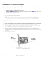
Installing The ES/Server PCI Adapter
There are three steps to successfully installing the ES/Server adapter card when used together with the
ES/Server software from Ringdale, Inc.
•
•
•
Install the ES/Server PCI adapter card in your PC
Attach the T-cable (sometimes called “the pigtail”) and twinax cable (or balun and CAT5) wiring
to the ES/Server adapter card
Installation of the ES/Server software
Each of the above steps is described below.
NOTE: Adapter cards are extremely sensitive to static electric charges. Be sure to discharge
your body’s static electricity by touching a grounded surface before handling an adapter.
INSTALLING THE ADAPTER
10
1)
Switch off all computer system components, unplug the computer, and remove the computer cover.
2)
Work in a static-free area and touch the computer chassis often to equalize static charges.
3)
Insert the ES/Server adapter card into a free PCI slot. The PCI slots are white or cream-colored.
The 15-pin D-connector should protrude through the rear of the PC chassis.
4)
Align the adapter and retaining bracket and tighten the screws to the retaining bracket. It is
important to tighten the screws because twinaxial cable is heavy enough to pull the card out of the
PCI socket.
5)
Replace the cover on the PC.
ES/Server User’s Manual
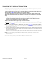
Connecting the T-cable and Twinax Cables
The following instructions assume that a twinax cable has been cabled-through from the previous
terminal on the line or directly from a port on the host system.
In order to attach your PC to the host, you need two cables: an existing host twinax cable and the
self-terminating T-cable cable included in your ES/Server package.
The T-cable cable has two ends: the 15-pin end, called the D-connector, which connects to the
adapter card, and the dual-branch end, called the T-connector, which connects to the host twinax
cable.
1. Plug the 15-pin D-connector securely into the back of the ES/Server adapter card.
To ensure good grounding, fasten the D-connector's mounting screws, making certain the
connector is firmly attached to the ES/Server adapter card.
Attach the host twinax cable to either of the T-connector branches.
NOTE: If you use baluns and CAT5 or CAT6 wiring, you should make certain that the CAT5 wiring is
at least 15 feet in length.
NOTE: If you use baluns and CAT5 or CAT6 wiring, you cannot daisy chain because the impedance
will not be unbalanced. Baluns and CAT5 wiring should only be connected in a point-to-point or
star topology with a star hub.
2. If you are cabling-through to another terminal farther down the line, attach that next terminal to
the remaining T-connector branch. Make certain that the last device on a twinax daisy chain has
properly terminated the line.
Since this is a self-terminating cable, you do not need a cap for the open end of the T-connector.
NOTE: If you are installing multiple ES/Server adapter cards, repeat steps 1 and 2 for each
adapter installed.
You are now ready to power up and install the ES/Server hardware driver.
Part Number: 62-402907301
Rev. C
Installing the ES/Server Hardware Driver
Installing the hardware driver is slightly different between the different operating systems. If you do not
direct the Windows wizard to the correct driver on the CDROM, Windows may install a default driver that
will not work, or not all. With Windows, there is always more than one correct way to install the driver.
If you are using Win98, Windows Millennium, or Windows 2000, the driver should be NLTwinax.sys
dated 12/10/2004.
If you are using Client Access on any operating system, the driver should be dated 5/20/1999 and the
driver file should be PCITwin.VxD.
If you are using Win95, or WinNT4, the driver is PCITwin.VxD dated 11/11/1998, but it shows in the
Device Manager as 5/20/1999, which is the date of the INF file.
Basic Instructions to Install the Hardware Driver
These are the basic instructions to install the hardware driver for any operating system. More complete
instructions for each operating system follow.
1)
After Windows starts up, the PC should detect the twinax card.
2)
The Windows Add New Hardware Wizard will appear. Insert the ES/Server CD into CD drive and
follow the Wizard screens.
3)
Search for a device.
4)
If you get the message “Please insert the disk labeled Win xx Drivers Disk” Click OK and Browse to
the ES/Server CD.
5)
Browse to the INF folder and then select the folder for your Windows Operating System version.
6)
When the message “Copy files from Windows” displays the correct path for the nlynx.inf file Click
OK.
12
ES/Server User’s Manual
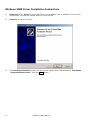
Windows XP Driver Installation Instructions
1)
Power off the PC. Insert the NLynx ES/Server Twinax adapter into an available PCI slot on the
motherboard.
2)
Power on, insert the ES/Server CDROM and logon to the PC.
3)
The Found New Hardware window will pop up in the bottom right and indicate that it has detected
a “PCI Simple Communications Controller”. Click on the window anywhere.
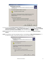
4)
It should bring up the Found New Hardware Wizard dialogue box. If it asks, “Can Windows
connect to Windows Update to search for software?” click “No, not at this time” and then
click the Next button.
5)
It should indicate the NLynx PCI Twinax Adapter. Choose the ‘Install the software
automatically (Recommended)’ option, and then click Next again.
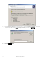
6)
It will find two drivers on the CD (Windows 98 and Windows 2000). Choose the driver for Windows
2000. Either double-click it, or click once to select it. The path to the driver should be
(D:\INF\WIN2000) Where D: is your CD-ROM drive.
7)
Click Next
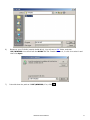
8)
It will install the driver from the CD-ROM and will tell you “The wizard has finished installing the
software for: NLynx PCI Twinax Adapter,” you finally get the Finish button. And you should
click it.
Verify the Driver
After installing the driver, you should check it to make certain it is correct.
1)
Go to the Desktop, and right-click on "My Computer", and select "Properties", which will bring up
the System Properties window.
2)
Select the “Hardware” tab, and then double-click the Device Manager button.
3)
Click on the “+” next to Twinax Adapters. Double-click on “NLynx PCI Twinax Adapter” to select
it. Select the Driver tab. For Windows XP, the driver version should be 5.0.1.7. Click on the
Driver Details button. The driver should be C:/Windows/System32/DRIVERS/nltwinax.sys.
The Driver Date will be “Not available” and the Digital Signer will be “Not digitally signed.”
If you do not have the latest driver, you can get it online at
http://www.nlynx.com/html/tb-espcidrivers.htm
ES/Server User’s Manual
13
Windows 2000 Driver Installation Instructions
1)
Power off the PC. Insert the NLynx ES/Server Twinax adapter into an available PCI slot on the
motherboard. The slots are usually white or cream-colored.
2)
Power on and logon to the PC.
3)
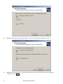
The Found New Hardware window will pop up and indicate that it has detected a “PCI Simple
Communications Device”. Click the Next button.
14
ES/Server User’s Manual
It will bring up the Found New Hardware Wizard dialogue box, and either indicates a “PCI Simple
Communications Device” or “NLynx PCI Twinax Adapter”. Choose the ‘Search for a suitable
driver for my device (recommended)’ option, and then click the Next button again.
NOTE: If the ES/Server card has been installed previously, it will indicate the “NLynx PCI Twinax
Adapter”.
NOTE: If the ES/Server card has a hardware problem, it will indicate an “Other PCI Bridge Device”. If
you get this message, contact warranty support at toll-free 888-278-9922.
ES/Server User’s Manual
15
4)
The Locate Driver Files dialogue box will come up. Insert the ES/Server CD-ROM. Remove the
check from CD-ROM Drives. Choose Specify a Location, and then click Next>.
5)
Click the Browse button.
16
ES/Server User’s Manual
6)
7)
Browse to your CD-ROM (usually the D: drive). You will see an INF folder, and then
INF/WIN2000. You should see the NLYNX INF file. Double-click on it, or click it to select it and
then click Open.
It should show the path as D:INF\WIN2000, if so, click OK.
ES/Server User’s Manual
17
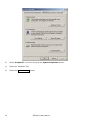
8)
Windows will search the specified location, and then compare the results to it’s own.
9)
Windows will indicate that it is going to install a driver for the PCI Simple Communications
Controller. Click Next.
18
ES/Server User’s Manual
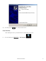
10)
You finally get the Finish option. And you should click it.
Verify The Driver
After installing the driver, you should check it to make certain it is correct.
1)
Go to the Desktop, and right-click on "My Computer".
ES/Server User’s Manual
19
2)
Select "Properties", which will bring up the System Properties window.
3)
Select the “Hardware” tab.
4)
Select the Device Manager button.
20
ES/Server User’s Manual
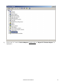
5)
Click on the “+” next to Twinax Adapters. Double-click on “NLynx PCI Twinax Adapter” to
highlight it.
ES/Server User’s Manual
21
6)
Select the Driver tab. For Windows 2000, the driver version should be 5.0.1.7. Click on the Driver
Details button. The driver should be C:/WINNT/System32/DRIVERS/nltwinax.sys. You cannot
see this here, but the INF file should be dated 10/13/2004 and the driver file should be
NLTwinax.sys dated 10/12/2004.
If you do not have the latest driver, you can get it online at
http://www.nlynx.com/html/tb-espcidrivers.htm
22
ES/Server User’s Manual
Windows 98 Driver Installation Instructions
1. Power off the PC. Insert the NLynx ES/Server Twinax adapter into an available PCI slot on the
motherboard. The slots are usually white or cream-colored.
2. Power on and logon to the PC.
3. The New Hardware Found window will pop up and indicate that it has detected a “PCI
Communications Device” and then it should bring up the Add New Hardware Wizard dialogue
box, and indicate the NLynx PCI Twinax Adapter. Choose the ‘Search for the best driver…’
option, and then click Next button.
4. When prompted for the location of the driver or INF file, insert the ES/Server CD-ROM. Choose
Specify a location, and then click on the Browse button. Double-click on the CD-ROM (usually the
D: drive). Double-click on the INF folder, and then double-click on Win98. (It may not see a file. This
is okay.)
5. You should be back at the New Hardware Found Wizard. When you have located the INF file the
Specify a location box should say D:\INF\WIN98. If this is so, you will click the Next button.
6. Windows will indicate that it is going to install the NLynx PCI Twinax Adapter and tell you that it is
going to put the driver at C:\WINDOWS\INF\OTHER|NLYNXS~1.INF. Once again you will click Next.
7. You finally get the Finish option. And you should click it.
8. After installing the driver, you should restart the PC.
Verify The Driver Installation
1)
When the PC comes back, right click the ‘My Computer’ icon and select Properties. It will bring up
the System Properties window, where you will select the Device Manager tab.
2)
Double-click on Twinax Adapters, and then double-click on the NLynx PCI Twinax Adapter.
3)
After installing the driver, you should check it to make certain it is correct.
4)
Click on the Drivers tab at the top. If you are using Windows 98, the Driver Date should be 1012-2004. If you click on the Driver File Details button, you will see
WINDOWS\SYSTEM\NLTWINAX.SYS. It should be version 5.0.1.7.
If you do not have the latest driver, you can get it online at
http://www.nlynx.com/html/tb-espcidrivers.htm
Part Number: 62-402907301
Rev. C
Windows NT Driver Installation Instructions
Windows NT is not a Plug N Play OS. Sometimes there is a setting in the BIOS for 'PnP OS -- Yes or No?'
This option is basically asking if you have a Plug and Play Operating System, (like Win98). If you select
No, the BIOS attempts to perform the Plug n Play operation. Some BIOS do not have this function and the
driver must be installed manually.
1) Insert the CDROM
2) Double-click on My Computer, then the CDROM, then go to INF/WIN95
3) Right-click on NLYNXPCI.INF and select Install. (Make certain that you RIGHT click, not left)
4) It will install the driver.
5)
Restart the PC.
6)
Check the following items:
Under Programs/Administrative Tools/Windows NT Diagnostics/Services, you should see
"Plug and Play" with a status of 'running'.
Under Programs/Administrative Tools/Windows NT Diagnostics/Resources, you should see
"pcitdlc".
Under Settings/Control Panel/Devices/ you should see a "PnP ISA Enabler driver".
Also under Settings/Control Panel/Devices/ you should see a "PCI Twinax Adapter".
Search for PCITwin.dll in the C:/Programs/ES32 folder.
Search for EMUAPP32.ini in the C:/WINNT folder.
Search for PCITWIN.ini in the C:/WINNT folder.
24
ES/Server User’s Manual
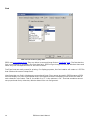
Installing The ES/Server Software
You can install the emulation software setup before installing the hardware driver, but you will not be able
to configure the software until the hardware driver is properly installed.
Installing the software is the same for Windows 9X, Windows NT and Windows 2000 users.
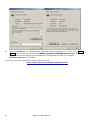
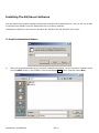
To Install the Emulation Software
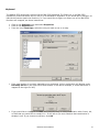
1)
After the card and hardware driver has been installed successfully, run the emulation software setup
from the ES32 folder on the CDROM. Click the Windows Start button, and then select Run.
Part Number: 62-402907301
Rev. C
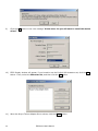
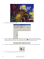
2)
Use the Browse button. You will click on My Computer, then the D: drive (or wherever your
CDROM is), then the ES32 folder, and select Setup and then click Open button.
3)
The path in the open field should be something like D:\ES32\setup.exe. If it is, click the OK
button.
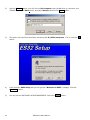
4)
It will start the ES32 Setup and you will get the “Welcome to ES32” message. Click the
Continue button.
5)
You will get the SOFTWARE LICENSE AGREEMENT. Select the Agree button.
26
ES/Server User’s Manual
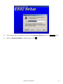
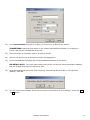
6)
It will indicate that the installation directory is C:\program files\es32. Click the Continue button.
7)
After the “Setup Succeeded” message appears, click OK .
ES/Server User’s Manual
27
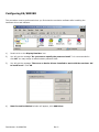
Configuring ES/SERVER
This procedure must be performed when you first start the emulation software after installing the
hardware driver and software.
1)
Double click on the Display Emulator icon.
2)
You will get the message “Do you want to specify the password now?” It is recommended to
click NO. You may assign an administrator password later.
3)
You will get the message "There are no device drivers installed to work with the emulator. OK
to install now?” Click OK.
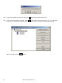
4)
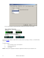
New Connection Method window will appear, click Add Driver
Part Number: 62-402907301
Rev. C
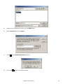
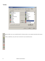
5)
Browse to the CDROM drive and go to the ES32 folder.
6)
Select drivers.tvi and click Open.
7)
Click OK to the Find Device Driver window.
8)
Click the Yes button in the ES32 window.
ES/Server User’s Manual
29
9)
Click the OK button to the next message “Please note…Do you still want to install this device
driver?”
10)
ES32 Display window will appear, if you intend to use the English USA character set, click the OK
button. If not, select the Character Set, and then click the OK button.
11)
When the NLynx Twinax Adapter Driver shows, click the Close button.
30
ES/Server User’s Manual
12)
In the Device Name field type in a name you wish to use to identify this device.
SUGGESTIONS: Match the host name or use a name that identifies whether it is a display or
printer, and has the host address at the end.
13)
Choose the type of emulation session, Display or Printer.
14)
Use the pull-down menu to choose the Model. See Appendix A.
15)
In the Host Address field select the twinax workstation address of this device.
IMPORTANT NOTE: You must make certain that you do not select a twinax workstation address
that has already been used on this twinax port.
16)
In the Keyboard field select one of the following: International World Trade or US Typewriter
(default). Click OK.
17)
You will receive the message “Would like a shortcut of this device on your desktop,” select the Yes
or No button.
ES/Server User’s Manual
31
18)
If you want to add more sessions, click the NO button and repeat steps 13-17.
19)
If you are through adding sessions, select Yes if you want to open the session, now. You may wish
to answer no, and start the software the same way that you would when starting the program.
When finished, click the Close button.
32
ES/Server User’s Manual
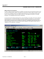
Chapter 3
RUNNING THE EMULATION ON THE ES/SERVER
At this point, you have completed the setup of ES/SERVER and are now ready to run your emulation
software on the ES/Server to test each session before installing and testing the ES/Client remote sessions.
Running ES32
Starting a session
1)
If you created a shortcut,
double click on it or go to START>PROGRAMS>ES32> and
click on Display Emulator.
NOTE: If the icon has a red triangle on the upper left, it is already being used.
NOTE: If the icon has a big red X over it, it is not able to connect with the host.
Part Number: 62-402907301
Rev. C
2)
The splash screen will come up first.
3)
When the display emulator comes up it should open the last TVD (Telnet Virtual Display) that was
opened. If it does not, and you are at a white screen, then click on the Session menu at the top, and
then choose Connect or click the icon that looks like a signon screen (sixth from the left).
4)
The device name, twinax workstation address, and connection method will show in the lower left.
5)
You will first see the dancing terminal on a gray screen.
34
ES/Server User’s Manual
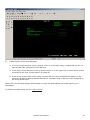
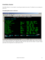
6)
A black signon screen should appear.
If you do not get a signon screen, and the cursor is in the upper right, it means that you do not
have a good cable connection to the IBM host.
If the signon screen does not come up and the cursor is in the upper left, it means that you have
connected to the host, but the session is varied off.
If the cursor bounces from left to right, it means that you have configured this session on the
same twinax station address that another device is already using or that you have configured as
the wrong device type.
Check with your IBM Host System Administrator to verify the host address and model type for your
workstation.
For further troubleshooting see the Problem Guide.
ES/Server User’s Manual
35
Status Indicators:
o
24-002 indicates the cursor is in the lower left position of the screen.
o
SA means Station Available. If this is showing, but you do not have a signon screen, it
would indicate that you are connected, but the controller is down.
o
II means Input Inhibited. You are connected to the host, but an error prevents you from
communicating. Pressing Error Reset (Ctrl) will clear this. If it recurs, do an Erase All Input,
then Error Reset.
o
IM is for Insert Mode. This allows you to insert new text, push existing text to the right.
o
KS is for Key Shift.
o
MW indicates that you have a Message Waiting.
Tips and tools:
o
Click on View and then Function Keys to get a dropdown of
common Function Keys that you can click on with the mouse.
o
Click on View and then Command Keys to get a dropdown of the Command Keys that you
can click on with the mouse.
36
ES/Server User’s Manual
Chapter 4
ES/CLIENT INSTALLATION INSTRUCTIONS
These are the complete installation instructions. There may be some minor differences
between operating system versions, and so forth that will make these instructions vary
somewhat. The important points are highlighted. If you find a question that you do not
understand, take the default.
Preparations
If none of the ES32 products were previously installed, you can start on page 2, otherwise, we
recommend removing all previous versions of ES95 (or ES32) from the computer, by using the
uninstall utility found in the ES95 (or ES32) folder.
1. Click the Windows Start button.
2. Select “Programs”, then the ES32 (or ES95), and then finally “Uninstall”.
3. You should also uninstall the hardware from the Device Manager. (If the Twinax Adapter hardware was
been done before, and the driver chosen was wrong, then you must uninstall.
4. Go to the Desktop, and right-click on "My Computer".
5. Select "Properties", which will bring up the System Properties window.
6. Select the “Device Manager” tab.
7. First look for “Twinax Adapters”, if it does not exist, then look for PCI communication device, or a
card that you do not recognize in "Other".
8. Click on the “+” next to Twinax Adapter to show the devices in this group. Click on “NLynx PCI
Twinax Adapter” to highlight it. Click the "Remove" button.
9. In some cases it is necessary to use Find or Search (whatever Bill is calling it today) on PCITwin.VxD
or NLTwinax.sys and delete them.
Part Number: 62-402907301
Rev. C
ES/Client Software Installation
1.
After the ES/Server has been installed successfully. You will install the ES/Client software on each
of the PCs. Click the Windows Start button, and then select Run.
2.
Use the Browse button. You will click on My Computer, then the D: drive (or wherever your
CDROM is), then the client folder, then disk 1, and select Install and then click Open button.
3.
The path in the open field should be something like D:\client\disk1\Install.exe. If it is, click the
OK button.
4.
It will say, “Starting setup, please wait”. It will start the ES32 Setup and you will get the
“Welcome to ES32” message. Click the Continue button.
5.
Select the Agree button, unless you don’t, in which case you have a problem.
6.
It will indicate that the installation directory is
C:\Program files\ES32. Click the Continue button.
7.
After the “Setup Succeeded” message appears, click OK.
8.
It will bring up the ES32 Client folder where you will see the Display Emulator icon.
9.
Double click on the Display Emulator icon. It will bring up the ES32 splash screen.
10.
It will say “Do you want to specify the password now?”. It is recommended to select NO to the
question. You may assign an administrator password later.
11.
It will say, “You have not configured any emulation devices. You must configure at least
one device before you can use the emulator. OK to configure now.” Click OK.
12.
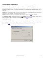
It will bring up the Configuration Properties window. Change the protocol to TCP/IP, put in the
Server Name of the ES/Server. It is important to get this name correct. It is not case sensitive.
This is seen on the ES/Server in the Server / Protocols window under the ADDRESS field.
Depending on the ES/Server configuration, this could either be the IP Address of the ES/Server or
the network name for the ES/Server.
38
ES/Server User’s Manual
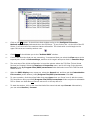
13.
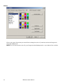
Click on the OK button. It should close that window and go to the Configure Connection
Methods and Devices window and show the ES/Server. If you click on the + to the left of the ES
Server, it will show all of the sessions that are accessible. The clients with a red triangle on the
upper left corner are used by another user.
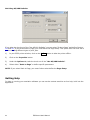
14.
Click Close. It should take you to the “Untitled-ES32” window.
15.
If this is the first time that you are connecting, I recommend that you select the View menu at the
top and put a check in Command keys, and then click it again and put a check in Function Keys.
16.
The next step of the initial configuration is to set the pointer where the TVD files (Telnet Virtual
Devices) are located. Select the Session and Properties menu, and it will bring up the browser.
Browse to the C:/Program Files/ES32/servername folder and select one of the TVD files and
double-click it.
17.
When the ES32 Display menu comes up, select the General tab, and then set the Customization
File Location (at the bottom) to C:/Program Files/ES32/servername. Click OK.
18.
To open a session, click the yellow folder that says Open when you ‘hover’ over it with the cursor.
This should now bring up the C:/Program Files/ES32/servername folder and point to selectable
TVD’s. Select one that does not have a red corner on the top left of it.
19.
To start the session, click on the icon that looks like a terminal and says Connect. Alternatively
you can select Session / Connect.
ES/Server User’s Manual
39
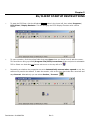
Chapter 5
ES/CLIENT STARTUP INSTRUCTIONS
1.
To start the ES/Client, click the Windows Start button in the lower left, then select Programs /
ES32 Client / Display Emulator. This will bring up the ES32 Display Emulator with a white
screen.
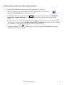
2.
To open a session, click the yellow folder that says Open when you ‘hover’ over it with the cursor.
This should now bring up the C:/Program Files/ES32/servername folder and point to selectable
TVD’s. Select one that does not have a red corner on the top left of it.
3.
Depending on whether the properties are set to Automatically connect when opened or not, the
session may need to be started. To start the session, click on the icon that looks like a terminal and
says Connect. Alternatively you can select Session / Connect.
Part Number: 62-402907301
Rev. C
ES/Client Startup Instructions When Using a VPN link
1.
Establish your Dialup Connection to your ISP. (AOL, MSN, for example)
2.
Start the VPN Client, by right-clicking on the SSH Sentinel icon on the task bar,
then choose Select VPN and put a check in the VPN.
3.
To start the ES/Client, click the Windows Start button in the lower left, then select Programs /
ES32 Client / Display Emulator. This will bring up the ES32 Display Emulator with a white
screen.
4.
To open a session, click the yellow folder that says Open when you ‘hover’ over it with the cursor.
This should now bring up the C:/Program Files/ES32/servername folder and point to selectable
TVD’s. Select one that does not have a red corner on the top left of it.
5.
To start the session, click on the icon that looks like a terminal and says Connect. Alternatively
you can select Session / Connect.
ES/Server User’s Manual
41
Chapter 6
Configuring ES32
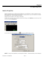
Session Properties
Session Properties can be configured at the ES/Server or the ES/Client. In order to change the look
and/or properties of anyone who uses the sessions, bring the session up on the ES/Server and make
the changes there. This will establish the default.
Changes must be made on each session individually.
Configure the properties of the emulation sessions by clicking on the Session menu at the top of the
screen and selecting Properties.
You can also click on the Properties icon
to access the ES32 Display window.
NOTE: For many of the properties, you must perform Session – Disconnect before you can change it.
Part Number: 62-402907301
Rev. C
Device Settings:
The Device Settings page shows the settings that you configured in the Configuration. You cannot
alter the settings on this page with the exception of Automatically connect when opened if you
have the session open.
To alter these settings, close the ES32 Display window (if it is open), then either click on the icon
that looks like a dark terminal and says Disconnect when you hover the mouse over it, or click on
Session and select Disconnect. After disconnecting the session, you can modify your parameters
either by Session – Properties or by File – Configure, then opening the session from the Configure
Connection Methods and Devices window.
ES/Server User’s Manual
43
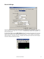
General Settings
The option “Enable Explorer extensions” allows you to create shortcuts to TVD and TVP files.
If you open the Display Emulator from the Start / Programs / ES32 / Display Emulator, the option
Open last file when started will point to the last TVD or TVP that was open.
Reconnect last file when started opens the session.
If you shut down a session without logging off, your host may require that the System Administrator
vary the session off and back on. Display warning message before disconnecting will give the
above warning to remind you to log off the host so that you will be able to log on again without
contacting the System Administrator.
Do not save customization on exit is for when you are sharing a session with other people or
when you do not want a user to change their settings.
Admin Options allow an Administrator to lock options down.
44
ES/Server User’s Manual
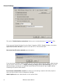
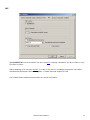
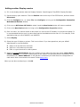
Display options
Display options are self-explanatory. Display Screen Attributes is a troubleshooting tool.
If you enable Full Screen Mode after connection you will not have your Main Toolbar, Custom
Toolbars, Command Key pad, or Function Key pad. If you enable Full Screen and wish to get the
other functions back, right-click inside the screen and take the check out of Full Screen.
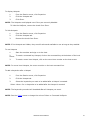
HotSpots
If HotSpots are enabled, you can click on menu options, or command options that are showing on the
screen, using the mouse.
Menu HotSpot Example:
You can click on the number 1 or click on “User tasks”, to bring up the IBM “User
Tasks” menu.
Command HotSpot Example:
Click on the F3 or Exit, to perform the Exit command.
ES/Server User’s Manual
45
You can select whether Command and Menu HotSpots will be show in this window.
Menu HotSpot Examples:
Showing
Not showing
Command HotSpot Examples:
Showing
Not showing
You can also select whether to add a CMD 4 (usually used for a prompt), an Enter, or a Field Exit after
using any HotSpot.
To enable Hotspots
1.
From the Session menu, click Properties.
2.
Click the Hotspots tab.
3.
Click Enable.
NOTE: Clicking Show highlights all Hotspots, regardless of whether they are enabled or not.
46
ES/Server User’s Manual
To display Hotspots
1.
From the Session menu, click Properties.
2.
Click the Hotspots tab.
3.
Click Show.
NOTE: The Hotspots are displayed even if they are currently disabled.
To hide the HotSpots, remove the check from Show.
To hide Hotspots
1.
From the Session menu, click Properties.
2.
Click the Hotspots tab.
3.
Remove the check from Show.
NOTE: If the Hotspots are hidden, they are still active and available to use as long as they enabled.
To use Hotspots
1.
Start the emulator and sign on to the host.
2.
To enact a command key Hotspot, click on the command key at the bottom of the host
screen.
3.
To enact a menu item Hotspot, click on the menu item number on the host screen.
NOTE: For menu item Hotspots, the cursor must be on the host command line.
To add a keystroke after a Hotspot
1.
From the Session menu, click Properties.
2.
Click the Hotspot tab.
3.
Select the keystroke you want to be added after a Hotspot is enacted.
Select <None> for no keystroke to be added after the Hotspot is enacted.
NOTE: The keystroke you select will be added after all Hotspots you enact.
NOTE: See the Colors screen to change the colors of Menu or Command HotSpots.
ES/Server User’s Manual
47
Font
This is a fun screen to play with.
ES32 uses monospaced fonts. They can either be screen bitmap fonts or TrueType fonts. The fact that the
font is monospaced is encoded in the font descriptor. ES32 will go through the list that Windows have and
select only the monospaced fonts for the user to select.
TrueType fonts are really meant for printing. For display purposes, the font installer will create a *.FOT file
that contains the screen bitmap fonts.
Most fonts that you find in Windows are proportional fonts. They cannot be used in ES32 because a 5250
terminal display only uses monospaced fonts. Monospaced fonts are essentially fonts where the width of
each character is the same. That is, the width of an "I" is the same as a "W". Terminal emulators cannot
use proportional fonts; otherwise, tabular data will be out of alignment.
48
ES/Server User’s Manual
API
The Enable ETU must be checked if you are using ETU. Leaving it enabled if you do not have or use
ETU does no harm.
Macro Language is for use with HLLAPI. In order to use this a C Language programmer can obtain
the Advanced Developer’s Kit from Ringdale. Contact technical support for this.
Cut & Paste allows advanced functionality to normal cut & paste.
ES/Server User’s Manual
49
Colors
Click on the type of text that you would like to change the color of, and then select the foreground
color and background.
NOTE: Do not use the same color for your foreground and background, or your data will be invisible.
50
ES/Server User’s Manual
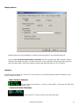
Keyboard
The default ES32 keyboard is laid out like an IBM 5250 keyboard. The Enter key on an IBM 5250
keyboard is positioned where the Ctrl key is on a standard PC keyboard. If you would like to change it so
that the key names match the functions, or if you would like to figure out where one of the IBM 5250
functions are mapped, use these instructions:
Click on the Sessions menu and select Properties.
Click on the Keyboard tab.
From the list of Host Keys, select the one you want to see or re-map.
If the host function is currently mapped to your keyboard, its key combination will display under
Currently Set To on the right side of that window. In the above example, it shows that Enter is
mapped to the right Ctrl key.
If you would like to change it click Set, then press the key, or a key combination with Control, Alt,
or Shift that you would like to remap it to. It will inform you as to whether that combination is
already in use. If you choose to continue, click OK.
ES/Server User’s Manual
51
Toolbar
In the toolbar menu you can add buttons for functions that you use regularly and desire fast access
to.
After you add them, they will show on the side of your emulation screen.
52
ES/Server User’s Manual
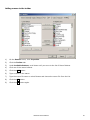
Adding another Display session
1) If it is not already started, start the Display Emulator. Start/Program Files/ES32/ Display Emulator.
2) Disconnect any open sessions. Click the Session menu at the top of the ES32 screen, and then select
Disconnect.
3) Click the Configure icon, (or select File, then Configure) to bring up the Configuration Connection
Methods and Devices window.
4) Click once on NLTwinax: NLTwin0 to select it and the New Device button will become enabled.
5) Click on the New Device button to bring up the Configuration Properties window.
6) Give it a name. You cannot choose a name that is in use on this PC already. You cannot use spaces. It
is recommended that you put in a name that has the Host Address at the end of it. For example, if the
application that you use is MAPICS, use MAPICS0.
7) Select Display.
8) Select the type of display or printer. This is not critical. If you have questions, ask your AS400
administrator or use the default.
•
•
•
3197C is an 80 wide color terminal
3197D is a 132-wide color terminal
5291 is a good terminal for older systems
9) Select an unused Host Address. On every twinax port (or cable run) there are seven ‘work station
address’ from 0 to 6. If you are checking this on the AS/400 using Display Device Description, this is
identified as the “Switch Address” on the AS/400. Sometimes you need check the configuration of
each device that is connected to the same Twinax daisy chain.
When you are done configuring it, click OK.
ES/Server User’s Manual
53
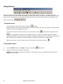
Using Macros
With the emulator you can create macros that let you perform tasks on the host. A macro is a set of
instructions that you record and then playback. Macros make it easy to perform complicated tasks or tasks
that you do over and over. You can start and stop the macros from the Macro Menu or by clicking on the
Macro tool buttons:
To record a macro
From the Macro menu, click Record or click the
button.
Perform the steps you want to record. While you are recording, any keys you press are captured and
saved for when you play back the macro.
If you want to pause the macro while you are recording, click on
menu.
Pause from the Macro Record
NOTE: You might want to pause in the middle of macro if you are recording a task that contains
sensitive information, like a sign-on procedure containing a password. You can pause the macro and,
after entering your password, click Record again to begin the recording the macro again.
When you are done, from the Macro menu, click Stop or click the stop button.
To play back a macro
1)
From the Macro menu, click Play or click on the toolbar
2)
Click the macro that you want to play back.
play option.
NOTE: You can assign macros to the Toolbar. To play back a macro, just click the Toolbar button
assigned to the macro.
54
ES/Server User’s Manual
Adding a macro to the toolbar
1)
On the Session menu, click Properties.
2)
Click the Toolbar tab.
3)
Under Available Buttons, scroll down until you come to the list of Macro Buttons.
4)
Click one of the macro buttons.
5)
Click the Add button.
6)
Type a name for the macro.
7)
Type the macro file name or select Browse and choose the macro file from the list.
8)
Click the OK button.
9)
Click the OK button again.
ES/Server User’s Manual
55
To pause a macro
1.
During playback of a macro, click Pause from the Macro menu under Play or click the
2.
Click Play to resume playback of your macro.
To edit a macro
1.
On the Macro menu, click Edit.
2.
Click the macro you want to edit.
NOTE: Macro files have .tvm extensions.
3.
Click Open.
The emulator launches the Notepad application. You will edit the macro from there.
4.
Edit the macro by:
Adding SEND, PAUSE, or HOSTKEY commands or changing the existing text in an ASCII string.
Adding LABEL and GOTO statements to make it loop.
5.
Save the macro.
NOTE: You may find it easier to record a new macro than to edit an existing one.
EXAMPLE:
HOSTKEY (Enter)
HOSTKEY (Enter)
HOSTKEY (Enter)
LABEL START
SEND 1
HOSTKEY (Enter)
SEND 1
HOSTKEY (Enter)
SEND 1
HOSTKEY (Enter)
HOSTKEY (Cmd 12)
SEND 2
HOSTKEY (Enter)
HOSTKEY (Cmd 12)
GOTO START
56
ES/Server User’s Manual
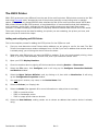
The ES32 Printer
IBM’s 5250 printers are very different from the rest of the world’s printers. IBM printers connect to the IBM
host using Twinaxial cable, whereas the rest of the printers generally connect using serial or parallel
cables. IBM printers only accept EBCDIC data, whereas the rest of the world's printers accept ASCII data.
IBM printers follow the IBM 5250 protocol, a complicated form of communications that does addressing,
error-correction, and so forth, whereas the rest of the world’s printers use more basic flow control
methods. The data formatting commands are completely different between IBM and the rest of the world.
Three main things control the data formatting, the printer you are emulating, the printer you have, and
where you plan to control the output.
Adding and configuring an ES32 Printer
This is the complete process for adding the ES32 printer for the ES/Server card.
1)
First you must determine what Twinax station address you are going to use for the card. The IBM
Twinax line supports seven station addresses from 0-6 and if you use an address that another device
is already using, you will bring the whole Twinax line down.
2)
Determine what IBM printer you want the ES32 to emulate. If you only want portrait printing, chose
5256, if you only want landscape, choose 5225, and if you want both choose 5219.
3)
Open your ES32 Display Emulator.
4)
Close the sessions down by signing off the host and then selecting Session – Disconnect.
5)
Select the File menu, then Configure, and it will bring up the Configure Connection Methods
and Devices window.
6)
Select the Nlynx Twinax :NLTwin# card, by clicking on it, then click on New Device. It will bring
up the Configuration Properties window.
7)
You must give it a name, any name, in the Device Name field.
8)
Select the Printer (vs. Display) dot.
9)
Select the Model (See Appendix B for more information on what printer to emulate).
o
o
o
10)
5256 is a portrait printer
5225 is a landscape printer
5219 is a page printer that can do both
Select the Host Address, making certain not to choose an address that another device is already
using.
Part Number: 62-402907301
Rev. C
To Open A Printer Session
1)
On the File menu, click Open Printer.
2)
In the Look In box, click the drive that contains the session you want to open. This will usually be
the C: drive.
3)
Below the Look In box, click the folder that contains the session you want to open. This will usually
be the C:\Program files\ES32 folder.
4)
Click the display session name, or type it in the File Name box.
5)
Click OK.
58
ES/Server User’s Manual
Print Data Control
The ES32 software is very versatile in controlling the data to the printer. The default is to not change the
data at all.
Formatting that occurs on the host
First the data is formatted by the application that generated the data. MAPICS, QRY or SEU for example.
You can select the form size in length and width, the form type, and the number of copies. These
parameters can be adjusted in the spool queue as well.
ES/Server User’s Manual
59
AS400 Host Print Transform
If you have an AS/400, there is a parameter that can be enabled, called Host Print Transform. Host Print
Transform is a way to allow the AS/400 to control all aspects of the print job, CPI, LPI, and special
features. It allows you to select the specific Manufacturer, Type, and Model of your printer. If this is
enabled, the data will be sent in “transparent ASCII” from the AS400. The AS400 will have already
formatted the data for your printer model. Control is then handled at the AS/400 application. This method
works quite well in applications where the user needs complete control over their device.
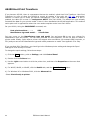
On your AS400, Using the CHGDEVPRT command, set:
Host print transform . . . . ..
*YES
Manufacturer type and model. . * YourPrinter
Put your cursor on the Manufacturer type and model line and press F4 to see your choices for
Manufacturer type and model. You can then press F1 for more specifics. You do not have to match a
printer model exactly. Quite often a printer will support other emulations (for example IBM Proprinter, or
PCL) and you can set the Manufacturer type and model parameter to match. See Appendix C for help
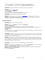
If you use Host Print Transform, you should go to the Windows printer setting and change the Spool
Settings to Print Directly to Printer.
To change the spool settings, follow these steps:
1) Click the Start button, point to Settings, and click Control Panel.
2) Double-click the Printers icon.
3) Use the right mouse button to click the printer icon, and then click Properties on the menu that
appears.
4) For Win95, Win98, or WinME, click the Details tab, and the Spool Settings button.
4) For Windows XP or Windows 2000, click the Advanced tab.
Select Print directly to printer.
60
ES/Server User’s Manual
Formatting that occurs in ES32
ES32 first looks at the data to see if “transparent ASCII” (Host Print Transform enabled) is sent.
If “transparent ASCII” (Host Print Transform) is enabled, the data is already formatted for a specific
printer and is ported straight to the printer port whether it is a parallel port, USB port, network port, or
serial port.
NOTE: If the printer that the data is sent to is not the same as the model that is selected in the AS/400
manufacturer type and model, unpredictable results may occur.
NOTE: If Host Print Transform is enabled, the ES32 Properties – Option and Font are disabled.
If “transparent ASCII” (Host Print Transform) is not enabled, then ES32 converts the EBCDIC data to
ASCII and puts the data to a temporary ‘document’ based on the SCS formatting.
Use AS/400 Defaults:
When this option is selected the emulator will scale and rotate each print job so that it will best fit onto a
piece of paper. Selecting this option may override the paper orientation you have selected from Page
Setup. If ES32 is configured to use AS/400 defaults, once a full page of data is received, that data is sent
to the Microsoft PAPI, where the data is formatted for the printer that you have selected.
ES/Server User’s Manual
61
Not Using AS/400 Defaults:
If you take the check out of the “Use AS/400 Defaults” you can select “Scale to Page” and define Custom
CPI and LPI. If you select Scale to Page, you must define the Page Setup. This option does not work well if
you are sending different types of print jobs.
1)
In your ES32 printer window, click on the Online button to take the printer offline.
2)
Click on the Properties button.
3)
Under the Options tab, take the check out of the “Use AS/400 Defaults”.
4)
Select either “Scale to Page” or define specific parameters.
NOTE: If you select Scale to Page, you must further select define the Page Setup.
Getting Help
For help on running your emulation software you can use the context sensitive on-line help, built into the
application.
62
ES/Server User’s Manual
Appendix A
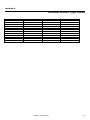
Terminal Device Type Codes
5250 Terminal Model
3179-2
3180-2
3196
3197-C
3197-D or -W
3477-FC
5251
5251-11
5291-1
5291-2
5292-1
5292 model 2
System 36 Device Code
11
15
26
16
Monitor Type
Color
Monochrome
Monochrome
Color
Monochrome
27 x 132
24 x 80
24 x 80
27 x 132
00
01
00
10
20
21
Monochrome
Monochrome
Monochrome
Monochrome
Color
Color
24 x 80
24 x 80
24 x 80
24 x 80
24 x 80
24 x 80
ES/Server User’s Manual
Size
63
Appendix B
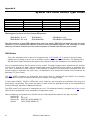
System 36 Printer Device Type Codes
5250 Printer Model
4214
5256
5224
5225
5219
3812
System 36 Device Code
PC or EA
PB or AC
PC or BB
CD
3P
3P
Format
Portrait
Portrait
Landscape
Landscape
Both
Both
Character Size
10 CPI
10 CPI
10 or 15 CPI
10 or 15 CPI
10, 12,15 CPI
10, 12,15 CPI
ES32 supports emulation for the following IBM printers:
5256 Model 1,2, or 3
5225 Model 1,2,3, or 4
4210 Model 1
5219 Model D01
5224 Model 1 or 2
3812 Model 1 (SCS Mode)
The characteristics of these IBM printers range from very simple (IBM 5256 with single line and character
densities) to very sophisticated (IBM 5219 with full word processing support). The following is a brief
summary of features available for each emulated printer as viewed from the host's point of view.
5256 Printer
This is the simplest printer in the line. It supports only 10 CPI and 6 LPI. A switch on its front panel
enables you to change to 8 LPI, but no software control is provided for this function. The System/3X or
AS/400 knows these limitations and ignores any request to alter the character or line density values.
The only available feature for this printer is form control. The page length must be specified as the number
of lines to be printed per page, while the page width must be specified as the number of characters per
line, up to a maximum of 132 columns. If any attempt is made to print beyond the horizontal limit, the
printer inserts an automatic NL (New Line). An attempt to print beyond the vertical limit introduces an
automatic FF (Form Feed).
The OCL PRINT procedure on System/36 and printer files on System/38 and AS/400 are partially
supported due to printer limitations, allowing only change of the page length.
If used under DW/36, TM/38 or Office/400, bold, underline and overstrike are available since they are
achieved by overprinting. This printer emulation is best suited for applications that do not need different
line and character densities or advanced features.
The 5256 printer only supports 10 characters per inch. This character density is mapped into a font on the
ASCII printer as specified on the workstation configuration menu.
When configuring the System/3X or AS/400 use the following device codes for this type of printer:
System/34
P
System/36
PB or AC
System/38
DEVTYPE (5256) MODEL (3)
AS/400
TYPE (5256) MODEL (3)
64
ES/Server User’s Manual
5224 and 5225 Printers
These printers are among the faster printers available for the System/3X environment. Available
features include form control, variable character density, and variable line density.
The page length must be specified as the number of lines to be printed per page, while the page
width must be specified as the number of characters per line, up to a maximum of 132 columns
at 10 CPI and 198 columns at 15 CPI. If an attempt is made to print beyond the horizontal limit,
the printer inserts an automatic NL (New Line). An attempt to print beyond the vertical limit
introduces an automatic FF (Form Feed).
The valid character densities are 10 and 15 characters per inch. These character densities are
mapped into fonts on the ASCII printer as specified on the workstation configuration menu.
A fairly wide variety of line density values are available. The most common are: 72 LPI, 48 LPI,
24 LPI, 12 LPI, 9.6 LPI, 8 LPI, 6 LPI, 5.33 LPI, 4 LPI, 3 LPI and 1 line/cm. If an unimplemented
value is requested, ES32 will approximate the requested value.
The OCL PRINT procedure on S/36 and printer files on S/38 and AS/400 are fully supported,
allowing changes to be made to character density, line density and page length. If used under
DW/36, TM/38 or Office/400, bold, underline and overstrike are available since they are achieved
by overprinting.
These printers are best suited for applications that do not require advanced highlighting features.
It should be noted that ASCII printers capable of operation faster than 2000 characters per
second may obtain higher speeds (up to 30% faster) with the 5256, 4214 or 5219 emulations,
due partially to the twinax protocol implementation on the System/3X or AS/400.
When configuring the System/3X or AS/400, use the following device codes for this type of
printer:
System/34
System/36
System/38
AS/400
2P
PC or BB (5224 only) or CD (5225 only)
DEVTYPE (5224) MODEL (2) or DEVTYPE (5225) MODEL (4)
TYPE (5224) MODEL (2) or TYPE (5225) MODEL (4)
ES/Server User’s Manual
65
5219 / 3812 Printer
This printer is one of the most sophisticated printers available for the System/3X or AS/400. It supports
several character densities, line densities, fonts and highlighting effects (underline, overstrike, superscript,
subscript, etc.).
The page length can be specified either in inches or as the number of lines per page. The page width can
be specified either in inches or as the number of characters per line. If an attempt is made to print beyond
the horizontal limits, the printer may insert an automatic New Line, if desired. Similarly, if an attempt is
made to print beyond the vertical limits, an automatic Form Feed may be inserted, if desired.
The valid character density values are 10, 12 and 15 CPI.
Available line density values are 48 LPI, 24 LPI, 12 LPI, 9.6 LPI, 8 LPI, 6 LPI, 5.33 LPI, 4 LPI, 3 LPI and 1
line/cm.
The OCL PRINT procedure on System/36 does not support 5219 printers. This is a System/36 limitation.
Print files on System/38 and AS/400 are fully supported. Special highlighting effects include tab,
underline, subscript, superscript, indentation control and overstrike. Bold is also available by either
overprinting or using the BES/EES SCS commands.
This printer is best suited for word processing applications and, on the System/36, data processing
applications that do not require change of page parameters (unless the DP program itself produces the
required SCS commands).
When configuring the System/3X or AS/400, use the following device codes for this type of printer:
System/34
3P
System/36
PD or DA
System/38
DEVTYPE (5219) MODEL (D1)
AS/400
TYPE (5219) MODEL (D1)
NOTE: The 3812 is a laser printer that emulates a 5219 printer. Because of the additional capabilities that
a laser printer has, more features are possible, including improved font handling. This emulation does not
support IPDS (Intelligent Printer Data Stream).
66
ES/Server User’s Manual
Appendix C
AS400 Host Print Transform
What is Host Print Transform?
In order to make a physical connection to an AS400; you have to tell the host that the printer is one
of the many AS400 printer models. This defines the connectivity method, speed, and type of printer
for the host. The AS400’s Host Print Transform feature allows you to tell the AS400 what kind of
printer is actually attached. Once the AS400 knows this, it can speak to the printer in its native
language, or the language that the printer is emulating.
You will select the formatting attributes for the job at the AS400. The AS400 will format the data for
the specific printer. It will send the data to the printer using ASCII Transparency. You must know
what emulation your printer is set to. Nearly all printers can be configured to emulation at a few
other printers. The printer must be configured to match the ‘manufacturer type and model’ that you
select at the AS400. One of the most common printer emulations is the IBM Pro Printer (which is
*IBM42011 for the IBM 4201-1 Proprinter).
Part Number: 62-402907301
Rev. C
How do you enable Host Print Transform on the AS400?
For TDLC, you must enable it at the AS/400 manually. This is the procedure.
1)
On your AS400, Using the CHGDEVPRT command, set:
Host print transform . . . . .. *YES
Manufacturer type and model. . *SAME
2)
Place the cursor on the “Manufacturer type and model. . *SAME” line.
Press F4, which will bring up the Specify Value for Parameter MFRTYPMDL. This is where you
can see your choices for Manufacturer type and model. For example: *IBM2380, *HPII,
*HP5SI...
3)
If you want more information on what one of these choices support, you can use F1 on this
screen. You do not have to find your exact model. For instance, if you have an HP printer it
is likely that any of the lower level HP selections will work, like HPII or HPIII, because all HP
printers support Hewlett Packard printer language PCL, and the difference between them is
in the options that are supported.
4)
Once you have chosen a printer to try, you must type that in on the Manufacturer type and
model field.
What does the AS400 do when Host Print Transform is select?
The AS400 Operating System inserts a code to tell the peripheral that the data is ASCII instead of
EBCDIC, and it will send the data as ASCII, which the printer control codes that are native to the
printer that was selected. In the 5250 to S/36, S/38, & AS/400 Product Attachment Information, IBM
refers to the command as ASCII Transparent (ATRN), format = x'03nnxx'. nn is the number of
characters (in hex) to be transferred.
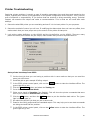
Is there anything that I have to do in the PC printer setup to enable Host Print Transform?
Yes, if you use Host Print Transform, you should go to the Windows printer settings and change the
Spool Settings to RAW where it will Print Directly to Printer.
To change the spool settings, follow these steps:
1) Click the Start button, point to Settings, and click Control Panel.
2) Double-click the Printers icon.
3) Use the right mouse button to click the printer icon, and then click Properties on the menu that
appears.
4) For Win95, Win98, or WinME, click the Details tab and the Spool Settings button.
5) For Windows XP or Windows 2000, click the Advanced tab.
6) Select Print directly to printer.
68
ES/Server User’s Manual
Appendix D
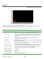
Troubleshooting
Indicators
When your signon screen does not come up. You will need to look at the following indicators to
determine what the problem is:
Cursor position: upper left, upper right, bouncing from upper left to upper right.
Status indicators at the bottom of the screen. SA, II.
Error codes in the upper or lower left corner.
Screen color: white, gray with a dancing terminal, or black.
Cursor Positions:
o
Upper right (usually accompanied by the dancing terminal) means that you do not have a
twinax connection.
o
Upper left means that you have connected to the host, but your session is varied off.
o
Bouncing from upper left to upper right means that you have a workstation address conflict
or a device mismatch.
Status Indicators:
o
24-002 indicates the cursor is in the lower left position of the screen.
o
SA means Station Available. If this is showing, but you do not have a signon screen, it
would indicate that you are connected, but the controller is down.
o
II means Input Inhibited. You are connected to the host, but an error prevents you from
communicating. Pressing Error Reset (Ctrl) will clear this. If it recurs, do an Erase All Input,
then Error Reset.
o
IM is for Insert Mode. This allows you to insert new text, push existing text to the right.
o
KS is for Key Shift.
o
MW indicates that you have a Message Waiting.
Error Codes: covered in a table in Appendix E.
Screen Color:
o
White indicates that you have not performed Session – Connect.
o
Gray indicates that the hardware has not connected.
o
Black means that you are connected and the problem is either a device mismatch or problem
at the host.
Part Number: 62-402907301
Rev. C
Problem Guide
This section contains the meaning and solutions to problems and error messages, and answers to
questions.
ES/PCI Error Messages
These are the error messages that one might encounter when installing or running the ES/Server
emulation software.
ERROR MESSAGE: “You have not configured any emulation devices. You must configure at least
one device before you can use the emulator. OK to configure now.”
CAUSE: This could happen if you did not properly name your device. You must name it. Do not use
spaces or funny characters.
CAUSE: This points to a mismatch between the hardware driver and the connection method driver.
You may have installed the wrong hardware driver. These are the drivers that must be installed
when you first bring up the PC after installing the card, but before running the setup, where you
install the connection method driver. It could also be a hardware conflict or a hardware failure.
CAUSE: This could be caused by an interrupt conflict the Windows Power Management module.
SOLUTION: Click on New Device. It will bring up the Configuration Properties menu. Select Display
or Printer if it is not already selected, and give the device a name that is indicative on the connection
method and device, like 'DSP01'0100 or 'PRT010101'. Do not use spaces or funny characters.
SOLUTION: Check the hardware driver for problems in the Device Manager. See Chapter 1.
SOLUTION: Go into the BIOS and disable Power Management functions. After you reboot, go into
the Control Panel, and change all of the power settings to Never.
ERROR MESSAGE: The Device Manager tab), for the Twinax Adapter it says:” This device has
a problem: Code=10 (0xA): : This device is not present, not working properly, or does not
have all the drivers installed.”
CAUSE: You either have not installed the hardware driver, which is located on the CDROM in the
INF folder, or you have a hardware failure.
SOLUTION:
Install the latest hardware driver, found at http://www.nlynx.com/html/tb-espcidrivers.htm
If that does not solve the problem, call 1-888-288-9080 to make a warranty claim. Have your serial
number handy. It is on the card guide where you can see it from the back of the PC.
ERROR MESSAGE: The Device Manager tab), for the Twinax Adapter it says: “Other PCI
Bridge”.
CAUSE: You have a hardware failure.
SOLUTION: Call 1-888-NLynx67 to make a warranty claim. Have your serial number handy. It is on
the card guide where you can see it from the back of the PC.
70
ES/Server User’s Manual
ERROR MESSAGE: After it is installed, it errors out and reports ”Unable to find configuration
information for connection method named”.
CAUSE: Several things can cause this problem. It points to a problem with the hardware or drivers.
It could be the wrong drivers were chosen. The Win98, WinNT, and Win2K all use the driver dated
4/19/2000. If you see the 5/20/1999, you have the ClientAccess version.
SOLUTION: Uninstall the ES32 software.
1)
Click the Start button then Programs then ES32 and then Uninstall.
2)
Remove the (hardware) driver:
3)
Click the Start button then Settings then Control Panel.
4)
Click System and the Device Manager tab.
5)
Double-click Twinax Adapters and it should show the NLynx Twinax Adapter.
6)
Click once on it to select it and then click on the Remove button the bottom of the window.
7)
Recycle power.
8)
Reinstall using the directions on the CD-ROM ESPCI.doc being careful to select the correct
driver for your operating system, which is the one in the INF/WinXX folder.
ERROR MESSAGE: After it is installed, it errors out and reports “Unable to start session” or
“Error FFFB.. VDI_Err_No_Free_Session = -5 FFFB;Error - No Free Session”.
CAUSE: You installed the ClientAccess version of software from the ES32CA folder.
SOLUTION: Uninstall the ES32CA software.
1) Click the Start button then Programs then ES32 and then Uninstall.
2) Recycle power.
3) Reinstall from the ES32 folder.
ERROR MESSAGE: Popup screen: "FAILED TO UPDATE SYSTEM REGISTRY" and On ES32
shutdown: "Unable to save C:\program files\es32\***.TVD Error: (5) Access is denied." The
two options are Retry and Cancel. Only cancel works.
CAUSE: Windows 2000 Professional and Windows XP has an option to prevent users from writing to
the registry.
SOLUTION: 1) No harm is done and these error messages can be ignored. 2) Define all users of the
ES/Server card as at least a Standard user in the Power User Group under the Control Panel’s Users
and Password settings for Group Membership or ignore these messages, 3) upgrade to version
5.0.1.6 or greater or 5) you can get rid of the ES32 shutdown message by changing the ES32
Display option: "Do not save customizations on exit". Do this by selecting File/Configure, and then
select the Options button.
ES/Server User’s Manual
71
ERROR MESSAGE: “Unable to write this configuration please re-configure” or "Unable to write
configuration file"
CAUSE: You do not have the hardware drivers installed. You must install the correct driver for your
operating system. This happens when you first put the card in.
SOLUTION:
Remove the card from the Device Manager and re-start the PC. The Windows Add New Hardware
Wizard will appear. Insert the ES/Server CD into CD drive and follow the Wizard screens.
When you get the message “Please insert the disk labeled Win xx Drivers Disk” Click OK and Browse
to the ES/Server CD. Browse to the INF folder and then select the folder for your Windows Operating
System version. When the message “Copy files from Windows” displays the correct path for the .inf
file Click OK. See more specific instructions at the beginning of this manual.
ERROR MESSAGE: "System Standby Failed. The device driver for the 'NLYNX PCI Twinax
Adapter' device is preventing the machine from entering standby. Contact your vendor." OR "The
device driver for the 'Nlynx PCI Twinax Adapter'’ device is preventing the machine from entering
hibernation. Please close all applications and try again. If the problem persists, you may need to
update this driver." This occurs even when the software is not running.
CAUSE: The ES/Server ’s driver software is always active. When the ES/Server card’s driver is
loaded, at PC boot time, and loads the microcode onto the board, it starts the session to the AS/400.
If you go to hibernation mode then there is no power on the PC and the PCI board will be unable to
answer polls from the AS/400. If that is the case then the session will be disconnected, and will have
to be restarted when the PC comes out of hibernation mode. This will be unacceptable in the AS/400
environment. The PCI board has to answer polls all the time even if the session is not active.
SOLUTION: On Windows 2000 and XP, you would have to disable standby and hibernation. You
could use a password on your screen saver for security.
On NT you can stop this by changing the start up of the device from automatic to manual.
ERROR MESSAGE: When I try to open my session, it says, "The device name xxxxx is in use".
CAUSE: If you open display2 from display1 then close down display2 last AND you also have the
parameter "Open last file when started" enabled, it will make display1 open display2.
SOLUTION: Open Notepad (Start/Programs/Accessories/NOTEPAD)
Open the TVD file that you open first. (File/Open, change the Files of Type to All Files, then
browse to Desktop (click on the desktop icon at the top), then My Computer, select the C: drive,
then Program files, then ES32/ and finally display1.TVD
It will bring up a file that has a parameter HostLinkName= display1 at the top. This needs to match
the name of the TVD file.
PREVENTION: After bringing up the Display Emulator, go to each of your sessions and select the
Session/Properties menu.
Select the General tab.
Remove the check from "Open last file when started"
72
ES/Server User’s Manual
PROBLEM: You are doing a new installation or have upgraded the operating system. After you
install the software, you start the Display Emulator and when it brings me to the "Configure
Connection Method and Devices" window, there are no devices under "This Computer" or the device
that is there is X'd out. You can't select Add/Remove Method or New Device, because they are
grayed.
CAUSE: The ES/Server hardware driver for the operating system on this PC is not installed. Windows
could have loaded it's own default, or maybe none at all.
If you are using Windows 98, Windows 2000, or XP, the driver file should be NLTwinax.sys.
If you are using Client Access on Windows 95 or Windows 98, the driver file should be PCITwin.VxD.
If you are using Win95, or WinNT4, the driver file should be PCITwin.VxD.
SOLUTION:
Reinstall the hardware driver. The hardware driver is located in the INF folder on the CDROM. You
should uninstall and delete any incorrect drivers. Please follow the Preparations Instructions in
Chapter 1.
PROBLEM: It did not bring up the Add Hardware Wizard when the card was inserted. After you reboot the PC, it is registering a hardware conflict. This could be something like "FDC Failure" or it
would lock up while trying to load 'msmouse.vxd'. It may freeze up.
CAUSE: BIOS PnP is set to No for the PCI slot that you put the card in.
SOLUTION: You must enable Plug'n'Play in the BIOS for the PCI slot that the ES/Server card is in.
Power up the PC and go into the BIOS SETUP. Usually you will press the Del key right after powerup. Here is listing of some of the key combinations used to enter the BIOS setup on startup. You
must do this during the first few seconds after you turn on power. If you see the Windows startup,
it's too late.
Award Bios=Ctrl-Alt-Esc
AMI Bios and Award Bios and others=Del (most common)
Compaq=F10
Dell=Ctrl-Alt-Enter
Dell=Reset (Twice)
HP Pavillion= Esc then F1
NEC=F2
Phoenix Bios=Ctrl-Alt-S
Phoenix Bios=Ctrl-Alt-Ins
PS/2=Ctrl-Alt-?
PS/2=Ins
Toshiba=Esc
Toshiba=F1
With the Award BIOS you will go to PNP/PCI CONFIGURATION and set PnP OS Installed to Yes.
ES/Server User’s Manual
73
QUESTION: How do I figure out what name it will be provided by the host?
ANSWER: It depends on whether you are running SSP (Advanced System/36) or OS/400 (AS/400’s)
If the OS is SSP, you use CNFIGSSP to configure or see what the device name is.
http://www.nlynx.com/html/tb-configsys36.htm
If OS/400, then the answer depends on whether you use autoconfigure (system value: QAUTOCFG)
and if you do, what the device naming parameter is set to. (system value: QDEVNAMING).
QDEVNAMING must be one of the following values:
o
*NORMAL. Naming conventions must follow AS/400 standards. The following are examples of
names following AS/400 standards:
Display Stations DSP01, DSP02
Printer
PRT01, PRT02
o
*S36. Naming conventions should follow System/36 standards. The following are examples of
names following System/36 standards:
Display Stations W1, W2
Printer
P1, P2
o
DEVADR. Device names are derived from device addresses. The following are examples of
names following the device address naming conventions:
Display Stations DSP010000, DSP010403
Printer
PRT010302, PRT010502
PROBLEM: You upgraded your Windows operating system to Windows 2000. When you start the
Display Emulator and when it brings me to the "Configure Connection Method and Devices"
window, there are no devices under "This Computer" or the device that is there is X'd out.
CAUSE: The ES/Server driver needs to be correct for the Windows operating system on this PC.
SOLUTION: Go to the Device Manager for that operating system and check what driver you have.
If you are using Win98, Windows Millennium, or Windows 2000, the driver should be
NLTwinax.sys.
If you are using Client Access on any operating system, the driver file should be PCITwin.VxD.
If you are using Win95, or WinNT4, the driver file should be PCITwin.VxD.
Latest and greatest driver is located at:
http://www.nlynx.com/html/tb-espcidrivers.htm
PROBLEM: You ran the configuration and there was no conflict, no problems. You get to the
emulation screen, but it is blank. The SA (Station Available) indicator is lit. The cursor stays upper
left.
CAUSE: Top left means that your station is not varied on. This can happen if you disconnect when
you are not at the signon screen.
SOLUTION: If the last device using this station address crashed, the station address will be varied
off. Ask the System Administrator to vary your device on. This may require varying off, and then
back on.
PROBLEM: You ran the configuration and there were no conflicts. You get the black emulation
screen, but it is blank. The SA (Station Available) indicator is not lit. The cursor stays upper right.
CAUSE: No Station Available indicates that the card does not have a connection to the Midrange
host. You probably have a twinax connection, but there is not a connection to the host. This could be
a controller problem if you are at a remote site.
SOLUTION(s): Make certain the controller is connected to the host and varied on.
74
ES/Server User’s Manual
PROBLEM: You ran the configuration and there were no conflicts. When you go to connect, the little
PC is just dancing with the AS/400 but it does not give the black screen. The cursor is in the upper
right.
CAUSE: This indicates that you do not have a connection to the twinax line.
SOLUTION(s):
Make certain that the ES/Server card is screwed in tightly. Twinax cables are heavy enough to
pull them out of the socket.
Make certain that the T-cable is screwed on tightly. The T-cable should be black.
Check the Twinax cable. Make certain there are no bent or recessed pins, and that it is keyed
correctly. Swap if possible.
Check the terminate switch on any terminals before and after your connection on a daisy chain.
The last device, furthest from the host, and only the last device, must terminate the Twinax
line. Most T-cables self-terminate.
If you have baluns and CAT5 or CAT6 wiring, make the CAT5 wire must have a minimum of 15
feet. Make certain that the polarity and pins of your baluns match your CAT5 wiring.
Make certain that you have a valid workstation address and that the device type matches the
host or that the host is set to auto configure. WRKSYSVAL QAUTOCFG
Check for system error messages. If you are connected to a remote controller, it might be
varied off.
Trying swapping with known good hardware.
Make certain that the device type for the terminal that worked, is the same as the terminal that
you configure the ES/Server to emulate.
PROBLEM: You ran the configuration and there were no conflicts. You get your signon screen, but it
goes away and comes back, goes away and comes back. Someone is screaming in the background.
CAUSE: You have taken the same WorkStation Address as someone else on the same Twinax line
that you are on.
SOLUTION(s): Ask the System Administrator what Work Station Addresses are available. Twinax
station addresses are numbered from 0-6. On the AS/400 this is the Switch setting. You must follow
the Twinax cable and check each devices switch or configuration to verify what address(es) each
device is taking. Many devices will take more than one station address.
PROBLEM: You get your emulation screen, but it is gray, not black, with the cursor in the upper left.
The SA (Station Available) indicator is on. Top left means that your station is not varied on. Host
shows Vary On Pending. No system messages.
CAUSE: The SA indicates that we can see the host, but the cursor in the upper left indicates the host
did not see us. This could be bad hardware, but it is probably a cable termination problem.
SOLUTION(s):
If you are daisy chaining, make certain that the last device is terminating the line. You cannot daisy
chain if you are using CAT5 wiring and baluns.
Double-check the twinax connections. Make certain the twinax pins are not recessed. Make certain
the T-cable is screwed on tight.
ES/Server User’s Manual
75
PROBLEM: You want to change the IRQ from 3 to 5. It is causing a conflict with the modem or
something.
CAUSE: You cannot change the settings because that is a PnP board and Windows controls the
resources.
SOLUTION: Move to a different PCI slot. You can go into the Device Manager, and remove the check
from Use automatic settings, but this is for experts. Not recommended. Not supported.
PROBLEM: It is not getting a connection. No cursor is visible. Attached to a remote 5494 controller.
Display is configured as 3477.
CAUSE: Some controllers do not support 3477 emulation.
SOLUTION: Change the description to 3197C.
PROBLEM:
After installing the software, you cannot select the Host Address that you need.
CAUSE: Having a "TVD" file with the same host address still resident on your PC would cause this.
SOLUTION: Uninstall the ES32 software. Start/Programs/ES32/Uninstall. (Do not recycle yet).
Remove the driver. Start/Settings/Control Panel/System/Device Manager. Select the
(NLynx) Twinax Adapter and select Remove. (Do not recycle yet).
Start > Find > Files or Folders and put *.TVD in the Named field, and Look in C: drive. Delete
all of the *.TVD files that it finds. (Do not recycle yet).
Start > Find > Files or Folders and put *.TVP in the Named field, and Look in C: drive. Delete
all of the *.TVP files that it finds.
Recycle power. Reinstall.
PROBLEM: IRQ conflicts. This category of problem can show itself in many ways. For example: after
installing the ES/Server card, sound cards or network cards no longer work or general protection
faults occur. Sometimes a problem might be tied to the start bar.
CAUSE: IRQ or Interrupt is the name of an input found on the processors which causes the processor
to suspend normal instruction execution temporarily and to start executing an interrupt handler
routine. Most devices, like sound cards, network cards, and so forth use these.
If two devices try to select the same IRQ, or if no IRQ remain available, then software conflicts
occur.
IRQ conflicts can be difficult to resolve, because they almost always involve getting into the BIOS
and there are several different BIOS formats, and because the conflicts inherently will involve
multiple manufacturers, neither of whom, knows all about the other device.
POTENTIAL SOLUTIONS:
1) Sometimes there is a setting in the BIOS for 'PnP OS -- Yes or No?' This option is basically asking
if you have a Plug and Play Operating System, (like Win98), which you do. If you select No, the BIOS
attempts to perform the Plug n Play operation. While it is technically best to answer this honestly,
sometimes you can shift things by changing the answer to the question.
2) Update your PC to the latest version of Microsoft Windows for the Operating System that you are
using.
76
ES/Server User’s Manual
PROBLEM: PC locking up. After many boot retries the PC finally booted okay.
CAUSE: Version 5.0.1.1. or below.
SOLUTION: Upgrade
PROBLEM: It keeps seeing the Windows XP Professional PC as Windows 95.
CAUSE: The emuapp32 application is set to Compatibility for Win95.
SOLUTION: Right-click on the Emuapp32 in C:\Program Files\es32. Selected the Compatibility tab,
then check Run this in compatibility for Windows 2000.
Session Questions:
QUESTION: How do I add another session?
ANSWER:
1) Close the sessions down by signing off the host and then selecting Session – Disconnect.
2) Click the Configure icon, (or select File, then Menu) to bring up the Configuration Properties
window.
3) Give it a name!
4) Select Display (or Printer).
5) Select the type of display or printer.
6) Select an unused Host Address.
7) When you are done configuring it, click OK.
QUESTION: What are the requirements of the device name?
ANSWER: It is recommended that you use a device name that has part of your IP Address or Work
Station Address at the end. For TN5250E sessions where the name provided is shown on the
AS/400, the initials or name of the user is helpful. It is also useful to reference the application that
the session is usually used for.
You can use any number and letter combinations.
You can use the characters @ $ and _.
Ten characters is the maximum for TN5250E sessions.
The characters ? < > , . / \ | and * are not accepted.
The characters ~ ! % ^ & ( ) - + = { } [ ] are accepted, but should be avoided for ES/TCP because
the character will change to # at the AS/400.
You cannot use - (dash).
You cannot use spaces for TN5250E sessions.
QUESTION: How do I add another session if I do not have any unused station addresses left?
ANSWER: Open your first session and sign on.
Do a System Request then put a 1 down there where the lines are:
1||||||||||||||||||||||||||||||||||||||||||||||||||||||||||||||||||||||
It will bring up another signon screen. To switch between them, do step 2.
QUESTION: What is the big red triangle over the left corner of my TVD or TVP icon?
ANSWER: This is the session that was opened to initially start ES32.
ES/Server User’s Manual
77
QUESTION: Why don’t I get the big red triangle over the left corner of my TVD or TVP icon on my
other open sessions?
ANSWER: If you opened them from the TVD or TVP file, you would, but if you open them from the
open Display Emulator session, using File/Open Display or the Open Another Display icon, it will not
put the red triangle there.
QUESTION 8: My shortcuts keep pulling up Untitled.
CAUSE: Invalid name.
SOLUTION:
Do not use a name with more than ten characters or a -.
Screen Questions:
QUESTION: I do not have access to the menu bars, how do I get my screen out of full screen mode?
ANSWER: Right-click in the middle of the screen.
Remove the check from Full Screen.
QUESTION: Every time I start the software, I do not have access to the menu bars, how do I get my
screen out of full screen mode?
ANSWER: Right-click in the middle of the screen.
Remove the check from Full Screen.
Now click on the Sessions menu and select Properties.
Click on the Display tab.
Remove the check from Full Screen Mode after connection.
Font Questions:
QUESTION: My local (not host) screen prints print out garbage.
CAUSE: The font that you have chosen in the ES32 setup is either not a TTF (True Type Font) or is
not loaded in the printer.
SOLUTION: All printer interfaces are different in Windows, but some printers have an option in the
printer driver to print fonts from the printer or direct from the application.
SOLUTION: Choose a different font. In ES32, click on Session, and select Properties, the Font tab.
QUESTION: Why does it not retain the column formatting when I cut and paste into a Word doc?
ANSWER: It assumes the font of the document that you paste into. If you choose EBCDIC it will
regain the columns. To see the other fonts that work, you can to the Session menu, click Properties.
Click the Font tab.
QUESTION: How do I get it to show all 132 columns?
ANSWER: You must select a model to emulate that supports wide screens. These would be 3180,
3197D, or 3477. This happens automatically with ES/TCP when you select 132 columns.
Select File then Configure.
78
ES/Server User’s Manual
Select your display. If it is not showing, click the + on the display adapter.
Click on Properties, it should bring up the Configuration Properties window.
QUESTION: I selected 3197D but I am unable to achieve a 132-col display.
ANSWER: Check your font selection.
Select Session, then Properties
Select the Font tab.
Make certain that the "Scale font to fit Window" is checked.
QUESTION: Why are there so few font options in ES32?
ANSWER: The fonts have to be True Type and monospaced (or fixed spacing) for IBM screen
emulation. Every character has to take up the same amount of space. Most fonts in use are not
monospaced. They have to be created internally.
Keyboard Questions:
QUESTION: How do I do re-map the keyboard?
ANSWER: Click on the Sessions menu and select Properties.
Click on the Keyboard tab.
From the list of Host Keys, select the one you want to map to your keyboard.
If the host function is currently mapped to your keyboard, its key combination will display under
Currently Set To.
Click Set.
Choose a different key, or a key together with Control, Alt, or Shift to remap it to and press that key
or key combination and click OK.
QUESTION: I wanted to make the left ALT key the error reset, in addition to the left control (CTRL).
I also wanted to make the right ALT key the Newline key. Whenever I try to do that, it expects ALT +
another key. Can I do what I want to do?
ANSWER: No, the Alt key by itself has a System 36 function so it cannot be used by itself, except
for the System 36 function. Not only that, but some of the old programs like DisplayWrite used ALT
letter combinations, for example ALT C to center. This particular function often will not work if the PC
has a program trap set for that key scan.
QUESTION: How do I do things like System Request and Command 13-24?
ANSWER: Easiest way is to click View then put a check in Command Keys, then click it again and
put a check in Function Keys. After that you can use your mouse.
Alternative method is to figure out where everything is mapped to the keyboard, by selecting the
Sessions menu and select Properties.
Click on the Keyboard tab.
ES/Server User’s Manual
79
QUESTION: When I try to use the /, *, -, and +, on the numeric keypad, it does not work, how do I
do re-map the keyboard to use these characters?
ANSWER: Those characters are assigned by default to the Duplicate, Jump, Field Minus, and Field
Plus functions.
Click on the Sessions menu and select Properties.
Click on the Keyboard tab.
From the list of Host Keys, select the one you want to map to your keyboard.
If the host function is currently mapped to your keyboard, its key combination will display under
Currently Set To.
Click Set on the Host Key that you want to change.
Either just select Remove or Choose a different key, or a key together with Control, Alt, or Shift to
remap it to and press that key or key combination and click OK.
QUESTION: How do I perform ALT-letter combinations required by DisplayWrite36 to do functions
like ALT B for Bold.
ANSWER: The left CTRL key functions as either the CMD key or the ALT key for most of these
functions. This will work for most cases, except where the Windows OS interprets the Control/Key
sequence first. The Keyboard Driver handles this. Microsoft or the Keyboard vendor writes keyboard
Driver. Functions that would cause problems are Control/C, Control/P, and Control/V.
QUESTION: When you use DisplayWrite36, Alt/c or Ctrl/c are supposed to center text, and Alt/p or
Ctrl/p is supposed to insert a page-end. These functions do not work. All the other Alt or Ctrl key
combinations the application uses do work.
CAUSE: Windows OS interprets the Control/Key sequence first. Functions that would cause problems
are Ctrl/C, Ctrl/P, and Ctrl/V, because these are standard Copy, Print, and Paste.
SOLUTION: Use the combinations:
Shift/Ctrl/ (and the appropriate letter) to get past the Windows trap and be interpreted as the
appropriate DisplayWrite36 function. For Example:
Shift/Ctrl/C will product CMD-c that is used to produce the DisplayWrite centering command.
QUESTION: Where is the cent sign key on the ES32 emulation keyboard? Also, where is the key
that looks like an upper right corner, looks like a 7 except it is a right angle with equal sides?
ANSWER: The cent sign and logical not are not defined on the PC keyboard so there is a workaround
called 'executing a hex value'. In the example below, the upper right corner symbol is a logical not
and its hex value is 5F. To execute a hex value on the ES32 emulation software (in this case you are
trying to execute a logical NOT or hex 5F) do the following:
1. Get the emulation connected and signed on.
Go to where you want to place a hex value, click the right-side mouse button.
Select Function Keys and then Hex.
Using the number pad of the keyboard select ‘5’.
Using the alpha keys select ‘F’.
This will produce the logical NOT sign. All hex values can be done this way. The hex value for the
cent sign is 4A.
To avoid steps 1-3, you can define a key as the Hex key, by doing the following steps:
1. Go to the Properties menu by pressing the Properties icon or select Session, then Properties.
2. Select the Keyboard tab.
3. Scroll the Host Key window down to Hex, and click on it to select the key that you want to have
as your ‘Hex’ key.
4. Click Set.
5. Press a key (that will become your Hex key).
6. Click OK.
7. Click OK again.
80
ES/Server User’s Manual
Printer Troubleshooting
Resolving printer problems is usually a case of tweaking parameters here and there and examining the
output. Typically this is done in the application or the printer configuration at the AS/400. This is not our
area of expertise or responsibility. If you believe that the terminal is doing something wrong. Technical
Support can examine the output and make a recommendation. This is what we will need after each
attempt.
1. Determine what IBM printer you are emulating and see if it is the best printer for your purposes.
2. Determine method of control you will use. If modifying the data output does not have any effect, then
make certain that you have proper set up the control of the printer at that point.
3. Look at the printer definition on the AS/400 and the job definition on the AS/400. There are many
places for the AS/400 to affect the job output, make certain that you have explored them all.
Get a printer hex dump from ES32:
Put the host job that you are having a problem with in save mode so that you can send the
same job a few times.
Send that job to get a sample of failing output.
In the ES32 printer control panel, click on the Online button to take the interface offline. The
green light will go out.
Click the Properties button and select the Testing tab.
Put a check in Enable Test Mode.
Either put a check in Translate (into English). This will show the printer commands that were
sent or put a check in Print as Hex (raw data).
Click the OK button, and then the Online button to put the interface back online. The ‘green
light’ will come back on.
Re-submit the AS/400 job that you put in save mode.
Examine the failing output and the translated output. This may help you to see what commands
are being sent and find the problem.
In the ES32 printer control panel, click on the Online button to take the interface offline. The
green light will go out.
ES/Server User’s Manual
81
Click the Properties button and select the Testing tab.
Remove the check from Enable Test Mode.
Click the OK button, and then the Online button to put the interface back online. The ‘green
light’ will come back on.
Technical Support can help you to examine the traces. Fax samples of the failure (marked up as
necessary) and the test output to 512-869-2621. Alternately scan and email to
[email protected].
It may also be helpful for technical support to see the host definition and the printer definition. You
can print these by using Alt / Print Screen and either printing the result or paste into an email,
when on the appropriate screens.
82
ES/Server User’s Manual
Other Questions:
QUESTION: Does your software under printer configurations, goes it have an option to print to a file
instead of a printer?
ANSWER: ES32 uses the Windows Driver Interface. The Windows Driver Interface has an option
where you can create a file on disk. The procedure is to add a printer that does this and print to that
printer:
Click the Start button then select Settings and then Printers. This will bring up the Printers
folder.
Double-click on Add Printer to bring up the Add Printer Wizard.
Click the Next button and it gives you an option of Local or Network printer. Choose either, and then
click the Next button again.
Select the printer (usually you will choose Generic/Text Only).
There is an option to select one of the "Available ports" where you will see the option to select
FILE: Creates a file on disk.
After creating this printer, bring up the ES32 printer interface using File / Open Printer.
Click the Online button to take the printer offline (green ‘light’ goes out).
Click the Page Setup button.
In the lower right, click the Printer button.
Select the Generic/Text Only.
QUESTION: How do I get help for myself?
ANSWER: Click on the Help menu at the top right.
More documents like this can be located on our web site at
http://www.nlynx.com/html/technicalbulletins.htm
ES/Server User’s Manual
83
ES/Server Section
This section has solutions to problems that one might encounter when installing the ES/Server and
ES/Clients. It is recommended that you configure the ES/Server and establish the sessions to the
host from the ES/Server first before attempting to establish a session from a client.
The categories of problems are:
ES/Server Card Installation & Configuration Problems
ES/Server to Midrange Host Connection Problems
ES/Client Installation Problems
Network Problems
Other Problems
Make certain that you can connect to the Midrange host directly from the Server.
Establish a connection to the host from the ES/Server. If you are having problems getting your
sessions to work at the ES/Server PC, then refer to these URLs:
See also:
http://www.nlynx.com/html/tb-es3xtwinproblem.htm
Or:
http://www.nlynx.com/html/tb-espciproblem.htm
Once the sessions work at the ES/Server’s Display Emulator, disconnect the session and then make
certain that Allow remote connection is enabled in the device Configuration Properties window.
The majority of problems with the ES/Server connection are network integrity problems that do not
to do with the ES/Server per se. It will work not until both the Server PC and the client PC’s see each
other in the Network Neighborhood.
Ping from ES/Client to ES/Server.
Ping from ES/Server to ES/Client.
Look in Network Neighborhood of the ES/Server to see if the ES/Client is visible.
Look in Network Neighborhood of the ES/Client to see if the ES/Server is visible.
Broadcast from ES/Server to ES/Client to check connectivity between the LAN devices.
Use a static IP Address on the ES/Server PC Network settings for TCP/IP.
Make certain that the network protocol used is configured correctly in the server and client.
84
ES/Server User’s Manual
The ES/Server software utilizes the Microsoft RPC (Remote Procedure Call), and this is a Microsoft
product. If you get the "RPC Server not available" or any other RPC error message, go to
http://www.nlynx.com/html/tb-rpcserver.htm
The message "The type universal unique identifier (UUID) has already been registered." is referenced
on this web site: http://www.opengroup.org/onlinepubs/9629399/rpc_object_set_type.htm
In order to figure out your problem, these questions need to be answered:
What Windows OS is the PC that the ES/Server card is in?
What protocol do you use for your sessions?
What status does the ES/Server show for the sessions?
Can the ES/Server ping the clients?
Can the client ping the ES/Server?
Broadcast from ES/Server to ES/Client to check connectivity between the LAN devices.
Put the Server and Client on their own VPN.
Check the memory address for the 3 ES/PCI cards. We may need to make certain that the cards are
installed in concurrent memory addresses. This might require forcing or uninstalling devices that are
inside the concurrent space and making certain to install the ES/PCI cards before the 'offending'
device.
RPC Ping: RPC Connectivity Verification Tool - This tool confirms Remote Procedure Call (RPC)
connectivity between RPC servers and clients on a network. RPC Ping checks to see if RPC services
are responding to RPC requests from client computers. Files Required:
Server Component: Rpings.exe (for Microsoft Windows 2000 and Microsoft Windows NT)
Client Component: Rpingc.exe (for Windows 2000, Windows NT, and Microsoft Windows 95, and
Microsoft Windows 98)
Rpingc16.exe (for Microsoft Windows 3.1x clients)
ES/Server User’s Manual
85
ES/Server Card Installation & Configuration Problems
PROBLEM: You are trying to install the ES/Server ISA 3XTwin card on Windows 2000. It keeps
saying, “You have not configured any emulation devices”, but when you try to configure it, you
get a message that says “This disk contains the device driver for PCI Twinax Adapter Driver
(Windows 2000)” and you do not have a PCI card.
CAUSE: Windows 2000 does not see the ISA card.
SOLUTION: You will need to purchase an upgrade to the ES/PCI card.
PROBLEM: The ES/Client cannot establish a session with the ES/Server, but it can ping the server
and vice-versa.
CAUSE: ES/Server is not configured to allow remote connection.
SOLUTION: Click on Start / Programs / ES32/ Display Emulator.
When the Display Emulator comes up, if a session starts, close it by selecting Session/Disconnect.
Select File/Configure… and it will bring up the Configure Connection Method and Devices
window.
Click the + next to the connection to the host and it should show you the display and printer
sessions that are configured.
Look at the connections to see if the ‘sharing hand’ is holding the terminal (or printer). (This may
just look like a blue box in the lower left of the terminal). If it is not there, double-click on the
display or printer and make certain that the option to Allow remote connection is enabled in the
device Configuration Properties window.
86
ES/Server User’s Manual
ES/Client Installation Problems
PROBLEM: When you try to bring the ES/Client up, it “The RPC Server is unavailable”. You can ping
the ES/Server.
POSSIBLE CAUSE: You must create the devices with the ES/Server Display Emulator.
Either the ES/Server is not started, or the protocol (see above) that you chose at the ES/Client is not
enabled, or the ES/Server is not started.
SOLUTION: Go to the ES/Server PC and select Start/Programs/ES32/ES Server.
Select the Server menu (in the top left), and then select Protocols.
Check the “Status” column to see if the protocol that you selected at the ES/Client is available on
the ES/Server.
Check the “Connection” column to see if the protocol that you selected at the ES/Client is installed
on the ES/Server.
PROBLEM: When you try to ping the ES/Server, it reports Invalid Internet Address on PCs that
have MS Proxy client installed.
POSSIBLE CAUSE:
MS Proxy client is misdirecting the IP address.
SOLUTION:
Uninstall MS Proxy client.
PROBLEM: Error Message on ES/Server: The RPC protocol sequence is not supported or The RPC
protocol sequence is invalid.
CAUSE: A protocol sequence identifies the network protocols used to establish a connection between
the client and server parts of a distributed (RPC) application. Windows 2000 does not support a
protocol sequence used in this application.
SOLUTION: ES/Server supports IPX, NetBeui, and TCP/IP. Make certain that one of these protocols
is working in both the Server and the Client. Use that protocol in the ES/Server setup.
PROBLEM: Error Message: The interface is unknown.
CAUSE: In a distributed (RPC) application, servers present objects known as interfaces to clients.
These interfaces have unique identifiers. The distributed application tried to use an interface that
does not exist.
SOLUTION: This might occur if the Twinax connection was down.
ES/Server User’s Manual
87
PROBLEM: When you try to bring up the ES32 Client session, it says, “The RPC Protocol
Sequence is not supported”. If you continue, it would report: “You cannot modify devices for
this connection remotely. Configure the connection method on the server”.
CAUSE: The protocol that you have chosen to contact the ES/Server is not added to the client.
SOLUTION: On the ES/Server PC, verify that protocol used in the ES/Server setup are installed and
properly configured.
Click the Start button, then Settings, then Control Panel.
When the Control Panel comes up, double-click on the Network icon.
The Network panel comes up and it will show you what clients, protocols, adapters, and services you
have configured.
You will use the scroll bar to see if the protocol that you have selected at the ES/Server host is
present. This could be IPX/SPX, TCP/IP, or NetBEUI.
You can now close this out on the Server and go to the Client PC.
This process will require that you have your Operating System (Win95, Win98, WinNT, or Win2K)
diskettes handy.
Click the Add… button.
Double-click on Protocol. The network protocol that you add is specific to your network. IPX/SPX
requires a Novell network. TCP/IP is common to most networks. NetBEUI is a small, fast protocol
with no networking layer; thus, it is not routable and is often not suitable for WAN implementations.
For this example we will add NetBEUI, which a Microsoft protocol. So select Microsoft, and use the
scroll bar on the right to select NetBEUI. Select OK.
It will require you to restart your PC.
PROBLEM: The ES/Client installs without any problem. When you execute the emulator, it launches
the dial up networking dial up screen (Connect To...).
SOLUTION: Check your network settings for your adapter card. This will be in your network
settings, and your Device Manager.
PROBLEM: New installation of an ES/Client gets "RPC server unavailable".
CAUSE: The connection method properties are incorrect. The protocol, the name, or the endpoint,
do not match the host.
The server is not running.
The client cannot see the server with the protocol chosen.
SOLUTION: Use the RESYNC option to find the host.
PROBLEM: When you try to bring up the ES32 Client session, it says, "The RPC Protocol
Sequence is not supported". If you continue, it would report: "You cannot modify devices for
this connection remotely. Configure the connection method on the server".
CAUSE: The protocol that you have chosen to contact the ES/Server is not added to the client.
SOLUTION: On the ES/Server PC, verify that protocols selected in the ES/Server configuration are
installed and properly configured on the PC.
Click the Start button, then Settings, then Control Panel.
When the Control Panel comes up, double-click on the Network icon.
88
ES/Server User’s Manual
The Network panel comes up and it will show you what clients, protocols, adapters, and services you
have configured.
You will use the scroll bar to see if the protocol that you have selected at the ES/Server host is
present.
This could be IPX/SPX, TCP/IP, or NetBEUI.
You can now close this out on the Server and go to the Client PC.
This process will require that you have your Operating System (Win95, Win98, WinNT, or Win2K)
diskettes handy.
Click the Add button.
Double-click on Protocol. The network protocol that you add is specific to your network. IPX/SPX
requires a Novell network. TCP/IP is common to most networks. NetBEUI is a small, fast protocol
with no networking layer; thus, it is not routable and is often not suitable for WAN implementations.
For this example we will add NetBEUI, which a Microsoft protocol. So select Microsoft, and use the
scroll bar on the right to select NetBEUI. Select OK. It will require you to restart your PC.
Network Problems
PROBLEM: Getting an error message: "RPC SERVER IS TOO BUSY TO COMPLETE THIS
OPERATION". The ES/Server will crash. Then there is an error message on the server: "NOT
ENOUGH SERVICE AREA IS AVAILABLE TO PROCEED WITH THIS OPERATION".
POSSIBLE SOLUTIONS: Disable SPX/IPX.
Increase memory in the PCs.
Use Start/Find to locate a file named Rpcltccm.dll.
Microsoft's website links:
See if the date is at least 09/08/1999. See
http://support.microsoft.com/support/kb/articles/Q243/2/20.ASP?LN=ENUS&SD=gn&FR=0&qry=RPC%20SERVER&rnk=5&src=DHCS_MSPSS_gn_SRCH&SPR=W98SE
PROBLEM: Continually getting this error in event viewer: "RPC Server unavailable; Event ID 0
The description for the eventid (0) in source (andwtdlc) could not be found. It contains the following
insertion string. \device\comA3$01
SOLUTION: "andwtdlc.sys" is the name of the NLynx device driver for Windows NT.
COMA3$01 is the pseudo-name of the Driver for the 1st emulation board.
Look at the Control Panel>Devices to see if andwtdlc is there and if it is started.
Change the andwtdlc device to automatic start.
Replace the twinax card.
PROBLEM: You get an RPC failed error on the ES/Server PC. ES/Server has performed an illegal
operation. Details are as follows:
ES/Server caused an invalid page fault in module
SESSSRVR.DLL at 014f:10005032.
SOLUTION:
ES/Server is conflicting with other software. Identify the software. May need to shut down during
backups.
ES/Server User’s Manual
89
PROBLEM: When you try to ping the ES/Server from the ES/Client it fails on all attempts.
CAUSE: You do not have a good network connection. It could be hardware, software, or a
configuration problem, most often, the latter, but verify the hardware first. You must be able to ping
from the ES/Client to the ES/Server and vice-versa.
SOLUTION: Verify your hardware by making certain that the ES/Client can see other devices, (by
using ping) and that other devices can ping the ES/Client. Do the same with the Server.
Make certain that the IP address and Subnet mask is correct.
Make certain that the IP address is not used by another host.
Make certain that any routers do not have invalid tables. This could occur if a PC is brought from one
side of a network to another.
Make certain that the DHCP Server is up and running.
Check your hubs. See what devices you can reach, and what the AS/400 can reach, to get a clue
where the problem is. Look at the lights.
PROBLEM: Installing remote ES/Clients. When you try to run the emulation you get a message:
"RPC server is not available".
CAUSE: The ES/Server might be configured to NetBEUI. NetBEUI is not a routable protocol; in other
words, it cannot be used over a router.
SOLUTION: Change the client to TCP/IP.
PROBLEM: Getting an "RPC runtime error" on the clients.
CAUSE: This is a network problem. It might indicate a bad hub or a physical break in your LAN
connection. Typically you will not be able to ping both ways.
SOLUTION: Make certain that you can ping from client to server, and vice versa.
PROBLEM: Not working with XP. The RPC Protocol Sequence is not supported.
Trying to run NetBEUI.
SOLUTION: This is from Microsoft's web site: 1703L RPC_S_PROTSEQ_NOT_SUPPORTED
This is the procedure to set up NetBEUI on Windows XP
1. Click Start / Settings / Network Connections.
2. Click "Change settings of the connection”.
3. Click on Protocol and verify that NetBEUI is not there.
4. Click Install, then Add, and then Protocol.
5. Click "Have Disk...".
6. Browse to Valueadd/MSFT NET/ NetBEUI and select NETNBF.INF
90
ES/Server User’s Manual
PROBLEM: When you click on the Configure
button on the Server, you get "Unable to find
the display emulation dispatch interface. To connect, run the display emulator again".
Running the display emulator and configuration does not change the situation.
SOLUTION: This is the Server interface to the Client. The server is unable to create a dispatch
(send) interface to the Client."
Uninstall and Re-install the Networking components on the Client Computer. Change the Workgroup
name to Workgroup and re-start the computer. Changed the Workgroup back to your domain name
and re-start once more.
ES/Server User’s Manual
91
Other ES/Server-specific Problems
PROBLEM: Connecting to our network though a Web VPN connection and the LAN network response
has decreased significantly.
CAUSE: The problem is that the Server/Client is constantly polling each other.
SOLUTION: It is recommend that any printer sessions are connected to the ES/Server and not the
ES/Clients. This will reduce network polling for printers.
PROBLEM: Connecting to our network though a Web VPN connection and the keyboard response
seems very delayed.
CAUSE: The connection to the System 36 is Twinax. The Twinax protocol is a constantly polling
protocol. Every keystroke goes to the host and back, before ES32 can legally paint it on the screen.
SOLUTION: None.
PROBLEM: When you start your ES32 session or try to “Open a new session”, it takes you to a
folder, but the TVD files are not there.
SOLUTION:
Your TVD files will be in the C:\Program Files\es32 directory. Follow this procedure to make ES32
look in this directory first.
1) Start ES32.
2) Select Session menu at the top and then select Properties. It will bring up the ES32 display
window.
3) Click on the General tab.
4) For the customization file location, enter C:\Program Files\es32.
5) Click OK and try it.
If it does not work, go to your C:\Program Files\es32 folder and 'cut and paste' the address field of
that folder to the customization file location in the ES32 General properties.
PROBLEM: The connection between the ES/Server and the client is TCP/IP. Managed to get a
Display session sign-on screen on the client PC but when you close the emulation screen, you get an
error message, which says "emuapp32.exe - Application Error. The instruction at "0x77f64b53"
reference memory at 0xfffffffe". The memory could not be "read". Click on OK to terminate the
application."
SOLUTION: If you are using multiple cards, either separate to different PCs or increase the memory.
Make certain if using multiple cards that that IO and memory addressing is contiguous.
PROBLEM: You are connecting a NT network using NT 5.0 small business version to a entry level
AS/400 running in s/36 mode. You have installed the hardware and the software on the both the
server and two clients. You can initiate a 5250 session on the server and can open multiple sessions.
You have two clients configured. The first accesses the network remotely though a dialup session.
When you initiate the client session, you can see the session icons but the all are marked with a red
X. When you try to initiate a session on the second client that is locally connected to the network you
get the following error messages; "The RPC server is unavailable. The type universal unique
92
ES/Server User’s Manual
identifier (UUID) has already been registered”. This system was working on an earlier version of NT.
We upgraded to 5.0.
SOLUTION: The "The type universal unique identifier (UUID) has already been registered." is
referenced on this web-site:
http://www.opengroup.org/onlinepubs/9629399/rpc_object_set_type.htm".
PROBLEM: The ES/Client gets a message “Unable to find the display emulator dispatch
interface” when trying to get a connection to the server.
CAUSE: The Dispatch Interface is the Server interface to the Client. The server is unable to create a
dispatch (send) interface to the Client.
SOLUTION: This problem will probably require uninstalling and reinstalling the client. This would
usually be caused by a change at the ES/Server.
PROBLEM: The users cannot use the minus key on the number keypad as a dash. A lot of our
entries require dashes.
SOLUTION: Select Session, then Properties and go to the Keyboard tab.
Go to "Field Minus" (and also Field Plus).
Currently defined as "numeric keypad minus". Change is to something else, for example
“Alt+Numeric Keypad Minus”. This will make the minus key on the numeric keypad a real minus.
PROBLEM: How do you add a second card?
SOLUTION: If you have PCI cards, just install hardware the same as the first. If you have ISA
3XTwinax cards, then you must make certain that you change the I/O Address Settings making
certain that the I/O address is not already taken in the Device Manager.
When you insert the card, it will activate the Windows Found New Hardware Wizard. It should
identify the card as an NLynx PCI Twinax Adapter. Click the Next button.
It will recommend that you search for a driver. Click the Next button. Place a check in the "Specify
a location" option and click the Next button. When it brings up the Location dialogue box, put in
the CDROM and enter the D:\inf\win2000 and it will locate the NLTwinax.sys file. Click Next and
Finish.
Start up the ES32/Display Emulator (not the ES/Server). Select File/Configure and it will bring up
the Configure Connection Methods and Devices window and it will bring up the new card properties.
(If it did not bring up the new card, then select the existing 3XTwin card, then click Add Remove
Method. When that comes up, select the NLynx Twinax Adapter Driver, and it will ungray the Add
Card option. Select the Add Card option.) Click OK.
It will bring up the Configuration Properties for the first session. Give the session a Device Name
with the station address at the end of it.
Configure your additional sessions, making certain to select Allow Remote Connection.
Connect your Twinax cables. You must have a separate Twinax cable run for each card.
ES/Server User’s Manual
93
QUESTION: Will the ES/Client talk to the ES/Server from behind a firewall or behind a NAT router?
ANSWER: Yes, you must use TCP/IP because NetBEUI is not routable. It also depends on what
permissions you enable on the firewall.
QUESTION: What port the ES/Server uses for TCPIP? You want to use it using TCPIP over the
Internet, so you need to open up the port on your firewall.
ANSWER: The default uses port 6100 for TCP/IP.
PROBLEM:
The ES/Client runs very slow.
ANSWER: The throughput is entirely up to the integrity and bandwidth of your network. There are
many things that can affect the speed of the ES/Client. This is not our area of responsibility, but
these are most of the things that can affect throughput.
If you have a lot of activity on the Twinax line that this printer is sharing, it will slow the printer
down.
If your network, network card (in the server or printer) has problems, it can slow it down.
The network protocol that you chose could make a difference. Your choices are TCP/IP, NetBeui, or
IPX/SPX. IPX/SPX is for Novell networks. TCP/IP works on nearly any network. NetBEUI is a small,
fast protocol, it has no networking layer; thus, it is not routable and is therefore not suitable for
WAN implementations.
For printers, there are many printer settings on the PC that is networked to the printer that can
affect throughput. There are the spool settings (“spool print jobs so program finishes printing faster”,
and “start printing after first page is spooled”, or “print directly to printer”), the quality settings
(draft quality is fastest). These options are not part of ES32 and are handled by the Windows Printer
Application Program Interface. The settings can be different for each manufacturer and model of
printer.
See also:
94
http://www.nlynx.com/html/tb-es3xtwin.htm
Or:
http://www.nlynx.com/html/tb-espci.htm
And:
http://www.nlynx.com/html/tb-rpcserver.htm
And also
http://support.microsoft.com/default.aspx?scid=kb;EN-US;q155012
ES/Server User’s Manual
Appendix E
IBM 5250 Error Codes
Error Codes are four or six digit hexadecimal codes that may appear on the error line in your terminal
workstation display during operation. These codes are sent from the host system.
Refer to the Error Code Range Chart below, and then go the appropriate chart.
Error Code Range
Description of Error Code and Suggested Response
0000 to 003F
An operator error occurred during an entry operation Locate the exact
code and follow the instructions. See Operator Entry Errors Codes
0040 to 005F
An error occurred on the communication network during controller/host
communication. Check the modems, cables, line and connections to the
host system.
0060 to 0069
An operation error occurred when trying Ideographic Support. See
Ideographic Support Error Codes.
0070 to 007F
An operator error occurred. See Text Entry Assist Error Codes while using
the text processing function.
0090 to 009F
A display station operator Error Codes. See Host Support System caused
an error that involves the host system.
100000 to 10FFFF
A display station operator attempted to enter an incorrect or invalid, X.25
command or parameters from the keyboard. See X.25 Error Codes
110000 to 1FFFFF
An error was detected by the DTE or DCE X.25 Network. See sections
Call Systems and try to re-establish the communications.
400000 to 400900
Linking errors.
400A00 to 411300
XID Errors
420000 to 441200
LU6.2 Errors
540404 to 540408
LAN AS/400 attachment errors
Part Number: 62-402907301
Rev. C
0000 to 0038, Operator Entry Error Codes
Refer to the following Operator Entry Error Code Chart if the code displayed is in the range from 0000
through 003F. Note the following:
1.
If an operator entry error occurs, further input tasks are suspended until the problem is resolved. The
error might be an invalid key, input or entering data at too high a rate.
2.
In some applications you can press the HELP key to get more information about the nature of the
error.
33.. To recover from the error, press the Error Reset key at the operator workstation involved and then
the Field-, Field+, or Field Exit key to blank the field.
Operator Entry Error Code Chart
Error
Code
96
Error Description and Suggested Recovery
0000
HELP Key Not Allowed.
0001
Keyboard Overrun. Entering information at too high a rate.
0002
Invalid Scan Code.
0003
Invalid Command/PF Key
0004
Data Not Allowed in This Field
0005
Cursor in Protected Area of Display.
0006
Key Following SYS REQ Key Not Valid.
0007
Mandatory Enter Field - Must Enter Data
0008
This Field Must Have Alphabetic Characters
0009
This Field Must Have Numeric Characters
0010
Only Characters 0 Through 9 Permitted.
0011
Key For Sign Position of Field Not Valid.
0012
Insert mode--no room to insert data.
0013
Insert Mode - Only Data Keys Permitted
0014
Mandatory Fill Field - Must Fill to Exit
0015
Modulo 10 or 11 Check Digit Error. You entered data into a self-check field.
0016
F - Key Not Valid in this field
0017
To recover - press the ERROR RESET key. Enter data to the end of the field or move the
cursor to the start of the field and use
0018
Key Used to exit this field not valid
0019
DUP or FIELD-MARK keys not permitted in this field
0020
Function key not valid for right adjust field
0021
Data must be entered in this field.
0022
Status of field not known
0023
Hex Mode - Entry not valid
ES/Server User’s Manual
0024
Decimal Field - Entry Not Valid
0026
F-Key Entry Not Valid
0027
The key pressed is undefined and therefore cannot be used.
0029
Diacritic Character not valid.
0031
Data Buffer overflow
0032
MSR data error
0033
MSR data received was secured and this field was not specified for secured data.
0034
MSR data exceeds length of field. Data received from card exceeds length of field.
0035
MSR Error. Card incorrectly inserted or damaged.
0036
Cursor Select not allowed in field-exit required state.
0037
This is a non-selectable field - you've pressed cursor select.
0038
Light Pen and MSR Use Not Allowed.
ES/Server User’s Manual
97
0040 to 005F Communication Network Errors
98
Cause
Code
Description and Suggested Recovery
0040
Modem or DCE is not ready or not functioning properly. Data Set Ready (DSR) Line Inactive
(Model 01); DCE Not Ready (Model 02)
This error indicates that the modem or DCE was not ready during required intervals of normal
operation. The operating state of the modem or DCE is checked at different times, depending
on the specific link-level protocol in use.
0041
Idle condition detected (X.25 only). This error indicates that the receive line was idle for 15
or more contiguous bit-times.
0042
Receive Clock Failure This error indicates that the receive clock signal became inactive during
data transfer.
0044
30-Second Timeout (switched line only).
Indicates that no valid data has been received for 30 seconds. The DTR signal goes inactive
to disconnect the line
0045
DCE Will Not Activate (X.25 only) Indicates that either a Disconnect mode (DM) or a
DISCONNECT (DISC) command was received during the link setup sequence.
0046
Frame Reject Received. The control unit received an FRMR from the network, indicating that
an error was detected in the last frame transmitted. The error log entry of this code includes
three sense bytes, which preserve the contents of the FRMR I-field.
0047
Unexpected Disconnect Mode (DM) or DISCONNECT (DISC) Command Received. Indicates
that either a Disconnect mode (DM) or a DISCONNECT (DISC) command was received while
in information transfer state.
0048
Unexpected Unnumbered Acknowledgment (UA) Frame Received. The control unit received a
UA frame while in information transfer state.
0049
An SABME was received while the controller was in information transfer state.
0050
Ready For Sending (RFS) Error. This error occurs when either the RFS line is inactive for up
to 30 seconds while the RTS line is active or the RFS line is active when the RTS line is
inactive. (except during V.25 bis call establishment).
0051
Transmit Clock Failure. The transmit clock failed during a transmit operation.
0052
Transmit Hardware Error. The link adapter hardware failed to complete a transmit operation
within 30 seconds, but no transmit clock or other DCE signal failure was detected.
0053
Expiration of Retry Count (X.25 only). No acknowledgment of a transmission was received
within allowed timeout. (Timeout retry count (N2) and retry interval (T1) are specified in
CSU Field 7)
0054
Frame Reject Sent. The control unit has sent a link-level FRMR response to the host system
after receiving an invalid SDLC or LAPB command. Sense bytes S1, S2 and S3 preserve the
contents of the FRMR I-field.
ES/Server User’s Manual
0060 to 0069 Ideographic Errors
0060
Ideographic or Bidirectional support error. Invalid data or key pressed. To correct error, press
Error-Reset at the workstation and if it is an Ideographic error, this field only accepts doubledata characters--enter the correct data.
0061
Ideographic or Bidirectional support error. Invalid data or key pressed. To correct error, press
Error-Reset at the workstation and if it is an Ideographic error, this field only accepts
alphanumeric data--enter the correct data.
0062
The cursor is not in position to change the data type. Press Error-Reset and re-attempt.
0063
Invalid Ideographic character entered in Alternate Entry mode. Press Error-Reset.
0064
The keyboard mode does not support the key pressed. Press Error-Reset.
0065
The cursor is in a column reserved for shift-out or shift-in characters. Press Error-Reset.
0066
This is not a data character and therefore, cannot be repeated. Press Error-reset.
0067
The workstation extension character RAM is full. Press Error-Reset.
0068
The output data stream to the 3030 is not valid for extension characters. Press Error-Reset.
0069
Ideographic or Bidirectional support error. Ideographic error--The extension characters to the
3030 are undefined; Bi-directional error--a terminating character cannot be inserted. Press
Error-Reset.
0070 to 0078, Text Entry Assist Error Codes
If you are using the Display Write program and an error code in the range 0070 through 007F is displayed,
refer to the following Text Entry Assist Error Code Chart for a detailed description of the problem and a
suggested recovery action.
Text Entry Assist Error Code Chart
Error Code
Description and Suggested Recovery
0070
Word Wrap/Carrier Return Error. To recover - press the Error Reset key. For more
information, press the Help key.
0071
Command Conflict. To recover - press the Error Reset key. Try the operation again when
the operation in progress is complete.
0072
Key Not Valid For Cursor Position. To recover - press the Error Reset key. Move the cursor
to the correct position and try again.
0073
Invalid Attempt To Delete. To recover - press the Error Reset key. Press the general
prompt command key to delete or replace instruction and format change characters. For
more information, press the Help key.
0074
Invalid Entry During General Prompt. To recover - press the Error Reset key
0075
Character Not Found. To recover - press the Error Reset key. Try the operation again when
the operation in progress is complete.
0076
Continuous Insert Mode Failed . To recover - press the Error Reset key. Wait until the host
system processes the text on the screen and try again.
0077
Function Key Selection Not Valid. To recover - press the Error Reset key.
0078
Required Scale Line Not Defined to Control Unit There is an error in the application
program. No scale line is defined for this line.
ES/Server User’s Manual
99
0097 to 0099 Host Support Error Codes
Refer to the following chart if the error code displayed is in the range from 0097 through 0099.
NOTE: When one of these codes is displayed, the required host support will not be available.
Host Support Error Code Chart
Error Code
Description and Suggested Recovery
0097
Test Request Function Not Supported. Contact host system operator and determine
why the function is not supported.
0098
Undefined Hardware Error
To recover - press the Error Reset key.
0099
Host Support Not Currently Available
To recover - press the Error Reset key.
100000 to 101D00 X.25 Error Codes
When a keyboard entry error occurs while in X.25 Communication mode, a six-digit error code between
100000 and 10FFFF is displayed. Error codes along with a short description and suggested recovery
action(s) are listed below:
For errors 100200 - check the system configuration. If the settings match, press the ERROR RESET key,
check options and repeat the operation. Refer to Host Access Section for procedure on restarting
communications. If this too fails, call your System Operator.
Error Code
Description and Suggested Recovery
100000
Previous CALL command in progress. Wait until the previous call is complete, or an error
code other than 100000 is displayed.
100100
Virtual circuit already established. Wait for the virtual circuit to be detached before trying
CALL/OPEN commands. It is possible to communicate over one virtual circuit at a time.
100200
ANSWER command entered for a PVC - Permanent Virtual Circuit`.
100300
CALL command entered for a PVC - Permanent Virtual Circuit
100400
Invalid logical channel ID.
(Less than 3 characters long)
100500
Invalid logical channel ID.
(Not a hexadecimal value between 001 and FFF).
100600
Invalid password. (More than 8 characters)
100700
Invalid Host Network Address. (TO network address exceeds 15 digits)
100800
Invalid Host Address. (FROM network address exceeds 15 digits)
100900
Invalid Host Network Address
100A00
Attempt to enter manual options or flow control negotiation from the keyboard with these
parameters disabled.
10
0
ES/Server User’s Manual
100B00
Facility option entered incorrectly. (Characters entered are not hexadecimal - 0 through 9
or A through F)
100C00
Invalid packet window size option. (Less than 02)
100D00
Invalid packet window size option. (Greater than 07 with Modulo 8 specified)
100E00
Invalid packet window size option. (Greater than 15 with Modulo 128 specified)
100F00
Packet size not equal to 064, 128, 256 or 512.
101000
Invalid closed user group option. (Does not contain two decimal digits)
101100
Invalid control character entered.
101200
Host network address missing a CALL command.
101300
First control character (A, O, C or D) has already been entered.
101400
Network address was entered for a permanent virtual circuit (PVC).
101500
Password option was entered for a permanent virtual circuit (PVC)
101600
Invalid password option. (All not alphanumeric characters)
101800
Invalid password option. (All not alphanumeric characters)
101900
The Q or the E option was selected with the ANSWER command.
101A00
F or R control character entered for an ANSWER command or a PVC. [F=Facility;
R=Reversed charging].
101B00
The Q or the E option was selected with the ANSWER command.
101C00
CALL entered for an answer-only SVC.
101D00
OPEN entered for an answer-only SVC
ES/Server User’s Manual
101
Appendix F
Glossary
API –- Application Program Interface. An API is an Interface, which is used for accessing an application or
a service from a program. An API makes it possible to use programs from within programs, therefore it is
the foundation for modular systems with clearly defined Interfaces between separate components.
Balun – (BALanced UNbalanced) A device that connects a balanced line to an unbalanced line; for
example, a twisted pair to a twinaxial cable.
CPI – Characters Per Inch
Daisy chain – Twinaxial connected devices may be daisy chained together. The last device further in the
chain from the host must terminate the line so that the signal goes back to the host. T-cables auto
terminate the twinax line. When using baluns you cannot daisy chain.
Emulator - A program that allows a computer to act like a (particular brand of) terminal, e.g. a vt-100.
The computer thus appears as a terminal to the host computer and accepts the same escape sequences
for functions such as cursor positioning and clearing the screen.
ETU – Emulator Transfer Utility. This is a file transfer program that is installed on a IBM midrange host,
such as the AS/400 or Advanced System/36. http://www.ringdale.com
Font -- a set of characters that has the same typeface, style (italic, bold, etc.) and size (10,12, 24, etc.).
HLLAPI – High Level Language Application Program Interface. An IBM programming interface that allows
a PC application to communicate with a midrange application. The hardware hookup is handled via normal
micro to midrange 5250 emulation.
HotSpot – This is an area on the screen this is linked to a specific command or menu for that specific
screen so that you can activate the command or menu by clicking on it.
INF - (INFormation file) A Windows file that contains installation information.
LPI – Lines Per Inch
Midrange host -- In general, midrange refers to computers that are more powerful and capable than
personal computers but less powerful and capable than mainframe computers.
Monospaced -- A type font where all characters have the same width.
PAPI – Microsoft uses the Printer Application Program Interface to format printer data for a specific
printer using the INF for that printer.
OCL -- Object Constraint Language is an expression language that can be used to define expressions in
object-oriented models. These expressions enrich the respective model with precise and unambiguous
annotations, thus preserving precious information about the underlying business domain.
PCI -- (Peripheral Component Interconnect) the most widely used I/O bus (peripheral bus). Used in
computers of all sizes, it provides a shared data path between the CPU and peripheral controllers, such as
network, display, SCSI and RAID cards. However, with so many controller circuits built into the
motherboard, the need for vacant PCI slots in a PC has diminished considerably.
PCL -- Printer Control Language developed by Hewlett Packard and used in many of their laser and inkjet
printers. Printer Control Language (PCL) is a language (a set of command codes) that enables applications
10
2
ES/Server User’s Manual
to control Hewlett-Packard DeskJet, LaserJet, and other HP printers. Today, most computers have only PCI
slots along with one AGP or one PCI Express slot for the display adapter.
RPC -- Remote Procedure Call.
SCS – SNA Character Set is the print control language that IBM printers use.
T-cable - self-terminating twinax connector cable that connects to the adapter’s15-pin female DB
connector.
TDLC – Twinax Data Link Control.
TTF - TrueType Font – A scalable font technology that renders fonts for both the printer and the screen.
Unlike PostScript and other font technologies, in which the rendering algorithms are maintained in the
rasterizing engine, each TrueType font contains its own algorithms for converting the outline into bitmaps.
The lower-level language embedded within the TrueType font allows unlimited flexibility in the design.
TVD – Telnet Virtual Device. This is a Display Emulator session. The TVD file contains the properties.
TVP – Telnet Virtual Printer. This is a Printer Emulator session. The TVP file contains the properties.
Twinaxial cable - Abbreviated as twinax, a twinaxial cable is a cable with three conductors. Two
conductors are insulated wires in the center of the cable. The other conductor surrounds the first two
conductors and a layer of insulation separates them. Typically, twinax is used to connect AS/400 or
System/36 computers with its devices.
Twinax Controller – Twinax devices are attached to a controller. This may on the host, or on a remote
controller, for example an IBM 5494 Remote Controller.
Twinax Port – Each twinax cable is attached to a port on the twinax controller. This may be at the back
of the host, a remote controller, or on a twinax brick. They are numbered starting at port 00.
WSA – Workstation Address is the physical address (or addresses) assigned to each device that is
connected to a Twinaxial port. There are seven addresses on a Twinaxial port and they range from 0 to 6.
Also referred to as the host address.
ES/Server User’s Manual
103
Appendix G
Technical Support
Ringdale, Inc.
101 Halmar Cove
Georgetown, Texas 78638
Tel: 1-888-288-9080 or 1-512-288-9080
FAX: 1-512-826-2621
http://www.nlynx.com
http://www.ringdale.com
Before you call:
Please have the following information ready:
Your contact information.
Serial number of the adapter card. This is located on the card guide where you can see it from the
back of the PC.
Cursor position, upper right, upper left, dancing terminal.
The symptoms of the problem.
o
Does not work at all or intermittent?
o
AS/400 or System 36?
o
Certain application?
History of the Problem:
o
Did the device work for a period of time or fail immediately after installation?
o Was any PC option changed (hardware or software) prior to the problem appearing?
Address manual comments to:
Ringdale Inc.
Technical Support
101 Halmar Cove
Georgetown, Texas 78628
888-288-9080
www.ringdale.com
[email protected]
Part Number: 62-402907301
Rev. C
Appendix H
ES/Server Limited Warranty
General Terms and Conditions
Limited Product Warranty: Ringdale, Inc. warrants that for one year the PCI Hardware Product shall be
free from defects in materials and workmanship that arise under proper and normal use and service. In
the event the PCI Hardware Product fails to comply with the warranty set forth above, Ringdale, Inc. will
replace or repair the Product. End User must, however, return the Hardware Product, along with proof of
purchase, to Ringdale, Inc.
Software Warranty: Ringdale, Inc. warrants that for a period of ninety (90) days from the date of
purchase by the End User, its Software Products shall conform to its published specifications under normal
usage. RINGDALE, INC. DOES NOT WARRANT THAT THE OPERATION OF THE SOFTWARE WILL BE
UNINTERRUPTED OR ERROR FREE, OR THAT ALL SOFTWARE DEFECTS WILL BE CORRECTED. In the event
a Software Product fails to comply with the warranty set forth above, Ringdale, Inc. will replace the
product. End User must, however, return all copies of the Software, along with proof of purchase, to
Ringdale, Inc. within 90 days from the Software purchase date.
Warranty Limitations: End User's sole remedy under any Warranty provided by Ringdale, Inc. shall be
limited to the replacement or repair of the Product, or at Ringdale, Inc. 's sole discretion, a refund of the
purchase price. The End User shall pay transportation costs in connection with the return of any Product to
and from Ringdale, Inc.’s plant. RINGDALE, INC. GRANTS NO WARRANTY, EXPRESS OR IMPLIED, OTHER
THAN THE WARRANTIES STATED ABOVE. EXPRESSLY EXCLUDED ARE THE IMPLIED WARRANTIES OF
MERCHANTIBILITY AND FITNESS FOR A PARTICULAR PURPOSE. IN NO EVENT SHALL RINGDALE, INC. BE
LIABLE FOR SPECIAL, INCIDENTAL OR CONSEQUENTIAL DAMAGES, INSTALLATION COSTS, LOST
REVENUE OR PROFITS, OR ANY OTHER COSTS INCURRED AS A RESULT OF THE USE OF ANY RINGDALE,
INC. PRODUCT, WHETHER OR NOT USED IN ACCORDANCE WITH INSTRUCTIONS.
ES/Server User’s Manual
105