1
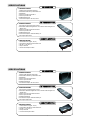
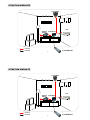
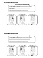
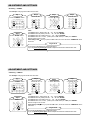
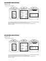
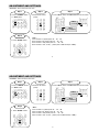
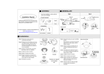
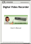
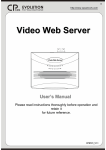
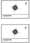
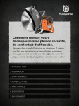
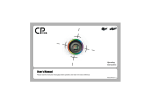
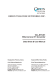
IR REMOTE CONTROL SYSTEM
USER’S MANUAL
User’s Manual
Please read this instruction thoroughly before operation
and retain it for future reference.
601 V1.2
IR REMOTE CONTROL SYSTEM
USER’S MANUAL
User’s Manual
Please read this instruction thoroughly before operation
and retain it for future reference.
601 V1.2
Thank-You Note Before You Get Start
First of all, we would like to express our gratitude to you for purchasing CPcam
products. Once again, this product is designed uniquely to meet all your personal needs
with our great industry-designing ability and our everlasting perseverance to the quality
of all our products.
This manual will introduce you how to install this camera. Please keep it well for your
future reference.
Now, we would like to invite you to personally experience this user-friendly manual and
all of the powerful functions this CPcam product offers.
http://www.cpcamcctv.com
WARNING
All the safety and operating instructions should be read before operation. The improper operation may cause permanent damage.
•
•
•
•
•
•
**
Please lift and place this equipment gently.
Do not expose this equipment to open sunlight.
Do not use this equipment near water or in contact with water.
Do not spill liquid of any kind on the equipment.
Do not attempt to have this equipment serviced by yourself.
Installation should be made by qualified service personnel.
The operating humidity is between 0%~80%.
The lightning flash with arrowhead symbol, within an equilateral triangle, is intended to alert the user to the
presence of uninsulated "dangerous voltage" within the product's enclosure that may be of sufficient magnitude to
constitute a risk of electric shock to persons.
The exclamation point within an equilateral triangle is intended to alert the user to the presence of important
operating and maintenance-(servicing) instructions in the literature accompanying the appliance.
SPECIFICATIONS
IR RECEIVER
ª SPECIFICATIONS
1.Support PTZ camera & DVR control
2.Connected to RS-485 by transmission line
3.IR Receiver
4.Control up to 255 PTZ & LIGHT
5.Control up to 255 DVR
6.Enabling different ID
7.Current Consumption: DC 12V, 25mA
ª SPECIFICATIONS
IR TRANSMITTER
1.IR control for PTZ camera, DVR, LIGHT
2.IR emission distance:straight-line is 10m; transmit at left and right 22.5
degree is 8m
3.Control up to 255 PTZ camera & LIGHT
4.Control up to 255 DVR
5.Enabling different ID
6.Current Consumption: AAA Size battery x 2
7.Not support digital zoom.
ª SPECIFICATIONS
REMOTE SWITCH
1. Home Electronics (lights, TV,etc.)
2. Connected to RS-485 by transmission line
3. DC IN x 1, DC OUT x 1
4. Output Terminal
5. Current Consumption: 50mA
1
SITUATION SIMULATE
PTZ CAMERA
DVR
REMOTE
SWITCH
: connect
: transmit
IR RECEIVER
IR TRANSMITTER
2
SITUATION SIMULATE
PTZ CAMERA
DVR
REMOTE
SWITCH
: connect
: transmit
IR RECEIVER
IR TRANSMITTER
2
RS 485
RS485-B
(green color line)
RS485-A
(red color line)
Note:
Connect “RS485-A(red color line)” to 11th aperture on DVR’s Sub-D Plug, PTZ or Remote Switch.
Connect “RS485-B(green color line)” to 10th aperture on DVR’s Sub-D Plug, PTZ or Remote Switch.
3
RS 485
RS485-B
(green color line)
RS485-A
(red color line)
Note:
Connect “RS485-A(red color line)” to 11th aperture on DVR’s Sub-D Plug, PTZ or Remote Switch.
Connect “RS485-B(green color line)” to 10th aperture on DVR’s Sub-D Plug, PTZ or Remote Switch.
3
PANEL DESCRIPTION
Preset
Light
CAMERA
DVR
1.BLUE LINE AREA – Control CAMERA
2.RED LINE AREA – Control DVR
3.OTHERS – Support CAMERA & DVR
Zoom max
4.Digital Zoom is not supported now.
Zoom min
Number selection
buttons
Zoom +
Zoom UP
Auto
Menu
Right
Left
ENTER
ID
Digital Zoom
Down
Channel selection buttons
Zoom
Rec
PIP/+
QUAD/Pause
Stop
Menu
F.F.
REW
Play
Search
4
PANEL DESCRIPTION
Preset
Light
CAMERA
DVR
1.BLUE LINE AREA – Control CAMERA
2.RED LINE AREA – Control DVR
3.OTHERS – Support CAMERA & DVR
Zoom max
4.Digital Zoom is not supported now.
Zoom min
Number selection
buttons
Zoom +
Zoom UP
Auto
Menu
Right
Left
ENTER
ID
Digital Zoom
Down
Channel selection buttons
Zoom
Rec
PIP/+
QUAD/Pause
Stop
Menu
Search
F.F.
REW
Play
4
FUNCTION DEFINITION - CAMERA
•Zoom max
Press the Zoom max button, the picture will become the biggest size directly.
•Zoom min
Press the Zoom min button , the picture will become the smallest size directly.
•Zoom + / –
Press the Zoom + or Zoom- button to change the ratio.
•Auto
Please refer to PTZ User’s Manual.
•Menu
Press Menu to enter Camera setting menu.
•Preset
Please refer to PTZ User’s Manual.
•Light
Press Light button to control remote switch (ON/OFF).
•UP, DOWN, L, and R
Press UP,DOWN,L and R to control PTZ camera.
If you press over 2 seconds, PTZ camera will move continuously.
5
FUNCTION DEFINITION - DVR
•CH1、CH2、CH3、CH4
Press Ch1- 4 to select channel.
•
/Under DVR play mode, it can display the 4 channels in QUAD mode.Under setup mode, it can decrease value.
•
/+
Under DVR play mode, it can display Picture in Picture screen. Under setup mode, it can increase value.
•Zoom
Press Zoom button to enlarge the digital picture.
•Rec
Press Rec to start recording.
•;
Under DVR play mode, it can pause the video.
•¢
Under DVR playback mode, it can stop the action.
•uu
FF: Play video fast forward.
•tt
REW: Play video fast backward.
•Menu
Press Menu button to enter DVR setting menu.
•Search
Press Search button to search.
•u
Play: Press Play to see previous recorded video.
6
ADJUSTMENT AND SETTINGS
Turning On the Power of IR TRANSMITTER
• Press DVR, CAMERA and Digital Zoom button one by one to turn on IR Transmitter.
• IR Transmitter will turn off automatically after 8 minutes if there is no operation.
Please restart again.
• If IR Receiver receives IR signal, the indicator of IR Receiver will flash.
Step
Step 11
Step
Step 22
2.Press “CAMERA” button.
1.Press “DVR” button.
Step
Step 33
3.Press “Digital Zoom” button.
7
ADJUSTMENT AND SETTINGS
Turning On the Power of IR TRANSMITTER
• Press DVR, CAMERA and Digital Zoom button one by one to turn on IR Transmitter.
• IR Transmitter will turn off automatically after 8 minutes if there is no operation.
Please restart again.
• If IR Receiver receives IR signal, the indicator of IR Receiver will flash.
Step
Step 11
1.Press “DVR” button.
Step
Step 22
2.Press “CAMERA” button.
7
Step
Step 33
3.Press “Digital Zoom” button.
ADJUSTMENT AND SETTINGS
vID Setting – CAMERA
For example: Changing Camera ID from 001 to 003
Step
Step 11
1.Press “CAMERA” button.
Step
Step 55
5.Press “ENTER” button.
Step
Step 22
2. Press”0” “0” “1”.
Step
Step 33
Step
Step 44
3. Press “ID” button.
4. Press”0” “0” “3”.
*Note :
1.If CAMERA ID is 8, please press “0”、 “0”、”8” and “ENTER”.
2.If CAMERA ID is 68, please press “0”、 “6”、”8” and “ENTER”.
3.If CAMERA ID is 168, please press “1”、 “6”、”8” and “ENTER”.
4.If CAMERA ID is 100(or 200), please press “+100” button(or “+200”) and “ENTER”.
5.The ID range is from 0 to 254.
If the setting is OK à when you press the “ID” button, the screen will show “CAMERA ID” at the
same time.
Forget
Forget the
the ID
ID
If you forget the ID(IR Receiver and Remote Switch)
àyou can press any three digits instead of Step2 and set the ID as default value ”000”.
8
ADJUSTMENT AND SETTINGS
vID Setting – DVR
Use DVR panel to set DVR ID.
Step
Step 11
1.Enter the main menu of DVR
and choose “SYSTEM”.
MENU
RECORD
CAMERA
DETECTION
DISPLAY
USER
SYSTEM
EVENT
Step
Step 22
2. Enter “REMOTE” setup.
SYSTEM
KEY MUTE
ON
BUZZER
SETUP
MESSAE LATCH
OFF
DATE DISPLAY
D/M/F
DATE
1 JAN 2005
TIME
01:38:28
HDD FORAMT
NO
SYSTEM RESET
NO
LANGUAGE
ENGLISH
UPGRADE
SETUP
REMOTE
SETUP
Step
Step 33
3. Set the REMOTE MODE as
RS-485, BAUD RATE as
2400 and DVR ID is on the
list.
REMOTE
REMOTE MODE
BAUD RATE
ID
RS-485
2400
001
•If your command to the DVR won't be recognized by the receiver, you can set DVR’s ID as default value 000.
•If the Remote Mode is RS-485, then you can’t control PTZ via DVR’s panel*.
(*When you connect IR Receiver, PTZ and DVR, then the RS-485 will just be recognized between
IR Receiver and DVR)
9
ADJUSTMENT AND SETTINGS
vFunction : How to enter the main menu
Step
Step 22
Step
Step 11
1.Press “CAMERA” button
or “DVR” button.
2.Press the ID number
(0-254) .
Step
Step 33
3. Press “Menu” button and Menu list will be on the screen.
.
.
Menu
( for DVR)
Menu
( for CAMERA)
Step
Step 44
4. Press “ENTER” button.
*Note :
1.If ID number
2.If ID number
3.If ID number
4.If ID number
is 8, please press “0”、 “0”、”8”.
is 68, please press “0”、 “6”、”8”.
is 168, please press “1”、 “6”、”8”.
is 100(or 200), please press “+100” button(or “+200”).
10
ADJUSTMENT AND SETTINGS
vFunction : How to enter the main menu
Step
Step 22
Step
Step 11
1.Press “CAMERA” button
or “DVR” button.
2.Press the ID number
(0-254) .
Step
Step 33
3. Press “Menu” button and Menu list will be on the screen.
.
.
Menu
( for DVR)
Menu
( for CAMERA)
Step
Step 44
4. Press “ENTER” button.
*Note :
1.If ID number
2.If ID number
3.If ID number
4.If ID number
is 8, please press “0”、 “0”、”8”.
is 68, please press “0”、 “6”、”8”.
is 168, please press “1”、 “6”、”8”
is 100(or 200), please press “+100” button(or “+200”).
10
ADJUSTMENT AND SETTINGS
vPreset
For example: In PTZ mode, if you want to see the 6th preset position.
Step
Step 11
1.Press “Preset” button.
Step
Step 22
vAuto
In PTZ mode, press “Auto” button and PTZ
will enter the Auto Mode.
Press any key can stop the Auto Mode.
Step
Step 11
2. Press “0”、“0” 、“6”
and it will move to the 6th
position.
Press “Auto” button.
11
REMOTE SWITCH
DC POWER INPUT
vID Setting:
The ID setting is the same as the CAMERA ID.
SET UP
(ON/OFF
Switch)
RJ-11
DC
SOURCE
+
DC LAMP
DC BUZZER
+
To DC Power Source
REMOTE
SWITCH
AC POWER INPUT
DC OUTPUT
DC INPUT
AC PLUG
N
L
L
AC LAMP
AC BUZZER
To AC Power Source
RWARNING
If the input voltage is too high, the product
longevity would be affected. And it might also
cause the product to break down.
REMOTE
SWITCH
12
REMOTE SWITCH
DC POWER INPUT
vID Setting:
The ID setting is the same as the CAMERA ID.
SET UP
(ON/OFF
Switch)
DC
SOURCE
RJ-11
+
DC LAMP
DC BUZZER
+
To DC Power Source
REMOTE
SWITCH
AC POWER INPUT
DC OUTPUT
DC INPUT
AC PLUG
N
L
L
AC LAMP
AC BUZZER
To AC Power Source
RWARNING
If the input voltage is too high, the product
longevity would be affected. And it might also
cause the product to break down.
REMOTE
SWITCH
12