1
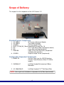
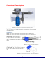
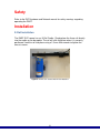
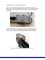
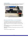
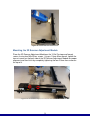
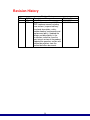
SVP-3DS
DART 3+D Scanner X-Y
User Manual
Revision 2
Document # 7.5.056
IonSense Inc.
999 Broadway
Suite 404
Saugus, MA 01906
Copyright © 2005-2015 by
IonSense Inc.
All rights reserved.
The information in this document has been carefully checked and is believed to
be reliable. However, no responsibility is assumed for inaccuracies. Statements
in the document not intended to create any warranty, expressed or implied.
Specification and performance characteristics of the hardware and software
described in the manual may be changed at any time without notice. IonSense
Inc. reserves the right to make changes in any product herein in order to improve
reliability, design, or function. IonSense does not assume any liability arising out
of application or use of any product or circuit described nor does it cover any
license under its patent rights or the rights of others.
The apparatus and application of the apparatus described in this document is
protected by US Patent Number 6,949,741 and used under license; additional
patents pending.
All trademarks are properties of their respective owners.
2
Table of Contents
Scope of Delivery
Standard System Components
Configuration Dependent Components
4
4
4
Functional Description
5
Safety
6
Installation
X-Rail Installation
Attaching the XY 2nd Rail Mount Slide
Y-Rail Installation
Mounting the DART-SVP Source on the SVP-45-A Module
Mounting the 3D Scanner Adjustment Module
Installing the Ceramic Tube
Linear Rail Settings
7
7
8
9
10
11
11
Operation
X-Y Scanner Method
12
Troubleshooting
15
Maintenance
16
Replacement Parts
17
Revision History
18
3
Scope of Delivery:
This chapter lists the components of the 3+D Scanner X-Y.
Figure 1: Scope of Delivery
Standard System Components
1.
2.
3.
4.
5.
6.
7.
JVL-2066-A
JVL-2064-A
JG10044
SHSC_SS188_M3_10mm
N/A
N/A
Z3992-00
8. JG10019
3D Scanner Adjustment Module
Tray Holder Assembly
Ceramic Cap 32.5 Deg.
Bag of M3x10 Screws Qty: 16
XY 2nd Rail Mount Slide (see below for details)
Linear Rail (see below for details)
Cable, V2.0 Linear Rail Driver (not pictured.
installed inside controller)
Graphite Vespel Ferrule (not pictured)
Configuration Dependent Components
1. SI-90XX-XX
Ceramic Tubes (see the VAPUR Interface
Ceramic Tubes Reference Sheet 7.5.038 for
lengths)
2. HW10046/47
Left/Right Handed Rail motorized 100mm
Movement
3. JVL-2068/2068-R
Left/Right Handed XY 2nd Rail Mount Slide
NOTE: Left or right hand orientation is dependent on the Mass Spectrometer.
4
Functional Description
Figure 2: 3+D Scanner X-Y (right handed configuration shown)
The 3+D Scanner X-Y enables continuous scanning across a 2 dimensional
rectangular space.
Definitions:
X Rail: The X Rail is the 300 mm rail that comes with the DART-SVP.
Y Rail: The Y Rail is the 100 mm rail that comes with the 3+D Scanner XY.
Rail Carriage: The Rail Carriage is
the part of the linear rail that moves
and has threaded holes for modules to
attach.
Figure 3: Rail with Rail Carriage highlighted
Y Rail Cradle: The Y Rail Cradle is the part of
the XY 2nd Rail Mount Slide that holds the Y
Rail.
Figure 4: XY 2nd Rail Mount Slide with Y Rail Cradle highlighted
5
Safety
Refer to the SVP Hardware and Network manual for safety warnings regarding
operating the DART.
Installation
X-Rail Installation
The DART-SVP source has an X-Rail Cradle. Simply place the linear rail directly
into the cradle on the baseplate. The rail will click into place when it is correctly
positioned. Lock the rail into place using a 1.5 mm Allen wrench to tighten the
two set screws.
Figure 5: DART-SVP Source with X-Rail Attached
6
Attaching the XY 2nd Rail Mount Slide
Place the XY 2nd Rail Mount Slide on top of the X-Rail Carriage. Using four
M3x5 screws and the 2.5mm Allen wrench loosely secure the XY 2nd Rail Mount
Slide onto the X-Rail Carriage, aligning it so that the Y-Rail Cradle covers the XRail motor.
Figure 6: XY 2nd Rail Mount Slide with the cradle covering the X-Rail Motor.
Tighten the two 1.5mm set screws on the side of the XY 2nd Rail Mount Slide
facing the DART-SVP for good alignment and then finish tightening the four
2.5mm screws on top of the XY 2nd Rail Mount Slide to finish the attachment.
Figure 7: XY 2nd Rail Mount Slide with Set Screws Circled in Red
7
Y-Rail Installation
Slide the non-motor end of the rail into the cradle, leaving it so the end of the rail
is flush with the end of the XY 2nd Rail Mount Slide. Using the 1.5mm Allen
wrench, tighten the two set screws to lock the rail in place.
Figure 8: Y-Rail installed with set screws circled in red
Mounting the DART-SVP Source on the SVP-45A Module
Pull the DART SVP source housing all of the way back from the mass
spectrometer inlet and remove the ceramic tube from the VAPUR interface.
Remove the DART-SVP source from the baseplate by unscrewing the thumb
screw.
Attach the DART-SVP source to the SVP-45A Module with the DART-SVP
source thumb screw.
Attach the SVP-45A module to the baseplate with the thumb screw on the SVP45A module.
See figure 9 on the next page for reference.
8
Figure 9: Source with SVP-45A module
Mounting the 3D Scanner Adjustment Module
Place the 3D Scanner Adjustment Module on the Y-Rail Carriage and loosely
secure it using four M3x10 hex screws. Using a 1.5mm Allen wrench, tighten the
two set screws on the back side of the 3D Scanner Adjustment Module for proper
alignment and then finish by completely tightening the four 2.5mm hex screws on
the top of it.
Figure 10: 3D Scanner Adjustment Module with set screws circled in red
9
Installing the Ceramic Tube
Insert the longer ceramic tube into the VAPUR inlet, taking care to leave a 2mm
gap between the end of the ceramic tube and the API inlet. Refer to the specific
Vapur Flange Manual for the mass spectrometer that the DART-SVP is being
installed on for more details.
Linear Rail Settings
Before running the method, be sure the Linear Rail software settings are correct.
If they aren’t the methods won’t run properly. To check, click on the Settings tab
in the software; open both Linear Rail #1 (X) and Linear Rail #2 (Y).
• For systems with linear rail part numbers HW10029 and HW10046, left
should be selected for both Motor Location and Sample From.
• For systems with linear rail part numbers HW10039 and HW10047, right
should be selected for both Motor Location and Sample From.
Figure 11a and 11b: 3+D Scanner X-Y linear rail settings (rails HW10029 & HW10046)
10
Operation
X-Y Scanner Method
Method Description:
This method enables continuous scanning across a User Defined 2 Dimensional
rectangular space. (Maximum: 109mm x 61mm) (Minimum: 1mm x 5mm). It will
scan from left to right (in right hand configuration or vice versa in left hand
configuration) for each scan at a user defined speed and temperature. Prior to
each row scan, a contact closure signal will be sent represented by the © in the
figure below.
Figure 12: X-Y Scanner Method scan path
11
Parameter Definitions:
User Defined:
Sample Count: Number of samples that will be
run. Default = 11, Range = 1-(Sample Count
Maximum), Increment = 1, Sample Count
Maximum = (Y Length – 4.6mm)/ Y Spacing
Ion Mode: Default = Positive, Other option=
Negative
Heater Temperature (C): The set temperature
for the DART heater. Default = 350; Range=0500, increment= 1
Heater Wait time (sec): The desired amount of
time at the beginning of each run to allow for the
ionization gas flow and temperature to stabilize.
A minimum of 30 seconds is recommended.
Default=30, Range=1-65563 (18 hours),
Increment=1
Contact Closure Delay (sec): The amount of
time spent sitting between samples to give time
for contact closure signals and to provide some
temporal resolution in the chromatogram.
Default=5, Range=1-65563 (18 hours),
Increment=1
X Sample Speed (mm/sec): The Speed of the
X-rail when moving from sample to sample
across the plate. Default= 2.0, Range= 0.2 -10,
Increment= 0.1
Figure 13: X-Y Scanner Method
Parameters
X Length (mm) X_dimesional_object_size: The size of the object or scanning
area in the X dimension. Default=100, Range=1-109, increment=.1
Y Length (mm) Y_dimesional_object_size: The size of the object or scanning
area in the Y dimension. Default=60, Range=5-61, increment=.1
Y Spacing (mm) Y spacing between rows: Default=5, Range = 2.5 – (Y
Length – 4.6), Increment=.1
12
Shutdown State: The system can be kept in run or standby mode for repeated
use or automatically shut down at the end of the analytical run. Default= Standby,
Other options: Off, Run
Standby Temperature (C): If the system is kept in run or standby mode, this
temperature will be maintained. It should be a little less than the start
temperature. Default=345; Range=0-500, Increment=1
Fixed (not user adjustable):
Start Position: 43.8mm
Y and X speed when not scanning: 10mm/sec
Troubleshooting
If the methods do no run correctly with respect to alignment of the sampling
areas and the exit of the DART source please read the following statements.
Please check that the carriage positions for both the X and Y rails are correct.
The measurements are taken from the edge of the linear rail carriage to either
the end of the motor for the “Home” switch position or to the end of the linear rail
for the “Limit” switch position.
Refer to page 15 in the DART-SVP Hardware and Network Installation Manual
for a visual explanation of this measurement.
X-Rail Measurements
- "Home" switch: 56 mm
- "Limit" switch: 134.5 mm
Y-Rail Measurements
- "Home" switch: 56 mm
- "Limit" switch: 44 mm
Maintenance
No special maintenance is required for the X-Y scanner.
Replacement Parts
SI-90XX-XX
Ceramic Tubes (see the VAPUR Interface Ceramic
Tubes Reference Sheet 7.5.038 for lengths)
JG10019
Graphite Vespel Ferrule
13
Revision History
REV
1
2
DCR #
43
200
Revision History
Description of Change
Initial Release
Updated format to match DARTSVP hardware manual including
new sections (scope of delivery,
functional description, safety,
troubleshooting, maintenance and
replacement parts). Updated the
photos and descriptions in the
installation section to show the
most recent version of the product.
Updated the operation section with
method descriptions from the
method definition documents.
14
Effective Date
11/11/2013
4/09/2015