1
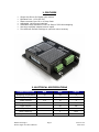
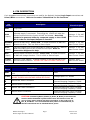
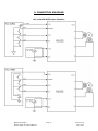
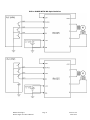
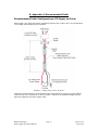
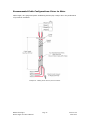
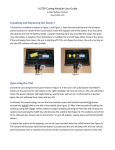
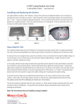
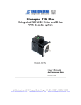
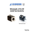
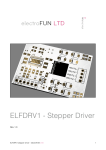
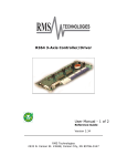
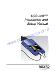
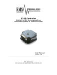
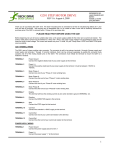
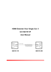
R1025 10A, 80V Microstepping Driver “The PowerHouse” User Manual Version 1.00 RMS Technologies 2533 N. Carson St. #4698, Carson City, NV 89706-0147 Thank you for purchasing the R1025 Single-Axis Step & Direction Driver. This product is warranted to be free of manufacturing defects for one (1) year from the date of purchase. PLEASE READ BEFORE USING Before you start, you must have a suitable step motor, a DC power supply suitable for the motor. The power supply voltage must be between 4 times and 20 times the motor's rated voltage. DISCLAIMER The information provided in this document is believed to be reliable. However, no responsibility is assumed for any possible inaccuracies or omissions. Specifications are subject to change without notice. RMS Technologies reserves the right to make changes without further notice to any products herein to improve reliability, function, or design. RMS Technologies does not assume any liability arising out of the application or use of any product or circuit described herein; neither does it convey any license under its patent rights, nor the rights of others. Special Symbols Indicates a WARNING and that this information could prevent injury, loss of property, or even death (in extreme cases). RMS Technologies R1025 Single Axis Driver Manual Page 2 Version 1.00 10/02/2012 R1025 User Manual Product: Version: Date: R1025 1.00 10/02/2012 Version History Version Date Description of Changes 1.00 10/02/2012 New User Manual RMS Technologies R1025 Single Axis Driver Manual Page 3 Version 1.00 10/02/2012 Table of Contents 1. FEATURES ...................................................................................... 5 2. ELECTRICAL/OPERATING SPECIFICATIONS ..................................5 3. MECHANICAL SPECIFICATIONS ..................................................... 6 4. PIN DESCRIPTIONS .......................................................................7 5. DIP SWITCH SETTINGS ............................................................. 8-9 6. CONNECTION DIAGRAMS....................................................... 10-11 7. TROUBLESHOOTING .................................................................... 12 8. APPENDIX A: RECCOMENDED CABLE ..................................... 13-14 RMS Technologies R1025 Single Axis Driver Manual Page 4 Version 1.00 10/02/2012 1. FEATURES Single Axis Driver for Bipolar step motors Operates from +12 to 80 VDC Phase currents from 0.8 to 10 Amp Peak Adjustable Hold Current settings Selectable Step Resolution from Full Step to 256x Microstepping Has three optically isolated control inputs Four different Smooth Settings to optimize motor accuracy 2. ELECTRICAL SPECIFICATIONS CHARACTERISTICS MIN MAX UNITS Operating Temperature -20 85 °C Supply Voltage 12 80 VDC Phase Current 0.8 10 A Logic Voltage 3 24 VDC Logic Current 20 mA 5V Output Current 80 mA Step Frequency 1 MHz Step Pulse Width RMS Technologies R1025 Single Axis Driver Manual 250 ns Page 5 Version 1.00 10/02/2012 3. MECHANICAL SPECIFICATIONS Size: 5.56’’ x 3.46’’ x 1.24’’ Weight: 8.8 oz Mounting: Four M3x0.5 – 6H screws Plate: Aluminum, Hard Anodized Dimensions RMS Technologies R1025 Single Axis Driver Manual Page 6 Version 1.00 10/02/2012 4. PIN DESCRIPTION 6-pin pluggable terminal strip connectors are used for the Optically Isolated Logic Input connections and Power/Motor connections. Refer to Connector Tables below for Pin Functions. Logic Connector Pin Name Description Electrical Specs GND Logic GND. GND COM (Input) Opto Common input. Used to Optically Isolate the Input when a separate supply is connected. Connecting the +5VDC will make the Inputs Functional but the Inputs will NOT be Isolated. Note COM needs to be powered either by a separate supply or the +5VDC Pin in order for the Input/Outputs to function. Voltage: 3 - 24 VDC Max Current: 20mA DISABLE (Input) Used to Disable drive. Active Low. A closed connection to GND will Disable the drive. This is a Sink or Source Input. Voltage: 3 - 24 VDC Max Current: 20mA STEP (Input) The Step output from a Pulse Generator is Input into this pin. Both an NPN and a PNP type PLC can be used for this input. Refer to Connection Diagrams for help. Voltage: 3 - 24 VDC Max Current: 20mA DIR (Input) Used to switch Direction of motor. Active Low. A closed connection to GND will change direction. This is a Sink or Source Input. Voltage: 3 - 24 VDC Max Current: 20mA +5VDC (Output) Internal +5VDC Output. If Optical Isolation is not desired then it can be connected to COM Pin. DO NOT USE FOR EXTERNAL CIRCUITRY! Voltage: 5VDC Max Current: 80mA Power/Motor Connector Pin Name GND +VDC Description Electrical Specs GND. Connect the Negative end of Power Supply here Power. Connect Positive end of Power Supply here. DO NOT EXCEED MAX VOLTAGE RATING OF 80VDC! _ B Phase B Bar Motor Connection B Phase B Motor Connection _ A Phase A Bar Motor Connection A Phase A Motor Connection GND Voltage Input: 12 - 80VDC Phase currents from 0.8 to 10A Peak Current Chopping Frequency: 22KHz Phase currents from 0.8 to 10A Peak Current Chopping Frequency: 22KHz Phase currents from 0.8 to 10A Peak Current Chopping Frequency: 22KHz Phase currents from 0.8 to 10A Peak Current Chopping Frequency: 22KHz CAUTION: Connecting Motor phases (A, A Bar, B, B Bar) to the incorrect location while the R1025 is powered will cause the board to burn. Be sure to insert motor phases into Pins 6 through 9, in the order of A, A Bar, B, and B Bar. It is recommended that power is connected last, so that all connections can be checked before power RMS Technologies R1025 Single Axis Driver Manual Page 7 Version 1.00 10/02/2012 5. DIP SWITCH SETTINGS Switch 1 (SW1) controls the Peak Run Current that is output to the Motor. Ensure the Run Current IS NOT greater than the Motors Peak Current. Motor Peak Current = Motors Rated Current * 1.4 Default Settings in GREEN Run Current - SW1 AMP(S) SW 1-1 SW 1-2 SW 1-3 SW 1-4 SW 1-5 0.8 OFF OFF OFF OFF OFF 1 ON OFF OFF OFF OFF 1.2 OFF ON OFF OFF OFF 1.4 ON ON OFF OFF OFF 1.6 OFF OFF ON OFF OFF 1.8 ON OFF ON OFF OFF 2 OFF ON ON OFF OFF 2.2 ON ON ON OFF OFF 2.4 OFF OFF OFF ON OFF 2.6 ON OFF OFF ON OFF 2.8 OFF ON OFF ON OFF 3 ON ON OFF ON OFF 3.2 OFF OFF ON ON OFF 3.4 ON OFF ON ON OFF 3.6 OFF ON ON ON OFF 3.8 ON ON ON ON OFF 4 OFF OFF OFF OFF ON 4.2 ON OFF OFF OFF ON 4.4 OFF ON OFF OFF ON 4.6 ON ON OFF OFF ON 4.8 OFF OFF ON OFF ON 5 ON OFF ON OFF ON 5.5 OFF ON ON OFF ON 6 ON ON ON OFF ON 6.5 OFF OFF OFF ON ON 7 ON OFF OFF ON ON 7.5 OFF ON OFF ON ON 8 ON ON OFF ON ON 8.5 OFF OFF ON ON ON 9 ON OFF ON ON ON 9.5 OFF ON ON ON ON 10 ON ON ON ON ON RMS Technologies R1025 Single Axis Driver Manual Page 8 Version 1.00 10/02/2012 Switch 2 (SW2) controls the Micro Step Settings, Holding Current, and Smooth Setting. It is recommended to set the switches to desired settings before power up. MICRO STEP SETTINGS - SW2 uSTEP SW 2-1 SW 2-2 SW 2-3 SW 2-4 1X OFF OFF OFF OFF 2X ON OFF OFF OFF 4X OFF ON OFF OFF 5X ON ON OFF OFF 8X OFF OFF ON OFF 10X ON OFF ON OFF 16X OFF ON ON OFF 25X ON ON ON OFF 32X OFF OFF OFF ON 50X ON OFF OFF ON 64X OFF ON OFF ON 100X ON ON OFF ON 125X OFF OFF ON ON 128X ON OFF ON ON 250X OFF ON ON ON 256X ON ON ON ON Hold Current - SW2 Smooth Setting - SW2 Hold Current SW 2-5 SW 2-6 %Decay SW 2-7 SW 2-8 0 OFF OFF Fast OFF OFF 33% ON OFF Mix 1 ON OFF 66% OFF ON Mix 2 OFF ON 100% ON ON Mix 3 ON ON RMS Technologies R1025 Single Axis Driver Manual Page 9 Version 1.00 10/02/2012 6. CONNECTION DIAGRAMS PLC to R1025 WITH Opto-Isolation RMS Technologies R1025 Single Axis Driver Manual Page 10 Version 1.00 10/02/2012 PLC to R1025 WITH NO Opto-Isolation RMS Technologies R1025 Single Axis Driver Manual Page 11 Version 1.00 10/02/2012 7. Troubleshooting R1025 not moving the motor (Step/Dip) Verify that the 5V is being supplied to the COM Pin. The R1025 is causing the motor to vibrate and jitter back and forth Are the Motor phases switched? Be sure to check that motor wires are connected to Pins A, A Bar, B, B Bar. To check which wires belong to one phase, take a Meter to measure resistance between any two wires to ensure there is a finite value between them; first probe between the A and A BAR pins then the B and B BAR pins. Technical Support By Telephone: 408-919-0200 (Monday - Friday, 8:00 a.m.-5:00 p.m.) On the Web: www.linengineering.com Our technical support group is glad to work with you in answering your questions. If you cannot find the solution to your particular application, or, if for any reason you need additional technical assistance, please call technical support at 408-919-0200. RMS Technologies R1025 Single Axis Driver Manual Page 12 Version 1.00 10/02/2012 8. Appendix A: Recommended Cable Recommended Cable Configurations: DC Supply to Driver Cable length, wire gauge and power conditioning devices play a major role in the performance of your RMS Technologies Driver and Motor. Example A – Cabling Under 50 Feet, DC Power Example A demonstrates the recommended cable configuration for DC power supply cabling under 50 feet long. If cabling of 50 feet or longer is required, the additional length may be gained by adding an AC power supply cable. RMS Technologies R1025 Single Axis Driver Manual Page 13 Version 1.00 10/02/2012 Recommended Cable Configurations: Driver to Motor Cable length, wire gauge and power conditioning devices play a major role in the performance of your Driver and Motor. Example A - Cabling Under 50 Feet, Driver to Motor RMS Technologies R1025 Single Axis Driver Manual Page 14 Version 1.00 10/02/2012