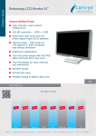
1
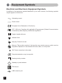
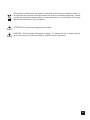
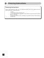
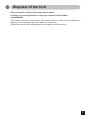
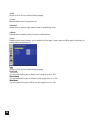
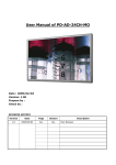
Display User's Manual
MD-DFM24-ENDO
24-inch (61.1cm) Color LCD Display
Conformity according to the Council Directive 93/42/EEC concerning Medical
Devices.
Use this product after carefully reading this Manual and understanding the
contents.
Store this manual with care, as close as possible, so that you can read
whenever necessary.
Thank you for purchasing our color LCD
Display.
◆Carefully read this User's Manual and use
the product properly. Before using it, also
read "Safety Precautions."
◆Keep the User's Manual as close to you as
possible and in safe custody.
◆If you have lost the manual, contact your
dealer. We will reissue a manual.
◆The names of companies and products are
registered brand names or brand names.
Contents
1. Safety Precautions
2. Equipment Symbols
3. Cleaning Instructions
4. Disposal of the Unit
5. Application and Function Description
6. Features
7. Connection Method
6. Adjustment Method
7. Reference
7. Compatible Signals
8. Specifications
9. Contact Information
1
4
6
7
8
9
10
12
36
37
38
40
Revision History
The revision letter changes with related comments each time the document is updated.
Revision
Comment
A
Initial release of this document
Safety Precautions
I CAUTION
Symbol Description
Caution!-This symbol alerts you to important operating
considerations or a potential operating condition that
could damage equipment. Refer to user's manual or
operation's manual for precautionary instructions.
II CLASSIFICATION
MEDICAL EQUIPMEN T
WITH RESPECT TO ELECTRIC SHOCK,
FIRE AND MECHANICAL HAZARD S ONLY IN
ACCORDANCE WITH UL60601-1 AN D
CAN/CSA C22.2 NO.601. 1
49CG
Class I :
No applied parts
Protection against harmful ingress of water is IPX5 for front.
Protection against harmful ingress of water is IPX2 for others.
Not suitable for use in the presence of flammable anesthetic's or oxygen.
Mode of operation: Continuous.
III External Equipment
External equipment intended for connection to signal input / output or other connectors, shall
comply with UL/EN 60601-1 for medical electrical equipment. In addition, all such combination
system shall comply with the standard IEC 60601-1-1, Safety requirements for medical electrical
systems. Equipment not complying with UL/EN/IEC 60601-1 shall be kept outside the patient
environment, as defined on the systems standard.
IV Intended Use
The intended use of the equipment is to display medical imaging data and endoscopy
applications.
It is not allowed to operate the equipment with power supplies other than the supplied ones..
Only this combination of display and power supply is approved for use in the medical
environment. The flat-panel display and the power supply must not be used outdoors or in areas
where an explosion hazard may occur.
CAUTION:
The VESA 100 adapter according to VESA standard is available on the rear cover for wall or
swivel-arm mounting. The user is responsible for correct installation of the display.
1
V FCC
FCC Information
FCC(U. S. Federal Communications Commission)
This equipment has been tested and found to comply with the limits for a Class B digital
device, pursuant to part 15 of the FCC Rules. These limits are designed to provide reasonable
protection against harmful interference in a residential installation. This equipment generates,
uses, and can radiate radio frequency energy, and if not installed and used in accordance with
the instructions, may cause harmful interference to radio communications. However, there is
no guarantee that interference will not occur in a particular installation. If this equipment does
cause unacceptable interference to radio or television reception, which can be determined by
turning the equipment off and on, the user is encouraged to try to correct the interference by one
or more of the following measures:
● Reorient or relocate the receiving antenna.
● Increase the separation between the equipment and receiver.
● Connect the equipment into an outlet on a circuit different from that to which the receiver
is connected.
● Consult your dealer or an experienced radio/TV technician for help.
FCC Warning:
To assure continued FCC compliance, the user must use a grounded power supply cord and
the provided shielded video interface cable with bonded ferrite cores. Also, any unauthorized
changes or modifications to this monitor would void the user's authority to operate this device.
VI Precautions
2
● Make sure to carefully read the Operating Manual prior to using the monitor in order to
properly use the monitor.
● Note that, excluding those cases where a responsibility for legal compensation is
recognized, the manufacturer shall bear absolutely no responsibility for damage to this
product by a customer or a third party that results from the ignoring of contents entered in
this Operating Manual and mistaken use.
● Follow the instructions below for safety use of the LCD Monitor.
- To avoid electric shock, do not attempt to remove any cover or touch the inside of the
monitor. Only a qualified service technician should open the monitor case.
- Do not insert metal objects or spill liquid into the LCD monitor through cabinet slots.
They may cause accident fire, electric shock or failure. If a foreign object inserted or water
penetrated, unplug the AC cable and have the monitor serviced.
- Do not cover or block the vent holes in the case.
- Disconnect the power plug from the AC outlet if you will not use it for an indefinite period of
time.
- Do not touch the screen directly with your fingers. You may damage the screen, and oil
from your skin is difficult to move.
- Do not apply pressure to the screen. The LCD is very delicate.
● If your LCD monitor uses an AC/DC Adapter: Only use the Adapter, which accompanied
with this device. Use of another AC/DC Adapter may cause a malfunction or danger.
● If your LCD monitor does not operate normally-in particular, if there are any unusual
sounds or smells coming from it-unplug the AC cable immediately and contact the
manufacturer, authorized or service center.
VII Environment
- Place the monitor on a flat and leveled surface.
- Place the monitor in a well-ventilated place.
- Keep the monitor away from:
overly hot, cold or humid places, places directly under sunlight, dusty surroundings,
equipment that generate strong magnetic fields.
3
Equipment Symbols
Electrical and Electronic Equipment Symbols
In addition to the equipment symbols described in your user's manual, the following symbols
may be appear on the monitor.
Alternating current.
Direct current.
European Union Declaration of Conformity.
FCC. USA only. Complies with applicable US government (Federal Communications
Commission) radio-frequency interference regulations.
Fragile. Handle with care.
Indicates front.
Keep dry. Protect from rain.
Mercury. This product consists of devices that may contain mercury, which must be
recycled or disposed of in accordance with local, state, or country laws.
ON. Power connection to the mains.
Recycled materials or may be recycled.
Stacking limit by number.
Standby or power indicator.
This way up.
USB connector port.
4
This symbol indicates that the waste of electrical and electronic equipment must not
be disposed as unsorted municipal waste and must be collected separately. Please
contact an authorized representative of the manufacturer for information concerning
the decommissioning of your equipment
ATTENTION: Consult accompanying documents.
DANGER - Shock Hazard. Dangerous voltage. To reduce the risk of electric shock,
do not remove cover. Refer servicing to qualified service personnel.
5
Cleaning Instructions
Cleaning Instructions
Using a spray applicator, apply any of the approved liquids from the list below and use a
soft lint free cloth to clean the screen.
1. Water
2. Windex Blue (glass surfaces only)
3. Clorox Bleach (Active Ingredient: 5.25% Sodium Hypochlorite-Off the Shelf)
Mix 10:1 with H2O
4. Sagrotan® (dilution 3:100, containing 75 mg tartaric acid per 100ml solution)
5. Mild Soap
6
Disposal of the Unit
●Do not dispose of this product with general wastes.
●Follow your local regulations or rules upon dispose of this product.
●Hg WARNING
This product consists of devices that may contain mercury, which must be recycled or
disposed of in accordance with local, state, or country laws.
(Within this product, the backlight lamps in the display contain mercury.)
7
Application and Function Description
●Some Basic Facts
The liquid-crystal display (LCD) monitor supports the most common resolutions from 640
x 480 (VGA) up to 1920 x 1200 (WUXGA) and presents sharp, low-radiation images.
With the OSD touch key on the bottom of the display leaves ample space on your desk
for other peripheral equipment.
An VESA 100 adapter according to VESA standard is available on the rearcover for wall
or swivel-arm mounting.
●Function Descripion
The medical flat-screen display is built into a slim and ergonomic housing. The monitor
displays 1.07 Billion colors with a resolution of 1920 x 1200 pixels.
The signal is equivalent to the analog and digital standard signals of your PC.
After connection of the signal the flat-screen display automatically adapts, as far as
possible, to the VGA signal and presents a stable and centered image. Additional display
parameters, such as brightness and contrast, can be adjusted via the on-screen menu.
The equipment supplied includes the signal cables, the power supply with power cord
and this user manual.
●Transport Damage
If the equipment has obviously been damage in transit, make a written report immediately
upon arrival of the goods and notify the shipping agent. The shipping agent must be
informed of hidden damage in transit in writing within 2 work days.
●Unpacking
Before unpacking the flat-screen display, prepare a suitable area for it’s set-up. Choose a
location where the display will not be frequently exposed to direct sunlight or other strong
sources of light. The light reflects on the display, dazzling you, and you will have problems
seeing the displayed information.
After unpacking the display, check whether the shipment is complete and all items are
intact:
MD-DFM24-ENDO
• User's Manual
• External power supply SNP-A159
• DVI cable
• VGA cable
• Power cord EU
8
If items are missing or damaged, contact your dealer immediately. Keep the packaging
material and the shipping carton for storage or shipment of the flat-screen display.
Explanation of Symbols Used On The Devices, Safety Information
Explanation of information and symbols on the monitor nameplate.
Illustration- Type Rate Label of the Display
Manufacturer:
Product Name:
Model No:
Power Rating
24Vdc 4.6A
Serial No.:
EN 60601-1
UL60601-1
CAN/CSA 22.2
Canvys – Visual Technology Solutions
A Division of Richardson Electronics GmbH
Raiffeisenstraße 5
D-78166 Donaueschingen
Tel.: +49 (0) 771 / 8300-0 Fax: +49 (0) 771 / 8300-80
MD-DFM24-ENDO
The medical grade flat-screen display must only be operated
with the power supply Skynet Electronic SNP-A159
Serial Number
The device fulfills the requirements of the medical standard
EN 60601-1 and cUL 60601-1 and CAN/CSA 22.2 No.601.1
The symbol indicates compliance with the medical standard
EN 60601-1 and cUL 60601
Consult User’s Manual!
Refer to the manual and observe the safety information and
instructions explaining how to put the monitor into service.
General Notes on Electrical Safety
Explanation of information and symbols on the monitor nameplate.
Connecting medical electrical equipment to other medical electrical devices and/or
other non medical electrical devices, be it for diagnostic or therapeutic purposes or for
monitoring, creates a medical electrical system. The standard EN 60601-1-1 and cUL
60601 describes the requirements for these systems.
These systems must be composed of devices that comply either with the standard EN
60601-1 and or cUL 60601 or with the applicable IEC / ISO standard (PCs, for instance,
must meet the requirements of the standard IEC 60950) or that are equipped with
additional safety features, such as a protective earth conductor, isolating transformer
or electrically isolated interface (e.g. optocoupler). This applies to devices of protection
class I or II It is not permitted to integrate protection class 0 devices in medical electrical
systems.
In the patient environment the following maximum enclosure leakage currents (current
flowing between two device enclosures or between the enclosure of a device and the
protective earth conductor are permitted for medical devices:
normal condition:
0.1 mA
single fault condition:
0.5 mA (e.g. protective earth conductor interrupted)
Before putting the system into service for the first time, a specialist is required to check
that these values are not exceeded. If the enclosure leakage current of a device or of the
system exceeds the limit values stated above, additional protective measures, such as
connection to protective earth conductor, isolating transformers or conductive castors,
must be implemented to correct this problem.
10
Safety Information
DANGER:
Explosion Hazard – The display including the power supply is not designed for
use in areas of medical locations where an explosion hazard may occur.
In appropriate usage of flammable anesthetics, skin cleansing agents and
disinfectants the medical Displays can be used risk less in surgical rooms and
intensive care units.
It is not permitted to operate the devices in the presence of flammable
substances (e.g. gas).
WARNING:
Personal Injury — Medical electrical devices may be connected to other
devices or to parts of systems only when it has been made certain that there is
no danger to the patient, the user, or the environment as a result.
In those instances where there is any element of doubt concerning the safety
of connected devices, the user must contact the manufacturers concerned or
other informed experts as to whether there is any possible danger to the patient,
the operator, or the environment as a result of the proposed combination of
devices.
Connecting medical electrical devices to other medical electrical devices and/
or other non-medical electrical devices creates a medical system which must
comply with the system standard
EN 60601-1-1 / cUL 60601. Before putting the system into service, a specialist
is required to ascertain its conformity with the system standard.
WARNING:
Personal Injury — Before putting the device into service, check all cables for
signs of damage. Damaged cables must be replaced immediately with the
original manufacturer’s cables. The safety information and certificates do not
apply when cables from other manufacturers are used.
Do not open the flat-screen display or perform any service interventions. This
may render your warranty claims null and void. Only authorized technicians are
permitted to service the flat-screen display.
Do not put the flat-screen display into service
- when liquids have entered the device,
- when it was dropped and the housing is damaged.
Do not immerse the devices into liquids.
- Disconnect the power supply from the power line before cleaning. Use a moist
cloth.
11
WARNING:
Equipment Failure — Magnetic and electrical fields are capable of interfering
with the proper performance of the devices. For this reason make sure that all
devices operated in the vicinity comply with the relevant EMC requirements.
X-ray equipment, MRI devices, radio systems, and cellular telephones
are possible sources of interference as they may emit higher levels of
electromagnetic radiation.
Keep the system away from these devices and verify its performance before
use.
WARNING:
Risk of Suffocation — Dispose of the packaging material, observing the
applicable waste-control regulations and keeping it out of children's reach.
CAUTION:
Personal Injury — All devices used must comply with the applicable IEC/EN or
ISO standard (PCs, for instance, must comply with IEC 60950). This applies to
custom designs in particular.
During operation from flat-screen display (contact to monitor) do not
simultaneous touch patient.
CAUTION:
Personal Injury, Equipment Damage — Check that the ambient conditions
specified by the manufacturers of the different devices are ensured.
Before cleaning the flat-screen display, turn it off and remove power cord from
power supply. Do not spray liquid cleaning agents directly onto the display.
Spray the cleaning agent onto a cloth and wipe the display clean without
exerting any pressure.
Do not place any objects on the signal cables. Route the signal cables and the
power cable to the flat-screen display such that they do not present a stumbling
hazard.
CAUTION:
Equipment Damage — Do not set up the flat-screen display in the immediate
vicinity of a window. Rain, water, humidity and sunlight may damage the flatscreen display.
Do not exert pressure on the LCD. Excessive pressure may permanently
damage the display.
For safe storage of the flat-screen display, a temperature between -20°C
and +60°C must be ensured. Temperatures above or below this range may
permanently damage the flat-screen display. Always store your flat-screen
display in its original shipping box.
12
EC declaration of conformance:
EC Declaration of Conformity
Manufacturer
Richardson Electronics GmbH
Division Canvys
Raiffeisenstraße 5
D-78166 Donaueschingen
Product:
Medical Monitor (product group 1)
MD-DFM24-ENDO
Classification:
(Directive 93/42/EWG)
Tel.: +49 (0) 771 / 8300-0
Fax: +49 (0) 771 / 8300-80
I
We declare in own responsibility, that the above named products correspond to relevant
regulations according to the following EG guidelines and standards.
Directive:
Directive 93/42/EWG of the Council of 14. Jun. 1993
Standards:
DIN EN 13485: 2003 + AC2007
Medical Products-Quality management system
IEC 60601-1 3rd Edition: 2005 = EN 60601-1:2007
General Requirements Of Basic Safety and Essential Performance
EN 60601-1-2: 2007
EMC-Directive
EMC – Emission
EMC – Immunity
EMC-Tests have been carried out using standard cables with cables length of up to
2,5 meters. If longer cables are used, additional tests might be necessary to prove
compliance with the EMC-directive.
Conformity assessment procedure:
Annex VII
Name:
Position:
Bernhard Zimmermann
Director of European Sales
13
Features
●24-inch LCD display with 2.3 million pixels
This color LCD display has a multi-scanning function corresponding to the resolution
from VGA 640 x 400 to WUXGA 1920 x 1200. This is also compliant with VESA standard
display mode.
●High-intensity, high-contrast
Beautiful and clear images of the brightness of 400 cd/m2 and contrast ratio of 1000:1
have been achieved. Viewing angles are the wide range of 178 degrees in both
horizontal and vertical directions (CR>=10). The unit has installed our unique automatic
brightness stabilizing circuit that restrains deteriorations and brightness drifts when power
is turned on. Gamma curve adjustments are made by OSD. This is for various modality
terminals, medical image displays for PACS*1, and graphics.
●Remote control port
This color LCD display has the remote control port that controls the functions of the
monitor.
●Power management
This unit has loaded the power management system. The power management mode
functions when either horizontal or vertical signals or both disappears, and it reduces
power consumption to less than 16W.
●VESA® standard wall / arm mountings
The unit is compliant with VESA's hanging tools. The tilt stand is detachable; the unit can
be set for wall-hanging or arm according to users' environment.
Note 1) PACS: Picture Archive & Communication System
14
Connection Method
1. Confirm that your computer is off. Then, confirm that the main switch of the color LCD monitor
is off.
Caution
●Disconnect Device-The following component is considered the equipment disconnect
device "AC Power Inlet"
●Make sure you use the auxiliary AC Adapter.:
Type SNP-A159.
2. Connect the signal cable (for PC input)
Connect the VGA connector of the monitor and the analog RGB output connector with the
attached VGA cable.
Connect the DVI connector of the monitor and the digital RGB output connector with the
attached DVI cable (24-pin DVI).
15
3.Connect Video signal Cable (for video device output)
Connect S-Video connector of the LCD monitor and an S-Video output device with the
attached S-Video cable. For composite signal connect the BNC connector of the monitor and a
composite video output device with the composite video cable.
4.Connect component Video connector of the LCD monitor and a component Video output
device with the component video cable.
16
Adjustment Method
Names and Functions of Each Part
① Touch key
Power ON/OFF
・Pressing “Power” key turns on the LCD display.
・Pressing “Power” key for more than three seconds turns the power off.
OSD control
・When “Menu” key is pressed while images are on screen, OSD* will appear on screen.
*OSD stands for on-screen-display. Its function is to display information such as characters
and symbols.
・Execution of selected items and display of submenus can be
performed while OSD is on screen.
Press “Enter” key: execute/ select items/ save data
Source select
・Pressing “Source” key (VGA,DVI,HDMI...) changes the present source.
② POWER indicator (Power/ Power management display)
・The indicator illuminates green when power normally on.
・The indicator illuminates orange and the display turns off when power management function
on or no signals.
・The indicator goes out when power off.
③ DC power input connector
This is connected to a DC power connector from the provided AC power adapter.
④ CVBS Video input/output connector
Composite signal input. The attached composite video connection cable is connected to
this and a video output device.
17
⑤ Component/RGBS input/output connector
When using component input to watch a DVD, HD (High Definition) or RGBS video image,
The attached component video connector cable is connected to this and a component output
video device.
⑥ S-Video input/output connector
S-Video signal input. The attached S-Video signal cable is connected to this and an S-Video
output video device.
⑦ Analog input connector VGA
Analog video signal input. The analog signal cable is plugged into this.
⑧ Digital input connector DVI
Digital video signal input. The provided digital signal cable is plugged into this. This is available
to a computer with a DVI digital video output.
⑨ Digital input connector HDMI
Digital video signal input. The provided digital signal cable is plugged into this. This is available
to a computer with a HDMI digital video output.
⑩ Control input connector GPIO DIN-9
⑪ Calibration connector USB
Connect with PC to calibrate Gamma curve.
⑫ HD/SD SDI input/output connector
Connect SDI in connector of the LCD monitor and a SDI out device (camcoder, DVD...etc.)with
75-Ohm coaxial cable.
18
Mounting
The Monitor can be mounted onto the wall or stand.
If you intend to mount the monitor on the wall, we strongly recommend that you use wall mount
kits with attached M4*10mm screws and can load more than monitor weight, that you ensure it
is securely and safely installed.
CAUTION:
When mounting the monitor, take care to tighten the retention screws or bolts until fully secure,
but do not over tighten. Over tightening the retention screws or bolts may cause them to become
stripped, rendering them useless.
Wall Mounting Installation
100.0
200.0
100.0
The Monitor has Video Electronics Standards Association (VESA) standard mounting holes
tapped into the rear panel. The standard holes are M4 set at 100 mm x 100 mm or 200mm x
100mm apart.
To mount the Monitor onto the wall or stand, please follow the steps below.
Step 1: Select the location on the wall for the wall-mounting bracket.(Listed VESA)
Step 2: Carefully mark the locations of the four screw holes in the bracket on the wall
Step 3: Drill four pilot holes at the marked locations on the wall for the bracket retention screws.
Step 4: Align the wall-mounting bracket screw holes with the pilot holes.
Step 5: Secure the mounting-bracket to the wall by inserting the retention screws into the four
pilot holes and tightening them.
Step 6: Insert the four monitor mounting screws provided in the wall mounting kit into the four
screw holes on the real panel of the LCD Monitor and tighten until the screw shank is secured
against the rear panel.
Step 7: Align the mounting screws on the monitor rear panel with the mounting holes on the
bracket.
Step 8: Carefully insert the screws through the holes and gently pull the monitor downwards
until the monitor rests securely in the slotted holes. Ensure that all four of the mounting screws
fit snuggly into their respective slotted holes.
Step 9: Secure the LCD Monitor by fastening the retention screw of the wall-mounting bracket.
Step 10: Secure the LCD Monitor by fastening the retention screw of the wall-mounting bracket. 19
Charts of OSD Adjustment Functions
The charts displays the function tree and brief explanations of the functions.Color,LCD,and other
adjustments have submenus under each tree.
● OSD display
Main menu display
• Exit• • • • • • • • • • • • • • • • • • • • • • • • • • • • • • • • • • • • • • • • • • • • • • • • • • • • •
• Input Source Settings
Exit• • • • • • • • • • • • • • • • • • • • • • • • • • • • • • • • • • • • • • • • • •
Analog VGA• • • • • • • • • • • • • • • • • • • • • • • • • • • • •
Digital• • • • • • • • • • • • • • • • • • • • • • • • • • • • • • • • • • • • • • •
HDMI• • • • • • • • • • • • • • • • • • • • • • • • • • • • • • • • • • • • • • •
S-Video• • • • • • • • • • • • • • • • • • • • • • • • • • • • • • • • • • • •
CVBS• • • • • • • • • • • • • • • • • • • • • • • • • • • • • • • • • • • • • • •
YPbPr/YCbCr• • • • • • • • • • • • • • • • • • • • • • • • • •
RGBS• • • • • • • • • • • • • • • • • • • • • • • • • • • • • • • • • • • • • •
SDI• • • • • • • • • • • • • • • • • • • • • • • • • • • • • • • • • • • • • • • • • • •
• Image Settings
Exit• • • • • • • • • • • • • • • • • • • • • • • • • • • • • • • • • • • • • • • • • • •
Auto Setup
Black Level• • • • • • • • • • • • • • • • • • • • • • • • • • • • • •
Contrast• • • • • • • • • • • • • • • • • • • • • • • • • • • • • • • • • • •
Saturation• • • • • • • • • • • • • • • • • • • • • • • • • • • • • • • •
Hue• • • • • • • • • • • • • • • • • • • • • • • • • • • • • • • • • • • • • • • • • •
Sharpness• • • • • • • • • • • • • • • • • • • • • • • • • • • • • • •
Display
Exit• • • • • • • • • • • • • • • • • • • • • • • • • • • • •
H.Position• • • • • • • • • • • • • • • • • • •
V.Position• • • • • • • • • • • • • • • • • • •
Clock• • • • • • • • • • • • • • • • • • • • • • • • • •
Phase• • • • • • • • • • • • • • • • • • • • • • • • •
• Color Mode Settings
Exit• • • • • • • • • • • • • • • • • • • • • • • • • • • • • • • • • • • • • • • • • •
Color Temp.
Exit• • • • • • • • • • • • • • • • • • • • • • • • • • • • •
Cool• • • • • • • • • • • • • • • • • • • • • • • • • • • •
Neutral• • • • • • • • • • • • • • • • • • • • • • • •
Warm• • • • • • • • • • • • • • • • • • • • • • • • • •
User
Exit• • • • • • • • • • • • • • • •
Red Gain• • • • • • •
Green Gain• • • •
Blue Gain• • • • • • •
Gamma
Exit• • • • • • • • • • • • • • • • • • • • • • • • • • • • •
Gamma 1.8• • • • • • • • • • • • • • • • •
Gamma 2.0• • • • • • • • • • • • • • • • •
Gamma 2.2• • • • • • • • • • • • • • • • •
Gamma 2.4• • • • • • • • • • • • • • • • •
Calibration• • • • • • • • • • • • • • • • • •
DICOM• • • • • • • • • • • • • • • • • • • • • • •
•••••••••••••••••••••••••••••••
20
Close the OSD screen
Return to Main Menu
Select Analog video input for Main channel
Select DVI digital video input for Main channel
Select HDMI digital video input for Main channel
Select S-video video input for Main channel
Select Composite video input for Main channel
Select Component video input for Main channel
Select R, G, B, Xs-sync video input for Main channel
Select SDI video input for Main channel
Return to Main Menu
Automatic screen size/position/brightness/contrast adjustment
Adjust the black level offset for the Main channel by the range from 0 to 100
Adjust the contrast for the Main channel by the range from 0 to 100
Adjust the saturation for the Main channel by the range from 0 to 100
Adjust the hue for the Main channel by the range from 0 to 100
Adjust the sharpness for the Main channel by the range from 0 to 24
Return to Exit of Image Setting page
Adjust horizontal screen position for Main channel
Adjust vertical screen position for Main channel
Adjust the clock for the video signals for Main channel
Adjust the phase for the video signals for Main channel
Return to Main Menu
Return to Exit of Color Mode Settings page
Blueish white used for general use
White close to natural light mainly used for publishing trade
Redish white suitable mainly for photo modifications
Return to Exit of Color Temp. of Color Mode Settings page
User adjusts the gain of Red by the range from 0 to 100
User adjusts the gain of Green by the range from 0 to 100
User adjusts the gain of Blue by the range from 0 to 100
Return to Exit of Color Mode Settings page
Set Gamma curve to curve 1.8
Set Gamma curve to curve 2.0
Set Gamma curve to curve 2.2
Set Gamma curve to curve 2.4
Calibrate monitor setting by using external device
Set Gamma curve to DICOM curve
• Multi-PIP Settings
Exit• • • • • • • • • • • • • • • • • • • • • • • • • • • • • • • • • • • • • • • • • •
PIP mode• • • • • • • • • • • • • • • • • • • • • • • • • • • • • • • •
PIP Source
Exit• • • • • • • • • • • • • • • • • • • • • • • • • • • • •
Analog VGA• • • • • • • • • • • • • • • •
Digital• • • • • • • • • • • • • • • • • • • • • • • • •
HDMI• • • • • • • • • • • • • • • • • • • • • • • • • •
S-Video• • • • • • • • • • • • • • • • • • • • • • •
CVBS• • • • • • • • • • • • • • • • • • • • • • • • • •
YPbPr/YCbCr• • • • • • • • • • • • •
RGBS• • • • • • • • • • • • • • • • • • • • • • • • •
SDI• • • • • • • • • • • • • • • • • • • • • • • • • • • • •
PIP Display
Exit• • • • • • • • • • • • • • • • • • • • • • • • • • • • •
PIP Size
Exit• • • • • • • • • • • • • • • • • • • • • •
PIP Size• • • • • • • • • • • • • •
PIP H-Size• • • • • • • • • •
PIP V-Size• • • • • • • • • • •
PIP Position
Exit• • • • • • • • • • • • • • • • • • • • • •
PIP H. Position• • • •
PIP V. Position• • • •
Swap• • • • • • • • • • • • • • • • • • • • • • • • • • • • • • • • • • • • • • • •
PIP Picture
Exit• • • • • • • • • • • • • • • • • • • • • • • • • • • • •
Black Level• • • • • • • • • • • • • • • • •
Contrast• • • • • • • • • • • • • • • • • • • • • •
Saturation• • • • • • • • • • • • • • • • • • •
Hue• • • • • • • • • • • • • • • • • • • • • • • • • • • • •
Sharpness• • • • • • • • • • • • • • • • • •
• Management Settings
Exit• • • • • • • • • • • • • • • • • • • • • • • • • • • • • • • • • • • • • • • • • • •
Return to Main Menu
Select PIP mode to Off or PIP or POP
Return to Exit of Multi-PIP Settings page
Select Analog video input for Sub channel
Select DVI digital video input for Sub channel
Select HDMI digital video input for Sub channel
Select S-video video input for Sub channel
Select Composite video input for Sub channel
Select Component video input for Sub channel
Select R, G, B, Xs-sync video input for Sub channel
Select SDI video input for Sub channel
Return to Exit of Multi-PIP Settings page
Return to Exit of PIP Display of Multi-PIP Settings page
Adjust the full size for Sub channel display
Adjust the H size for Sub channel display
Adjust the V size for Sub channel display
Return to Exit of PIP Display of Multi-PIP Settings page
Adjust the H position for Sub channel display by the range from 0 to 100
Adjust the V position for Sub channel display by the range from 0 to 100
Swap source between Main and Sub channel
Return to Exit of Multi-PIP Settings page
Adjust the black level offset for the Sub channel by the range from 0 to 100
Adjust the contrast for the Sub channel by the range from 0 to 100
Adjust the saturation for the Sub channel by the range from 0 to 100
Adjust the hue for the Sub channel by the range from 0 to 100
Adjust the sharpness for the Sub channel by the range from 0 to 24
Return to Main Menu
Scaling
Exit• • • • • • • • • • • • • • • • • • • • • • • • • • • • • Return to Exit of Management Settings page
Scaling• • • • • • • • • • • • • • • • • • • • • • • • Support Full & Native Mode & Best Fit &Fit Width &Fit Height & Over
Screen 6 modes
Zoom• • • • • • • • • • • • • • • • • • • • • • • • • • Adjust the full size for Main channel display(Must under Full scaling mode)
Her. Zoom• • • • • • • • • • • • • • • • • • • Adjust the H size for Main channel display (Must under Full scaling mode)
Ver. Zoom• • • • • • • • • • • • • • • • • • • Adjust the V size for Main channel display (Must under Full scaling mode)
Recall• • • • • • • • • • • • • • • • • • • • • • • • • • • • • • • • • • • • • • • Initialize to the factory settings and delete the specify User setting you
saved
•
•
•
•
•
•
•
•
•
•
•
•
•
•
•
•
•
•
•
•
•
•
On/off ‘’Auto Adjustment’’ Function
Auto Adjustment
•
•
•
•
•
•
•
•
•
•
•
•
•
•
•
•
•
•
•
•
•
•
•
•
•
•
•
If turn on will make full screen without color
Monochrome
ALS• • • • • • • • • • • • • • • • • • • • • • • • • • • • • • • • • • • • • • • • • • On/off ‘’Auto Luminance System ’’ Function
21
New Timing Search
Exit• • • • • • • • • • • • • • • • • • • • • • • • • • • • •
Execute• • • • • • • • • • • • • • • • • • • • • •
Aspect• • • • • • • • • • • • • • • • • • • • • • • •
1:1• • • • • • • • • • • • • • • • •
2:1• • • • • • • • • • • • • • • • •
4:3• • • • • • • • • • • • • • • • •
5:4• • • • • • • • • • • • • • • • •
16:9• • • • • • • • • • • • • • •
16:10• • • • • • • • • • • • •
Clock• • • • • • • • • • • • • • • • • • • • • • • • • •
H.Position• • • • • • • • • • • • • • • • • • •
V.postion• • • • • • • • • • • • • • • • • • • • •
H size• • • • • • • • • • • • • • • • • • • • • • • • • •
V size• • • • • • • • • • • • • • • • • • • • • • • • • •
Save Timing• • • • • • • • • • • • • • • •
HDMI Video Format• • • • • • • • • • • • • • • • •
Auto Source• • • • • • • • • • • • • • • • • • • • • • • • • • • • •
LED Drive• • • • • • • • • • • • • • • • • • • • • • • • • • • • • • • •
• OSD Misc.
Exit• • • • • • • • • • • • • • • • • • • • • • • • • • • • • • • • • • • • • • • • • • •
OSD Position
Exit• • • • • • • • • • • • • • • • • • • • • • • • • • • • •
OSD H.Position• • • • • • • • • •
OSD V.Position• • • • • • • • • • •
Language
Exit• • • • • • • • • • • • • • • • • • • • • • • • • • • • •
English• • • • • • • • • • • • • • • • • • • • • • • •
Francais• • • • • • • • • • • • • • • • • • • • • •
Deutsch• • • • • • • • • • • • • • • • • • • • • •
Italiano• • • • • • • • • • • • • • • • • • • • • • • •
Espanol• • • • • • • • • • • • • • • • • • • • • •
日本語• • • • • • • • • • • • • • • • • • • • • • • • •
Preset Save
Exit• • • • • • • • • • • • • • • • • • • • • • • • • • • • •
Save
Exit• • • • • • • • • • • • • • • •
User 1• • • • • • • • • • • •
User 2• • • • • • • • • • • •
User 3• • • • • • • • • • • •
User 4• • • • • • • • • • • •
User 5• • • • • • • • • • • •
22
Return to Exit of Management Settings page
Execute New Timing Search that wasn’t in the preset timing table
Adjust the Aspect for the video signals for Main channel
Executing the new timing search according to 1:1 aspect
Executing the new timing search according to 2:1 aspect
Executing the new timing search according to 4:3 aspect
Executing the new timing search according to 5:4 aspect
Executing the new timing search according to 16:9 aspect
Executing the new timing search according to 16:10 aspect
Adjust the clock for the video signals for Main channel (active after press
Execute)
Adjust horizontal screen position for Main channel (active after press
Execute)
Adjust vertical screen position for Main channel(active after press Execute)
Adjust the H size for Main channel display (active after press Execute)
Adjust the V size for Main channel display(active after press Execute)
There are Save & Clear for New Timing Setting
Provide HDMI source color space format select
Automatically select the signal source.
Adjust the brightness for the indicator LED by the range from 0 to 100
Return to Main Menu
Return to Exit of OSD Misc.
Adjust the H position for OSD by the range from 0 to 100
Adjust the V position for OSD by the range from 0 to 100
Return to Exit of OSD Misc
Display OSD in English
Display OSD in French
Display OSD in German
Display OSD in Italian
Display OSD in Spanish
Display OSD in Japanese
Return to Exit of OSD Misc.
Return to Exit of Preset Save of OSD Misc.
Save all adjust settings to User1
Save all adjust settings to User2
Save all adjust settings to User3
Save all adjust settings to User4
Save all adjust settings to User5
Load
Exit• • • • • • • • • • • • • • • • Return to Exit of Preset Save of OSD Misc.
User 1• • • • • • • • • • • • Load all adjust settings from User1
User 2• • • • • • • • • • • • Load all adjust settings from User2
User 3• • • • • • • • • • • • Load all adjust settings from User3
User 4• • • • • • • • • • • • Load all adjust settings from User4
User 5• • • • • • • • • • • • Load all adjust settings from User5
•
•
•
•
•
•
•
•
•
• • • • • • • • • • • • • • • • • • • • • Adjust OSD display time
OSD Timer
Transparent• • • • • • • • • • • • • • • • • • • • • • • • • • • • • Adjust OSD display transparent
23
Charts of OSD Adjustment Functions
The charts displays the function tree and brief explanations of the functions. Color, LCD, and
other adjustments have submenus under each tree.
Detail of Adjustment Items
Exit
Close the Main Menu.
In addition, this page will show below messages:
(1)Information for input timing of Main channel .
(2)Timing table provide by system.
(3)Indicate which source display for Main channel.
(4)Indicate which source display for Sub channel.
(5)Record how long time display for this monitor already.
Input Source Setting
You can select source for Main channel from Analog VGA, Digital, HDMI, S-video, CVBS,
YPbPr/ PCbCr, RGBS ,SDI.
24
Image Settings
Adjust values of below items for Main channel. Beside VideoSetup that only support on S-video
& CVBS & YPbPr/PCbCr & RGBS & SDI.
* Notice: VideoSetup will be disable under Analog VGA or Digital or HDMI source.
Exit
Return to Main Menu.
Auto Setup
When you press ‘’Auto Setup’’ will show ‘’Auto Adjusting’’ on the screen that do automatically
adjust the size, position, brightness, contrast and the like of the screen. When first using this
color display or input new timing will perform this adjustment. When ‘’Auto Adjusting’’ disappear
from the screen means it have finished the ‘’Auto Setup’’ function.
Black Level
Adjust the black level offset for the Main channel by the range from 0 to 100.
Black Level
50
Contrast
Adjust the contrast for the Main channel by the range from 0 to 100.
25
Saturation
Adjust the saturation for the Main channel by the range from 0 to 100.
Hue
Adjust the hue for the Main channel by the range from 0 to 100.
Sharpness
Adjust the sharpness for the Main channel by the range from 0 to 24.
Sharpness
12
Display
Adjust the Horizontal & Vertical position & clock & phase for Main channel.
• Exit
Return to Exit of Image Setting page.
• H.Position
Adjust horizontal screen position for Main channel by the range from 0 to 100.
• V.Position
Adjust vertical screen position for Main channel by the range from 0 to 100.
26
• Clock
Adjust the frequency sampling rate of horizontal pixels for Main channel, to equal the video
source’s value,Thus minimizing artifacts of shimmering vertical lines.
* Notice: Only support on Analog VGA source.
• Phase
Adjust ADC sampling clock phase for Main channel, so that the screen image appear crisp and
focused.
* Notice: Only support on Analog VGA source.
Color Mode Settings
Selecting this control allows you select color temperature or gamma curve.
Exit
Return to Main Menu.
Color Temp.
Selecting this control allows you to select preset color temperature of Cool, Neutral, Warm, or
User for customized red, green and blue levels.
27
• Exit
Return to Exit of Color Mode Settings page.
• Cool
Blueish white used for general use.
• Neurtal
White close to natural light mainly used for publishing trade.
• Warm
Redish white suitable mainly for photo modifications.
• User
Selecting this control allows you to adjust the Red gain, Green gain and Blue gain individually to
match personal preference.
Exit
Return to Exit of Color Mode Settings page.
Red Gain
You can adjusts the gain of Red by the range from 0 to 100.
Green Gain
You can adjusts the gain of Green by the range from 0 to 100.
Blue Gain
You can adjusts the gain of Blue by the range from 0 to 100.
28
Gamma
Selecting this control allows you to choose which gamma curve that you want.
• Exit
Return to Exit of Color Mode Settings page.
• Gamma 1.8
Set Gamma curve to curve 1.8
• Gamma 2.0
Set Gamma curve to curve 2.0
• Gamma 2.2
Set Gamma curve to curve 2.2
• Gamma 2.4
Set Gamma curve to curve 2.4
• Calibration
Set Gamma curve to calibration mode.
• DICOM
Set Gamma curve for medical standards.
29
Multi-PIP Settings
Selecting this control allows you to adjust below items settings for Sub channel.
* Notice: PIP Display & Swap & PIP Picture only active when PIP Mode set to PIP or POP.
Exit
Return to Main Menu.
PIP mode
Select PIP mode to Off mode or PIP mode or POP mode as below:
PIP source
You can select source for Sub channel from Analog VGA, Digital, HDMI, S-video, CVBS, YPbPr/
PCbCr, RGBS (Gray area are not available to choose).
Please find the below matrix to see the combinations for Main channel with Sub channel if you
set to PIP mode or POP mode.
Main
channel
VGA
DVI
HDMI
S-video
CVBS
YPbPr
RGBS
SDI
30
VGA
X
O
O
O
O
O
X
O
DVI
O
X
X
O
O
O
O
O
Sub channel
HDMI S-video CVBS
O
O
O
X
O
O
X
O
O
O
X
O
O
O
X
O
O
O
O
O
O
O
O
O
YPbPr
O
O
O
O
O
X
X
O
RGBS
X
O
O
O
O
X
X
O
SDI
O
O
O
O
O
O
O
X
PIP Display
Selecting this control allows you to adjust the size and position for Sub channel.
• Exit
Return to Exit of Multi-PIP Settings page.
• PIP Size
Selecting this control allows you to adjust the size for Sub channel.
Exit
Return to Exit of PIP Display of Multi-PIP Settings page.
PIP Size
Adjust the H size for Sub channel display.
PIP H Size
Adjust the V size for Sub channel display.
• PIP Position
Selecting this control allows you to adjust the position for Sub channel.
Exit
Return to Exit of PIP Display of Multi-PIP Settings page.
PIP H.Position
Adjust the H position for Sub channel display by the range from 0 to 100.
PIP V.Position
Adjust the V position for Sub channel display by the range from 0 to 100.
Swap
Swap source between Main and Sub channel.
31
PIP Picture
Selecting this control allows you to adjust the below items settings for Sub channel.
• Exit
Return to Exit of Multi-PIP Settings page.
• Black Level
Adjust the black level offset for the Sub channel by the range from 0 to 100.
• Contrast
Adjust the contrast for the Sub channel by the range from 0 to 100.
• Saturation
Adjust the saturation for the Sub channel by the range from 0 to 100.
• Hue
Adjust the hue for the Sub channel by the range from 0 to 100.
• Sharpness
Adjust the sharpness for the Sub channel by the range from 0 to 24.
* Notice: Only support Sub channel was S-video or CVBS or YPbPr/ PCbCr & or RGBS.
Management Settings
Selecting this control allows you to adjust below items settings for Main channel.
32
Exit
Return to Main Menu.
Scaling
Selecting this control allows you to adjust below items relate to image scaling for Main channel.
• Exit
Return to Exit of Management Settings page.
• Scaling
Support Full & Native Mode & Best Fit & Fit Width & Fit Height & Over Screen 6 modes.
• Zoom
Adjust the full size for Main channel display.
* Notice: Support Zoom must under Full scaling mode for each source.
• Her.Zoom
Adjust the H size for Main channel display.
* Notice: Support Her. Zoom must under Full scaling mode for each source.
• Ver.Zoom
Adjust the V size for Main channel display.
* Notice: Support Ver. Zoom must under Full scaling mode for each source.
Recall
Select this function to recall all OSD adjustments to the factory default settings and delete the
specify User setting you used.
Ex: If you load User1 from Preset Save page, the system will clear User 1 after you press ‘’recall’’
Auto Adjustment
Select this function to on or off ‘’Auto Adjustment’’ Function.
Monochrome
Select this function to ‘’on’’ will make full screen without color.
33
New Timing Search
This function will auto calculate image according to the input timing data if it wasn’t in the preset
timing table and as far as possible to display the image that close to the input new timing.
Display a dot on-dot off test pattern or full screen test pattern and press ‘’Execute’’ to get certain
display image.
If new timing search is not still available or does not give satisfactory results, proceed as follows:
1. Entry into ‘’Management Settings’’ page to adjust clock/ H.position.
2. Adjust the image width fits the LCD panel width.
3. Then, press the ‘’Execute’’, use this function to search new timing again.
4. Save the several timings which have been fine tune successfully. (Refer to the details on
page 30 ‘’Save Timing’’ section)
* Notice: This function only support on Analog VGA and RGBS source without PIP or POP
function.
• Exit
Return to Exit of Management Settings page.
• Execute
Execute New Timing Search that wasn’t in the preset timing table.
• Aspect
Adjust the display ratio of the video signals for Main channel. (active after press Execute; default
was disable this function)
• Clock
Adjust the clock for the video signals for Main channel. (active after press Execute; default was
disable this function)
• H.Position
Adjust horizontal screen position for Main channel. (active after press Execute; default was
disable this function)
• V.Position
Adjust vertical screen position for Main channel. (active after press Execute; default was disable
this function)
34
• Save Timing
There are Save & Clear for New Timing Setting.
If the user makes any additional adjustment, the video signal (with its adjustments) can be
stored as user mode.
The next time this video signal is connected and selected , the display recognizes it as one of
the user modes and reproduces it with the corresponding adjustments. The signal is recognized
by its timing and the type of video input it is connected to. This means a certain video signal
connected to the VGA or RGBS(BNC) can be stored as two different user modes.
The display memory can contain maximum 16 different users modes (VGA and RGBS source
can store separately)
When the memory is full, user can use ‘’clear timing’’ to clear some of the 16 modes when a new
video signal is adjusted.
You can save the new timing after you press Execute, totally can save sixteen timings.
1. Choose save and entry into ‘’Save timing’’ page.
2. Move to blank place then press enter you will see below photo and select ‘’Yes’’ to enter.
Correct save timing data?
No
Yes
3. You will see the new timing have stored in the system and show on the ‘’Save timing’’ page.
35
You also can clear the new timing after you save.
1. Choose clear and entry into the ‘’Clear timing’’ page.
2. Move to the timing that you want to clear then press enter you will see below photo and select
‘’Yes’’ to enter.
Correct clear timing data?
No
Yes
3. You will see the new timing have cleared from the ‘’Clear timing’’ page.
HDMI Video Format
Provide HDMI video format select for HDMI source for Main and Sub channel both.
There are auto & YCbCr4:4:4 & YCbCr4:2:2 & RGB 4 models.
Default is set to ‘’Auto’’ that monitor auto detect input color space.
If monitor show wrong color under HDMI source, you can manual select color space to
YCbCr4:4:4(4:2:2) or RGB .
Auto Source
Automatically select the signal source.
LED Drive
Adjust the brightness for the indicaror LED by the range from 0 to 100.
36
OSD Misc.
Selecting this control allows you to adjust below items settings for OSD.
Exit
Return to Main Menu.
OSD Position
Selecting this control allows you to adjust position for OSD.
• Exit
Return to Exit of OSD Misc.
• OSD H.Position
Adjust the H position for OSD by the range from 0 to 100.
• OSD V.Position
Adjust the V position for OSD by the range from 0 to 100.
37
Language
Selecting this control allows you to choose below languages that you want to display for OSD.
• Exit
Return to Exit of OSD Misc.
• English
Display OSD in English.
• Francais
Display OSD in French.
• Deutsch
Display OSD in German.
• Italiano
Display OSD in Italian.
• Espanol
Display OSD in Spanish.
• 日本語
Display OSD in Japanese.
38
Preset Save
Selecting this control allows you to save OSD setting after you adjust into five User settings
separately. You also can load any one of five user settings for the OSD setting that you adjust
then save into five User settings.
• Exit
Return to Exit of OSD Misc.
• Save
Save OSD setting after you adjust into five User settings separately.
Exit
Return to Exit of Preset Save of OSD Misc.
User 1
Save all adjust settings to User 1.
User 2
Save all adjust settings to User 2.
User 3
Save all adjust settings to User 3.
User 4
Save all adjust settings to User 4.
User 5
Save all adjust settings to User 5.
39
• Load
Load any one of five user settings for the OSD setting that you adjust then save into five User
settings.
Exit
Return to Exit of Preset Save of OSD Misc.
User 1
Load all adjust settings to User 1.
User 2
Load all adjust settings to User 2.
User 3
Load all adjust settings to User 3.
User 4
Load all adjust settings to User 4.
User 5
Load all adjust settings to User 5.
OSD Timer
Adjust OSD display time that support 5 & 10 & 15 & 20 & 25 & 30.
OSD will not disappear if set to 0.
OSD will disappear after 5 sec if set to 5 (just like that for 10 & 15 & 20 & 25 & 30).
Transparent
Adjust OSD display transparent from 0 to 7 by one step.
40
Reference
DDC*1
◆ This unit has loaded a function compliant with DDC-2B, VESA* standard.
The DDC function is located in 15-pin D-sub connector and 24-pin DVI-D connector.
This function reads into the set data written in the color LCD display internal device in
advance on start-up of Windows®/98/Me/2000 or Windows®XP and sets the detailed
information of the color LCD display in the system file in order to achieve Plug & Play.
Data reading from the color LCD display is done through a video signal cable, which
needs to be connected when Windows®95/98/Me/2000 or Windows®XP is on.
Note
*1DDC (Display Data channel) and*2 VESA are registered trademarks of Video
Electronics Standards Association.
41
Compatible Signals
Applicable Signals Timings
※The display may not work correctly with timings other than listed below.
◎ : Recommended timing
Mode Name
VGA
SVGA
XGA
SXGA
UXGA
WUXGA
720 X 400
1024 X 940
1024 X 1024
Mac
576/50i (PAL)
480/60i (NTSC)
576/50P
480/60P
720/50p
720/60p
1080/50i
1080/60i
1080/50p
1080/60p
42
○ : Applied timing
Resolution
Frequency
Input Signal Input Signal
H
V
H(kHz)
V(Hz)
Analog
Digital
640
640
640
640
800
800
800
800
800
1024
1024
1024
1024
1280
1280
1600
1920
720
1024
1024
640
832
1024
480
480
480
480
600
600
600
600
600
768
768
768
768
1024
1024
1200
1200
400
940
1024
480
624
768
31.47
37.50
37.86
43.27
35.16
37.88
48.08
46.88
53.67
48.36
56.48
60.02
68.68
63.98
79.98
75.0
73.4
31.47
30.69
31.22
35.0
49.7
60.2
15.625
15.734
31.250
31.469
37.500
45.000
28.125
33.750
56.25
67.50
59.54
75.00
72.81
85.01
56.25
60.32
72.19
75.00
85.06
60.00
70.07
75.03
85.00
60.02
75.03
60.0
59.5
70.09
30
25
67
75
75
50
60
50
60
50
60
50
60
50
60
○
○
○
○
○
○
○
○
○
○
○
○
○
○
○
○
○
○
○
○
○
○
○
○
○
○
○
○
○
○
○
○
○
○
○
○
○
○
○
○
○
○
○
○
○
○
○
○
○
○
Specifications
Product name :24"Color LCD Display
Specifications
Items
LCD display device
61.13cm (24inch)Color TFT Normally Black
Pixel pitch
Horizontal 0.27mm x Vertical 0.27mm
Display area
Horizontal 518.4mm x Vertical 324mm
Pixel
1920 x 1200 pixels
Display gradation
16.77 billion (8 bit each) x3
Response Time
TrR= 6 ms (Typ.) / TrD = 7 ms (Typ.)
Contrast Ratio
1000 : 1 (Typ.)
Brightness
400 cd/m2 (Typ.) ; 320 cd/m2 (Min.)
Standard viewing
angle
Horizontal : 178 deg.
Input signal
(1) VGA (15-pin D-SUB)
Video signal: Analog RGB(0.714Vp-p/75Ω)
Horizontal sync and composite sync signal: TTL level 2.5~5.5V
(plus*minus)
(2) HDMI (19-pin HDMI) connector
(3) DVI (24-pin DVI) connector
Conpliant with DVI 1.0
(4) S-Video connector
Color signal: 1Vp-p/75 Ω
Brightness signal: 1Vp-p/75 Ω (composite sync signal)
(5) BNC connector: Composite signal: 1Vp-p/75 Ω
(6) BNC connector: Compnent signal: Y(0.714Vp-p/75 Ω), Pb/Cb, Pr/Cr (0.35Vp-p/75 Ω)
RGBS signal: R.G.B (0.714Vp-p/75 Ω)
S: Sync (2-5Vp-p)
(7) BNC connector: SDI signal: compliant to SMPTE-125M
Temperature
Vertical : 178 deg.
Operating
Temperature
: 10~40°C
Humidity(non-condensation) : 30~75%
Air pressure
: 700~1060hPa
Storage and Transport
-20~60°C
10~90%
500~1060hPa
Power Supply
DC24V, 4.6A (Auxiliary adapter: SNP-A159; Input:100-240V~, 4-2A, 50-60Hz
Output: 24Vdc, 6A)
Power Consumption
Approx.100W Max.
External dimensions
Width 585mm x Depth 237mm x Height 539mm (with base)
Width 585mm x Depth 98mm x Height 390mm (without base)
Mass
Approx.10.8 kg (with base); 8.2 kg (without base)
International standards
UL/CUL, CE, FCC
Less than 15W when power management on.
43
External Dimensions (with base)
236.5
External Dimensions (without base)
44
Support and Service
Canvys a Division of Richardson Electronics GmbH, from Donaueschingen / Germany
is active in national and international markets. Full application support and service is
available. For technical support or service problems, please contact our service team at:
Canvys – Visual Technology Solutions
A Division of Richardson Electronics GmbH
Raiffeisenstr. 5
78166 Donaueschingen
Germany
Tel.: +49 (0)771 / 8300-0
Fax: +49 (0)771 / 8300-80
Email:[email protected]
Internet:http://www.canvys.com
45
Repairs
Equipment for repair must be returned in the original shipping carton (postage prepaid) to
the above service address. RMA number and error description must be included.
Please request the RMA number under the following link:
http://teklink.rell.com/MRcgi/MRentrancePage.pl
After receipt of the equipment for repair we will send you an order confirmation and a cost
estimate (for repairs after the warranty period).
For questions about servicing and repairs, please call your contact in our Sales team.
There, you will receive more detailed information about handling service and repair
cases.
46
Product Warranty
In case of defects, please advise Richardson Electronics GmbH according to the
aforementioned RMA Handling Procedures promptly, but no later than 8 days after receipt
of goods, or in case of hidden defects no later than 3 days after discovery. The customer
has no right to return the goods without prior approval from Richardson Electronics
GmbH.
If there has been no prior agreement, the warranty-period is 36 months commencing from
the invoice date by Richardson Electronics GmbH.
Richardson Electronics GmbH will not bear costs resulting from re-performance,
particularly infrastructure and transport costs, if the goods have been placed to another
location than the place of delivery. The customer shall choose the lowest-price form of
transportation or our pickup service through Richardson Electronics GmbH.
Claims for warranty defects shall not exist in cases of:
improper usage
modification of the goods by the customer
using the goods outside its field of application or its electrical specifications
neglect or misuse of the goods by the customer
natural wear and tear and damages, defects, reduced output, and changes of
conditions or operation of our goods due to extraneous causes ( e.g. impact, blows,
agitation, water, fire), improper storage, treatment or installation, unusual climatic
conditions, special conditions at receipt or operational conditions at the location of use,
or force majeure
• defects due to construction and material deficiencies, when the customer has specified
the construction or the material
• image retention on the LCD-Panel, which is caused by permanent pictures as well as
Gap Mura on the LCD-Panel
•
•
•
•
•
If there are any other issues which have not been stated, the current
version of the General Terms and Conditions of Delivery and Payment issued by
Richardson Electronics GmbH should apply.
47
Contact Information
Manufacturer
Canvys – Visual Technology Solutions
A Division of Richardson Electronics GmbH
Raiffeisenstr. 5
78166 Donaueschingen
48
Tel.: +49 (0)771 / 8300-0
Fax: +49 (0)771 / 8300-80
Email:[email protected]
Internet:http://www.canvys.com
GEN LCD Display
Model : GEN2410LMII