1
PaceSaverScooters
®
Eclipse Series
™
Espree Series
™
Owner's
Manual
Plus III Series
™
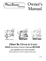
(Must Be Given to User)
READ this entire Owner's Manual BEFORE
you operate your new scooter!
See inside front cover for special instructions.
PN 16619
Revised 0610
SMAN0610.INDD
-48-
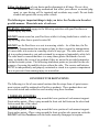
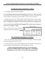
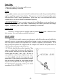
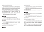
"SPECIAL OPTION" WARNINGS
SEAT MOUNT INFORMATION
CAUTION: Some seats have a second
set of mounting holes.
The front hole location can provide1"
extra leg room.
If the front set of holes is used, it will
reduce the maximum incline rating of
the vehicle by 3 degrees.
See owners manual for max. incline
specifications of your particular model
based on your weight.
-47-
Table of Contents
THIS MANUAL COVERS MANY DIFFERENT STYLES OF PaceSaver® SCOOTERS.
BE SURE AND FIND THE INFORMATION THAT PERTAINS TO YOUR STYLE.
Introduction
2
Important Safety Information
3
PaceSaver Specifications
8
Getting On and Off The PaceSaver
12
Operating the PaceSaver
13
Your First Ride
16
The PaceSaver Braking Systems
17
Brake Disengage Mechanism
18
Seat Assembly Operation
19
Disassembly & Assembly
22
Charging Your Batteries
24
General Care & Maintenance Section
33
Trouble-Shooting
36
Commonly Asked Questions and Possible Answers
38
Addendums
41
PN 16619
Revised 0610
SMAN0610.INDD
-1-
PaceSaver OWNERS MANUAL
Introduction
Congratulations on your choice of a PaceSaver Scooter! It is a dependable
vehicle built for power and performance. The PaceSaver’s rear wheel drive system will outperform front wheel drive styles on any surface, indoors or out. It
has excellent handling characteristics and its compact design makes it agile in
even the smallest places. The PaceSaver’s patented separation makes it easy
to assemble and disassemble. It's easy to operate controls give you more of what
you are looking for in a scooter.
But it is important that you understand what your scooter is, and what it is
not. PaceSaver scooters are designed to provide safe, reliable transportation to
older or mildly physically handicapped individuals who have difficulty in getting
around. It will safely take you everywhere the specifications indicate as long as
you follow the simple safety guidelines shown on the next few pages.
PaceSavers (like all scooters) are not all terrain vehicles that you can use out
in the fields to drag brush around or climb steep hills. They were not meant to
go hunting in, or transport you thru hazardous environments. They also are not
designed for the severely handicapped individual who is trying to avoid a power
wheelchair. You must have good stability, motor control and above all else, good
common sense to use our scooter or any other brand. If you feel that you cannot
safely operate this vehicle at all times you should not use a scooter!
Important Please read the entire manual carefully before attempting to
drive your new PaceSaver.
Remember to read all service recommendations outlined in this manual to
achieve trouble free, safe and enjoyable operation of your PaceSaver. Failure to
follow the recommended service procedures will damage your scooter and such
damage is not covered under warranty. Contact your dealer if you have questions
after reading this manual.
-2-
Leisure-Lift, Inc. specifically disclaims responsibility for any bodily injuries
or property damage which may occur during any use which does not comply with
applicable Federal, State, or Local laws and ordinances or methods recommended
in this manual. If in doubt about your ability to operate your PaceSaver, consult
your doctor.
NOTE: MODIFYING AND/OR TAMPERING IN ANY UNAUTHORIZED
MANNER WITH THE SCOOTER WILL VOID THE WARRANTY AND MAY
CAUSE THE SCOOTER TO MALFUNCTION, EXPOSING YOU TO PHYSICAL HARM.
ATTENTION: This manual covers several styles of the PaceSaver. While most
of the information is the same for all styles, make sure that the specifications you
are reading applies to the particular styles you have. If you are unsure of the
styles PaceSaver you have, contact your dealer.
Your PaceSaver is a vehicle which provides independence and freedom to people
with limited mobility. Driver error can cause injury to the driver and to other
people. Please use common sense, courtesy, and obey the following guidelines for
vehicle operation.
READ THIS ENTIRE MANUAL
BEFORE DRIVING THIS VEHICLE.
Safety Guidelines
Always turn the key switch to the OFF position when stopped or when getting off
or on the PaceSaver. This keeps you from accidentally hitting the throttle and
causing an accident. For persons with limited lower body strength, or persons
who make slide transfers and may forget to turn the key switch off, we recommend the use of the delta tiller option. Delta tillers can limit access to controls
for people with limited hand flexibility - Fingertip controls may be required.
Use extra caution when riding your PaceSaver off of the pavement or on rough, uneven
surfaces or tipping and injury will result. If you intend to operate your PaceSaver
on rough, uneven surfaces, and are willing to sacrifice indoor maneuverability,
consider our Wide Tire Option (not available on certain styles) for increased
stability.
-3-
Do not exceed the incline specifications for the style of PaceSaver that you own or it will
become unstable and tipping will result. Persons with limited ability to protect themselves (like persons paralyzed on one side) should use protective equipment such as
bicycle headgear. The specification chart in your manual will indicate the maximum
incline for your particular style.
Keep your feet on the floorpan while riding the PaceSaver to avoid hitting them on
objects as you drive.
Lock the seat assembly before operating the PaceSaver to prevent yourself from falling
from the seat while moving.
Remember, The PaceSaver is built to carry a single person. Do not carry passengers under
any circumstances or accidents and bodily injury will occur.
Always go straight up or down curb cuts or a ditch, not at an angle. You want the front wheels
and the rear wheels to climb up or go down together, not one at a time. Not doing this
will result in the steering tiller violently swinging from side to side (as a car would in
a ditch) or the scooters overturning. Also approach curb access ramps the same way,
straight on, not at an angle. NEVER attempt to go up or down a regular height curb or
tipping and personal injury will result!
Driving the PaceSaver in busy streets, busy parking lots, or in crowded shopping malls can
be dangerous for you or other people as you may be struck by a vehicle or you might
strike a pedestrian. Use caution in congested areas at all times. WARNING, Driving at night or around large vehicles is dangerous as it makes it difficult for drivers to
see you. Being struck or crushed by vehicles can result in death.
Lean forward a slight amount when traveling up an incline.
NEVER leave your scooter exposed to the elements. This includes storage outside or carrying
the scooter on an outside car-lift during periods of high moisture
( mist, rain, snow, etc.) or any other inclement weather (dust or sand storms, etc.).
Severe damage or malfunction can result.
Use caution when driving off of a curb or raised surface. The act of dropping off the edge
subjects the scooter to extreme forces that can damage the frame and other components.
This type of damage is not covered under warranty.
Disconnect the batteries before performing any maintenance beneath the seat or on the
tiller. This avoids both the possibility of injuries due to shock or accidental movement
of the scooter. Make sure that the batteries are secure when you are using the scooter.
-4-
Follow the directions of your doctor and/or pharmacist at all times. Do not drive
the PaceSaver while taking medications that affect your reflexes or mental judgment, as your driving will be impaired and accidents may result. Do not drink
alcohol and operate this or any other vehicle.
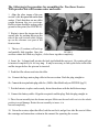
The following are important things to help you drive the PaceSaver in the safest
possible manner. Please take note of each one.
WARNING: DO NOT engage in the following activities with your PaceSaver or
serious injury may result.
DO NOT remain seated on your PaceSaver while it is being loaded into a vehicle using anything other than a special scooter lift.
DO NOT use the PaceSaver as a seat in a moving vehicle. As of this date, the Department of Transportation has not approved any tie down system for transportation
of a user while in a scooter in a moving vehicle of any type. The rider must be seated in a regular automotive seat and restrained by an approved automobile safety belt.
The rider must be warned that there is a many times greater likelihood of severe
injury or death in the event of an accident if they are not in the provided automotive
seat and restraint system. The following attachment points are provided for the sole
purpose of securing the mobility device without the rider. The scooter and batteries
MUST be independently and properly restrained or stored in a separate compartment
so as to prevent it from causing injury in an accident.
CONVENIENT TIE DOWN POINTS
The following is a list of convenient locations that the straps from a 4 point securement system could be anchored on PaceSaver products. These products have not
been crash tested and certified as crash worthy using these locations.
3 WHEELED SCOOTERS
Back anchor points - Place a strap around the lower portion of each armrest support.
Front anchor points - Place a strap around the front axle bolt between the wheel and
fork on each side of the wheel.
4 WHEELED SCOOTERS
Back anchor points - Place a strap around the lower portion of each armrest support.
Front anchor points - Place a strap around the front crossbar axle mount on each side.
DO NOT ride the PaceSaver with the brake manually disengaged at anytime.
-5-
DO NOT drive the PaceSaver diagonally across inclines, turn sharp or make turns at
or near full throttle at any time. Doing this will result in overturning and serious
personal injury can result.
DO NOT drive the PaceSaver with the seat assembly higher than necessary as tipping
and serious injury may result. The lower the seat, the better your stability.
DO NOT drive the PaceSaver with under-inflated tires as this increases the possibility
of tipping and injury. Your stability and efficiency (power and range) are also
greatly affected. Filled tires are available if you are unable to check your tire pressure.
DO NOT stop on any incline to rest or dismount. Although the electric brake will stop
and hold you, it is best to stop in level, flat areas where there is no possibility of
rolling or tipping the unit.
DO NOT drive on inclines greater than the rating for your style PaceSaver or
tipping will result. Refer to the Specification Sheet and Ramp Incline Chart else
where in this manual.
DO NOT allow the PaceSaver controls to become wet. Never wash off the scooter
using a hose or a stream of water, drive through standing water or ride in the rain.
Possible loss of control and/or electronic damage will occur. Do not attempt to ride a
scooter that has been soaked until it has had a chance to dry thoroughly.
DO NOT leave the PaceSaver where it is exposed to high temperatures (a car trunk,
etc.) or to poor weather conditions such as rain or snow or freezing conditions as
damage to the unit will occur.
DO NOT disassemble any wheel at any time while still inflated. The pressure may
blow wheel rims apart while you are loosening them.
DO NOT ride the unit near stairs, ledges or in any other potentially dangerous situation.
DO NOT ride the scooter over power cords, oxygen lines, hoses or any other material
that could become entangled in the wheels or get caught in the drive mechanism of the
scooter or while connected to equipment off of the scooter, as serious injury may result.
-6-
Persons having disabilities which limit their ability to remain erect without assistance,
(stroke patients, severe muscular diseases, etc.) should carefully evaluate whether they
should operate a scooter at all. If they decide, with the advise of their physician or another advisor, that they are capable of safely operating a scooter, they should consider
the use of a bicycle helmet or pads when operating a scooter. These articles would help
protect them should they find themselves in a hazardous situation where they could
tip over because of their lack of balance. The controller can also be programmed to
fit your requirements.
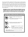
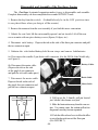
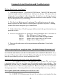
DIFFERENT STYLES OF SCOOTERS HAVE DIFFERENT INCLINE
CLIMBING ABILITIES. CAREFULLY STUDY THE CHART TO SEE THE
CORRECT SPECIFICATIONS FOR YOUR UNIT. DO NOT EXCEED THE
SPECIFICATIONS OF THE SCOOTER STYLE YOU PURCHASED!
RAMPS, STEEP TERRAIN, CURBS, STEPS & RIDER TRANSFER
DO NOT drive on ramps or steep terrain greater than
12 degrees.
DO NOT attempt to drive your scooter backward down
any step, curb or any other obstacle.
DO NOT drive near raised surfaces, unprotected ledges,
and/or drop-offs (curbs, porches, stairs, ect.).
USE CURB CUTS whenever possible to go up and
down curbs.
Always drive straight up/down or perpendicular
to curbs or curb cuts. Never traverse at an angle.
RIDER TRANSFER: Refer to the section of the owners manual titled
'Getting On and Off the PaceSaver'.
-7-
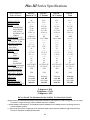
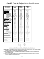
Plus III Series Specifications
Spec's subject to
slight variations
OVERALL LENGTH
OVERALL WIDTH
WEIGHT
REAR DRIVE UNIT
BASE AND TILLER
SEAT SECTION
BATTERY & CASE
SHROUD
MAXIMUM SPEED (M.P.H.)
RANGE*(On one charge) (MILES)
Group 22 Batt. / U1 Batt.
GROUND CLEARANCE
Below Transaxle
Below Frame
TURNING RADIUS
TIRE SIZE
FRONT
REAR
SEAT DIMENSIONS
WIDTH
DEPTH
BACK HEIGHT
SEAT HEIGHT (from floorpan)
W/POWER SEAT
ELECTRONIC BRAKES
(Regenerative & Dynamic)
ADD. SAFETY BRAKING
("Posi-Lock" Disk Brake)
DRIVE TYPE
MOTOR SIZE
INCLINE STABILITY**
STRUCTURAL CAPACITY***
Plus III
Junior 10"/9"
Plus III
9" Premier
Plus III
10" Premier
Plus III
Titan
42"
24" / 23.5"
-------45 lbs.
37 lbs.
25 lbs.
25 lbs. ea.
-------5.25 / 4.3
14 (U1 Batt)
--------------2.5" / 2"
4.5" / 4.25"
36"
-------2.5" X 9"
10" / 9"
-------18"
18"
16"
16.75" TO 18.75"
18" TO 23"
YES
45.5"
23.5"
-------42.5 lbs.
34.5 lbs.
23.75 lbs.
25 lbs. ea.
-------4.3
14 (U1 Batt)
--------------2"
4.25"
39"
-------2.5" X 9"
3" X 9"
-------18"
18"
20"
16.75" TO 18.75"
18" TO 23"
YES
45.5"
24"
-------43.3 lbs.
35 lbs.
23.75 lbs.
25 lbs. ea.
-------5.25
14 (U1 Batt)
--------------2.5"
4.5"
39"
-------3" X 9"
3" X 10"
-------18"
18"
20"
16.75" TO 18.75"
18" TO 23"
YES
45.5"
24."
-------43.3 lbs.
35 lbs.
24.5 lbs.
25 lbs. ea.
-------5.25
21 / 13
--------------2.5"
4.5"
39"
-------3" X 9"
3" X 10"
-------18"
18"
20"
16.75" TO 18.75"
18" TO 23"
YES
YES
YES
YES
YES
Transaxle
1 1/4 HP
16% Grade
300 LBS.
Transaxle
1 1/4 HP
22% Grade
300 LBS.
Transaxle
1 1/4 HP
22% Grade
300 LBS.
Transaxle
1 1/4 HP
22% Grade
350 LBS.
9 degrees = 16%
10 degrees = 17.6%
12 degrees = 22%
Do Not Exceed The Maximum Incline Stability For Your Style Scooter!
* Range tested to the US Ansi/Resna Standard with product maximum weight capacity. Customer's range may vary according
to customer's weight, terrain type, battery condition and/or tire condition.
** Incline stability is determined per US Ansi/Resna Dynamic Stability test 8.2. Stability increases by leaning forward or
seat not in highest position.
*** Approved for use by riders weighing up to the maximum weight capacity shown in addition to approved Leisure Lift
accessories and options available for that model.
-8-
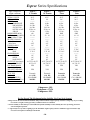
Plus III Cont. & Eclipse Series Specifications
Spec's subject to
slight variations
OVERALL LENGTH
OVERALL WIDTH
WEIGHT
REAR DRIVE UNIT
BASE AND TILLER
SEAT SECTION
BATTERY & CASE
SHROUD
MAXIMUM SPEED (M.P.H.)
RANGE*(On one charge) (MILES)
Group 22 Batt. / U1 Batt.
GROUND CLEARANCE
Below Transaxle
Below Frame
TURNING RADIUS
TIRE SIZE
FRONT
REAR
SEAT DIMENSIONS
WIDTH
DEPTH
BACK HEIGHT
SEAT HEIGHT (from floorpan)
W/POWER SEAT
ELECTRONIC BRAKES
(Regenerative & Dynamic)
ADD. SAFETY BRAKING
("Posi-Lock" Disk Brake)
DRIVE TYPE
MOTOR SIZE
INCLINE STABILITY**
STRUCTURAL CAPACITY***
Plus III
Atlas
Eclipse
Premier
Eclipse
Atlas
45.5"
26.5"
-------43.3 lbs.
45 lbs.
29.75 lbs.
25 lbs. ea.
-------5.25
18 / 12
--------------2.5"
4.5"
39"
-------3" X 9"
3" X 10"
-------21"
21"
22"
16.75" TO 18.75"
18" TO 23"
YES
49.75"
24"
-------41 lbs.
59 lbs.
24.5 lbs.
25 lbs. ea.
3.5 lbs.
5.25
21 / 12
--------------2.5"
4.5"
56.5"
-------3" X 10"
3" X 10"
-------18"
18"
20"
16.75" TO 18.75"
18" TO 23"
YES
49.75"
26.5"
-------41 lbs.
61 lbs.
29.75 lbs.
25 lbs. ea.
3.5 lbs.
5.25
16 / 9
--------------2.5"
4.5"
56.5"
-------3" X 10"
3" X 10"
-------21"
21"
22"
16.75" TO 18.75"
18" TO 23"
YES
YES
YES
YES
Transaxle
1 1/4 HP
17.6% Grade
450 LBS.
Transaxle
1 1/4 HP
22% Grade
350 LBS.
Transaxle
1 1/4 HP
17.6% Grade
450 LBS.
9 degrees = 16%
10 degrees = 17.6%
12 degrees = 22%
Do Not Exceed The Maximum Incline Stability For Your Style Scooter!
* Range tested to the US Ansi/Resna Standard with product maximum weight capacity. Customer's range may vary according
to customer's weight, terrain type, battery condition and/or tire condition.
** Incline stability is determined per US Ansi/Resna Dynamic Stability test 8.2. Stability increases by leaning forward or
seat not in highest position.
*** Approved for use by riders weighing up to the maximum weight capacity shown in addition to approved Leisure Lift
accessories and options available for that model.
-9-
Espree Series Specifications
Spec's subject to
slight variations
OVERALL LENGTH
OVERALL WIDTH
WEIGHT
REAR DRIVE UNIT
BASE AND TILLER
SEAT SECTION
BATTERY & CASE
SHROUD
MAXIMUM SPEED (M.P.H.)
RANGE*(On one charge) (MILES)
Group 22 Batt. / U1 Batt.
GROUND CLEARANCE
Below Transaxle
Below Frame
TURNING RADIUS
TIRE SIZE
FRONT
REAR
SEAT DIMENSIONS
WIDTH
DEPTH
BACK HEIGHT
SEAT HEIGHT (from floorpan)
W/POWER SEAT
ELECTRONIC BRAKES
(Regenerative & Dynamic)
ADD. SAFETY BRAKING
("Posi-Lock" Disk Brake)
DRIVE TYPE
MOTOR SIZE
INCLINE STABILITY**
STRUCTURAL CAPACITY***
Espree
9" Premier
Espree
Atlas
Espree
10" Premier
Espree
Titan
45.5"
23.5"
-------40 lbs.
36.5 lbs.
24.5 lbs.
25 lbs. ea.
3.5 lbs.
4.3
23 / 14
--------------2"
4.25"
39"
-------2.5" X 9"
3" X 9"
-------18"
18"
20"
16.75" TO 18.75"
18" TO 23"
YES
45.5"
24"
-------41 lbs.
37 lbs.
24.5 lbs.
25 lbs. ea.
3.5 lbs.
5.25
23 / 14
--------------2.5"
4.5"
39"
-------3" X 9"
3" X 10"
-------18"
18"
20"
16.75" TO 18.75"
18" TO 23"
YES
45.5"
24"
-------41 lbs.
37 lbs.
24.5 lbs.
25 lbs. ea.
3.5 lbs.
5.25
21 / 13
--------------2.5"
4.5"
39"
-------3" X 9"
3" X 10"
-------18"
18"
20"
16.75" TO 18.75"
18" TO 23"
YES
45.5"
26.5"
-------41 lbs.
45 lbs.
29.75 lbs.
25 lbs. ea.
3.5 lbs.
5.25
18 / 12
--------------2.5"
4.5"
39"
-------3" X 9"
3" X 10"
-------21"
21"
22"
16.75" TO 18.75"
18" TO 23"
YES
YES
YES
YES
YES
Transaxle
1 1/4 HP
22% GRADE
300 LBS.
Transaxle
1 1/4 HP
22% GRADE
300 LBS.
Transaxle
1 1/4 HP
22% GRADE
350 LBS.
Transaxle
1 1/4 HP
17.6% GRADE
450 LBS.
8 degrees = 14%
10 degrees = 17.6%
12 degrees = 22%
Do Not Exceed The Maximum Incline Stability For Your Style Scooter!
* Range tested to the US Ansi/Resna Standard with product maximum weight capacity. Customer's range may vary according
to customer's weight, terrain type, battery condition and/or tire condition.
** Incline stability is determined per US Ansi/Resna Dynamic Stability test 8.2. Stability increases by leaning forward or
seat not in highest position.
*** Approved for use by riders weighing up to the maximum weight capacity shown in addition to approved Leisure Lift
accessories and options available for that model.
-10-
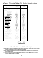
Espree 500 and Eclipse 500 Series Specifications
Spec's subject to
slight variations
OVERALL LENGTH
OVERALL WIDTH
WEIGHT
REAR DRIVE UNIT
BASE AND TILLER
SEAT SECTION
BATTERY & CASE
SHROUD
MAXIMUM SPEED (M.P.H.)
RANGE*(On one charge) (MILES)
Group 22 Batt. / U1 Batt.
GROUND CLEARANCE
Below Transaxle
Below Frame
TURNING RADIUS
TIRE SIZE
FRONT
REAR
SEAT DIMENSIONS
WIDTH
DEPTH
BACK HEIGHT
SEAT HEIGHT (from floorpan)
W/POWER SEAT
ELECTRONIC BRAKES
(Regenerative & Dynamic)
ADD. SAFETY BRAKING
("Posi-Lock" Disk Brake)
DRIVE TYPE
MOTOR SIZE
INCLINE STABILITY**
STRUCTURAL CAPACITY***
Espree
Atlas 500
Eclipse
Atlas 500
45.5"
26.5"
-------41 lbs.
45 lbs.
29.75 lbs.
25 lbs. ea.
3.5 lbs.
5.25
17 / 11
--------------2.5"
4.5"
39"
-------3" X 9"
3" X 10"
-------21"
21"
22"
16.75" TO 18.75"
18" TO 23"
YES
49.75"
26.5"
-------41 lbs.
61 lbs.
29.75 lbs.
25 lbs. ea.
3.5 lbs.
5.25
15 / 9
--------------2.5"
4.5"
56.5"
-------3" X 10"
3" X 10"
-------21"
21"
22"
16.75" TO 18.75"
18" TO 23"
YES
YES
YES
Transaxle
1 1/4 HP
14% GRADE
500 LBS.
Transaxle
1 1/4 HP
14% GRADE
500 LBS.
8 degrees = 14%
10 degrees = 17.6%
12 degrees = 22%
Do Not Exceed The Maximum Incline Stability For Your Style Scooter!
* Range tested to the US Ansi/Resna Standard with product maximum weight capacity. Customer's range may vary according
to customer's weight, terrain type, battery condition and/or tire condition.
** Incline stability is determined per US Ansi/Resna Dynamic Stability test 8.2. Stability increases by leaning forward or
seat not in highest position.
*** Approved for use by riders weighing up to the maximum weight capacity shown in addition to approved Leisure Lift
accessories and options available for that model.
-11-
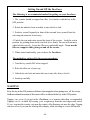
Getting On and Off the PaceSaver
The following is a recommended method for getting on your PaceSaver.
1. The scooter should be stopped on a flat, level surface with the key in the
OFF position.
2. Rotate the unlocked seat assembly to one side & re-lock.
3. Position yourself squarely in front of the seat and lower yourself into the
seat using the armrests if necessary.
4. Unlock the seat and rotate toward the front of the scooter. Lock the seat in
position by pushing down on the seat lock lever firmly. The seat will not move
when locked correctly. Lower the tiller to a comfortable angle. Never use the
tiller as a support while getting on and off the scooter.
5. When seated comfortably, you can drive the PaceSaver.
The method for getting off is the reverse procedure.
1. Turn the key switch OFF when stopped.
2. Raise the tiller out of your way.
3. Unlock the seat lock and rotate the seat to one side, then re-lock it.
4. Stand up carefully.
WARNING
Keep the key in the OFF position at all times when stopped or when getting on or off the scooter.
Sudden accidental movement of the scooter will be avoided with the key in the OFF position.
Tipping can occur if you get on the PaceSaver in a manner other than recommended.
Tipping can be avoided by keeping your weight away from the outer edges until seated.
If you step into the scooter, step near the center of the floorpan, not near the edge. Tipping
can also occur if you turn the steering tiller sharply while traveling at or near full throttle.
-12-
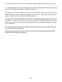
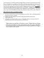
Operating the PaceSaver
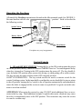
All controls for PaceSaver operation are located on the tiller mounted panel (See FIGURE 1).
Become familiar with all controls with
the key in the OFF position. Each is described in
Control
Console
the following section.
Key Switch
Speed Control
Battery Meter
FIGURE 1
Throttle Lever
Horn Button
Faceplates may vary in appearance.
Control Console
1. ON and OFF KEY SWITCH. Turning the key to the ON position turns the power
on. In this position, the key cannot be removed. NOTE: There is a 3 second diagnostic delay
when key is turned on. Turning to the OFF position turns the power off. The key should always be in the OFF position when you are not driving, or when getting off or on the scooter.
The key can only be removed when in the OFF (stopped) position.
SAFETY INFORMATION - The key switch can also be used as a master switch for the
scooter's braking system. In the improbable event that the scooter should fail to stop or return
to the off position, turning the key switch to the off position automatically and immediately
causes the brake to engage and the scooter to come to a quick halt. Use great care in this situation to avoid an accident!
ATTENTION: When using the scooter key ring, DO NOT attach additional keys or accessories to the key ring. These additional weights, coupled with scooter vibrations, may cause
the to key to momentarily move to the OFF position. This occurrence may cause the scooter
to come to a sudden stop.
-13-
NOTE: The battery indicator will tell you if power is applied. The indicator only works when
the key is switched ON and all battery connections are made.
Your scooter is equipped with a battery saver circuit. It will shut off the controller after 20
minutes of non-use (even with your key "ON"). The system is reset by turning the key "OFF"
and back "ON" again.
2. SPEED SETTING KNOB. Use this knob, located to the left of the key switch, to
dial in the scooter's top speed and power. Rotate the dial counterclockwise toward the turtle
(1) for use indoors or in tight areas where speed is not required. A higher setting toward the
rabbit (10) is suitable for outdoors and open areas where higher speeds are manageable. When
driving on difficult terrain or for persons with more limited physical control, use a lower top
speed setting. If you set the knob between 5 & 10, the control's "power boost" feature will
automatically increase power to maintain the top speed you are comfortable with. Should
you not be able to use the speed control knob, your dealer can program the control for a
slower top speed.
3. BATTERY METER. This meter indicates the charge condition of the batteries
while you are driving. The batteries are in a good charge condition if the needle is in the
green area while you are driving. The needle in the red area while driving corresponds
to a low charge. It is possible to drive the scooter with the needle in the red area for a short
time. You must charge the batteries as soon as possible. Refer to the battery charging section for more information.
4. HORN. The white button on the front of the control panel is the horn button.
Simply pressing it sounds the horn.
5. THROTTLE LEVER. The black lever under the control panel is the throttle
lever. Push the lever slowly with your thumb in the direction of the arrows on the control
faceplate to make the scooter go forward or reverse. Pushing the lever in slightly will make
the scooter begin to move. The further you depress the lever the faster the scooter moves.
The top speed set by the SPEED knob is reached by fully depressing the throttle lever.
Completely releasing the throttle bar will stop power to the motor and activate the brakes
as you come to a complete stop. EMERGENCY STOPS - To stop quickly while driving
in forward or reverse, change throttle bar direction (i.e. when going down an incline, to stop
quickly move the throttle bar from forward to reverse.) Release the bar quickly to avoid driving in the opposite direction.
PLEASE NOTE: Should the throttle /brake control system not stop the unit, turning the
key switch off will engage all brakes and bring the unit to a smooth stop. This backup system
should only be used in the unlikely event that the primary brake control is disabled, as it puts
an added stress on the components.
-14-
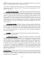
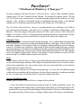
"SOFT TOUCH" TILLER INFORMATION SHEET
PACESAVER SCOOTERS ARE EQUIPPED WITH A "SOFT TOUCH" TILLER
FIGURE 2
HEADLIGHT - The headlight is operated by the switch located on the back panel of the tiller.
TURN SIGNAL - If your scooter has the optional turn signals, it will have push button switches located
on the sides of the tiller. CAUTION: The headlights and optional turn signals must be shut off after use to
prevent discharging your batteries.
TILLER PIVOT MECHANISM - The tiller angle can be adjusted from vertical to horizontal. To make
adjustments, push on the release lever while moving the tiller closer or farther away for yourself. Let go
of the release lever to lock the tiller into position (See FIGURE 2).
CHARGER CONNECTIONS
ON-BOARD CHARGER - If you have an on-board charger it will be mounted on the scooter.
You will have a charger cord with a 110 VAC plug on one end and a 3 pin rectangular plug on the
opposite end. Plug the cord into the rectangular charger port on the back plate and the opposite end
into and AC outlet. Refer to the battery charging section in this manual for more information
(See FIGURE 2).
OFF BOARD CHARGERS - If you have an off board charger, it will not be mounted on the
scooter. You will have a charger with a cord having an AC plug on one end and a cord with a
round plug on the other end. Connect the round plug to the tiller back plate and plug the AC cord
to an AC outlet. Refer to the battery charging section in this manual for more information
(See FIGURE 2).
NOTICE: The battery charger provided is specially designed for use with PaceSaver brand equipment.
In the unlikely event of failure it should be replaced only with a PaceSaver approved charger to assure
proper performance ot the charger and scooter.
-15-
For your first ride we recommend the following.
1. Make sure the area is flat, open and free of obstacles.
2. Make sure the tiller is properly adjusted to fit your driving needs. Refer to the "Soft Touch" Tiller
section in this manual for more information.
3. Make sure the seat is in the locked position (handle is down).
4. Turn the SPEED setting knob to the turtle (1) .
5. Turn the key switch to ON.
6. Push the throttle lever on the “F” side (“F” for Forward) with your thumb to go forward.
7. SLOWLY rotate the SPEED setting knob from the turtle position. Rotate the knob until the
desired top speed is reached.
8. Release the throttle lever to come to a stop. Take note of how the braking feels. The clicking you
might hear upon starting and shortly after releasing the throttle lever is the Posi-Lock Electric
Disk Brake disengaging and engaging.
9. Push the throttle lever on the “R” side (“R” for Reverse) with your thumb to go backward. There is
a factory set forty percent (40%) reduction in speed in the reverse direction WITHOUT any change
in the SPEED SETTING KNOB. Always make sure the area behind you is clear before backing up.
10. Remember to turn the key OFF when not driving or getting on or off the scooter.
WARNING
PaceSavers are designed for high maneuverability, but use caution when encountering obstacles. Failure
to drive cautiously can result in tipovers or collisions which may cause physical injury. When approaching
an obstacle keep your speed at a minimum and maintain a safe distance from that object.
BE PREPARED TO STOP. Avoid any small objects on the ground. The scooter's ground clearance may be
less than the size of the object. Running over an object or into a depression could cause overturning or
damage to the scooter. NEVER ride the unit near platforms, stairs, ledges, curbs or in any other potentially
dangerous situation as severe injury can occur.
WARNING
PaceSaver Titan and Atlas models are high performance vehicles. As with Sport Utility Vehicles they require
more caution when operating. Because of the extra power and speed they are more susceptible to tipping
in rough terrain and tight turns at high speed. Serious injury can result. For that reason you should always use
caution when operating at higher speed.
Remember, speed can be "Dialed Down" using the speed setting knob on the control console without losing power to run at the slower speed. If necessary, the unit can be permanently programmed by your dealer
to operate at a speed more suitabe for your control. Use caution while learning to operate this vehicle and
consult your dealer if you have any problems. This unit should not be used by people with limited physical
upper body strength.
-16-
The PaceSaver Braking Systems
The PaceSaver’s brake systems allow for smooth start up and safe braking without
undue jerking. There are three (3) separate modes to the braking system: Regenerative,
Dynamic, and Posi-Lock Electric Braking. All braking occurs automatically during scooter
operation. Each type of braking is described in the following.
1. Regenerative Braking is activated while driving the PaceSaver down an incline.
When the scooter picks up speed going down the incline, the motor generates electricity.
This electricity is channeled back through the PaceSaver’s electronic control circuits to
recharge the batteries. This action keeps the scooter from picking up excess speed and provides for smooth speed control.
2. Dynamic Braking is activated WITHOUT delay when all power is stopped to
the motor by releasing the throttle lever, as when coming to a complete stop. This braking
works until the Posi-Lock Electric brake is activated.
3. Posi-Lock Electric Braking Disk is activated with delay when all power is stopped to
the motor. This electric brake has a short delay and ultimately holds the PaceSaver at a complete
stop. The scooter cannot be moved when this brake is activated. Dynamic Braking works in
conjunction with Posi-Lock Electric Braking to bring you to a gradual and complete stop.
PLEASE NOTE: Should the throttle /brake control system not stop the unit, turning the key
switch off will engage all brakes and stop the unit immediately. This backup system should
only be used in the unlikely event that the primary brake control is disabled, as it puts an
added stress on the components.
BRAKE DISENGAGE MECHANISM
The PaceSaver is equipped with a manual Brake Disengage Mechanism. This mechanism allows the scooter to be moved in the event the batteries are run low, or if there is a
malfunction.
Caution:
DO NOT ride the PaceSaver with the Brake Disengage Mechanism activated at any
time. Our "push-to-fast" circuit slows the unit down but does not stop it. DO NOT ride or
sit on the scooter with these systems disengaged or if the brakes are inoperative. Have the
system repaired immediately.
-17-
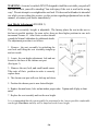
MANUAL BRAKE RELEASE FOR ALL PACESAVER SCOOTERS
Activating the disengage mechanism is as follows.
1. Be certain the scooter is on flat level ground.
2. Locate the Black release knob on the top right of the rear cover. Pull the black
knob up firmly until the cart freewheels. This disengages the Posi-Lock disc brake but
retains dynamic & regenerative motor braking if the key switch is turned on.
3. Always turn the key to the "OFF" position when the brake release is in the up position. This disengages the dynamic braking systems and initiates our exclusive "Push
to Fast" braking system which activates if the scooter rolls beyond a crawling speed.
Never sit on the scooter with the brake disengaged! The scooter can move unexpectedly and cause damage or injury.
Rear Cover Label
There is a label on the rear cover like this
to help you operate the disengage.
Deactivating the disengage is as follows.
1. First, press the black release knob back down until it is firmly seated in its original
position to engage the "posi-lock" brake.
2. Second, turn the key to the "OFF" and then to the "ON" position. All braking systems are again activated and normal scooter operation may resume.
SHOULD THE BRAKE DISENGAGE ON A SCOOTER EVER
APPEAR TO WORK POORLY OR INCORRECTLY, STOP RIDING
IMMEDIATELY AND CONTACT YOUR DEALER FOR SERVICE!
-18-
Seat Assembly Operation
PaceSavers come with three styles of armrests, each with their own adjustments. Each of
these armrests is designed to provide support for your arms while you are seated on the scooter, and for
some assistance when getting on and off of the scooter. THEY ARE NOT DESIGNED TO HOLD A PERSONS WEIGHT! Persons with limited use of their legs or without the ability to transfer their weight to the
floor should seek additional assistance (slide board, helper, etc.) when transferring on and off of the scooter.
Failure will result if excess weight is applied to the armrests.
Fixed armrest
adjustments
Variable Width
armrest adjustments
Armrest height
adjustments
Should the armrest angle change
over time, you can adjust the
angle back to level.
1. Loosen the black knobs
at the lower rear of the seat
Rotate counter clockwise
to loosen.
1. Remove the nut, bolt and
wedges holding the two piece
adjustable height armrest
together.
2. Slide the armrests in or
out
as needed.
2. Raise or lower the inside
piece of tubing to the preferred height.
1. Lift the armrest to the vertical
position.
2. Loosen one of the two nuts that
hold the adjustment bolt in place..
3. Turn the top nut, turning it
up or down, depending on the
needed adjustment, and test for
the correct armrest height.
4. When you have the correct
angle, tighten the bottom nut.
3. Tighten the black knobs.
Rotate clockwise to tighten.
Should you wish to remove
the armrests, simply pull them
out when the knobs are loose.
Remember to tighten the
knobs to avoid their loss.
3. Install the nut, bolt and
wedges used to hold the tow
piece adjustable height armrest together.
The PaceSaver seat rotates 360 degrees. The seatlock allows you to lock the seat
in any position. Seatlock operation is as follows.
1. Rotate the seat to the desired position.
2. Push the lever forward firmly until it is down and the seat will not swivel.
3. When properly locked, the seat will not rotate while you are riding the
scooter (see warning).
4. To unlock, pull up on the lever. The seat will now swivel freely. Take care when
assembling the cart that the seat lock lever is upright and all the way down on the seat
post to avoid damage to the seat lock mechanism and so that the seat slips on easily.
Failure to do this will damage the seatlock!
-19-
WARNING: A scooter's seatlock IS NOT designed to hold the seat while you push off
one side to assist yourself in standing! You risk injury if the seat is used in the wrong
way! Do not attempt to overtighten the seat lock. If it does not hold under its intended
use while you are riding the scooter, see the section regarding adjustment later in this
manual, or contact your dealer immediately!
Seat Height Adjustment (FIGURE 3)
The seat assembly height is adjustable. The factory places the seat in the next to
the lowest possible position. On some styles, there are three higher positions in one inch
increments Owners of Atlas Series scooters should
consult the Manual Addendum for additional details.
The adjustment procedure is as follows.
1. Remove the seat assembly by unlocking the
seat lock and lifting the seat assembly straight up
and set it aside.
2. Locate the seat height adjustment bolt and nut
located at the base of the chrome seat post
(See figure 3).
3. Remove the nut, bolt, and small metal cones.
Take note of their position in order to correctly
replace them.
FIGURE 3
4. The chrome seat post will now slide up and down.
5. Position the chrome post to new desired height.
6. Replace the metal cones, bolt, and nut in their proper order. Tighten until all play is eliminated.
7. Replace the seat assembly and test the new height.
It is recommended that the seat assembly be positioned at the lowest possible comfortable
seat height. PaceSaver stability will be improved at the lower height.
-20-
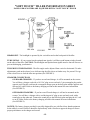
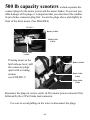
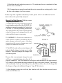
500 lb capacity scooters include separate disconnect plugs for the motor power and the motor brakes. To prevent possible damage of the plugs, it is important that you disconnect the smaller
(2-pin) brake connector plug first. Locate the plugs above and slightly in
front of the drive motor. (See FIGURE 4)
FIGURE 4
Battery Cables
Brake Cable
(2-Pin)
Motor Cable
(4-Pin)
Pressing down on the
latch release lever, pull
the connector plugs
apart with a rocking
motion.
(see FIGURE 5)
Battery Cables
Brake Cable
(2-Pin)
Motor Cable
(4-Pin)
FIGURE 5
Reconnect the plugs in reverse order, (4-Pin) motor power connector first,
followed by the (2-Pin) brake lead connector.
Use care to avoid pulling on the wires to disconnect the plugs.
-21-
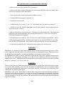
Disassembly and Assembly of the PaceSaver Scooter
The PaceSaver’s patented separation makes it easy to disassemble and assemble.
Complete disassembly can be accomplished in seconds WITHOUT tools.
1. Remove the key from the switch. (It should already be in the OFF position since
it was placed there when you last got off the scooter).
2. Remove the armrests from the seat assembly if you find this more convenient.
3. Unlock the seat lock, lift the seat assembly upward and set it aside. Lift off the rear
cover on units with one piece battery covers (Epsree, Eclipse, etc.).
4. Disconnect each battery. Depress the tab on the side of the three pin connector and pull
the two connectors apart.
5. Unfasten the velco backed battery hold down straps and remove both batteries.
6a. Disconnect the smaller 2-pin brake cable connector (for the 500 lb Atlas Model only,
see Figure 6).
6b. Disconnect the motor cable.
(Depress the tab on the side
of the single 4-pin connector
and pull the two cable ends apart.)
7. Disconnect the motor cable.
Depress the tab on the side of
the single four pin connector and
pull the two connectors apart.
Battery Cables
Brake Cable
Motor Cable
FIGURE 6
8. Pull up on the L-handle pull pin located
just behind the chrome seat post.
9. Slide the front section away from the rear section. Use caution since the sections will rock to
the ground once they become separated.
Tiller
Release
Lever
FIGURE 7
10. Push the tiller release lever to allow the tiller
to pivot backwards toward the floor pan
(See FIGURE 7).
-22-
The following is the procedure for assembling the PaceSaver Scooter.
With practice this will become easier and easier.
1. Align the silver tongue of the rear
section with the square tube on the front
section. Check that there are no cables
caught between the two sections.
Both sections should be resting on the
ground at this point (See FIGURE 8).
2. Begin to insert the tongue into the
square tube by pushing down on the
rear of the rear section while lifting
up on the chrome seat post of the
front section.
3. The two (2) sections will rock up
and partially slide together. Once the
FIGURE 8
sections cannot be lifted any higher, slide them together completely.
4. Insert the L-shaped pull pin into the hole just behind the seat post. Be certain pull pin
is inserted completely to its stop ring. It may be necessary to line up the holes in the tube
and the tongue before the pin can be inserted.
5. Push the tiller release and raise the tiller.
6a. Connect the large motor plug cable to the rear section. Push the plug straight in.
6b. Connect the two-pin brake plug cable for. (500 lb. Atlas Model only. see FIGURE 4 pg 21)
7. Put the batteries in place and securely fasten them down with the hold down straps.
8. Connect the battery cables. Align the receptacle and the plug. Push the plug straight in.
9. Place the seat assembly into the chrome seat post. Make sure the seat lock lever is in the unlock
position to avoid damage. Rotate the seat assembly to insure it is
lowered completely.
10. Get on the scooter, adjust the tiller, lock the seat lock, and go for a ride. Be sure to follow
the warnings and instructions written in this manual for operating the scooter.
-23-
THE SCOOTER BATTERIES
Charging the batteries is the most important part of operating and maintaining your scooter.
Be sure to do it properly! IMPORTANT: Only AGM or gelcell sealed lead-acid deep
cycle discharge type batteries should be used with this scooter. Do not use regular car
starter batteries. AGM and gelcell batteries do not require water and they have no danger
of spillage. Some are approved by the Federal Aviation Administration for air travel.
NOTICE: The battery charger provided is specially designed for use with PaceSaver
brand equipment. In the unlikely event of failure it should be replaced only with a PaceSaver approved charger to assure proper performance of the charger and scooter.
Important Safety Information:
Always use caution when lead-acid batteries are being charged. Batteries can generate explosive gasses during charging. Observe the follow guidelines to reduce risk of battery explosion.
1. Never smoke or allow open flame or sparks around a charging battery.
2. Never charge a frozen battery.
3. Use a PaceSaver charger designed for charging deep-cycle gelcell and AGM batteries.
4. The user is instructed to NOT use the charger with a battery configuration not
matching the output voltage rating of the charger. The batteries in this scooter are
connected for 24 volts.
5.The charger is rated at 24 volts DC and includes a special safety circuit to prevent
operation of the scooter while charging. This is to prevent accidently driving away
with the AC cord connected, causing damage to the cord and to the receptacle in the
user's residence.
6. Do not operate the charger in closed area or restrict ventilation around the charger
in any way.
7. Do not disconnect the DC portion of the charger circuit while the AC cord is still
connected to the electrical outlet.Unplug the AC cord first.
8. It is normal for the charger to operate at a high temperature. Do not touch the hot
charger until after it cools.
Basic Safety Instructions:
1. Do not expose the charger to rain, snow or other moisture sources (i.e., sprinkler, car
wash, etc.). When storing the scooter, keep it inside a building or under a protective covering.
2. Use of the charger in a manner not recommended by the manufacturer may result in the
risk of fire, electrical shock or personal injury.
3. To reduce the possibility of damage to the AC cord or the connector, disconnect the AC
line cord by grasping the plug and not the cord, when disconnecting from either the cart or
the wall receptacle.
4. Locate cord so that it will not be stepped on, tripped over or subjected to the possibility
of damage.
-24-
5. An extension cord is not recommended for use with this equipment. Use of an improperly
rated extension cord could result in risk of fire or electrical shock. Should it be required to
use an extension cord, make certain that it is of 3-wire construction and has a wire size of at
least 16-gage, and the cord must be in good electrical condition.
6. Do not operate this charger with damaged AC cord or receptacle. If they are damaged,
replace them immediately.
7. Do not disassemble the charger. If there is a perceived problem with the equipment,
refer to the servicing section of this manual or refer to a qualified technician for service.
Incorrect assembly of the charger could result in a risk of electrical shock or fire.
8. Do not operate the charger if it has received an impact of a severity that may render it
inoperative. Take it to a service technician.
9. To reduce the risk of electrical shock, unplug the charger from the electrical outlet before attempting any maintenance or cleaning.
10. Operate the charger on a flat surface. Restricting air flow around the charger can create
an overheated condition. Carpeted floors can restrict air flow. It is normal for the charger
to operate at a high temperature.
11. Do not operate the charger with a damaged cord or plug. Do not operate if the charger
looks like it has been damaged. Contact your dealer for repair.
12. Make sure the charging plug is seated fully in the scooter battery charger outlet.
13. Do not stand on wet surface while connecting charger.
Before Charging:
1. Verify that battery terminals are clean and that all charger connections are secure and in
good condition.
2. Verify that all cords and cables are in good condition.
Grounding and AC Power Connection:
The charger must be plugged into a grounded electrical outlet. The unit is provided with
an electrical cord which contains a conductor for grounding. The charger cord must be
plugged into an AC outlet that is properly installed, and is grounded in accordance with the
National Electrical Code and all local electrical codes and ordinances.
!! CAUTION !! - Failure to plug the charger into a grounded receptacle could cause a
condition allowing an electrical shock hazard to be present while charging.
++DANGER++ Improper connection of the equipment grounding conductor can result
in a risk of electrical shock
!! CAUTION !! - Never alter the AC cord or plug provided with this equipment. If it does
not fit the outlet, have a properly grounded outlet installed by a qualified electrician.
-25-
A TEMPORARY AC ADAPTER may be used to connect the plug provided with this charger
to a two-pole receptacle if a properly grounded receptacle is not available. The temporary
adapter should only be used until a properly grounded outlet can be installed by a qualified
electrician. The green colored tab on the adapter MUST be connected to a permanent ground
such as a properly grounded outlet box.
THE USE OF TEMPORARY ADAPTERS IS ILLEGAL IN CANADA AND SHOULD
NOT BE USED. HAVE A QUALIFIED ELECTRICIAN INSTALL A GROUNDED
OUTLET BEFORE USING THIS CHARGER.
!! CAUTION !!: Be certain the wall cord is disconnected from the electrical outlet before
moving the scooter. Moving the scooter without disconnecting the wall cord could result in
damage to the scooter, the cord and the wall outlet. This could create a shock hazard condition.
++WARNING++: Because you will be connecting and disconnecting AC to the scooter, be
cautious of doing so in the presence of water (i.e., rain or puddled water). Electrical shock
hazard could be present. Observe all caution and safety warnings.
++WARNING++: Lead-acid batteries generate gasses which can be explosive. Avoid smoking, sparks or open flames around charging batteries. Charge in an area with adequate
ventilation.
++WARNING++: Chargers can cause small sparks that can ignite flammable materials and
gasses. Do not use chargers near fuels, grain dust, solvents, thinners or other flammable
materials. Charge in an area with adequate ventilation.
Information for California Residents: Compliance with Proposition 65
Warning: This product (batteries) contains or
emits chemicals known to the state of California to cause cancer and birth defects or other
reproductive harm.
Warning: Battery posts, terminals and related
accessories contain lead and lead compounds.
Wash hands after handling.
-26-
Useful Battery Information
1. The battery meter in the tiller's Control Console indicates the charge condition
of the batteries while you are driving. The meter will not indicate the “true condition”
while sitting still. The green area corresponds to a good charge. The red area corresponds
to a low charge or to a deep cycle discharge condition. It is possible to drive the scooter
for a short time with the batteries in a deep cycle discharge condition, but once they drop
below a certain level of power the scooter will stop and leave you stranded. If while you
are driving the meter falls into the red area, you must recharge the batteries as soon as possible. Recharging will bring deep cycle discharge condition batteries up to full charge. You
will not achieve maximum battery life if the batteries are routinely run to the deep cycle
discharge condition.
2. If batteries are discharged to red area (deep cycle discharge) they must be recharged
immediately to avoid reducing the life of the batteries.
3. It is best to charge the batteries before they reach the deep cycle discharge condition. Shorter charge intervals keep a battery “topped off”. This reduces the charging time
and maximizes the life of the battery.
USE THE BATTERY METER AS A BATTERY CHARGE CONDITION INDICATOR
As you operate the scooter and become familiar with it you will notice that the battery meter on the control console will display a diminishing value as the charge in the batteries is
consumed. The indicator of the meter will move through the green “good” area toward the
yellow area (the reserve). Frequently discharging the batteries below the yellow area will
reduce the life of the batteries.
For optimum battery life they should be recharged when the indicator on the battery meter is
near the center of the dial, just before leaving the green "good" area, while you are driving.
The battery meter may be observed in the charge mode by turning the keyswitch to the
“on” position while the charger is operating. You may now observe the charge being replenished in the batteries by the movement of the meter toward the “D” in “GOOD”. At
some point around the “D” the basic recharge cycle is complete and the scooter may be
operated with confidence that the batteries have been replenished to an optimum capacity.
The optimum discharge/recharge cycling of the batteries includes consideraton for maximum usage of the scooter, maximum life of the batteries and minimum recharging time
over the life of the batteries. Maximum usage of the scooter between recharges depends on
the weight that the scooter carries, the speed that the scooter is driven and any obstacles
the scooter must over come such as ramps, curbs and hills.
-27-
Tips for increasing the range of the scooter:
• Reduce the weight carried on the scooter.
• Inflate the tires to the recommended pressures.
• Acclerate slowly by pushing gently on the throttle.
• Set the speed control knob to about two-thirds of maximum speed.
• Travel around obstacles whenever possible.
• Periodically check that all electrical connections are secure.
Tips for maximizing the battery life and reducing total recharge time:
• Always use the PaceSaver battery charger that is provided with the scooter.
• Park the scooter in the shade whenever possible.
• Avoid discharging the batteries below the green "GOOD" zone on the battery
meter, (about 50 percent discharge level).
• Recharge until the "CHARGE" light on the charger turns off and the battery meter
indicator is near the "D" of the word "GOOD". This would be 80 - 90 percent of full
charge.
• Every ten or so recharge cycles leave the charger connected to the batteries for a
few additional hours or overnight. This will bring the battery up to about 100 per
cent recharge level.
• Avoid subjecting the batteries to below zero freezing conditions.
-28-
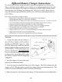
Offboard Battery Charger Instructions
The switch-mode battery charger provided is specially designed for use with your PaceSaver wheelchair. In the unlikely event of failure we recommend replacement only with
a PaceSaver brand charger. The charger is intended for use with AGM or gelcell sealed
lead-acid deep cycle discharge type batteries only. This is a 24 volt DC charger for use
only with batteries connected for 24 volt DC service. Do Not use the charger with a car
starter battery.
The PaceSaver brand battery charger includes
• Microprocessor control allows switch-mode operation for faster charging.
• Light weight and compact size offers space advantages.
• All units feature Auto Voltage Select (AVS): One unit operates for 100 VAC, 120 VAC or 230 VAC.
• Power limited battery charging (using algorithm) depending on battery state of charge.
• Automatic shutoff and restart to compensate for battery self discharge.
• Reliable charging achieved through a multi-stage, multi-mode charging algorithm.
• Thermal protection prevents damage from over temperature conditions.
• Input & output protected by automotive electronic sensor.
• Output current limit so as not to exceed the maximum power and/or thermal capacity.
• Output short circuit and reverse polarity protection.
• LEDs indicate AC Power ON, Charging Status and Fault Conditions.
Refer to the instructions provided with the battery charger for detailed specifications and operation
information.
1. Connect the plug from the charger to
the cart battery charger outlet located in
the tiller (See FIGURE 2. page 15). Align
the white mark on the connector and push
firmly in until the plug is properly seated
(See FIGURE 9). This assures proper connection to the batteries. PLEASE NOTE:
For your safety the scooter is equipped with
a charger safety lockout that will not allow
the scooter to operate while the charger plug
is plugged in.
FIGURE 9
2. Insert the charger AC power plug into a
properly wired household outlet.
3. Leave the charger on until the batteries are fully charged. This will be indicated by the
chargers L.E.D. When this point is reached, the charger will go into monitoring mode. This
mode can be left on indefinitely without any harm to the battery.
4. Before driving the scooter disconnect the charger AC Power plug from the household outlet.
-29-
5. Before driving the scooter remove the battery charger plug from the scooter connector.
6. Charts that show how long to charge a battery can be misleading. The only sure method
is to use the charger's indication of charge completion.
The charger may be left connected to the scooter batteries in monitor mode to build and
hold the charge at 100% without any damage to the batteries. Many other manufacturer's
chargers cannot be left on without a fixed time limit.
Note: The PaceSaver Battery Charger used must used according to the instructions. Failure to do so
may damage or destroy the batteries, give poor range, or be potentially dangerous. Batteries should not
be abused (for example by regularly deep discharging) and must be operated and maintained according
to the instructions.
Note: Please refer to the Batery Charger Manual included with this user manual for further instructions,
warnings and important information.
Warning: Do not disconnect batteries or open circuit the circuit breaker during charging. This is
dangerous to both people and equipment.
-30-
PaceSaver®
"Onboard Battery Charger"
Scooters equipped with the PaceSaver Onboard battery charger fully automatic battery
charger, have a 24-volt Constant Current Charger. It is designed to operate from a 120-volt
AC/ 60 Hz line source and provides a constant charging output until the batteries are fully
charged. This results in a maximum charge in a minimum amount of time. Conventional
chargers have a declining output proportionate to the charge rate of the batteries.
The PaceSaver Onboard battery charger is recommended for use with deep cycle AGM or
gel sealed lead acid batteries, and can be left "on charge" indefinitely without harm to the
batteries. Plus, the charger will operate from an AC line source as low as 100-volts and as
high as 126-volts (47-63 Hz). Circuit protection is built into the device to protect the circuitry
with reverse polarity protection and a fuse is located in the end of the charger case.
Charging Notes:
Regular use of your scooter will require regular charging. It is a common misconception that
lead-acid batteries need to be run into deep discharge before recharging. This is not true and
can lead to damage of the batteries if they are frequently discharged deeply before recharge.
Likewise, if batteries are stored for a long period of time without recharge, this may result in
permanent damage to the batteries resulting in unreliable operation and shortened battery life.
Maximum driving range of your scooter can be maintained if the batteries are fully charged
prior to a lengthy storage period. Because the charger is fully automatic it can be left connected for up to 6 months without harm to the batteries.
Fuse:
The PaceSaver Onboard battery charger is provided with an external replaceable fuse located
on the end of the charger housing. The charger is located under the rear cover of the scooter,
and on some equipment, you may need to remove the rear section from the scooter and turn
it upside down to replace the fuse.
Replace this fuse with one of an identical rating and type. Use of a fuse of a different rating
could result in a condition which could cause electrical shock potential or conditions resulting
in fire. A second fuse is located in the AC connector found on the tiller.
Service/ Troubleshooting:
Should your PaceSaver Onboard battery charger fail to perform:
1. First, check that all connections are properly made for a fully assembled scooter. On
some equipment, the charger lines go through the motor plug, so if the motor plug is disconnected for some reason, then the charger will not function. Likewise, if the batteries are
not connected, they will not receive a charge, and the meter will not give an indication.
-31-
2. Check that the wall outlet has power to it. The outlet may be on a switch and will not
function if not switched on.
3. If all connections are properly made and the unit is connected to a working outlet, check
the fuse in the charger (see Fuse section).
If these steps fail to produce satisfactory results, please refer to an authorized service
center to have the system fully analyzed.
How to Use This Charger: With the scooter
completely assembled:
1. Connect the AC power cord to the receptacle
located on the scooter tiller (See FIGURE 10),
and then to a properly grounded AC outlet (See
FIGURE 11). (refer to grounding instructions)
As a safety feature, the scooter will not operate
when the charger cord is plugged into the wall
outlet and the charger is operating.
!! CAUTION !! : Do not use connectors or
cords that are cracked, corroded or do not
make adequate electrical contact. Overheating and possible property damage may result
if defective connectors are used.
FIGURE 10
2. The LED's located on the scooter charger will
indicate that the charger is giving service to the
batteries. When fully charged, the Orange LED
will turn to green
Because this is an automatic charger, the unit
will have a constant charge rate when all is
FIGURE 11
properly connected. This will continue at a steady rate until the batteries are approximately
90% charged, at which time the charger output will drop to less than 1 ampere. The charger
will occasionally "wake up" when battery decay has fallen to below the cut-off voltage, and
the charger will provide additional charge to "top off" the batteries.
3. After charging, remove the wall cord, first from the wall, then from the cart, and store it
on the cart for future use.
-32-
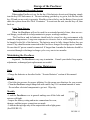
Storage of the PaceSaver
Short Term and Overnight Storage
When ending PaceSaver’s use for the day, if the batteries do not need charging, simply
turn the key OFF and remove it. The next morning, put the key in, get in, lock the seat, turn
key ON and you are ready to go again. Should you leave the key on, the Battery Saver circuit
shuts the system down after 20 to 30 minutes. To reactivate the unit, turn the key off, then
back on.
Long Term Storage
When the PaceSaver will not be used for an extended period of time, there are several things you should do to help maintain its proper working condition.
The PaceSaver and its battteries should only be stored in a dry environment with
moderate termperatures. Long term exposure to excessive hot or cold termperatures will
be harmful to the life of the batteries. The batteries must be fully charged before they are
stored. They should remain connected to the PaceSaver charger for storage up to 6 months.
Be sure that AC power remain's connected. If longer than 6 months the batteries should be
exercised through a discharge/recharge cycle every one to two months.
Maintaining the PaceSaver
In general, The PaceSaver is very easy to maintain. Consult your dealer if any repairs,
adjustments, or damaged part replacements are needed.
Routine Maintenance
Daily
- Charge the batteries as described in the “Scooter Batteries” section of this manual.
Weekly
- Check the tire pressure for proper inflation. See the proper specifications for your scooter.
- Clean the PaceSaver using a damp cloth with a mild soap. Use a minimal amount of water.
Do not allow electrical components to get wet. Wipe dry.
Monthly
- Look the PaceSaver over in general making sure all the bolts and
nuts are still tight.
- Inspect the battery wiring and motor connections for wear,
damage, and that proper connections are made.
- Lubricate the top edge only of the seatpost tube with a light grease
(See FIGURE 12).
FIGURE 12
-33-
Twice a Year
- Inspect all wheels for looseness and tire wear.
- Clean the upholstery as needed.
Yearly
- Thoroughly examine your scooter to look for undetected wear and other potential problems
and have problems repaired immediately. The expense involved is always less than repair
bills caused by a lack of proper maintenance. In the same way a car would not last forever
without service, a scooter should be maintained regularly.
AND REMEMBER! If you ever notice any part of your PaceSaver scooter working in an
improper or unsafe manner, stop riding it immediately and contact your dealer to arrange
repairs. Do not use your scooter if there is a possibility it is not safe!
Lubrication
Owners of scooters that are supplied with this manual do not need to lubricate their
drive system. It is sealed and permanently lubricated.
SEAT LOCK
The seat lock usually requires no adjustment, and will provide years of trouble free
service. However, as time passes and surfaces begin to wear, you may need to remove
one of the spacer washers (see exploded view) in order to tighten up the tolerances. To do
this you need not remove the seatlock from the seatpost. First turn the seat upside down on
a level surface and remove one of the two
1/4"-20 Bolts that hold the seatlock together. Then
remove a washer that lies between the two halves
of the seatlock ( this may leave one side with more
washers than the other , that’s O.K.). Be sure to
reassemble the seatlock in exactly the same way it
was disassembled and with all components in the
proper place. If the seat lock works properly but still
does not securely tighten the seat, another washer
may be removed (this time from the opposite side).
If it still operates incorrectly, contact your dealer
immediately (See FIGURE 13).
FIGURE 13
-34-
Tires
The recommended pressure for the tires is listed below. MAKE SURE that you are
using the specification for the STYLE PaceSaver that you own. Be careful not to overinflate. Properly inflated tires aid in the PaceSaver’s efficiency. Under-inflated tires require
more energy to roll, thus decreasing scooter performance. Under-inflated tires also affect the
PaceSaver stability. A “soft” tire on one side, for example, can lead to overturning during
cornering (under certain circumstances). Flat free tires are available if you are unable to
check your tire pressure.
ALL THREE WHEELED SCOOTERS
50 PSI / 344.74 KPA
Front & Rear
ALL FOUR WHEELED SCOOTERS
30 PSI / 206.84 KPA - 50 PSI / 344.74 KPA
Front
Rear
Warning
DO NOT disassemble any wheel at any time for repairs while still inflated as the pressure may blow wheel rims apart while you are loosening them and serious injury may result.
Completely deflate the tire first.
FOUR WHEELED FRONT ENDS
The PaceSaver four wheeled scooters have a front suspension system not unlike a cars. The Eclipse models are
adjustable but the mechanism should be worked on by a
professional. Should you feel that there is a problem with
the steering and suspension, please contact your dealer.
Otherwise the front end should be inspected yearly by a
qualified PaceSaver service center.
-35-
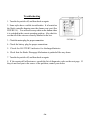
Troubleshooting
1. Turn the keyswitch off, and then back on again.
2. Some styles have a visible circuit breaker. It is located on
the black controller housing near the chrome seat post (See
FIGURE 14). You will not see any white on the button when
it is switched in the correct operating position. Also check to
see that all of the wires are securely attached to the box.
3. Check the motor plug for proper connection.
FIGURE 14
4. Check the battery plug for proper connections.
5. Check the BATTERY indicator for discharged batteries.
6. Check that the Brake Disengage Mechanism is pushed all the way down.
7. Turn the keyswitch off, and then back on again.
8. If the scooter still will not move, consult the list of diagnostic codes on the next page. If
they do not lead you to the source of the problem, contact your dealer.
-36-
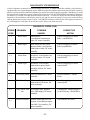
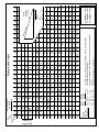
DIAGNOSTIC INFORMATION
Leisure Lift products are known for excellent reliability and service. To further enhance this capability, your PaceSaver is
equipped with a state of the art diagnostic system. While the system does indicate basic areas the user can check, it's primary
purpose is to help your dealer identify the problem to get your scooter repaired as quickly as possible. When the key is on and
the system detects a problem, the scooter will not run or will shut down. The BATTERY METER will MOVE continuously
for about five (5) seconds. It will then proceed to flash a 2 part code. You may also depress the horn button during this
diagnostic cycle and the horn will beep the codes in sync with the meter movement. Use the codes on the following
chart to determine the proper corrective action. If the METER continues to MOVE after following the procedures in
the LED Diagnostic Code chart, do not ride the scooter. Notify your dealer for repair.
DIAGNOSTIC CODES (1108)
ERROR
CODE
PROBLEM
POSSIBLE
CAUSES
CORRECTIVE
ACTION
1-1
Brake Short
Shorted brake,
Loose/broken connection to
brake, DC motor controller
Check wiring/plugs to motor/
brake - consult dealer
1-2
Brake Open
Brake shorted to case, Missing/open brake, Loose/broken
connection to brake, DC motor
controller
Check wiring/plug to motor/
brake-consult dealer
2-1
Motor Short
Bad motor, Loose/broken connection to motor, DC motor
controller
Check wiring/plugs to motorconsult dealer
2-2
Motor Open
Bad motor, Loose/broken
connection to motor, Brake
manually released, DC motor
controller
Check wiring/plugs to motorconsult dealer
2-3
2-4
4-2
5-3
Power Relay Short Defective batteries, DC motor
controller
PSL Motor Short
PSL motor, Loose/broken
connection to PSL motor, DC
motor controller
Charge Mode Time Bad charger cable, Bad batteries, Bad charger, DC motor
Out
controller
Throttle Failband
Throttle control pot is off center/open, Loose/broken connection/cable, User interface, DC
motor controller
-37-
Load test batteries - consult
dealer
Check wiring/plugs to motor consult dealer
Charging unit, charger plugged
in, check wiring - consult dealer
Check throttle for center
Commonly Asked Questions and Possible Answers
Why has there been a loss of power?
1. Undercharged batteries. Check the BATTERY meter. The BATTERY meter indicates the charge condition of the batteries while you are driving. (The meter does not
indicate the “true condition” while sitting still.) If, while you are driving, the meter
needle falls into the yellow or red area, charge the batteries as soon as possible. Charging will bring batteries up to full charge.
2. The Posi-Lock Brake may not be releasing. This malfunction means the motor
must overpower the brake to move, which requires a great deal of power. A rubbing
sound can be heard during this type of malfunction.
3. Under-inflated tires. Check for proper inflation (check the specifications for your
particular scooter).
4. Excessive weight on the cart. Remember that the PaceSaver takes a maximum of
300 Lbs.
- Plus III Premier & Espree Premier
350 Lbs.
- Plus III Titan, Espree Titan & Eclipse Premier
450 Lbs.
- Eclipse Atlas, Espree Atlas & Plus III Atlas
500 Lbs.
- Eclipse Atlas 5 & Espree Atlas 5
5. There may be other motor or driving mechanism malfunctions. Consult with
your dealer.
Is there a way to stop the cart, or apply the brakes, if the Brake Disengage Mechanism is out?
NO! THE BRAKE DISENGAGE MECHANISM DEFEATS COMPLETE BRAKING. Never
sit on or ride the scooter in this situation! When pushing the unit, the "push-to-fast" system
limits the speed should you loose control pushing down a hill.
Will leaving the batteries unused for a long time damage them?
Yes. Storage of batteries is very important to their life span. The very best way
to maximize battery life is to store them in a fully charged condition in a cool place. Then
periodically ( at least every 1-2 months!) charge to keep the batteries in this full charge condition. Do not store in cold or freezing temperatures. Batteries should never be subjected to
freezing temperatures. Undercharged batteries can be ruined quickly in freezing conditions.
Can a regular liquid lead-acid battery be used, like in a car?
No. A DEEP CYCLE battery must be used. A car battery is not intended for deep
-38-
cycle operation. A car battery would be ruined within a few days of operation in the scooter.
Deep cycle batteries are available in both AGM sealed lead-acid and gel cell lead-acid. Either type can be used. These batteries are maintenance free and have no danger of spillage.
Some are also approved by the Federal Aviation Administration for air travel. Do not use a
conventional liquid flooded cell lead-acid deep cycle battery. Spillage of the battery acid
can cause severe burns and will damage many components of your PaceSaver. The charger
which came with the PaceSaver is designed specifically to charge AGM or gel cell batteries.
Why will my PaceSaver not climb an incline?
1. Excessive weight on the scooter for the grade of the incline. Refer to the Ramp Incline
Chart in this Owner’s Manual.
2. Batteries not fully charged, or are bad. Charge them and have them tested.
3. Under-inflated tires.
4. Attempting to go up the incline in reverse. Remember, there is a forty percent (40%)
reduction in speed when moving in the reverse direction.
Thank you for your purchase of a PaceSaver scooter. We hope that you will enjoy
many years of trouble free service and freedom on your new scooter. Remember,
your investment and your safety depend upon following the guidelines and suggestions contained in this manual.
-39-
Ramp Rise
(In Inches)
5
6
7
9.5 6.5
8
4"
5"
6" 14.5 9.5
7"
5
8" 19.5 12.8 9.5 7.5 6.5 5.5
17.5 14.5 12.5 11 9.5 8.5
18"
RAMP
INCLINE
EXAMPLES
42"
35"
12"
12"
12"
12"
12"
per
per
per
per
per
3'
5'
7'
9'
12'
=
=
=
=
=
19.5o
11.5o
8o
6.5o
4.5o
3
4
8
6
5.5
7.5
12
8.5
6.5
6
8
6
5.5
5
11 10.5 10
9
7
6
4
4.5 4.5
4
5.5 5.5
5
3
2
3.5 3.5
3
2.5
2
4
6.5
5
4.5
4
6
5
4
4
9
8.5 8.5 7.5
7
5.5
5
3
3.5 3.5
11 10.5 10
9
7.5
6
5
4.5 4.5
4
3.5 3.5
3
2.5 2.5
3
3
2
gth
Len
2.5 2.5
R
i
s
e
Incline (Max for vehicles) - (NY State Max. Recommended Ratio)
Incline (Maximum for buildings)
Incline (Acceptable Private Residence for power/manual chair w/help)
Incline
Incline (Gov't Standard - Pub. Bldg.)
18.5 17 15.5 14.5 13.5 12.5 12
13
4
4.5 4.5
4
7.5 6.5
6.5
6
5
3
2.5
2
3.5 3.5
11 10.5 9.5
9
8
7
6.5
5.5
4.5 4.5
4
3
3
2.5 2.5
2
3.5 3.5
18.9 17 15.5 14
15 13.5 12
19.5 17
9.5 8.5
28"
11
12 10.5 9.5
12
13
14
11
6
5
15
Ramp
Length
6.5 5.5
9.5 8.5 7.5 6.5
7
22"
Ramp
Rise
15.5 13
16"
16
8
17 13.5 11
14"
20"
7
9.5 8.5 7.5
8
19.5 14.5 11.5 9.5
5.5 4.5 4.5
12"
6
7
8
4
12 9.5
4.5
16
5
3
3.5 3.5
3
10"
5.5
2
Ram
p
3
6.5
5
4
3.5
3
2.5
6.5
5.5
9 degrees = 16%
12 degrees = 22%
15 degrees = 27%
7
6
4.5 4.5
4
3.5 3.5
3
2.5 2.5 2.5
8.5 7.5
7
5.5
4.5
4
3.5
3
2.5 2.5
SYMBOL KEY
Inches
(")
Feet
(')
Degree (o)
28' 30'
Incline
(degrees
of slope)
12' 13' 14' 15' 16' 17' 18' 19' 20' 22' 24' 26'
2.5 2.5
7
4
4
3
22 14.5 11 8.5
4
3.5
3
2
11'
9"
6
4
5
11
8.5 6.5 5.5
17
3.5
4
2.5 2.5
3
2
10'
2
1.5
9'
Ramp Incline Chart
2.5
2
8'
5
3.5
3
2
7'
5.5
3
2.5
6'
4
3.5
3
5'
4.5
12
4
5
7
4'
3"
3'
Ramp Length
(In Feet)
2'
r
In of ee
cl
in
e
eg
D
-40-
Addendum
All "ATLAS" Models
PLEASE READ THE FOLLOWING INSTRUCTIONS CAREFULLY!
THIS INFORMATION ONLY APPLIES TO ATLAS SCOOTER MODELS
SEAT POST ADJUSTMENT
While the seat post adjustment works much the same as shown in your manual (Refer
to seat assembly operation section in this manual for more information), there are some extra
components used on the ATLAS for increased support. Please look at the drawing to the
right and note the extra bracket that surrounds the seat post (part 22) and the small plastic
insert that goes inside the seat post (part 21). If your unit
is ever disassembled for any reason, please make sure these
components are replaced as shown in the drawing.
ANTI-TIP WHEELS
The ATLAS three wheeler comes equipped with
front Anti-Tip wheels for additional safety (see part # 20 on
FIGURE 15). DO NOT, under any circumstances, remove
these Anti-Tip wheels. They are a required safety feature of
the scooter and it should not be operated without them. If
they cause a problem while maneuvering the scooter under
certain circumstances, that should be your indication that
the scooter should not be used in that manner!
RAMP ANGLES
The ATLAS is rated for maximum 500 lbs rider on
o
a 8 incline (14%) and should not be used on ramps steeper
than that for safety reasons. If you do not know the exact
angle of an incline you intend to traverse, please ask your
dealer or some other individual to find out the degree of
incline for you before using the scooter on that incline.
FIGURE 15
-41-
Throttle Operated Power Seat Instructions
CAUTION: Only drive the scooter when the power seat is in the lowest position to avoid tipping.
RAISING AND LOWERING THE SEAT
1.
Position the DRIVE/SEAT switch to SEAT. A green LED will light up (See FIGURE 16).
IMPORTANT: Do not change the drive/seat switch position during operation (Doing so will cause the scooter to come to an abrubt stop). After releasing the
throttle, wait two seconds for the controls to completely cycle off before changing the
Drive/Seat switch or turning the key off. If the Drive/Seat switch is changed to the
seat position while driving, the scooter will stop quickly. If the switch is changed to
the drive position while running the seat or the key is turned off (before the controls
have finished cycling) the scooter will move a few inches. Always wait the two seconds between operations.
~ BE SURE those around you do not unexpectedly operate the switch. ~
2.
To raise the seat, depress the throttle bar in the FORWARD position.
Note 1: The seat motor will react just like the cart motor. The more pressure
you put on the throttle bar the faster you go up.
Note 2: The speed adjustment knob position effects the speed of the seat motor.
The fastest speed setting is 10.
3.
To lower the seat depress the throttle bar to the REVERSE position.
Notes 1 & 2 apply.
RESUMING TO DRIVE MODE
1.
Your scooter is equipped with a safety sensor that will prevent you from driving
if the power seat is raised more than 1” or it is swiveled sideways. If either of these two
conditions occur, the seat motor LED on the throttle will be lit even if the selector on the
throttle is set to “Drive”. The light will go off once you lower the seat and/or rotate it forward and wait 2 seconds after releasing the throttle.
Seat Motor
Indicator LED
2.
Make sure the seat is within an inch
of its lowest position.
3.
Make sure the swivel seat is facing
forward and is locked into place by the
handle on the side of the seat. CAUTION:
Failure to have the seat facing forward
while driving could cause the safety sensor
discussed above to become activated
bringing the scooter to an abrupt stop.
Speed
Control
Knob
Seat
Drive
5
10
1
LOW
FULL
FIGURE 16. (RIGHT HAND THROTTLE)
4.
After the seat has been lowered and
locked facing forward, wait two seconds, position the DRIVE/SEAT switch on the throttle
to DRIVE and proceed with normal operation.
-42-
EFFECTIVE DECEMBER 2, 1994 THE FEDERAL GOVERNMENT REQUIRES THIS STATEMENT TO BE INCLUDED.
ELECTROMAGNETIC INTERFERENCE
CAUTION: IT IS VERY IMPORTANT THAT YOU READ THIS INFORMATION REGARDING
THE POSSIBLE EFFECTS OF ELECTROMAGNETIC INTERFERENCE ON YOUR POWERED WHEELCHAIR / POWERED SCOOTER.
Electromagnetic Interference (EMI) From Radio Wave Sources
Powered wheelchairs and powered scooters (in this text, both will be referred to as powered wheelchairs)
may be susceptible to electromagnetic interference (EMI), which is interfering to electromagnetic energy
(EM) emitted from sources such as radio stations, TV stations, amateur radio (HAM) transmitters, two-way
radios, and cellular phones. The interference (from radio wave sources) can cause the powered wheelchair
to release its brakes, move by itself, or move in unintended directions. It can also permanently damage the
powered wheelchair's control system. The intensity of the interfering EM energy can be measured in volts
per meter (v/m). Each powered wheelchair can resist EMI up to a certain intensity. This is called its "immunity level." The higher the immunity level, the greater the protection. At this time, current technology is
capable of achieving at least a 20 v/m immunity level, which would provide useful protection from the more
common sources of radiated EMI.
There are a number of sources of relatively intense electromagnetic fields in the everyday environment.
Some of these sources are obvious and easy to avoid. Others are not apparent and exposure is unavoidable.
However, we believe that by following the warnings listed below, your risk to EMI will be minimized.
The sources of radiated EMI can be broadly classified into three types:
1) Hand-held portable transceivers (transmitters-receivers) with the antenna mounted directly
on the transmitting unit. Examples include: citizens band (CB) radios, "walkie talkie," security, fire, and police transceivers, cellular telephones, and other personal communication
devices. **NOTE: Some cellular telephones and similar devices transmit signals while they
are ON, even while not being used;
2) Medium-range mobile transceivers, such as those used in police cars, fire trucks, ambulances,
and taxis. These usually have the antenna mounted on the outside of the vehicle; and
3) Long-range transmitters and transceivers, such as commercial broadcast transmitters (radio
and TV broadcast antenna towers) and amateur (HAM) radios.
NOTE: Other types of hand-held devices, such as cordless phones, laptop computers, AM/FM radios, TV
sets, CD players, and cassette players, and small appliances, such as electric shavers and hair dryers, so far
as we know, are not likely to cause EMI problems to your powered wheelchair.
-43-
Powered Wheelchair / Scooter Electromagnetic Interference (EMI)
Because EM energy rapidly becomes more intense as one moves closer to the transmitting antenna (source),
the EM fields from hand -held radio wave sources (transceivers are of special concern). It is possible to
unintentionally bring high levels of EM energy very close to the powered wheelchair's / scooter's control
system while using these devices. This can affect powered wheelchair movement and braking. Therefore,
the warnings listed below are recommended to prevent possible interference with the control system of the
powered wheelchair.
WARNINGS
Electromagnetic interference (EMI) from sources such as radio and TV stations, amateur radio (HAM)
transmitters, two-way radios, and cellular phones can affect powered wheelchairs. Following the warnings
listed below should reduce the chance of unintended brake release or powered wheelchair movement which
could result in serious injury.
1) Do not operate hand-held transceivers (transmitters-receivers), such as citizens band (CB)
radios, or turn ON personal communications devices, such as cellular phones, while the powered
wheel-chair is turned ON;
2) Be aware of nearby transmitters, such as radio or TV stations, and try to avoid coming close to
them;
3) If unintended movement or brake release occurs, turn the powered wheelchair OFF as
soon as it is safe;
4) Be aware that adding accessories or components, or modifying the powered wheelchair, may
make it more susceptible to EMI (Note: There is no easy way to evaluate their effect on the
overall immunity of the powered wheelchair / scooter);
5) Report all incidents of unintended movement or brake release to the powered
wheelchair manufacturer, and note whether there is a source of EMI nearby.
Important Information
1)
20 volts per meter (v/m) is a generally achievable and useful immunity level against EMI
(as of May 1994) (the higher the level, the greater the protection).
2)
This model of PaceSaver vehicle has a minimum immunity level of 20 volts per meter
(20 v/m).
3)
The immunity level of this model PaceSaver vehicle is unknown.
-44-
Dear Friend:
Thank you so much for your purchase of a PaceSaver Scooter! We value your trust in us and we will do
everything we can to keep you happy. You're in a special group now. Thousands of people before you have trusted
Leisure-Lift to provide them with the highest quality mobility products available. They and you have made PaceSaver the most valuable scooter.
We hope that you have read the Owners Manual completely, and that you understand all of the safety
precautions and recommendations that apply to your particular scooter. If you have any questions, please ask you
PaceSaver dealer. They can help explain any points that you do not understand.
In addition, your dealer will be glad to help you with any of your other PaceSaver needs. Situated close to
you, they are in the best position to provide you with assistance and service.
The enclosed warranty card must be filled out in order for Leisure-Lift to:
1. effectively warranty your product in case of a problem
2. to properly follow the guidelines laid down by the Food & Drug Administration and to
3. allow us to locate you in the event of a product recall or modification
We also ask several questions about you to help us better understand the needs of our customers. The information you provide us helps to keep our scooters at the leading edge of quality and functionality and we hope that
we can count on you to help us. Leisure-Lift always values the options of our customers and you may write us at
any time to relate to us your "PaceSaver Experience" good (or not so good).
REMEMBER. . . It is in your best interest to see that you (not your dealer) properly complete this card
and see that it is returned to Leisure-Lift.
Leisure-Lift®, PaceSaver® and Titan® are registered trademarks. Espree™, Eclipse™, Junior™, Premier™, Plus III™, Soft-Touch™,
Com-For-Back™, and Atlas™ are all trademarks of Leisure-Lift®, Inc.
© 2005 Leisure-Lift®, Inc. All rights reserved.
PaceSaver LIMITED WARRANTY
Leisure-Lift, Inc. warrants, to the original PURCHASER, or to the DEALER, that each new PaceSaver will be free from
defects in material and workmanship under normal use and service for a period of . . .
THREE YEARS -on the front & rear steel base frame. - on the PaceSaver Premier's transaxle (Premier's only)
ONE YEAR FROM date of purchase, or 15 MONTHS from date of shipment from the factory, whichever is shorter, on component parts.
SIX MONTHS on batteries purchased from Leisure-Lift, Inc. (Many dealers supply their own batteries.
No warranties will be extended by Leisure - Lift, Inc. on these batteries.
PaceSaver Premier series Transaxles have a FIVE YEAR LIMITED parts warranty
(Parts cost only) Year one - 100% motor, brake & transaxle, Year two - 50% motor, brake & transaxle and
Years three thur five - 50% transaxle
All parts that are defective, as determined by the factory, will be replaced free of charge within the warranty period (see above
warranty for details. This Warranty from Leisure-Lift DOES NOT INCLUDE LABOR., either at your home or at your dealer's place of
business. During the warranty period, Leisure-Lift, Inc. may, at it’s discretion, determine it is necessary to return the PaceSaver to the
factory for repair. Leisure-Lift, Inc. will provide parts and labor free of charge for problems considered to be covered under our warranty.
The customer is responsible for all freight charges including scooter shipped to the factory.
Failure to properly service the scooter at the intervals prescribed by the owners manual, abuse or faulty service may void this
limited warranty and can result in charges for parts and service. All rights under this limited warranty must be exercised within 20 days
after the end of the warranty. This warranty does not apply to any PaceSaver that meets any of the following conditions and Leisure-Lift,
Inc. is not responsible for accidents or damage caused by:
1.) Abuse or misuse of the vehicle,
2.) Use of the scooter by any individual over the prescribed weight limit.
3.) Commercial use, this includes scooter rental.
4.) Parts which become defective , worn, damaged or broken due to
A.) The use of replacement parts not supplied by Leisure-Lift, Inc.
B.) Servicing by anyone not authorized by Leisure-Lift, Inc
C.) Electrical or mechanical modifications of the scooter by other than Leisure-Lift, Inc.
NOTE; DISASSEMBLING, MODIFYING AND/OR TAMPERING IN ANY UNAUTHORIZED MANNER WITH THE SCOOTER
WILL VOID THE WARRANTY. Leisure-Lift, Inc. reserves the right to make engineering changes, additions, or improvements upon its
current product without obligation to install the same upon its products previously manufactured.
Leisure-Lift, Inc.
Warranty revision date January 1994
1800 Merriam Lane
www.PaceSaver.com
-45-
Kansas City, KS 66106
PAT. NO 4,570,739
PaceSaver Extended Limited Warranty
Qualifications and Guidelines
This is your guide to receiving the benefits of Leisure-Lift’s Extended Limited Warranty coverage. Read it carefully and follow all instructions!
The Leisure-Lift company will extend the following EXTENDED LIMITED WARRANTY provisions to qualified owners
of PaceSaver vehicles manufactured after January 1, 1994.
The EXTENDED LIMITED WARRANTY is defined as the following:
A “LIFETIME” Warranty on your frame components (consult your dealer for specific components).
A “TWO YEAR” prorated Parts Warranty.
One year parts replacement at no charge (100%) parts replacement.
Second year parts replacement at half off (50%) of current retail parts prices on parts covered under this warranty.
This warranty DOES NOT include labor or transportation cost either to your dealer or back to Leisure-Lift. Regular labor charges apply.
EXTENDED WARRANTY NO COST TO YOU: A One Hundred Dollar Retail Value.
HOW TO ENROLL:
You must fill out and return the “EXTENDED WARRANTY REGISTRATION” form in the envelope in which you received this form within
15 days of purchase (date on receipt). You must include in the envelope a copy of your proof of purchase (receipt, etc) to Leisure-Lift. You
will then receive your official EXTENDED LIMITED WARRANTY CERTIFICATE”.
TERMS AND CONDITIONS
You must be in possession of an EXTENDED WARRANTY CERTIFICATE from Leisure-Lift in order to receive coverage under LeisureLift’s extended warranty program. IF YOU DO NOT RECEIVE YOUR CERTIFICATE WITHIN 30 DAYS OF SUBMITTING YOUR REGISTRATION AND PROOF OF PURCHASE, CONTACT THE DEALERSHIP FROM WHICH YOU PURCHASED YOUR SCOOTER AND
HAVE THEM CONTACT Leisure-Lift. If Leisure-Lift did not receive your original registration and proof of purchase you will be required to
resubmit proof of purchase. Warranty is not transferable.
All other terms and conditions of Leisure-Lift’s regular PaceSaver warranty apply.
Failure to return a completed registration form within the time limits will void this offer.
Cut along dotted line
Yes, I want to register my warranty and apply for my
For Service Call
“EXTENDED LIMITED WARRANTY”!
Dealer:
I have
1. Enclosed my proof of purchase and
2. Completely filled out the registration information below.
Please send me my Warranty Certificate by return mail. I understand that I must have the
certificate to receive extended coverage and that if I do not receive my warranty certificate
within 30 days, I should contact the dealership from whom I purchased the unit.
DEALER NAME (if different from above)______________________
Your Serial Number is:
This Warranty has been sponsored by my dealer
YOUR NAME ____________________________________________
ADD1
City, St,:
YES, please send me my Extended Warranty Certificate.
I certify that I have read and understand the owners
manual and all of the safety information contained within.
(sign)
_________________________________________________
ADD2 ___________________________________________________
CITY, ST, ZIP ____________________________________________
To help us better understand our customers, we would like to know a
little about you. Please fill in all the information you can.
PHONE______/____________________ Date Purchased __/__/___
AGE:______ WEIGHT: _____________ HEIGHT:___________
-46-