1
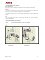
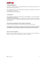
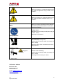
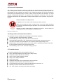
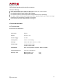
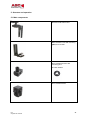
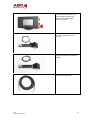
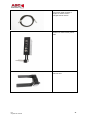
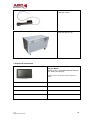
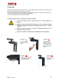
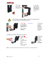
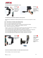
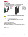
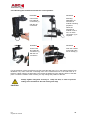
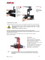
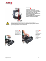
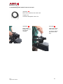
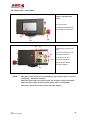
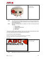
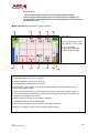
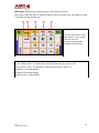
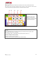
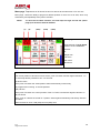
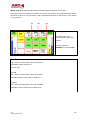
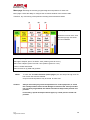
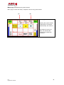
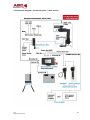
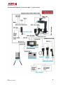
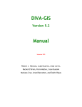
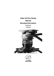
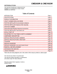
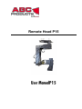
Remote Head P15 Remote Head P15 Date of issue : 2011 /08 P15 Original user manual 2 TABLE OF CONTENTS 1. Page Equipment Information 4 1.1 Contents of 2-axis unit and options 4 1.1a Additional contents of 3-axis unit and options 5 1.2 Responsibilities of the manufacturer / EC declaration of conformity 6 1.3 Responsibilities of the operator 7 1.4 Exploded drawing with spare part numbers 7 1.5 External interfaces 8 1.6 Legal notice 8 User manual 9 2.1 To understand the user manual correctly 9 2.1.1 Marking on the unit 9 2.1.2 Markings in this user manual 10 2.2 Service address 11 Safety precautions 11 3.1 General safety precautions - manufacturer 11 3.2 General safety precautions - Use 12 3.3 General safety precautions - Check 12 3.4 Intended use of P15 12 3.5 Personnel requirements 13 3.6 Safety-related environmental conditions 13 3.7 Possible misuse 13 3.8 Residual hazards and protective measures 14 Technical information 14 Technical data 14 Structure and operation 15 5.1 Main components 15 5.2 Optional accessories 18 5.3 Mounting 19 5.3.1 Mounting P15 2 axes / Base frame with drive module 19 5.3.2 Mounting of P15 2-axis / Mounting of camera plate 19 5.3.3 Mounting the power cable BUS for 2-axis 21 5.3.4 Mounting of box zoom/focus module for 2-axis operation 21 5.3.5 Mounting of P15 3-axis 23 5.3.6 Mounting the power cable BUS for 3-axis installation 23 5.3.7 Mounting the zoom/ focus module for 3-axis operation 24 5.3.8 Mounting of the camera 25 5.3.9 Attaching main control cable 27 2. 3. 4. 4.1 5. P15 Original user manual 3 5.4 5.4.1 Control unit - Touch panel 28 Control unit – Touch panel operation 29 5.5 Schematic diagram -Connection plan - 2-axis version 37 5.6 Schematic diagram - Connection plan - 3-axis version 38 6. Care of the remote heads 40 7. General notes and safety information on operation 40 P15 Original user manual 4 1. Equipment Information 1.1 Contents of 2-axis unit 1. 1 x Touch panel O 2. 1 x Base frame O 3. 1 x Drive module pan-axis with mounting pins and lock washer O 4. 1 x Drive module tilt Axis O 5. 1 x L-handle with base plate O 6. 2 x 3/8“ long attachment bolts O 7. 1 x Box (Zoom/Focus/Power) O 8. Cable set Bus for 2 – Axis version O 9. Set of 1 x Cable Zoom/ Focus Fujinon O 10. 1 x Cable set Zoom/Focus Canon O 11. 1 x Cable set Zoom/Focus Canon Digital O 12. 1 x Cable set Zoom/Focus Angenieux O 13. 1 x set Allen wrench 14. 1 x Main control cable Bus 20m O 15. 1x Double battery adapter V-Mount O 16. 1 x User manual O 17. 1x Monitor holder with ¼“ bolts O 18. 1x AC Adapter 24V O P15 Original user manual 5 1.1a Additional contents of 3-axis unit 1. 1 x Drive module roll axis O 2. 1 x Cable bus O 3. 1 x L- handle with base plate O 4. 2 x Attachment bolts 3/8“ long O Controls 5. One-man control consisting of: 1 x Attachment bar with Tripod inclusion O 1 x Zoom/Focus handle O 1 x Joystick handle O 6. 1 x Holder with rocker 3. axis O 7. 1 x Panel with joystick, zoom, focus O 8. 1 x PanBar cable set O 9. Case for 2/3 axis version O 10. User manual O 11. C-stand for one-man operation O 12. Panel joystick O O O Packed on (Date): Signature : _________________________ __________________________________________________ P15 Original user manual 6 1.2 Responsibilities of the manufacturer / EC declaration of conformity EC declaration of conformity for machinery directive 2006/42/EC Annex II 1.A The manufacturer / distributor MovieTech AG Martin-Kollar-Str. 9 D-81829 Munich hereby explains, that the following product Product name: P15 Manufacturer: ABC products Serial number: Series/ type name: Remote head product Description: P15 is a product for the photography and film industry developed to allow weightless camera movements. It conforms to all relevant regulations of the above-mentioned directive and the other applied directives (following) – including any current changes thereof at the time of declaration. The following harmonized standards were applied: EN ISO 12100-1:2003 EN ISO 12100-2:2003 EN ISO 14121-1:2007 Safety of machinery - Basic concepts, general principles for design - Part 1: Basic terminology, methodology (ISO 121001:2003) Safety of machinery - Basic concepts, general principles for design - Part 2: technical principles (ISO 12100-2:2003) Safety of machinery - risk evaluation - Part 1: principles (ISO 14121-1:2007) The following national or international standards (or parts/clauses thereof) and specifications were applied: Name and address of the person authorized to compile the technical documentation: Mr. Sigfried Käser Mr. F. Strassmann Place: Munich Date: 16.06.2011 P15 Original user manual 7 1.3 Responsibilities of the operator Repair requirements Repair of the P15 is only permitted by the MovieTech AG or authorized contract partners. Disposal P15 should not be disposed of in domestic waste. It must be disposed of at a collection site (please check with your municipality) or through your dealer/manufacturer. The recipient address is given on the product label. This provides for an environmental friendly disposal. Care It is recommended to clean P15 with a damp, clean cloth when dirty. Avoid any caustic or corrosive cleaning agents. 1.4 Exploded drawing with numbering Use the indicated numbers to order any spare parts! Note P15 3- axis version P15 Original user manual 2-axis version 8 1.5 External interfaces P15 may be mounted hanging or standing (upside down) at a sufficiently stable carrier unit suitable for the load (crane or dolly). P15 is equipped with a euro mount adapter (80mm outer diameter) for attachment to film devices such as dollies or camera cranes. A Mitchell adapter is optionally available. 1.6 Legal Notice The manufacturer’s specified limit values must be strictly adhered to. Any excess should be avoided under all circumstances. In case of accidents due to negligence or abusive use, the manufacturer will not be held liable for any damage or injuries. The assembly and disassembly sequence specified in the user manual must be observed. Use exclusively original parts for the product’s maintenance. Accessories of other manufacturer, may limit neither the use nor the safe use of P15! The people entrusted to operate P15, must have read and understood the original user manual of the manufacturer. In case of questions regarding the safe use, please contact the manufacturer. Contact details may be found among other things on the CE marking on the P15 touch panel. Service life of the equipment: Service life span is limited by material wear and tear. Therefore, service life depends on frequency of use and environmental conditions, to which P15 is exposed. P15 Original user manual 9 2. User manual Thank you for choosing P15, we are thankful for your confidence. P15 allows gliding camera movements in horizontal and vertical directions. We wish you much joy and success with your new ABC products P15! Your P15 has the following main features: - quiet propulsion system - direct access to programming - sliders for data, thus 360° swing radius on all axes - Short assembly and disassembly times Read this user manual carefully before you use your new equipment for the first time. It contains all the information you need to know on the unit operation, so that you avoid personal injury and property damage. Carefully observe all safety instructions in this user manual. Keep this user manual carefully. Give this user manual to the new owner, if you sell or otherwise leave the unit. Inform more users on the necessity of reading and understanding the user manual before the first use. 2.1 To understand the user manual correctly 2.1.1 Marking on the unit CE mark: This mark means that your equipment meets the safety requirements of all applicable EU directives Dustbin: This sign means that you must dispose of the unit only at a local collection site 2.1.2 Markings in this user manual Marking Meaning Draws your attention on the handling and effect of safety information. P15 Original user manual 10 Makes you aware of a dangerous situation that can cause you significant injury or death, if not avoided. WARNING Makes you aware of a dangerous situation that can cause you mild to moderate injury, if not avoided. CAUTION Makes you aware of potential property damage and other important information in connection with your equipment. NOTE Safety shoes: Mandatory sign according to ANSI (according to Z 535.3 - 2007) Meaning: Foot protection Foot protection Fall down/drop: Falling down Warning sign according to ANSI (according to Z 535.3 - 2007) Meaning: Falling down / downward movement – danger to feet Danger of Crushing Bruise/ crush: Crushing Warning sign according to ANSI (according to Z 535.3 - 2007) Meaning: Risk of crushing for hands 2.2 Service address MovieTech AG Martin-Kollar-Str. 9 D-81829 Munich E-mail: [email protected] www.movietech.de Tel.: +49 (0) 89 43 68 91 3 P15 Original user manual 11 3. Safety precautions 3.1 General safety precautions - manufacturer Before commissioning, ensure that you have read and understood the user manual. Do not leave the assembled remote head unattended. Secure against unauthorized use. The manufacturer’s specified limit values must be strictly adhered to. Any excess should be avoided under all circumstances. The remote head may not be assembled under the influence of alcohol, drugs or other narcotics. Only qualified persons may be assigned with the assembly and disassembly and operation of the remote head. If necessary, the assignment must be stated in writing. Beware of possible bruising during assembly and disassembly and during operation (please see chapter structure and special warnings for each operating phase). Warning labels on the product and the manual must be observed! Ensure and guarantee the safe fixing of a camera on the remote head before each use. Use additional straps for safe fixing. Electrical equipment like monitors, must always be protected against moisture and humidity. Never move the remote head mechanically by hand when switched on! P15 Original user manual 12 3.2 General safety precautions - Use Follow the instructions on the use of maximum 25 kg camera weight in the 2-axis operation, 15kg camera weight in the 3-axis operation. Note warnings on the unit, special instructions on stability and safe use. Do not leave the assembled P15 unattended. Secure against unauthorized use. Because of the danger of a lightning strike, adjust the operation when a storm approaches. P15 may be used at an ambient temperature of -5 - +40°C. Do not assemble and disassemble, if the maximal permissible wind velocity exceeds 50 km/h. P15 is suited for studio and limited outdoor use. Avoid installing in a sandy, dusty, wet and salty environment. Avoid dashing the remote heads against any objects and obstacles, because of possible damages to materials and the drive. Damaged parts, above all safety-related parts, must be replaced by the manufacturer. 3.3 General safety precautions - check Before each use, safety must be checked during operation by visual and functional testing (according to DIN15999) In particular, pay attention to the following criteria unusual noises during movement, deformations (e.g. bending, twisting), damage (e.g. cracks, corrosion), missing parts (e.g. retaining pins, fasteners) defective clamp functions of the adjustment mechanisms defective cables In case of form changes or damages, contact the manufacturer! Please observe all other safety instructions in the following chapters! 3.4 Intended use of P15 P15 may only be used according to its “intended use”. P15 is designed for horizontal and vertical camera movements around the pivot point of the middle section. Therefore, the camera thereby must weigh between 0.5 and 25kg (15kg in the 3-axis operation). Balancing the camera on all three axes is required before each use to avoid damage to the drive units. P15 Original user manual 13 3.5 Personnel requirements The operator of P15 should be able to control both the camera picture and the P15 radius of action. The operation of P15 must be always assessed in terms of the safety-related aspects. The responsibility for safe operation lies with the user. Distances between the camera and objects must always be assessed properly in terms of safety to avoid accidents and damages. You must assume a responsible approach to the product in the respective environment. The user must familiarize himself with and understand the safety-related aspects of the operation using the user manual. General information for safety at work: In operation, the P15 entails a risk to dash the head of an actor. Within the P15 radius of action, only the access to the user, when mounting the camera, is allowed! During the operation of P15, the radius of action should be kept free. Standing or sitting underneath an extension arm with a remote head P15 assembled thereon is not allowed for safety reasons! Entering a prohibited area 3.6 Safety-related environmental conditions The operation of P15 is suitable for the following environmental conditions: In-studio operation and limited outdoor operation. Avoid installing in a sandy, dusty, salty and wet environment! Avoid operation under heavy rain, snowfall and in a strong windy or gusty environment ! The base should be even and stable for the necessary total weight loading of P15. Always keep in mind that the pressure on a crane, dolly, or individual tripod legs under load – if P15 is loaded increases on the ground many times. Avoid installing P15 on snow, sand and swampy grounds. 3.7 Possible misuse The following applications are not permitted for the P15: Using cameras weighting over 25kg/ 2-axis (15kg/ 3-axis ) Using with untared and insecure cameras Using P15 for holding lighting systems Using P15 in sandy conditions Using under water Assembly and taring of the camera with the unit is turned on Adjusting the drive modules with the unit turned on Connecting and disconnecting individual cables with the unit turned on Adjusting the drive modules with the unit turned on The touch module must be protected against humidity P15 Original user manual 14 3.8 Residual hazards and protective measures Transport / Storage: When transporting the P15, make sure that no point loads rest on single parts. The remote head should be stored in a dry area. The remote head may not be stored in direct sunlight. The remote head may not be transported or shipped without proper packaging. The drive modules of the remote head may not be adjusted under load. Loads are always adjusted prior to disassembly according to instructions. All accessories should be disassembled for transport 4. Technical information 4.1 Technical data Remote head P15 Digital BUS Activation: RS485 Motors: DC-Motor 24V Power supply: 24V DC Touch panel: LCD 4.3“TFT-Display Velocity: Vmax. 360° Pan 2-Axle ca. 4, 5 Sec. Dead weight: 2-Axle Operation 12kg 3-Axle Operation 20kg Connection: Euro mount taps 80mm (Optional: Mitchell adapter) Frame dimensions: 2-ply frame 520x380mm Bearing load: Bearing load 2-axis Bearing load 3-axis P15 Original user manual 25kg 15kg 15 5. Structure and operation 5.1 Main components Remote head frame2-axis Basic bracket 2-axis with mounting plate, 2x 3/8“ bolts Drive module pan axis with mounting pins and lock washer Drive module tilt axis P15 Original user manual 16 Touch screen with control unit with emergency stop button, , power on/off, toggle switch , fastening system One-man operation joy stick module One-man operation focus/zoom module Main control cable 20m P15 Original user manual 17 Connection cable modules 2 lengths for 2-axis version 3 lengths 3-axis version Module box zoom/ focus/ power/ video Roll axis unit P15 Original user manual 18 Roll axis control Case 2/3 axis for P15 5.2 Optional accessories Art. No. M2594 Monitor 7“TFT LCD7/HDMI Marshall 800x480 incl. battery and charger Subjects to technical changes, article may differ from image P15 Original user manual 19 5.3 Mounting Please open the transport case with caution. Use no sharp tools such as cutters, scissors etc that may cause damage to the frame parts or the cable. Please control the contents delivered with the delivery slip and list. For content list see page 5,6 The contents delivered include only the items illustrated! In case of missing parts, inform the manufacturer. 5.3.1 Mounting P15 2 axes – Base frame with drive modules The socket (mount) of the remote head has an outer diameter of 80mm. CAUTION Make sure that the Euro mount connection of P15 is inserted vertically into the designated socket 80mm clamping and that this is securely closed! Make sure that the crane or dolly to be operated with the P15 is suitable for the given load! Secure a mounted camera always with additional security straps P15 Original user manual Illustration 01 Illustration 02 The Pan-module may move in the frame Position the panmodule in the frame and fasten the 4 Allen screws with a wrench of size 3 Illustration 03 Illustration 04 Please leave some room for the assembly of the connection cable Tilt module may be moved in height. 20 Illustration 05 Illustration 06 Fasten the 4 Allen scrwes with a key of size 3 Mounting of the basic clamp Tilt with clamp and 2 x Allen screws M8. Allen wrench of size 5 Do not remove the screwed stopper of the frame for safety reasons to prevent the sliding of unsecured drive module! HINT Illustration 07 Photo clamp!!! The basic clamp tilt, is adjustable in height for the taring of the camera Tighten the bolts securely after positioning Illustration 08 Mounting of the basic bracket tilt with clamp and 2 x Allen screws M 8. Allen wrench of size 3. 5.3.2 Mounting P15 2 Axis – Mounting of camera plate illustration 09 Illustration 10 Install the mounting plate. Complete assembly illustration A: Lay the connection plate in the slot B: Lay the base plate Base plate is moved horizontally and vertically C: Screw star bolts from the bottom Note: The contents delivered include 2x 3/8“bolts for the mounting of a camera base plate. P15 Original user manual 21 5.3.3 Mounting the power cable BUS for 2-axis Illustration 11 Illustration 12 Mount power cable PAN-TILT The connection sockets of the tilt module are located on the bottom side of the module Lead the cable clamp on the frame part 5.3.4 Mounting of zoom/focus module for 2-axis operation The zoom/focus module allows following functions for the use of one-man operation or control panel: Zoom function of an objective with integrated motor Focus function of an objective with integrated motor Rec. on/off of an objective with zoom function Ret. function of angle camera moves and shows the last seconds of footage Power cam over 12V out – caution! (output voltage is 15V /5A) Tally function (optional sensor required ) Caution – For the use of the module and a broadcast objective with integrated motors, a cable set for the manufacturer Canon, Canon digital, Fujinon, Angenieux is required! Art. No. 8470-2700 Canon standard cable set consisting of zoom cable XPin/focus cable XPin Art. No. 8470-2900 Canon digital cable set consisting of XPin/focus cable XPin Art. No. 8470-2800 Fujinon standard cable set consisting of XPin/focus cable XPin Art. No. 8470-2600 Angenieux standard cable consisting of XPin/focus cable XPin Illustration 13 Illustration 14 Insert module with connecting rods in the tilt module Module may be set at variable positions Fasten clamping bolts with an Allen wrench of size 2 Connect the zoom/focus module over a BUS cable with the tilt axis! See also display of cable connections Page 39 P15 Original user manual 22 5.3.5 Mounting P15 3-axes To mount the roll axis, the clamp of the tilt-axis in the 2-axis operation must be removed. The assembly pieces (1) are identical and can be applied for both axle variants! Illustration 15 Illustration 16 Bring the module roll in position for mounting Module may be set at variable positions. Fasten the bolts with an Allen wrench of xx size Position the roll axis unit in such a way to ensure free rotation of the tilt and roll axes! CAUTION Determine precise positioning of the weighing with the mounted camera! NOTE See also mounting of the camera page 25. The maximum camera additional load is limited in the 3-axis operation to 15kg! 5.3.6 Mounting the power cable bus for 3-axis See Schematic diagram Cable connections page 40 When connecting the BUS connection cable give priority to pan and tilt as in point 5.3.2 Mounting the power cable BUS for 2-axis (Page 22). Additionally the following BUS cables are connected: Tilt axis – roll axis Roll axis – zoom box P15 Original user manual 23 5.3.7 Mounting the zoom/focus module for 3-axis operation Illustration 17 Illustration 18 Connect the bus-cable tilt connection (1) Mounting illustration for zoom/focus module mounting prepared. with the roll connection When the zoom/focus module is not in use, no cable connection (1) is required Illustration 19 Illustration 20 Connect the bus-cable tilt connection (1) with the roll connection Push the module in the side holes. Put on clamp (1) For the assembly of the zoom/focus box first insert the filler piece (1) in the bottom bracket (see Illustration 10). Then insert the connecting rods of the zoom/focus box in the side holes of Lbracket. Tighten with an enclosed bolt. The bracket is fastened by the clamping effect of the filler piece. To tare the rotation of the roll axis, you may change the position of the box. Always tighten fixing bolt securely to clamp the box, in order to prevent sliding of the zoom/focus box out of the guide way! CAUTION P15 Original user manual 24 Illustration 21 Illustration 22 A) Insert clamp in the base plate Connect bus cable on roll axis and zoom/focus module (B) Push zoom/focus module in the holes (C) Tighten with countering screw 5.3.8 Mounting of the camera To mount camera in the 2 and 3 axis version, two 3/8“bolts are included in the contents delivered! Caution! Mounted accessories such as cameras should be additionally secured by professional security systems such as appropriate steel ropes or straps from falling! Additional safety information on page 41! The remote head must be electrically switched off for the levelling procedure! The axes of the remote heads should never be moved under voltage, as this may damage the transmissions or motors! Make sure that the bracket of the tilt-axis does not touch the base frame when rotating. Perform test at low speed Illustration 23 Positioning of the tilt axis Position the camera so that a levelled position in the tilt axis is created and the camera does not turn up or down. The adjustment can be made via the camera base plate or L-bracker (1). The height adjustment of the tilt axis in the base frame allows you to customize the frame geometry of the camera used. Small camera – compact volume Note The end stop positions of each axis can be programmed at the controller (see page 37, menu 9) if the axis positioning could lead to contact with the base frame. P15 Original user manual 25 Illustration 24 Positioning of the roll axis Position the camera so that a levelled position of the roll axis id created and the camera does not turn left or right. Determine the necessary distance to the frame by manual rotation. The counterbalance may be achieved by adjusting the zoom/focus module Avoid a too small distance between the camera and all frame parts! Caution! Perform slow motion tests of the axis to determine spacing! Move the axes by hand only, when the unit is switched off! P15 Original user manual Illustration 25 Illustration 26 Always install the lock washer over the euro mount tap to secure the remote head Place the casher according to the hole pattern, press down and twist counterclockwise until it stops. 26 5.3.9 Attaching main control cable at euro taps Illustration 27 Main control cable Art. No. 8470-1100 Length 20 m Connector designation Lemo Pol P15 Original user manual Illustration 28 Illustration 29 Bring cable in position and mind the colored marking Insert main control cable until it stop To remove, pull up the sleeve of the plug 27 5.4 Control unit - Touch panel Front side Control unit with touch screen (1) Touch screen (2) Adapter for attachment (3) Emergency stop button (1) (3) (2) (2) Back side of control unit (1) (1) Switch for 12V Out (not main) (2) 12V Out Hirose 4 Pol w (6) (7) (3) (3) Remote IN 12 Pol (4) Control In 20 Pol (4) (5) Power IN 24V DC (6) Roll IN 4Pol Hirose (7) Video out BNC (5) NOTE: Emergency stop: Press the red emergency stop button inward in case of emergency – hazardous situation. When the green ring is no longer visible, the emergency stop is activated! When the green ring is visible, the emergency stop is not activated! Avoid any contact of the LCD surface with hard objects! P15 Original user manual 28 Back side of the control unit (1) Main switch (2) Fuse 10A MT (2) (1) NOTE Fuse: Disconnect the equipment from the power. The cover of the twist lock may be removed with a small screwdriver counter clockwise. Replace the fuse 10A MT if defective. NOTE Note the following points to protect the control unit and avoid any damages: Direct sunlight Humidity /splashing water Extreme cold Dust /sand If protective coatings against humidity or dust are used, make sure that the device heat can escape sufficiently to prevent overheating of the electronics! 5.4.1 Control unit - touch panel operation Operation: The software of the remote head P15 features 7 menu pages Home page: after switch on, the ABC-products logo appears Main panel Home page changes 3 seconds after switch on to the main control page NOTE Menu pages are marked with the following numbers: P15 Original user manual 29 4;5;6;7;8;9;12 The record key may be pressed on all 12 following menu pages! If the necessary power supply (cable connection to power supply or Vmount adapter) is 24V DC, switche on the equipment by the main switch on the side of the case. Menu page 4 Basis adjustment of record and return (1) (2) (3) (4) (5) Menu page 4 You may change each menu page with the + and – pages To do so, touch the corresponding fields with moderate finger pressure. (6) (7) (8) (9) (10) (11) (12) (1) Scroll up menu page (2) As-built position of TILT axis at degrees ° (3) As-built position of PAN axis at degrees ° (4) As-built position of ROLL axis at degrees ° (5) Scroll down menu page(6) Focus beam As-built position of the focus (possible only to objectives with inbuilt motors) (7) When pressing Record the record function is switched on (red light )/ off (white light ) (8) Tally lights in the Rec mode (only in connection with zoom /focus module and sensor set mounted on the red light of the camera. (9) RET connection function of the camera is triggered (10) Voltage indication current voltage state (11) Beam zoom-position (only in connection with external motors) (12) Beam iris-position (only in connection with external motors) P15 Original user manual 30 Menu page 5 Adjustment of speed and ramp for the tilt/pan/roll function Menu page 5 offers the ability to adjust the speed of each axis. Ramp value may adjust how hard or soft each axis will start and stop. (1) (2) (3) (4) (5) Menu page 5 You may change each menu page with the + and – pages To do so, touch the corresponding fields with moderate finger pressure. (1) The SPEED function for axis velocities is turns “yellow when activated (2) The RAMP function is activated with pressure for start and stop (hard or soft) + for increasing value – for decreasing value (at the same time value in %) (3) Data for TILT speed (RAMP) (4) Data for PAN speed (RAMP) (5) Data for ROLL speed (RAMP) P15 Original user manual 31 Menu page 6 Adjustment of speed and smoothness for the zoom shot/focus/iris function Menu page 6 offers the ability to adjust the action velocity of zoom and focus or also iris (ext. motors). Ramp value may adjust how hard or soft these functions must be. (1) (2) (3) (4) (5) Menu page 6 Adjustment of the velocity “speed“ of zoom/focus/iris Or handling “smoothness“(hard or soft) of zoom/focus/iris. (1) The SPEED function for zoom/focus/iris turns “yellow” when activated and “white” when not activated (2) The SMOOTH function for hard or soft driving of zoom/focus/iris turns “yellow” when activated and “white” when not activated + for increasing value – for decreasing value (at the same time value in %) (3) Data for ZOOM smoothness (speed) (4) Data for FOCUS smoothness (speed) (5) Data for IRIS smoothness (speed) (only with external motors) P15 Original user manual 32 Menu page 7 Adjustment of Go Home function for all axes at the same time or for one axis Menu page 7 offers the ability to program a defined position for each one or all axes, which may start linearly and repeatedly at the push of a button. NOTE To save the Go Home function, the end stops tilt high and tilt low (menu page 9) of each axis must be deleted! (1) (2) (3a/b) (4a/b) (5a/b) Menu page 7 Programming of All Go Home function of TILT/PAN/ROLL All axes or Single axle Tilt home Pan home Roll home (1) Set all to zero The current position of all axles is saved at the push of a button and the degree indication “0“ ° To save keep button pressed for min. 2-3 seconds. (2) All Go Home At the push of a button the saved position starts automatically on direct way No programmed cornering or the like possible (3a) Tilt zero At the push of a button the current position of the TILT axle is saved with degree indication “0” ° (3b) Tilt Home At the push of a button the saved TILT position starts again automatically and directly after the procedure Same function for each PAN (4a/b) and roll (5a/b) axes P15 Original user manual 33 Menu page 8 Adjustment of drive axes lock and change of direction of each axis Menu page 8 offers the ability to proceed with only one axis, while any unneeded axes are locked. Useful for example in very fast motion, with programmed limit stops or trips that run very precise in only one axis. (1) (2) (3) Menu Page 8 Lock with LOCK each TILT/PAN/ROLL drive axes All axles or Change of direction FWD/REV for TILT/PAN/Roll (1) TILT ON – axis is activated /OFF- axis is deactivated FWD /REV change of direction for TILT axis (2) PAN ON – axis is activated /OFF- axis is deactivated FWD /REV change of direction for PAN axis (3) ROLL ON – axis is activated /OFF- axis is de activated FWD /REV change of direction for ROLL axis P15 Original user manual 34 Menu page 9 Limiting the travel by programming two end positions for each axis Menu page 9 offers the ability to configure the movement window of the remote heads. Therefore, any overrunning of the planned recording area should be avoided. (1) (2) (3) Menu page 8 Limits the travel of each drive axis through high /low limits for TILT/PAN/Roll (1) When pressing the Tilt Clear function, the current position is set to "0“° Start upper endpoint, press Tilt HIGH– save position (press for 3 sec.) Start lower endpoint, press Tilt LOW– save position (press for 3 sec.) Travel is saved and limited! Same function for (2) PAN and (3) ROLL NOTE To save the Go Home Function (menu page 7) the end stops Tilt high and Tilt low of each axis must be deleted! Only two end final positions may be saved for each axis. Caution! Always start slowly any saved end positions for control purposes, to check the saved procedure and to avoid damage to camera! If the saves procedure has not been programmed, the remote head moves beyond the planned end position. If necessary, repeat saved procedure! Again, by a slow process check end position. P15 Original user manual 35 Menu page 12 Adjusting the joystick window Menu page 12 offers the ability to adjust the size of the joystick window. (1) (2) Menu page 12 Adjusting the joystick window (1) Minimizing the window (2) Maximizing the window + The smaller the value, the faster the remote head responds to the deflection movement P15 Original user manual 36 5.5 Schematic diagram - Connection plan - 2-axis version P15 Original user manual 37 5.6 Schematic diagram - Connection plan - 3- axis version P15 Original user manual 38 6. Care of the remote heads To clean the remote head, frame and drive, we recommend a moderately strong air shower to remove dirt particles. Clean with a microfiber cloth damp with detergent. NOTE Pack the remote head in the system case only when dry. 7. General notes and safety information on operation User: The user manual must be read and understood by any user before commissioning the equipment Before operating the equipment, all electrical and mechanical parts such as cable, plugs, modules, fixed and removable parts, screws, mounting plates, clamps and the like must be checked for proper condition.. The environmental condition must be suitable for the unit operation. Avoid operation with storm, water, humidity, excessive sunlight, extreme cold, etc. Mains used for power supply must me checked for suitability by professionals, if necessary through measurements. Mounted accessories such as cameras must be additionally secured by professional security systems like suitable steel ropes or straps from falling! The manufacturer disclaims any liability resulting from improper and non-complying with the equipment regulation handling and from inadequate environmental conditions. The same applies for any liability resulting from the use of non-system accessories that cause direct or indirect damages during the use of the remote heads. The warranty is void when using parts not supplied by the manufacturer and have an impact on the equipment. For repairs and services, you must contact the manufacturer. Any damage resulting from unauthorized interference to the equipment is excluded from liability. P15 Original user manual 39 Original user manual