1
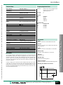
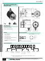
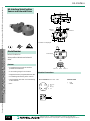
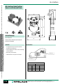
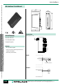
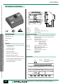
AS-Interface Logic Module
44
80
24
US
Model Number
Connections
VAA-2EA-G1-ZE/E2-LG
Logic module
Inputs
2 inputs/2outputs
Features
ext
• Inputs can be logically linked to outputs
using parameter bits
Outputs
Courtesy of Steven Engineering, Inc. Ÿ 230 Ryan Way, South San Francisco, CA, 94080-6370 Ÿ Main Office: (650) 588-9200 Ÿ Outside Local Area: (800) 258-9200 Ÿ www.stevenengineering.com
AS-Interface
• Can operate as a standard 2 input/2 output
I/O module
• LEDs for inputs and outputs
• Uses standard AS-Interface flat or round
cable mounting bases
• IP67
Inputs
Face view - female
3
4
2
1
1
2
3
4
Input power (+)
Input*
Input power (-)
Input*
Outputs
Face view - female
3
4
2
1
1
2
3
4
n.c.
n.c.
External power (-)
Switch output (+)
* Internally connected
208
Pepperl+Fuchs® Inc. • 1600 Enterprise Parkway • Twinsburg, Ohio 44087-2245
Telephone (330) 425-3555 • FAX (330) 405-4710 • E-mail: [email protected]
Courtesy of Steven Engineering, Inc. Ÿ 230 Ryan Way, South San Francisco, CA, 94080-6370 Ÿ Main Office: (650) 588-9200 Ÿ Outside Local Area: (800) 258-9200 Ÿ www.stevenengineering.com
AS-Interface
Programming Instructions
Technical Data:
Model Number
VAA-2EA-G1-ZE/E2-LG
Connections
AS-Interface/external power
Inputs/outputs
Operating voltage VB
Operating current Ie
yellow flat cable/black flat cable or standard
round cable
V1 (M12x1) quick disconnect
via AS-Interface, reverse polarity protection
£ 70 mA
Inputs
OFF IIn
ON IIn
Iin
VOUT
I OUT
two 2- or 3-wire sensors, DC, sourcing
£ 1 mA
³ 4.5 mA
£ 7 mA
20-30 VDC from AS-Interface
70 mA, short circuit protection
Outputs
Load capacity
2, electronic
24 VDC, 500 mA (per output), 1 A total,
galvanically isolated
24 VDC +15% PELV
External power Vext
Address
IO-Code
ID-Code
preset to 00, can be changed via the
master or with a hand-held
addressing device.
7
F
Data Bit
Bit
D0
D1
D2
D3
Function
input I1
input I2
output O3
output O4
Parameter Bits
Function
Adjustment of the logic functions through P0 to P3
(refer to Logic Function on this page)
Indicators
4, Switch status (I1-I2, O3-O4)
LED yellow
Power (AS-Interface)/sensor
overload
EMC
Operating temperature tb
Storage temperature tl
Protection (IEC)
LED green/LED red
per EN 50 081-2, EN 50 082-2
-25 to +60°C (-13 to +140°F)
-25 to +85°C (-13 to +185°F)
IP67
Function:
- Logically connects inputs I1 and I2 to outputs O3 and O4
- Uses all four inputs and outputs
Outputs:
U-G1FF
Base for connection of AS-Interface flat cable and the
24 VDC flat cables
U-G1FFA
Base for connection of AS-Interface flat cable and the
24 VDC flat cables with addressing jack.
Description
Inputs:
Accessories
U-G1PP
Base for connection of AS-Interface round cable and
external power supply
D0, D1 switch conditions on inputs I1, I2
(1 = Switch status ON)
D2, D3 switch conditions on outputs O3, O4
(1 = Switch status ON)
D0, D1 not used
D2, D3 Master-release of outputs O3, O4
(0 = output with no power)
Note:
The outputs are switched to a de-energized state (after approximately 10 ms) when an
interruption of the bus communications (master outage) occurs.
Logic Function:
PG11-1/2"NPT
1/2" NPT conduit adapter for U-G1P base
VAZ-V1-B
Protective cover
VBP-HH1-110V
Hand-held addressing device
VAZ-PK-V1-CINCH
Cable from module to hand-held addressing device
P3
P2
P1
P0
Output
O3
Output
O4
0
0
0
0
0
0
0
0
1
1
1
1
1
1
1
1
0
0
0
0
1
1
1
1
0
0
0
0
1
1
1
1
0
0
1
1
0
0
1
1
0
0
1
1
0
0
1
1
0
1
0
1
0
1
0
1
0
1
0
1
0
1
0
1
D2
I1
I1
I1
I1
I1 AND I2
I1 AND I2
I1 AND I2
I1 OR I2
I1 OR I2
I1 XOR I2
reserved
reserved
reserved
reserved
D2
D3
I2
I1 AND I2
I1 OR I2
I1 XOR I2
I1 AND I2
I1 OR I2
I1 XOR I2
I1 OR I2
I1 XOR I2
I1 XOR I2
(2EA-relationship)
(directly affect)
D3
(2EA-relationship)
Mounting hole dimensions for bases
Pepperl+Fuchs® Inc. • 1600 Enterprise Parkway • Twinsburg, Ohio 44087-2245
Telephone (330) 425-3555 • FAX (330) 405-4710 • E-mail: [email protected]
209
AS-Interface Pushbutton Module
30
45
80
Courtesy of Steven Engineering, Inc. Ÿ 230 Ryan Way, South San Francisco, CA, 94080-6370 Ÿ Main Office: (650) 588-9200 Ÿ Outside Local Area: (800) 258-9200 Ÿ www.stevenengineering.com
AS-Interface
US
Model Number
Button Color Options
VAA-LT2-G1
Lighted pushbutton module
2 inputs/2outputs
Features
• 2 integrated illuminated buttons
• White LEDs with colored lens covers
• Uses standard AS-Interface flat or round
cable mounting bases
• IP67
The default lens colors for the VAA-LT2-G1 is as follows:
button 1 = green
button 2 = red
The folowing optional lens colors are also available:
black (opaque)
gray (opaque)
red
green
yellow
white (clear)
orange
blue
To order optional lens colors, indicate positions and color on the order.
(i.e. VAA-LT2-G1 button 1 = blue, button 2 = orange)
210
Pepperl+Fuchs® Inc. • 1600 Enterprise Parkway • Twinsburg, Ohio 44087-2245
Telephone (330) 425-3555 • FAX (330) 405-4710 • E-mail: [email protected]
Courtesy of Steven Engineering, Inc. Ÿ 230 Ryan Way, South San Francisco, CA, 94080-6370 Ÿ Main Office: (650) 588-9200 Ÿ Outside Local Area: (800) 258-9200 Ÿ www.stevenengineering.com
AS-Interface
Programming Instructions
Technical Data:
Model Number
Connections
AS-Interface
Operating voltage VB
VAA-LT2-G1
Address
Operating current Ie
yellow flat cable or standard round cable
from AS-Interface, reverse polarity
protection
< 55 mA
Inputs
2 integrated pushbuttons
Outputs
2 integrated LEDs, powered from
AS-Interface
EMC
Operating temperature
Storage temperature
Protection (IEC)
per EN 50 081-2, EN 50 082-2
-25 to + 60°C (-13 to +140°F)
-40 to +85°C (-13 to +185°F)
IP67
IO-Code
ID-Code
preset to 00, can be changed via the
master or with a hand-held
addressing device.
3
F
Bit Assignment
Bit
Function
D0
button 2 (red)
D1
button 1 (green)
D2
LED 2 (red)
D3
LED 1 (green)
Accessories
U-G1F
Base for connection of AS-Interface flat cable
U-G1FA
Base for connection of AS-Interface flat cable with
addressing jack.
U-G1P
Base for connection of AS-Interface round cable
Description
The VAA-LT2-G1 lighted push button module provides a link between the
maintenance personnel and AS-Interface. LEDs integrated in the buttons
display the current status. The IP67 lighted buttons are ideal for use in the field.
Use the U-G1F base to connect to the AS-Interface flat cable, and use the
U-G1P base to connect to the round cable. The VAA-LT2-G1 is fully
powered from AS-Interface. The AS-Interface standardized base U-G1FA
includes an integrated addressing jack that allows easy connection to the
hand-held addressing device.
PG11-1/2"NPT
1/2" NPT conduit adapter for U-G1P base
VAZ-V1-B
Protective cover
VBP-HH1-110V
Hand-held addressing device
VAZ-PK-V1-CINCH
Cable from module to hand-held addressing device
Mounting hole dimensions for bases
Pepperl+Fuchs® Inc. • 1600 Enterprise Parkway • Twinsburg, Ohio 44087-2245
Telephone (330) 425-3555 • FAX (330) 405-4710 • E-mail: [email protected]
211
AS-Interface Pneumatic Module
90
US
Model Number
102
48
80
Courtesy of Steven Engineering, Inc. Ÿ 230 Ryan Way, South San Francisco, CA, 94080-6370 Ÿ Main Office: (650) 588-9200 Ÿ Outside Local Area: (800) 258-9200 Ÿ www.stevenengineering.com
AS-Interface
Examples for AS-Interface Airbox Functions
3/2-way valve
VAA-2EA-G1-ZE/P-S
Pneumatic module
2 inputs/2 outputs
Features
4/2-way valve
• Connection of 2- or 3-wire sensors
• Uses standard AS-Interface flat or round
cable mounting bases
• Connects directly to pneumatic cylinders
• Easy installation
• IP65
5/3-way valve
Outputs
5/3-way valve
without pressure
O-3
212
with pressure
switched
O-4
Pepperl+Fuchs® Inc. • 1600 Enterprise Parkway • Twinsburg, Ohio 44087-2245
Telephone (330) 425-3555 • FAX (330) 405-4710 • E-mail: [email protected]
Courtesy of Steven Engineering, Inc. Ÿ 230 Ryan Way, South San Francisco, CA, 94080-6370 Ÿ Main Office: (650) 588-9200 Ÿ Outside Local Area: (800) 258-9200 Ÿ www.stevenengineering.com
AS-Interface
Programming Instructions
Technical Data:
Model Number
Connections
AS-Interface
VAA-2EA-G1ZE/P-S
Operating current Ie
yellow flat cable/black flat cable or
standard round cable
V1 (M12x1) quick disconnect
air hose connector (8 mm)
from AS-Interface, reverse polarity
protection
< 45 mA
Inputs
two 2- or 3-wire sensors, DC, sourcing
Inputs
Outputs
Operating voltage VB
OFF Iin
ON Iin
Iin
Vout
Iout
< 1 mA
> 4.5 mA
£ 7 mA
20-30 VDC from AS-Interface
100 mA, short circuit protection
Outputs
Pneumatic outputs
Pressure (min)
Pressure (max)
Air throughput rate
Exhaust
Seated valve nominal width
Compressed air consistancy
2, integrated solenoids
3/2-way valves
2 bar
8 bar
400 NI/min
Sinterfilter
5 mm
filtered (5 µm),
oiled or unoiled compressed air
Indicators
4, Switch status (I1-I2, O3-O4)
Power (AS-Interface)
EMC
Operating temperature
Storage temperature
Protection (IEC)
LED yellow
LED green
per EN 50 081-2, EN 50 082-2
0 to + 55°C (32 to +131°F)
-20 to +55°C (-4 to +131°F)
IP65
Address
IO-Code
ID-Code
preset to 00, can be changed via the
master or with a hand-held
addressing device.
3
F
Data Bit
Bit
D0
D1
D2
D3
Function
input I1
input I2
output O3
output O4
Parameter Bits
Bit
Function (1/0)
P0
not used
P1
not used
P2
not used
P3
not used
Accessories
U-G1F
Base for connection of AS-Interface flat cable
U-G1FA
Base for connection of AS-Interface flat cable with
addressing jack.
U-G1P
Base for connection of AS-Interface round cable
PG11-1/2"NPT
1/2" NPT conduit adapter for U-G1P base
Description
The VAA-2EA-G1-ZE/P-S module has two inputs for 2- or 3-wire sensors and
two pneumatic outputs with a high air throughput rate for direct control of
pneumatic actuators in the field. Two isolated 3/2 way valves are built in the
module. Sensors are connected to the module with a V1 (M12x1) quick
disconnect and jacketed 8 mm quick disconnects attach the outputs to the
pneumatic cylinders.
Use the U-G1F base to connect to the AS-Interface flat cable, and use the
U-G1P base to connect to the round cable. The VAA-2EA-G1-ZE/P-S is fully
powered from AS-Interface. The AS-Interface standardized base U-G1FA
includes an integrated addressing jack that allows easy connection to the
hand-held addressing device.
VAZ-V1-B
Protective cover
VBP-HH1-110V
Hand-held addressing device
VAZ-PK-V1-CINCH
Cable from module to hand-held addressing device
Mounting hole dimensions for bases
Pepperl+Fuchs® Inc. • 1600 Enterprise Parkway • Twinsburg, Ohio 44087-2245
Telephone (330) 425-3555 • FAX (330) 405-4710 • E-mail: [email protected]
213
AS-Interface Serial Absolute
Rotary Encoder
Clamping flange
21
93.5
20
10
3
3 x M3
57.5
3
7 deep
Æ 10 h6
Æ 58
Æ 52
Æ 36 f8
12
0°
M12 x 1
Æ 48 ± 0,1
Synchro flange
4
10 3
83.5
69.5
3 x M4
3
10 deep
Æ 58
Æ 50 h7
Æ 6 h6
0°
12
US
Model Number
53
Courtesy of Steven Engineering, Inc. Ÿ 230 Ryan Way, South San Francisco, CA, 94080-6370 Ÿ Main Office: (650) 588-9200 Ÿ Outside Local Area: (800) 258-9200 Ÿ www.stevenengineering.com
AS-Interface
Series BVE 10, BVM 10
See Key to Model Numbers
M12 x 1
Features
Æ 42 ± 0.1
17.5
Electrical Connections
• 13-bit single-turn
AS-i Connection Face view - male
• 16-bit multi-turn
• Gray or binary code
4
3
• Transmission of the position data over
4 AS-Interface slaves
1
2
• Programming and addressing via ASInterface
1
2
3
4
AS-i (+)
n.c.
AS-i (-)
n.c.
NOTE:
Pin 2 and pin 4 must not be connected.
Key to Model Numbers
B V
1
0 -
B -
Data format
Design
Connections
E = Single-turn
Flange
^ Clamping flange
1=
Shaft
B = AS-Interface
0 = Æ 10 x 20 mm
F = V1, radial
M = Multi-turn
2^
= Synchro flange
2 = Æ 12 x 20 mm
G = V1, axial
-
Steps per
revolution*
Number of
rotations*
6 = Æ 6 x 10 mm
* Note: BVM 10 - Steps per revolution £ 8,192. Steps per revolution x number of rotations £ 65,536.
BVE 10 - Steps per revolution = 8,192.
214
Pepperl+Fuchs® Inc. • 1600 Enterprise Parkway • Twinsburg, Ohio 44087-2245
Telephone (330) 425-3555 • FAX (330) 405-4710 • E-mail: [email protected]
Courtesy of Steven Engineering, Inc. Ÿ 230 Ryan Way, South San Francisco, CA, 94080-6370 Ÿ Main Office: (650) 588-9200 Ÿ Outside Local Area: (800) 258-9200 Ÿ www.stevenengineering.com
AS-Interface
Programming Instructions
Technical Data:
Model Number
Connections
AS-Interface
Operating voltage
Operating current
Mechanical
Housing
Flange
Code-disc
Shaft
Shaft seal
Max. speed
Inertia
Starting torque
Torque
Max. shaft load, axial
Max. shaft load, radial
Min. mechanical life
Environmental Conditions
Operating temperature
Storage temperature
Protection (IEC)
See Model Number
V1 (M12x1) quick disconnect,
axial or radial
from AS-Interface
< 100 mA
Slave
Slave
Slave
Slave
Pre-set
Address
1
2
3
4
A
B
C
D
IO-Code
ID-Code
7
0
0
0
F
F
F
F
Parameter Bits (slave A)
aluminium, black finish
aluminium
metal
stainless steel
oil/saltwater-resistant
6000 rpm
30 gcm2
< 1.5 Ncm (at 20 °C)
< 1.0 Ncm (at 20 °C)
40 N
60 N
4 x 10¹⁰ Rot.
PB
P0
P1
P2
P3
0
gray code
with response bit
counter clockwise
operating mode
not used
Data Input without Response Bit
Slave A
D0
D1 D2
Bit0 Bit1 Bit2
Slave B
D0 D1
Bit4 Bit5
D3
Bit3
Slave C
-20 to +80°C (-13 to +176°F)
-25 to +85°C (-13 to +185°F)
IP65
Description
The absolute rotary encoders use 4 AS-Interface addresses for transmitting up
to 16 bit position data. These encoders offer a number of operating modes that
will guarantee trouble-free operation.
1
binary code
without response bit
clockwise
operating mode
not used
D0
Bit8
D1
Bit9
D2
Bit6
D3
Bit7
Slave D
D2 D3
D0
D1
D2
D3
Bit10 Bit11 Bit12 Bit13 Bit14 Bit15
Data Input with Response Bit
Slave A
D0
D1 D2
Bit0 Bit1 Bit2
D3
QA
Slave B
D0 D1
Bit3 Bit4
Slave C
D0
D1 D2
Bit6 Bit7 Bit8
D3
QC
Slave D
D0 D1
D2
D3
Bit9 Bit10 Bit11 QD
D2
Bit5
D3
QB
Data Output (slave A)
1. Sequential Addresses and Gray-Codes
Since these 4 addresses are sequentially polled, the data can originate from 4
different measurement times. In order to minimize this effect, addresses A, B,
C and D should be sequential addresses and, if possible, Gray Code should
be used.
2. Temporary Storage of the Position Data in the Rotary Encoder
A controller exchanges input and output data at intervals that are independent
of the AS-Interface scans. Therefore, the encoder data can originate from 2
different AS-Interface cycles. This problem can be avoided through temporary
storage of the position data in the rotary encoder. The controller transfers the
data bits D2 and D3 for address A to enable the temporary storage feature. The
controller then receives the encoder data simultaneously from the AS-Interface
master which was stored from the previous cycle. The data is delayed one scan
as a precautionary measure.
3. Temporary Storage and Transfer with Response Bits
If any data from the rotory encoder is interrupted during transmission, it is
possible that not all of the data transferred to the controler originates from the
same position in the data word. The controller can check the data integrity for
a single data word by comparing the 4 response bits. This is accomplished
through the transfer of one response bit per address. As a result of using the
response bits, the size of the usable data is reduced from 16 to 12 bits.
D0/D1: 00 or 11
01
10
D2/D3: 00 or 11
10 or 01
standard operation
the rotary encoder is set to 0
the rotary encoder is set to 90°
output data is not stored
output data is stored
Accessories
9203
Mounting bracket for clamping flange
9310
Synchro mounting flange
9401, 9402, 9403
Encoder shaft couplers
For more information on mounting accessories and
adapters, refer to the Rotary Encoders Catalog.
Pepperl+Fuchs® Inc. • 1600 Enterprise Parkway • Twinsburg, Ohio 44087-2245
Telephone (330) 425-3555 • FAX (330) 405-4710 • E-mail: [email protected]
215
Courtesy of Steven Engineering, Inc. Ÿ 230 Ryan Way, South San Francisco, CA, 94080-6370 Ÿ Main Office: (650) 588-9200 Ÿ Outside Local Area: (800) 258-9200 Ÿ www.stevenengineering.com
AS-Interface
AS-Interface Valve Position
Sensor and Solenoid Driver
Solenoid
driver
AS-Interface
Actuator not displayed.
US
Model Number
Solenoid LED
NCN3-F31-B3-V1-K
Valve position indicator and solenoid
driver
LEDs
Features
• 2 integrated sensors and AS-Interface
powered solenoid driver
• 3 mm sensing range for each sensor
Sensor 2
Power
Sensor 1
Electrical Connections
• Integrated sensors programmable N.O./N.C.
• Coil breakage monitoring of the sensors
• Lead breakage and short circuit monitoring
of the solenoid
AS-i Connection Face view - male
• IP67
216
4
3
1
2
1
2
3
4
AS-i (+)
n.c.
AS-i (-)
n.c.
Solenoid Cable
+
-
Red
Yellow
Pepperl+Fuchs® Inc. • 1600 Enterprise Parkway • Twinsburg, Ohio 44087-2245
Telephone (330) 425-3555 • FAX (330) 405-4710 • E-mail: [email protected]
Courtesy of Steven Engineering, Inc. Ÿ 230 Ryan Way, South San Francisco, CA, 94080-6370 Ÿ Main Office: (650) 588-9200 Ÿ Outside Local Area: (800) 258-9200 Ÿ www.stevenengineering.com
AS-Interface
Programming Instructions
Technical Data:
Model Number
Connections
AS-Interface
Output
Operating voltage VB
Operating current Ie
Inputs
Shielded
Sensing range sa
Switching frequency f
Outputs
Output voltage V out
Output current I out
Indicators
2, switch status
Power (AS-Interface)
Solenoid on/LB or SC
EMC
Operating temperature tb
Storage temperature tl
Protection (IEC)
NCN3-F31-B3-V1-K
V1 (M12x1) quick disconnect
1 M pigtail
from AS-Interface, reverse polarity
protection
£ 150 mA
2, integrated sensors, powered from
AS-Interface
yes
2.4-3.7 mm
³ 100 Hz
1, solenoid driver*
from AS-Interface, reverse polarity
protection
100 mA, short circuit protection
Address
IO-Code
ID-Code
preset to 00, can be changed via the
master or with a hand-held
addressing device.
D
F
Data Bits
Bit
Function
D0
solenoid status
"0" solenoid off
"1" solenoid on
D1
solenoid error 1
"0" lead breakage/short circuit
"1" no error
D2
switch output sensor I 2
"0" target present (on)
"1" target absent (off)
D3
switch output sensor II
"0" target present (on)
"1" target absent (off)
2
Parameter Bits
Bit
Function (1/0)
LED yellow
LED green
LED yellow/LED red
per EN 60 947-5-2
-25 to +70°C (-13 to +158°F)
-40 to +85°C (-40 to +185°F)
IP67
* Valve power consumption maximum 2.6 W/24 VDC
P0
watchdog 3
"0" inactive
"1" active
P1
not used
P2
mode of operation sensor I
"1" normally open
"0" normally closed
P3
mode of operation sensor II
"1" normally open
"0" normally closed
4
4
1 Monitoring only occurs with actuated solenoid
(D0 = "1")
2 Applies to N.C. function (P2/P3 = "1" ; preset), for
N.O. function (P2/P3 = "0") reverse relationship
3 Watchdog active: output returns to its de-energized state if a communications fault occurs
4 Default setting: normally closed
Description
Accessories
The NCN3-F31-B3-V1-K is a dual inductive sensor and solenoid driver used
to indicate and control the valve position of actuators. This dual sensor uses two
screws to mount directly on the actuator and requires no additional adjustment.
VBP-HH1-110V
Hand-held addressing device
The NCN3-F31-B3-V1-K connects to AS-Interface with a V1(M12x1) quick
disconnect. The D1 data bit monitors the solenoid for lead breakage and short
circuits. Yellow LEDs display the current switch conditions. A dual LED displays
the current solenoid status or if an error exists.
BT 65
Positioning puck
BT 115
Positioning puck
The sensors can be programmed as normally open or normally closed contacts
(parameter bits P2 and P3). If the watchdog is active and a communication fault
occurs on the network, the ouput returns to its de-energized state. The P0
parameter bit disables the watchdog function.
Pepperl+Fuchs® Inc. • 1600 Enterprise Parkway • Twinsburg, Ohio 44087-2245
Telephone (330) 425-3555 • FAX (330) 405-4710 • E-mail: [email protected]
217
AS-Interface Valve Position
Sensor and Solenoid Driver
34
23
15.5
8
Sensor
1
92
Sensor
2
7
58
81
Courtesy of Steven Engineering, Inc. Ÿ 230 Ryan Way, South San Francisco, CA, 94080-6370 Ÿ Main Office: (650) 588-9200 Ÿ Outside Local Area: (800) 258-9200 Ÿ www.stevenengineering.com
AS-Interface
US
Model Number
PL1-F25-B3-S
67
29
Valve position indicator and solenoid
driver circuit board
Features
Connections
• 2 integrated sensors and AS-Interface
powered solenoid driver
• Lead breakage and short circuit monitoring
of the solenoid
• Watchdog functionality
1 2
• LED indication for inputs and output
Solenoid 1 - 2
1 2 3 4
AS-Interface 1 - 4
Connections
AS-Interface
Pin 1
218
Solenoid
AS-i +
Pin 1
Solenoid +
Pin 2
AS-i -
Pin 2
Solenoid -
Pin 3
AS-i +
Pin 4
AS-i -
Pepperl+Fuchs® Inc. • 1600 Enterprise Parkway • Twinsburg, Ohio 44087-2245
Telephone (330) 425-3555 • FAX (330) 405-4710 • E-mail: [email protected]
Courtesy of Steven Engineering, Inc. Ÿ 230 Ryan Way, South San Francisco, CA, 94080-6370 Ÿ Main Office: (650) 588-9200 Ÿ Outside Local Area: (800) 258-9200 Ÿ www.stevenengineering.com
AS-Interface
Technical Data:
Model Number
Connections
AS-Interface
Output
Operating voltage VB
Operating current Ie
Inputs
Switching frequency f
Outputs
Output voltage Vout
Output current Iout
Programming Instructions
PL1-F25-B3-S
Address
removable terminals
removable terminals
from AS-Interface, reverse polarity
protection
£ 150 mA
2, integrated sensors, powered from
AS-Interface
³ 100 Hz
1, solenoid driver*
from AS-Interface, reverse polarity
protection
100 mA, short circuit protection
IO-Code
ID-Code
preset to 00, can be changed via the
master or with a hand-held
addressing device.
D
F
Data Bits
Bit
Function
D0
solenoid status
"1" solenoid on
"0" solenoid off
D1
not used
D2
switch output sensor I
"1" target present (on)
"0" target absent (off)
D3
switch output sensor II
"1" target present (on)
"0" target absent (off)
* Valve power consumption maximum 2.6 W/24 VDC
Parameter Bits
Bit
Function (1/0)
P0
watchdog
= 1, outputs return to their deenergized state when a
communications fault exists
= 0, outputs latch in their last state
when a communications fault
exists
P1
not used
P2
not used
P3
not used
Description
Accessories
Quarter-turn valves are commonly used to control product flow throughout the
processing industry. These valves are typically controlled pneumatically and
open or closed indication is reported back to the controller. Standard housings
per VDI/VDE 3845 contain the open or closed proximity sensors used by a
control valve.
VBP-HH1-110V
Hand-held addressing device
The PL1-F25-B3-S circuit board was developed for use in standard housings
and includes connection terminals, the AS-Interface circuit board and dual
sensor.
BT 65
Positioning puck
Indicators
2, switch status
2, switch status
Power (AS-Interface)
Solenoid on
EMC
Operating temperature tb
Storage temperature tl
LED yellow on board
LED yellow in sensor
LED green
LED yellow
per EN 60 947-5-2
-25 to +60°C (-13 to +140°F)
-40 to +85°C (-40 to +185°F)
VAZ-PK-V1-CINCH
Connection cable, module/addressing device
A jack is provided for programming the AS-Interface address using the cinch
cable and a hand-held addressing device. When the output is active, the
solenoid is monitored for lead breakage.
Pepperl+Fuchs® Inc. • 1600 Enterprise Parkway • Twinsburg, Ohio 44087-2245
Telephone (330) 425-3555 • FAX (330) 405-4710 • E-mail: [email protected]
219
AS-Interface Circuit Board
45.5
19.5
75.5
40.5
11
40
US
Connections
Model Number
Rail dimension: 2.54
VAA-4EA-CB-E/E2
Circuit board module
Inputs
4 inputs/4 outputs
Features
• Bus powered outputs
Outputs
Courtesy of Steven Engineering, Inc. Ÿ 230 Ryan Way, South San Francisco, CA, 94080-6370 Ÿ Main Office: (650) 588-9200 Ÿ Outside Local Area: (800) 258-9200 Ÿ www.stevenengineering.com
AS-Interface
• Short circuit and overload protection for
inputs and outputs
• Watchdog functionality
Inputs
4, 17 (+)
Input (I1-I4)
5, 8 (-)
+
Load
-
for 3-wire sensors
Outputs
Output (O1-O4)
11, 14 (-)
+
LED
220
Pepperl+Fuchs® Inc. • 1600 Enterprise Parkway • Twinsburg, Ohio 44087-2245
Telephone (330) 425-3555 • FAX (330) 405-4710 • E-mail: [email protected]
Courtesy of Steven Engineering, Inc. Ÿ 230 Ryan Way, South San Francisco, CA, 94080-6370 Ÿ Main Office: (650) 588-9200 Ÿ Outside Local Area: (800) 258-9200 Ÿ www.stevenengineering.com
AS-Interface
Technical Data:
Model Number
Connections
AS-Interface
Inputs/outputs
Operating voltage VB
Programming Instructions
VAA-4EA-CB-E/E2
Operating current Ie
Solder pins
Solder pins
from AS-Interface, reverse polarity
protection
£ 200 mA
Inputs
OFF IIn
ON IIn
Iin
VOUT
four 2- or 3-wire sensors, DC, sourcing
£ 1.5 mA
³ 5 mA
£ 7 mA
20-30 VDC from AS-Interface
Outputs
Load capacity
4, electronic
45 mA per output
24 VDC, 180 mA total
Indicators
8, Switch status (I1-I4, O1-O4)
Power (AS-Interface)
EMC
Operating temperature tb
Storage temperature tl
Protection (IEC)
Address
IO-Code
ID-Code
preset to 00, can be changed via the
master or with a hand-held
addressing device.
7
0
Data Bits
Bit
D0
D1
D2
D3
Function
input I1/output
input I2/output
input I3/output
input I4/output
O1
O2
O3
O4
Parameter Bits
Bit
Function (1/0)
P0
not used
P1
not used
P2
not used
P3
not used
LED yellow
LED green
per EN 50 081-2, EN 50 082-2
-25 to +70°C (-13 to +158°F)
-40 to +70°C (-40 to +158°F)
IP00
Description
The VAA-4EA-CB-E/E2 is an AS-Interface circuit board solution for an ASInterface I/O module. AS-Interface supplies power to the module and the input
and outputs are short circuit and overload protected. If the watchdog is active
and a communication fault occurs on the network, the ouput returns to its deenergized state.
P+F can customize circuit board models to meet your specific applications.
Pepperl+Fuchs® Inc. • 1600 Enterprise Parkway • Twinsburg, Ohio 44087-2245
Telephone (330) 425-3555 • FAX (330) 405-4710 • E-mail: [email protected]
221
AS-Interface Data Coupler
115
US
Connections
AS-i + (System 1)
Model Number
AS-i - (System 1)
VAA-4EA-KF-DK
Data coupler
Addressing jack
AS-i System 1
O11
O10
O12
O22
O20
Features
• Module for bidirectional data exchange
between two AS-Interface systems
-
Addressing jack
AS-i System 2
• Two AS-Interface connections per system
• Two 4 input/4 output modules (1 per
system, internally connected)
PWR
O13
O23
PWR
2
O21
• AS-Interface connections via power rail and
terminals
AS-i - (System 2)
• Removable, mechanically-keyed terminals
AS-i + (System 2)
• LED indication for all outputs
• Two integrated addressing jacks
(+) 1
O10
I20
O11
I21
O12
I22
O13
I23
9 (+)
AS-i 2
AS-i 1
(-) 2
5 (-)
8 (-)
PWR2
4
Power Rail
5
PWR1
222
6 (+)
I10
O20
I11
O21
I12
O22
I13
O23
Pepperl+Fuchs® Inc. • 1600 Enterprise Parkway • Twinsburg, Ohio 44087-2245
Telephone (330) 425-3555 • FAX (330) 405-4710 • E-mail: [email protected]
107
20
93
Courtesy of Steven Engineering, Inc. Ÿ 230 Ryan Way, South San Francisco, CA, 94080-6370 Ÿ Main Office: (650) 588-9200 Ÿ Outside Local Area: (800) 258-9200 Ÿ www.stevenengineering.com
AS-Interface
Courtesy of Steven Engineering, Inc. Ÿ 230 Ryan Way, South San Francisco, CA, 94080-6370 Ÿ Main Office: (650) 588-9200 Ÿ Outside Local Area: (800) 258-9200 Ÿ www.stevenengineering.com
AS-Interface
Programming Instructions
Technical Data:
Model Number
Connections
AS-Interface
Inputs/outputs
Operating voltage VB
Operating current Ie
Indicators
8, Switch status (O1-O4, O1-O4)
2, Power (AS-Interface)
EMC
Operating temperature
Storage temperature
Protection (IEC)
VAA-4EA-KF-DK
Address
terminals or Power Rail (System 1)
terminals (System 2)
internally connected
from AS-Interface, reverse polarity
protection
< 50 mA (System 1)
< 50 mA (System 2)
IO-Code
ID-Code
LED yellow
LED green
per EN 50 081-2, EN 50 082-2
-25 to + 70°C (-13 to +158°F)
-25 to +85°C (-13 to +185°F)
IP20
preset to 00, can be changed via
the master or with a hand-held
addressing device.
7
F
Data Bits (System 1)
Bit
Function
D0
input I10/output O10
D1
input I11/output O11
D2
input I12/output O12
D3
input I13/output O13
Data Bits (System 2)
Bit
Function
D0
input I20/output O20
D1
input I21/output O21
D2
input I22/output O22
D3
input I23/output O23
Parameter Bits
Bit
Function (1/0)
P0
not used
P1
not used
P2
not used
P3
not used
Description
Accessories
The data coupler VAA-4EA-KF-DK is used for bidirectional data exchange
between two independent AS-Interface systems. Therefore the data exchange
can be carried out locally, without having to transfer the data back to the control
system. This is of particular advantage in time-critical applications.
VBP-HH1-110V
Hand-held addressing device
The inputs and outputs are electrically isolated from each other so that the two
independent AS-Interface systems can be connected. The electrical isolation
eliminates a potential problem of a floating ground. The status of all the outputs
is indicated via 8 LEDs provided on the front of the module. Two additional LEDs
signal the presence of the AS-Interface voltage on the two circuits.
The connection to the AS-Interface System 1 can be accomplished through
terminal connections or using the Power Rail and System 2 by terminals only.
Two addressing jacks are available for connection of the hand-held addressing
device to each module. The KF modules allow the exchange of components while
under power and the mechanically-keyed, removable terminals enable simple
replacement of the module and aid installation.
VAZ-PK-V1-CINCH
Cable from module to addressing device
UPR-05
Continuous Power Rail with aluminum DIN rail and
cover, 2 m long
UPR E
UPR 05 end cap
PR 05
Power Rail, 0.5 m long
Pepperl+Fuchs® Inc. • 1600 Enterprise Parkway • Twinsburg, Ohio 44087-2245
Telephone (330) 425-3555 • FAX (330) 405-4710 • E-mail: [email protected]
223
AS-Interface Control Relay
1
2
PEPPERL+FUCHS
DEL
ALT
6
ESC
45
3
90
Courtesy of Steven Engineering, Inc. Ÿ 230 Ryan Way, South San Francisco, CA, 94080-6370 Ÿ Main Office: (650) 588-9200 Ÿ Outside Local Area: (800) 258-9200 Ÿ www.stevenengineering.com
AS-Interface
4
OK
5
7
71.5
4.5
47.5
58
1 DEL key
US
5 ESC key
2 ALT key
6 LCD display
3 Cursor key
7 Socket for PC Interface (with cover)
4 OK key
Model Number
Controls and displays
EASY412-DC-TC
1 DEL key:
2 ALT key:
Control relay
3 Cursor keys:
IP20
Features
• 8 digital inputs, two of which can be used
as analog inputs
4 OK key:
5 ESC key:
• 4 transistor outputs
• 4-line LCD display
LCD display:
• Control panel/keys
• Real-time clock/timing relay
Deletion of contacts, relays, connections, ladder rungs
Indicate connections, N.O. or N.C. contact selection,
insert ladder rung
right, left, up, down
Contacts, relays, number selection
P key for: Input P1 cursor left
Input P2 cursor up
Input P3 cursor right
Input P4 cursor down
Step forward in menu, accept entry
Take one step back in menu
Menu, exit parameter function relay
Exit without saving
Inputs/outputs status indication
Operating status
Ladder diagram
Display time
• Retentive memory functions
• Interface for transfer to memory card or PC
• No software required
Connections
VB
24 VDC
+24V
I1-I8
I7 and I8
0V 0V
DC24V
I1
I2
I3
inputs 24 VDC
can also be used as 0-10 V
analog inputs
I4
I5
I6
I7
I8
Input 8 x DC, (I7,I8 0-10V)
Output
4xTransistor/0.5A
+24V Q
224
0VQ
Q1 Q2
Q3 Q4
Pepperl+Fuchs® Inc. • 1600 Enterprise Parkway • Twinsburg, Ohio 44087-2245
Telephone (330) 425-3555 • FAX (330) 405-4710 • E-mail: [email protected]
Courtesy of Steven Engineering, Inc. Ÿ 230 Ryan Way, South San Francisco, CA, 94080-6370 Ÿ Main Office: (650) 588-9200 Ÿ Outside Local Area: (800) 258-9200 Ÿ www.stevenengineering.com
AS-Interface
Technical Data:
References
Model Number
EASY412-DC-TC
Connections
Power
Inputs/outputs
Operating voltage VB
Operating current Ie
terminals
terminals
24 VDC, +20/-15 %
£ 80 mA
Digital inputs (I1-I8)
OFF VIn
ON VIn
ON I In
8*, mechanical contacts or 3-wire
sensors, DC, sourcing
£ 5 VDC
³ 15 VDC
£ 3.3 mA
Analog inputs (I7-I8)
Voltage range
Resolution
Input impedance
2*, 0-10 VDC
0-10 VDC
0.1 VDC
11.2 kW
Outputs
Load capacity
4, electronic
24 VDC, 500 mA (per output),
galvanically isolated
Indicators
LCD display
Operating temperature tb
Storage temperature tl
Protection (IEC)
Manual: EASY 412, EASY 600 User's Manual
The documentation and software are included with
the unit.
Training Guide: EASY 412, EASY 600
• Contact Pepperl+Fuchs
4 line
-25 to +55°C (-13 to +131°F)
-40 to +70°C (-40 to +158°F)
IP20
* 8 digital inputs, two of which can be used as analog inputs.
Description
Accessories
The EASY412-DC-TC programmable relay is a simple, low-cost alternative to
hard-wired and conventional PLC solutions. It is ideal for controlling HVAC
systems, counting, security lighting, alarms or other applications typically
considered too simple to justify the expense of a PLC. This relay mounts on a 35
mm DIN rail or it can be screwed to a panel. The EEPROM stores the ladder
diagram program, eliminating the need for a battery backup. A separate memory
module is available for program backup or distribution to multiple units.
EASY-SOFT
Windows-based programming software for ladder
logic programming and printing.
Programming
The EASY412-DC-TC uses just four buttons and a cursor control to construct
ladder diagrams so you don’t have to learn a special logic language. Internal
relays enable interlocking functions and intermediate data storage. An optional
Windows-based software package is available for users who require advanced
programming capabilities.
EASY-M-8K
8K Flash memory module for back-up and copying
of programs from/to the EASY412-DC-TC.
EASY-M-16K
16K Flash memory module for back-up and copying
of programs from/to the EASY412-DC-TC.
EASY-PC-CAB
Programming cable for connectiong the EASY412DC-TC to a PC serial port, 2 m long.
Pepperl+Fuchs® Inc. • 1600 Enterprise Parkway • Twinsburg, Ohio 44087-2245
Telephone (330) 425-3555 • FAX (330) 405-4710 • E-mail: [email protected]
225
AS-Interface Control Relay
DEL
ALT
3
6
ESC
OK
45
PEPPERL+FUCHS
1
2
8
90
Courtesy of Steven Engineering, Inc. Ÿ 230 Ryan Way, South San Francisco, CA, 94080-6370 Ÿ Main Office: (650) 588-9200 Ÿ Outside Local Area: (800) 258-9200 Ÿ www.stevenengineering.com
AS-Interface
4
5
7
4.5
47.5
58
107.5
1 DEL key
US
5 ESC key
2 ALT key
6 LCD display
3 Cursor key
7 Socket for PC Interface (with cover)
4 OK key
8 LED Power/Run
Model Number
Controls and displays
EASY621-DC-TC
1 DEL key:
2 ALT key:
Control relay
3 Cursor keys:
IP20
Features
• 12 digital inputs, two of which can be used
as analog inputs
4 OK key:
5 ESC key:
• 4 transistor outputs
• 4-line LCD display
LCD display:
• Control panel/keys
• Real-time clock/timing relay
Deletion of contacts, relays, connections, ladder rungs
Indicate connections, N.O. or N.C. contact selection,
insert ladder rung
right, left, up, down
Contacts, relays, number selection
P key for: Input P1 cursor left
Input P2 cursor up
Input P3 cursor right
Input P4 cursor down
Step forward in menu, accept entry
Take one step back in menu
Menu, exit parameter function relay
Exit without saving
Inputs/outputs status indication
Operating status
Ladder diagram
Display time
• Retentive memory functions
• Interface for transfer to memory card or PC
Connections
• Can be expanded with EASY205-ASI as a 4
input/4 output AS-Interface module
I1-I12
I7 and I8
VB
24 VDC
inputs 24 VDC
can also be used as 0-10 V
analog inputs
• No software required
+24V
DC24V
0V 0V
I1
I2
I3
Input 12 x DC, (I7,I8
I4
I5
I6
I7
I8
I9
I10 I11 I12
0-10V)
Output
8xTransistor/0.5A
+24V Q
226
0VQ
Q1 Q2
Q3 Q4
Q5 Q6
Q7 Q8
Pepperl+Fuchs® Inc. • 1600 Enterprise Parkway • Twinsburg, Ohio 44087-2245
Telephone (330) 425-3555 • FAX (330) 405-4710 • E-mail: [email protected]
Courtesy of Steven Engineering, Inc. Ÿ 230 Ryan Way, South San Francisco, CA, 94080-6370 Ÿ Main Office: (650) 588-9200 Ÿ Outside Local Area: (800) 258-9200 Ÿ www.stevenengineering.com
AS-Interface
Technical Data:
References
Model Number
EASY621-DC-TC
Connections
Power
Inputs/outputs
EASY expansion
Operating voltage VB
Operating current Ie
terminals
terminals
integrated 6-pin connector
24 VDC, +20/-15%
£ 140 mA
Digital inputs (I1-I12)
OFF VIn
ON VIn
ON I In
12*, mechanical contacts or 3-wire
sensors, DC, sourcing
£ 5 VDC
³ 15 VDC
£ 3.3 mA
Analog inputs (I11-I12)
Voltage range
Resolution
Input impedance
2*, 0-10 VDC
0-10 VDC
0.1 VDC
11.2 kW
Outputs
Load capacity
8, electronic
24 VDC, 500 mA (per output),
galvanically isolated
Indicators
Program mode/run mode
LCD display
Operating temperature tb
Storage temperature tl
Protection (IEC)
Manual: EASY 412, EASY 600 User's Manual
The documentation and software are included with
the unit.
Training Guide: EASY 412, EASY 600
• Contact Pepperl+Fuchs
LED green/LED green flashing
4 line
-25 to +55°C (-13 to +131°F)
-40 to +70°C (-40 to +158°F)
IP20
* 12 digital inputs, two of which can be used as analog inputs.
Description
Accessories
The EASY621-DC-TC programmable relay is a simple, low-cost alternative to
hard-wired and conventional PLC solutions. It is ideal for controlling HVAC
systems, counting, security lighting, alarms or other applications typically
considered too simple to justify the expense of a PLC. This relay mounts on a 35
mm DIN rail or it can be screwed to a panel. The EEPROM stores the ladder
diagram program, eliminating the need for a battery backup. A separate memory
module is available for program backup or distribution to multiple units.
EASY-SOFT
Windows-based programming software for ladder
logic programming and printing.
Programming
The EASY621-DC-TC uses just four buttons and a cursor control to construct
ladder diagrams so you don’t have to learn a special logic language. Internal
relays enable interlocking functions and intermediate data storage. An optional
Windows-based software package is available for users who require advanced
programming capabilities.
EASY-M-16K
16K Flash memory module for back-up and copying
of programs from/to the EASY621-DC-TC.
Expandability
The EASY621-DC-TC can be expanded with a connection to AS-Interface using
the EASY205-ASI module. The exchange of data between the AS-Interface
master and the EASY 621 is provided by four inputs and four outputs as well as
four parameter bits of the EASY205-ASI module.
EASY-M-8K
8K Flash memory module for back-up and copying
of programs from/to the EASY621-DC-TC.
EASY-PC-CAB
Programming cable for connectiong the EASY621DC-TC to a PC serial port, 2 m long.
EASY205-ASI
AS-Interface expansion module for the EASY 612
control relay.
Pepperl+Fuchs® Inc. • 1600 Enterprise Parkway • Twinsburg, Ohio 44087-2245
Telephone (330) 425-3555 • FAX (330) 405-4710 • E-mail: [email protected]
227
AS-Interface EASY Expansion Module
45
PEPPERL+FUCHS
90
Courtesy of Steven Engineering, Inc. Ÿ 230 Ryan Way, South San Francisco, CA, 94080-6370 Ÿ Main Office: (650) 588-9200 Ÿ Outside Local Area: (800) 258-9200 Ÿ www.stevenengineering.com
AS-Interface
4.5
35
47.5
58
US
Model Number
Connections
EASY205-ASI
AS-Interface expansion module for the
EASY 621
IP20
Features
• AS-Interface expansion module for control
relay EASY621-DC-TC
AS-i
+
-
+
-
• Interface module and control relay together
form an intelligent standard AS-i module
• Internal watchdog for monitoring the
communication with the AS-i interface and
the control relay
• 4 inputs/4 outputs/4 parameters
• Functional display for device supply and
watchdog
228
Pepperl+Fuchs® Inc. • 1600 Enterprise Parkway • Twinsburg, Ohio 44087-2245
Telephone (330) 425-3555 • FAX (330) 405-4710 • E-mail: [email protected]
Courtesy of Steven Engineering, Inc. Ÿ 230 Ryan Way, South San Francisco, CA, 94080-6370 Ÿ Main Office: (650) 588-9200 Ÿ Outside Local Area: (800) 258-9200 Ÿ www.stevenengineering.com
AS-Interface
Technical Data:
Model Number
Programming Instructions
EASY205-ASI
Address
IO-Code
ID-Code
Operating current Ie
integrated 6-pin connector
terminals
from AS-Interface, reverse polarity
protection
£ 25 mA
preset to 00, can be changed via the
master or with a hand-held
addressing device.
7
F
Indicators
Power (AS-Interface)
Communication error
Operating temperature tb
Storage temperature tl
Protection (IEC)
LED green
LED red
-25 to +55°C (-13 to +131°F)
-40 to +70°C (-40 to +158°F)
IP20
Data Bits
Bit
D0
D1
D2
D3
Function
input I1
input I2
input I3
input I4
EASY Outputs
S1
S2
S3
S4
Data Bits
Bit
D0
D1
D2
D3
Function
output O1
output O2
output O3
output O4
EASY Inputs
R1
R2
R3
R4
Connections
EASY expansion
AS-Interface
Operating voltage VB
Parameter Bits
Bit
Function (1/0)
P0
output P0
P1
output P1
P2
output P2
P3
output P3
Description
Accessories
The EASY621-DC-TC can be expanded with a connection to AS-Interface using
the EASY205-ASI module. The exchange of data between the AS-Interface
master and the EASY 621 is provided by four inputs and four outputs as well as
four parameter bits of the EASY205-ASI module.
VBP-HH1-110V
Hand-held addressing device
EASY Inputs
R5
R6
R7
R8
VAZ-PK-V1-CINCH
Cable from module to addressing device
Note: 6-pin connector for attaching the expansion
module to the EASY 621 is included with the
unit.
Pepperl+Fuchs® Inc. • 1600 Enterprise Parkway • Twinsburg, Ohio 44087-2245
Telephone (330) 425-3555 • FAX (330) 405-4710 • E-mail: [email protected]
229