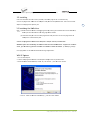
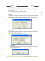
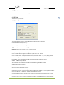
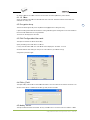
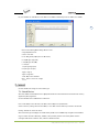
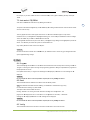
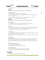
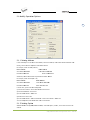
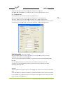
1
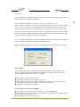
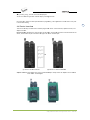
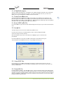
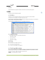
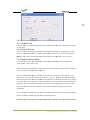
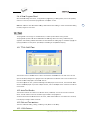
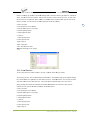
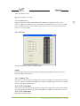
iProg /S400
Universal Programmer
User’s Manual
Aug. 2011
2 2011 NEKPUS SYSTEM
S
RESEAR
RCH CO., LTD.
©2
(http://www. nek
kpus.cn)
Info
ormation provid
ded in this docu
ument is proprieetary to NEKPUS System Research Co., Ltd.
The
e information in
n this publicatio
on is believed too be accurate in all respects at
a the time of
pub
blication, but iss subjejct to be changed withoout notice.
NEK
KPUS Systems assumes
a
no resp
ponsibility for anny errors or omissions, and disclaims
Ressponsibility for any consequenc
ce resulting froom the use of th
he information included
i
hereinn.
Tra
ademarks:
NEK
KPUS is a trademark of NEKPUS
S System Reseaarch Co., Ltd.
Win
ndows XP/7 are
e trademarks of Microsoft Corp
poration.
IBM
M is a trademark
k of IBM Corporation.
AMD is a trademarrk of Advanced Micro Devices I nc.
perty of their reespective owne
ers.
All other trademarks are the prop
iPro
og S400UXP Uniiversal Program
mmer V2.0 20
011‐09 Con
ntents
1. Inttroduction
n ……………… ……………………
……………………
……………………
………6
1.1 Harrdware Featurres
………………
……………………
……………………
……………………
………6
1.2 Software Feature
es
………………
……………………
……………………
……………………
………6
nual Conventio
on
1.3 Man
………………
……………………
……………………
……………………
………6
2. Sy
ystem requirement …………………
……………………
……………………
………7
2.1 The
e minimum re
equirements
…
……………………
……………………
……………………
………7
………
……………………
……………………
……………………
………7
2.2 Abo
out WINDOWS System
……………………………
……………………
……………………
……………………
………7
2.3 Pac
ckaging
3. Ge
etting Started …………
……………………
……………………
……………………
………7
3.1 Che
eck
…………………………………
……………………
……………………
……………………
………7
3.2 Insttalling
…………
…………………… ……………………
……………………
……………………
………8
3.3 Insttalling the USB driver
………
……………………
……………………
……………………
………8
………
……………………
………………………
……………………
……………………
………9
3.4 AC adapter
nning the softw
ware
3.5 Run
……………
……………………
……………………
……………………
………9
3.6 Seriial Number
……………………
…
……………………
……………………
……………………
………9
3.7 Erro
or Message
………………………
…
……………………
……………………
……………………
………9
4.Pro
ogramming
g and testiing ……………
………………………
……………………
……10
4.1 Prog
gramming
………
……………………
……………………
………………………
……………………
……10
4.2 Masss Program Mod
de
4.3 Testting
………………
……………………
………………………
……………………
……10
………………
……………………
……………………
………………………
……………………
……11
4.4 Dev
vice Insertion
…………………
…………………………………………
……………………
……12
5. Fille ………………
……………………
……………………
………………………
……………………
……13
5.1 Loa
ad File
…………
……………………
…………………………………………
……………………
……13
5.1.1 Frrom File Mode
…………………
……………………
…………………………………………
….13
5.1.2 To
o Buffer Mode
…………………
…………………………………………
……………………
……13
5.1.3 To
o Buffer Addre
ess
………………
……………………
……………………
……………………
……13
5.1.4 Frrom File Addre
ess
………………
……………………
……………………
……………………
……13
5.1.5 Fiile size
……………………………
……………………
……………………
……………………
……13
5.1.6 Cllear Buffer Opttion
……………
…………………………………………
……………………
……14
5.1.7 Au
uto Format De
etected
……… ……………………
……………………
……………………
……14
5.1.8 Lo
oad JEDEC (JED) File
……… ……………………
……………………
……………………
……14
5.2 Save Buffer
………
……………………
……………………
………………………
……………………
……14
ave JEDEC File
e
5.2.1 Sa
5.2.2 Sa
ave HEX File
5.3 Exitt
…………………
……………………
……………………
……………………
……14
……………………
…
…………………………………………
……………………
……14
…………………
……………………
……………………
………………………
……………………
……15
iPro
og S400UXP Uniiversal Program
mmer V2.0 20
011‐09 3 ……………………
6. Ed
dit …………………………………
……………………
……………………
……15
………
……………………
……………………
……………………
……………………
……15
6.1 Edi t Buffer
ase Edit Option
6.1.1 Ba
………………
………………………
……………………
……………………
……15
6.1.2 Fa
ast Change Buffer Address
………
……………………
…………………………………………
……………………
……16
6.1.3 Da
ata Edit
6.1.4 Fiill
…
……………………
……………………
……………………
……15
………………
…………………… ……………………
……………………
……………………
……16
……………
…………………… ……………………
……………………
……………………
……16
6.1.5 Co
opy
……………
……………………
……………………
………………………
……………………
……16
6.1.6 Se
earch
6.1.7 Ne
ext
………………
……………………
……………………
………………………
……………………
……17
6.1.8 Prrint
……………
…………………… ……………………
……………………
……………………
……17
………
……………………
……………………
……………………
……………………
……17
6.1.9 CheckSum
6.1.10
…………
……………………
………………………
……………………
……………………
……18
Show
……………………
…
……………………
………………………
……………………
……18
6.2 Encrryption Array
6.3 Editt Configuratio
on\User code
6.4 Editt E_Field
……………………
……………………
……………………
……18
……
……………………
………………………
……………………
……………………
……18
……………………
…
……………………
……………………
……………………
……18
6.5 Mod
dify Vector
7. Se
elect …………
……………………
…………………………………………
……………………
……19
……
……………………
……………………
………………………
……………………
……19
7.1 Sele
ect Device
…………………
……………………
……………………
……………………
……20
7.2 Fasst Find Device
e
7.3 Autto Select E(E)P
PROM
…………
…………………………………………
……………………
……21
8. Ru
un ………………
……………………
……………………
………………………
……………………
……21
…………
…………………… ……………………
……………………
……………………
……21
8.1 Pro
ogram
………………
……………………
…………………………………………
……………………
……21
8.2 Rea
ad
8.3 Verrify
…………………………………
……………………
……………………
……………………
……21
……
……………………
……………………
……………………
……………………
……22
8.4 Bla nk Check
…………
……………………
…………………………………………
……………………
……22
mpare
8.5 Com
8.6 Autto
………………
…………………… ……………………
……………………
……………………
……22
8.7 Sec
curity
…………
…………………… ……………………
……………………
……………………
……22
8.8 Enc
cryption
………
……………………
…………………………………………
……………………
……22
8.9 Program Configurration
TP security
8.10 OT
…………
…………………………………………
……………………
……22
……………………
…
………………………
……………………
……………………
……22
9. Se
etting ………
……………………
………………………
……………………
……………………
……22
9.1 Mod
dify Operation
n Options
……
…………………………………………
……………………
……23
9.1.1 Se
etting Address
…………………
…………………………………………
……………………
……23
9.1.2 Se
etting Option
……………………
……………………
……………………
……23
……………………
9.1.3 Au
utoInc.Set
……
……………………
…………………………………………
……………………
……24
9.1.4 Ve
erify Option
……………………
…
……………………
…………………………………………
….27
9.2 Mod
dify Parameter
9.3 Edit Auto
9.4 Project
……………… ……………………
……………………
……………………
……27
……………………………
……………………
……………………
……………………
……27
……………
……………………
…………………………………………
……………………
……27
iPro
og S400UXP Uniiversal Program
mmer V2.0 20
011‐09 4 9.4.1 Sa
ave Project
……………………
…
……………………
……………………
……………………
……28
9.4.2 Lo
oad Project
……………………
…
……………………
……………………
……………………
……28
9.5 Opttion
……………
……………………
………………………
……………………
……………………
……28
9.6 Settting Option
……………………
…
…………………………………………
……………………
……29
9.6.1 Insertion test
……………………
…
…………………………………………
……………………
……29
evice ID check
k
9.6.2 De
…………………
……………………
……………………
……………………
……29
9.6.3 Mass Production
n Mode
ow Program/Re
ead
9.6.4 Slo
…………
……………………
……………………
……………………
……29
………………
……………………
………………………
……………………
……30
10. Test
T
…………
…………………… ……………………
……………………
……………………
……30
10.1 TT
TL & CMOS Test
………………
……………………
………………………
……………………
……30
10.2 Au
uto Find Devic
ce
………………
…………………………………………
……………………
……30
10.3 Ed
dit and Test Pattern
P
……… ……………………
……………………
……………………
……30
10.3.1 Edit
E
Pattern
……………………
…
…………………………………………
……………………
……30
10.3.2 Add
A
Pattern
……………………
…
………………………
……………………
……………………
……31
10.3.3 Delete
D
Pattern
n
10.4 Se
elf-Test
…………………
……………………
……………………
……………………
……32
………
………………………
……………………
……………………
……………………
……32
10.4.1 System
S
Test
……………………
…
…………………………………………
……………………
……32
10.4.2 VCC
V
Calibration
……………… ……………………
……………………
……………………
……32
10.4.3 VPP
V
Calibration
n
……………… ……………………
……………………
……………………
……32
10.4.4 Output
O
test
……………………
…
……………………
……………………
……………………
……33
….33
11. IS
SP Progra
am Mode …
……………………
……………………
………………………
iPro
og S400UXP Uniiversal Program
mmer V2.0 20
011‐09 5 1. Introduction
The iProg Prog
grammers are affordable, reliaable, and fast universal device programmers. TThey are design
ned to
operate with the
t Intel Pentiu
um-based IBM-coompatible desk
ktop computers and laptops. Noo interface card
d is
necessary to plug
p
the module
e into a PC (thiss feature is espe
ecially handy fo
or laptop users) .The menu-driv
ven
software interrface makes the
em easy to operrate.
1.1 Hardw
ware Featu
ures
■ This progra
ammer includess a 48-pin ZIF soocket & supportts 8-pin to 48-piin DIP package device.
■ With an ad
dapter, it will su
upport from 6 p
pin to 208 pin de
evice packages like PLCC, SOIC
C,TSOP, PSOP,
BGA,QFP e.g.
e
■ USB port .
■ System Upd
date by softwarre.
1.2 Softw
ware Featurres
■ Works on WINDOWS7\XP
W
\ Vista Operatingg System.
■ User-friend
dly interfaces with
w pull-down m
menus, pop-up dialogue box an
nd help.
■ Device inse
ertion test.
■ Modify algo
orithm parametters.
■ Support alll operations, such as program, verify, blank check,
c
read, sec
cure, erase and so on.
■ Set addressses intelligently
y, such as devicce start addresss, device end ad
ddress, from buuffer address an
nd so
on.
CDS) type, INTEL
L EX16
■ Support of BINARY, Intel (linear & segmeented) HEX, Mottorola S, HOLTEK type, EMC(.C
and Tektronix (linear & se
egmented) form
mats and auto find format(exce
ept HOLTEK typee and EMC(.CDS
S)
type).
difying JEDEC fiiles, HEX files, and test vectorrs.
■ Integrated editors for mod
■ Auto selectt E(E)PROM’s manufacturer
m
annd device.
■ Select chip
p from manufacturer or individ
dual device.
■ Set auto in
ncrement.
■ IC test cap
pability for TTL and CMOS Logicc ICs and auto find
f
IC mode for unknown IC’s..
■ Open & edit and test patttern, user can aalso add their ow
wn test pattern
n.
p
■ Edit auto program.
■ Auto System Test.
■Mass Producction mode.
1.3 Man
nual Con
nvention
n
The following conventions are used in this m
manual:
iPro
og S400UXP Uniiversal Program
mmer V2.0 20
011‐09 6 The names of all keyboard ke
eys are enclosed
d in angle brack
kets,<>.For example, the Enteer (or Return) ke
ey is
shows as <ENT
TER>; the Page Up key is shownn as <PgUp>.
Unless stated otherwise, keysstrokes are not case-sensitive,, e.g.: Both ‘A’ and ‘a’ are accceptable.
hown as arrow-head”-->”.
Sub-menu is sh
7 uffer address’ iss shown as Settiing -> Device Operation -> From
For example, to use ‘from bu
m bufferaddresss. It
g’ , second seleect ‘Device Operation Options’and last select ‘From buffer
means that firrst click ‘setting
address’.
2. System require
ement
2.1 The minimum
m
re
equiremen
nts
■ An Pentium
m, or compatible clone.
■ One USB po
ort.
■ Windows 7 / XP/Vista.
■ A CD-ROM driver for installation.
d
drive for op
peration, with aat least 100 MB of spare capaciity.
■ One hard disk
■ At least 512 MB of Memory
y.
2.2 Aboutt WINDOWS
S System
We think the user
u
has already
y used WINDOW
WS operating sysstem. User must be the masterr of
Computer ope
eration and only
y then can he usse the programmer easily.
2.3 Packa
aging
■ A programm
mer
■ A USB conn
necting cable
■ CD-ROM
ut and return ass soon as possib
ble
■ A registration form, fill ou
nual
■ User’s man
■ ISP lines
pter
■ An AC adap
3. Getting
g Started
d
3.1 Check
k
Your package should include a programmer, a connecting cable,
c
a power cable
c
oran AC aadapter.
iPro
og S400UXP Uniiversal Program
mmer V2.0 20
011‐09 If your device is specific pack
kage other thann DIP, please ch
hoose an adapte
er.
3.2 Installing
Insert the insttallation disc intto a driver (CD--ROM). Installattion program will run automatiically.
Connect the programmer
p
mod
dule to the com
mputer’s USB po
ort with the pro
ovided cable. Thhen connect the
e AC
adapter to the
e programmer’ss power jack.
8 3.3 Installling the US
SB driver
Note : (1) Plea
ase install the so
oftware of iProgg programmer by
b inserting the installation discc Into CD-ROM driver,
d
befo
ore you install the
t USB driver oof iProg program
mmer module.
(2) Inse
ert USB cable po
ort vertical to tthe programmerr’s USB port when connect thee programmer to
o
heco
omputer’s communication porrt.
Connect the programmer
p
mo
odule to the co
omputer’s USB port with the provided cablee.
WINDOWS sysstem will note finding
f
new haardware and auto install the USB
U driver. If Syystem can’t fin
nd the
driver, you ca
an find it by yo
ourself. This dri
river is availablle in CD-Rom orr Defaults. (C: SS400\iprog \usb
bsys).
If the program
mmer is not dete
ected follow thee below given procedure.
p
WIN XP Syystem
1. Turn on the
e computer.
2. Connect the
e programmer module
m
to the ccomputer USB port
p
with the provided cable.
3. Show Found
d new hardware
e Wizard, searchh `No, not this time`, Press th
he <Next> buttoon.
oftware automaatically`, press the <Next> buttton.
4. Search `install the so
iPro
og S400UXP Uniiversal Program
mmer V2.0 20
011‐09 9 5. Press <Finissh>.
3.4 AC ad
dapter
For programmer with USB port, you may discconnect the pro
ogrammer with power.
ect it sometimess when the comp
puter power is low,
l
(if a laptop
p is used) or if Yo
You program for a long
You can conne
time.
3.5 Running the software
Now, turn on your
y
programme
er and run iProgg software. If you use the prog
grammer with U
USB
run software after”LINK”
a
brig
ght.
port, you must
Note: Insert th
he chip only aftter the softwaree communicatio
on check is OK.
If there are no
o error message
es after runningg the software & if the commun
nication is OK,yyou can go ahea
ad
3.6 Seriall Number
Serial No is shown at the botttom (in the cenntre) of the prog
grammer softwa
are.
3.7 Error Message
When the prog
grammer is connected with PC
C, it will be auto
o system test. If it finds any errror, it will stop
p all
options.
Communicatio
on error
A communicattion error may occur
o
if a devicee is locked in the
e programmer’s ZIF socket wheen invoking any of the
software routiines. Make sure the socket is eempty when invoking any of rou
utines. Once thhe menu is on th
he
screen, you ca
an lock the ZIF socket
s
by pullinng down the lev
ver.A communication error mayy also occur if the
t
programmer iss not connected
d with the PC poort properly, orr if the power sw
witch turns off..
If your program
mmer that had the function off update online lost its program
m, you can resu me it (for
programmer S-400UXP)
c
■ Open the cover.
iPro
og S400UXP Uniiversal Program
mmer V2.0 20
011‐09 ■ Find JP3, short
s
circuit. Co
onnect with PC and wait for co
ommunication iss OK while the LLINK LED is brig
ght.
Then take out short circuiit on JP3.
■ Enter iProg
g’s system, it will
w auto-updatee. When update is OK, exit systtem.
■ Take out USB
U connecting cable, assemblee it, enter iProg
g again.
Program Error
10 b a
A program error may occur iff the manufactuurer and device of selected chiip is wrong. Andd it May occur by
ccur by a wrongg device insertio
on. For PLD, it may
m Occur by a security chip.
damaged chip. It may also oc
c
you can ad
dd tPW to progrram successfully
y. From the main screen, use tthe mouse to click on
For some old chip,
the Setting me
enu, then click on the Modify P
Parameter sub –menu.
–
And add
d tPW.
Along with the
e development of chip techniqques, the chip algorithm param
meter gets changged which creates
problem to pro
ogram the chip. You should up
pdate the software regularly & check for updaates.
When the sock
ket is smudgy or is beyond its llife cycle? It causes loose contact. The life cyycle of the socket is
about 10 thoussand times, after which pleasee replace the so
ocket with a new
w one. Select innsertion test, itt will
inform you the
e status of the same.
s
4.P
Program
mming an
nd testin
ng
4.1 Progra
amming
Note: Insert USB cable port vertical
v
to the p
programmer’s USB
U port when connect
c
the Prog
ogrammer to the
e
ommunication port.
p
computer’s co
■ Connect th
he programmer to the computeer’s communica
ation port with the
t provided caable. Then conn
nect
the AC ada
apter or power cable
c
to the proogrammer’s pow
wer jack. And turn
t
on your proogrammer. Run the
software. Insert
I
the chip only
o
after the ssoftware commu
unication check
k is OK. And locck the device in the
programme
er’s ZIF.
■ From the main
m
screen, use
e the mouse to click on the Se
elect menu, and
d then click on tthe Device Sele
ect
sub-menu. A window named Select pops out. First selec
ct the type of device. And secoondly select the
e
correct ma
anufacturer and
d device name. Finally choose OK button.
■ The next process
p
is to load
d the data that you wish to pro
ogram into the buffer. You mayy do this by loading a
data file in
nto the buffer, by
b reading dataa into the bufferr from a masterr chip, or by typping the data into the
buffer dire
ectly.
■ Click on the Run menu fro
om the main scrreen, and select the program sub-menu.
s
Yourr data will then be
ed into the chip
p. To check if p rogramming is correct,
c
you can verify it.
programme
4.2 Mass Program
P
Mode
M
The mass mod
de is that using one programm
mer to achieve mass
m
production
n. In this mode, you
just put a deviice into socket. The system willl automatically
y detect and pro
ogram the devicce; you don’t ne
eed to
iPro
og S400UXP Uniiversal Program
mmer V2.0 20
011‐09 press any key..
ng Mass Production Mode, you sshould select the device you wa
ant to program and set the Edit Auto
Before enterin
first. For insta
ance, setting Bla
ank Check, Proggram etc.
11 After click ‘Ma
ass Production Mode’,
M
click ‘Psset’ on the right-below, selectt one of “Auto
Program” ”Verrify” ”Blank Che
eck” ”Erase”. SSelect ‘Target Count
C
enable’, then you can filll a number in “T
Target
Count”, click ‘ok’. This optio
on can makes prrogramming autto-stop when th
he number of chhips programme
ed
mber you has filled. After click ‘Prog’ button in
i the toolbar, insert
i
a device in socket. You can
reach the num
forget about the
t screen and keyboard,
k
just llook at LED on the programme
er. The glowing yellow LED indicates
that the devicce has been Prog
grammed succeessfully. Please remove the dev
vice and insert a new device in
n the
ZIF socket.The
e system will prrogram the new
w device automa
atically.
After entering
g Mass Productio
on Mode, the m
mouse and keybo
oard operation will
w be denied eexcept Auto pro
ogram
button in the toolbar.
t
Pressin
ng ‘Prog’again w
will exit Auto prrogram mold.
Note: that if you
y want Auto program
p
at norm
mal operation mode,
m
please do
o not keep Masss Production acttive.
4.3 Testin
ng
The programm
mer can test logic ICs and RAM memory device
es. The software
e test menu proovides an easy
interface for loading and editting test patterrns to test a dev
vice.Test. lib co
ontains the TTL and CMOS test
patterns.Follo
ow below given steps to test lo gic ICs and Ram
ms:
■ Place the device
d
into the ZIF socket and lock it.
■ From the main
m
menu screen, select “Testt TTL & CMOS Test”.
T
■ Enter the device
d
name in the box provideed. If the devic
ce is not found in
i the Test. lib llibrary, an error
message will
w be displayed
d. You can also sselect a device from the list viewer.
■ By clicking OK the test ressult will be disp
played.
Follow the be
elow given step
ps to test DRAM
M/SRAM.
■ From the main
m
menu screen, select “Seleect –〉Select ”,, “Type” selec
ct DRAM/SRAM.
■ Enter the device
d
name in the box. If the device is not fo
ound,
also select a device from the list viewer.
an errorr message will bbe displayed. Yo
ou can
■ Place the device
d
into the ZIF socket and lock it.
iPro
og S400UXP Uniiversal Program
mmer V2.0 20
011‐09 ■ By clicking “Prog”, the test result will bee displayed.
f
the type off an unknown chhip by selecting
g Auto find.
You can even find
For testing Ram, follow the same proceduree as for program
mming. The only
y difference is thhat there is onlly Test
in the Function Dialog.
12 4.4 Device Insertion
n
There are thre
ee ways to inserrt devices into tthe programme
er socket: normal insertion, speecial insertion, and
adapter inserttion.
Normal inserttion: Following the reference nnext to the sock
ket, always inse
ert the device innto the bottom of the
socket, oriented with the pin
n 1 located in thhe upper left co
orner. As follow plot.
10
(a) Insertio n of de
evice 93LC46
(b)) Insertion of device
d
ATMEGA88L
Adapter inserrtion: Some dev
vices may need a customized adapter.
a
Always insert the adappter into the bo
ottom
of the soc
cket. As follow p
plot.
iPro
og S400UXP Uniiversal Program
mmer V2.0 20
011‐09 5. File
This menu dea
als with data fille managementt and system intterfacing.
5.1 Load File
13 This option loa
ads a disk file in
nto the memoryy buffer.
Files loaded in
nto the program
mmer are divideed into two type
es.
For programming memory and Micro control ler chips, date file types is generally HEX or BBinary.
For programming PLD chips, the
t data file ty pe is .JED(JEDE
EC).
This command
d can be selecte
ed from the me nu, or by pressiing the hot-key <F2>.
Type in the filename and press<ENTER>, or p
press <TAB> to switch to the list of files.
w
the arrow keys,
k
and press<<Enter> to selec
ct the file.
Select a file with
If current deviice is a memory
y type device (EEPROM/EEPROM
M/SPROM/MPU/PROM/IC Card),, you
will see a Load
d File Dialog Bo
ox after you seleect a file.
5.1.1 From
m File Mod
de
This option ind
dicates which bytes
b
must be reead in the inputt files. Select th
he required form
rmat.
5.1.2 To Buffer
B
Mod
de
This option ind
dicates where the
t byte previouusly read is to be
b written. Thiss enables you too ‘build’ the me
emory
buffer from se
everal files.
5.1.3 To Buffer
B
Address
If the data rea
ad is to be copie
ed into a differrent area of the
e buffer, fill in the starting adddress here.
5.1.4 From
m File Add
dress
If only a selectted range is to be
b read from thhe input file, filll in the address that will contaiinnThe first bytte into
this box, and the
t size of the buffer
b
to be reaad.
5.1.5 File
e size
ains the buffer size.
s
By defaultt it is the same size as the dev
vice size. If you want
This box conta
to download a file into memo
ory that is diffeerent from the active
a
device siz
ze, insert the siize here.
iPro
og S400UXP Uniiversal Program
mmer V2.0 20
011‐09 5.1.6 Clea
ar Buffer Option
O
There is an op
ption Clear Buffer here. If the ooption is set to 0x00 or 0xFF, the
t whole buffeer will be filled with
0x00 states or with 0xFF state
e before load a file. If you wan
nt to load two or
o more files, yyou must set to
disable.If not, when the seco
ond file is loadeed, the first file is cleared.
5.1.7 Auto
o Format Detected
D
The software automatically
a
detects
d
the form
mat of the file that
t
is to be loa
aded(except HO
OLTEK type and
EMC(.CDS) typ
pe). If the forma
at of the file difffers from the format
f
detected, select the coorrect file format.
Data types sup
pported are Bina
ary, Intel HEX, M
Motorola S, Tekttronix HEX types, HOLTEK typee, EMC(.CDS) typ
pe and
INTEL HEX16 type. Select the
e appropriate tyype for your datta file.
5.1.8 Load JEDEC (JJED) File
If the selected
d device type is PLD, the Load JED File dialogue box will pop up. Type in thee file name and
d press
enter.
5.2 Save Buffer
B
This option letts you save the contents of thee memory buffe
er to a file.
If you wish to save the file in the default dirrectory, type in a filename and
d press<ENTER>>.
You can also change to another directory.
When the dire
ectory that you want to save thhe file to is disp
played, type in the filename annd
press<ENTER>
If the file alre
eady exists, the system will askk for confirmation to overwrite
e the existing fiile.
This command
d can be selecte
ed from the me nu, or by pressiing the hot-key <F3>.
5.2.1 Save
e JEDEC Fiile
For PLD device
es, the save JED
D file dialogue b
box will pop-up
p. It consists of Name (input linne), File (list
viewer),OK an
nd Cancel Buttons. You can indiicate the directtory and the name of the file tto be saved in the
t
input line,labe
eled Name.
e HEX File
5.2.2 Save
For ROM (E(E)PROM, SEPROM, MCU/MPU) d
device types, the
t box named Save Buffer willl be displayed.After
you input the file name and click
c
OK, the boox named Save Buffer to a file will be displayeed. This dialogu
ue box
consists of an input for From Buffer address,, another input line for Save size, buttons for File Format, an
nd the
OK and Cancell Buttons. The format
f
of the fiile that be save
ed must also be selected in thee File format are
ea by
pressing one of
o the selection buttons.
iPro
og S400UXP Uniiversal Program
mmer V2.0 20
011‐09 14 5.3 Exit
This command
d closes the programmer softw
ware and returnss to the control of operating syystem.
6. Edit
15 This option is used to edit the
e memory buffeer.
6.1 Edit Buffer
B
This option is used to edit the
e memory buffeer. The contents of the buffer will contain hexx codes.
ayed on the righht-hand side of the screen.
The equivalent ASCII is displa
he hex codes by
y clicking on thee code that has to be changed. Alternatively yyou can edit the
e ASCII
You can edit th
codes by clicking on the ASCII code to be chaanged.
This command
d can be selecte
ed from the me nu, or by pressiing the hot-key <F4>.
6.1.1 Base
e Edit Option
Edit the buffer
b
data on the
t screen withh the following keys:
→
: Move cursor
to right
←
: Move cursor to left
↑
: Move cursor
to up
↓
: Move cursor
to down
n
PgUp : Pag e up
u
PgDn : Page do
own
Home : Move cursor
c
to the be
eginning of the line
End : Move cursor
c
to the en
nd of the line
Tab : Switch the cursor betw
ween the two seections
B
Addrress
6.1.2 Fastt Change Buffer
You can enter an address you
u wish to be disp
played to skip to
t by clicking on
n the address fi eld (on the leftt-hand
side). Then typ
pe in the addresss, the cursor w
will blink at the address
a
specifie
ed in the space m
marked new address.
For ROM you can
c input 0—F. And
A for PLD youu only could input 0 and 1.
WARNING!
Input address must
m
not overlap
p.
iPro
og S400UXP Uniiversal Program
mmer V2.0 20
011‐09 6.1.3 Data Edit
This selection brings up the Fuse
F
Buffer editt windows if the
e device type iss a PLD, or the D
Data Buffer edit
window for me
emory devices. The buffer is foor 8-bit data, and
a the numbers in the Left coolumn are the
addresses of the buffer.
B
edit wind
dow, 1 is logic H
High and 0 is log
gic Low.
For the Fuse Buffer
The Data Buffe
er edit window has two edit arreas: one suppo
orts Hex code, and
a the other SSupports ASCII.
6.1.4 Fill
This selection will bring up th
he Fill buffer diialogue box. It consists
c
of the Start
S
address innput line,End ad
ddress
input line, Filll data input line
e, OK and Canceel buttons. Inpu
ut any desired data
d
to be filledd into the Fill data
input line, and
d specify the ra
ange by indicati ng the beginnin
ng and ending addresses. For the Fuse buffe
er edit
window, the data
d
will be eith
her 1 or 0.For thhe Data buffer edit
e
window, it will be a two-ccharacter HEX code.
c
6.1.5 Cop
py
This selection displays the Co
opy buffer dialoogue box. It con
nsists of the Start address inpu t line,End addrress
input line, new
w address input line, OK and Caancel buttons. Data
D
between Start address annd End address will
w be
copied to the buffer starting from New addrress.
Note: that the
e source and destination areaa must not overlap.
6.1.6 Search
This com
mmand searchess for a search sttring, which can
n be entered ass HEX codes, or as ASCII charac
cters.
Enter the search string and click OK.
iPro
og S400UXP Uniiversal Program
mmer V2.0 20
011‐09 16 6.1.7 Nex
xt
Perform the ne
ext search for the
t search strinng in ‘Search’.
6.1.8 Prin
nt
17 This selection will print buffe
er.
6.1.9 Che
eckSum
The checksum
m dialog is used for calculate chhecksums of sellected block in buffer. The
Checksums are
e calculated by next way :
BYTE - sum byy bytes to "word
d". CY flag is ignnored.
WORD - sum by
b words to "word". CY flag is iggnored.
BYTE (CY) - su
um by bytes to "word".
"
CY flag is added to result.
WORD (CY) - sum
s
by words to
o "word". CY fla g is added to re
esult.
Column marke
ed as NEG. is a negation
n
of cheecksum so, that SUM + NEG. = FFFFH.
F
Column marke
ed as SUPPL. is complement off checksum so, that
t
SUM + SUPPL. = 0 (+ carryy) Dialog checkssum
contains follow
wing items:
From address: This is a start address of blocck selected for calculating
c
chec
cksums in buffeer.
Address
efined as Byte address.
a
is de
To address: Th
his is an end add
dress of block sselected for calc
culating checkssums in buffer.
Address is defined as Byte ad
ddress.
Insert checksu
um: This is special item used foor select which kind of checksu
um will be writtten Into the buffer
when, the Calculate & insert was executed.
Insert address: This is speciall item that speccifies an addresss from the bufffer where a resuult of chosen
checksum will be written, wh
hen the Calcula te & insert wass executed. Address can not bee specified insid
de the
range <From address>
a
to <To address>. Addrress is defined as
a Byte address.
Calculate: Clicck on the button Calculate sta rts calculating checksums for selected
s
block iin buffer.No wrrites
into the buffer are executed..
Calculate & in
nsert: Click on the
t button Calcuulate & insert starts
s
calculatin
ng checksums foor selected bloc
ck in
iPro
og S400UXP Uniiversal Program
mmer V2.0 20
011‐09 d writes the cho
osen checksum into the buffer on address spe
ecified by Insertt address.
the buffer and
6.1.10 Sh
how
Switch the mo
ode of buffer da
ata view betweeen 8 bit and 16 bit view. This menu
m
indicates actual data vie
ew
mode(8 bit or 16 bit), too.
6.2 Encryyption Array
18 This Sub-menu
u will appear on
nly if the chip seelected is equip
pped with an en
ncryption array.
y.
It opens the En
ncryption Buffe
er edit windows for viewing and
d editing When reading data inn the main buffe
er will
be the Exclusivve-NORed with the encryptionn table.
The result will be displayed in the buffer.
6.3 Edit Configurati
C
ion\User co
ode
This option is available for ce
ertain devices oonly.
Option pertain
ning to the activ
ve device can b
be set.
It is only entered as HEX code
es. The result oof edit will be displayed in the buffer. It can bbe
saved with datta file.After sav
ving file and yo u can read nextt file & you nee
ed not change
configuration parameter agaiin.
6.4 Edit E_Field
E
This option is only
o
used for PL
LD. It used to ed
dit information in the area. It also
a can be editted in the buffer. The
size of E-Field is 64 bit. It inc
cludes site of seeat, fig mode, version
v
and so on.
o
6.5 Modiffy Vector
This opens the
e Vector Buffer edit window. Itt’s only used fo
or PLD. If a test vector table is included in a JEDEC
J
iPro
og S400UXP Uniiversal Program
mmer V2.0 20
011‐09 ware will load th
he test vector ttable to the bufffer automatically when the JEEDEC file is load
ded.
file, the softw
19 w
editing thhe test vector.
Refer to the following when
i
state
Z: High impedance
X: Don’tt care state
N: VCC and
a ground (outtput pins are noot tested)
H: Outpu
ut logic High (VOH)
L: Outpu
ut logic Low (VO
OL)
C: Clock
k pin
1: Input logic High (VIH)
0: Input logic Low (VIL)
<PgUp>: Page up
<PgDn>: Page down
<TAB>: Skip
S
to the nextt field
Note: that
t
it’s in the TTL voltage.
7. Select
Use this comm
mand to change the active deviice type.
7.1 Selectt Device
When this com
mmand is selecte
ed the user is p
prompted with a list of all the manufacturers
m
aand devices currrently
supported by the
t programmer.
Use the mouse
e to select a ma
anufacturer or a device.
Press <TAB> to
o skip to the ne
ext field, and <SShift-TAB> to sk
kip to the previo
ous field.
Select a device by clicking on
n it with the moouse, or use <TA
AB> and the arrrow keys to movve to the device
e.
Pressing <ENTER> will select the device.
nged, the activee memory buffe
er area is autom
matically changeed to accommo
odate
When the devvice type is chan
larger or smaller devices as necessary;
n
howeever, data previously stored in the memory buuffer remains
unchanged unttil either a deviice is read, or a file is loaded from disk.
iPro
og S400UXP Uniiversal Program
mmer V2.0 20
011‐09 a any time to cancel device seelection withoutt affecting the currently selectted device.
Click Cancel at
This command
d can be selecte
ed from the me nu or by pressin
ng the hot-key <F5>.
20 Click 'Device Info.', it will be shown three iteems:
ect, demintion of
o adapter, connnection table.
‘Adapter’--incclude the name of adapter for device you sele
'Package'--intrroduction packa
age of device seelected.
'Part number description'
d
-- in
ntroduction how
w to name the part
p
number.
7.2 Fast Find
F
Device
e
If you want to find a device quickly,
q
you cann also enter a de
evice partial number. Partial innformation will cause
a list of manuffacturers and device to be disp
played.
iPro
og S400UXP Uniiversal Program
mmer V2.0 20
011‐09 f
the device named PIC16C8
84, when type is
i E/EPROM, youu only need inp
put
For example, if you want to find
16C84.
7.3 Auto Select
S
E(E)PROM
Auto-select an
n EPROM as actiive device by reeading the devic
ce ID.
21 The system ca
an automatically
y identify certaain EPROM by th
he reading the manufacturer
m
annd the device-ID that
are burnt into the chip.
This only applies to devices that support thi s feature. If the
e device does not
n support a chhip ID And
e will be displayyed indicating this. In this case
e you should Reffer to device ch
hange.
manufacturer’’s ID, a message
This is the fasttest way to sele
ect an EPROM aas active device
e.
The programm
mer determines the pins of the device, and ap
pplies a high volltage to the Apppropriate pins on
o the
socket. It is ne
ecessary to enable the system to read the dev
vice ID.
Only used by the
t device that is lower than 332 pins.
WARNING!
i not an EPROM
M when you use
e this function. Device may gett damaged when
n the
DO NOT insertt a device that is
system appliess the high voltage.
8. Run
8.1 Progra
am
This command
d programs the device
d
in the soocket with the contents
c
of the memory bufferr.Pressing <ENTE
ER> at
‘Program’ or clicking
c
this option will begin t he programming operation. Du
uring this operattion the progress will
be displayed on
o the screen.
If the option iss successful, a ‘Program OK!’ m
message will be
e displayed, oth
herwise an errorr message will be
b
displayed.
WARNING:
ve the device until this option
n is complete, as
a it may dama
age the device..
Do not remov
8.2 Read
This command
d reads the conttents of the devvice into the me
emory buffer.
Note that afte
er data has been
n read into mem
mory, the same
e size or smallerr device type m
may
be selected without altering any data stored
d.
an be selected from
f
the menu.
This option ca
Pressing <ENTER> at or clicking the ‘Read’ sselection will be
egin the read op
peration. The
b displayed on the run-time sccreen. If the op
peration is successful, a ‘Read OK!’
progress will be
message will be
b displayed,oth
herwise an erroor message will be displayed.
WARNING:
ve the device until this option
n is complete, as
a it may dama
age the device..
Do not remov
8.3 Verifyy
This command
d verifies that the content of t he device is the
e same as the contents of the
iPro
og S400UXP Uniiversal Program
mmer V2.0 20
011‐09 er. You can use this command tto verify that a device has bee
en read, and thaat the read operation
memory buffe
was successfull.
WARNING:
ve the device until this option
n is complete, as
a it may dama
age the device..
Do not remov
22 8.4 Blank Check
This command
d verifies that the device has nnot been progra
ammed.
You can start the blank check
k operation by cclicking the opttion on the men
nu, by pressing <ENTER> when the
nu.
option is seleccted on the men
If the device is blank, a messsage ‘Blank checck OK!.’ will be
e displayed on the
t run-time vieewer screen.
d
If the device is not blank, an appropriate meessage will be displayed.
WARNING:
ve the device until this option
n is complete, as
a it may dama
age the device..
Do not remov
8.5 Comp
pare
This option co
ompares the datta in the devicee with the curre
ent data in the memory
m
buffer..
If any differen
nces are found, they will be dissplayed in the active
a
window.
8.6 Auto
This function will
w execute sev
veral functions in a sequence. Generally, it executes Blank ccheck,Program and
Verify. For a PLD,
P
it executess the Erase funcction at the beg
ginning and setss the Security bbits at the end.
This command
d can be selecte
ed from the me nu, or by pressiing the hot-key <F8>.
8.7 Securrity
This feature applies to PLDs and
a Micro contrrollers equipped
d with a security
y function. If thhe security is se
et, the
med into a chip will not be reaad correctly.
data programm
Note: Lock, Prrotect, etc also mean Security dependent on Device. After which
w
the securiity device could
d pass
blank check.
8.8 Encryyption
This applies on
nly to some Mic
cro controllers. This will progra
am the content of the encrypttion table onto the
t
encryption arrray of a chip. Th
he content of thhe encryption table
t
can be loa
aded,saved and edited. Once
encryption is completed
c
the data
d
in the maiin buffer will be
e the Exclusive--NORed data wiith the encryptiion
table.
8.9 Progra
am Configuration
This option is available for ce
ertain devices oonly.
nfiguration\User code, you cann set configurattion.
In the Edit Con
8.10 OTP security
This option is only used for th
he series of AT889C51/52. It forrbids to unprote
ect.
er running this option,
o
the deviice will not be programmed ag
gain.
Note that afte
9. Setting
This option is used to set the operation opti on for the syste
em.
iPro
og S400UXP Uniiversal Program
mmer V2.0 20
011‐09 9.1 Modiffy Operatio
on Options
23 9.1.1 Settting Addre
ess
In this window
w you can set De
evice Start Addrress, Device End Address, From
m buffer addresss and Buffer siz
ze.
Usually, device address is equ
uivalent with buuffer address.
For example, INTEL 27C128A (16K X 8)
Device addresss
Bufffer address
Start address 0000
0
0000
Froom address 0000
0 0000
End address 00
000 3FFF
Buffer size 0000
0
3FFF
Sometimes, de
evice address iss not equivalentt with buffer ad
ddress.
For example, INTEL 27C210 (64K X 16 )
Device addresss
Buffer aaddress
Start address 0000
0
0000
From ad
ddress 0000 000
00
End address 00
000 FFFF
Buffer ssize 0001 FFFF
In these cases, system will au
uto modify dataa.
(1) Device Start address > Device End addresss or Device size.
d address > Device size.
(2) Device End
(3) From Buffe
er address > Bufffer size.
(4) Buffer size
e < Device size.
(5) From Buffe
er address + Dev
vice End addresss - Device Start address > Bufffer size.
You can modiffy Buffer size to
o add buffer sizze to control data.
9.1.2 Settting Option
n
Auto Increme
ent: For E(E)PRO
OM,SPROM and M
MPU, check thiss option, to use
e it, let the cod e increment be
e
enabled.
iPro
og S400UXP Uniiversal Program
mmer V2.0 20
011‐09 t
option if yo
ou want the proogrammer to bee
ep after any op
peration.
Sound: Click this
Clear Buffer after
a
select Dev
vice: If you wannt clear buffer every time afte
er select devicee, click it.
9.1.3 AutoInc.Set
For mass production, you can
n use this optionn to set producttion series.
en a position whhich will increm
ment after IC is programmed okk.
When it is actiive, data is give
You can set ‘A
AutoInc.Start’ and ‘AutoInc.End
d’ in the bufferr, you can also set
s ‘AutoInc.Vaalue’.
The incrementt format allows increment in B
Binary, ASCII He
ex, ASCII Decima
al and Modulo-226 format.If you
u want
to change the current increm
ment data, ente r the data edit window, you ca
an change data directly.
User Define(file)
me
eans From_file m
mode.
Using the From
m_file method, serial values arre read from the user specified
d input file(s) aand written
serialization data
d
to buffer on specified adddresses.
There are two
o user options in
n dialog Serializzation for User Define(file)
D
mode: File name aand Start label.
File name
v
will be rread.
File name optiion specifies the file name fro m which serial addresses and values
The input file for From-file se
erialization musst have special format, which is described in From-file
serialization file
f format belo
ow.
Start label
l
in input fi le. The reading
g of serial values from file start
rts from defined
d start
Start label deffines the start label
label.
mited by free dissk space. Recom
mmended maxim
mal number of sserial records (iitems)
Size of serializzation file is lim
in one serializa
ation file is 10000 records. Morre records may cause
c
slower op
peration when rreading serial nu
umber
before each de
evice programm
ming cycle.
iPro
og S400UXP Uniiversal Program
mmer V2.0 20
011‐09 24 From-file seriialization file fo
ormat
From-file seria
alization input file
f has text forrmat or words format.
f
The file
e includes addreesses and arrayss of
bytes defining
g buffer addresses and data to w
write to buffer. Input file has text type formaat,which structu
ure is:
[label1] addr byte0 byte1 .. byten/
...
[labeln] addr byte0 bytte1 .. bytem , aaddr byte0 byte1 ... bytek/
\______
_____________/
_________/
\_________
|
|
b
basic
part
optional part
Example:
D/
[1] 0007FA 88 89 56 02 AB CD
[2] 0007FA 02 15 04 FA 08 3C/
[3] 0007FA E0 09 67 0B A0 C0
0/
[4] 0007FA 68 87 50 02 0B 8D/
[5] 0007FA A8 05 59 34 2B 7D
D/
[6] 0007FA 33 66 77 37 92 6D , 0006F6 44 11 22 33 99 88 77
7 66 55 16/
n - labels
label1… labeln
Labels are ide
entifiers for each line of input ffile. They are used
u
for addresssing each line oof file.
The labels sho
ould be unique within
w
the file. Addressing line
es of file means, the required sstart
label entered by user definess line in input fiile from which serial
s
values reading starts. In the
example file six
s serial values with labels "1",, "2", ... "6" are
e defined.
basic part
Basic part defines buffer address and array oof bytes to writte to buffer. Basic part must bbe always
w
to bufferr at address 7FAA.
defined after label in line. In the example, eeach value is written
optional part
Optional part defines the sec
cond array of byytes and buffer address to writte to buffer. Onne
c be defined after basic parrt of data. The line
l
with "6" lab
bel has also secoond
optional part can
value definitio
on,which is writtten to buffer aat address 6F6 and
a has size 10 bytes, i.e. the last
byte of this va
alue will be writtten to address 6FF.
addr b
address to
t write data foollowing the add
dress.
Addr defines buffer
byte0..byten,, byte0..bytem
m, byte0..bytekk Bytes arrays byte0..byten,
b
by
yte0..bytem and
ata, which are
d byte0..bytek are defining da
assigned to wrrite to buffer. Maximum
M
countt of bytes in one
e data field following the addre
ress is
64 bytes. Data
a bytes are writtten to buffer frrom address addr to addr+n.
The process off writing particular bytes to buuffer is:
byte0 to
o addr
e: 88 to 7FA
for example
byte1 to
o addr + 1
89 to 7FB
byte2 to
o addr + 2
56 to 7FC
.... ….
o addr + n
byten to
CD to 7FF
Optional part is delimited fro
om the first dataa part by charac
cter " , " (comma) and its structture is the same
e as in
iPro
og S400UXP Uniiversal Program
mmer V2.0 20
011‐09 25 the first data part, i.e. addre
ess and followinng array of data
a bytes.
Characters wiith special use::
[ ] - labels must be defined in
nside square bra
rackets
',' – character which delimiters basic part annd optional partt of data
'/' – character which is the label of end of a line
Notes:
26 ontinuous numbeers.It’s better to
t define the la
abels from 1 to 10000.
- Label names can contain co
a byte numbe
er values in inpuut file are hexad
decimal.
- All address and
- Allowed addrress value size is from 1 to 6 b
bits.
- Allowed size of data arrays in one line is inn range from 1 to
t 64 bytes. Wh
hen there are tw
wo Data arrays in one
line, the sum
m of their size in
i bytes can be maximally 80 bytes.
b
- Be careful to
o set correct ad
ddresses. Addresss must be defined inside device start and deevice end addre
ess
range. In ca
ase of address out of range, thee other serializa
ation data will be missing.
- Address for Serialization
S
is always
a
assigned to actual devic
ce organization and buffer orgaanization that control
program is usin
ng for current device.
d
If the buuffer organizatio
on is byte org.(x
x8), the Serializzation Address will
w be
byte address. If the buffer orrganization is w
wider than byte,e.g. 16 bit words (x16), the Seerialization Add
dress
will be word address.
a
User defin
nes (dll)
If user definess, a config file and
a source progrram (in the fold
der which named “user auto” uunder iProg directory)
is required. In the VC++ envirronment revise and create the
e file “userauto..dll”,and use it to replace the same
he iProg directo
ory.
name file in th
In the source program,
p
user can
c define the p
password (passw
wordinit), serial number start AAddress (addr),, the
count of byte in the serial number (cnt) andd create serial number
n
automatically (tmp).
Password (passswordinit)
In the source program,
p
“8888” is the initial p
password, user can
c revise it. Th
he default of th e longest length
h is 15
bytes.
Serial Number Start Addresss (addr)
dress to write d
data following the address. Be careful to set ccorrect
Addr deffines buffer add
addresse
es.Address mustt be defined insside device starrt and device en
nd address rangge. In case
of addre
ess out of range, the other seriialization data will
w be missing. In the source pprogram,
“7F0” is the initial addrress.The defaullt of the longest length is 4 byttes. So the rangge of
address is from 0 to 7FF
FFFFFFH.
The Count Of Byte In The Se
erial Number (ccnt)
User can defin
ne the length off serial number.. In the source program, cnt iss 5. The serial
a most. When p
password is wro
ong, cnt=0.
Number can have 512 bytes at
matically (tmp) .
Create Serial Number Autom
User can defin
ne function and create serial nuumber automatically. The seria
al number will bbe returned as string.
s
The serial num
mber must relatte to the start laabel(label). Aftter IC is program
mmed ok, the laabeladd one
automatically (label=label+1)).
For example:
Create serial number
n
which has
h 5 bytes and the expression is num=123456
6789A. Then youu can
use“sprintf(tmp,"%010x",num
m);” to return tthe result which
h expression is tmp=“1234567889A”.
iPro
og S400UXP Uniiversal Program
mmer V2.0 20
011‐09 The process off writing serial number to bufffer is: 12 to 7F0
0
34 to 7F1
....
4
9A to 7F4
9.1.4 Verify Option
Once:
Enable
e this option if yyou want the programmer
p
to do
d one verify teest at VCC.
Twice at VCC +/-5%:
Enable
e this option if yyou want the sy
ystem to do two
o verify test passses,one at VCC
C +5%,
the oth
her at VCC –5%.
e this option if yyou want the prrogrammer to do two verify tesst passes, one atVCC
a
Twice at VCC +/-10%: Enable
+10%, the
t other at VC
CC –10%.
For example,
For VCC=5.00V, you caan verify once at
a VCC=5V. Or do
d two verify teest passes,one at
a
VCC=5..25V, the other at VCC=4.75V. Or do two veriffy test passes, oone at VCC=5. 5V, the
other at
a VCC=4.5V.
9.2 Modiffy Parametter
This option ha
as been include
ed for persons with in-depth technical know
wledge of the SSpecific device
e that
has to be prog
grammed. The programming p
parameters of an unknown device can be seet here.
This option sho
ould only be use
ed when the deevice is not supp
ported by the sy
ystem. Choose a device that uses the
same programming algorithm
m as the unknow
wn device, and change
c
the para
ameters accordiing to specifica
ations
only.
evices, it can’t program
p
successsfully by the standard parameters. You can ddelay tPW, incre
ease
For the old de
VCC and VPP or
o add retry tim
mes to make it ssucceed.
Warning!
a
with th
his option, as itt can damage th
he inserted dev
vice!
DO NOT play around
9.3 Edit Auto
A
This command
d can be selecte
ed from the me nu.
This menu “Ed
dit Auto” sequences the autom
matic operationss on device.
Usually, it’s Errase, Blank Che
eck, Program, V
Verify and Securre.
9.4 Projecct
Project file wiill save the currrent environme nt.
The data to be
e saved includes:
■ The inform
mation of curren
nt device: for exxample, device type, manufacturer, pin
number,VC
CC,option/configuration settingg, buffer data, data file name. (Note that bufffer data can be
iPro
og S400UXP Uniiversal Program
mmer V2.0 20
011‐09 27 change after it is loaded. It can be differrent from the data
d
file.)
nvironment Settting: Insertion T
Test, Verify Opttion, Edit Auto and so on.
■ Program en
■ Auto Settin
ng You can store
e for further us age without settting every time
e. It could avoidd the setting errror. It
is recomme
ended to use it when mass prooduction.
Note that: the
ere is a connecttion between thhe Project file and
a the program
mmer software. It would be inv
valid
after the softw
ware is updated
d.
28 9.4.1 Save
e Project
This option letts you save the current environnment to a projject file.
9.4.2 Load Project
This option letts you load the current environnment that had
d been saved fro
om a project fille.
The data saved includes the current
c
device, option/configu
uration setting and buffer dataa and so on.
9.5 Option
S
Log file Setting
This option asssociates with ussing of Log wind
dow. All reports for Log window can be writteen into the Log file
too.
e available:
Following Log file options are
◆option No (d
default) - content of Log windoow is not copied
d to Log file, i.e
e. all reports willl Be displayed to Log
window onlyy.
◆ option New
w – create a new
w log file everyy day.
◆ option App
pend - adds Log
g window reportts into existing Log file. If file does not exist, the new file will be
created.
e:
Log file name
◆ When you check
c
the optio
on New, the logg file name is lik
ke :
report-yyyy-m
m-dd.rep
The middle
e part representing of date connsists of yyyy - year, m - month and dd - day..
Example: If to
oday is May, 29tth, 2007 then thhe log file name
e is D:\Program Files\s400\ iProog
\rep
port-2007-5-29.rrep The next daay it will create
e a new log file and its name iss
D:\P
Program Files\s4
400\ iProg \repoort-2007-5-30.re
ep
◆ When you check
c
the optio
on Append, the log file name iss :
D:\\Program Files\s400\ iProg \rep
port.rep
Load file :
g file you can chheck the button
n and select the
e file you want to browse.
If you want to browse the log
f size limit arre available too
o.
Advanced optiions about Log file
■ option Truncate log file text
t
when file ssize limit is rea
ached - when checked, the Logg file size limit is on.
It means th
hat when Log file size reaches specified value
e, the part of te
ext included in Log file will be
truncated. When the optio
on is unchecked
d, the size of Lo
og file is unlimited, respectiveely is limited by
y free
disk space only.
■ option Max
ximum Log file size specifies tthe maximum siize of Log file in kBytes.
■ option Percentage of trun
ncated text speecifies the perc
centage of Log file
f text, whichh will be truncatted
after Maxim
mum Log file siz
ze is reached. T
The higher value means more text
t
will be trunncated (remove
ed)
from Log fiile.
iPro
og S400UXP Uniiversal Program
mmer V2.0 20
011‐09 29 9.6 Settin
ng Option
9.6.1 Inse
ertion test
Check this opttion if you wantt the programm
mer to do an inse
ertion test befo
ore erasing, proogramming, veriifying
etc. the device.
9.6.2 Devvice ID check
Check this opttion if you wantt the programm
mer to check dev
vice ID before erasing,
e
program
mming etc. If th
he
device is not equipped,
e
the device
d
will causee a ‘Warning! Device
D
Code Error!’ error beforre each operation.
Note: that eve
en if device ID is bad sometimees, the device will
w still be prog
grammed. You ccan cancel it.
9.6.3 Masss Production Mode
In this mode, you
y just put a device
d
into sockket. The system
m will automatic
cally detect andd program the
device;you don’t need to pre
ess any key.
ng Mass Production Mode, you sshould select the device you wa
ant to program and set the Edit Auto
Before enterin
first. For insta
ance,setting Bla
ank Check, Proggram etc.
ass Production Mode’,
M
click ‘Psset’ on the right-below, selectt one of ‘Auto PProgram’ ‘Verify
y’
After click ‘Ma
‘Blank Check’,, then you can fill
f a number inn ‘Target Count’, click ’ok’. Th
his option can m
makes programm
ming
auto-stop whe
en the number of
o chips program
mmed reach the
e number you ha
as filled. After cclick ‘Prog’ buttton in
the toolbar, in
nsert a device in
n socket. You ccan forget aboutt the screen and
d keyboard, jusst look at LED on
o the
programmer. The
T glowing yelllow LED indicattes that the device has been programmed
p
succcessfully. Plea
ase
remove the de
evice and insertt a new device iin the ZIF socke
et. The system will
w program thhe new device
automatically.
g Mass Productio
on Mode, the m
mouse and keybo
oard operation will
w be denied eexcept Auto pro
ogram
After entering
button in the toolbar.
t
Pressin
ng ‘Prog’again w
will exit Auto prrogram mold.
ou want Auto program
p
at norm
mal operation mode,
m
please do not keep Masss Production active.
Note that if yo
iPro
og S400UXP Uniiversal Program
mmer V2.0 20
011‐09 9.6.4 Slow
w Program/Read
When standard
d reading some device, it mayy failed for prog
gramming or rea
ading fallible, ddue to The capa
ability
of device. In this
t
case, selectt ‘slow program
m/read’ if this option
o
is valid.
Note: that: wh
hen the result of
o standard read
ding is differentt from slow read
ding, it means tthat Standard re
eading
is fallible, onlyy select ‘slow read’.
10. Test
The programm
mer can test logic ICs and RAM devices, as welll as perform ve
ector testing onn PLDs.
The programm
mer provides a 74/54
7
and 4000//4500 TTL/CMO
OS logic device test library, andd memory test
algorithms. Th
he following sec
ctions describe tthe functions av
vailable for testting logic ICs annd RAMs. Applyin
ng the
input(s) speciffied in the test pattern (see beelow) and check
king for the spe
ecified output(ss).
10.1 TTL & CMOS Te
est
This selection tests TTL & CM
MOS devices. Cliick on the sub-m
menu TTL&CMO
OS test in the Teest menu. This will
open the selecct chip dialogue box. Highlight device that you
u wish to test an
nd then click on the Test button
n. The
result of test will
w be displaye
ed in the window
w Test TTL.
If the device passes
p
the test, a passed test m
message will be
e displayed. If the test fails, thhe information about
a
where it failed
d is displayed. If you want to reepeat the test, click on the Re
epeat button. O
Otherwise click on
o the
Cancel button.
10.2 Auto
o Find Deviice
This selection finds out the number of an unnknown device (TTL&CMOS). Click on the sub--menu Auto find
d
device. This will
w initiate a search for the devvice type insertted in the progrrammer.
The device name found will be
b listed in the list viewer, Listt of Detected de
evices. If the deevice can’t be found,
f
vice not found!’’
it will display a message ‘Dev
10.3 Edit and Test Pattern
P
This select is used
u
for adding, editing, or deeleting a test pa
attern in the lib
brary.
10.3.1 Edit Pattern
iPro
og S400UXP Uniiversal Program
mmer V2.0 20
011‐09 30 This selection is used for editting a test patteern in the library. When you are in the Test m
menu,click on Edit
E
Pattern. This brings
b
up the Se
elect Chip to Ed
dit dialogue box
x. It consists of Select Type inpput line, a devic
ce list
viewer, and th
he OK and Cancel buttons. Youu can enter the device number into the input line, or select from
the list viewerr. On accepting the device num
mber, the softw
ware opens the edit
e window wiith the name off the
device at the top.
t
You may now use the aboove information to edit your pa
attern.
X: Don’t care state
31 t
V: VCC (output pins are not tested)
utput pins are not tested)
G: Ground (ou
H: Output logiic High (VOH)
L: Output logicc Low (VOL)
C: Clock pin
1: Input logic High (VIH)
0: Input logic Low (VIL)
<PgUp>: Page up
<PgDn>: Page down
<TAB>: Skip to
o the next field
Note: that the
e voltage is TTL voltage.
10.3.2 Ad
dd Pattern
To test a new device that is not
n included in TTL.LIB, a new
w test pattern may
m be created..
ction brings up tthe Append dialogue
To access this function, click on Add Patternn from Edit Patttern. This selec
box, which con
nsists of IC Type
e input line, Pinn number input line, and the OK
O buttons. You can input the new
n
IC
name and num
mber of pins in the
t input lines. If the name an
nd the number of
o pins is not in the current
library,pressin
ng OK will open the XXXXXXXX edit window (X
XXXXXXXXX is the new device n ame that was
entered).You may now use th
he above inform
mation to add yo
our pattern.
X: Don’t care state
t
V: VCC (output pins are not tested)
utput pins are not tested)
G: Ground (ou
H: Output logiic High (VOH)
L: Output logicc Low (VOL)
C: Clock pin
1: Input logic High (VIH)
0: Input logic Low (VIL)
<PgUp>: Page up
iPro
og S400UXP Uniiversal Program
mmer V2.0 20
011‐09 <PgDn>: Page down
<TAB>: Skip to
o the next field
Note: that the
e voltage is TTL voltage.
10.3.3 Dele
ete Pattern
Highlight the test
t
pattern you
u wish to deletee and click on OK
O button. A me
essage box thatt is ‘Delete
pattern.’will display.
d
By click
king OK button, the test patterrn will be deleted and you cann return to the main
m
menu, & also make
m
sure that you have madee the right selec
ction. The only way to retrievee a deleted testt
pattern is to recreate a patte
ern.
10.4 Self--Test
This option pe
erforms a self-te
est on the systeem hardware.
Warning:
evice from the socket before eexecuting this command.
c
Volta
ages will be appplied to certain
Remove the de
pins,and this may
m damage the
e device.
10.4.1 Sysstem Test
This selection is used for testing pins functioon which is I/O input,
i
GND outp
put, VCC outputt,VPP output.Cllicking
Test button, syystem will auto
o test. When som
mething is wron
ng, it will stop and
a display the fault pin. If it passes
p
all tests, it will display ‘Syste
em test OK!’
10.4.2 VC
CC Calibrattion
This selection is used for testing voltage provvided for device
e. By clicking Te
est button, volttage between th
he red
pin and the blue pin should be
b about 5V or 66--6.5V (Depend
dent on program
mer).Click Stop button, it will exit.
10.4.3 VP
PP Calibrattion
VPP0 (VPP1) Calibration: 12V
1
iPro
og S400UXP Uniiversal Program
mmer V2.0 20
011‐09 32 This selectio
on is used for testing
t
voltagges provided fo
or IC to progra
am. By clickinng Test button
n,
voltage betw
ween the pale blue pin and tthe blue pin sh
hould be 12—1
12.5V. Click Sttop button & it
i will
exit.
VPP0 (VPP1) Calibration: 25V
2 or 21V
This selectio
on is used for testing
t
voltagges provided fo
or IC to progra
am. By clickinng Test button
n,
voltage betw
ween the green pin and the blue pin shou
uld be 25V. Click Stop buttoon & it will ex
xit.
10.4.4 Ou
utput test
This selection is used for testting programmeer output logic.
Note that it ne
eeds a ‘Test Board’ on socket. Test Board is a short-circuit board.
b
For exam
mple,P1 pin is
short-circuited
d with P48 pin. P2 is short-circuuited with P47 pin. By clicking Test button,it starts testing. If
I Test
Board is not on
n the socket, it will note that ‘Error! No ‘Test Board’ on the socket!’.
11. ISP Program
m Mode
FEATURES:
· Interface thrrough USB port.
· Accepts stan
ndard file forma
ats: BINARY, JED
DEC, INTEL (Exttended) HEX
· Features Tesst Vector capability and multiaarray fuse map editor
e
· Optimum pro
ogramming for each
e
individual device
· Super progra
amming speed
· Supports Win
ndows XP/7/ Vissta
· Supports
la
anguages, such as
a Chinese(Simp
plified), English
h
HOW TO USE:
1 .Insert mode
e: Please put th
he plug in the soocket.
Right the
t top row:
P29、 P28 、P
P27、 P26、 P2
25
Left th
he top row:
P20、 P21、 P
P22、 P23 、P2
24
ogrammer with USB cable. Ope
en the software and wait until the programme
er
2. Connect computer and pro
initial succcess.
3. Select the model
m
of chip and press the OK
K button. The adapter
a
interfac
ce will be shownn.
4. Connect pro
ogrammer and user
u
board withh electrical cord
ds according to adapter.
5. Run the pro
ogrammer and execute
e
your op
perations.
iPro
og S400UXP Uniiversal Program
mmer V2.0 20
011‐09 33 34 iPro
og S400UXP Uniiversal Program
mmer V2.0 20
011‐09