1
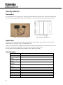
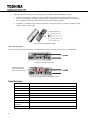
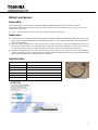
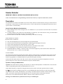
RemotEye EMD Sensor Pack User Manual Doc Number.: 63482-000 Date: April 2010 About This Manual This manual was written by the TOSHIBA Engineering and Marketing Groups. These groups are tasked with providing technical documentation for the EMD Sensors. Every effort has been made to provide accurate and concise information to you, our customer. This manual provides information on how to safely install, operate, and maintain your EMD Sensors. The information in this manual is subject to change without notice. The Toshiba International Corporation shall not be liable for direct, indirect, special, or consequential damages resulting from the use of the information contained within this manual. This manual is copyrighted. No part of this manual may be photocopied or reproduced in any form without the prior written consent of the Toshiba International Corporation. TOSHIBA is a registered trademark of the TOSHIBA Corporation. RemotEye is a registered trademark of the Toshiba International Corporation. All other product or trade references appearing in this manual are registered trademarks of their respective owners. © Copyright 2010 Toshiba International Corporation. All rights reserved. 2 Contacting TOSHIBA’s Customer Support Center TOSHIBA’s Customer Support Center can be contacted to obtain help in resolving any RemotEye sensor problem that you may experience or to provide application information. The Support Center can be reached at 877-867-8773 (toll free) or 713-466-0277. The center is open from 8 a.m. to 5 p.m. (CST), Monday through Friday. Email at: [email protected] You may also contact TOSHIBA by writing to: TOSHIBA International Corporation 13131 West Little York Road Houston, Texas 77041-9990. For further information on TOSHIBA’s products and services, please visit our website at HTTP://WWW.TOSHIBA.COM/IND. 3 Important Notice This user manual may not cover all of the variations in equipment, nor may it provide information on every possible contingency concerning installation, operation, or maintenance. The contents of this manual shall not become a part of or modify any prior agreement, commitment, or relationship between the customer and the TOSHIBA International Corporation's UPS Division. The sales contract contains the entire obligation of the TOSHIBA International Corporation's UPS Division. The warranty contained in the contract between the parties is the sole warranty of the TOSHIBA International Corporation's UPS Division, and any statements contained herein do not create new warranties or modify the existing warranty. Any electrical or mechanical modifications to this equipment without prior written consent of the TOSHIBA International Corporation will void all warranties and may void the UL/CUL listing or other safety certifications. Unauthorized modifications may also result in equipment damage or personal injury. When used on UPS supporting safety critical equipment, carefully analyze the impact of allowing remote access of the UPS control features. 4 Table of Contents About This Manual 2 Contacting TOSHIBA’s Customer Support Center 3 Important Notice 4 Introduction 7 Package Contents 8 Connect a Sensor to the EMD 9 Security Detector 10 Description 10 Application 10 Specifications 10 Vibration Sensor 11 Description 11 Application 11 Specifications 12 Water Leak Sensor 13 Description 13 Application 13 Specifications 13 Smoke Detector 14 Description 14 Application 15 Pre Install Preperations 16 Specifications 17 5 Important Safety Instructions This manual contains important instructions that should be followed during the installation, maintenance, and operation of the UPS and its batteries to assure safe and proper operation. Turn off, lockout, and tagout all power sources before connecting the power wiring to the equipment or when performing maintenance. Unauthorized personnel should not service batteries. Contact your nearest Toshiba authorized service center for battery replacement. Qualified Personnel ONLY! Qualified Personnel is one that has the skills and knowledge relating to the construction, installation, operation, and maintenance of the electrical equipment and has received safety training on the hazards involved (Refer to the latest edition of NFPA 70E for additional safety requirements). Qualified Personnel shall: Have read the entire operation manual of the system being serviced. Be trained and authorized to safely energize, de-energize, ground, lockout and tag circuits and equipment, and clear faults in accordance with established safety practices. Be trained in the proper care and use of protective equipment such as safety shoes, rubber gloves, hard hats, safety glasses, face shields, flash clothing, etc., in accordance with established safety practices. Be trained in rendering first aid. Be knowledgeable of batteries and the required handling and maintenance precautions. 6 Introduction Congratulations on the purchase of the EMD Sensor Pack for the RemotEye II and RemotEye III, Toshiba’s Uninterruptible Power Supply (UPS) system management tools. RemotEye II and RemotEye III, hereafter referred to jointly as RemotEye, supply a 10/100 base-T network card that allows network administrators to monitor UPS environmental sensors remotely via Simple Network Management Protocol (SNMP) and Hypertext Transfer Protocol (HTTP) methods. This user manual describes how to connect the sensors in the sensor package to the EMD (Environmental Monitoring Device) module, and the EMD to the RemotEye internal/external module. . The RemotEye circuit board is inserted into the option slot of the UPS and connects to the UPS via the RemotEye card edge connector. RemotEye Internal Circuit Board Installation in a UPS. RemotEye Internal Module 12VDC 12 NETWORK UPS Reset PC RemotEye External Module 7 Package Contents Listed below are the items included in the RemotEye Sensors package: 1 – P/N 1511.90005: EMD Security Detector 1 – P/N 1011.90028: Vibration Sensor 1 – P/N 1011.90025: Water Leak Detector 1 – P/N 1011.90023: Smoke Detector (110V) 1 – P/N 1011.900xx: Smoke Detector Power Cord (110V) 1 – P/N 63482: EMD Sensor Pack User Manual CD 8 Connect a Sensor to the EMD The EMD has two dry contact ports that can be used to monitor any combination of the four sensors. All four sensors provide a dry contact open/close input and connect to the EMD in a similar manner. Specific instructions regarding sensor location, mounting, and adjustments are detailed in their corresponding section. Connect a sensor to the EMD as follows: 1. Loosen the screws on EMD port labeled “1”. 2. Insert the sensor wires into to the EMD terminals labeled “1” (or “2”,) as shown in the table below and tighten the screws on the EMD. SENSOR Wire Connections Security Detector Vibration Sensor Water Sensor Smoke Detector EMD Port 1 Term. 1 Black Red White Blue Term. 2 Black Black Black Orange EMD Port 2 Term. 3 Black Red White Blue Term. 4 Black Black Black Orange 3. Install the sensor in an appropriate location. (Repeat step 1 – 3 if using a second sensor.) 4. Connect a RJ45 network cable to the port labeled “010101” on the EMD. 5. Connect the other end of the RJ45 network cable to the RemotEye module. (“PC” on the external module, “COM” for the internal module.) 6. Make sure that the RemotEye module is connected to network. Open the RemotEye web page and then select “EMD Configuration – EMD Setup”. 7. Change the status of the EMD from “Disable” to “Auto”. Check the LED (Power/Status) of EMD, the LED will flash. Set the status of Alarm-1 to “Normal Close” or “Normal Open” as required in the following sensor settings table. Repeat for Alarm 2 (if used). SENSOR Security Detector Vibration Sensor Water Sensor Smoke Detector ALARM STATUS “Normal Close” or “Normal Open” “Normal Close” “Normal Open” “Normal Closed” 8. When the sensor is triggered, the sensor state change will be displayed on the RemotEye “EMD Configuration – Comprehensive” web page which provides a overview of EMD sensor status. The alarm event will also be recorded in the RemotEye Events Log. 9. To view the UPS Events Log, click on “UPS History – UPS Events Log”. Click on the appropriate index of event activity to view the Events Log Data. 9 Security Detector Description The security detector is a proximity sensor. When a gap opens between the two sensor halves, the sensor will change state. The sensor will be triggered open by separating the two halves in any of three dimensions: up/down, back/forth, in/out. Security Detector Connected to EMD Sensor Installation Arrangement Application Security detectors are commonly used in intrusion alarm systems as door/window open sensors. However, they can be disabled if they are placed in a strong, external magnetic field. NOTE: If a security detector is dropped from more than 12 in. (30cm) onto a hard surface, or subjected to shock of more than 30G, it may alter the characteristics of the reed-switch sensor (Pull-in, Drop-out, etc.). Security detector can be mounted on Doors, Windows, Safes, Cabinets, and so forth. Specifications 10 Contact Form Form 1A (single pole, single throw) Max Contact Rating 10W Max. Switching Voltage Max Switching Current Max. Contact Resistance Min. Breakdown Voltage Reed Switch 100 Vdc Wire UL 1007 24 AWG Life Over 100,000 contacts Case ABS PA707 resin Size (each) (lxWxH) 1.14 in (L) x 0.8 in (W) x 0.6 in (H) Weight 1 oz.(28 g) 0.5 A 200 milliohm 150 Vdc MKA-14103 AT 1015 Security Detector Dimensions Vibration Sensor Description The vibration sensor is a simple normally closed counterbalanced vibration blade and contact switch that connects to the EMD. Through RemotEye the user can monitor a location for vibration. The sensor can be wired to trigger by vibration only, or by both vibration and sensor tampering. Application The vibration sensor is designed to detect forced entry through walls ceilings, windows, safes, cabinets, etc. It will initiate an alarm when the sensor is vibrated with sufficient force to trigger the adjustable reed sensor. If alarming a window, for example, the sensor should be mounted on the window frame and not the glass, as passing traffic may shake the glass enough to trigger the alarm. Adjusting Vibration Sensor Sensitivity 1. Adjust the sensor sensitivity as follows. 2. Unscrew and remove the sensor cover. 3. The Vibration Sensor sensitivity can be adjusted by turning the setscrew (see Figure below) clockwise (increase) or counter-clockwise (decrease). Vibration Sensor Adjustment Screw 4. For initial setup, decrease sensitivity by loosening (turn counter-clockwise) the setscrew until the inertial weight contact just touches the contact bead located below it. 11 5. Adjust the sensitivity of the sensor to detecting significant vibration while minimizing false triggers. Contact Pressure Range – Less than 5 g may be insufficient to prevent false triggering. More than 25 g. pressure may permanently damage the vibration blade. (If adjusting the set screw with the cover removed, be sure to gently hold the tamper switch closed to enable vibration signal triggering.) Orientation – If mounted on the ceiling or upside down, more pressure may be required to compensate for the vibration blade’s counterweight. Vibration Sensor Adjustment Range Sensor Wiring Options Decide on either simple vibration sensing, or vibration/tamper sensing, then connect the sensor wire as shown below. To EMD Wiring for Vibration Sensor Only Tamper Switch Opens When Vibration Sensor Cover Screw is Loosened To EMD Wiring for Vibration Sensor and Tamper Switch Specifications 12 Circuit Normally-close contact, momentarily open when activated Contact Pressure 1-50 grams, Best 5-25 grams, shipped with pressure of approx 6 grams Current Rating 1A at 50VDC Break Time Approx 45 ms max (at 6 grams pressure) Life Over 100,000 contacts Security Built-in tamper switch Contact Pure Silver Case ABS resin Size Weight (LxWxH) Weight 0.59 in (15 mm) x 0.83 in (21 mm) x 2.36 in (60 mm) 0.7 oz. (20 g) Water Leak Sensor Description The immersion-type water leak sensor connects with EMD. Through RemotEye the user can monitor for water accumulation. When water permeates the sensor line, the conductivity decreases causing an alarm to trigger. There are two types of water leak sensors: Type A: 1m water leak sensor connected to 1.2m electrical cable with a termination Application Common usage is areas where mission-critical equipment is being maintained, including data rooms, data centres, clean rooms, utility corridors, laboratories, telecommunication facilities, storage areas, elevator shafts, and drip pans under water-cooled equipment. The most common application for water leak detection is under raised floors. People now understand that water can come from a roof that leaks or even additional floors located above the critical equipment of concern. It is not unusual for water leak detection cable to be installed under the raised floor as well as in the ceiling above equipment. Facilities and equipment that use water-cooled technology have started to add water leak sensors to provide early warning of leaks that could potentially cause costly equipment damage and downtime. The cable can be installed around supply and return water lines to continuously monitor for leaks. Specifications Model AWL Conductor TCU Insulator PV Weave Color White, White + Red Wrap Nylon weave Power Consumption Under AC 6V Length 1 meter and 4 meter Water Leak Sensor and EMD 13 Smoke Detector IMPORTANT: READ ALL INSTRUCTIONS BEFORE INSTALLATION NOTE: The smoke detector uses a high technology electronic sensor. Do not try to repair the smoke detector yourself. Description The smoke detector connects to the EMD. The user can remotely monitor for smoke detection. This type of smoke detector is powered by 110VACwith a 9-volt battery back-up source. AC/DC smoke detectors offer added protection in the event of a power failure or a drained battery. Smoke Detector Mounting Considerations When mounting detector on the ceiling locate it at a minimum of 4” (10 cm) from the side wall and 2 feet (60.96cm) from any corner If ceiling mounting is not possible and wall mounting is permitted by your local and state codes, put wall-mounted detectors between 4 and 6 inches (10 and 15 cm) from the ceiling. Put smoke detector at both ends of a hallway if the hallway is more than 30 feet long. AVOID THESE LOCATIONS Do NOT Locate Your Detector: Near food cooking/heating areas as smoke might cause an unwanted alarm. In front of forced air ducts used for heating and air conditioning and other high air flow areas. In areas where temperatures may fall below 40℉ or above 100℉ In dusty areas, dust particles may cause the smoke detector to false alarm or fail to alarm. In very humid areas or near lavatories, moisture can cause false alarm. NEAR ELECTRICAL LIGHTS – Electrical “Noise” from electrical lights may cause nuisance alarms. Install smoke detectors at least 5 feet (1.5 meters) from such lights. FALSE ALARMS The smoke alarm is designed to minimize false alarms. Smoking will not normally set off the alarm unless smoke is blown directly into the detector. Combustion particles from cooking may set off the alarm if the detector is located close to the kitchen. Large quantities of combustion particles are generated from spills or broiling. If the detector does alarm, check for fires first. If a fire is discovered, get out and call the fire department. If no fire is present, check to see if one of the reasons listed above may have caused the alarm. Operation, Testing and Maintenance Operation: The smoke alarm is operating once the battery is connected. When products of combustion are sensed, the unit sounds a loud pulsating alarm until you pushed button once for reset. NOTE: When the battery is replaced or testing the alarm reset, the detector will resume operation after two minutes. Testing: Test the alarm by pushing test button on cover and holding button down for about 2 seconds. This will sound alarm if all electronic circuitry, horn and battery are working. If no alarm sounds, the unit has a defective battery or other failure. You can also test the alarm by blowing smoke into it. Test alarm weekly to assure proper operation. Erratic noise or low sound from alarm may indicate a defective detector. Return it for service. Warning: Test smoke detector operation at least once per week during use. 14 Maintenance:The smoke detector is virtually maintenance free. However, under dusty conditions, a vacuum hose may be used to clear the sensing chamber of dust. Do not remove smoke detector cover when vacuum is used. Battery Replacement The smoke alarm is powered by one 9V carbon-zinc battery(alkaline batteries may also be used). The battery should provide operation for at least one year under normal operating conditions. The smoke alarm has a low battery monitoring indicator which will “chirp” at approximately 20 second intervals for a minimum of 7 days. Replace battery when chirping occurs. Use only 9 volt batteries for replacement. Limitations of Smoke Detectors Smoke detectors are devices that can provide early warning of possible developing fires. However, the battery must be in good condition and installed properly. Smoke detectors cannot provide an alarm if smoke does not reach the detector. Therefore smoke detector may not sense fires starting in walls, on roofs, on the other side of a closed door, or on a different floor. The equipment should be installed in accordance with the National Fire Protection Association’s Standard 74.( NFPA, Batterymarch Park, Quincy, Mass 02269) SMOKE DETECTOR LIMITATIONS This smoke detector is not warranted to protect lives or property from fire. In addition, it is possible for the smoke detector to fail at any time. Application Install a smoke detector on the ceiling or wall closest to the detected area. Mount the smoke detector on the ceiling close to the rack or chassis. Locate a detector in every room where electrical appliances are operated (i.e. portable heaters or humidifiers). Smoke, heat and other combustion products rise to the ceiling and spread horizontally. Mounting the detector on the ceiling in the center of the room places it closest to all points in the room. When mounting detector on the ceiling locate it at a minimum of 4”(10 cm) from the side wall and 2 feet (60.96cm) from any corner. If ceiling mounting is not possible and wall mounting is permitted by your local and state codes, put wall-mounted detectors between 4 and 6 inches (10 and 15 cm) from the ceiling. Smoke Detector and EMD 15 Pre Install Preperations 1. 2. 3. 4. 5. 6. Detach cover from the base by twisting until it unlatches from the smoke alarm base. Using smoke alarm base as pattern, trace outlines of the two keyhole slots onto the mounting surface. Drill pilot hole in center of small end of each keyhole slot in mounting surface. Insert and tighten mounting screws in pilot holes until within about 1/8” from the mounting surface. Mount smoke alarm base making sure that screws are positioned in the small ends of keyholes and tighten the screws. Remove Smoke Detector from box and ensure the wire color coding labels are applied to the back of the smoke detector body and base as shown below: Smoke Detector Body – Back Smoke Detector Base – Back 7. Snap on battery wire clip and insert the battery into the Smoke Detector Body as shown above. 8. Replace cover by twisting on the mounted base until it latches. 9. Install the BLUE and ORANGE color-coded wires into the EMD as described on page 9. 10. The smoke detector requires 110Vac to operate. Either hardwire to utility power or provide a utility outlet less than 78 in. (2 m) from the detector. Install the appropriate cord connector for the detector. The wiring for the power cord is shown below. 11. Your smoke alarm is now operating. Test the alarm by pushing test button on cover and holding button down for about 2 seconds. Alarm will sound if all electronic circuitry, horn and battery are working. If no alarm sounds, the unit has a defective battery or other failure. (See Operation, Testing and Maintenance.) 16 Specifications Sensitivity Setting Comply to UL 217, EN54, CNS Operating Light Standby: Flash every 40 sec. Alarm: Flash and beep continuously Battery Abnormal: Beeps and flash every 20 sec. Sound 85dB / 3M and above Wire Color Code Wire Length Normally Open – BLUE Common – ORANGE Normally Closed - BROWN 39 in. (1 m) Ambient Temperature 14oF to 131oF (-10oC to +55oC) Material Fire-proof Plastic Dimensions 4.7 in (120 mm) Diameter x 1.5 (37 mm) H) Weight 7 oz. (200 g) Color White Effective Alert Area Building Height <4m: 150 m2 4-20m: 75 m2 17 18 INDUSTRIAL DIVISION 13131 West Little York Rd., Houston, TX 77041 Tel: 713/466-0277 Fax 713/466-8773 US 877/867-8773 Canada 800/872-2192 Mexico 01/800/527-1204 www.toshiba.com/ind 20