1
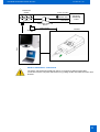
Handheld GPS/GSM Tracker
GH1201
User Manual v1.06
Handheld GPS/GSM Tracker GH1201
User Manual v1.06
CONTENTS
1.
Preface .................................................................................................................................................... 3
2.
1.1
Introduction..................................................................................................................................3
1.2
Protection of Copyrights ..............................................................................................................3
1.3
Contacts ......................................................................................................................................3
1.4
For Your Safety ...........................................................................................................................4
General Information................................................................................................................................. 7
Parts of The Set...............................................................................................................................7
Specifications of The Device ...........................................................................................................7
Electronic Specifications..................................................................................................................8
3.
Getting Started ........................................................................................................................................ 8
Inserting Sim Card And Battery .......................................................................................................8
Charging The Battery ......................................................................................................................9
4.
Installing Software ................................................................................................................................. 10
5.
Keys and Parts ...................................................................................................................................... 11
Connecting to A Pc ........................................................................................................................11
6.
Device Indicators................................................................................................................................... 12
Indicating The Status .....................................................................................................................12
Indicating a Button Push................................................................................................................12
Sound Indication ............................................................................................................................13
7.
Special Sms Requests .......................................................................................................................... 14
8.
Track Assistant Programs ..................................................................................................................... 16
Track Assistant Configuration Tool ...............................................................................................16
8.1
Configuration of Gh1201 Using a Pc.........................................................................................16
8.1.1
Track Assistant Monitoring Tool ....................................................................................................21
8.2
9.
Pin Code ...............................................................................................................................21
Monitoring of Gh1201 Using A Pc.............................................................................................21
8.2.1
General View Of The Monitoring Tool ..................................................................................22
8.2.2
Transfer of The Logged Data to A Pc ...................................................................................24
8.2.3
Geofence Zones and Their Detection...................................................................................25
8.2.4
Maps .....................................................................................................................................26
Maintenance and Repair ....................................................................................................................... 27
2
Handheld GPS/GSM Tracker GH1201
User Manual v1.06
1. PREFACE
1.1
INTRODUCTION
GH1201 is a device with built-in functions characteristic of a mobile phone and an integrated GPS receiver.
This device is intended for the surveillance and protection of people, cargo and objects. The GPS receiver
may define the current location of the device and sends this data to a person in charge or the operation
centre.
The device has a voice mail option; therefore, it may be used as a usual mobile phone.
1.2
PROTECTION OF COPYRIGHTS
All rights protected. © 2007 UAB Teltonika.
All rights are owned by the author. You may not copy, compile or transfer the present information to third
parties or distribute it without a prior written consent by UAB Teltonika.
Other products and company names mentioned in this Manual may be trademarks or names of products of
such companies.
1.3
CONTACTS
In case you have problems with the use of the product beyond your possibilities to solve it, please address
them to the Technical Assistance Centre (TAC) by e-Mail [email protected] or contact your local vendor.
We would be pleased to be of any assistance to you.
3
Handheld GPS/GSM Tracker GH1201
1.4
User Manual v1.06
FOR YOUR SAFETY
Please read these basic explanations. In disregarding them you may face danger or trespassing of existing
laws. In case you wish to have more information, please read the concise user manual.
SWITCH ON SAFELY
Do not switch on the device where it is prohibited to use a mobile phone or when such use
may cause disturbances or danger.
SAFE TRAFFIC IS THE MOST IMPORTANT
Do not infringe local legislation. When driving, use your hands for driving the car only. The
most important thing you have to think of when driving is the safety of the traffic.
DISTURBANCES
All wireless equipment may be sensitive to disturbances which may have effect on its
operation.
SWITCH OFF IN HOSPITALS
Follow all restrictions. You might need to switch off when being in the vicinity of any
medical equipment.
ŠWITCH OFF IN THE MEANS OF TRANSPORT
Follow all restrictions. Wireless equipment may cause disturbances in air traffic.
SWITCH OFF WHEN FUELING
Do not use the device in petrol stations. Do not use it in the vicinity of fuels or chemicals.
SWITCH OFF WHEN BEING IN THE VICINITY OF PLACES OF EXPLOSIONS
Follow all restrictions. Do not use the device at places where explosion works are carried
out.
PREPARE YOUR COMPUTER
Personal or portable computers to be connected to the device must comply with the
requirements of LST EN 60950-1.2003.
4
Handheld GPS/GSM Tracker GH1201
User Manual v1.06
CONNECT THE DEVICE TO THE COMPUTER
Computers to be connected to the device may be stationary or portable having an USB
connection.
CHARGER
Chargers and personal computers must comply with the requirements of LST EN 609501.2003.
USE ONLY THE BATTERIES SUPPLIED BY THE MANUFACTURER
If a battery of an improperly sort is inserted, there is a possibility for explosion or other
harms.
USE THE BATTERY SAFELY
Ensure that the battery is not immersed in the water. When storing, keep the device in a
cool, dry place.
Ensure that the battery and device are not exposed to hot surfaces or direct sunlight.
Do not mix the polarity of wires when connecting the battery to the device.
Ensure that the positive and negative poles are protected from short circuit.
When transporting, ensure that the battery is safe from metal articles and do not keep it
with metal rings, chains, etc.
Do not damage the battery with nails or sharp objects.
Do not try to charge the battery directly from a household socket. This may lead to
explosion or other harms.
To avoid mechanical damages, it is advisable to carry the equipment in a blow-proof package.
The operation environment of the device has effect on its communication quality. If the operation of the
device has been disturbed, only qualified maintenance staff may do the repair. It is recommended to deliver
the device to a repair centre or back to the factory.
Power supply chains available at a place used for connecting GH1201 must have safety devices (automatic
bipolar switch off devices) which protect from power supply excess, short circuit and failure of grounding.
The switch off device must be installed at a place which is easy to access. Its power must be consistent
with the power of the connected device, and the distance between the contacts must not be less than 3
mm.
5
Handheld GPS/GSM Tracker GH1201
User Manual v1.06
Household
socket
Protect. grounding
Phase-wire
230 V
Electricity
distributing
board
Zero-wire
Automatic switch off
device
USB connection
GH1201
PCs
Charger 2305V
USB cable
SAFELY DISCONNECT THE DEVICE
The device may be disconnected from the PC or charger by pulling out the USB
connection from the computer USB socket or by pulling out the mini USB connection from
GH1201.
6
Handheld GPS/GSM Tracker GH1201
User Manual v1.06
2. GENERAL INFORMATION
Parts of the set
GH1201 is supplied to the client packed in a cardboard box with all supplements which are necessary for
operation. The set consists of:
-
Handheld GPS/GSMTracker GH1201
-
Li-Ion or Li-Pol 750mAh battery 3.7V
-
USB – mini USB cable
-
230V – USB charger
-
Compact disk with User Manual and software
-
Printed User Manual booklet
-
Mini Screw Driwer
-
Neck Strap
Note: The manufacturer’s set does not include any SIM card which is necessary to connect to
the GSM network. A SIM card can be acquired from your local supplier of GSM services.
If any part is missing in the set, please contact the representative of the manufacturer or dealer
(www.teltonika.eu).
Specifications of the device
GPS receiver
GPS antenna
GSM frequencies
GPRS
Voice calls
Vibro call
Data transfer
Connection to a PC
Transmission of NMEA Code
Configuration
Internal memory
Buttons
Lock for keyboard
Battery
LED indicators
Dimensions (mm)
Standby time (GPS off / GPRS off)
Working time (GPS always on / GPRS off)
Working time periodically switching on GPS (time: 1 hour)
Recommended operating temperature
General operating temperature
Weight
SiRF Star III 20 channels
Internal
GSM 900/1800 MHz and 850/1900 MHz
Class 10 data
Yes
Yes
SMS or GPRS
USB
USB
SMS or USB
1MB
6
Yes
Li-Ion or Li-Pol 750mAh 3.7V
3 (Power Supply, GSM, GPS/Alarm)
91 x 44 x 19
336 hours*
6 hours*
120 hours*
0 up to 50ºC
-20 up to 60 ºC
80g
* More powerful batteries may be purchased as additional accessories
7
Handheld GPS/GSM Tracker GH1201
User Manual v1.06
Electronic specifications
Parameter
Supply voltage (DC)
Use of electric current
Battery voltage (DC)
Charger voltage (DC)
Charger electric current
Min
4.5V
2mA
3.7V
4.5V
600mA
Norm
5V
360mA
5V
Max
5.5V
2500mA (10ms)
4.2V
5.5V
1000mA
3. GETTING STARTED
Inserting SIM card and battery
All SIM cards must be kept in a save place. You may request your SIM card supplier to provide SIM cards
and information about the use of SIM card-related services. The supplier may be a service supplier, a
network operator or another seller. The SIM card must be inserted in the way as set below.
1
2
3
Note: Before removing the cover,
switch off the device and
disconnect it from the charger or
PC. The device must be always
kept and used with a cover and the
screw screwed tightly.
To insert the battery correctly, please connect its connector to the connector of the device. Afterwards hold
the battery so that the wire of the battery is directed to the left. Bend the wire carefully and put it along the
left internal side of the device. Now put the battery along the left side of the device over the wire and insert it
into the device.
8
Handheld GPS/GSM Tracker GH1201
User Manual v1.06
Charging the battery
By connecting the device to one of the USB connectors of a PC or by using the 230V – 5V charger
available in the set, it is possible to charge the internal battery of the device. For the first time, it is advisable
to charge the battery using the 230-5V charger (not via PC).
-
Connect the charger and the device by using an USB cable.
-
Plug the charger in the alternating current wall socket.
After the device is connected to the PC or alternating current wall socket, the battery charging will start.
Charging is indicated by the indicator which is present on the GH1201 (see Indicators of the device). If, for
the first time, the device has been connected with an empty battery, the indicator starts to flash just after
several minutes.
Note: Only approved batteries, chargers and supplements supplied by Teltonika should be used
with this device. By using other sorts of batteries, chargers and supplements you risk to be
deprived of all guaranties and it may also be dangerous for you and your environment.
If an unsuitable SIM card has been inserted or the device fails to detect it, the device will reload
automatically and tries to start the connection anew. If the reconnection fails, the device will show it by its
(Indicators of the device).
indicator
If the card has been inserted later, the device must be switched off and switched on again or has to be
reloaded.
Note: As with any other radio communication transmitters, do not touch
its antenna. Touching the antenna may be a cause for deterioration of
the communication quality and the device may use more energy as
usual. The antenna of the device will operate better and its battery will
decharge slower if the surface of the antenna will not be subject of
touching when in use.
9
Handheld GPS/GSM Tracker GH1201
User Manual v1.06
4. INSTALLING SOFTWARE
Drivers and software necessary for installing are filed on a compact disk supplied with the device. If you
have Internet access, please check if there is any updated software version (www.teltonika.eu). The
software version available in the device may be indicated on the splash screen.
Minimum system requirements
Operating Systems (OS)*:
MS Windows 2000 SP3 or MS Windows XP SP1
Disk space:
20 MB
Minimum screen resolution:
1024 x 768 (Full Screen)
Windows Installer V.
3.0
* We are currently working on the support of additional OS. Please contact us or your local seller for
further information.
All components required for the Track Assistant Software are part of a compact disk available in the set of
the device; however, should you fail to find it, try downloading it from the official website: www.teltonika.eu.
-
Insert the compact disk available within the set into the CD driver.
-
The installation of the software starts by activating the Setup.exe file available in the
catalogue ...\Drivers Installation Files\Setup\Track_Assistant.msi
-
Install the Track Assistant Software by referring to the information indicated within the
related windows.
10
Handheld GPS/GSM Tracker GH1201
User Manual v1.06
5. KEYS AND PARTS
6
1 – Microphone
2 – USB connector
4
5
3 – Lock for the keyboard
4 – Speaker
5 – Keyboard
8
6 – Indicators
7
7 – Switch On / Switch Off button
8 – Reset Button
1
2
Button
Alarm
State
Incoming Call
Description
Answer incoming call
On Call
Mute
On Call
End call
Incoming Call
Reject incoming call
On Call
Decrease device speaker volume
Incoming Call
Answer incoming call
On Call
Increase speaker volume
Incoming Call
Answer incoming call
On Call
End call
3
Note: (7) By a push on the (Switch On / Switch Off) button, the device can be switched on or
off.
If you wish to switch on the device, push the button shortly. After a short time the indicator
lights up and a special switch-on signal appears. GH1201 will switch immediately into the
standby mode.
If you wish to switch off the device, push the button until all three indicators light up and then
release the button. Now you will hear the special switch off signal and the indicator will light up
red/green.
If you continue to push the button even after all three indicators light up the switch off process
will be cancelled and a cancellation signal can be heard.
Connecting to a PC
GH1201 can be connected to a stationary or portable computer by using an USB data cable.
Please wait until the computer detects the new device and it will switch on automatically. Afterwards,
activate the Track Assistant Software.
11
Handheld GPS/GSM Tracker GH1201
User Manual v1.06
6. DEVICE INDICATORS
Indicating the status
If you wish to correctly find out the parameters under which the device operates, observe as carefully as
possible the status of the three indicators.
Each status indicator consists of 2-coloured lamps - one of which is indicating a failure (red) and the other
one is indicating a process in progress (green).
The red GPS/ALARM indicator, which signals at the time of Alarm (warning signal), is an exception.
Battery
Indicator Off
Device on stand-by
On
Battery fully charged
Flashing
Battery is charging
GSM
Device on stand-by
Device on stand-by
Trying to connect to
the GSM network/
Sending Data
Device is trying to find
the location
Flashing twice at a
time
GPS/ALARM
Devise did find the
location
On
SIM error /
impossible to detect
the GSM network
(when on stand-by)
Flashing
SIM error /
impossible to detect
the GSM network
Flashing twice at a
time
Battery has reached a
critical level
Both indicators on
Device is switching off
/ reloading
Alarm signal activated
(ALARM)
Indicating a button push
If GH1201 is in standby mode you can check if the device is powered with a
short button push. The standby check is possible with each button on the
keyboard. If the device is powered, the Battery LED will lighten green.
Each button on the keyboard may have a special function and can be
configured with the Track Assistant Configuration Tool. You can activate the
button function like this: After you have started to push the button, the Battery
indicator turns on but there is no sound signal; if you keep on pushing the
button, the GSM indicator turns on as well and a sound signal (a beep) can be
12
Handheld GPS/GSM Tracker GH1201
User Manual v1.06
heard. Now the button has to be released and the device will execute the
button function.
The button function can be recalled directly: If you keep on pushing the button
after the first sound signal a second signal (deeper signal, cancellation
notification) will be heard and the Battery indicator turns on. Now you can
release the button and none button function will be executed at all.
Note: If the keyboard is locked, it will not be possible to switch on the device at all. If you keep
on pushing the switch-on button, the device will switch on and off immediately. If the keyboard
is locked, the device does not react to any button push. The only exception is the Alarm button.
Please view the Track Assistant Configuration Tool explanation for further details.
Sound indication
Function activated – one short beep
Function turned off – two beeps (high and low)
Error – one short low tone beep
Device switching on – special sound signal
Device switching off – special sound signal
Outgoing SMS Notification - one short beep
Outgoing SMS Error Notification - two low tone beeps
Incoming SMS Notification – three special sound signals
Alarm Actuation Delay - two low tone beeps
13
Handheld GPS/GSM Tracker GH1201
User Manual v1.06
7. SPECIAL SMS REQUESTS
Special requests – these are special text messages which are checking the GH1201 device status and
provide response via SMS to the requesting person. Example: The requesting person sends a SMS with the
content FIX? using a Mobile Phone to GH1201 and GH1201 will send back a status SMS.
The special requests are:
FIX? – GH1201 starts the GPS receiver (not in Log Tracking mode), gets location and sends it (in case of
reception) to the requesting person. If no current coordinates will be detected GH1201 will send the latest
coordinates (date/time) from its internal memory.
Location is available
FIX! Id:GH-1201 Imei:35397601XXXXXXX
Time:YYYY.MM.DD HH:MM:SS Fix:54.1215,
25.1324 Sat:9 Op:24602 Cell:030B
Sign_Lvl:26 Bat_Lvl:94
Location is not available*
FIX! Id:GH-1201 Imei:35397601XXXXXXX
Time:YYYY.MM.DD HH:MM:SS Fix:N/A
Sat:N/A Op:24602 Cell:030B Sign_Lvl:26
Bat_Lvl:94
* N/A will only be sent if no data is available within the internal memory
INF? – GH1201 will send all information about it´s status.
INF! Id:GH-1201 Imei:
35397601XXXXXXX Time: YYYY.MM.DD
HH:MM:SS Version:HH_1.X.X.X CF:1
Live:21511 Op:24602 Cell:030B Sig_Lvl:32
Bat_Lvl:94
1
GEO? – GH1201 will check in which Geofence zone it is and if it is inside - will send the Geofence zone
name.
Device is in the Zone(s)
GEO! Id: GH-1201 Imei:
35397601XXXXXXX Time:
YYYY.MM.DD HH:MM:SS Fix: 54.1215,
25.1324 Sat:9 Bat_Lvl:94 Geo:
ZONE_NAME
Device is out of the Zone(s)
GEO! Id: GH-1201 Imei:
35397601XXXXXXX Time:
YYYY.MM.DD HH:MM:SS Fix: 54.1215,
25.1324 Sat:9 Bat_Lvl:94 Geo: N/A
LIVE? – When GH1201 receives such a request it returns back the information about how long it has been
working.
LIVE! Id:<device ID> Imei:<device IMEI>
Time:<Date Time> Fix:<Latitude,
Longitude> Live:<time in seconds how
long it is working> Bat_Lvl:<battery
charge level>
1
To get valid reponses the Geofence zones must be configured using TAMT (Track Assistant Monitoring Tool).
14
Handheld GPS/GSM Tracker GH1201
User Manual v1.06
2
MN? – NAVIGON Mobile Navigator 6 ® (Version 6.3 or higher). After receiving such a SMS GH1201 will
send back a SMS to the Mobile Phone and you will be able to see the GH1201 position within the
NAVIGON software (on the NAVIGON Map). On top you can navigate towards it while using your Mobile
Phone.
MN60;<Latitude>;<Longitude>;;;;;;;
ALARM:ON – GH1201 will enable the ALARM signal.
Location is available
Location is not available
ALARM! Id:GH-1201
Imei:35397601XXXXXXX
Time:YYYY.MM.DD HH:MM:SS Fix:54.1215,
25.1324 Sat:9 Op:24602 Cell:030B
Sign_Lvl:26 Bat_Lvl:94
ALARM! Id:GH-1201
Imei:35397601XXXXXXX Time:YYYY.MM.DD
HH:MM:SS Fix:N/A Sat:N/A Op:24602
Cell:030B Sign_Lvl:26 Bat_Lvl:94
ALARM:OFF – GH1201 will disable the ALARM signal.
Location is available
Location is not available
ALARM OFF! Id:GH-1201
Imei:35397601XXXXXXX
Time:YYYY.MM.DD HH:MM:SS Fix:54.1215,
25.1324 Sat:9 Op:24602 Cell:030B
Sign_Lvl:26 Bat_Lvl:94
ALARM OFF! Id:GH-1201
Imei:35397601XXXXXXX
Time:YYYY.MM.DD HH:MM:SS Fix:N/A
Sat:N/A Op:24602 Cell:030B Sign_Lvl:26
Bat_Lvl:94
TRACK? – GH1201 will send all collected positions to a Server via GPRS.
TRACK:ON – GH1201 will enable the „Track“ function.
TRACK ON! Id: <device ID>
Imei: 35397601XXXXXXX
Time: YYYY.MM.DD HH:MM:SS
TRACK:OFF – GH1201 will disable the „Track“ function.
TRACK OFF! Id: <device ID>
Imei: 35397601XXXXXXX
Time: YYYY.MM.DD HH:MM:SS
3
4
TRACK:ON,<P1 >,<P2 > -Starts “Track” function according to the parameters P1 and P2 (please view
footer).
2
Restriced to Mobile Phones operating on Symbian Series 60 basis. You need to have the licensed NAVIGON Mobile
Navigator 6 Software, Version 6.3 or higher , for this service. Please contact NAVIGON or Teltonika for further
information.
3
Interval of position acquisition (sec.)
4
Duration of the “Track” function (min.)
15
Handheld GPS/GSM Tracker GH1201
User Manual v1.06
8. TRACK ASSISTANT PROGRAMS
Track Assistant Configuration Tool
The Track Assistant Configuration Tool will be installed together with
the device drivers. It may be turned on by clicking Start > All Programs >
Teltonika > Track Assistant Configuration Tool in the program menu. A
special window will inform about the activation of this program.
8.1
CONFIGURATION OF GH1201 USING A PC
Please start the Track Assistant Configuration Tool. After GH1201 has been connected to the PC the
battery LED will start flashing in green.
1
Click the button Connect Tracker if you want to
configure your device directly from your PC using
an USB cable.
Click the button Connect Modem if you did
connect a Teltonika GSM modem and wish to
configure your GH1201 remotely.
2
When the device is connected to the computer,
the name of the last clicked button will change
to Disconnect Tracker, and by clicking this
button you can disconnect the device from the
computer.
If you wish to start, click the button Next.
Click the button Load Configuration if you want
to review a saved configuration file.
If you wish to switch to another configuration
window, always click the button Next.
16
Handheld GPS/GSM Tracker GH1201
3
Please read the information about the device
in the window User Registration: IMEI
Number and the Firmware Version of the
device program. Please enter the User Name,
which will be shown for this device within the
Track Assistant Monitoring Tool, the phone
number of the SIM card inserted into the
GH1201 and additional information about the
owner of the device.
Type the name of the device into the box
Device Name, which will be indicated as
device ID within all SMS messages sent by
GH1201 (please view Special SMS
Requests).
User Manual v1.06
4
If a SIM card with an activated PIN Code has
been inserted into the device, you need to
type it into the box SIM Card of the window
Security.
The PIN Code has no effect if configurations
are being rewritten but please note that if the
PIN Code is not typed, it will prevent the
device from registering into the GSM network.
If the device is not registered in the GSM
network, it will not be possible to send or
receive SMS messages and dial phone
numbers as well receiving any calls.
You can turn the list of authorised SMS
numbers on or off within the box Device. If the
list is activated, the user must type in the
subscribers’ numbers, which the device will
respond to.
If this function has been activated, it will
protect GH1201 from unwelcome queries via
SMS (i.e. Fix?, Inf? Geo? etc.) by external
persons without authorization.
If the list of authorised numbers is not
activated, everybody is allowed to send
queries via SMS to the device, and the device
will always respond to them.
17
Handheld GPS/GSM Tracker GH1201
5
You can dedicate a function for each button
on the Keyboard. Later on you can activate
this funciton by clicking on the respective
button on your GH1201. Please view the
section “Indicating a button push” in this
manual as well.
Call function allows you to call to a number
which should be typed into the Phone Number
field. Please use a format like:
+441234567890
User Manual v1.06
6
By ticking next to Vibration, you can activate
a vibro call. You can also activate a signal
warning about incoming or outgoing SMS
messages.
Choose the ringing tone of the device and set
the levels of the ring (Ring Level, 5 = loudest
level) and speaker (Speaker Level 10 =
loudest level).
If you choose the SMS function, a special
request field will appear. There you can chose
which kind of information the device will send
to the number typed into the Phone Number
field.
Alarm Off function will allow you to turn off an
Alarm which has been activated before with
the Alarm button.
Track Switch function will turn on / turn off
the track function.
Emulate Modem function will switch the
device into the modem modus when GH1201
is connected to a PC.
Please note: If you set the button Alarm
activation method to Call, window 8 of this
Configuration Tool will not open.
18
Handheld GPS/GSM Tracker GH1201
7
When you open the Alarm window you can
insert up to five SMS numbers to send Alarm
Messages. In parallel a call to one phone
number can be initiated, specified in the below
box Call Number 1.
In the box Alarm SMS Sending Interval
(sec.) you can specify the frequency of
sending SMS messages. After the specified
time passes, the device will automatically
send Alarm SMS messages. The time is
indicated in seconds.
In the box Alarm Duration Time (sec.) you
can specify the duration of the alarm. After the
specified time passes, the alarm will be
automatically turned off. The time is indicated
in seconds.
In the box Alarm Delay you can specify the
Alarm actuation time. After the specified time
passes the Alarm will be activated. During this
time period the alarm procedure can be
cancelled by pushing the defined Alarm Off
button.
Delay sound notification activates an
additional acoustic signal for this alarm
preparation phase.
Uncheck Keyboard lock valid for Alarm
button if you want the Alarm button to be
always active - even if the keybord is locked.
On top you can choose the option that the
Alarm will be combined with Vibration.
User Manual v1.06
8
You can fix the automatic data update interval
(GPS Logging Interval). If this function has
been activated, the device will activate the
GPS module after the set time. The
geographical co-ordinates will be located and
recorded into the device memory.
If the device has been requested to specify
the current location, the search may take up to
3 minutes.
If the automatic data update interval has been
activated, the device will automatically update
the data about its location within the internal
memory.
If you wish to get an immediate reply with the
last geographical co-ordinates from the
memory of the device, you need to activate
the function Log Tracking.
If this function has been activated, the device
will not start to track the new geographical coordinates (up to 3 minutes process as
indicated above) but will directly send the
newest location stored within the internal
memory.
On top you can setup the Event Based
Tracking settings. This track you can activate
by pressing a button or sending a special
SMS.
The Track Update Interval is setting the
interval in which the GPS coordinates will be
acquired.
With Track Logging Duration you can define
the time period after which the Event Based
Tracking will be finalized.
19
Handheld GPS/GSM Tracker GH1201
User Manual v1.06
battery level becomes 60% and 40% or when
the level becomes 60% and 40%, as well as
when GH1201 is 100% charged.
9
If you wish that the device will automatically
reply after a set number of rings, please
activate the function Auto Answer and
specify the number of rings.
Please specify the numbers in the below list of
numbers, to whom SMS messages notifying
about the battery level will be addressed.
11
If you wish to hear a special signal warning
each time a minute passes, activate the
function Minute Minder.
If you need to restrict the number of
subscribers that are able to call to the device,
activate the list of authorised subscribers’
numbers.
To activate, choose the function Only from
List.
After having activated this function you need
to type the numbers of subscribers into the
below boxes. Then, the device will ignore all
calling numbers which are not available in this
list.
If the function Everybody has been activated,
all subscribers’ numbers will be able to call to
the device.
In the last window you are able to choose the
function Save to File, if you wish to save the
settings on your PC.
If you wish to store the settings into your
GH1201 please choose Write to Device.
Send Through SMS will be active when a
(Teltonika) GSM Modem is connected to your
PC. If this option is selected the program will
send all configuration changes to the GH1201
device via SMS.
Click the button Finish. If you have choosen
Send Through SMS a window will open and
you need to insert the telephone number of
your GH1201 to receive the configuration
SMS.
10
Activate the function Send Notification about
Battery Level if you wish to be informed via
SMS message about the level of the battery.
After having activated this function, it will be
possible to choose either of the following:
Inform about the battery level, when the
20
Handheld GPS/GSM Tracker GH1201
8.1.1
User Manual v1.06
PIN Code
If a SIM card with an activated PIN Code has been inserted into the device, it will not be able to connect to
the GSM network and perform certain functions. Therefore, if you want the device to be fully operational,
the PIN Code must be either removed by using a Mobile Phone, if available.
Or, if you wish to enable automatic PIN Code entry by using the program Track Assistant, connect the
device to a PC and click the button Connect. When the device starts the connection to the PC, the program
will check if it hosts a SIM card and if the PIN Code is activated. If it has been activated, the program will
automatically open a window where you can insert the PIN Code. Now the PIN Code will be adopted by
GH1201 and will be always used when the device will be switched on.
Track Assistant Monitoring Tool
The Monitoring Tool is installed together with the drivers of the
device. You can switch it on witin the program menu Start > All Programs >
Teltonika > Track Assistant Monitoring Tool. A special window will inform
you about the activation of the program.
8.2
MONITORING OF GH1201 USING A PC
The Track Assistant Monitoring Tool enables the user to manage GH1201 directly from his personal or
portable computer which is connected to a GSM Modem. With a GSM Modem (i.e. Teltonika
ModemUSB/G10 ) connected to the personal or portable computer, you can receive SMS messages with
geographical coordinates from the device and immediately track it on the map.
The quantity of SMS messages is not restricted since all SMS messages available in the Modem may be
stored in the computer memory and, thus, compile the whole history of received or sent SMS messages.
By using the Track Assistant Monitoring Tool you may also request the device for special SMS queries,
which do not need to be memorised because they are already programd within the program.
By using a special tool option, you will be able to set up to ten Geofence zones and send the configurations
with SMS messages by a Modem or record it directly to the device if it is connected.
In addition, you will be able to store the data within the computer, review them or send them to another
person.
21
Handheld GPS/GSM Tracker GH1201
8.2.1
User Manual v1.06
General view of the Monitoring Tool
The tool consists of five information windows (3, 4, 5, 8, 9) and four configuration tools (1, 2, 6, 7).
1
Sytem tools menu
2
Image menu
7
3
8
User profiles
4
Map
List of available
maps
Map
5
List of Track Logs
Data on device connection status
6
Navigation
menu
9
1 – SYSTEM TOOL MENU
Hide Navigation F11 – hide the Navigation menu
Edit profiles – edit data of the user registered within the system
Monitoring – activate the map
SMS – activate the SMS window
Track Log – activate the tool to copy data from the device to read
out log data
View Location on Map – activate the tool where you can insert
the geographical co-ordinates - and the system will later show
them on the map
22
Handheld GPS/GSM Tracker GH1201
User Manual v1.06
Connect ... – connect the device to the Monitoring Tool
Device Info – review the information about the device
Connect Modem – connect a Modem to the Track
Assistant Monitoring Tool
Options ... Ctrl+O – additional settings
2 – IMAGE MENU
Connect GH1201
Hide the additional tool menu
Disconnect GH1201
Show the additional tool menu
Connect GSM Modem
Erase positions on the map
Disconnect GSM Modem
Update the list of incoming messages
Activate the map
Delete the ticked message
Activate the SMS window
Read the parameters available in the
device
Edit user profiles
Upload configuration updates to the device
Read and store Track Log
Upload complete configuration to the
device
Set Geofence
3 – USER PROFILES
After the device has been configured successfully and all necessary data has been inserted a profile will be
created for each new user. By clicking twice on the respective profile (or by clicking on the icon Edit user
profiles) the detailed profile data will be shown and can be edited.
A new record in the list of registered users appears immediately after the connection of the new device and
the introduction of the necessary data. Data on the registered users may be found by clicking twice on the
name of the selected user or choosing the button for editing user data in the image menu or system tool
menu.
4 – LIST OF AVAILABLE MAPS
A list of maps available in the PC will be displaced here. The maps are detected automatically.
5 – LIST OF TRACK LOGS
A list of previously stored Track Logs will be displaced here. By clicking on Show you can see them on the
map.
23
Handheld GPS/GSM Tracker GH1201
User Manual v1.06
6 – NAVIGATION MENU
Easy navigation between different windows.
7 – TRACK LOG FILTER
With this filter you can select the mostly needed data based on date and time, which can be reflected later
as positions on the map to be analysed. Also, it is possible to review the set Geofence zones.
8 – MAP
9 – DATA ON DEVICE CONNECTION STATUS
Here, you will be able to view the information about the current device status, no matter if it is a Modem or
GH1201. If the device is connected to the system, you will be able to see the message Device Connected,
and if it is a Modem the message will be GSM Modem Connected, as well as COM ports PORT to which
they are connected. In the system, you will also be able to see the name of the device if it has been
registered.
8.2.2
Transfer of the logged data to a PC
The device has an internal 1MB memory where it can store the history of its geographical coordinates. If
you wish to transfer this data from GH1201 to the PC, please follow these steps:
-
Activate Track Assistant Monitoring Tool.
-
Connect the device to one of the USB ports of the PC.
-
Click the button Connect.
-
Choose View > Track Log in the system menu.
The window Track Log will open.
Click the button Copy Track (an arrow to
the right of the button Copy Track allows
to choose the log data you wish to store
into the PC).
Choose the menu Event Points to
transmit the summary of all tracks which
has been taken by event (on request by
button push or SMS) from the GH1201 to
your PC.
Coose Periodical Points to show the
history of track points based on the
periodical GPS Logging (i.e. every 30
sec.)
Choose Alarm Points to show the data
stored while the warning signal Alarm has
been launched.
When the track contains too many points an Error warning will appear.
If an error window (as shown in above figure) appears during data transfer, you can click OK to resolve the
issue. Upon clicking you will have two options. These options will help to optimize the data history. The
options are as mentioned below:
24
Handheld GPS/GSM Tracker GH1201
User Manual v1.06
a) By increasing the distance between neighbouring points (picture a)
b) By increasing the maximum number of track points for display (picture b).
Data filter and image window
(a)
Data filter and image
window (b)
After having copied the data from the device, the program will inquire if you wish to save it.
The program window Track Log provides an unique possibility to filter the data read processes based on
the date and time. If you wish to see just the data pertaining to a specific period you need to type the data
and time of your choice in the boxes next to the words From and to. After a specific period is selected, click
the button Apply, and you will be able to see the data pertaining only to the selected period, which you will
be able to treat in the following way:
-
Save in the program (button Save Track).
-
Create data archive in the form of a special file (button Export).
-
View them on a Google Earth map (button Open KML File).
Note: The button Open KML File will only be activated if you install a free of charge Google
Earth map (you can download it from the link http://earth.google.com/download-earth.html).
The data saved in the program may in the map be reviewed by choosing the relevant Track Log within the
Monitoring window and by clicking the button Show.
The created special data archive may be sent to other users who will be able to review it using Track
Assistant, Microsoft Excel © or other programs supporting the *.xml file format.
Data may be deleted from the device by clicking the button Clear Log. The data stored in the program may
be deleted by clicking the button Delete; if you wish to rename it, click Rename.
8.2.3
Geofence zones and their detection
This function enables to detect the Geofence zone where the device is located. The user may set up to ten
Geofence zones and dedicate names to them.
In the settings, you can provide the name of the zone Zone Name, geographical co-ordinates of the centre
of the zone Center Longitude, Center Lantitude, radius of the zone Radius (in metres) and thickness of
the fence of the zone Fence Thickness.
If this function is activated by Enable Geofence Function, the device will check if the zone fences are
intersected. If the intersection of the zone fence (in both directions) has been detected, the device will send
a SMS message to all numbers available in the list of subscribers’ numbers under Alarm settings (Track
Assistant Configuration Tool).
If a SMS message has been sent to the device with a text GEO?, the device will detect the zone where it is
located, and if the device detects that it is located in one of the zones set, it will send the name of this zone;
if no zone is detected, the device will send an SMS message where the zone will be shown as unidentified
(N/A).
If you wish to set the zones, click the button Geofence in the image menu. If you set the zones for the first
time, the window Geofence Zones will be activated where you can enable Geofence zones Enable
Geofence Zones.
To set a zone, the following steps should be performed:
25
Handheld GPS/GSM Tracker GH1201
User Manual v1.06
2
1
3
5
6
4
7
8
1 – Enable the zone (Enable)
2 – Name the zone (Zone Name)
3 – Click Select on map to change into the map modus
4 – Place the mouse into the middle of the zone you would like to create. Hold the left mouse button and
draw the circle until the desired radius has been reached. To design the fence thickness you need to click,
with the intended distance to the defined radius, outside of the drawn circle. If you want to correct the zone
immediately please click on the map again. Now the zone will be deleted and can be created again.
5 – Confirm the selection of the zone (Done)
6 – Save the updates into GH1201 or send the settings via SMS message by clicking the button Write to
Device if a GSM Modem is connected.
7 – If you have connected modem and press button Write to Device a window will open whitch asks are
you realy want to send configuration through SMS, press button Yes to continue configuration.
8 – Insert the telephone number of your GH1201 to receive the configuration SMS.
8.2.4
Maps
The program is designed in a way that it will detect a digital map or maps if they are installed. If the user
has installed just one digital map, the map list of the Track Assistant Monitoring Tool will show the
installed map. The program is able to process these digital maps:
-
Microsoft Map Point
-
Akis
Google Earth (see Transfer of the compiled data to a PC)
26
Handheld GPS/GSM Tracker GH1201
User Manual v1.06
9. MAINTENANCE AND REPAIR
This device is a high-quality design product; therefore, it should be handled carefully. The following advice
will assist you in meeting the guarantee requirements.
-
Do not let the device get wet. In the precipitation, humidity and all sorts of liquids there may
be minerals which may be a cause of corrosion of the electricity chains. If your device got
wet, take out the battery and let the device get fully dry; afterwards, insert the battery again.
-
Do not use or keep the device in dusty and dirty places. Its moving and electronic parts
may be damaged.
-
Do not keep the device in high temperatures. High temperature may reduce the life time of
the electronic parts or damage the batteries and deform or melt some plastic parts.
-
Do not keep the device in cold environment. If the device warms up to the room
temperature, humidity may start condensing which may cause the failure of electricity
circuit boards.
-
Do not try opening the device except as specified in this User Manual.
-
Do not throw, knock or shake the device. By handling it in this way you can break internal
circuit boards and small moving parts.
-
Do not clean the device with strong chemicals, solutions or cleansing agents.
-
Do not paint the device. The paint may block the moving parts and prevent them from
operating well.
-
Use the supplied or approved antenna only when it needs to be changed. Antennas which
are not approved, their improvements or supplements may damage the device. By using
supplements which are not approved you may also infringe the legislation in the field of the
use of radio equipment.
-
The chargers must be used indoors only.
-
Before handing your device to the repair centre, make sure that its settings are stored
within the Track Assistant Configuration Tool.
All these recommendations are equally important for your device, battery, charger and any other
supplement. If any of the devices is not functioning properly, bring it for examination to the nearest
authorised repair centre.
The sign on the packaging means that the User Manual must be read before making use
of this product.
The sign on the packaging means that the electric and electronic equipment to be utilised
must be stored separately.
In case you have problems with the use of the product beyond your possibilities to solve it, please address
them to the Technical Assistance Centre by e-Mail [email protected].
27