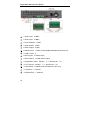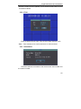
1
Digital Video Recorder User Manual Preface Attentions: The following contents are about the proper use of the product, the prevention of danger and loss of property etc.. Please be sure to abide. 1. Installation Environment ¾ Please place and use this product under the temperature of 0℃-40℃. ¾ Please do not place this product under a wet environment. ¾ Please do not place it in direct sunlight or near any heat producing appliance. ¾ Do not install it in the wet, dusty and sooty places. ¾ Please keep the level installation of this product. ¾ Please install it in a stable place. Pay attention to prevent it from falling. ¾ Do not place any other device on this product. ¾ Please install it in a well-ventilated place. Be sure not to block its air vent. ¾ It can only be used within the rated input and output range. ¾ Please do not demount this product randomly. 2.Instruction ¾ The instruction book is for reference only. The real object is the standard. ¾ The product will be updated in real time. It is subject to update without notice. ¾ For the latest program and supplementary instruction document, please contact the technical support department of the company. ¾ If there is any doubt or dispute on the product instruction, it is subject to the final interpretation of the company. This instruction book is for reference of the operation of several series of products. The specific operation of each product will not be listed one by one. Please contact the technical support department of the company if there is any doubt or question. Digital Video Recorder User Manual Content 1 Product Introduction····································································· 1 1.1 Product Summary ··········································································· 1 1.2 Main Functions ················································································ 2 1.3 Technical Data ················································································· 4 1.3.1 Technical Data of the D1 2U/1U Case Series ·························· 4 1.3.2 Technical Data of the CIF 2U Case Series····························· 10 1.3.3 Technical Data of the CIF 1.5U/1U Case Series ···················· 16 2 Product Outside Structure Introduction ································ 22 2.1 The Panel Instruction of the D1 2U/1U Case Series ···················· 22 2.2 The Panel Instruction of the CIF 2U Case Series ························· 25 2.3 The Panel Instruction of the CIF 1.5U/1U Case Series ················ 27 2.4 Remote Control Instruction ··························································· 31 2.4.1 Remote Control Instruction of 8/16 Channel ·························· 31 2.4.2 4 Remote Control Instruction ················································· 33 2.3.1 Remote Control Battery·························································· 34 2.3.2 Code Corresponding Operation of the Remote Control ········· 34 2.3.3 Turn on by Remote Control ···················································· 35 2.3.4 Disable Remote Control Operation ········································ 35 2.3.5 Abnormal Checking of the Remote Control···························· 35 3 Operating System Instruction ·················································· 36 3.1 Turn on/off DVR ············································································ 36 3.2 Preview ························································································· 36 3.3 Login ····························································································· 37 3.4 Menu Component Instruction ························································ 37 3.4.1 Screen Split ············································································ 40 Digital Video Recorder User Manual 3.4.2 Video Playback······································································· 41 3.4.2.1 File Search ······································································ 41 3.4.2.2 Search Results ································································ 42 3.4.2.3 Playback Tool Control ······················································ 43 3.4.3 Manual Recording ·································································· 45 3.4.4 PTZ Control ············································································ 47 3.5 Main Menu Introduction ································································ 48 3.5.1 Tools······················································································· 48 3.5.1.1 HDD ················································································· 49 3.5.1.2 User ················································································· 50 3.5.1.3 Default ············································································· 52 3.5.1.4 Clear ················································································ 53 3.5.1.5 Software Upgrade···························································· 54 3.5.1.6 Time ················································································· 55 3.5.1.7 Information······································································· 55 3.5.2 Setup ······················································································ 56 3.5.2.1 System Parameter ··························································· 56 3.5.2.2 Video ··············································································· 59 3.5.2.3 Alarm Input ······································································ 62 3.5.2.4 Alarm Output···································································· 64 3.5.2.5 Schedule·········································································· 65 3.5.2.6 PTZ ·················································································· 67 3.5.2.7 Motion Detection ····························································· 69 3.5.3 Video Recording ····································································· 71 3.5.4 Backup and Playback ····························································· 71 3.5.5 Log Information ······································································ 71 3.8.6 Network ·················································································· 72 3.5.6.1 LAN Configuration ··························································· 72 3.5.6.2 PPPOE Configuration ······················································ 73 3.5.6.2 DDNS Configuration ························································ 74 3.5.7 Recording Setting ··································································· 75 3.5.8 Shutdown System ·································································· 78 4 Client Operation Instruction ····················································· 79 Digital Video Recorder User Manual 4.1 The Main Page of the Video Monitoring········································ 80 4.2 Bit Stream Selection ······································································ 81 4.3 PTZ Control ··················································································· 81 4.4 Advanced Setting Box ··································································· 82 4.5 Talkback Control············································································ 83 4.6 Configuration ················································································· 84 4.6.1 Sever Parameter Configuration·············································· 84 4.6.2 Channel Parameter Configuration·········································· 85 4.6.3 Alarm Parameter Configuration ·············································· 86 4.6.4 User Configuration Information ·············································· 87 4.6.5 Others····················································································· 88 4.7 Remote Playback ·········································································· 89 5 Client Software User Manual ···················································· 91 5.1 Brief Introduction ··········································································· 91 5.1.1 System Requirements ···························································· 91 5.1.2 Agreements ············································································ 91 5.2 Install and Uninstall ······································································· 92 5.2.1 Install ······················································································ 92 5.2.2 Uninstall ·················································································· 94 5.3 Software Running·········································································· 95 5.3.1 Running and Login ································································· 95 5.3.1.1 Run the Software ····························································· 95 5.3.1.2 Register Super User ························································ 95 5.3.1.3 Login ················································································ 96 5.3.2 Software Interface Introduction ·············································· 97 5.4 Device Management ····································································· 98 5.4.1 Device Tree Configuration······················································ 99 5.4.1.1 Add Device Manually ····················································· 101 5.4.1.2 Search the Online Device within the LANs ··················· 102 5.4.2 Group Tree Configuration····················································· 104 Digital Video Recorder User Manual 5.5 Image Preview ············································································ 107 5.5.1 Preview by Non-cruise in Turn ············································· 107 5.5.2 Preview by Cruise in Turn ···················································· 108 5.5.3 Preview Control ···································································· 108 5.5.4 Sound Control ······································································ 108 5.5.5 Other Functions ···································································· 109 5.6 PTZ Control ················································································· 109 5.6.1 PTZ Control ·········································································· 109 5.6.2 Track ····················································································· 109 5.6.3 Preset Point Setting ····························································· 109 5.6.4 Cruise ··················································································· 110 5.6.5 Screen Adjustment ······························································· 110 5.7 Recording and Playback ····························································· 110 5.7.1 Client Local Recording ························································· 110 5.7.2 Remote Playback ································································· 111 5.7.2.1 Remote Video File Search ············································ 111 5.7.2.2 Remote File Playback ··················································· 112 5.7.2.3 Remote File Download ·················································· 113 5.7.2.4 Playback Control ··························································· 113 5.7.3 Local Playback ····································································· 113 5.8 Server-side Configuration ··························································· 114 5.9 Client Configuration····································································· 115 5.9.1 Local Configuration ······························································ 115 5.9.2 Recording Configuration ······················································ 116 5.9.2.1 Video Storage Path························································ 116 5.9.2.2 Plan Recording ······························································ 117 5.9.3 Alarm Link············································································· 117 5.10 Log ···························································································· 118 6 Frequently Asked Questions and Maintenance················· 119 6.1 Frequently Asked Questions ······················································· 119 6.2 Maintenance················································································ 128 Digital Video Recorder User Manual 1 Product Introduction 1.1 Product Summary This device is a digital monitoring and recording product specially designed for the security field. It adopts standalone processor and standalone Linux operating system. The device combines with the latest technologies in the IT field, such as video and audio compression/decompression, large capacity HDD record, TCP/IP network etc.. The code is embedded in the FLASH chip, which makes the system running more steadily. This device has both features of digital video and audio recording(DVR) and digital video and audio server(DVS). It can not only work locally and independently but also compose of a powerful security monitoring net with networking. With the use of professional network video surveillance platform (network) software, it can fully reflect its strong networking and remote monitoring capability. It can be used for the security protection in the fields of banking, telecommunications, electronic power, justice, traffic, residential, factory, warehouse, water conservancy facilities and other areas and departments. 1 Digital Video Recorder User Manual 1.2 Main Functions Note: The following functional characteristics will be different due to the different series of products and their different hardware versions. 1.2.1 Real-time Monitoring It is with analogue video output port, VGA port. It can realize the monitoring function through the monitor or display. It supports simultaneous TV and VGA output. 1.2.2 Storage Function It adopts special format to save data which cannot be tampered with and will be secured. 1.2.3 Compression Method It supports multi-channel audio and video signal. The audio and video signal of each channel is compressed in real time by independent hardware. The sound and image keep stabilized synchronization. 1.2.4 Backup Function It backups through USB port(such as common U disk, mobile hard disk, SATA Combo etc.) The client computer can download and backup the files on the hard disk via the internet. 1.2.5 Video Play Function Each channel can realize independent and real-time recording, while retrieval, reverse play, network monitoring, video search and download etc. can realize simultaneously. 2 Digital Video Recorder User Manual Multiple playback modes: slow forward, fast forward, reverse play and frame-by-frame play. When playing back the video, the exact time of the event can be displayed. You can choose any area of the screen and enlarge it partly. 1.2.6 Network Operation Function Through the internet, you can realize remote and real-time monitoring, remote video search and playback, and remote PTZ control. 1.2.7 Alarm Link Function It is with multi-channel relay switching alarm output, facilitating alarm link and on-site lighting control. Alarm input and alarm output ports are both with protection circuit which make sure that the main device will not be damaged. 1.2.8 Communication Port With RS485 port, realizing alarm input and PTZ control. With standard Ethernet port, realizing network remote access function. 1.2.9 PTZ Control Support the PTZ decorder which communicates through RS485. Can expand multiple decoding protocols, facilitating the realization of PTZ and dome camera control. 1.2.10 Intelligent Operation Mouse operation function. For the same settings on the menu, you can copy and paste quickly. 3 Digital Video Recorder User Manual 1.3 Technical Data 1.3.1 Technical Data of the D1 2U/1U Case Series 1 System Device Parameter D1 2U 16CH D1 2U 8CH D1 1.5U 4CH Main Processor High performance industrial embedded microcontroller Operating System Embedded LINUX Multi-tasking operation, simultaneous System multi-channel recording, simultaneous video Resources playback and simultaneous network operation. Operation User-friendly graphical menu conversation Interface interface. Input Device Input Method Shortcut Function Front panel buttons, mouse operation, remote control operation. Number, English, mark, Chinese input can be expanded. For the same settings on the menu, you can copy quickly; commonly used functions such as screen split are listed when right-click menu; double-click mouse to switch screen directly. Image H.264 Compression Compression Standard Audio ADPCM Compression 16 channel composite video (NTSC/PAL) BNC(1.0VP-P,75Ω) Video Input Video 8 channel composite video (NTSC/PAL) BNC(1.0VP-P,75Ω) 4channel composite video (NTSC/PAL) BNC(1.0VP-P,75Ω) 1 channel PAL/NTSC,BNC(1.0VP-P,75Ω) Video Output composite video signal output 1 channel VGA output 4 Digital Video Recorder User Manual Support TV/VGA video output simultaneously. 2 Device Parameter D1 Video Resolution Bit Stream Video D1 2U 16CH D1 2U 8CH D1 1.5U 4CH PAL(704x576) format total recording resources is 400/200/100 frames and each channel can realize independent hardware compression at the speed of 25 frames(adjustable) per second. NTSC(720x480) format total recording resources is 480/240/120 frames and each channel can realize independent hardware compression at the speed of 30 frames(adjustable) per second. 64Kbps~2Mbps(adjustable) Video Standard PAL(625 TVL, 50fields/second, NTSC(525 TVL, 60fields/second) Video Recording Speed Real-time mode: PAL each channel 1 frame/second-25 frames/second adjustable; NTSC each channel 1 frame/second-30 frames/second adjustable; Screen Split Monitor and Cruise in Turn Image Resolution Image Quality Area Blocks Screen Screen Screen 1, 4, 9,16 1, 4, 9 1, 4 Support monitor and cruise in turn functions including alarm, dynamic monitoring and timing control. PAL/NTSC: Real-time monitoring D1 704×576/720×480 Video playback channel 1/16: D1: 704×576/720×480 Half D1: 704×288/720×240 CIF: 352×288/ 360×240, Support double-bit stream function Image quality is adjustable by 6 levels. Within the full screen, one area protection at any size can be set. Support 2 area blocks. D1 1.5U 4ch can set 4 area blocks. 5 Digital Video Recorder User Manual Screen Information 3 Device Parameter Channel information, time information, confidential coverage of area. D1 2U 16CH D1 2U 8CH D1 1.5U 4CH The channel name, recording status, channel lock status, video loss status, motion detection Channel Status Display status etc. can be displayed at the lower left Video Audio corner of the channel screen. Set the hue, brightness, contrast, saturation, Color Setting and gain of the video input signal of each channel 4 channel 16 channel 8 channel 200-2000mV 200-2000mV 200-2000mV Audio Input 10KΩ(BNC) 10KΩ(BNC) 10KΩ(BNC) 1 channel audio output 200-3000mv 5KΩ Audio Output (BNC) Voice Talkback HDD HDD 8 SATA ports inside; can connect 8 HDDs 2 SATA HDDs HDD Space Audio: PCM 28.8M bytes/hour Consumption Video: 56~900M bytes/hour Recording Mode Recording 1 channel voice talkback input 200-3000mv 10KΩ(BNC) Manual recording, motion detection recording, timing recording and alarm recording. Cycle Way of Support hard disk cycle recording. Recording Searching video according to time, type and and Playback Video Search channel number. Playback Mode 6 Multiple kinds of slow forward rates, multiple kinds of fast forward rates, manual single-frame play, reverse play etc. Digital Video Recorder User Manual 4 channel mode and full channel mode can be chosen. When choose 4 channel mode, it Multi-channel support 1-4 channel simultaneous video play Playback back; when choose full channel mode, playback according to the actual channel number. Screen Zoom 4 Device Parameter Storage Function Backup Way Network Function Network Control Dynamic Detection and Alarm Input Motion Detection Video Loss External Alarm Playback screen can be switched freely between adaptive window state/full screen state. D1 2U 16CH D1 2U 8CH D1 1.5U 4CH Support common HDD storage backup. Support external USB storage device(such as common U disk, mobile HDD). Support network download storage. Remote access the monitoring screen of the front-end channel. Visit and set the system parameters through network client software and browser. Realize remote maintenance through client or browser network upgrade program. Check the alarm information including external alarm, motion detection and video loss etc. through network. Support network PTZ control. Support recording files download storage and video playback. Matching with related softwares(multi-device version client), it can realize multiple devices sharing information with network connection. Double-duplex transparent SATA. Network alarm input and output. Voice talkback Area setting: Every screen can set any detection area freely; sensitivity detection setting: the area can set multi-level sensitivity; can link video or link external alarm. Can link external alarm output. Can link video or link external alarm during the set period of time. 7 Digital Video Recorder User Manual You can enable or disable an alarm input Manual Alarm channel. It can analog and generate alarm signal and Control output to an alarm output channel. Alarm Input 16/8/4 channel alarm input(choose the alarm generation type by setting normally open or normally closed switch) Alarm Output 4/2/1 channel relay output Alarm Relay 5 Port Device Parameter USB Port Network Port RS485 RS232 HDD Information System Information Log Search System Version User Management User Manageme nt Password Security Protection Program Upgrade 8 30V DC 2A,125V AC 1A(link output) D1 2U 16CH D1 2U 8CH 3 USB ports RJ45 10/100/1000M self-adapt Ethernet port D1 1.5U 4CH 2 USB ports RJ45 10/100M PTZ control port; support multiple protocals. Used for common SATA debugging (non-standard fixed) Hard disk usage and other related information display. Display up to 1024 system logs and support log information search by time and type. Display recording channel number, alarm input and output channel number, system version number, release date etc. Multi-level user management. Multi-level management mode, unified management of the local, SATA and network users; special user authority can be set. Support user and group adding and authority modification; the maximum number of the user and group is 8. Support password modification; the user who has user management authority can set the password for other users. Through IE, client or USB disk Digital Video Recorder User Manual Log out and Shutdown Login using password in order to ensure the security. User-friendly menu conversation when the system menu is closed: provide options of menu user log out, device shutdown and device restart etc. You can set shutdown authority, ensuring that the user who has authority shuts down the device. 6 Device Parameter D1 2U 16CH D1 2U 8CH AC100~240V 50+2% Hz power 300W can be provided) Power Supply (maximum Power 25W(without Consumption HDD) General Parameter Operating Temperature 0℃~+55℃ Operating Humidity 10%~90% Atmospheric Pressure 86kpa~106kpa Dimension 2U standard chassis, 440x450x90mm Weight 7.4KG (without HDD) Installation Method 22W(witho ut HDD) D1 1.5U 4CH DC12V5A 15W(without HDD) industrial1.5U standard chassis, 350x240x70mm 1.7KG (without HDD) Rack-mount, desktop installation 9 Digital Video Recorder User Manual 1.3.2 Technical Data of the CIF 2U Case Series 1 System Device Parameter CIF 2U 16CH Main Processor High performance industrial embedded microcontroller Operating System Embedded LINUX System Resources Multi-tasking operation, simultaneous multi-channel recording, simultaneous video playback and simultaneous network operation. Operation Interface User-friendly graphical menu conversation interface. Input Device Front panel buttons, mouse operation, remote control operation. Input Method Number, English, mark, Chinese input can be expanded. Shortcut Function For the same settings on the menu, you can copy quickly; commonly used functions such as screen split are listed when right-click menu; double-click mouse to switch screen directly. Image H.264 Compression Compression Standard Audio Compression 10 CIF 2U 8CH ADPCM Digital Video Recorder User Manual Video Input 16 channel composite video (NTSC/PAL) BNC(1.0VP-P,75Ω) 8 channel composite video (NTSC/PAL) BNC(1.0VP-P,75Ω) 1 channel PAL/NTSC,BNC(1.0VP-P,75Ω) composite video signal output Video Video Output 1 channel VGA output Support simultaneous TV/VGA video output. 2 Device Parameter D1 Video Resolution Video Bit Stream CIF 2U 16CH CIF 2U 8CH PAL(352x288) format total recording resources is 400/200 frames and each channel can realize independent hardware compression at the speed of 25 frames(adjustable) per second. NTSC(360x240) format total recording resources is 480/240 frames and each channel can realize independent hardware compression at the speed of 30 frames(adjustable) per second. 64Kbps~2Mbps(adjustable) Video Standard PAL(625 TVL, 50fields/second, NTSC(525 TVL, 60fields/second) Video Recording Speed Real-time mode: PAL each channel 1 frame/second-25 frames/second adjustable; NTSC each channel 1 frame/second-30 frames/second adjustable; Screen Split Monitor and Cruise in Turn Screen 1, 4,8, 9,16 Screen 1, 4,8, 9 Support monitor and cruise in turn functions including alarm, dynamic monitoring and timing control. 11 Digital Video Recorder User Manual Image Resolution PAL/NTSC: Real-time monitoring D1 704×576/720×480 Video playback channel 1/16: CIF: 352×288/ 360×240, QCIF 176×144/180×120 Support double-bit stream function, auxiliary bit stream resolution QCIF 176×144/180×120 Image Quality Area Blocks Within the full screen, one area protection at any size can be set. Support MAX 4 area blocks. Screen Information Channel information, time information, confidential coverage of area. 3 Device Parameter Video Channel Status Display Color Setting Audio Input Audio Audio Output Voice Talkback HDD HDD Recording 12 Image quality is adjustable by 6 levels. HDD Space Consumptio Recording Mode CIF 2U 16CH CIF 2U 8CH The channel name, recording status, channel lock status, video loss status, motion detection status etc. can be displayed at the lower left corner of the channel screen. Set the hue, brightness, contrast, saturation, and gain of the video input signal of each channel. 16 channel 200-2000mV 10KΩ (BNC) 8 channel 200-2000mV 10KΩ(BNC) 1 channel audio output 200-3000mv 5KΩ (BNC) 1 channel voice talkback input 200-3000mv 10KΩ(BNC) 4 SATA ports inside; can connect 4 HDDs Audio: PCM 28.8M bytes/hour Video: 56~300M bytes/hour Manual recording, motion detection recording, timing recording and alarm recording. Digital Video Recorder User Manual and Playback Cycle Way of Recording Video Search Playback Mode Support hard disk cycle recording. Searching video according to time, type and channel number. Multiple kinds of slow forward rates, multiple kinds of fast forward rates, manual single-frame play, reverse play etc. 4 channel mode and full channel mode can be chosen. When choose 4 channel mode, it Multi-channel supports 1-4 channel simultaneous video play back; when choose full channel mode, Playback playback according to the actual channel number. Playback screen can be switched freely Screen Zoom between adaptive window state/full screen state. 4 Device Parameter Storage Function Backup Way Network Function Network Control CIF 2U 16CH CIF 2U 8CH Support common HDD storage backup. Support external USB storage device(such as common U disk, mobile HDD). Support network download storage. Remote access the monitoring screen of the front-end channel. Visit and set the system parameters through network client software and browser. Realize remote maintenance through client or browser network upgrade program. Check the alarm information including external alarm, motion detection and video loss etc. through network. Support network PTZ control. Support recording files download storage and video playback. Matching with related softwares(multi-device version client), it can realize multiple devices sharing information with network connection. Double-duplex transparent SATA. Network alarm input and output. Voice talkback 13 Digital Video Recorder User Manual Motion Detection Video Loss Dynamic Detection and Alarm Input External Alarm Area setting: Every screen can set any detection area freely; sensitivity detection setting: the area can set multi-level sensitivity; can link video or link external alarm. Can link external alarm output. Can link video or link external alarm during the set period of time. You can enable or disable an alarm input Manual Alarm channel. It can analog and generate alarm signal and Control output to an alarm output channel. Alarm Input 16/8/4 channel alarm input(choose the alarm generation type by setting normally open or normally closed switch) Alarm Output 4/2 channel relay output Alarm Relay 5 Port Device Parameter USB Port Network Port RS485 RS232 HDD Information System Information Log Search System Version 14 30V DC 2A, 125V AC 1A(link output) CIF 2U 16CH CIF 2U 8CH 3 USB ports RJ45 10/100M self-adapt Ethernet port PTZ control port; support multiple protocals. Used for common SATA debugging (non-standard fixed) Hard disk usage and other related information display Display up to 1024 system logs and support log information search by time and type. Display recording channel number, alarm input and output channel number, system version number, release date etc. Digital Video Recorder User Manual Multi-level user management. Multi-level management mode, unified management of the local, SATA and network User users; special user authority can be set. Management Support user and group adding and authority User modification; the maximum number of the user Management and group is 8. Password Security Protection Program Upgrade Log out and Shutdown Support password modification; the user who has user management authority can set the password for other users. Through IE, client or USB disk Login using password in order to ensure the security. User-friendly menu conversation when the system menu is closed: provide options of menu user log out, device shutdown and device restart etc. You can set shutdown authority, ensuring that the user who has authority shuts down the device. 6 Device Parameter Power Supply CIF 2U 16CH CIF 2U 8CH AC100~240V 50+2% Hz (maximum power 250W can be provided) Power 20W(without HDD) Consumption General Parameter Operating Temperature 0℃~+55℃ Operating Humidity 10%~90% Atmospheric Pressure 86kpa~106kpa 15 Digital Video Recorder User Manual Dimension Weight Installation Method 2U standard industrial chassis, 440x390x90mm 6KG(without HDD) Rack-mount, desktop installation 1.3.3 Technical Data of the CIF 1.5U/1U Case Series 1 System Device Parameter CIF 1.5U CIF 1U 4CH 8CH 4T/4S Main Processor High performance industrial embedded microcontroller Operating System Embedded LINUX System Resources Operation Interface Input Device 16 CIF 1.5U 16CH Multi-tasking operation, simultaneous multi-channel recording, simultaneous video playback and simultaneous network operation. User-friendly graphical menu conversation interface. Front panel buttons, mouse operation, remote control operation. Digital Video Recorder User Manual Number, English, mark, Chinese input can be Input Method expanded. For the same settings on the menu, you can copy quickly; commonly used functions such as Shortcut screen split are listed when right-click menu; Function double-click mouse to switch screen directly. Image H.264 Compression Compression Standard Audio ADPCM Compression 16 channel composite video (NTSC/PAL) BNC(1.0VP-P,75Ω) Video Input 8 channel composite video (NTSC/PAL) BNC(1.0VP-P,75Ω) 4channel composite video (NTSC/PAL) BNC(1.0VP-P,75Ω) Video Video Output 1 channel PAL/NTSC,BNC(1.0VP-P,75Ω) composite video signal output 1 channel VGA output Support TV/VGA simultaneous video output. 2 Video Device Parameter CIF Video Resolution D1 Video Resolution CIF 1.5U 16CH CIF 1.5U CIF 1U 4CH 8CH 4T/4S PAL(352x288) format total recording resources is 400/200/100 frames and each channel can realize independent hardware compression at the speed of 25 frames(adjustable) per second. NTSC(360x240) format total recording resources is 480/240/120 frames and each channel can realize independent hardware compression at the speed of 30 frames(adjustable) per second. CIF 1.5U 8CH:Total resources 200 frames, you can set 4ch D1 100 frames CIF 1U 4CH 4S:Total resources 100 frames, you can set 1ch D1 25 frames 17 Digital Video Recorder User Manual Bit Stream Video Standard PAL(625 TVL, 50fields/second, NTSC(525 TVL, 60fields/second) Video Recording Speed Real-time mode: PAL each channel 1 frame/second-25 frames/second adjustable; NTSC each channel 1 frame/second-30 frames/second adjustable; Screen Split Monitor and Cruise in Turn Image Resolution Image Quality 3 Video 18 64Kbps~2Mbps(adjustable) Screen Screen Screen 1, 4, 8,9,16 1, 4,8, 9 1, 4 Support monitor and cruise in turn functions including alarm, dynamic monitoring and timing control. PAL/NTSC: Real-time monitoring D1 704×576/720×480 Video playback channel 1/16: CIF: 352×288/ 360×240, Support double-bit stream function, auxiliary bit stream resolution QCIF 176×144/180×120. Image quality is adjustable by 6 levels. Area Blocks Within the full screen, one area protection at any size can be set. Support MAX 4 area blocks. Device Parameter CIF 1.5U 16CH Screen Information Channel information, time information, confidential coverage of area. CIF 1.5U 8CH CIF 1U 4CH 4T/4S Color Setting Set the hue, brightness, contrast, saturation, and gain of the video input signal of each channel Channel Status Display The channel name, recording status, channel lock status, video loss status, motion detection status etc. can be displayed at the lower left corner of the channel screen. Digital Video Recorder User Manual Audio Input Audio Audio Output Voice Talkback HDD HDD HDD Space Consumptio Recording Mode 4 channel 200-2000mV 10KΩ(BNC) 4 channel 8 channel 200-2000mV 200-2000mV 10KΩ(BNC) 4T doesn’t 10KΩ(BNC) support. 1 channel audio output 200-3000mv 5KΩ(BNC) 4T doesn’t support. 1 channel voice talkback input 200-3000mv 10KΩ(BNC), 7000-4T doesn’t support. 2 SATA ports inside Audio: PCM 28.8M bytes/hour Video: 56~300M bytes/hour Manual recording, motion detection recording, timing recording and alarm recording. Cycle Way of Support hard disk cycle recording. Recording Recording and Playback Video Search Playback Mode Searching video according to time, type and channel number. Multiple kinds of slow forward rates, multiple kinds of fast forward rates, manual single-frame play, reverse play etc. Playback screen can be switched freely Screen Zoom between adaptive window state/full screen state. 4 Device Parameter CIF 1.5U 16CH CIF 1.5U 8CH CIF 1U 4CH 4T/4S 4 channel mode and full channel mode can be chosen. When choose 4 channel mode, it Recording Multi-channel supports 1-4 channel simultaneous video play back; when choose full channel mode, Playback and Playback playback according to the actual channel number, such as the CIF 1.5U 8ch simultaneous playback. 19 Digital Video Recorder User Manual Storage Function Backup Way Network Function Network Control Dynamic Detection and Alarm Input Motion Detection 5 Video Loss External Alarm Device Parameter Support common HDD storage backup. Support external USB storage device(such as common U disk, mobile HDD). Support network download storage. Remote access the monitoring screen of the front-end channel. Visit and set the system parameters through network client software and browser. Realize remote maintenance through client or browser network upgrade program. Check the alarm information including external alarm, motion detection and video loss etc. through network. Support network PTZ control. Support recording files download storage and video playback. Matching with related softwares(multi-device version client), it can realize multiple devices sharing information with network connection. Double-duplex transparent SATA. Network alarm input and output. Voice talkback Area setting: Every screen can set any detection area freely; sensitivity detection setting: the area can set multi-level sensitivity; can link video or link external alarm. Can link external alarm output. Can link video or link external alarm during the set period of time. CIF 1.5U 16CH CIF 1.5U 8CH CIF 1U 4CH 4T/4S You can enable or disable an alarm input Manual Alarm channel. It can analog and generate alarm signal and Control Dynamic Detection and Alarm Input output to an alarm output channel. 16/4/4 channel alarm input(choose the alarm Alarm Input generation type by setting normally open or normally closed switch). Alarm Output 4/1/1 channel relay output. Alarm Relay 20 30V DC 2A, 125V AC 1A(link output) Digital Video Recorder User Manual Port USB Port 2 USB ports Network Port RJ45 10/100M self-adapt Ethernet port RS485 RS232 HDD Information System Information Log Search System Version User Management User Managemen t Password Security Protection Program Upgrade 6 Device Parameter PTZ control port; support multiple protocals. Used for common SATA debugging (non-standard fixed) Hard disk usage and other related information display Display up to 1024 system logs and support log information search by time and type. Display recording channel number, alarm input and output channel number, system version number, release date etc. Multi-level user management. Multi-level management mode, unified management of the local, SATA and network users; special user authority can be set. Support user and group adding and authority modification; the maximum number of the user and group is 8. Support password modification; the user who has user management authority can set the password for other users. Through IE, client or U disk CIF 1.5U 16CH CIF 1.5U 8CH CIF 1U 4CH 4T/4S Login using password in order to ensure the security. User-friendly menu conversation when the system menu is closed: provide options of menu user log out, device shutdown and Log out and Shutdown device restart etc. You can set shutdown authority, ensuring that the user who has authority shuts down the device. General Power Supply DC12V 5A DC12V4A 21 Digital Video Recorder User Manual Parameter Power 15W(without HDD) Consumption Operating Temperature 0℃~+55℃ Operating Humidity 10%~90% Atmospheric Pressure Dimension Weight Installation Method 2 86kpa~106kpa 1U standard 1.5U standard industrial chassis, chassis, 350x240x70mm 310x225x50mm 1.9KG(without HDD) 1.3KG(without HDD) Rack-mount, desktop installation Product Outside Structure Introduction 2.1 The Panel Instruction of the D1 2U/1U Case Series 2.1.1 The 8/16 Channel Front Panel Instruction of the D1 2U Case Series 22 Digital Video Recorder User Manual 2.1.2 The 8/16 Channel Rear Panel Instruction of the D1 2U Case Series Number Icon Button Instruction Number 1 Power Button 11 2 Power Supply Led 12 3 HDD Led 13 4 Network Led 14 5 6 Data Transmission Led Alarm Status Led Icon Button Instruction Play Button PTZ Control Up PTZ Control Down PTZ Control Left 15 PTZ Control Right 16 Menu Button 7 Number Button1-10 17 ESC Button 8 +10 Button 18 Enter Button 9 Multi-Screen Button Recording Button 19 Shuttle 10 23 Digital Video Recorder User Manual 1 Video Input:16 BNC 2 Audio Input:16 BNC 3 Voice Talkback:1 BNC 4 Audio Output:2 BNC 5 Video Output:2 BNC 6 Network Port:1 RJ45 10/100/1000M self-adaptive Ethernet port 7 USB 2.0 Port:2 8 Alarm Input:16-switch Input 9 Alarm Output:4-COM Switch Output 10 Keyboard Control:Send(T+,T-),Receive (R+,R-) 11 PTZ Control:Send(T+,T-),Receive (R+,R-) 12 485 Switch:Enabled when the Distance is too Long 13 VGA Port:1 Channel 14 RS232 Port:1 Channel 24 Digital Video Recorder User Manual 2.2 The Panel Instruction of the CIF 2U Case Series 2.2.1 The 8/16 Channel Front Panel Instruction of the 8000 Series Button Instruction Num ber 1 Power Button 13 PTZ Control 2 Power Supply Led 14 Menu Button 3 HDD Led 15 ESC Button 4 Network Led 16 Up 17 Left 18 Down 19 Right 20 Enter Button 21 Play Button 22 Recording Button 23 Shuttle 24 Lightly Push Position Number Icon Data Transmission Led Alarm Status Led Number Button1-10 5 6 7 8 +10 Button 9 10 11 12 Open Cover Multi-Screen Button Channel 1-16 Led IR Receiver Module CD-ROM Installation Position Icon Button Instruction 25 Digital Video Recorder User Manual 2.2.2 The 8/16 Channel Rear Panel Instruction of the 2U Case Series 1 Voice Talkback 2 Audio Output 3 Video Output 4 PTZ Keyboard, Alarm Port 5 485 Matching Resistor Switch 6 Network Port 7 USB 1.0 Port 8 USB 2.0 Port 9 RS232 Port 10 VGA Port 11 16 Channel Audio Input Port 12 16 Channel Video Input Port 13 Power Supply Port 14 110V/220V Switching 26 CIF Digital Video Recorder User Manual 2.3 The Panel Instruction of the CIF 1.5U Case Series 2.3.1 The 8/16 Channel Front Panel Instruction of the CIF 1.5U Case Series 4 HDD Led 15 Button Instruction PTZ Control Up PTZ Control Down PTZ Control Left PTZ Control Right 5 System Status Led 16 PTZ Control 6 Network Led 17 Auxiliary Function Button 18 Menu Button 19 Recording Button 20 Play Button 21 Enter Button 22 ESC Button Number 1 2 3 Icon Button Instruction Number Power 12 Button Number 13 Button 1-10 Power 14 Supply Led 8 Data Transmissio n Led Alarm Status Led 9 +10 Button 7 10 11 Multi-Scree n Button Auxiliary Function Button Icon 27 Digital Video Recorder User Manual 2.3.2 The 8/16 Channel Rear Panel Instruction of the CIF 1.5U Case Series 1 Video Input: 16 Channel 2 Video Output: 1 Channel 3 Audio Input: 4 Channel 4 Voice Talkback: 1 Channel 5 Audio Output: 1 Channel 6 Alarm Input: 16 Channel: 16 Channel Alarm Input 8 Channel: 8 Channel Alarm Input 7 Alarm Output: 1 Channel 8 485 Port: Used for PTZ Keyboard Control 9 USB 1.1 Port: 1 10 USB2.0 Port: 1 11 Network Port: 1 RJ45,10/100M Self-adaptive 12 RS232 Port: 1 13 VGA Port: 1 14 Power Supply Port: 1 28 Digital Video Recorder User Manual 2.3.3 The 4 Channel(4T/4S) Front Panel Instruction of the CIF 1U Case Series Button Instruction Button Instruction Number 1 HDD Led 9 Video Playback Button 2 Power Supply Button 10 ESC Button 3 Channel Button 11 Menu Button 4 4 Split Screen Button 12 Enter Button 5 IR Receiving Window 13 PTZ Control Up 6 Auxiliary Function Button 14 PTZ Control Down 7 PTZ Control Button 15 PTZ Control Left 8 Recording Button 16 PTZ Control Right Number Icon Icon 29 Digital Video Recorder User Manual 2.3.4 The 4 Channel(4T/4S) Rear Panel Instruction of the CIF 1U Case Series 1 Video Input: 4 Channel 2 Video Output: 1 Channel 3 USB 1.1 Port: 1 USB 2.0 Port: 1 4 Network Port: 1 RJ45,10/100M Self-adaptive 5 Power Supply Port: 112V5A 6 VGA Port: 1 7 Alarm Port: Input 4 Channel, Output 1 Channel 30 Digital Video Recorder User Manual 2.4 Remote Control Instruction 2.4.1 Remote Control Instruction of 8/16 Channel 31 Digital Video Recorder User Manual Figure ID Numbers are Defined as Follows: 00:Recording 14:Left 01:Power on/off 15:Enter 02:Split Screen 1—4 16:Right 03:Split Screen 5—8 17:Down 04:Split Screen 9—12 18:Fast Playback 05:Split Screen 13—16 19:Main Menu 06:Split Screen 1—9 1D:Channel 1 07:Split Screen 9—16 1E:Channel 2 08:Split Screen 1—8 for the First Time 1F:Channel 3 Split Screen 9—16 for the Second Time 40:Channel 4 Or Choose Area 41:Channel 5 0A:Split Screen 1—16 42:Channel 6 0B:STATUS/DEV Button 43:Channel 7 0D:PTZ Control 44:Channel 8 0E:Pause 45:Channel 9 OF:Next Section 46:Channel 10 1A:Display on / off 47:Channel 11 1B:Fast Reverse 48:Channel 12 1C:Last Section 49:Channel 13 10:Fast Forward 4A:Channel 14 11:Video Playback 4B:Channel 15 12:Return 4C:Channel 16 13:Up 32 Digital Video Recorder User Manual 2.4.2 4 Remote Control Instruction 1. Power turn on/off 1 2 3 4 6 7 5 10 2. DEV: After pressing the DEV button, press the number button and input the device number which is consistent with the host. Press【ENTER】 and save the setting. Then the control operation on this device comes into effect. 3. Number button 1-4 or the channel button of the channel 1-4. 4. Menu button 5. ESC button 9 6. Up 7. Left 8 13 8. Down 9. Right 11 14 12 15 10.Enter/PTZ control button 11. Fast forward button 12. Four split screen button 13. Play button 14. Stop button 15. Recording button 33 Digital Video Recorder User Manual Note: When there are multiple devices in a same place, the remote control should choose a device first according to the device number. Therefore, you should define one unique device number for each machine, otherwise, the remote control operation may simultaneously affect the multiple devices which are with the same device number. 2.3.1 Remote Control Battery 1. Open the battery cover of the remote control. 2. Put into 2 pieces of No.7 batteries. Make sure that the positive and negative polarity correspond with each other rightly. 3. Close the battery cover. 2.3.2 Code Corresponding Operation of the Remote Control Press the【STATUS】/【DEV】 button on the remote control, then input the DVR device number (default device number is “255”. It can be modified under Management ToolsÎSystem Parameter). The maximum device number which can be set is 255. Input the 3-digit device number on the remote control, adding 0 in front if the number is not up to 3-digit, then press the 【ENTER】 button. After completing the code corresponding operation, you can operate the DVR according to the functions on the remote control. 34 Digital Video Recorder User Manual 2.3.3 Turn on by Remote Control When the device is under the status of being selected by the remote control, keep pressing 【POWER】 button on the remote control can turn off the device so that it will be under standby mode. When the device is under the standby mode status of being selected, flicking on the 【POWER】 button can turn on the device and enter normal working condition. 2.3.4 Disable Remote Control Operation When the device is under the status of being selected by the remote control, press the 【DEV】 button and the remote control will terminate the control on the DVR. 2.3.5 Abnormal Checking of the Remote Control Check the positive and negative polarity of the batteries. Check whether the power of the batteries has run out. Check whether the remote control sensor is blocked. Check whether there is fluorescent light being used in the nearby. 35 Digital Video Recorder User Manual 3 Operating System Instruction 3.1 Turn on/off DVR Please confirm the access AC voltage matches the requirements of the DVR and ensure that the middle earth terminal of the outlet connected to the ground well. After accessing to the power, the device will startup and the 【POWER】led will become green. Input the initial password: 888888. Pressing the 【POWER】button for 5 seconds will soft-off the device, and the led will become red. Pressing the【POWER】 again will restart the device. 3.2 Preview The device will enter the preview screen when it starts normally. The 36 Digital Video Recorder User Manual date, time and channel name of the system will be indicated on the preview screen. Pressing the code corresponding button on the panel or clicking the left mouse button can start single-screen preview. Pressing the 【MULTI】 button on the panel again or clicking the left mouse button can return to the state of multi-screen preview. 3.3 Login Click the right mouse button,enter into the【User Login】 window, then enter initial Password: 888888 (some models are blank). Then user can log in to manage and operate the DVR. 3.4 Menu Component Instruction Press【MENU】or click right mouse button to popup the main menu. The main menu consists of the following three components: 37 Digital Video Recorder User Manual ¾ Preview Mode: Choose the corresponding preview screen mode in the menu bar. ¾ Shortcut Menu: There are video playback, manual recording and PTZ control shortcut menu in the menu bar, from which you can enter the corresponding menu page directly. ¾ Main Menu Bar: After entering the menu bar, there will be the menu page of management tools, system setting, log search, shut down system. The component units of the menu mainly include the following kinds: (1) Checkbox: Provide two kinds of state options. “√” means valid, while “□” means invalid. Use the 【ENTER】button or 【↑】, 【↓】button or click the left mouse button to choose. For example, the “Channel” and “Type” select box on the 38 Digital Video Recorder User Manual page of the file search menu. (2) Select box: Provide more than 2 options, but only one option can be chosen. Use【↑】, 【↓】 button or click left mouse button to turn up and click right mouse button to turn down. For example, the “Storage Device” select box on the page of the file search menu. (3) List box: Display the search result information in the list. You can choose one item and carry out corresponding operation. For example, press the 【ENTER】button on the list of playback search result or click left mouse button to play this file information. Click right mouse button can select/cancel this video file in order to backup this video file. (4) Edit Box: Input target name through edit box. For example, on the page of the system configuration menu, numbers, English letters and Chinese etc. can be input into the “Device Name” edit box. a) Single-clicking left mouse button on “ ” can switch input type, including number, upper-alpha and lower-alpha, punctuation, Chinese input method. There will be current input method indicated following the activity box. b) After moving the location of the edit box placecursor by 【←】, 【 → 】 button on the panel or by mouse, pressing the 39 Digital Video Recorder User Manual 【ENTER】 button or single-clicking left mouse button, the input keyboard will appear. Then select the target characters by direction buttons or single-clicking the left mouse button. c) Delete the character before the cursor by the【MENU】 button or single-clicking the right mouse button. d) After the input is complete, exit the edit status by pressing the 【ESC】 button or clicking the right mouse button. (5) Button: Used for the implementation of a specific function or entering the second-level set menu. Press 【ENTER】 or click left mouse button to confirm access. 3.4.1 Screen Split Click this interface screens. 40 , split the screen into 1, 4, 9, 16 Digital Video Recorder User Manual 3.4.2 Video Playback Single-click the “Playback” in the main menu bar to enter the file search operation interface. 3.4.2.1 File Search ¾ Channel: Select the target channel to be searched and click the checkbox to select. ¾ Type:Select the recording type to be searched. “√” means selected; “□”means unselected. ¾ Duration: Input the start and stop times of the video to be searched in the edit box. ¾ Store To: Select the target backup storage device in the select box. 41 Digital Video Recorder User Manual ¾ Search: When the settings of the above search conditions are complete, clicking this button, the system will start searching the corresponding video information and entering the search result interface. Note: If the quantity of the video files which meet the search conditions is bigger than 4000, the system will only indicate the latest 4000 video files. If you want to search for the updated files, please modify the search conditions. ¾ Play by Time: Start playing back the video according to ¾ the set start and stop times(regardless of recording type) For the playback tool control, please refer to 3.5.3. ¾ Backup: Backup all the videos which are within the set start and stop times to the designated storage device. 3.4.2.2 Search Results When the setting of the search conditions is complete, single-clicking the【Search】button will enter the search results interface. ¾ Video File Playback: In the list box of search results, positioning the target file by the up and down button or moving mouse, click 【ENTER】or left mouse button to play this file. ¾ Page Turning: The searched video files are page displayed. Single-click 【Pre】, 【Next】 button or input the target page number in the page number box and then press “Goto” button or 42 Digital Video Recorder User Manual scroll the middle button of the mouse to turn the page. ¾ Backup: In the list of search result, positioning the target file by the up and down button or by moving mouse and then use the 【FN】 button or right mouse button to select the file. In the storage device select box, selecting the target storage device, then clicking the 【Backup】 button will backup the selected video file to the target storage device. ¾ Cancel Button: Return to the previous menu. 3.4.2.3 Playback Tool Control Choosing file playback or play by time will enter the video playback interface. ¾ Playback Toolbar: Playback toolbar will appear at the bottom of the playback interface. Click right mouse button can 43 Digital Video Recorder User Manual hide/display the toolbar. When multi-screen playing back simultaneously, clicking right mouse button to hide the toolbar, then the corresponding channel video can be enlarged or diminished by single-click left mouse button. ¾ Stop playing: Click , the system will stop playing and return to the playback interface. ¾ Pause/Play: Click to pause playback; click to go on playback. ¾ Single-frame Playback: Under the pause mode, click can start single-frame play; click once will play one frame forwards. ¾ Slow Forward: Click to start slow forward; click it again to set the slow forward multiple. ¾ Fast Forward: Click to start fast forward; click it again to set the fast forward multiple. ¾ Last Section/Next Section: Click or , each click last section or next section, the video will forward or backward 10%. ¾ Turn off/on Sound: Click or to turn off or turn on the sound of the playback file. ¾ Playback Status Information: The right side of the toolbar will respectively show the play speed, play progress, playing time and total time of the video file. ¾ Exit Playing: Clicking 【ESC】 or 44 can exit the playback Digital Video Recorder User Manual screen at any time; when finishing playing all the video files, it will return to the playback screen automatically. 3.4.3 Manual Recording Single-click 【Record】in the main menu bar to enter the setting interface. Press the 【REC】 button or click 【Record】 in the main menu bar by mouse can enter the manual recording setting interface. Manual Recording Interface Instruction Manual recording operation interface consists of the following parts: ¾ Channel: Correspond with the video channel of the device. ¾ Status: Indicates the recording status of the corresponding channel. When the status led is green“ ”, it means unopened 45 Digital Video Recorder User Manual video; the status led is red " ", it means open video; when there is a coil around the status led“ ”, “ ” means the corresponding channel opening the network video transmission. When the system is under the status of recording (regardless of recording type), “ ” will appear at the bottom left corner of the channel preview screen which means the system is recording. ¾ Start All/Stop All: Single-click this button to stop or start the video setting of all the channels. ¾ Exit: Single-click the exit button to exit manual recording interface and return back to the main menu bar. Note: If the recording is enabled manually, you can only stop it manually, otherwise, the recording will continue all the time. Attention: Manual recording operation requires that the user has the “recording” operation authority. Before the operation, please confirm with the administrator that the hard disk has been installed in the DVR and it has been formatted correctly. 46 Digital Video Recorder User Manual 3.4.4 PTZ Control Single-click 【PTZ】in the main menu bar to enter the setting interface. The main operations of the PTZ control are direction control, horizontal scanning, ZOOM control, focal adjustment, aperture adjustment and PTZ speed. After switching the page, the preset point can be invoked; start up/stop automatic cruise; wiper control; light control; auxiliary device control. Note: The invoked preset points must have be set up well. For the setting methods of the cruise path, please refer to 3.8.2.8 PTZ setting. If the cruise path number is less than 2 digits, you need to add 0 before the corresponding cruise path number to make up for 2 digits. 47 Digital Video Recorder User Manual 3.5 Main Menu Introduction Click 【Menu】 in the main menu bar to enter the main menu page. The first-level menu includes management tools, system setting, log search, system shutdown. 3.5.1 Tools 48 Digital Video Recorder User Manual Management tools include HDD management, user management, default configuration, alarm clear, software update, date and time, system information. 3.5.1.1 HDD ¾ SATA: Displays the current system HDD information; “√” means HDD detected successfully; “X” means no hard disk detected. ¾ HDD Format: In the HDD select box, selecting the target disk can view the information of the corresponding disk; clicking the 【Format】 button will show the confirmation page; clicking the 【OK】button will start formatting the HDD; after the HDD formatting is complete, the hard disk can be used normally. Note: All the videos must be stopped before the HDD formatting. 49 Digital Video Recorder User Manual 3.5.1.2 User Create, add and delete user and modify the user information. (No one has the right to set other user authority except the admin.) ¾ Create New User Enter the “User” operation interface, click 【Add】 button and enter the add user interface. Note: For the input methods, please refer to 3.3.2(4)edit box. 1) Input New User Name Input a new user name in the user name edit box(such as: user). Note: For the input methods, please refer to 3.3.2(4)edit box. 2) Setup Password of New User Click the “Password” button in the “Add/Modify User” interface and input the new password on the password setup page. The 50 Digital Video Recorder User Manual password is within 6 digits. 3) Setup the Rights of the New User Setup the operation rights for the new user on the "Add/Modify User" interface, and then make selection in the checkbox with 51 Digital Video Recorder User Manual corresponding functions. “√” means that the user can use this right; “□” means that the user cannot use this right. 4) Save the Setup Information of the New User Single-clicking the 【OK】 button, the setup information of the new user will be saved while clicking the 【CANCEL】 button, the setup information of the new user will not be saved. ¾ Modify User Enter the “User” operation interface, single-click the right mouse button or press 【ENTER】 on the panel in the user list to select the target user, then single-click the 【Modify】 button, enter the “Modify User” page to modify the user information. Note: Admin administrator can modify the right of other users. ¾ Delete User Enter the “User” operation interface, single-click the right mouse button or press 【ENTER】 on the panel in the user list to select the target user, then click 【Delete】 to delete the user. 3.5.1.3 Default Restore the system configuration parameters to factory configuration. The system will restart after the restore is complete. 52 Digital Video Recorder User Manual 3.5.1.4 Clear Clear all the alarm information manually. When the alarm is cleared successfully, the system will indicate “Clear alarm success. Confirm and return to the page of management tools. 53 Digital Video Recorder User Manual 3.5.1.5 Software Upgrade Choose the “Upgrade” on the management tools interface to enter the operation interface. Select the target to be updated in the update select box, then select the update mode in the update method select box: FTP or USB. ¾ USB Upgrade: Copy the file to be updated to the USB root catalogue, insert USB and click 【OK】 to upgrade the system. ¾ FTP Update:Put the file to be upgraded to the FTP server root catalogue and set the IP address of the server as the designated address, then press 【OK】 to update the system. After the update is complete, the system will restart automatically. Note: The upgrade name of the main board should be: mainboard.bin; the upgrade name of the panel should be: panel. bin. 54 Digital Video Recorder User Manual When the system is being updated, do not disconnect the power so as to avoid device failure. 3.5.1.6 Time Enter the date and time page, input the exact date and time in the “Date”, “Time” edit box, then confirm and save or cancel and exit. 3.5.1.7 Information Check the relevant information of the device name, item number and the version number. 55 Digital Video Recorder User Manual 3.5.2 Setup Click “Setup” to enter the sub-menu interface on the main menu interface, including system parameter setup, video parameter, alarm input, alarm output, schedule, motion detection, PTZ configuration and network. 3.5.2.1 System Parameter Click "Setup" and enter its setting interface on the system setup interface. ¾ Device ID: When using the remote control to operate the device, the communications with the remote control is realized y the device number. To realize the remote control operation, the remote control must correspond to the device number. For the settings of the remote control device ID, please refer to 2.3 56 Digital Video Recorder User Manual remote control instruction. ¾ Device Name: Device name is normally defined as the area name of the monitoring point. When remote access, you can find the monitoring point to be visited intuitively. The default device name is “H.264 NDVR”. For the edit method, please refer to 3.3.2(4)edit box. ¾ Overwrite: When all the hard disks inside the device are full, choose "Yes", the system will overwrite the earliest video information to achieve the purpose of cycle recording. ¾ Lock Time: There is no operation within the keypad lock time. The system will cancel the current user automatically. To operate, you need to relogin the system. ¾ Auto Switch: Switch time means the cycle time indicated on the 57 Digital Video Recorder User Manual single-channel preview. ¾ VGA: Adjust the VGA video output resolution. There are 800*600/60Hz, 1024*768/60Hz and 1280*1024/60Hz options. ¾ Standard: The device supports PAL and NTSC video output. The default video output is “NTSC”. ¾ Transparency: When the user enters the menu operation interface, you can realize the transparency between the screen preview and menu by adjusting the level of the menu transparency. ¾ Language: 12 kinds of commonly used languages including simplified Chinese, English, etc.. According to the user's needs, any menu language type can be setup(language pack is needed) ¾ Show Status: Setup if the information icons of the recording mode, state and motion detection will be indicated on the screen preview. When the mark is changed into “√”, it means state displayed; when the sign is changed into “□”, it means state not displayed. The explanations for the lower left corner icons on the channel screen preview. “ 58 ” The system is recording(regardless of recording type). Digital Video Recorder User Manual “ ” Timing recording state. “ ” Manual recording state. “ ” Motion detection state. 3.5.2.2 Video Choose “Video” on the system setting interface to enter its setting interface. ¾ Channel: Select the target channel to be set and click the select box to select. ¾ Name: In the edit box, the user is free to edit the channel name. For the edit method, please refer to 3.3.2.(4)edit box. ¾ Show: “√” means show; “□” means not show. Click 【Position】 button and enter the setting interface. Setting can be realized by 59 Digital Video Recorder User Manual the direction buttons on the panel or by mouse dragging the red channel. When the setting is complete, press the 【ENTER】 button or click right mouse button to save and exit. Clicking the 【ESC】 button will exit without saving. ¾ Show Time: “√” means show; “□” means not show. Click “position” button and enter the setting interface. Setting can be realized by the direction buttons on the panel or by mouse dragging the red channel. When the setting is complete, press the 【ENTER】 button or click right mouse button to save and exit. Clicking the 【ESC】 button will exit without saving.. ¾ Image Parameter: The brightness, contrast, hue and saturation of the channel image can be configured. Use the 【↑】 【↓】button on the panel or mouse dragging the scroll bar to adjust. ¾ Blind: Set the "Blind" option mark to be "√" to activate the “Area” button and enter the envelop zone setting interface. ¾ Set Blind Area: On the blind area setting interface, a small yellow box will appear in the middle of the area namely blind setting box. Area Creation: move the yellow box to the start position of the setting area by the direction buttons of the ¾ panel; Press 【FN】 button(switching between yellow box and red box) to change it into red box(red box is the effective cover area box), then adjust the zone size by direction buttons. The 60 Digital Video Recorder User Manual minimum size can be set up is a small box while maximum 4 blind areas can be set up. Single-click or long press left mouse button and move the mouse can choose zone. After the setting is complete, press the 【ENTER】 or click the middle mouse button to exit and save. Clicking the 【ESC】button will exit without saving. ¾ Local Clear: Move the yellow box to the start position(upleft) of the zone to be cleared. Press 【FN】, it will change into a small black box(local clear box), local is cleared. After the clear is complete, press 【ENTER】 button to save and exit. If press 【ESC】, the clear operation will be invalid. Clicking the left mouse button in the red box or long pressing the left mouse button and moving mouse can clear the zone. Click the middle mouse button to exit and save. ¾ Clear All: Press 【MENU】 to clear all the blind areas of the channel. ¾ Default: The image parameter setting can be restored to the system default value(only the restore of image parameters by clicking this button. ¾ Copy to: Selecting the target channel in the select box on the right side of the 【Copy to】 button, single-clicking the 【Copy to】 button, the setting information of the current channel will be 61 Digital Video Recorder User Manual applied to other target video channels by the system. Note: The channel name cannot be copied. When the page setting is complete, single-clicking the 【OK】 button, the setting information will be saved and it exits; single-clicking the 【 CANCEL 】 button, it will exit without saving the setting information. 3.5.2.3 Alarm Input Choose the “Alarmin” on the system setup interface to enter its setting interface. ¾ Input: Select the target channel to be set and click select box to select. ¾ Type: High voltage and low voltage can be set up. Please choose the appropriate voltage for the alarm connected to the alarm input channel. 62 Digital Video Recorder User Manual ¾ Detect: You can set up if the system detect alarm input signal. Choose “Yes”, the following setting functions will take effect; choose “No”, nothing is conducted. ¾ PTZ:Single-click 【PTZ】 button to enter the PTZ link interface. Choose the channel number and conduct related settings of PTZ link: preset point, cruise, track. For the setting methods, please refer to 3.8.2.8. ¾ E-Alarm: If E-alarm is needed. “√” means display; “□” means not display. ¾ Duration: When the alarm input is complete, set up the delay time needed for dealing with each point. ¾ Buzzer: If buzzer alarm is needed. “√” means enable; “□” means invalid. ¾ Buzzer Recording: You need to trigger the designated recording channel number when you are setting up the alarm input. ¾ Alarm Out: You need to trigger the designated alarm output channel number when you are setting up the alarm input. ¾ Copy to: Selecting the target channel in the select box on the right side of the 【Copy to】 button, single-clicking the 【Copy to】 button, the setting information of the current channel will be applied to other target video channels by the system. 63 Digital Video Recorder User Manual When the page setting is complete, single-clicking the 【OK】 button, the setting information will be saved and it exits; single-clicking the 【 CANCEL 】 button, it will exit without saving the setting information. 3.5.2.4 Alarm Output Choose the “Alarmout” on the system setup interface to enter its setting interface. ¾ Alarmout: Select the target channel to be set up and click the select box to select. ¾ Type: “Close” Type and “Open” Type. Choose the corresponding type. ¾ Copy to:Selecting the target channel in the select box on the right side of the 【Copy to】 button, single-clicking the 【Copy to】 64 Digital Video Recorder User Manual button, the setting information of the current channel will be applied to other target video channels by the system. ¾ Email: Input E-mail on the right of the alarm mail. When local alarm occurs, it will send a prompt message to the corresponding E-mail. When the page setting is complete, single-clicking the 【OK】 button, the setting information will be saved and it exits; single-clicking the 【 CANCEL 】 button, it will exit without saving the setting information. 3.5.2.5 Schedule Choose “Schedule” on the system setup interface to enter its setting interface. ¾ Channel: Select the target channel to be set up and click the 65 Digital Video Recorder User Manual select box to select. ¾ Week: Select the date to be set up. You can set up respectively; “All” means all the dates. ¾ Type and Time: Within the four time buckets, each time bucket can set up different recording types: timing recording(red), motion detection recording(green), alarm recording(yellow). "√" means enable; "□" means invalid. There is time bucket status indicated at the bottom. It is a whole plan of 0 to 24 hour. ¾ Copy to: Selecting the target channel in the select box on the right side of the 【Copy to】 button, single-clicking the 【Copy to】 button, the setting information of the current channel will be applied to other target video channels by the system. When the page setting is complete, single-clicking the 【OK】 button, the setting information will be saved and it exits; single-clicking the 【 CANCEL 】 button, it will exit without saving the setting information. 66 Digital Video Recorder User Manual 3.5.2.6 PTZ Click “PTZ” to enter its setup interface. ¾ Channel: Select the target channel to be set up and click the select box to select. ¾ Baudrate: Select the rate which matches the connected PTZ. ¾ Data Bit: Select the data bit which matches the connected PTZ. ¾ Stop Bit: Select the stop bit which matches the connected PTZ. ¾ Flow Control: The selected items must match the PTZ flow control setting. ¾ Protocol: The selected items must match the PTZ protocol. ¾ Decoder: Input designated decoder address. ¾ Preset: Preset point is to preset and memorize the position, focus, aperture and zoom of the camera and use a number to 67 Digital Video Recorder User Manual identify these settings at the same time. Add Preset Point: Input a preset point in the preset point edit box, ranging from 1-128, then adjust the camera to the target position. When the adjustment is complete, pressing “set”, the preset point will be saved. Delete Preset Point: Input a preset point to be deleted in the preset point edit box, click 【Delete】. ¾ Cruise Path Setting: Cruise path is a path on which a camera running at a certain speed. It passes various cruise points with numbers. Each cruise point includes stay preset points and retention time. Thus, the settings of cruise path include the parameters setting for the cruise point, preset point, retention time and cruise speed etc. Corresponding information can be set up on the “Setting” interface. At present, one device supports the setting of 16 cruise path numbers. ¾ Track: Track is a line which is used to record the predefined irregular movement of the camera. Entering “Setting” can set track. ¾ Copy to: Selecting the target channel in the select box on the right side of the 【Copy to】 button, single-clicking the 【Copy to】 button, the setting information of the current channel will be applied to other target video channels by the system. 68 Digital Video Recorder User Manual When the page setting is complete, single-clicking the 【OK】 button, the setting information will be saved and it exits; single-clicking the 【 CANCEL 】 button, it will exit without saving the setting information. 3.5.2.7 Motion Detection Click “Motion Detection” on the system setup interface to enter its setting interface. ¾ Channel: Select the target channel to be set up and click the select box to select. ¾ Type: Motion detection, video loss and video block can be chosen. 69 Digital Video Recorder User Manual ¾ Recording Channel: When the detection occurs, the designated recording channel number needs to be triggered. ¾ Alarm Out: When the detection occurs, the designated alarm output channel number needs to be triggered. ¾ Buzzer: If buzzer alarm is needed. “√” means enable; “□” means invalid. ¾ Sensitivity: Choose triggering motion detection sensitivity. “No Detection” means the above setting parameters are invalid. ¾ Area: Setting up the motion detection area. For the setting methods, please refer to 3.8.2.3 envelop zone setting. ¾ Duration: When the signal detection is complete, set up the duration needed for dealing with each point. ¾ Send Mail:Mail Alarm: If mail alarm is needed. “√” means display; “□” means not display. ¾ Copy to: Selecting the target channel in the select box on the right side of the 【Copy to】 button, single-clicking the 【Copy to】 button, the setting information of the current channel will be applied to other target video channels by the system. When the page setting is complete, single-clicking the 【OK】 button, the setting information will be saved and it exits; single-clicking the 【 CANCEL 】 button, it will exit without saving the setting information. 70 Digital Video Recorder User Manual 3.5.3 Video Recording Detail on P44 3.4.3 manual recording 3.5.4 Backup and Playback Detail on P40 3.4.2 manual recording 3.5.5 Log Information Click “Log” on the main menu page to enter its operation interface. ¾ Type: Select the target log type in the select box. ¾ Duration: Input the duration of viewing in the edit box. Single-click 【Search】, the corresponding log information will appear in the log list at the bottom. You can turn page by inputting target page number in the page number box or by single-clicking 【OK】 button. 71 Digital Video Recorder User Manual 3.8.6 Network Click “Network” on the system setting interface to enter its setup interface. There are "LAN, PPPoE, DDNS". 3.5.6.1 LAN Configuration ¾ LAN Configuration: Click “LAN” on the network configuration interface to enter its setting interface. 72 Digital Video Recorder User Manual ¾ MAC: Indicate the physical address number of the device. ¾ Port: The default port number is 6650. ¾ IP:The IP address must be exclusive, which can not be conflict with any other host or workstation during the same network segment. ¾ Net Mask: It is used to divide subnet segment. ¾ Gateway: Realizes the communications between different network segments. Gateway address needs to be set. ¾ DNS: When the device is connected to the network using PPPoE protocol, it will gain a dynamic IP address. ¾ DHCP: Choose whether to enable DHCP to obtain IP automatically. ¾ Http Port: The port number which the IE browser visit. The default port is 80. When the page setting is complete, single-clicking the 【OK】 button, the setting information will be saved and it exits; single-clicking the 【 CANCEL 】 button, it will exit without saving the setting information. 3.5.6.2 PPPOE Configuration ¾ PPPOE: Click “PPPoE" on the network configuration interface to enter its setup interface. ¾ Enable: "√" means enable PPPoE protocol and dial-up 73 Digital Video Recorder User Manual internet access; " □ " means do not enable this function. ¾ User Name and Password: Input the user name and password provided by ISP in the edit box. For the edit methods, please refer to 3.3.2(4)edit box. When the page setting is complete, single-clicking the 【OK】 button, the setting information will be saved and it exits; single-clicking the 【 CANCEL 】 button, it will exit without saving the setting information. 3.5.6.2 DDNS Configuration ¾ DDNS Configuration: Click "DDNS" on the network configuration interface to enter its setup interface. ¾ Enable: "√" means enabling DDNS dynamic domain name service; " □ " means do not enable this function. 74 Digital Video Recorder User Manual ¾ Provide: Choose the corresponding provider. ¾ User Name, Password and Domain Name: Input the user name, password and domain name applied from the internet. For the edit methods, please refer to 3.3.2(4)edit box. When the page setting is complete, single-clicking the 【OK】 button, the setting information will be saved and it exits; single-clicking the 【 CANCEL 】 button, it will exit without saving the setting information. 3.5.7 Recording Setting Click【Record】in the main Manu to enter its setup interface. ¾ Channel: select the target channel, then click the select box. ¾ Stream: select the stream which needs to be set. There are “main stream” and “sub stream” 75 Digital Video Recorder User Manual ¾ Stream Type: select the bit stream type, “Video” means the system will only encode the video when it is recording. “A/V” means the system will encode the audio and video at the same time when it is recording. ¾ Bitrate Type: user can setup “CBR” and “VBR”, “CBR” means that system will encode the image according to the bitrate and video frame rate set by the user. “VBR” means that system will encode according to the image quality and video frame rate set by the user, but the bitrate will be auto-adjusted according to the video scene. ¾ Bitrate: user can select the bitrate as needed. The higher bitrate, the better image effect but takes up more space of hard disk. 76 Digital Video Recorder User Manual ¾ Frame rate: user can select the video frame rate as needed. The higher frame rate, the more fluent image but takes up more space of hard disk too. ¾ Deinterlace: select the deinterlace which needs to be set. There are disable, weak, moderate, strong and super for choosing. ¾ Copy to: Selecting the target channel in the select box on the right side of the 【Copy to】 button, single-clicking the 【Copy to】 button, the setting information of the current channel will be applied to other target video channels by the system. ¾ When the page setting is complete, single-clicking the 【OK】 button, the setting information will be saved and it exits; single-clicking the 【CANCEL】 button, it will exit without saving the setting information. 77 Digital Video Recorder User Manual 3.5.8 Shutdown System Click “Shutdown” on the main menu interface to enter its operating system. Choose the corresponding operation contents in the select box. ¾ Menu User Logout: It is used to cancel the current user. After log out, if you want to continue to use the device, you need to login the system again. ¾ Restart: Restart the device. After confirmation, the device will be restarted. ¾ Shutdown: Shutdown the device. After confirmation, the device will be shut down. 78 Digital Video Recorder User Manual 4 Client Operation Instruction When you use the client on PC, please conduct the following settings: ¾ IE Setting: If it is used for the first time, the activex cannot be loaded, the IE must be set as follows: ToolsÎInternet OptionsÎSecurity-InternetÎCustom LevelÎEnable all the activexs and plugins. Click “OK” finally. ¾ Login: Open IE and input the IP address of the host network setting in the address bar(the factory IP address is: http://192.168.1.63), then enter the login page. Input the user name and login password. If the user name and password match with the ones of the host-side, and the input user information is correct, then the login will be successful. 79 Digital Video Recorder User Manual 4.1 The Main Page of the Video Monitoring After login, the main page of the monitoring consists of preview window, PTZ control, preview mode, bit stream selection, channel open, talkback open, configuration and playback. Figure 4-1 ¾ Open Preview: Click left mouse button to select the target channel in the preview window (red channel box means selected). Double-clicking the channel number by mouse in the channel open box can open or close the video image of the corresponding preview window. means close. 80 means open, Digital Video Recorder User Manual ¾ Preview Mode: Click or double-click the preview window screen by mouse in the switch box under preview mode to switch between single-screen or multi-screen preview mode. 4.2 Bit Stream Selection This device supports double bit stream. Choose the bit stream type of video preview in the bit stream select box. 4.3 PTZ Control PTZ direction control button. You can control the PTZ A. operation direction by the up, down, left, right button. The aperture button. You can control the PTZ aperture B. by enlarge and diminish button. C. Focus button. You can control the PTZ focus by the farther adjustment or nearer adjustment. D. Zoom button. You can control the PTZ position by zoom out and zoom in. 81 Digital Video Recorder User Manual 4.4 Advanced Setting Box When the preview window opens the video preview, this function will be activated. Click right mouse button to open the advanced setting box. ¾ Turn on/off Audio: Turn on or turn off the audio of the previewing by this button channel. ¾ Screenshot: Capture the current video image and save it as image format. For the settings of directory storage, please refer to the figure 4-6-5 video screenshot directory storage. ¾ Recording/Turn off Recording: Turn on/off the remote recording of the video of this channel and save this recording. For the settings of directory storage, please refer to 1.5.5 video screenshot directory storage. ¾ PTZ Setting: Conduct the settings of PTZ preset point, cruise path, track. For the setting methods, please refer to 3.8.2.8 host-side PTZ setting. ¾ OSD Setting: Set up the channel of OSD layer, time display position. Mouse drags the position and saves after confirmation. ¾ Motion Detection: Setting the motion detection area: First, “√” displays motion detection area. Choosing “Add Area”, pressing left mouse button and dragging on the screen, there will be a latticed area with white lines namely motion detection area. Choosing “Clear Area”, pressing left mouse button on the 82 Digital Video Recorder User Manual screen of the latticed area with white lines and mouse dragging the latticed area, the white lines will disappear. The motion detection area is cancelled. Choose the corresponding parameter in the sensitivity and output delay box. ¾ Screen Adjustment: Set the brightness, contrast, hue, saturation. Click left mouse button or adjust by dragging. It will save automatically when exit. 4.5 Talkback Control Click to open voice and initiate the talkback actively. 83 Digital Video Recorder User Manual 4.6 Configuration 4.6.1 Sever Parameter Configuration Figure 4-6-1 On this setting interface, you can set the corresponding parameters of the host-side. Figure 1-5-1. The setting parameters match with the host-side. For the setting methods and notes, please refer to the host-side system configuration, system information and network operation instruction. 84 Digital Video Recorder User Manual 4.6.2 Channel Parameter Configuration Figure 4-6-2 On this setting interface, you can set the corresponding parameters of the host-side. Figure 4-6-2. The setting parameters match with the host-side. For the setting methods and notes, please refer to the host-side image setting, recording setting and PTZ setting operation instruction. 85 Digital Video Recorder User Manual 4.6.3 Alarm Parameter Configuration Figure 4-6-3 On this setting interface, you can set the corresponding parameters of the host-side. Figure 1-5-3. The setting parameters match with the host-side. For the setting methods and notes, please refer to the host-side alarm input and alarm output operation instruction. 86 Digital Video Recorder User Manual 4.6.4 User Configuration Information Figure 4-6-4 For the user information of the setting device the setting parameters match with the host-side. For the setting methods and notes, please refer to the host-side user management operation instruction. 87 Digital Video Recorder User Manual 4.6.5 Others Figure 4-6-5 On this setting interface, you can set the corresponding parameters of the host-side. Figure 4-6-5. The setting parameters match with the host-side. For the setting methods and notes, please refer to the host-side manual recording, date and time, HDD management, alarm clear, log search, software update and restore default operation instruction. 88 Digital Video Recorder User Manual Recording and screenshot directory storage: Set the storage path of the recording and screenshot. 4.7 Remote Playback Choosing video playback channel number, recording type, time condition and clicking the search button, a list of search results will appear on the left box. You can turn up and down page or input the page number and jump to view the video files(one page displays 20 file messages and maximum supports 4000 messages). ¾ File Playback: Selecting the target file in the search list box, double-clicking the file or clicking the 【FilePlayback】 button, the playback window on the right will play the target file. Playback control matches with the host-side. 89 Digital Video Recorder User Manual ¾ Time Playback: Clicking the 【TimePlayback】 button, the ¾ playback window will start playing the video file which has been set the start time. ¾ File Download: Selecting the target file in the search list box and clicking the【FileDownload】 button, the target file will start downloading after setting the storage path. The progress bar at the bottom indicates the file downloading status. 90 Digital Video Recorder User Manual 5 Client Software User Manual 5.1 Brief Introduction 5.1.1 System Requirements y Operating System: window 2000 and above y CPU:Inter Pentium 4 2.4G and above y Internal Memory: 512M and above y Display: Support 1024*768 and higher resolution y Video Card: Support direct draw acceleration and start 5.1.2 Agreements: y In order to simplify the descriptions in this manual, some descriptions are described as follows: y Client software is described as software y DVR, DVS are collectively referred to as device y Click is left mouse button click y Double-click is left mouse button double-click y Right mouse single-click is right mouse button click 91 Digital Video Recorder User Manual 5.2 Install and Uninstall 5.2.1 Install y Double-click “DVRClientSetup.exe” procedure, y click “OK” button, y Click “Next” button, 92 Digital Video Recorder User Manual y Click “Install” y Click “Finish”. Successfully install. 93 Digital Video Recorder User Manual 5.2.2 Uninstall y Click “Start” Î “Procedure” Î “DVRclient” Î “Uninstall” in the lower left corner of the computer. y Click “OK” button. y Click "Uninstall" button. y Click “Close” button. Uninstallation is complete. 94 Digital Video Recorder User Manual 5.3 Software Running 5.3.1 Running and Login 5.3.1.1 Run the Software y Double-click the “DVRclient” shortcut to run the software. 5.3.1.2 Register Super User y When using the software for the first time, you need to register a super-user. A dialogue box will be displayed as follow: y Input user name, user password and confirm password. The password is at least 6 digits and must match with the confirm password, and then click “OK”. y A dialogue box will pop-up if the registration is successful. 95 Digital Video Recorder User Manual 5.3.1.3 Login y Choosing the user name and inputting the password and then clicking “OK”, you will enter the procedure. Ticking off “Auto logon”, the login window will not appear next time. 96 Digital Video Recorder User Manual 5.3.2 Software Interface Introduction 1 Software Interface Instruction ¾ ① System Button Bar: You can lock the interface, minimize the window to the task bar and close the procedure. ¾ ② Tab Bar: Includes each functional module of the software Preview: You can preview the device in real time. Playback: Remote playback and local video playback. Configuration: Device management, remote device configuration and local parameter setting ¾ Log: Local and remote log search. Map: E-map ③ Device Tree: Display each device and group which is used 97 Digital Video Recorder User Manual to add management. ¾ ④ Preview Display Window: Preview display window of each device channel in real time. ¾ ⑤ PTZ Control Window: You can control the PTZ and adjust the image. ¾ ⑥ Preview Control Bar: Controls preview stop, client recording, screenshot, switching screen mode, full screen display, rotation training, etc.. ¾ ⑦ Alarm Information List: Displays the short line information of the device and other alarm information 5.4 Device Management y Before operating by using the software, you need to operate adding and configuration on the device. Click “Configuration” on the tab bar and enter the configuration mode. y Click “Device Manage” on the left navigation bar and you can enter the device management interface. 98 Digital Video Recorder User Manual Interface Instruction: ① Navigation Bar ② Device Tree ③ Group Control ④ Group Tree 5.4.1 Device Tree Configuration y When the software runs at the first time, the list tree is empty by default. Right-clicking any blank area on the list tree, you can add area. 99 Digital Video Recorder User Manual y Fill in the name on the area name bar and click “OK”, you can add an area to the list tree. As the area added is the first area, there is no superior area in this area, so the superior area name bar is empty. y When adding the area is complete, right-clicking the nodal point of the area, you can add sub-area and device. y Right-click the area added and pop-up the area management menu. y Choose “Add Sub-area”, you can add sub-area. y Choose “Delete Area”, the selected area will be deleted. Note: If there are other areas, devices and channels under the delete area, the delete operation will not only delete the selected area but also delete all the areas, devices or channels under this area; if there is any channel which is previewing or recording under this area, 100 Digital Video Recorder User Manual a warning message will send out. 5.4.1.1 Add Device Manually y Right-click the area added, pop-up the area management menu, and choose “Add Device”. Option Instruction Device Name The device name added can be user-defined Device Address The IP or domain address of the device Device Port The number of the device port Channel Number Please fill in the channel number of the device according to the actual situation User Name The registered user name of the device User Password The user name and password of the device Area The area name where the device exists 101 Digital Video Recorder User Manual 5.4.1.2 Search the Online Device within the LANs y Right-click in any area/ nodal point of the sub-area, click “Search Device” on the menu item, search the online device with the same LANs. y Choose one device, click “Add Device” 102 Digital Video Recorder User Manual y Modify the device name in the pop-up device information box so that the device name will not appear repeatedly. y Fill in the user name and password of the device which will login and click “OK”. y Then add other devices continuously. 103 Digital Video Recorder User Manual 5.4.2 Group Tree Configuration y If there is no any nodal point on the group tree, you need to add the nodal point first. y Right-click the display group management menu on the blank area of the group bar, click “Add Group”. y Fill in the group name, click “OK” to add group. 104 Digital Video Recorder User Manual y After successfully adding the group, you can add the nodal point of the channel on the list tree to the selected group. y Select the nodal point of the channel on the list tree; clicking “Add” on the configurable button bar of the device configuration window will add the selected channel to the selected group of the group tree. The channel name will display in the form of “Device Channel Name”. After a channel added successfully, the list tree will select the nodal point of the next channel automatically. y Select the device on the list tree; clicking “Add” on the configurable button bar of the device configuration window will 105 Digital Video Recorder User Manual y add all the channels of the selected device to the selected group. After add all the channels of device successfully, select the window and then select the next nodal point of the device of the list tree. y Use the “Up” and “Down” button on the configurable button bar of the device configuration window to adjust the order of the nodal point of the channel under the group. y Select the nodal point of the channel on the group tree; clicking “Delete” button on the configurable button bar of the device configuration window will delete the selected channel from the group. After the channel is deleted, the group tree will select the next channel of the group automatically. y Select the nodal point of the group on the group tree, click “Delete” button on the configurable button bar of the device configuration window to display warning message dialog box. Click “OK”, then the nodal points of all the channels of the selected group will be deleted. Note: A group cannot add a same channel repeatedly, but can be added to different groups at the same time. 106 Digital Video Recorder User Manual 5.5 Image Preview 5.5.1 Preview by Non-cruise in Turn y Double-click to Start Preview: Clicking a play window on the play panel, the frame of the selected window will become light blue. Double-click a channel on the device list or group; this channel will play on this window. y Drag to Start Preview: Drag a channel on the device list or group to any play window, this channel will play on this window and it will be under selected status. y Stop Preview: Right-clicking play window, the menu appears, click “Stop Preview” or click “Stop” button on the preview 107 Digital Video Recorder User Manual control bar. 5.5.2 Preview by Cruise in Turn y Drag the nodal point of the device or the group directly to the play window to start playing by cruise in turn. y Whether start cruise in turn and time of cruise in turn are set on the client setting page. 5.5.3 Preview Control y Stop: Stop the preview of the current selected window. y Recording: Click the recording button and start the client recording of the current selected play window, click again to stop recording. y Screenshot: Save the screenshot of the current selected play window. 5.5.4 Sound Control y Right-click on the play window, pop-up the play menu; choosing “Turn on Sound”, the audio preview of this window will be opened. Right-clicking and choosing “Turn off Sound” will close the preview. Note: The software can only open the audio of one window at the same time. If turning on the sound of the next window, the audio of the last window will be turned off automatically. 108 Digital Video Recorder User Manual 5.5.5 Other Functions: y Double-click to Enlarge: Under the multi-screen mode, double-clicking the play window will enlarge the window; clicking again will return. y Screen Mode: y Full Screen: Can switch multi-screen mode. Hide part of the program in order to maximize the panel of the play window. y Last Page, Next Page: Displays the remaining windows under the current window mode. There are 64 preview windows totally. One page displays each time. The number of the window on each page depends on the screen mode. 5.6 PTZ Control 5.6.1 PTZ Control y Controls the auxiliary functions including the PTZ rotation direction, speed, aperture, focal length, focus, light and windshield wiper etc. 5.6.2 Track y Set and control the PTZ track 5.6.3 Preset Point Setting y Set PTZ preset point 109 Digital Video Recorder User Manual 5.6.4 Cruise y Set the PTZ cruise point and path 5.6.5 Screen Adjustment y Set the screen brightness, contrast ratio, chromaticity and saturation 5.7 Recording and Playback 5.7.1 Client Local Recording y Client recording includes manual client recording and plan recording y Client Manual Recording: Click recording on the preview control bar will start recording. y Plan Recording: Set the plan recording time on the client configuration page. y Set the path and package size of all the client recording on the client setting page. 110 Digital Video Recorder User Manual 5.7.2 Remote Playback y Clicking the “Playback” button on the software tab bar, choosing “Remote Playback”, you will enter the remote playback interface. 5.7.2.1 Remote Video File Search y Selecting the device to be searched from the right device tree, and selecting the channel to be searched on the below search panel, then choosing the recording type and start time, clicking “File Search”, the file search result will appear. On the right of the search result, you can control page turning and jumping. 111 Digital Video Recorder User Manual 5.7.2.2 Remote File Playback y Select the window which will play playback file. Selecting file in the search result, double-clicking or clicking the “File Playback” on the right, the file will start to playback. y Choosing the search condition, clicking “Playback by Time”, the video can playback by time. Note: Maximum support 4 channels when playback by time. When switching to playback from the start time, all the playback windows will be stopped and it will start playing back again. 112 Digital Video Recorder User Manual 5.7.2.3 Remote File Download y Selecting file in the search result, clicking the “File Download” on the right, the file will start downloading. The progress bar will appear below. 5.7.2.4 Playback Control y Selecting the window to be controlled, the playback control bar will display the current progress and rate of the current video. Drag, pause, stop, screenshot, mute, rate control can be operated on the selected playback file. Clicking “Stop All” will stop all the playback windows. 5.7.3 Local Playback y Clicking the “Play Back” button on the software tab bar, choosing “Local Playback”, you will enter the local playback interface. Search playback and control are consistent with the remote playback operation. Local playback file cannot 113 Digital Video Recorder User Manual download and the file type is not optional. 5.8 Server-side Configuration y Click “Configuration”-“Server-side Configuration” and enter the server-side configuration interface. y Select the page to be configured on the right device tree. After modifying the configuration, click 【save】on the page will save the parameters. 114 ¾ System Information Configuration ¾ Channel Information Configuration ¾ Alarm Information Configuration ¾ User Management Configuration Digital Video Recorder User Manual ¾ Recording Defnce ¾ Video Detection Configuration ¾ Other Configuration 5.9 Client Configuration 5.9.1 Local Configuration Local configuration can configure cruise in turn, screenshot, storage path, client alarm configuration, log maintenance and auto-logon option. 115 Digital Video Recorder User Manual 5.9.2 Recording Configuration Note: The local recording configuration Parameters will come into effect only when the client is restarted after they are saved. The prerequisite of plan recording is that there must be preview bit stream. 5.9.2.1 Video Storage Path y Set start and stop drive, set video save path, set the size of file package. Can limit the maximum size of a single file. 116 Digital Video Recorder User Manual 5.9.2.2 Plan Recording y Tick off “Plan Recording” to start plan recording. y Select the channel which will plan recording from the left device tree and set the time bucket of recording on the right and then click save. 5.9.3 Alarm Link y Set the options of client alarm link. 117 Digital Video Recorder User Manual 5.10 Log ¾ Operation Log: Search the client operation log. ¾ Alarm Log: Search the client alarm log. ¾ System Log: Search the client system log. ¾ Remote Log: Search the remote device log, you need to select the device on the left list tree. 118 Digital Video Recorder User Manual 6 Frequently Asked Questions and Maintenance 6.1 Frequently Asked Questions If your question is not included in the following contents, please contact the local customer service or call the customer service of the headquarter for consultation. We will try our best to offer you our best service. 1. Q: The digital video recorder cannot startup normally after boot-strap. A: Possible causes: 1 Input incorrect power supply. 2 The power wire of the switch contacts badly. 3 The power supply of the switch is broken. 4 Program upgrade error. 5 The HDD is broken or the problem of the HDD line. 6 Front panel fault. 7 The mainboard of the digital video recorder is broken. 2. Q: The digital video recorder will restart automatically or often crash after starting up for several minutes. A: Possible causes: 1 The input voltage is not stable or too low. 119 Digital Video Recorder User Manual 2 The HDD has bad track or the HDD line is broken. 3 The power of the switching power supply is insufficient. 4 The front-end video signal is not stable. 5 Poor heat elimination, too much dust, and the device operating device is too bad. 6 The hardware fault of the digital video recorder. 3. Q: The HDD cannot be found after starting up. A: Possible causes: 1 The HDD power supply is not connected 2 The HDD cable is broken. 3 The power line is broken 4 The HDD is broken. 5 The SATA port of the mainboard is broken. 4. Q: There is no single-channel, multi-channel and full-channel video output. A: Possible causes: 1 The program does not match, reupgrade correct program. 2 The brightness of all the images becomes 0, restore default settings. 3 There is no video input signal or the signal is too poor. 4 The hardware fault of the digital video recorder. 120 Digital Video Recorder User Manual 5. Q: The problem of real-time image, like the color and the brightness of the video image distort seriously etc. A: Possible causes: 1 NTSC and PAL formats are not chosen correctly when using BNC output. The image will become black and white. 2 The digital video recorder does not match the monitor impedance. 3 The video transmission distance is too far or the attenuation of the video transmission line is too big. 4 The settings of the color, brightness etc. of the digital video recorder are incorrect. 6. Q: Local playback cannot find video. A: Possible causes: 1 The HDD data line error. 2 The HDD is broken. 3 The file system of the upgrade program is different from the original program. 4 The video you want to check has already been covered. 5 The video is not open. 121 Digital Video Recorder User Manual Q: The screen of the local video is scratching. 7. A: Possible causes: 1 The setting of the image quality is too low. 2 Reading error of program date; the bit stream shown is too small; the screen is full of mosaic when playback; normally it will become normal when shut down and restart the device. 3 The HDD data line error. 4 The HDD fault. 5 The device hardware fault. Q: There is no sound during monitoring 8. A: Possible causes: 1 It is not an active pickup. 2 It is not an active acoustics. 3 The audio line is broken. 4 The hardware fault of the digital video recorder . 9. Q: There is sound when monitoring but no sound when playback. A: Possible causes: 1 The problem of setting: the audio option is not open. 2 The corresponding channel is not connected with video. The playback will be intermittent when the image becomes blue screen. 122 Digital Video Recorder User Manual 10. Q: The time is displayed incorrectly. A: Possible causes: 1 Incorrect setting. 2 Poor battery connection or too low voltage. 3 Bad crystal. 11. Q: The digital video recorder cannot control the PTZ. A: Possible causes: 1 The front-end PTZ fault. 2 Incorrect setting, connection, installation of PTZ decoder. 3 Incorrect wiring. 4 Incorrect PTZ setting in the digital video recorder. 5 The PTZ decoder does not match the protocol of the digital video recorder. 6 The PTZ decoder does not match the address of the digital video recorder. 7 When connecting multiple decoders, the farthest end of the A B lines of the PTZ decoder must be added 120ohm resistor in order to eliminate reflection and impedance matching, otherwise it will cause unstable PTZ control. 8 The distance is too long. 123 Digital Video Recorder User Manual 12. Q: Dynamic detection does not work. A: Possible causes: 1 Incorrect time interval setting. 2 Inappropriate setting of dynamic detection area. 3 Too low sensitivity. 4 Hardware limitation of individual versions. 13. Q: The client or IE browser cannot login. A: Possible causes: 1 The client cannot install or display normally. win98 or win me operating system: recommend to update the operating system to be above win2000sp4 version or install low version client software. 2 ActiveX control is prevented. 3 Do not install dx8.1 or above version and upgrade the video card driver. 4 Network connection fault. 5 Network setting problem. 6 Incorrect user name and password. 7 The client version does not match the program version of the digital video recorder. 124 Digital Video Recorder User Manual 14. Q: There is mosaic or no image when network previewing screen or playing back recording files. A: Possible causes: 1 Bad network smoothness. 2 Whether there is resource constraint in the client device. 3 This device sets area block or channel protection. 4 The login user does not have monitoring authority. 5 The digital video recorder outputs bad real-time image. 15. Q: The network connection is unstable. A: Possible causes: 1 The network is unstable. 2 IP address conflicts. 3 MAC address conflicts. 4 The network card of the computer or digital video recorder is not good. 16. Q: Burning/USB backup error. A: Possible causes: 1 The CD-R and the HDD are hung with the same data line. 2 The data amount is too large which consumes too much resource of CPU. Please stop recording and back up again. 125 Digital Video Recorder User Manual 3 Data amount exceeding the capacity of the backup device will lead to burning error. 4 Backup device is not compatible. 5 Backup device is broken. 17. Q: The keyboard cannot control the digital video recorder. A: Possible causes: 1 The SATA setting of the digital video recorder is incorrect. 2 The address is incorrect. 3 When multiple converters are connected and the power is insufficient, you need to supply each converter with power. 4 The transmission distance is too long. 18. Q: The alarm signal cannot be withdrawn from protection. A: Possible causes: 1 Incorrect alarm setting. 2 Open the alarm output manually. 3 Input device fault or incorrect connection. 4 The program problem of individual versions. It can be solved by upgrading program. 19. Q: The alarm does not work. A: Possible causes: 1 Incorrect alarm setting. 126 Digital Video Recorder User Manual 2 Incorrect alarm wiring. 3 Incorrect alarm input signal. 4 One alarm device is connected with 2 loops. 20. Q: The remote control does not work A: Possible causes: 1 Incorrect remote control address. 2 The remote control distance is too long or the remote control angle is relatively partial. 3 The batteries of the remote control run out. 4 The remote control or the front panel of the video recorder is broken. 21. Q: Video storage time is inadequate. A: Possible causes: 1 Bad quality front-end camera, too dirty lens, backlighting installation, and unadjusted iris lens etc. lead to relatively big bit stream. 2 HDD capacity is insufficient. 3 The HDD is broken. 22. Q: The downloaded file can not play. A: Possible causes: 1 Do not install player. 127 Digital Video Recorder User Manual 2 Do not install DX8.1 or the above version of graphics acceleration software. 3 The converted file with AVI format should be played by MEDIA PLAYER. The computer does not install “DivX503Bundle.exe” plug-in. 23. Q: The operation advanced password or network password of the local menu is forgotten. A: Solution: Please contact your local customer service or call the customer service of the headquarter and we will guide you how to solve the problem according to the item number and the program version which you provide. 6.2 Maintenance ¾ 1 The dust on the circuit board affected by damp can cause short circuit which will affect the normal work of the digital video recorder even damage it. In order to make the digital video recorder work stably for a long time, please remove the dust on the circuit board, socket connector, chassis by brush regularly. ¾ 2 Please make sure that the project is well grounded so as to prevent the video and audio signal from interference and to 128 Digital Video Recorder User Manual avoid damage of the digital video recorder by static electricity or induced voltage. ¾ 3 Please do not plug or pull out the ports of video and audio signal lines, RS-232, RS-485 etc. with electricity, otherwise, these ports will be easily damaged. ¾ 4 Try not to use TV on the local video output (VOUT)port of the digital video recorder, otherwise, the video output circuit of the recorder will be easily damaged. ¾ 5 When shutting down the digital video recorder, please do not turn off the power switch directly. You should use the shutdown function on the menu or the shutdown button on the panel (press for more than three seconds) until the digital video recorder turn off the power automatically so that the HDD will not be damaged. ¾ 6 Please make sure that the digital video recorder is far away from the heat source and places at high temperatures. ¾ 7 Please keep good ventilation around the chassis of the digital video recorder in order to facilitate heat elimination. ¾ 8 Please check and maintain the system regularly. 129 Digital Video Recorder User Manual Attachment 1: HDD Capacity Calculation Install the digital video recorder for the first times, please make sure whether the HDD is installed inside the host. 1. The Own Capacity of the HDD For the capacity of single HDD, the digital video recorder chooses the capacity of above 160G. In order to obtain better stability, we recommend the HDD with 250G ~ 1TG capacity. 2. The selection of the Total Capacity The calculation formula of HDD capacity is as follow: Total HDD capacity (M) = channel number × required time (hour) × HDD space consumption per hour (M/hour). Similarly, we can get the calculation formula of recording time: Recording Total HDD capacity (M) time (hour) = HDD space consumption per hour(M/hour)×channel number The digital video recorder adopts H.264 compression technology whose own dynamic range is rather large, therefore, the calculation of HDD capacity needs to count the valuation of the file size generated per hour by each channel according to the bit stream. For example: single-channel recording takes up HDD space 200M/hour. When using 4 channel digital video recorder to record, it requires continuous recording one month (30 days) and 24 hours one day. The required HDD space is as follow: 4 channels × 30 days × 24 hours × 200M/hour = 576G, Then it normally needs to install 1 750G HDD or 2 320G HDDs. 130 Digital Video Recorder User Manual 131